manual di installazione de instalacion y … · 1,02 1 0,97 0,95 0,92 0,89 0,86 k. 2 2a indice...
TRANSCRIPT

Via Piave, 53 - 20011 Corbetta (Mi) ITALYTel. +39.02.97203.1 ric. autom.
Fax +39.02.9777282 - +39.02.9772820E-mail: [email protected] - Internet: www.sabiana.it
MANUALEDI INSTALLAZIONEE MANUTENZIONEDEGLI AEROTERMI
INSTALLATIONAND MAINTENANCEMANUALFOR AIR HEATERS
INSTALLATIONS- UNDWARTUNGSANLEITUNGFÜR LUFTHEIZER
MANUELD’INSTALLATIONET D’ENTRETIENDES AEROTHERMES
E 02/12E 02/12
COMFORT
Cod. 4050381
MANUALDE INSTALACIONY MANTENIMIENTODE LOS AEROTERMOS

0123450123456789
Numero di giri motore
RPM
Motordrehzahl
Nombre tours moteur
Número de vueltas motor
m3/h dB(A) W °C
Grandezza
Size
Größe
Taille
Tamaño
Portata aria
Air flow
Luft-durchsatzDébit air
Caudal aire
Livellosonoro
Noise level
Geräusch-pegelNiveausonoreNivel
sonoro
Modello
Model
Modell
Modele
Modelo
EmissionitermicheThermalemissionWärme-leistungPuissancecalorifiqueEmisiontermica
Temp.uscita ariaAir leaving
temp.Austritts-
temperaturTemp.
sortie airTemp.
salida aire
3.0003.4005.1006.0007.8009.7002.0002.4003.7004.4005.7007.1009.0009.90011.00012.000
63666972747654576162636566686566
4z-0074z-1074z-2114z-3114z-4154z-5156z-0076z-1076z-2116z-3116z-4156z-5156z-6186z-7226z-8226z-924
24.40028.40041.80048.80064.40079.20019.10022.10032.70038.00050.20061.50077.80092.000107.000115.100
39393939393943424140414040424444
1400
900
1 1A
Perdite di carico lato acqua - Battery resistance table - Druckverluste WasserPertes de charge côté eau - Pérdidas de carga lado agua
Dati tecnici: Temperatura acqua +85/75°C - Temp. entrata aria 15°CTechnical data: Water temperature +85/75°C - Entering ait temp. 15°CTechnische Daten: Wassertemperatur +85/75°C - Lufteintritttemperatur 15°CDonnes techniques: Température d’eau +85/75°C - Temp. d’entrée air 15°CDatos tecnicos: Temperatura agua +85/75°C - Temp. entrada aire 15°C
La perdita di caricosi riferisce ad unatemperatura mediadell’acqua di 80°C; pertemperature diverse,moltiplicare la perdita dicarico per il coefficienteK riportato in tabella.
The table indicates thepressure drop for a meanwater temperature of80°C. For different watertemperatures multiply bythe correction factor K.
Der Druckverlustbezieht sich auf eineDurchschnittstemperaturvon 80°C; für andereTemperaturen ist derDruckverlust mit demFaktor K der Tabellezu multiplizieren.
La perte de charge seréfére à une températuremoyenne d’eau de 80°C.Pour une température différente, multiplierla perte de charge parle coefficient Kde le table suivante.
La pérdida de cargase refiere a una tempe-ratura media del aguade 80°C; para otrastemperaturas multiplicarla pérdida de cargapor el coeficiente Kque figura en la tabla.
°C101565707580859095100105
1,411,311,071,051,02
10,970,950,920,890,86
K

2 2A
INDICE
ScopoIdentificazione macchinaTrasportoNote generali alla consegnaPrescrizioni di sicurezzaCaratteristiche tecnicheLimiti di impiegoInstallazioneCollegamento idraulicoCollegamento a vaporeCollegamento elettricoPulizia, manutenzione e ricambiRicerca guasti
23445677889
1213
SCOPO
INDICECONTENTS
PurposeUnit identificationTransportGeneral hintsSafety adviceTechnical characteristicsOperating limitsInstallationWater connectionSteam connectionElectrical connectionCleaning, maintenance and spare partsTroubleshooting
23445677889
1213
Gli aerotermi circolari sonostati ideati, progettati e costruitiper riscaldare qualsiasiambiente: industriale,commerciale, sportivo, ecc.
Realizzati per l’installazionepensile a soffitto, conproiezione d’aria verticale, sonoalimentati con acqua calda,surriscaldata o con vaporeprodotto da generatori(caldaie).
L’apparecchio non è destinatoad essere usato da persone(bambini compresi) le cuicapacità fisiche, sensoriali omentali siano ridotte, oppurecon mancanza di esperienzao di conoscenza, a meno cheesse abbiano potuto beneficiare,attraverso l’intermediazionedi una persona responsabiledella loro sicurezza, diuna sorveglianza o di istruzioniriguardanti l’uso dell’apparecchio.
I bambini devono esseresorvegliati per sincerarsi chenon giochino con l’apparecchio.
PRIMA DI INSTALLAREL’APPARECCHIO
LEGGERE ATTENTAMENTEQUESTO MANUALE.
PURPOSE
The circular air heaters havebeen invented, designed andconstructed for the heatingof any industrial, commercialor sports environment.
They have been studied forthe pensile installation on theceiling with a vertical air flowand work with warm or hotwater or with steam, which isproduced by generatos(boilers).
This unit is not intendedfor use by persons (includingchildren) with reduced physical,sensory or mental capabilities,or lack of experienceand knowledge, unless theyhave been given supervisionor instruction concerninguse of the appliance by a personresponsible for their safety.
Children should be supervisedto ensure that they do not playwith the appliance.
BEFORE INSTALLINGTHE APPLIANCE PLEASE
STUDY THIS MANUALCAREFULLY.
INHALT INDICE
VerwendungszweckGerätkennzeichnungTransportAllgemeine Bemerkungen zur LieferungSicherheitsvorschriftenTechnische EigenschaftenEinsatzgrenzenInstallationWasseranschlussDampfanschlussElektrische VerbindungenReinigung, Wartung und ErsatzteileFehlersuche
23445677889
1213
ButIdentification de l’appareilTransportNotes generales sur la livraisonPrescriptions de securitéCaracteristiques techniquesLimites d’emploiInstallationRaccordement hydrauliqueRaccordement vapeurRaccordement electriqueNettoyage, entretien et pieces de rechangeRecherche des defauts
23445677889
1213
PresentaciónIdentificación del aparatoTransporteVerificación en el momento de la entregaNormas de seguridadCaracteristicas técnicasLímites de usoInstalaciónConexión hidraulicoConexión al vaporConexión eléctricaLimpieza, mantenimiento y recambiosBusqueda averías
23445677889
1213
BUTVERWENDUNGSZWECK DEFINICION
Die Runden Luftheizer sind dazuerdacht geplant und konstruiertworden, jedes Ambiente inIndustrie, Handel und Sport mitWärme zu versorgen.
Sie sind für die Installation an derDecke vorgesehen und entfaltenihre Wirkung in senkrechterRichtung. Diese Luftheizerfunktioniern mit warmem Wasser,heißem Wasser oder Dampf, dervom Generatoren (Heizkesseln)erzeugt wird.
Dieses Gerät ist nichtdafür bestimmt, durch Personen(einschließlich Kinder),mit eingeschränkten physischen,sensorischen oder geistigenFähigkeiten oder mangelsErfahrung und/oder mangelsWissen benutzt zu werden, es seidenn sie werden durch einefür ihre Sicherheit zuständigePerson beaufsichtigt odererhielten von ihr Anweisungen,wie das Gerät zu benutzen ist.
Kinder sollten beaufsichtigtwerden, um sicherzustellen, dasssie nicht mit dem Gerät spielen.
VOR DER INSTALLATIONDES GERÄTES SORGFÄLTIG
DIE VORLIEGENDEANWEISUNG LESEN.
Les aérothermes circulaire ontété conçus, projetés et construitspour chauffer n’importe quelgenre de local, qu’il soit destinéà l’industrie, au commerce ouau sport.
Ils ont été réalisés pour l’installa-tion a plafond, conduisent l’airen direction verticale et sontalimentés par de l’eau chaude,de l’eau surchauffée ou de lavapeur produite de générateurs(chaudières).
L’appareil n’est pas prévu pourêtre utilisé par des personnes(y compris les enfants) dont lescapacités physiques, sensoriellesou mentales sont réduites,ou dénuées d’expérience ou deconnaissance, sauf si elles ontpu bénéficier, par l’intermédiaired’une personne responsablede leur sécurité, d’unesurveillance ou d’instructionspréalables concernantl’utilisation de l’appareil.
Il convient de surveillerles enfants pour s’assurer qu’ilsne jouent pas avec l’appareil.
AVANT L’INSTALLATIONDE L’APPAREIL LIREAVEC ATTENTION
LA PRESENT NOTICE.
Los aerotermos circolare hansido ideados, proyectados yconstruidos para calentarcualquier ambiente de tipoindustrial, comercial y deportivo.
Han sido realizados porl’instalación suspendida al techocon la proyección vertical delaire y están alimentados conagua caliente, agua recalentadao vapor producido porgeneratores (calderas).
Este aparato no debe serutilizado por personas (incluidosniños) cuyas capacidades físicas,sensoriales o mentales esténdisminuidas o que carezcande experiencia y conocimientos,al no ser que ellas hayanpodido beneficiar, a travésde la intermediaciónde una persona responsable desu seguridad, de una vigilanciao de instrucciones relativasal uso del aparato.
Los niños han de vigilarsepara asegurarse de queno jueguen con el aparato.
ANTES DE INSTALAREL APARATO,
LEER ATENTAMENTEESTE MANUAL.

3 3A
L’ELETTROVENTILATORE ècomposto da una ventolaelicoidale, con pale d’alluminioantiscintilla, equilibratastaticamente e dinamicamente,direttamente calettatasull’albero del motore elettricoasincrono trifase di tipo chiuso,prot. IP 44.
II CONTENITORECIRCOLARE, realizzato condue dischi in lamiera d’acciaio,sagomati e uniti mediantetiranti, racchiude il supportomotore dell’elettroventilatoree reca, nella parte superiore,quattro anelli di sollevamento,idonei per la sospensione.
La BOCCA, sottostante,di uscita d’aria può esserecorredata da un diffusore didistribuzione da scegliere fradue diversi modelli, secondole esigenze di installazione(DRA - T2).
La BATTERIA DI SCAMBIOTERMICO, in aspirazione,di forma toroidale, è realizzatacon tubi di rame unitiin parallelo su due collettori-attacchi in tubo d’acciaio.
L’alettatura della batteria èeseguita con alette di alluminioverticali, con collarinodi appoggio sul tubo.
I collettori-attacchi terminanocon filettatura gas o, a richiesta,con flangia PN 16.
IDENTIFICAZIONEMACCHINA
The ELECTRIC VENTILATORis composed of a statically anddynamically balanced fan withaluminium fins, which is directlyconnected with a hermeticallyclose, three-phase electricmotor, protection class IP 44.
The CIRCULAR CASINGconsists of two steel laminationdiscs, which are properlyformed and united by bars.It contains the motor supportof the electric ventilator and onits upper end are fixed foursuspension rings for the fixingon the ceiling.
The air OUTLET under thecasing can be equipped witha diffuser and you have thechoice among two differentmodels according to the specificinstallation requirements:(DRA - T2).
The toroidale HEATEXCHANGE BATTERYconsists of parallel coppertubes, which are fixed on twosteel tube collectors (headers).
The battery is provided withvertical aluminium ribs andsupport collars on the tube.
The headers mount a threadedgas connector or on requestflange PN 16.
A bordo di ogni singolamacchina è applicata l’etichettadi identificazione riportantei dati del costruttore e il tipodi macchina.
UNITIDENTIFICATION
On each appliance you find anidentification label, which givesinformation on the constructiondata and the model type.
Der ELEKTROVENTILATOR besteht aus einem Lüfter mitAluminiumflügeln. Er ist funkenfrei,statisch und dynamischausbalanciert und direkt mit einemdreiphasigen Asynchronmotorder Schutzklasse IP 44 undIsolationklasse B gekoppelt.
Das runde GEHÄUSE bestehtaus zwei Stahlblechreifen, dieentsprechen geformt und mitStegen verbunden sind. Darinbefindet sich das Gehäuse desVentilatormotors und an seinerOberseite sind vier Ringeangebracht, mit denen das Gerät ander Decke aufgehängt werden kann.
Der darunterliegende LUFTAUSTRITTkann mit einem Luftverteilerversehen werden, wobei je nachden Installationserfordernisseneines von 2 verschiedenenModellen (DRA - T2) gewähltwerden kann.
Die, ringförmigeWÄRMEAUSTAUSCHBATTERIEübt eine Saugwirkung aus undbesteht aus parallel zueinanderangeordneten Kupferrohren, andenen zwei Kollektoren-Anschlüsse (Verbindungen) ausStahlrohr befestigt sind.
Die Batterie besteht aus vertikalangeordneten Aluminiumrippen,die mit einem Anlaubfund amRohr befestigt sind.
Die Kollektoren-Anschlüssen sindam Ende mit einem Gewinde fürden Gasanschluß oder auf Anfragemit Flansch PN 16 versehen.
Le VENTILATEUR ELECTRIQUEest composé d’une hélice avecdes pales en aluminium anti-étincelle, statiquement etdynamiquement balancée etcalée directement sur I’arbre dumoteur électrique, asynchrone,triphasé, version fermée, isolationen classe B, protection IP 44.
La BOITE CIRCULAIRE,composée de deux disquesen tôle d’aluminium, façonnéset unis par des verboquets,renferme le support moteurde l’électroventilateuret est muni en haut de quatreanneaux de soulèvementpour la suspension.
La BOUCHE de sortie de l’airsous la boîte circulaire peut êtremunir d’un diffuseur dedistribution et selon les exigencesde l’installation on peutchoisir parmi 2 modèlesdivers (DRA - T2).
La BATTERIE D’ECHANGETHERMIQUE en aspiration a laforme torique et consiste detubes en aluminium, unisparallélement sur deuxcollecteurs réalisés avec tubesde cuivre.
Les ailettes verticales de labatterie sont en aluminium etun collet d’appui les unit avecle tube.
Les collecteurs montent unfiletage pour gaz ou surdemande la bride PN 16.
El ELECTROVENTILADOR estàcompuesto por una turbinahelicoidal con álares en aluminioantispacha, equilibradaestáticamente y dinámicamente,que se adapta perfectamente almotor eléctrico asincronicotrifasico de tipo cerrado,protección IP 44.
La CAJA CIRCULAR estàcompuesta por dos discos enchapa de acero, perfilados yunidos mediante tirantes ycontiene el soporte motore delelectroventilador. Sobre la cajaestán fijados 4 anillos delevantamiento idoneos para lasuspensión.
La BOCA de salida del airesubyacente puede llevar undifusor de distribución. Sepueden elegir 2 modelosdifferentes según las exigenciasde instalación:(DRA - T2).
La BATERIA CONINTERCAMBIO DE CALOR enaspiración hace el aspectoanular y està construida contubos en cobre unidosparalelamente sobre doscolectores-enlaces en tubo deacero.
Las aletas verticales de la bateríason en aluminium y llevan uncollar de apoyo sobre el tubo.
Los colectores-enlaces terminancon un terrajodo por gas oa pedido una brida PN 16.
IDENTIFICATIONDE L’APPAREIL
GERÄT-KENNZEICHNUNG
IDENTIFICACIONDEL APARATO
Auf jedem einzelnen Gerät ist einTypenschild angebracht, aus demdie Herstellungsdetails und dasjeweilige Modell ersichtlich sind.
Sur chaque appareil estappliquée une étiquette quiindique le données deconstruction et le modèle.
Todos los aparatos llevan laetiqueta de identificación, con losdatos del constructor y el tipo deaparato.

4 4A
L’apparecchio viene trasportatoe consegnato senza imballo;controllare che non vi sianodanni evidenti causati daltrasporto.
Controllare che l’etichettadi identificazione postasull’apparecchio corrispondaal modello ordinato.
In caso di danni o di sigladell’apparecchio errata,contattare il proprio rivenditore.
Per trasportare la macchina nelluogo di utilizzo, usare unmezzo di sollevamentoadeguato al peso della stessa(vedi Caratteristiche Tecniche,tabella pesi).
Agganciare la macchina agliappositi anelli di sollevamentoe sollevare lentamente facendoattenzione che non cada.
NOTE GENERALIALLA CONSEGNA
The appliance is transportedand delivered unpacked.Please control if there is anydamage, which was obviouslycaused by transport.
Please make sure that theidentification label fixed on theappliance is corresponding tothe ordered model.
In case of damages or if awrong model was delivered,please contact the resellerindicating the series as well asthe model number.
When transporting the applianceto the place of installationyou have to use a lifting means,which is suitable for its weight(see Technical Characteristics,weight table).
Seize the appliance at thesuspension rings and raise itslowly making sure that it doesnot fall down.
1 - Apparecchio.
2 - Manuale di Installazione e Manutenzione.
GENERAL HINTSON DELIVERY
1 - Unit heater.
2 - Installation and Maintenance Manual.
Das Gerät wird unverpackttransportiert und angeliefert. Bittekontrollieren Sie, daß es keinesichtbaren Transportschädenaufweist.
Vergewissern Sie sich, daß dasauf dem Typenschildangegebene Modell lhremAuftrag entspricht.
Wenn Schäden entdeckt werdenoder der Gerättyp nicht demAuftraf entspricht, ist unterAngabe der Serien- undModellnummer sofort derVerkäufer zu benachrichtigen.
Für den Transport des Gerätszum Installationsort ist ein demjeweiligen Gewicht (sieheTechnische Eigenschaften,Gewichtstabelle) angemessenesHebewerkzeug zu benutzen.
Das Gerät wird mit denspeziellen Transportringenverankert und dann langsamangehoben, wobei zu verhindernist, daß er zu Boden fällt.
L’appareil va transporté et remissans emballage. II faut contrôlerimmédiatement qu’il n’y ait pasde dommages évidents qui ontété provoqués par le transport.
Assurez-vous que l’étiquetteappliquée sur l’appareilcorresponde a votre commande.
En cas de dommages oud’étiquette qui ne correspondpas à ce qui a été commandéil faut s’adresser au proprerevendeur en citant la sériee le modèle.
Pour transporter l’appareil au lieud’emploi il faut utiliser un moyende soulèvement indiqué pour lepoids de l’appareil (voir DonnéesTechniques, Tableau des Poids).
Fixez l’appareil aux anneauxde soulèvement et soulevez-lelentement en faisant attentionqu’il ne tombe pas.
El aparato va transportado yentragado deseambalado.
Controlar que no haya sufridodaños y que corresponda alpedido.
En caso de daños o dereferencia de aparato nocorrespondiente a cuantopedido, dirigirse al propriovendedor citando la seriey el modelo.
Para transportar el aparato,utilizar un medio delevantamiento adecuado al pesodel mismo aparato (vercaracterísticas técnicas,cuadro pesos).
Fixar el aparato a los anillosde levantamiento y levantarlolentamente teniendo cuidadode que no se caiga.
NOTES GENERALESSUR LA LIVRAISON
ALLGEMEINE BEMERKUNGENZUR LIEFERUNG
VERIFICACION EN ELMOMENTO DE LA ENTREGA
1 - Gerät.
2 - Installations- und Wartungsanleitung.
1 - Appareil.
2 - Manuel d’Installation et d’Entretien.
1 - Aparato.
2 - Manual de Instalación y Mantenimiento.
TRASPORTO TRANSPORTTRANSPORT TRANSPORT TRANSPORTE

5 5A
Prima di effettuare qualsiasiintervento assicurarsi che:
1 - L’aerotermo non sia sotto tensione elettrica.
2 - La valvola di alimentazione sia chiusa.
3 - Attendere che lo scambiatore si sia raffreddato.
Verificare il collegamentodella messa a terra.
NON ESPORREA GAS INFIAMMABILI.
Proteggere le batterieda pericolo di gelo.
Installare in prossimità dell’ap-parecchio o degli apparecchi, inposizione facilmente accessibile,un interruttore di sicurezza chetolga corrente alla macchina (condisconnessione onnipolare).
Le ventole possonoraggiungere velocità di 1400g/min.; non inserire oggettinell’elettroventilatore nétantomeno le mani.
Non avvicinarsiall’elettroventilatore in motocon indumenti svolazzanti.
Se l’aerotermo deve esseresmontato, proteggere le manicon guanti da lavoro.
Per trasportare la macchinanel luogo di utilizzo, usareun mezzo di sollevamentoadeguato al peso della stessa(vedi Caratteristiche Tecniche,tabella pesi).
Before any intervention pleasemake sure that:
1 - The unit heater is not under electric tension.
2 - The supply valve is closed.
3 - The heat exchange unit cooled down.
Please make sure that theearthing has been correctlyperformed.
DON’T EXPOSE THE APPLIANCETO FLAMMABLE GAS.
The battery has to be protectedagainst frost.
In an easily accessible positionnear the appliance or theappliances has to be mounteda safety switch, which interruptsthe power supply (withomnipolar disconnection).
The fans can reach a speedof 1400 RPM. Please don’tintroduce any objects or thehands into the electricventilator.
Please don’t approachthe electric ventilatorwith fluttering clothes.
If the air conditioner has to bedisassembled, please protectyour hands with working gloves.
For the transport of theappliance to the installationplace use a lifting means,which is suitable for its weight(see Technical Characteristics,weight table).
Vor jedem Eingriff istsicherzustellen:
1 - Daß das Luftheizer nicht unter Spannung steht.
2 - Daß das Versorungsventil geschlossen ist.
3 - Abwarten, bis der Wärmeaustauscher sich abgekühlt hat.
Bitte vergewissern Sie sich, daßfür eine angemessene Erdunggesorgt wurde.
NICHT IN KONTAKT MITENTZÜNDBAREM GAS BRINGEN!
Die Batterie muß vor Frostgeschützt werden.
In der Nähe des Geräts oder derGeräte ist an einer leicht zugänglichenStelle ein Sicherheitsschalterzu installieren, über den demGerät der Storm entzogen wird(mit Allpoliger Abschaltung).
Die Lüfter könnenGeschwindigkeiten von 1400UPM erreichen. Führen Sie keineFremdkörper in den Elektro-ventilator ein und berühren Sieihn nicht mit den Händen.
Dem Luftheizer nicht mitflatternder Kleidung zu nahekommen.
Falls der Luftheizer demontiert werdenmuß, sind Arbeitshandschuhenzu benutzen.
Die Sicherheitsetiketten dürfennicht entfernt werden. BeiUnleserlichkeit bitte neueanfordern!
Avant d’effectuer n’importe quelleintervention, il faut s’assurer que:
1 - L’aérotherme ne soit pas sous tension.
2 - Fermer les vannes d’alimentation et laisser refroider la batterie.
3 - Attender le refroidissement de l’unité d’échange.
Contrôler qu’il y a une correctemise à terre.
NE PAS EXPOSER L’APPAREILA GAZ INFLAMMABLES!
Protéger la batterie contrele gel.
Dans une position facilementaccessible près de l’appareil oudes appareils il faut installerun interrupteur de sécurité quicoupe la tension à l’appareil(avec déconnexion unipolaire).
Les hélices peuvent réjoindredes vitesses de 1400 TPM. II nefaut pas introduire des objets oule mains dans l’électroventilateur.
Ne pas s’approcher à l’appareilavec des vêtements flottants.
Pour le démontage del’aérotherme il faut protéger lesmains avec des gants de travail.
Pour le transport de l’aérothermeau lieu d’installation it faut utiliserle moyen le plus indiquée pour sonpoids (voir page avec les DonnéesTechniques, tableau des poids).
Antes de realizar cualquieroperación asegurarse de que:
1 - El aérotermo no esté conectado con la corriente.
2 - Las válvula de alimentación esté cerrada.
3 - Esperar el enfriamiento del cambiador.
Asegurarse de que estéconectada una puesta a tierraidónea.
NO EXPONER A GASINFLAMABLE!
Proteger la bateríacontra el frío.
Instalar en una posiciónfacilmente accessible cercadel aparato o de los aparatósun interruptor de seguridadque apaga el aparato(con desconexión omnipolar).
Las turbinas pueden alcanzar lavelocidad de 1400 revolucionespor minuto. No se puedenintroducir objetos en elelectroventilador y todavía menoslas manos.
No aproximar el electroventilatoren movimiento con vestidosflotante.
Si el aerotérmo tiene que serdemontado, utilizar guantesde trabajo.
Para transportar l’aérotermo,utilizar un medio de levantamientoadecuado al peso de la mismamàquina (ver CaracterísticasTécnicas, cuadro pesos).
PRESCRIZIONIDI SICUREZZA
PRESCRIPTIONSDE SECURITE
SAFETYADVICE
SICHERHEITSVOR-SCHRIFTEN
NORMASDE SEGURIDAD

MOTORI A 6 POLI (900 giri/min.)6 POLE MOTOR (900 rpm)
6-POLIGE MOTOR (900 U/min)MOTEUR A 6 POLES (900 tr/mn)MOTOR A 6 POLOS (900 RPM)
6GAMMARANGESERIESERIESERIE
ZGRANDEZZA
SIZEGRÖSSETAILLE
TAMAÑO
4NUMERO TUBI
NUMBER OF PIPESZAHL DER ROHRE
NUMERO DE TUBESNÚMERO DE PIPAS
15
Interpretazione della sigla di identificazione - Esempio: 6 Z 4 15 / Interpretation of the identification code - Example: 6 Z 4 15Typenschlüssel - Beispiel: 6 Z 4 15 / Interprétation du sigle d’identification - Exemple: 6 Z 4 15
Interpretación de la referencia de identificación - Ejemplo: 6 Z 4 15
F G380380480480580580655755765815
C430430530530630630705805815865
460560560660660760760760760760
Dimensioni (mm)Dimensions (mm)
Abmessungen (mm)Dimensions (mm)Dimensiones (mm)
Grand.Size
GrößeTaille
Tamaño
Livello sonoro dB(A)Noise level in dB(A)
Geräuschpegel dB(A)Niveau sonore dB(A)Nivel sonoro dB(A)
Contenuto acquaWater contentsWasserinhalt
Contenance eauContenido agua
PesoWeight
GewichtPoidsPeso
AttacchiConnectionsAnschlüsse
RaccordementConexión
Dimensioni (mm)Dimensions (mm)
Abmessungen (mm)Dimensions (mm)
Dimensiones (mm)
0123456789
566063656673
48525455566364656566
1,201,301,902,403,204,305,205,905,906,50
313642525875859597
106
1“ 1/41“ 1/41“ 1/41“ 1/21“ 1/2
2”2”2”2”2”
680780780880880
10801080108010801080
14005 mt / 5 m l kg Ø
900 A180180280280380380455555555605
B
Agganciare l’aerotermo agliappositi anelli di sollevamentoe sollevare lentamente facendoattenzione che non cada.
Non togliere le etichette disicurezza. In caso di illeggibilitàrichiederne la sostituzione.
In caso di sostituzioni di parti,richiedere sempre ricambioriginali.
La manutenzione dellamacchina può essereeseguita solo dai tecniciprecedentemente addestratie da nessun altro.
Fix the air heater at the specificlifting rings and raise it slowlymaking sure that it does notfall down.
Don’t remove the security labels.If they have become unreadable,please ask for new ones.
If components have to besubstitued, please ask fororiginal spare parts.
Only qualified and previouslytrained technical personnel(and no other person) isauthorized to perform themaintenance on the appliance.
Die noch heißen elekttischenWiderstände nicht mit denHänden berühren!
Prüfen Sie vor Verstellung derLuftausrichtungsflügel, ob dieWiderstände abgekühlt sind.
Wenn Teile ersetzt werdenmüssen, bitte immerOriginalersatzteile anfordern.
Nur qualifiziertes und vorhergeschultes techniques Personal(und kein anderer) darf dieGerätewartung vornehmen.
Fixer l’aérotherme aux anneauxspéciaux de soulèvement etsoulevez-le lentement en faisantattention qu’il ne tombe pas.
Ne pas détacher les étiquettesde sécurité. Si les étiquettessont devenues illisibles, it fautdemander le remplacement.
Ne pas toucher avec les mainsles résistances chaudes.
Pour le remplacement de partsit faut toujours demander despièces de réchange originales.
Seulement techniciens (et personned’autre) précédemment formés,qualifies et autorisés peuventaccéder à l’appareil pour effectuerl’entretien.
Fixar el aérotermo a los anillosde levantamiento y levantarlolentamente teniendo cuidadode que no se caiga.
No quitar las etiquetas deseguridad. En caso que seanilegibiles, pedir su substitución.
Solamente personal técnico(y nadie más) que haya sidoinstruido, calificado y autorizado,puede acceder y efectuar elmantenimiento a la máquina.
6 6A
CARATTERISTICHETECNICHE
DONNEESTECHNIQUES
TECHNICALCHARACTERISTICS
TECHNISCHEEIGENSCHAFTEN
CARACTERISTICASTECNICAS

ACQUA:
Temperatura massima del Fluidotermovettore = max. 140°C
Pressionedi esercizio massima = 10 bar
VAPORE:
Pressionedi esercizio massima = 6 bar
WATER:
Maximum hot watertemperature = max. 140°C
Maximumworking pressure = 10 bar
STEAM:
Maximumworking pressure = 6 bar
WASSER:
Max. Temperaturdes Kältemediums 140°C
Max.Betriebsdruck = 10 bar
DAMPF:
Max.Betriebsdruck = 6 bar
EAU:
Température maximale du fluidecaloporteur = 140°C maxi
Pressionde marche maximale = 10 bar
VAPEUR:
Pressionde marche maximale = 6 bar
AGUA:
Temperatura máxima del fluidotermovector = máx. 140°C
Presiónde ejercicio máxima = 10 bar
VAPOR:
Presiónde ejercicio máxima = 6 bar
7 7A
LIMITI DI IMPIEGO OPERATING LIMITS LIMITES D’EMPLOIEINSATZGRENZEN LÍMITES DE USO
Fissaggio dell’aerotermoal soffitto:1 - Decidere la posizione di installazione.2 - Procurarsi funi metalliche, catenelle, tiranti, o altro adatto a sostenere l’apparecchio in 4 punti; fissare al soffitto in modo stabile, corredare le funi di tenditori.3 - Con mezzi idonei, sollevare l’apparecchio e fissarlo alle sospensioni.4 - Agendo sui tenditori, mettere l’apparecchio perfettamente in bolla.5 - (Sul diffusore tipo DRA e T2) orientare le alette deflettrici dell’aria.
Fixing of the Air Heateron the Ceiling:1 - Determine the installation height and position.2 - Prepare wire ropes, chains, rods or any other means for lifting the appliance in 4 points. Fix it at the ceiling in a safe way and equip the suspension ties with bucklers.3 - Raise the appliance with suitable means and fix it to the suspensions.4 - By means of the bucklers you can bring the appliance in a perfectly horizontal position.5 - Regulate the air deflection blades (on diffuser type DRA and T2).
Befestigung des Luftheizersan der Decke:1 - Bestimmen Sie die Installationsposition.2 - Rüsten Sie sich mit Metallseilen, Ketten und Zugleinen bzw. anderen Mitteln aus, so daß das Gerät beim Anheben an vier Punkten gehalten wird. Verankern Sie die Seile stabil an der Wand und bringen Sie Spanner daran an.3 - Heben Sie das Gerät mit geeigneten Vorrichtungen an und befestigen Sie es an den Aufhängungen.4 - Durch Einflußnahme auf die Spanner ist das Gerät genau in die waagerechte Position zu bringen.5 - (Bei den Verteilern Typ DRA und T2): Bringen Sie die Luftablenk- flügel in die richtige Position.
Fixage de l’aérothermeau plafond:1 - Décider la position d’installation.2 - Utiliser des câbles métalliques, des chaînes, des verboquets ou des autres moyens pour soutenir l’ap- pareil en quatre points. Fixer les câbles au plafond en manière sure et mettre des tendeurs sur les câbles.3 - Soulever l’appareil avec des moyen appropriés et le fixer aux supensions.4 - Porter l’appareil en position horizontal en réglant les tendeurs.5 - (Sur le diffuseur type DRA et T2) il faut orienter exactement les ailettes deflectrices de I’air.
Fijación del aerotérmode instalación:1 - Decidir la posición de instalación.2 - Procurarse cable metálico, cadenas, tirantes o cualquier otra cosa que pueda aguantar el aparato en 4 puntos y fijarlo al techo de manera estable. Adornar los cables de tendedores.3 - Levantar el aparato de manera adecuada y fijarlo a las suspensiones.4 - Poner el aparato en posicción recta mediante los tendedores.5 - (Difusor tipo DRA y T2): Orientar las aletas deflectores del aire.
INSTALLAZIONE INSTALLATIONINSTALLATION INSTALLATION INSTALACION
NON FAR ENTRARE SCORIE O IMPURITÀ NELLO
SCAMBIATORE PERCHÉ,OLTRE A DANNEGGIAREL’APPARECCHIO STESSO,
POSSONO ESSERETRASPORTATE FINO
ALLA CENTRALE TERMICAE ROVINARE POMPE,
CALDAIE O ALTRO.
DON’T LET TRASHOR IMPURITIES
PENETRATE INTOTHE HEAT EXCHANGER,
SINCE THEY COULDDAMAGE THE APPLIANCE
AND EVEN ARRIVEAT THE BOILER WHERE
THEY COULD RUIN PUMPS,BOILERS, ECC.
KEINE FREMDKÖRPERODER VERUNREINIGENDEN
SUBSTANZEN IN DENAUSTAUSCHER GELANGENLASSEN, WEIL DIESE DAS
GERÄT BESCHÄDIGEN UND BISZUR THERMISCHEN ZENTRALE
VORDRINGEN KÖNNTEN, WO SIEPUMPEN, HEIZELEMENTE, ETC.
RUINIEREN WÜRDEN.
N’INTRODUISEZ PAS DECORPS ETRANGERS OU
DES SUBSTANCES IMPURESDANS L’UNITÉ D’ECHANGEPARCE QU’ILS PEUVENT
ENDOMMAGER L’APPAREILOU ARRIVER JUSQU’A LA
CENTRALE THERMIQUE ETDETERIORER LES POMPES,
LES CHAUDIERES, ETC.
NO HACER ENTRARESCORIAS O IMPURIDADES
PORQUE ADEMASDE ESTROPEAR EL MISMO
APARATO, PUEDENSER TRANSPORTADAS
HASTA LA CENTRAL TERMICAY ESTROPEAR POMPAS,
CALDERASY OTROS ELEMENTOS.
ATTENZIONE! ATTENTION! ACHTUNG! ATTENTION! ATENCION!
NELL’INSTALLAZIONEDEGLI APPARECCHICOMFORT / POLARIS
SI RACCOMANDA DI TENEREUNA DISTANZA DAL SOFFITTO
DI CIRCA 50cm IN MODO DAPERMETTERE LA NECESSARIA
MANUTENZIONE.
WHEN INSTALLINGTHE COMFORT / POLARIS
APPLIANCES, A FREE SPACEOF AROUND 50cm MUST BELEFT FROM THE CEILING,
SO AS TO ALLOWTHE NECESSARY
MAINTENANCE OPERATIONS.
BEI DER INSTALLATION DERGERÄTE COMFORT / POLARIS
MUSS EIN ABSTAND VONDER DECKE VON ZIRKA 50 cm
EINGEHALTEN WERDEN,DAMIT DIE ERFORDERLICHE
WARTUNGERMÖGLICHT WIRD.
LORSQU’ON INSTALLEDES APPAREILS
COMFORT/POLARIS IL ESTRECOMMANDÉ DE LAISSER
ENVIRON 50 cm ENTREL’APPAREIL ET LE PLAFONDDE FAçON À PERMETTRE
L’ENTRETIEN.
EN LA INSTALACIóNDE LOS APARATOS
COMFORT / POLARISSE RECOMIENDA QUE HAYAUNA DISTANCIA AL TECHO
DE APROXIMADAMENTE 50 cmA FIN DE PERMITIR REALIZAR
EL MANTENIMIENTO.

8 8A
COLLEGAMENTOIDRAULICO
Pressione massima di esercizio: 10 bar.
Per evitare perdite, utilizzarecanapa e pasta verdeper il collegamento idraulico.
Per facilitare le operazionidi smontaggio, si deve muniregli attacchi dell’aerotermodi giunto in 3 pezzi o di flangese alimentato con acquasurriscaldata.
Mettere uno sfiato d’arianella parte alta del circuitoe un attacco di scaricocon tappo nella parte bassa.
WATERCONNECTION
Maximum operation pressure: 10 bar.
To prevent leakage use hampand tightening paste forthe water connection.
For an easier disassembly, theattacks of the air heater haveto be equipped with 3-piecesjoints or flanges, if they operatewith hot water.
On the upper part of the circuithas to be introduced an air ventand on the lower part a waterdischarge with a tap.
RACCORDEMENTEAU
WASSERANSCHLUSS CONEXIONIDRAULICO
Maximaler Betriebsdruck: 10 bar.
Zur Vermeidung von Lecks sindbei Herstellung desWasseranschlusse Hanf undDichtpaste zu verwenden.
Zur Erleichterung derDemontage müssen dieAnschlüsse des Luftheizers mitdreiteiligen Verbindungsstückenoder Flanschen für den Betriebmit heißem Wasser versehenwerden.
Am oberen Ende des Kreislaufsist eine Entlüftung und amunteren Ende einen Abfluß mitStopfen einzufügen.
Pression maximum d’opération: 10 bar.
Pour éviter des fuites il faututiliser du chanvre et de la pâtede garniture pendant leraccordement hydraulique.
Pour faciliter les opérations dedémontage les raccords desaérothermes doivent être munisde joints à trois pièces ou debrides, s’ils sont alimentés parde l’eau surchauffée.
Il faut installer une purge d’airdans la partie supérieure ducircuit et un tampon dans lapartie inférieure.
Presión maxima de funcionam.: 10 bar.
Para evitar eventuales fugas,utilizar cáñano y pasta verdepara efectuar el enlacehidraulico.
Para facilitar las operaciones dedesmontadura dotar los ataquesdel aparato de una juntara de 3piezas o de bridas en caso dealimentación a agua recalentada.
Poner un respiradero de aire enla parte superior del circuito y unataque de descargado contapón en la parte inferior.
PER NON DANNEGGIARELA BATTERIA
È INDISPENSABILETENERE FERMO,
CON UN SERRATUBO,L’ATTACCO
MENTRE SI EFFETTUAL’ALLACCIAMENTODELLA TUBAZIONE.
TO AVOID DAMAGESON THE BATTERY
THE ATTACKMUST BE KEPT
IN A FIRM POSITIONWITH A PIPE WRENCH
DURINGTHE CONNECTION
OF THE TUBES.
UM DIE BATTERIENICHT ZU BESCHÄDIGEN,MUSS DER ANSCHLUSSBEI DER ANBRINGUNG
DES ROHRS UNBEDINGTMIT EINER ROHRKLEMMEFESTGEHALTEN WERDEN.
POURNE PAS ENDOMMAGER
LA BATTERIEIL EST INDISPENSABLE
TENIR FERME LE RACCORDAVEC UNE PINCE A TUYAUX
PENDANTLE RACCORDEMENT
DU TUYAU.
PARA PROTEGERLA BATERIA
ES INDISPENSABLEAGUANTAR EL ATAQUE
CON TENAZAS PARA TUBOSCUANDO SE EFECTUA
EL ENLACE.
ATTENZIONE! ATTENTION! ACHTUNG! ATTENTION! ATENCION!
COLLEGAMENTOA VAPORE
STEAMCONNECTION
RACCORDEMENTVAPEUR
DAMPF-ANSCHLUSS
CONEXIONAL VAPOR
Il collegamento a vapore vaeseguito secondo questo schema:pressione massima 6 bar.
1 - Valvola a sfera2 - Flangia3 - Filtro4 - Scaricatore di condensa
The steam connection followsthe illustrated scheme.Maximum pressure: 6 bar.
1 - Ball valve2 - Flange3 - Filter4 - Condensate discharge
Der Dampfanschluß wird gemäß demnebenstehenden Schema hergestellt.Max Betriebsdruck: 6 bar.
1 - Kugelventil2 - Flansch3 - Filter4 - Kondensablassventil
Le raccordement vapeur esteffectué selon l’illustration.Pression maximum: 6 bar.
1 - Robinet à boisseau2 - Bride3 - Filtre4 - Dechargeur de condensat
El enlace a vapor se efectúasegún el siguiente esquema.Presión máxima: 6 bar.
1 - Valvúla esférica2 - Brida3 - Filtro4 - Descargador de condensa

Prima di effettuarei collegamenti al motoreassicurarsi che l’interruttoresia su “OFF”.
Aprire il coperchio della scatolamorsetti posta nella partesuperiore della macchina.Montare sulla stessa duepressacavi di diametro adatto,in posizione contrapposta.
Inserire attraverso uno deipressacavi, il cavo provenientedal motore e fissare i terminalicontrassegnati alla morsettiera.
Inserire, nell’altro pressacavo, ilcavo della linea di alimentazionee collegarlo alla morsettiera inmodo da rispettare lo schemarichiesto dal tipo di motore:A - Motore trifase a una sola velocità.B - Motore trifase a due velocità (due avvolgimenti).
Vedere schemi.
Controllare che esista unamessa a terra efficiente.
Dare tensione e controllareil senso di rotazione dellaventola. Nel caso di rotazionecontraria, togliere tensionee invertire due fasi sullamorsettiera.
Controllare che l’assorbimentodel motore sia giusto.
Chiudere il coperchio dellascatola morsettiera e serrarei pressacavi.
Before establishing the electricconnections with the motorplease make sure that the mainswitch of the appliances is inthe OFF position.
Open the cover of the terminalbox on the upper part of themachine. Equip the box withtwo cable pressing devices ofthe proper diameter in anopposite position one to another.
Introduce the cable in oneof the cable arriving fromthe motor into one of the cablepressing devices and connect itwith the marked terminalson the terminal box.
Introduce the cable of the supplyline into the other cable pressingdevice and connect it with theterminal board choosing theright scheme for the motor type:A - Three-phase motor with only one speed.B - Three-phase motor with two speeds (two wiring).
See the illustrated schemes.
Please make sure that theearthing is all right.
Activate the power supply andcontrol the rotation sense of thefan. If the rotation sense iswrong, you have to switch theappliance off and to invert twophase wires on the terminal-board of the motor.
Please make sure that the inputpower of the motor is correct.
Close the cover of the terminalbox and tighten the cablepressing devices.
Bevor die elektrischenVerbindungen mit dem Motorhergestellt werden, muß derSchalter sich in der AUS-Positionbefinden.
Den Deckel des oben in derMaschine angebrachtenKlemmenkastens entfernen. ZweiKabelpresser von geeignetemDurchmesser einandergegenüber anbringen.
Durch einen der Kabelpresser dasvom Motor ausgehende Kabelführen und die gekennzeichnetenKabelenden mit der Klemmleisteverbinden.
In den anderen Kabelpresser dasVersorgungskabel einfügen und es somit der Klemmleiste verbinden, daßdas für den Motortyp vorgeseheneSchaltschema eingehalten wird:A - Drehstrommotor mit einer Geschwindigkeit.B - Drehstrommotor mit zwei Gesch- windigkeiten (zwei Wicklungen).
Siehe die jeweiligen Schemen.
Vergewissern Sie sich, daß eineausreichende Erdung besteht.
Die Spannung einschalten unddie Drehrichtung des Lüftersprüfen. Falls der Lüfter sich inder falschen Richtung dreht, stelltman das Gerät ab und kehrt diezwei Phasendrähte auf derKlemmleiste um.
Prüfen, ob die Stromaufnahmedes Motors korrekt ist.
Den Deckel desKlemmenkastens schließen unddie Kabelpresser festziehen.
Avant d’effectuer les connexionsélectriques avec le moteur il fautcontrôler que l’appareil ne soitpas sous tension.
Ouvrer le couvercle de la boîteà bornes qui se trouve dans lapartie supérieure de l’appareil.Monter deux presse-câbles dudiamètre approprié en positionopposée.
Introduiser à travers un despresse-câbles le câble sortantdu moteur et fixer les extrémitésmarquées à la boîte à bornes.
Introduiser dans l’autre presse-câble le câble du fil d’alimentationet le raccorder avec la boîte à bornesen observant le diagramme électri-que pour ce type de moteur:A - Moteur triphasé à une vitesse.B - Moteur triphasé à deux vitesses (deux bobinages).
Voir les diagrammes électriques.
Contrôler si la mise à la terreest efficace.
Mettre l’appareil en circuit etcontrôler si le sens de rotationde l’hélice est exact. Si le sensde rotation n’est pas correct, ilfaut arrêter l’appareil et inversersur la boîte à bornes deux filsde phase.
Contrôler si le moteur absorbeassez de courant.
Fermer le couvercle de la boîteà bornes et serrer les presse-câbles.
Antes de efectuar las conexioneselectricas, asegurarse que elinterruptor se encuentre en laposicion “OFF”.
Abrir la tapa de la caja con losbornes en la parte superior delaparato.Adornar la caja con dospisacables adecuados montadosen posición opuesta.
Conducir a través de unpisacable el cavo del motor efijar los terminales al tablero debornes.
Introducir el cable dealimentación en el secondopisacable y efectuar la conexióncon el tablero de bornes segúnlos esquemas siguientes:A - Motor trifásico con una sola velocidad.B - Motor trifásico con 2 velocidades (2 bobinados).
Ver los esquemas.
Controlar la puesta a tierra.
Una vez efectuada la conexióneléctrica, probar el sentido degiro de la turbina.En el caso que el sentido degiro no sea correcto, quitar latensión y invertir una fase en eltablero de bornes del motor.
Cerrar la tapa del tablero debornes y serrar los pisacables.
9 9A
COLLEGAMENTOELETTRICO
ELECTRICALCONNECTION
RACCORDEMENTELECTRIQUE
ELEKTRISCHEVERBINDUNGEN
CONEXIONESELECTRICAS

W A
71/471/671/471/671/471/680/480/680/480/680/480/6
80/6
80/6
80/6
80/6
MotoreMotorMotor
MoteurMotor
120401204022075550370550370750370
370
370
550
550
PotenzaPower
LeistungPuissancePotencia
0.350.170.350.170.600.301.601.301.601.302.101.30
1.30
1.30
1.70
1.70
Assorb.Abs.
VermogenAbs.
Asorb.
1.400 900 1.400 900 1.400 900 1.400 900 1.400 900 1.400 900
900
900
900
900
Giri/min.RPMU/mintr/mnRPM
464646464646
6
6
6
6
PoliPolesPoligePôlesPolos
Grand.Size
GrößeTaille
Tamaño
0
1
2
3
4
5
6
7
8
9
10 10A
LEGENDA
Q1 Sezionatore quadripolare con tre poli protetti da fusibileQ2 Contattore avviamento motoreF2 Protezione termica (contattore Q2/Q3)B1 Termostato ambiente
LEGEND
Q1 Four poles Circuit Breakers with three poles protected by fusesQ2 Motor insertion power switchF2 Thermal protection (power switch Q2/Q3)B1 Ambient thermostat
LEGENDE
Q1 Hauptschalter
Q2 DrehzahlF2 Überspannungsschutz
B1 Raumthermostat
LEGENDE
Q1 Interrupteur à quatre pôles avec trois pôles protégé par fusibleQ2 Contacteur moteurF2 Protection thermique (contacteur Q2/Q3)B1 Thermostat d’ambiance
LEYENDA
Q1 Interruptor de maniobra seccionator de tres polos protección con fusibleQ2 Contactor motorF2 Relé térmico de sobrecarga (contactor Q2/Q3)B1 Termostato ambiente
Proteggere ogni avvolgimento conun salvamotore, tarato a una cor-rente del valore di 1,10 - 1,15 vol-te la corrente indicata in targa.
Every motor has to be protectedwith a suitable protector calibratedat a current of 1,10 - 1,15 timesthe current indicated on the plate.
Jeden Motor mit einer geeignetenSicherung ausstatten, die auf den1,10- bis 1,15-fachen Wert der aufdem Typenschild angegebenenSpannung geeicht ist.
Protéger chaque moteur avec unsauve-moteur, taré avec courantde la valeur de 1,10 - 1,15 fois lecourant indiqué sur la plaque.
Proteger los bobinados con unguardamotor, regulado a unaintensidad del valor de 1,10 - 1,15veces la corriente indicada sobrela chapa.
MOTOREA UNA SOLA VELOCITà- TRIFASE -FREQUENZA 50Hz, IP 44
MOTORWITH ONE SPEED,THREE-PHASE,FREQUENCY 50Hz, IP 44
MOTEURà UNE SEULE VITESSE- TRIPHASé -FRéQUENCE 50Hz, IP 44
DREIPHASIGERMOTORMIT EINERGESCHWINDIGKEIT,FREQUENZ 50Hz, IP 44
MOTORDE UNA SOLAVELOCIDAD- TRIFáSICO -FRECUENCIA 50Hz, IP 44
A

W A
71/4671/6871/4671/6871/4671/6880/4680/6880/4680/6880/4680/68
80/68
80/68
80/68
80/68
MotoreMotorMotor
MoteurMotor
155/4550/30
155/4550/30
205/7565/35
370/150180/75370/150180/75750/370370/180
370/180
370/180
550/250
550/250
PotenzaPower
LeistungPuissancePotencia
0.40/0.200.20/0.180.40/0.200.20/0.180.70/0.300.30/0.231.10/0.600.90/0.501.10/0.600.90/0.502.30/1.331.35/0.90
1.35/0.90
1.35/0.90
1.90/1.00
1.90/1.00
Assorb.Abs.
VermogenAbs.
Asorb.
1.400/900900/700
1.400/900900/700
1.400/900900/700
1.400/900900/700
1.400/900900/700
1.400/900900/700
900/700
900/700
900/700
900/700
Giri/min.RPMU/mintr/mnRPM
4/66/84/66/84/66/84/66/84/66/84/66/8
6/8
6/8
6/8
6/8
PoliPolesPoligePôlesPolos
Grand.Size
GrößeTaille
Tamaño
0
1
2
3
4
5
6
7
8
9
DeviatoreCodice 3021043
Speed switchCode 3021043
StufenschalterArt. Nr. 3021043
Commutateur de vitesseCode 3021043
ConmutadorCód. 3021043
Proteggere ogni avvolgimento conun salvamotore, tarato a una cor-rente del valore di 1,10 - 1,15 vol-te la corrente indicata in targa.
Every motor has to be protectedwith a suitable protector calibratedat a current of 1,10 - 1,15 timesthe current indicated on the plate.
Jeden Motor mit einer geeignetenSicherung ausstatten, die auf den1,10- bis 1,15-fachen Wert der aufdem Typenschild angegebenenSpannung geeicht ist.
Protéger chaque moteur avec unsauve-moteur, taré avec courantde la valeur de 1,10 - 1,15 fois lecourant indiqué sur la plaque.
Proteger los bobinados con unguardamotor, regulado a unaintensidad del valor de 1,10 - 1,15veces la corriente indicada sobrela chapa.
11 11A
LEGENDAQ1 Sezionatore quadripolare con tre poli protetti da fusibileQ3 Contattore avviamento motore alta velocitàQ4 Contattore avviamento motore bassa velocitàF1 Fusibile protezione termicaF2 Protezione termica (contattore Q3)F3 Protezione termica (contattore Q4)S1 Commutazione stagionale Estate/InvernoS2 Commutazione di velocitàB1 Termostato ambienteEV1 Elettrovalvola (eventuale)
LEGENDQ1 Four poles Circuit Breakers with three poles protected by fusesQ3 Motor high speed insertion power switchQ4 Motor low speed insertion power switchF1 Control circuit thermal protectionF2 Thermal protection (power switch Q3)F3 Thermal protection (power switch Q4)S1 Seasonal commutation switch (Summer/Winter)S2 Speed commutation switchB1 Ambient thermostatEV1 Valve (eventual)
LEGENDEQ1 HauptschalterQ3 hohe DrehzahlQ4 niedrige DrehzahlF1 SicherungF2 ÜberspannungsschutzF3 Überspannungsschutz für niedrige DrehzahlS1 Sommer / Winter SchalterS2 GeschwindigkeitsschalterB1 RaumthermostatEV1 Elektroventil
LEGENDEQ1 Interrupteur à quatre pôles avec trois pôles protégé par fusibleQ3 Contacteur moteur grande vitesseQ4 Contacteur moteur petite vitesseF1 Fusible de protection thermiqueF2 Protection thermique (contacteur Q3)F3 Protection thermique (contacteur Q4)S1 Commutateur Eté/HiverS2 Commutateur de vitesseB1 Thermostat d’ambianceEV1 Vanne eau (option)
LEYENDAQ1 Interruptor de maniobra seccionator de tres polos protección con fusibleQ3 Contactor motor alta velocidadQ4 Contactor motor baja velocidadF1 Fusible de protección circuito de comandoF2 Relé térmico de sobrecarga (contactor Q3)F3 Relé térmico de sobrecarga (contactor Q4)S1 Conmutador estacional Verano/InviernoS2 Conmutador de velocidadB1 Termostato ambienteEV1 Electrovalvula (eventual)
MOTOREA DUE AVVOLGIMENTIDUE VELOCITà- TRIFASE -MONOTENSIONE, IP 44
DOUBLE SPEED, DOUBLEWIRING MOTOR, IP 44
MOTEURà DEUX BOBINAGESDEUX VITESSES- TRIPHASé -MONOTENSION, IP 44
MOTORIN 2 STUFENMIT 2 GETRENTENWICKLUNGEN, IP 44
MOTORCON DOS BOBINADOS- TRIFáSICO -MONOTENSIóN, IP 44
B

12 12A
PULIZIA,MANUTENZIONEE RICAMBI
CLEANING,MAINTENANCEAND SPARE PARTS
NETTOYAGE,ENTRETIEN ETPIECES DE RECHANGE
REINIGUNG,WARTUNG UNDERSATZTEILE
LIMPIEZA,MANTENIMIENTOY RECAMBIOS
Solo personale addetto allamanutenzione, precedentementeaddestrato e qualificato puòeseguire le operazioni dimanutenzione dell’apparecchio.
MOTORE: Gli aerotermi circolarimontano dei motori di tipo chiusocon cuscinetti autolubrificanti enon richiedono alcun interventodi manutenzione.
BATTERIA: Le batterie discambio termico debbono esseremantenute in perfetto statoper garantire le caratteristichetecniche di progetto. Controllareogni anno che il pacco alettatonon presenti ostruzioni alpassaggio dell’aria. Se necessariopulire utilizzando un gettod’aria, acqua o di vapore abassa pressione, avendo curadi proteggere il motore elettrico,per evitare danneggiamenti.
ELETTROVENTILATORE:Nel caso vengano avvertiti rumorio vibrazioni del ventilatore, verifi-care il serraggio dei bulloni difissaggio della ventola al motore.
Only qualified and previouslytrained technical personnel isauthorized to intervene on theappliance for maintenanceoperations.
MOTOR: The electric mountclosed motors with self lubricatingball bearings. For this reasonthey are maintenance-free.
BATTERY: The heat exchanger haveto be kept in a perfectly functionalstate in order to maintain theprojected technical characteristics.Once a year you should control ifthe finned pack does not presentany obstructions at the air passage.If necessary it has to be cleanedwith a jet of water or low-pressuresteam making sure that the motoris protected against damages.
ELECTRIC VENTILATOR:If the ventilator causes noise orvibrations, the tightening of thebolts, which connect the fan with themotor, has to be controlled. Pleaseperiodically control the tightenessof the screws, which connect thebasket-like support with the motor.
Nur vorher geschultes undqualifiziertes Fachpersonal kanndie Wartung am Gerät vornehmen.
MOTOR: In die Runden Luftheizersind Motoren in geschlossenerAusfuhrung mit auf lebensdauergeschmierten Lagern montiert.Motor und Lager sind wartungsfrei.
BATTERIE: DieWärmeaustauschbatterienmüssen in perfektem Zustandgehalten werden, damit dietechnischen Eingeschaften desGerätes garantiert bleibt. Einmalin Jahr ist das Rippenpaket aufeventuelle Verstopfungen desLuftdurchlasses zu prüfen. Fallsnötig sollte die Batterie mit einemLuft-, Wasser- oderNiedrigdruckstrahl gereinigtwerden, wobei der Elektromotor vorBeschädigungen zu schützen ist.
ELEKTROVENTILATOR:Falls Geräusche oder Vibrationenam Ventilator festgestellt werdensollten, ist die Festigkeit derBolzen zu prüfen, die den Lüftermit dem Motor verbinden.
Seulement du personnelprécédemment formé, qualifié etautorisé (et personne d’autre) peuteffectuer l’entretien de l’appareil.
MOTEUR: Les aérothermescirculaire montent des moteursde type fermé avec desroulements autolubrifiants qui nedemandent aucun entretien.
BATTERIE: Les batteriesd’échange thermique doiventêtre maintenues en parfait étatpour garantir les caractéristiquestechniques du projet. Contrôlerchaque année que le paquetaileté ne présente pasd’obstructions au passage de I’air.S’il est necessaire, on peut lenettoyer avec un jet d’air, d’eauou de vapeur à basse pression enayant soin de protéger le moteurélectrique contre des dommages.
ELECTROVENTILATEUR:Pour les cas où il y ait des bruitsou des vibrations qui proviennentdu ventilateur il faut vérifier leserrage des boulons quiraccordent l’hélice au moteur.
Solamente personal técnico (ynadie más) que haya sidoinstruido, calificado y autorizado,puede acceder y efectuar elmantenimiento a el aparato.
MOTOR: Los aerotérmos circolaremontan motores de tipo cerradocon cojinetes autolubrificado y nonecesitan ningun tipo deintervención o de mantenimiento.
BATERIA: Las baterías dereemplazo térmico tienen que sermantenidas en perfecto estadopara garantizar las característicastérmicas de proyecto. Controlarcada ses meses que el bloquecon las aletas no obstruya elpassaje del aire. Si es necesario,limpiar utilizando un chorro deagua o de vapor a baja presión,protegiendo el motor eléctricopara evitar eventuales daños.
ELECTROVENTILADOR:En el caso se noten ruidos ovibraciones del ventilador,verificar que las tuercas defjación del motor y de la turbinaestén bien apretadas.
PRIMA DI QUALSIASIOPERAZIONE DI PULIZIA
O MANUTENZIONETOGLIERE L’ALIMENTAZIONE
ELETTRICADALL’APPARECCHIO,
CHIUDERE LA VALVOLADI ALIMENTAZIONE
E ATTENDERECHE LA MACCHINA
SI SIA RAFFREDDATA.
BEFORE PERFORMINGANY CLEANING
OR MAINTENANCEPLEASE
DETACH THE APPLIANCEFROM
THE POWER SUPPLY.
VOR JEDER REINIGUNGODER WARTUNG MUSSDAS GERÄT VON DERPANNUNGSQUELLE
ENTFERNT WERDEN.
AVANTD’EFFECTUER N’IMPORTE
QUEL NETTOYAGEOU ENTRETIENIL FAUT ISOLER
L’APPAREIL DU CIRCUITDE COURANT.
ANTES DE EFECTUARCUALQUIER OPERACION
DE LIMPIEZAY MANTENIMIENTO,
EL APARATO TIENE QUESER AISLADO SE LA FUENTE
DE ENERGIA.
GUASTO1 - Il motore non gira, o è rumoroso.
RIMEDIO - Controllare che l’alimentazione sia inserita. - Controllare che sulla linea arrivino tutte e tre le fasi. - Togliere tensione, staccare i fili dal motore e misurare la continuità degli avvolgimenti del motore e l’isolamento verso la massa.
GUASTO2 - Il gruppo ventilante è particolarmente rumoroso.
RIMEDIO - Controllare che non vi sia sulla linea mancanza di una fase. - Controllare che le viti siano ben serrate.
TROUBLE1 - The motor does not turn or is noisy during operation.
REMEDY - Please check if the power supply is all right. - Controls if all the three phases arrive. - Switch the power off, remove the motor wires and measure the continuity of the windings and the insulation towards mass. If the measurement shows negative results, you have to replace the motor.
TROUBLE2 - The fan is very noisy.
REMEDY - Please make sure that there is no phase lacking on the line. - Control if the screws are well tightened.
FEHLER1 - Der Motor dreht sich nicht oder läuft zu laut.
GEGENMASSNAHME - Kontrollieren Sie, ob die Stromversorgung ergestellt ist. - Kontrollieren Sie, daß alle drei Phasen ankommen. - Schalten Sie den Strom ab, entfernen Sie die Motordrähte und messen Sie die Kontinuität der Wicklungen sowie die Isolierung gegen Masse.
FEHLER2 - Die Ventilationsgruppe ist sehr laut.
GEGENMASSNAHME - Vergewissern Sie sich, daß bei keiner Leitung eine Phase fehlt. - Kontrollieren Sie, ob die Schrauben gut angezogen sind.
DEFAUT1 - Le moteur ne tourne pas ou est trop bruyant.
ACTION CORRECTIVE - Contrôler si l’appareil se trouve en circuit. - S’assurer que toutes le trois phases arrivent en lgne. - Fermer l’appareil, ôter les fils du moteur et mesurer la continuité du bobinage vers la masse. Si la mesure donne de résultats négatifs, il faut remplacer le moteur.
DEFAUT2 - Le group de ventilation fait beaucoup de bruit.
ACTION CORRECTIVE - S’assurer qu’en ligne il n’y a pas une phase.
- Contrôler si les vis sont bien serrées.
AVERIA1 - El motor no gira correctamente o es ruidoso.
REMEDIO - Controlar que la alimentación está inserida. - Controlar que llegen todas las tres fases. - Cerrar el aparato, destacar los filos del motor y medir la continuidad de los bobinados y del aislamiento hacia masa.
AVERIA2 - El grupo ventilante es bastante ruidoso.
REMEDIO - Controlar que en la línea no falte una fase.
- Controlar che los tornillos estén bien apretados.
13 13A
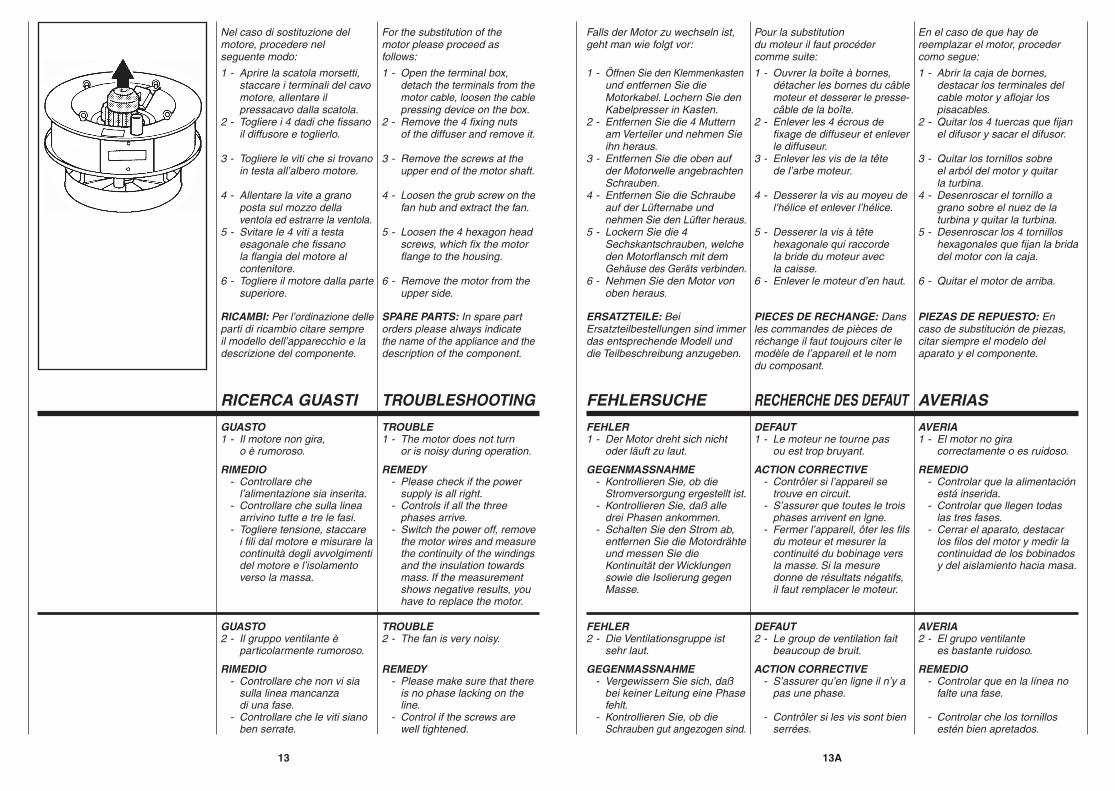
Nel caso di sostituzione delmotore, procedere nelseguente modo:
1 - Aprire la scatola morsetti, staccare i terminali del cavo motore, allentare il pressacavo dalla scatola.2 - Togliere i 4 dadi che fissano il diffusore e toglierlo.
3 - Togliere le viti che si trovano in testa all’albero motore.
4 - Allentare la vite a grano posta sul mozzo della ventola ed estrarre la ventola.5 - Svitare le 4 viti a testa esagonale che fissano la flangia del motore al contenitore.6 - Togliere il motore dalla parte superiore.
RICAMBI: Per l’ordinazione delleparti di ricambio citare sempreil modello dell’apparecchio e ladescrizione del componente.
For the substitution of themotor please proceed asfollows:
1 - Open the terminal box, detach the terminals from the motor cable, loosen the cable pressing device on the box.2 - Remove the 4 fixing nuts of the diffuser and remove it.
3 - Remove the screws at the upper end of the motor shaft.
4 - Loosen the grub screw on the fan hub and extract the fan.
5 - Loosen the 4 hexagon head screws, which fix the motor flange to the housing.
6 - Remove the motor from the upper side.
SPARE PARTS: In spare partorders please always indicatethe name of the appliance and thedescription of the component.
Falls der Motor zu wechseln ist,geht man wie folgt vor:
1 - Öffnen Sie den Klemmenkasten und entfernen Sie die Motorkabel. Lochern Sie den Kabelpresser in Kasten.2 - Entfernen Sie die 4 Muttern am Verteiler und nehmen Sie ihn heraus.3 - Entfernen Sie die oben auf der Motorwelle angebrachten Schrauben.4 - Entfernen Sie die Schraube auf der Lüfternabe und nehmen Sie den Lüfter heraus.5 - Lockern Sie die 4 Sechskantschrauben, welche den Motorflansch mit dem Gehäuse des Geräts verbinden.6 - Nehmen Sie den Motor von oben heraus.
ERSATZTEILE: BeiErsatzteilbestellungen sind immerdas entsprechende Modell unddie Teilbeschreibung anzugeben.
Pour la substitutiondu moteur il faut procédercomme suite:
1 - Ouvrer la boîte à bornes, détacher les bornes du câble moteur et desserer le presse- câble de la boîte.2 - Enlever les 4 écrous de fixage de diffuseur et enlever le diffuseur.3 - Enlever les vis de la tête de l’arbe moteur.
4 - Desserer la vis au moyeu de l’hélice et enlever l’hélice.
5 - Desserer la vis à tête hexagonale qui raccorde la bride du moteur avec la caisse.6 - Enlever le moteur d’en haut.
PIECES DE RECHANGE: Dansles commandes de pièces deréchange il faut toujours citer lemodèle de l’appareil et le nomdu composant.
En el caso de que hay dereemplazar el motor, procedercomo segue:
1 - Abrir la caja de bornes, destacar los terminales del cable motor y aflojar los pisacables.2 - Quitar los 4 tuercas que fijan el difusor y sacar el difusor.
3 - Quitar los tornillos sobre el arból del motor y quitar la turbina.4 - Desenroscar el tornillo a grano sobre el nuez de la turbina y quitar la turbina.5 - Desenroscar los 4 tornillos hexagonales que fijan la brida del motor con la caja.
6 - Quitar el motor de arriba.
PIEZAS DE REPUESTO: Encaso de substitución de piezas,citar siempre el modelo delaparato y el componente.
RICERCA GUASTI TROUBLESHOOTING RECHERCHE DES DEFAUTFEHLERSUCHE AVERIAS
