manual do usuáriousa - visitronicsusa.com · if the peripheral device is properly connected and...
TRANSCRIPT

User Manual
System Imagetronics
Version 5
Optical Medical Equipment

Índice
Main Cap. 1
Menus
Patients Cap. 2
Adicionar Editar Localizar Remover
Exam Cap. 3
Editar Visualizar Fotos Exportar Remover Novo Retinografia Colorida Red-free Angiografia Mesclar
Photos Cap. 4
Maximizar Editar Selecionar Remover Copiar/Colar Edição Editar Cronômetro
Photo Editing Cap. 5
Caixa de Ferramentas Contraste Brilho Saturação Gama Voltar Voltar Tudo Monocromático Arrastar/Ampliar Círculo Diâmetro Papilar Diâmetro Pap. de Referência Calibre Interno Calibre Externo Poligono Fechado Medida de Área Medida de Escavação Anotações Fonte Recorte
Appraisal Cap. 6
PDF Layout Selecionar Fotos Resolução Abrir Imprimir Remover Restaurar
Backup Cap. 7
Criar Volume Restaurar Volume & Exame Limpar HD
Configurações Cap. 8
Caminhos Médicos, Oper. e Convênios Clínica Máscara Câmera
11
12233
7 8 910101011
111112121212131313131313141414151515171717
3444556667
18 1919191920202021
21212223
232325262626

In the main software window Image Tronics are found three main menus: File, Settings and Help. These are shown in Figures 2, 3 and 4.
To open the software Image Tronics, just take two clicks with the left mouse button on the icon Visitronics, which is on the desktop of your computer. If the peripheral device is properly connected and connected to the PC, the window shown in Figure 1 opens.
Patients
Main
Menus
Clicking on the item Patient File menu (or type CTRL + P), the patient window is displayed to the user. This window, shown in Figure 5 (next page), contains two distinct parts. At the top of the window we find the patient data, tests, reports and PDFs, while on the bottom can be found an area where it shows thumbnails of the pictures of a selected test.
The top of the window is still divided by two tabs: "Patient" and "Print Layout". In the "Patient" tab, find the patient information, exam list he has already made, the test data that has been selected in the list and, finally, list of PDFs generated for this exam. Each of these topics will be discussed more thoroughly in the following sections.
Figure 1: Main Window
Figura2: Menu Arquivo
Figure 3: Menu Settings
Figura4: Menu Ajuda
1
Chapter 1
Chapter 2

Figure 5: Patient Window
Add
To add a patient, select the "Patient" tab, and click the button .... which is in the button bar at the top of this tab. The window shown in Figure 6 opens.
Fill in the required data (ID, patient and date of birth). The ID field can be alphanumeric (the chart code, ID, etc.) and must be unique for each patient. The Agreement and Phone fields are optional. After filling the data, click on "Add".
Figure 6: Window to add customers
Edition
After changing any of the patient for the fields, the button .... must be clicked for the changes to be saved.
2

Locate
Figure 7: Window to locate patients
Remove
To locate a previously registered patient, click the button .... . The window shown in Figure 7 will open. In this window we have two tabs: Nome e ID.
In Tab “Nome” there is a text field where you can enter the patient name you want to find. As you type, the list of names below will be updated displaying only patients that contain the text typed in any part of your name.
The tab "ID" behaves the same way: as enter the ID, the list is updated to show only those that contain the typed text.
After locating the desired patient, select it from the list and click "OK’’
To remove a patient, click the button ..... You will be warned that all the pictures of all the examinations of these patients are also excluded. Confirm by pressing "OK" for the two posts.
Exams The tests performed by a patient are organized by date, and presented to the user in a list displayed on the "Patient" tab, just above the "New Look" button. See example in Figure 8, the next page.
3
Chapter 3

When selecting an exam in this list, the data relating to him are loaded and the rest of the patient window is filled. Are these data: requesting physician's name, operator name, date of examination, observation and report, in addition to the list of PDFs already generated. At that moment the "View Photos" button has changed its text mode that displays the number of pictures that this examination, as well as the backup volume where to find these photos, if necessary. See example below in Figure 9.
Figure 8: List of examinations
Figure 9: Button View Photos
This button can also present another text: "missing photos". It appears when the photos are already deleted from the system (see procedure in the Backup section), to free up space on your hard disk.
Edition Whenever some information field "Selected Test" has been changed, the button .... must be clicked for the changes to take effect.
View Photos To see photos of a test, simply select the desired exam in the examination list and click the "View Photos" button. The thumbnails are loaded and displayed at the bottom of the window patients. See example 10 in Fig.
Export To export the photos to a test, select it in the examination list, click the right button and use the "Export Photos" option. See example 10 in Fig.
4

Figure 10: Thumbnails of the photos.
New
To perform a test, the patient must first be registered. With the patient located, click the button “Novo Exame”. If the camera is not found, a warning message is displayed. See example 11 in Fig.
If the camera is turned on and connected correctly, a new window will open. See example in Figure 12, next page ..
Figure 11: Warning message
The capture window is separated into two parts. The largest portion of it is occupied to display the last picture taken. The lower portion of this window is occupied by controls used during capture:
Salvar: Used the end of the examination to save the photos taken in the current patient.
Monocromático: Control used to switch the camera to monochrome, as well as the ISO.
Colorido: Used to change the camera to color mode, as well as to adjust the ISO.
ISO: rapid access control to the possible ISO settings that allow camera.
Cronômetro: Used in retinographer Stopwatch place during angiography.
Remove To remove an exam, use the menu shown in Figure 10 by clicking the "Delete" option. Confirm to be alerted that the photos will be lost.
5

Formatar Câmera: Maintains the initial setup time of the camera below. It should be used regularly, typically before starting an exam or at the end of it.
# Fotos: It shows how many pictures have been taken this exam.
Figure 12: Capture Window
Colors Retinography
Red-free
Angiography
To conduct an examination of fundus photography after opening a new survey, click the "Color" box. This control will put the digital camera in color mode, with pre-selected ISO. The ISO is also displayed on the screen and can be changed throughout the examination, if necessary.
For red-free photos, as well as position the green filter retinographer, click the "Monochrome" button. This control will put the digital camera in monochrome, with pre-selected for ISO monochrome. The ISO may be changed during the examination, if required.
To perform angiography, rather than activate the "Timer" the retinographer, use the "Timer" button on the system. This control, and set the camera in "Monochrome" and change the ISO, also starts an internal timer that will be linked to processed photos.
6

You can create a test starting at pictures of other tests. This examination is called "Mixed", identified in the examination list with a letter "M" after the date on which this test is created. To create a merged examination, select the first exam that will contribute photos and click "View Photos". For each photo should be included in the new survey, click on the thumbnail photo and click the "Merge" option from the menu that will open. A new window will open. This window has three buttons: “Esconder”, “Descartar” e “Criar”. In addition to these buttons, thumbnails of selected photos will also be displayed. Click on "Hide" and select the next photo in the currently exposed in the examination of the patient screen.
After adding all the pictures, click on the next exam that will contribute photos and repeat the above procedure. After you are finished adding photos of all required exams, click “Criar”. The new exam will be created. If you want to remove a picture added by mistake in the merge window, click the right mouse button on the thumbnail and click “Remover” the menu that will open.
If you want to give up to create the exam, click “Descartar” and all photos will be removed from the merge window.
The photos participating in a mixed examination show at the top, the date they were actually carried out.
MIX
When selecting an examination of the list of tests of the patient screen, the pictures are accessible via the button “Ver Fotos”.
The photo thumbnails are displayed at the bottom of the window patients. This region of the window can be resized to show thumbnails in full screen. To do this, click and drag the bar that separates the two parts (upper and lower) of the window, as in the example in Figure 13.
Photos
Figure 13: Bar dividing the patient window (left) and a window showing the maximum possible thumbnails.
7
Chapter 4

To maximize a picture (full screen), click with the right mouse button on the thumbnail and choose "Maximize" option. The menu with all the options is shown in Figure 14 below. The maximized photo will appear as in Figure 15. With maximized photo it is possible to give the "Zoom" by turning the middle mouse button. You can also change the picture by pressing the arrows right / left of the keyboard.
To end the photo viewing, press the ESC key on your keyboard.
Press the Ctrl key on your keyboard to start editing the photo.
Maximize
Figure 14: the photo thumbnail in the options menu.
Figure 15: Screen shot with a maximized picture. The image edges are the edges of the screen.
8

Edition
To start editing the photo, select the item "Edit" menu shown in Figure 14. If already maximized with the picture, press the Ctrl key on your keyboard. For editing, the window will look like the example shown in Figure 16.
The edit window displays at the top, the thumbnails of all the photos taken. With a click on the thumbnail, you can change the photo being edited. You can also browse through the thumbnails by clicking on the green arrows found at the bottom of the screen.
If the thumbnails are not displayed simultaneously, a scroll bar will appear below the arrows, as shown in the example in Figure 16.
On the left side of the screen we have the editing toolbox. This window is semi-transparent, so as not to impede the full view of the photo, and can be dragged anywhere, at any time. To do this, click and drag the window's title bar (top edge).
By clicking the right mouse button on the thumbnail, the menu displayed as an example in "Figure 17" will open.
Figure 17: thumbnail menu in the edit screen.
9
Figure 16

Select
To select a photo, simply click on the "Select" of the menus as in Figures 14 or 17. When you select a photo, it will be drawn with a red "X", as we can see in Figure 18.
Figure 18: Window of patients with 3:04 selected pictures (left).editing window with photos 4:05 selected (right)
After selecting photos you want to remove, click again with the right mouse button on any of the thumbnails (you can even click on a thumbnail that has not been selected), and click the "Remove all selected" option.
Remove
When you have finished editing a photo, all procedures used to improve the picture quality can be copied and applied to other photos in several different ways.
To copy editing done, click the right button on the thumbnail in the patient screen or edit, and click the "Copy editing" option. This option can be found as an example in Figure 14 (Patient screen) and Figure 17 (edit screen).
After copying the following ways necklace are available in the same menu (Figures 14 and 17):
Colar Edição: Will paste only on the picture, through which the menu was clicked.
Colar Edição nos Selecionados: Will put the issue on all pictures previously selected.
Colar Edição na Retinografia: Will put the issue on all pictures without timer. This will also include the red-free photos.
Colar Edição na Angiografia: Will put the issue on every shot with stopwatch.
Copy and Paste Editon
10

Edit Timer
Useful feature in situations where control “Iniciar Cronômetro” It has not been activated at the right time while capturing the photos.
To access this feature, click the right mouse button on the thumbnail of the photo you can estimate your timer value, and click on the option “Editar Cronômetro”, as in the example in Figure 14. The window as an example in Figure 19, is displayed to the user.
Enter the desired value to perform selected picture of the time and confirm. All other exam photos will be updated with this new reference.
Figure 19: Window for changing the timer.
The system allows two types of issues: treatment of images and drawings on the photo. With drawings can still perform linear measurements, area and excavation.
No editing done in the photo will change the original file and can be undone at any time, whenever the user wishes. All the user-edited commands are stored in the database and re-applied to the photo each time it is displayed on the screen or converted to PDF.
Photo Editing
Tool box
The Toolbox (see example in Figure 20) is where all the controls of treatment and design can be found.
At the top of the Toolbox have controls for image processing and at the bottom we have controls to make drawings, notes, linear measurements, area measurements, and excavation and cuttings.
The image processing controls are 'click-drag ". To use them, you must click on the position indicator (small arrow with green edges) and, keeping it clicked, drag the mouse to the right / left. While performing this operation, the system will give you a preview of the effect. When you release the mouse button, the position indicator back to its source (so you can apply more of this effect) and the effect is applied indeed. None of them has the minimum / maximum limitation, which can be used several times to obtain the desired effect.
All controls are explained in the sections to follow.
11
Chapter 5
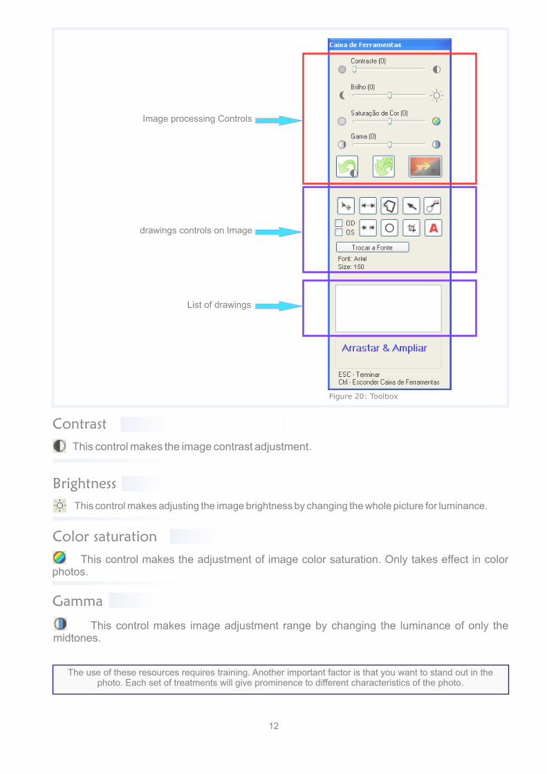
Image processing Controls
drawings controls on Image
Contrast
Figure 20: Toolbox
This control makes the image contrast adjustment.
Brightness
This control makes adjusting the image brightness by changing the whole picture for luminance.
Color saturation
This control makes the adjustment of image color saturation. Only takes effect in color photos.
Gamma
This control makes image adjustment range by changing the luminance of only the midtones.
The use of these resources requires training. Another important factor is that you want to stand out in the photo. Each set of treatments will give prominence to different characteristics of the photo.
List of drawings
12

Monochrome
Back All
Back
All image processing commands are organized as a "cell", being placed "on" the other. The "Back" button removes the last command given, keeping the others in this "cell".
Takes over the photo to its original state, emptying completely the "stack" of controls.
Works only on photos of fundus photography, this control turns the photo in monochrome. Pressing the control again, the picture returns to be colorful.
Drag and Zoom
With this selected control, the mouse will zoom functions and positioning. Zooming can be achieved in two different ways:
Turning the middle mouse button. Clicking and dragging the middle mouse button, selecting a rectangular area that the system attempts to expand. If the selected area is less than the maximum zoom, then the selected area will be ignored and the maximum zoom is applied.
Circle
This tool is used to create a circle on the photo. The construction method is simple: click on a photo point and holding down the mouse button, drag it to the desired circle. Can be used to define the unit of measure within the eye (diameter Papillary - DP), or simply to highlight a picture of the region.
Diameter Papillary
Figure 21: Set DP
13
To be able to perform linear and area within the eye, it is necessary first to define a "ruler", the measurement unit. This unit is the diameter of the papilla called only DP.
To set the DP, create a circle on the edge of the papilla, looking for the best average when the papilla is not uniform.
Select the newly created circle in the toolbox drawings list and, after selected, click the right mouse button on the list. Click on the item “Definir DP”, as shown in Figure 21.
Papillary diameter definition as described above has the operational scope only the picture where it was defined, namely only that photo will be possible to make linear and area measurements.

Reference diameter Papillary Papillary diameter reference is very similar to the papillary diameter, differing only in its scope of action. By setting the papillary diameter of reference, the user must inform you which eye it is: right or left.
After setting, as an example in Figure 22, all the pictures (of the same examination) that is identified as being the same eye (right / left) where the papillary diameter reference was defined, can now make linear and area measurements.
To identify the eye (right / left), you must use the control from the toolbox as in Figure 23. The purpose of this feature is the measure of peripheral areas of the eye, where you can not take them along with the papilla on the same photo.
Figure 22: Setting reference DPFigure 23: OD/OS
Internal caliber Tool used to perform linear measurements with arrows inside the measurement region.
The construction method for this measure is simple: click on the first point and keeping clicked, drag to the second point. When you release the mouse button, two new items will appear in the toolbox design list: the caliber and the text for the measurement performed.
The internal bore may be seen as an example in Figure 24.
Figure 24: Caliber Internal
Caliber Extern Tool used to perform linear measurements with arrows on the outside of the far region. The extent of this construction method is identical to the internal bore. The outer size can be seen as an example in Figure 25.
Figure 25: Caliber Extern
14

Polygon Closed
With this tool it is possible to create geometrical shapes closed in order to schedule a region or an area measure perform a measurement excavation.
The method of creating a closed polygon is simple: After selecting the tool, click with the left mouse button on the picture where you want the first vertex of the polygon. Position the mouse where you want the next vertex and give a new click with the left mouse button. It is not necessary to drag the mouse to the new position with the button, just reposition the mouse (with the left button of the mouse loose) and click to create a new vertex. To close the polygon, move the mouse to the position of the first vertex created and when a small circle appears, right-click New. If err the position of the vertex, you can not place it. Close the polygon, delete it, and then start again.
A polygon is displayed as an example in Figure 26.
Area Measurement To make a measurement area, use the Closed Polygon tool to determine the desired area, have defined Reference DP or DP. The measured area will only appear in the Toolbox just below the design list. Use the Text tool to write it on the photo. See the example in Figure 26.
Excavation Measure (cup/disk)
To perform this measurement, two polygons are needed: one on the perimeter of the optical disk (disk) and another about the perimeter of the glass (cup). After creating these polygons, select one in the drawings list and click the right mouse button, bringing up the menu. For each polígnos, select the option correspondete:“Definir Cup”/ “Definir Disk”.
Figures 27, 28 and 29 show an example.
15
Figure 26

Figura 27: Definindo Disk
Figura 28: Definindo Cup
16
Figure 27
Figure 28

Notes
This tool should be used whenever you want to enter text on the image. Its use is simple: select it in the toolbox, and then click the left mouse button on the location of the photo, where the text is inserted. A dialog box will prompt the text. Enter and click "OK".
Font
With this control you can change the font used to write on the photo. Depending on the size of the photo will be in PDF, the greater must be the source used.
You can also change the font of an already inserted text. To do this, select the text in the list of drawings and click the right mouse button. From the menu, select “Trocar Fonte”, as in the example in Figure 30.
Figure 30: Change text font already inserted.
SNIP
This feature should be used whenever you want to print the zoom a picture of the region.
When you select the tool, the picture is darkened all but one frame in the center of the screen. This table refers to the area to be cropped. In the lower right corner there is a small square drawn, click it with the left mouse button and drag to resize the area to be cropped. Click and drag any point within the area to reposition it. When finished selecting the desired area, click with the right mouse button anywhere in the photo point to complete the cut. Confirm when asked if you want to perform the clipping. The process is only completed at the end of photo editing. The picture 31 on the next page shows the feature.
17
Figure 29

Report
There are two ways to generate a report on the system.
The first is to fill the "Report" field in the patient window and use a vertical layout to generate the PDF. Horizontal layouts do not have room to report. Thus, the report will be printed along with the photos.
The second way to generate report is through an external editor and a standard file to report. The user creates a file to the standard adopted and, every time you click the "External Report" button on the screen patients, the system will check if there is already a report created for this exam. If so, it will be opened for editing. If there is no report to the folder configured, the system creates a copy of the standard report, rename the file to identify it as the selected exam and opens the external editor for the report is completed.
The system, at any time, store in a database external report or its existence. Only the report field is stored.
Figure 32 shows an example of the "Report" and the "external Report" button.
Figure 32: Report
The field “Laudo” it has the exact size that fits in the area for the report in PDF vertical. No lines and no more columns to be used.
Figura 31: Recorte
18
Chapter 6
Figure 31

Select Photos To select the photos that will make up the PDF, click the left mouse button on the thumbnail and holding the button, drag the thumbnail on the desired position in the layout. Release the button to which the thumbnail is displayed in the layout.
You can drag a photo from a layout to another, but in doing so, the process is restarted with the chosen photo in the new layout.
To remove a previously selected photo, click on its thumbnail with the right mouse button. Click "Clear Selection" button if you want to delete all photos in the layout.
Because it is a popular format, the file format "PDF" was chosen as the default output format for the pictures chosen to compose the report.
The system remains in the database all the information regarding the generated PDFs: photos used, layout, position of each photo in the layout, etc. With this, after the delivery of the document, the file can be safely deleted because the system allows its recreation at any time.
Can be generated as many PDFs are desired for an examination and there is no limit. They are organized by "pages", listed and identified by name.
The PDF generated name consists of the patient's name concatenated with the exam date and page number. See an example in Figure 33, next page.
Layout The system offers a wide range of layouts for the composition of the pictures that form the report. In the window patients have the "Print Layout" tab. Clicking on this tab, we see two other tabs: "Horizontal" and "Vertical". Within each of these tabs we see a collection of possible layouts. Altogether there are 5 horizontal layouts (with larger photos and unsupported to the report) and 8 vertical layouts (smaller photos, room to report shortly and clinical data more prominently).
19
Chapter 6

Open For a PDF is opened must have its description ended with a "+" sign in the list of PDFs as shown in Figure 33. If you have a "-" sign means that the file does not exist and needs to be restored before opening.
To open the existing file, double-click on the item in the PDF list.
The file can be opened also through its menu. Select the PDF in the list, click the right mouse button and click the "Open" option.
Here's an example of all menu options in Figure 34.
Figure 34
Print To print the PDF generated using the viewer's print command.
Remove The menu shown in Figure 34 presents two options to remove. The first, “Remover PDF” will delete the file and remove the database information for the PDF. The second “Remover (somente arquivo) PDF” delete the file but keeps the relevant information in the database.
List of PDFs
Figure 33: PDFs
Resolution selection
20
Resolution

The Imagetronic system automatically manages the necessity and creation of backup volumes.
Whenever the program starts, it makes the volume count of photos without backup, and when you reach the volume of a DVD, a message appears indicating that there are now photos in sufficient quantity to accomplish the creation of a more backup.
backup volumes are complementary, i.e., volume 2 does not eliminate the need to keep the volume 1. The contents of the packages are different and should all be stored. All volumes contain a copy of the updated database.
As show in Figure 3, use the "File" -> "Backup Control" menu. The window as in the example in Figure 35 will open.
Backup
Indicates what the next volume to be
created and allows you to change the
number.
current system status and amount of progress being
created.
Open Windows Explorer to the folder
with the created volumes.
Opens Nero software for recording media.
Create Volume To create a backup volume simply click the "Create Volume" button.
Figure 35: Backup
Restore When there is need to open a file that have already been removed, or update a PDF with images that have been edited, highlight the list PDF, open the menu and click the "Restore" option. The PDF will be recreated without a new page is generated.
21
Chapter 7

If you want the system has recorded the DVD, select the recording drive and place the media into the recorder.
Otherwise you must use third-party software (Nero, for example) to burn your DVD.
Independent recording later or let the system record following the process, the volume is first created in the temporary folder pointed to by the configuration. If you have problems during recording or wanted to record other DVDs with the same volume (for enhanced data security), the volume will be in HD until it is deleted by the user. Remember to label the DVD with the volume number engraved on it.
The button "Ver Fotos” It shows in his text which the volume where this examination, if required, as in Figure 36.
Restore Volume & Exam
There are two ways to restore data from a backup volume. The first is to restore the entire volume, typically only required the system restore after a computer crash. The second way is to restore only the test you want to open.
To restore an entire volume, they are given two options, as shown in Figure 35:
“Apenas Fotos”: It is the restoration of all the volume of photos but does not override the database.
“Fotos e Banco de Dados”: Restores all volume of photos and also change the database with the version in the backup.
When photos of an examination with backup have already been deleted from the computer, view photos button will indicate this, as shown in Figure 37.
Figure 36
Figure 37
In this situation, to open the pictures of the review, click the button to see photos and a message prompting you to restore this examination of Volume 1 will appear. See Figure 38.
Figure 38
Click in“Sim” and a standard Windows dialog box will open, asking you to find the file needed for the restoration of the review. This file will be shown how to locate the DVD or the folder where the backup is. Select the file and click Open.
The first time you open the photos after the restoration, the shipment will be very slow, because the system will be creating thumbnails again. Other times to click “Ver Fotos”, the thumbnails will open at the usual speed.
22

Figura 39
Select the options you would like to delete from your computer and click “Apagar”.
Remember to ensure that volumes are already on DVD.
Make copies of the reports before deleting them, as the system does not keep up these files.
To access the settings options, we use the "Settings" menu, as shown in Figure (39.The). Select one of the items on this menu and a window will open. In the following sections each of which is discussed.
Settings
Path In this configuration section of the paths used by the system can be configured. See example of the "Settings" window in Figure 40.
Export Directory Where the system will save the exported photos to an exam. Each patient will have a subfolder named after him.
Clean HD To keep your computer free of files that can be deleted in a secure and managed way, the system delivers “Limpar HD”. By clicking this button, a panel with few options will open. Example 39 below in Fig.
Temporary directory for further examination Where the system will keep the photos while the test is performed. When the "Save" button in the capture window is clicked, the photos are moved to the final exam directory.
Directory for creating PDF files Where the system will save the documents generated in PDF. There may be subfolders with the names of doctors or operators, if so configured.
23
Chapter 8
Figure(39.A)

Figura 40: Janela de Configurações
Where the system will create the backup volumes (even before recording on DVD). For each volume created a subfolder is created.
Directory photosWhere the system will save the photos of exams. Each patient will have a subfolder whose name is an internal code.
Report Genereric File that the system will copy and rename for each patient that you want to create an external report.
Report Edition Executable that the system will call for the user to write his report.
Directory for creating reports Where the system will save the reports. There may be subfolders with the names of doctors or operators, if so configured.
Software PDF reader Executable that the system will call to scan and display the PDF document. Adobe Acrobat Reader will set by default.
Temporary directory to backup
24
Figura 40

For better organization of the generated documents (especially in the case of many users), it can allow the system to generate documents in subfolders with the name of the requesting physician or operator.
Number of thumbnails columns
Organize PDFs and Reports in subfolders
Doctors, Operators and Covenants In this option you can add doctors, operators and agreements for quick access. See the configuration window example in Figure 41.
Add to them is very simple: Enter the text and press "Enter" on the keyboard or the "Add" button. Do this for the window tabs and finish by clicking "Ok".
Figure 41: tabs Doctors configuration window, Operators and Covenants
25
For best viewing of thumbnails in the patient screen, you can change the amount that will be in each "Shoreline" thumbnails. This setting should be changed according to the monitor and the resolution used. For example:
to 1440X900: Use 5 columns (Minimum configuration)to 1920X1080: Use 7 columns

Clinic Through the window shown in Figure 42 you can set up the clinical data that will be used in printouts generated by the system.
Fields that must be filled are: “Nome da Clínica”, “Endereço da Clínica” e “Telefone da Clínica”. Although the names of the fields indicate the content that should be filled, any text can be used. For example, with the telephone can be placed email or clinical site.
The clinic's logo used by the system must have size 300x150 pixels. Any image with different size that can be used but will suffer the appropriate resizing to fill that space. In this process the picture may be distorted. When the image is not size compatible with expectations, an exclamation mark will blink next to the image.
To choose the image, click the "..." button. Files with extension "jpg" or "bmp" are accepted as logo.
Figure 42: Configuration dialog of the clinical data.
Mask The mask setting is made in the installation and should not be changed by the user.
Câmera The camera setup window is divided into two parts (ISO and Rotate / Flip). See Figure 43. The ISO setting is used by the system to change the digital camera every time the "Color" control and "Monochrome" are triggered in the capture window (Figure 12, page 6).
The standard is ISO 100 and ISO 400 for color photos to monochrome photos. If needed, change these settings to more appropriate values.
Rotation / Reversal should not be changed by the user.
Figure 43
26