manual for models: scb37-110 scb107-110 scb107e-110 scb37-110.pdf · i manual for models: scb37-110...
TRANSCRIPT
I
MANUAL FOR MODELS:
SCB37-110
SCB107-110 SCB107E-110
11 METERS CASSEGRAIN EARTH STATION ANTENNAS
I
C o n t e n t 1 General………………………………………………………………………………...2 2 Technical Specifications………………………………………………………………3 2.1 Specifications of the model SCB37-110…………………………………………….3 2.2 Specifications of the model SCB107-110…………………………………………...4 2.3 Specifications of the model SCB107E-110………………………………………….5
3 Structural Character and Operational Principle………………………………………..6 3.1 System Structural Character...................................................................…..................6 3.1.1 Antenna Structural Character..………………………………………….……….7 3.1.2 Antenna Pedestal Structure…..…………………………………………………12 3.1.3 Feed Structure…..………………………………………………………………15
3.2 Antenna Operation Principle..................................................................................... 17
4 Maintenance..............................................................................................................….17
4.1 Operation and Maintenance of Antenna.............…............ .....................…............. 17 4.2 Operation and Maintenance of Servo Equipment......................................…............ 20
2
1 General
The 11m antenna, a synthetic Cassegrain dual-reflector antenna models SCB37-110,
SCB107-110 and SCB107E-110, adopts some new technologies, such as high-performance
corrugated horn and broadband microwave network, etc.
The antenna performance meets the requirements of ITU-R/ITU-T、INTELSAT IESS-207 and
Resolution 572 of Anatel standards. It is not only provided with many excellent electric
performances, such as high efficiency, low sidelobe, low cross polarization, low Voltage
standing waves ratio (VSWR), high G/T value, but also with excellent characters including
appropriate structural design, strong wind resistance ability, beautiful appearance and high
tracking accuracy. It is a new generation satellite communication antenna.
This manual is applicable for the follow models of antenna:
SCB37-110: C-Band Cassegrain 11 meters antenna for Circular or Linear Polarization;
SCB107-110: Ku-Band Cassegrain 11 meters antenna for Linear Polarization;
SCB107E-110: Extend Ku-Band Cassegrain 11 meters antenna for Linear Polarization;
3
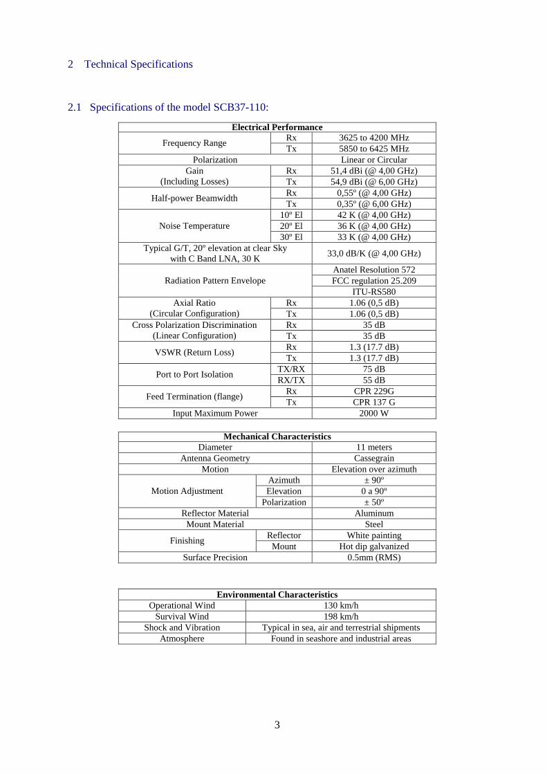
2 Technical Specifications
2.1 Specifications of the model SCB37-110:
Electrical Performance Rx 3625 to 4200 MHz
Frequency Range Tx 5850 to 6425 MHz
Polarization Linear or Circular Rx 51,4 dBi (@ 4,00 GHz) Gain
(Including Losses) Tx 54,9 dBi (@ 6,00 GHz) Rx 0,55º (@ 4,00 GHz)
Half-power Beamwidth Tx 0,35º (@ 6,00 GHz)
10º El 42 K (@ 4,00 GHz) 20º El 36 K (@ 4,00 GHz) Noise Temperature 30º El 33 K (@ 4,00 GHz)
Typical G/T, 20º elevation at clear Sky with C Band LNA, 30 K
33,0 dB/K (@ 4,00 GHz)
Anatel Resolution 572 FCC regulation 25.209 Radiation Pattern Envelope
ITU-RS580 Rx 1.06 (0,5 dB) Axial Ratio
(Circular Configuration) Tx 1.06 (0,5 dB) Rx 35 dB Cross Polarization Discrimination
(Linear Configuration) Tx 35 dB Rx 1.3 (17.7 dB)
VSWR (Return Loss) Tx 1.3 (17.7 dB)
TX/RX 75 dB Port to Port Isolation
RX/TX 55 dB Rx CPR 229G
Feed Termination (flange) Tx CPR 137 G
Input Maximum Power 2000 W
Mechanical Characteristics Diameter 11 meters
Antenna Geometry Cassegrain Motion Elevation over azimuth
Azimuth ± 90º Elevation 0 a 90º Motion Adjustment
Polarization ± 50º Reflector Material Aluminum Mount Material Steel
Reflector White painting Finishing
Mount Hot dip galvanized Surface Precision 0.5mm (RMS)
Environmental Characteristics Operational Wind 130 km/h
Survival Wind 198 km/h Shock and Vibration Typical in sea, air and terrestrial shipments
Atmosphere Found in seashore and industrial areas
4
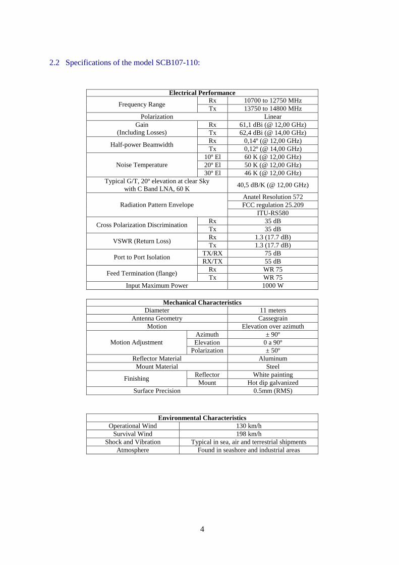
2.2 Specifications of the model SCB107-110:
Electrical Performance Rx 10700 to 12750 MHz
Frequency Range Tx 13750 to 14800 MHz
Polarization Linear Rx 61,1 dBi (@ 12,00 GHz) Gain
(Including Losses) Tx 62,4 dBi (@ 14,00 GHz) Rx 0,14º (@ 12,00 GHz)
Half-power Beamwidth Tx 0,12º (@ 14,00 GHz)
10º El 60 K (@ 12,00 GHz) 20º El 50 K (@ 12,00 GHz) Noise Temperature 30º El 46 K (@ 12,00 GHz)
Typical G/T, 20º elevation at clear Sky with C Band LNA, 60 K
40,5 dB/K (@ 12,00 GHz)
Anatel Resolution 572 FCC regulation 25.209 Radiation Pattern Envelope
ITU-RS580 Rx 35 dB
Cross Polarization Discrimination Tx 35 dB Rx 1.3 (17.7 dB)
VSWR (Return Loss) Tx 1.3 (17.7 dB)
TX/RX 75 dB Port to Port Isolation
RX/TX 55 dB Rx WR 75
Feed Termination (flange) Tx WR 75
Input Maximum Power 1000 W
Mechanical Characteristics Diameter 11 meters
Antenna Geometry Cassegrain Motion Elevation over azimuth
Azimuth ± 90º Elevation 0 a 90º Motion Adjustment
Polarization ± 50º Reflector Material Aluminum Mount Material Steel
Reflector White painting Finishing
Mount Hot dip galvanized Surface Precision 0.5mm (RMS)
Environmental Characteristics Operational Wind 130 km/h
Survival Wind 198 km/h Shock and Vibration Typical in sea, air and terrestrial shipments
Atmosphere Found in seashore and industrial areas
5
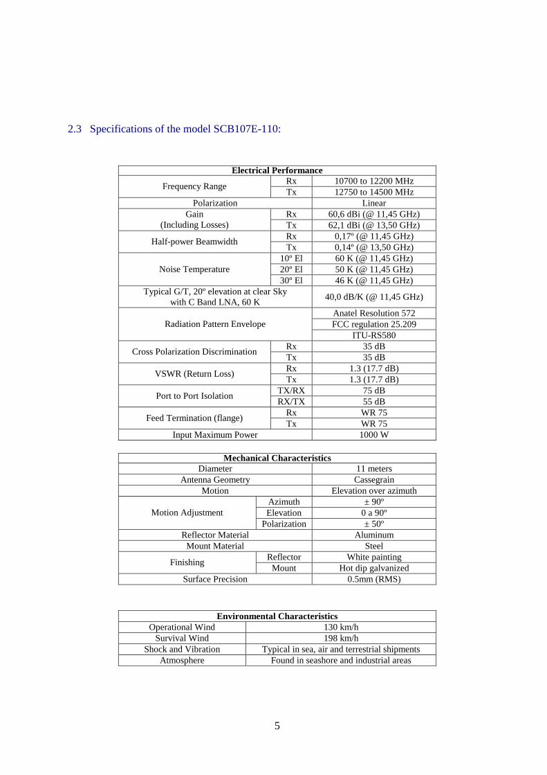
2.3 Specifications of the model SCB107E-110:
Electrical Performance Rx 10700 to 12200 MHz
Frequency Range Tx 12750 to 14500 MHz
Polarization Linear Rx 60,6 dBi (@ 11,45 GHz) Gain
(Including Losses) Tx 62,1 dBi (@ 13,50 GHz) Rx 0,17º (@ 11,45 GHz)
Half-power Beamwidth Tx 0,14º (@ 13,50 GHz)
10º El 60 K (@ 11,45 GHz) 20º El 50 K (@ 11,45 GHz) Noise Temperature 30º El 46 K (@ 11,45 GHz)
Typical G/T, 20º elevation at clear Sky with C Band LNA, 60 K
40,0 dB/K (@ 11,45 GHz)
Anatel Resolution 572 FCC regulation 25.209 Radiation Pattern Envelope
ITU-RS580 Rx 35 dB
Cross Polarization Discrimination Tx 35 dB Rx 1.3 (17.7 dB)
VSWR (Return Loss) Tx 1.3 (17.7 dB)
TX/RX 75 dB Port to Port Isolation
RX/TX 55 dB Rx WR 75
Feed Termination (flange) Tx WR 75
Input Maximum Power 1000 W
Mechanical Characteristics Diameter 11 meters
Antenna Geometry Cassegrain Motion Elevation over azimuth
Azimuth ± 90º Elevation 0 a 90º Motion Adjustment
Polarization ± 50º Reflector Material Aluminum Mount Material Steel
Reflector White painting Finishing
Mount Hot dip galvanized Surface Precision 0.5mm (RMS)
Environmental Characteristics Operational Wind 130 km/h
Survival Wind 198 km/h Shock and Vibration Typical in sea, air and terrestrial shipments
Atmosphere Found in seashore and industrial areas
6
3 Structural Character and Operational Principle
3.1 System Structural Character
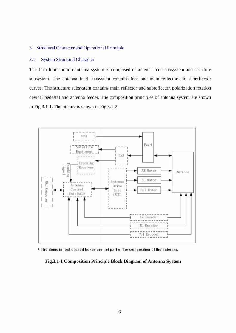
The 11m limit-motion antenna system is composed of antenna feed subsystem and structure
subsystem. The antenna feed subsystem contains feed and main reflector and subreflector
curves. The structure subsystem contains main reflector and subreflector, polarization rotation
device, pedestal and antenna feeder. The composition principles of antenna system are shown
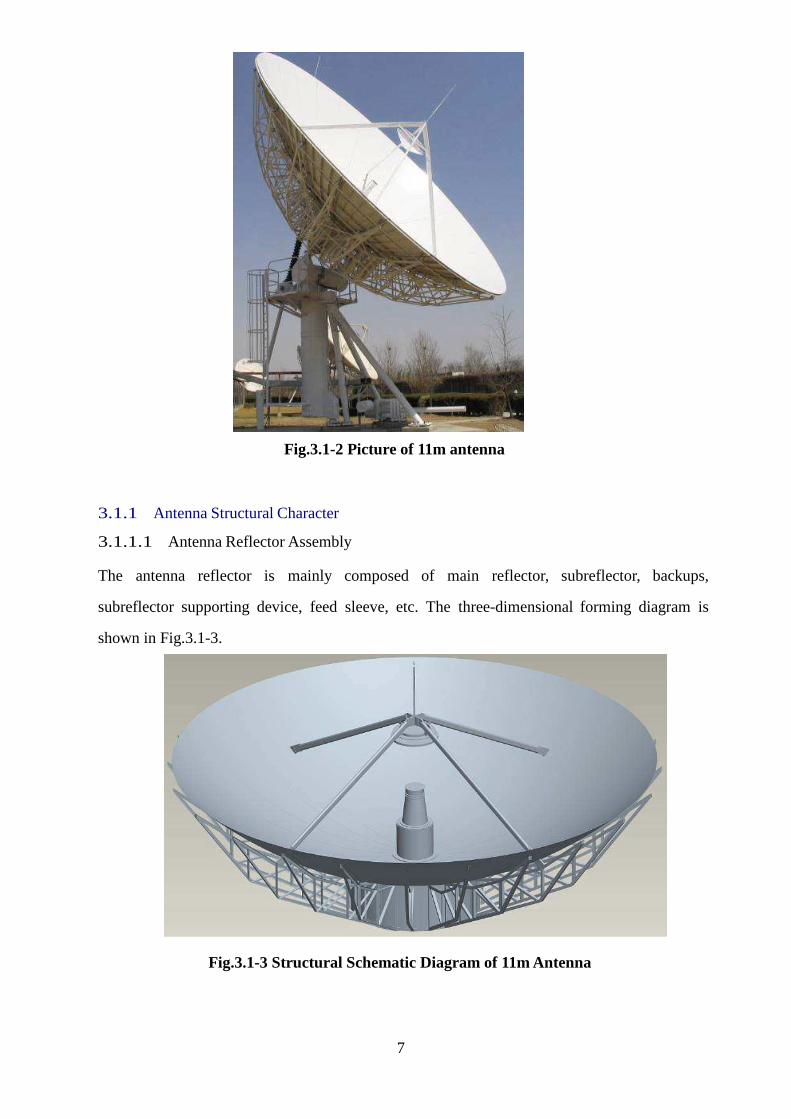
in Fig.3.1-1. The picture is shown in Fig.3.1-2.
Fig.3.1-1 Composition Principle Block Diagram of Antenna System
7
Fig.3.1-2 Picture of 11m antenna 3.1.1 Antenna Structural Character
3.1.1.1 Antenna Reflector Assembly The antenna reflector is mainly composed of main reflector, subreflector, backups,
subreflector supporting device, feed sleeve, etc. The three-dimensional forming diagram is
shown in Fig.3.1-3.
Fig.3.1-3 Structural Schematic Diagram of 11m Antenna
8
3.1.1.2 Main Reflector Design The main reflector is one of the core components of the antenna system. Its theoretical curved
surface is formed by synthetic curve rotating around the axis of the antenna. The antenna
reflector is divided into multiple plates because of cumulative materials, manufacturing
engineering, final assembly adjustment, etc. The reflector is divided into two rings. Inner ring
reflector is divided into 20 same sector unit plates and the outer ring is divided into 20 sector
unit plates. So the main reflector of antenna is composed of 40 reflector units.
The stretched and shaped 2A12-O aluminum board with thickness of δ=2mm is used as
individual sector plate after quenching, stretching and shaping. Z type aluminum casting
material is used as back rib after quenching, stretching and shaping in order to perform
positioning with rivet the die table for riveting rib and reflector. Each sector plate is supported
at backups via 6 stretching bolts. In order to ensure the process precision, such process
technology as first bonding and second riveting is adopted to improve the strength of
individual plate and reduce the number of rivets and thus decrease the local deformation of
plate caused by riveting points. The high precision mould and tool set up process are used for
all procedures, such as stretching, stretch bending, riveting. The accuracy of the individual
plate is ≤0.25mm (R.M.S). The reassembly precision of whole main reflector is ≤0.45mm
(R.M.S).
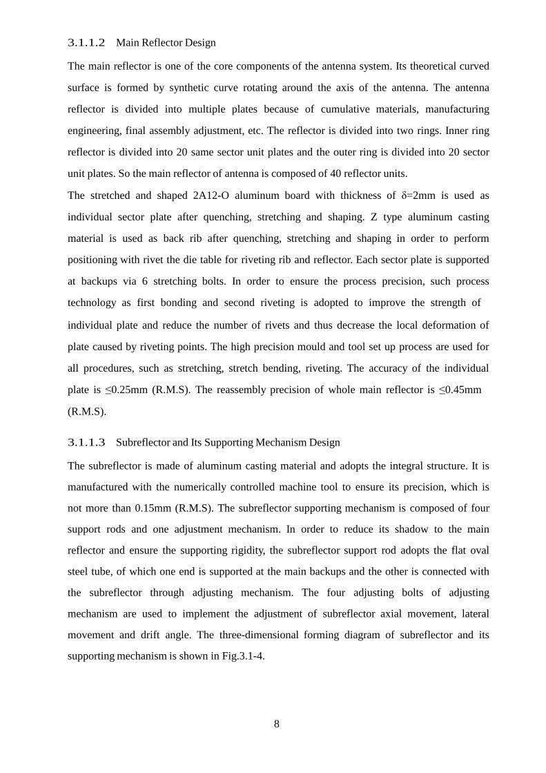
3.1.1.3 Subreflector and Its Supporting Mechanism Design
The subreflector is made of aluminum casting material and adopts the integral structure. It is
manufactured with the numerically controlled machine tool to ensure its precision, which is
not more than 0.15mm (R.M.S). The subreflector supporting mechanism is composed of four
support rods and one adjustment mechanism. In order to reduce its shadow to the main
reflector and ensure the supporting rigidity, the subreflector support rod adopts the flat oval
steel tube, of which one end is supported at the main backups and the other is connected with
the subreflector through adjusting mechanism. The four adjusting bolts of adjusting
mechanism are used to implement the adjustment of subreflector axial movement, lateral
movement and drift angle. The three-dimensional forming diagram of subreflector and its
supporting mechanism is shown in Fig.3.1-4.
9
Fig.3.1-4 Three-dimensional Diagram of Subreflector and Supporting Mechanism
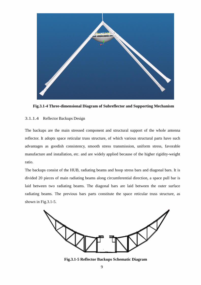
3.1.1.4 Reflector Backups Design
The backups are the main stressed component and structural support of the whole antenna
reflector. It adopts space reticular truss structure, of which various structural parts have such
advantages as goodish consistency, smooth stress transmission, uniform stress, favorable
manufacture and installation, etc. and are widely applied because of the higher rigidity-weight
ratio.
The backups consist of the HUB, radiating beams and hoop stress bars and diagonal bars. It is
divided 20 pieces of main radiating beams along circumferential direction, a space pull bar is
laid between two radiating beams. The diagonal bars are laid between the outer surface
radiating beams. The previous bars parts constitute the space reticular truss structure, as
shown in Fig.3.1-5.
Fig.3.1-5 Reflector Backups Schematic Diagram
10
The HUB is the basic stressed component in the antenna structure and also the connection
component between the antenna reflector and antenna pedestal. All loads of antenna reflector
are down-transferred concentratively through the HUB. So the HUB must have higher
rigidity.
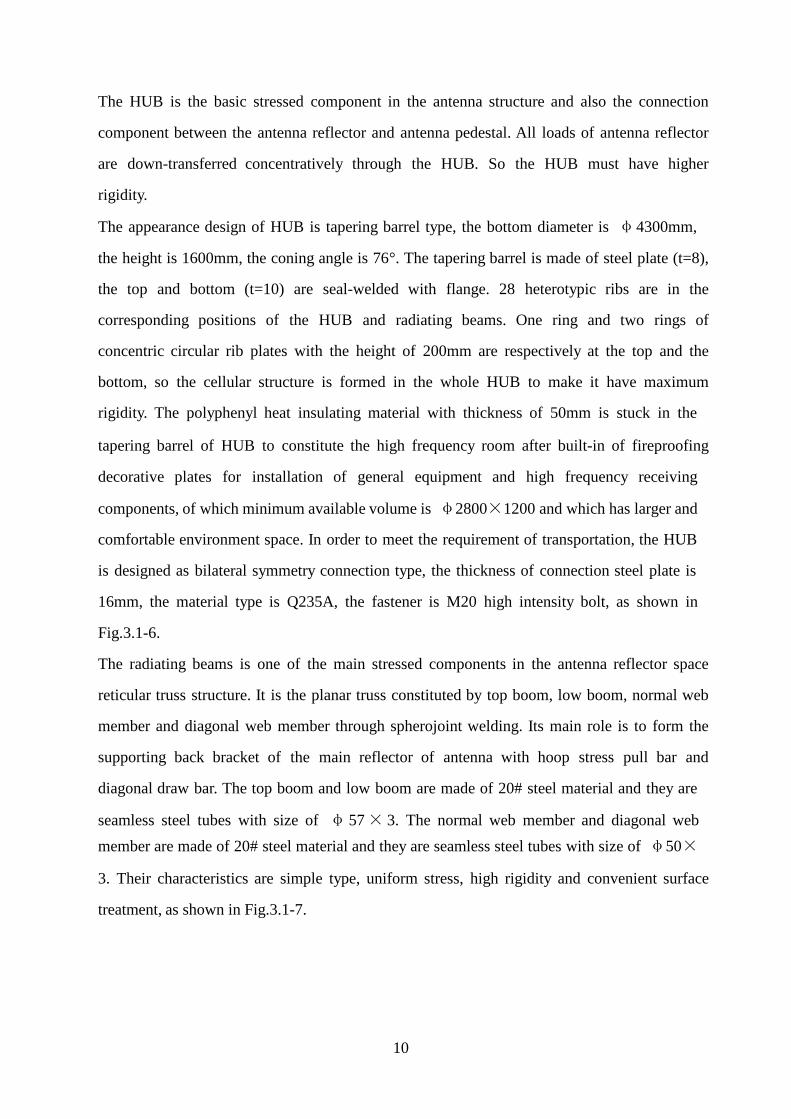
The appearance design of HUB is tapering barrel type, the bottom diameter is φ4300mm, the height is 1600mm, the coning angle is 76°. The tapering barrel is made of steel plate (t=8),
the top and bottom (t=10) are seal-welded with flange. 28 heterotypic ribs are in the
corresponding positions of the HUB and radiating beams. One ring and two rings of
concentric circular rib plates with the height of 200mm are respectively at the top and the
bottom, so the cellular structure is formed in the whole HUB to make it have maximum
rigidity. The polyphenyl heat insulating material with thickness of 50mm is stuck in the
tapering barrel of HUB to constitute the high frequency room after built-in of fireproofing
decorative plates for installation of general equipment and high frequency receiving
components, of which minimum available volume is φ2800×1200 and which has larger and comfortable environment space. In order to meet the requirement of transportation, the HUB
is designed as bilateral symmetry connection type, the thickness of connection steel plate is
16mm, the material type is Q235A, the fastener is M20 high intensity bolt, as shown in
Fig.3.1-6.
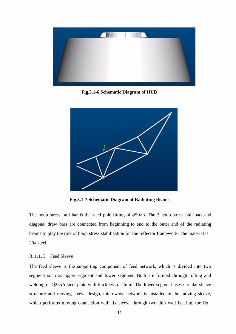
The radiating beams is one of the main stressed components in the antenna reflector space
reticular truss structure. It is the planar truss constituted by top boom, low boom, normal web
member and diagonal web member through spherojoint welding. Its main role is to form the
supporting back bracket of the main reflector of antenna with hoop stress pull bar and
diagonal draw bar. The top boom and low boom are made of 20# steel material and they are
seamless steel tubes with size of φ 57 × 3. The normal web member and diagonal web
member are made of 20# steel material and they are seamless steel tubes with size of φ50×
3. Their characteristics are simple type, uniform stress, high rigidity and convenient surface
treatment, as shown in Fig.3.1-7.
11
Fig.3.1-6 Schematic Diagram of HUB
Fig.3.1-7 Schematic Diagram of Radiating Beams
The hoop stress pull bar is the steel pole fitting of φ50×3. The 3 hoop stress pull bars and
diagonal draw bars are connected from beginning to end to the outer end of the radiating
beams to play the role of hoop stress stabilization for the reflector framework. The material is
20# steel.
3.1.1.5 Feed Sleeve
The feed sleeve is the supporting component of feed network, which is divided into two
segment such as upper segment and lower segment. Both are formed through rolling and
welding of Q235A steel plate with thickness of 4mm. The lower segment uses circular sleeve
structure and moving sleeve design, microwave network is installed in the moving sleeve,
which performs moving connection with fix sleeve through two thin wall bearing, the fix
12
sleeve is fixed in the HUB. The upper segment uses tapering sleeve structure, of which the
upper end surface performs positioning connection with corrugated horn and the lower end
surface performs positioning with the rabbet of moving sleeve and the flanges are connected
with bolts. So, the linear polarization direction of feed network can be adjusted only by
rotating moving sleeve for implementing linear polarization surface adjustment which uses
electric mode.
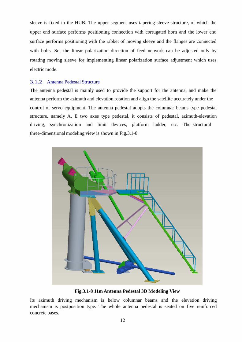
3.1.2 Antenna Pedestal Structure
The antenna pedestal is mainly used to provide the support for the antenna, and make the
antenna perform the azimuth and elevation rotation and align the satellite accurately under the
control of servo equipment. The antenna pedestal adopts the columnar beams type pedestal
structure, namely A, E two axes type pedestal, it consists of pedestal, azimuth-elevation
driving, synchronization and limit devices, platform ladder, etc. The structural
three-dimensional modeling view is shown in Fig.3.1-8.
Fig.3.1-8 11m Antenna Pedestal 3D Modeling View
Its azimuth driving mechanism is below columnar beams and the elevation driving mechanism is postposition type. The whole antenna pedestal is seated on five reinforced concrete bases.
13
3.1.2.1 Azimuth Part
The azimuth part consists of the azimuth-elevation supporting combination, tripod, azimuth
lower bearing pedestal combination, azimuth upper bearing pedestal combination, etc.
The azimuth-elevation supporting combination is a T-type combination constituted by the
kingpost with Ф900mm and tripod. The kingpost with length of 3.45m is decumbent on the
previous one. The tripod is constituted with three inclined struts that their upper ends are
converged at one point. The lower ends of the three inclined struts are fixed at the base with
bolts, and the upper ends are connected to the azimuth upper bearing pedestal combination
and fixed at the intersection point of their center connecting lines to form the upper axle head
for azimuth rotation. The lower bearing pedestal combination is fixed at the base with bolts,
the centers of the upper and lower bearing are at the same plumb line and form the azimuth
axis.
The annular contact thrust spherical-roller bearing 9069332 is installed in azimuth lower
bearing pedestal, the knuckle sliding bearing is installed in azimuth upper bearing pedestal.
The upper and lower axle heads are respectively installed into the upper and lower rotation
axle pedestal holes. In this way, the azimuth-elevation bearing combination can perform
azimuth movement under the role of the azimuth driving device, the azimuth travel range is
within ±90º.
3.1.2.2 Elevation Part
The elevation part mainly consists of the azimuth-elevation bearing combination, driving
pedestal E, elevation bearing pedestal combination, etc.
On the support arms at the two sides of decumbent cylinder at the top of azimuth-elevation
bearing combination, there is a pair of axle holes orthogonal with the azimuth axis, in which
are the bearings. The two axle holes connect the elevation bearing pedestal combination with
the decumbent cylinder via the clevis pin with head to form the elevation axis E. In this way,
the antenna can perform the elevation movement under the role of elevation driving device.
The elevation rotation range is within 0º~90º.
14
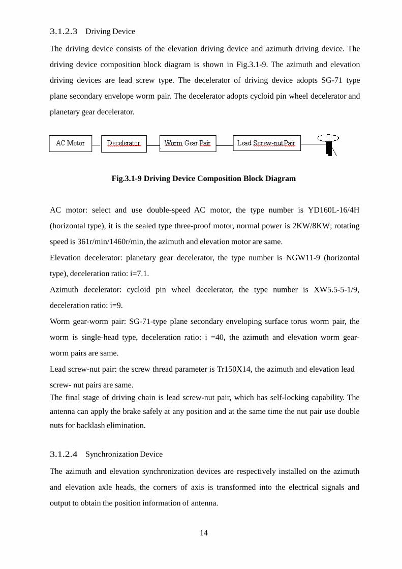
3.1.2.3 Driving Device The driving device consists of the elevation driving device and azimuth driving device. The
driving device composition block diagram is shown in Fig.3.1-9. The azimuth and elevation
driving devices are lead screw type. The decelerator of driving device adopts SG-71 type
plane secondary envelope worm pair. The decelerator adopts cycloid pin wheel decelerator and
planetary gear decelerator.
Fig.3.1-9 Driving Device Composition Block Diagram AC motor: select and use double-speed AC motor, the type number is YD160L-16/4H
(horizontal type), it is the sealed type three-proof motor, normal power is 2KW/8KW; rotating
speed is 361r/min/1460r/min, the azimuth and elevation motor are same.
Elevation decelerator: planetary gear decelerator, the type number is NGW11-9 (horizontal
type), deceleration ratio: i=7.1.
Azimuth decelerator: cycloid pin wheel decelerator, the type number is XW5.5-5-1/9,
deceleration ratio: i=9.
Worm gear-worm pair: SG-71-type plane secondary enveloping surface torus worm pair, the
worm is single-head type, deceleration ratio: i =40, the azimuth and elevation worm gear-
worm pairs are same.
Lead screw-nut pair: the screw thread parameter is Tr150X14, the azimuth and elevation lead screw- nut pairs are same.
The final stage of driving chain is lead screw-nut pair, which has self-locking capability. The
antenna can apply the brake safely at any position and at the same time the nut pair use double
nuts for backlash elimination.
3.1.2.4 Synchronization Device
The azimuth and elevation synchronization devices are respectively installed on the azimuth
and elevation axle heads, the corners of axis is transformed into the electrical signals and
output to obtain the position information of antenna.
15
3.1.2.5 Limit Device
In order to make the antenna rotate within the safe range, install safe limit protection device
on the azimuth and elevation axle heads of antenna to make the antenna operate safely.
The limit device consists of the limit switch and mass. The limit swicths are respectivily
installed on the two extreme positions of travel range of azimuth and elevation axes, when the
antenna travels the extrem position and the mass touches switch, the power supply is switched
off.
3.1.2.6 Platform and Ladder
For the convenience of maintenance and ensuring safeguard, the guardrail, ladder and
platform are installed on the antenna pedestal.
3.1.3 Feed Structure
The feed is the core of the whole antenna and its performances directly affect the RF
performance of the antenna. So the optimized scheme and design should be performed more
carefully. The feed is composed of corrugated horn and microwave network.
3.1.3.1 Corrugated Horn
Rx and Tx singles of the antenna share the same corrugated horn. It’s required to realize
ideal radiation at the Rx and Tx bands, with rotary symmetry and low cross polarization
radiation pattern and low VSWA characteristic.
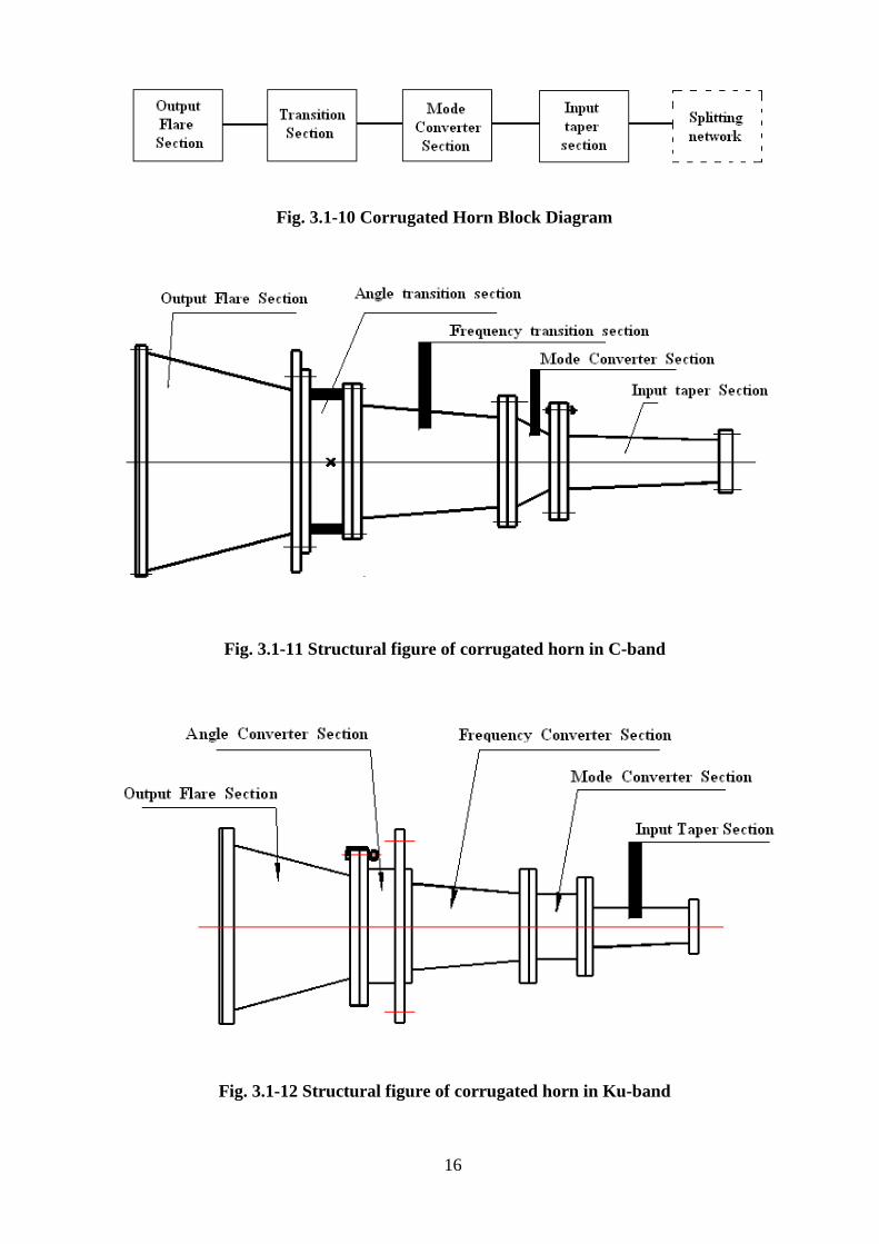
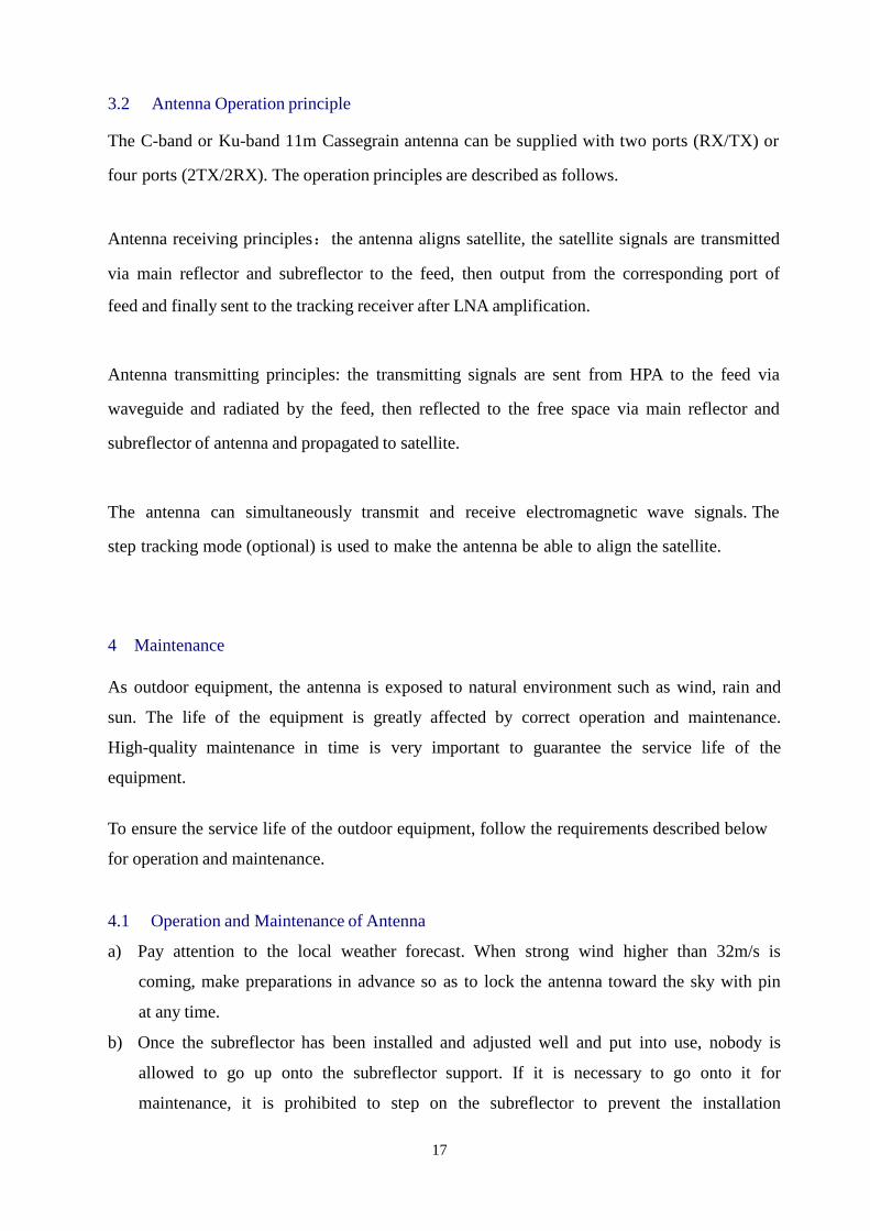
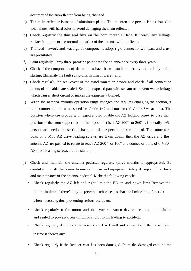
The corrugated horn consists of input taper section, mode converter section, transition
section and output flare section. The transition section may include frequency transition
section and angle transition section. If the frequency band is narrow, there is no frequency
section. The principle block diagram is shown in Fig.3.1-10. The purpose of the mode
converter section is to well convert the main mode TE11 in the circular waveguide into the
main HE11 in the corrugated waveguide, at the same time, maintain good match and reject the
generation of the harmful high order mode EH12. The transition section is to accomplish the
transition of frequency and the angle between the mode converter section and the output flare
section, at the same time, reject the generation of the harmful high order mode EH12. The
output flare section is to generate the required subreflector brim illumination level. The mode
converter section is the key design. The ring-loaded slots in the mode converter section are
adopted to expand the frequency band. The structural figure of the whole horn in C-band and
Ku-band is shown in Fig. 3.1-11 and Fig. 3.1-12, respectively.
16
Fig. 3.1-10 Corrugated Horn Block Diagram
Fig. 3.1-11 Structural figure of corrugated horn in C-band
Fig. 3.1-12 Structural figure of corrugated horn in Ku-band
17
3.2 Antenna Operation principle
The C-band or Ku-band 11m Cassegrain antenna can be supplied with two ports (RX/TX) or
four ports (2TX/2RX). The operation principles are described as follows.
Antenna receiving principles:the antenna aligns satellite, the satellite signals are transmitted
via main reflector and subreflector to the feed, then output from the corresponding port of
feed and finally sent to the tracking receiver after LNA amplification.
Antenna transmitting principles: the transmitting signals are sent from HPA to the feed via
waveguide and radiated by the feed, then reflected to the free space via main reflector and
subreflector of antenna and propagated to satellite.
The antenna can simultaneously transmit and receive electromagnetic wave signals. The
step tracking mode (optional) is used to make the antenna be able to align the satellite.
4 Maintenance As outdoor equipment, the antenna is exposed to natural environment such as wind, rain and
sun. The life of the equipment is greatly affected by correct operation and maintenance.
High-quality maintenance in time is very important to guarantee the service life of the
equipment.
To ensure the service life of the outdoor equipment, follow the requirements described below
for operation and maintenance.
4.1 Operation and Maintenance of Antenna
a) Pay attention to the local weather forecast. When strong wind higher than 32m/s is
coming, make preparations in advance so as to lock the antenna toward the sky with pin
at any time.
b) Once the subreflector has been installed and adjusted well and put into use, nobody is
allowed to go up onto the subreflector support. If it is necessary to go onto it for
maintenance, it is prohibited to step on the subreflector to prevent the installation
18
accuracy of the subreflector from being changed.
c) The main reflector is made of aluminum plates. The maintenance person isn’t allowed to
wear shoes with hard soles to avoid damaging the main reflector.
d) Check regularly the thin seal film on the horn mouth surface. If there’s any leakage,
replace it in time or the normal operation of the antenna will be affected.
e) The feed network and wave-guide components adopt rigid connections. Impact and crush
are prohibited.
f) Paint regularly. Spray three-proofing paint onto the antenna once every three years.
g) Check if the components of the antenna have been installed correctly and reliably before
startup. Eliminate the fault symptoms in time if there’s any.
h) Check regularly the seal cover of the synchronization device and check if all connection
points of all cables are sealed. Seal the exposed part with sealant to prevent water leakage
which causes short circuit or makes the equipment burned.
i) When the antenna azimuth operation range changes and requires changing the section, it
is recommended the wind speed be Grade 1~2 and not exceed Grade 3~4 at most. The
position where the section is changed should enable the AZ leading screw to pass the
position of the front support rod of the tripod, that is at AZ 100°or 260°. Generally 4~5
persons are needed for section changing and one person takes command. The connector
bolts of 6 M30 AZ drive leading screws are taken down, then the AZ drive and the
antenna AZ are pushed to rotate to reach AZ 260°or 100° and connector bolts of 6 M30
AZ drive leading screws are reinstalled. j) Check and maintain the antenna pedestal regularly (three months is appropriate). Be
careful to cut off the power to ensure human and equipment Safety during routine check
and maintenance of the antenna pedestal. Make the following checks:
• Check regularly the AZ left and right limit the EL up and down limit.Remove the
failure in time if there’s any to prevent such cases as that the limit cannot function
when necessary, thus preventing serious accidents.
• Check regularly if the motor and the synchronization device are in good condition
and sealed to prevent open circuit or short circuit leading to accident.
• Check regularly if the exposed screws are fixed well and screw down the loose ones
in time if there’s any.
• Check regularly if the lacquer coat has been damaged. Paint the damaged coat in time
19
(with zinc chromate primer and white polyurethane enamel.
• Check frequently all structural parts and rotating parts (shaft, bearing, leading
screw, worm gear reducer, planetary reducer and cycloid pinwheel reducer). Resolve
the problem in time if there’s any.
k) Overhaul of Antenna Pedestal ( the equipment should be stopped, once every three years)
• Check if all parts and components are damaged. Replace the damaged one in time if
there’s any.
• Clean, derust and oil all moving parts to guarantee flexible movement.
• Clean and adjust the axis, bearing, leading screw, worm gear reducer, planetary
reducer and cycloid pinwheel reducer. Replace the damaged or nearly damaged
component in time and apply enough lubricant (the lubricant grease is MnS2 EP lithium
grease, the oil is high-grade heavy-duty gear oil) at the same time to ensure flexible
movement. The lubricant grease and oil should be filled as described in (q). The grease
and oil must be filled sufficiently, missing and inadequacy will cause serious results and
the moving parts will be damaged in short time.
• Painting: spray paint in an all-round way once every three years. Clean the original
lacquer coat before painting, then paint it with zinc chromate primer as required
(once to twice) and white polyurethane enamel (twice to three times as required).
l) There’re two levels of moving speed of the antenna: fast and slow. The fast level is used
for antenna section changing, stowing and satellite searching and the slow level for
tracking satellite in normal operation.
m) In case of natural disasters such as windstorm and earthquake, check the equipment
constantly and replace the damaged parts and components in time.
n) When the wind speed has reached the speed to stow the antenna, if extremely strong wind
above Grade 10 is forecast (consider the wind speed at that time according to the
forecast), rotate the antenna 2 hours in advance to the stowing position facing the sky.
o) The leading screw cover is used to protect the leading screw. If damaged, repair or
replace it immediately.
p) Check the shaft, bearing, leading screw, worm gear reducer, planetary reducer and cycloid
pinwheel reducer once every three months and apply lubricant (the grease is MnS2 EP
lithium grease, the oil is high-grade heavy-duty gear oil) at the same time to ensure
flexible movement. The method is:
• Apply lubricant grease to the AZ and EL reducer box. Take down the organic
20
glass plate from the box, then fill up with mushy lubricant mixed by MnS2 EP lithium
grease and high-grade engine oil.
• Smear the AZ and EL leading screw with MnS2 EP lithium grease. The method is:
open the leading screw protection cover and smear the leading screw thread surface
with grease uniformly.
• Fill the oil cups of the AZ and EL rotating axles with MnS2 EP lithium grease (or
mixed with high-grade engine oil to be mushy grease) using pressing oil gun to lubricate
the rotating axles.
• Lubricate the planetary reducer and the cycloid pinwheel reducer. The method is
to fill the grease hole with heavy-duty gear oil.
4.2 Operation and Maintenance of Servo Equipment
a) Don’t turn on and turn off the power switches frequently to prevent the components
inside the cabinet from being damaged.
b) Hot-plug is prohibited to prevent the equipment or peripheral components from being
damaged and prevent malfunction.
c) Be careful to set parameters in system menu. Don’t modify the parameters rashly.
Don’t modify the system parameters, check them regularly. Once they are found to
have been changed, restore them to the original value in time.
d) Hot-plug may damage the equipment.