manual for rp114 netgear router
TRANSCRIPT

Reference Guide for theModel RP114 Web SafeRouter
SM-RP114NA-2July 2001
NETGEAR, Inc.4500 Great America ParkwaySanta Clara, CA 95054 USAPhone 1-888-NETGEAR

e in aled andre is nonce tod to try
ation
© 2001 by NETGEAR, Inc. All rights reserved.
Trademarks
NETGEAR and FirstGear are trademarks Netgear, Inc.
Microsoft, Windows, and Windows NT are registered trademarks of Microsoft Corporation.
Other brand and product names are registered trademarks or trademarks of their respective holders.
Statement of Conditions
In the interest of improving internal design, operational function, and/or reliability, NETGEAR reserves the right tomake changes to the products described in this document without notice.
NETGEAR does not assume any liability that may occur due to the use or application of the product(s) or circuitlayout(s) described herein.
Federal Communications Commission (FCC) Compliance Notice: Radio Frequency Notice
This equipment has been tested and found to comply with the limits for a Class B digital device, pursuant topart 15 of the FCC Rules. These limits are designed to provide reasonable protection against harmful interferencresidential installation. This equipment generates, uses, and can radiate radio frequency energy and, if not instalused in accordance with the instructions, may cause harmful interference to radio communications. However, theguarantee that interference will not occur in a particular installation. If this equipment does cause harmful interfereradio or television reception, which can be determined by turning the equipment off and on, the user is encourageto correct the interference by one or more of the following measures:
• Reorient or relocate the receiving antenna.
• Increase the separation between the equipment and receiver.
• Connect the equipment into an outlet on a circuit different from that to which the receiver is connected.
• Consult the dealer or an experienced radio/TV technician for help.
EN 55 022 Declaration of Conformance
This is to certify that the Model RP114 Web Safe Router is shielded against the generation of radio interference inaccordance with the application of Council Directive 89/336/EEC, Article 4a. Conformity is declared by the applicof EN 55 022 Class B (CISPR 22).
ii

Vfgr) kann
Markt
ons set
e notes
t
rea
Bestätigung des Herstellers/Importeurs
Es wird hiermit bestätigt, daß das Model RP114 Web Safe Router gemäß der im BMPT-AmtsblVfg 243/1991 und46/1992 aufgeführten Bestimmungen entstört ist. Das vorschriftsmäßige Betreiben einiger Geräte (z.B. Testsendejedoch gewissen Beschränkungen unterliegen. Lesen Sie dazu bitte die Anmerkungen in der Betriebsanleitung.
Das Bundesamt für Zulassungen in der Telekommunikation wurde davon unterrichtet, daß dieses Gerät auf dengebracht wurde und es ist berechtigt, die Serie auf die Erfüllung der Vorschriften hin zu überprüfen.
Certificate of the Manufacturer/Importer
It is hereby certified that the Model RP114 Web Safe Router has been suppressed in accordance with the conditiout in the BMPT-AmtsblVfg 243/1991 and Vfg 46/1992. The operation of some equipment (for example, testtransmitters) in accordance with the regulations may, however, be subject to certain restrictions. Please refer to thin the operating instructions.
Federal Office for Telecommunications Approvals has been notified of the placing of this equipment on the markeand has been granted the right to test the series for compliance with the regulations.
Voluntary Control Council for Interference (VCCI) Statement
This equipment is in the second category (information equipment to be used in a residential area or an adjacent athereto) and conforms to the standards set by the Voluntary Control Council for Interference by Data ProcessingEquipment and Electronic Office Machines aimed at preventing radio interference in such residential areas.
When used near a radio or TV receiver, it may become the cause of radio interference.
Read instructions for correct handling.
Customer Support
Refer to the Support Information Card that shipped with your Model RP114 Web Safe Router.
World Wide Web
NETGEAR maintains a World Wide Web home page that you can access at the universal resource locator (URL)http://www.netgear.com. A direct connection to the Internet and a Web browser such as Internet Exploreror Netscape are required.
iii

iv

Contents
About This Guide
Technical Support ............................................................................................................ xv
Related Publications ........................................................................................................ xv
Typographical Conventions ............................................................................................xvii
Special Message Formats ..............................................................................................xvii
Chapter 1Introduction
About the Router ............................................................................................................1-1
Key Features ..................................................................................................................1-1
Content Filtering .......................................................................................................1-3
Security ....................................................................................................................1-3
Autosensing 10/100 Ethernet ...................................................................................1-4
TCP/IP ......................................................................................................................1-4
Easy Installation and Management ..........................................................................1-5
Maintenance and Support ........................................................................................1-5
Chapter 2Setting Up the Hardware
Package Contents ..........................................................................................................2-1
Local Network Hardware Requirements .........................................................................2-2
PC Requirements ..............................................................................................2-2
Access Device Requirement .............................................................................2-2
The Router’s Front Panel ...............................................................................................2-3
The Router’s Rear Panel ................................................................................................2-4
Connecting the Router ....................................................................................................2-4
Connecting to your Local Ethernet Network .............................................................2-4
Connecting to Your Internet Access Device .............................................................2-5
Connecting the Power Adapter ................................................................................2-5
Verifying Power ........................................................................................................2-6
Contents v

Chapter 3Preparing Your Network
Preparing Your Personal Computers for IP Networking .................................................3-1
Configuring Windows 95 or later for IP Networking ........................................................3-2
Configuring TCP/IP Properties .................................................................................3-4
Verifying TCP/IP Properties (Windows) ...................................................................3-4
Configuring the Macintosh for IP Networking .................................................................3-5
Verifying TCP/IP Properties (Macintosh) ..................................................................3-6
Your Internet Account .....................................................................................................3-7
Login Protocols ........................................................................................................3-7
Account Information .................................................................................................3-8
Obtaining ISP Configuration Information (Windows) .........................................3-8
Obtaining ISP Configuration Information (Macintosh) .......................................3-9
Ready for Configuration ................................................................................................3-10
Chapter 4Basic Configuration of the Router
Configuring for Internet Access ......................................................................................4-1
Configuring for Content Filtering .....................................................................................4-7
E-Mail .......................................................................................................................4-8
Keyword ...................................................................................................................4-9
Schedule ................................................................................................................4-10
Trusted ................................................................................................................... 4-11
Logs .......................................................................................................................4-12
Chapter 5Advanced Configuration of the Router
System Settings ..............................................................................................................5-1
System Tab ..............................................................................................................5-1
Dynamic DNS ...........................................................................................................5-2
Password .................................................................................................................5-2
LAN Setup ......................................................................................................................5-3
DHCP .......................................................................................................................5-3
LAN TCP/IP ..............................................................................................................5-4
Configuring for Port Forwarding to Local Servers ..........................................................5-6
Local Web and FTP Server Example .................................................................5-7
Local Game Host or Videoconference Example ................................................5-8
vi Contents

Static Routes ..................................................................................................................5-8
Static Route Example .............................................................................................5-10
Chapter 6Maintenance
System Status ................................................................................................................6-1
DHCP Table ....................................................................................................................6-4
Software Upgrade ...........................................................................................................6-4
Configuration File Management .....................................................................................6-5
Restore and Backup the Configuration ....................................................................6-5
Erase the Configuration ...........................................................................................6-5
Chapter 7Using the Manager Interface for Initial Router Configuration
Connecting for Configuration ..........................................................................................7-1
Using the Manager Interface ..........................................................................................7-3
Login ........................................................................................................................7-3
Navigating the Manager ...........................................................................................7-4
Manager Menu Summary .........................................................................................7-4
General Setup Menu ................................................................................................7-6
WAN Setup ..............................................................................................................7-7
LAN Setup ................................................................................................................7-8
LAN Port Filter Setup Menu ...............................................................................7-8
TCP/IP and DHCP Setup ..................................................................................7-9
Manager Password Setup ...................................................................................... 7-11
Chapter 8Using the Manager Interface to Configure the Router for Internet Access
Internet Access Configuration ........................................................................................8-1
Remote Node Setup Menu .......................................................................................8-3
Editing IP Options ...........................................................................................................8-6
Editing Filter Sets ...........................................................................................................8-8
Configuration for Local Servers ....................................................................................8-10
Local Web and FTP Server Example ............................................................... 8-11
Local Game Host or Videoconference Example ..............................................8-12
Setting Static Routes ....................................................................................................8-12
Static Route Example .............................................................................................8-15
Dynamic DNS ...............................................................................................................8-17
Contents vii

Chapter 9Using the Manager Interface for Advanced System Maintenance
System Status ................................................................................................................9-1
Log and Trace .................................................................................................................9-4
View Error Log .........................................................................................................9-4
Syslog ......................................................................................................................9-5
Diagnostic Menu .............................................................................................................9-6
Back Up and Restore Configuration ...............................................................................9-8
Backing Up and Restoring the Configuration Using FTP .........................................9-8
Software Update .............................................................................................................9-9
Updating Router Software Using FTP ......................................................................9-9
Command Interpreter Mode ...........................................................................................9-9
Remote Management ...................................................................................................9-10
Chapter 10Configuring Filters
Router Filter Structure ..................................................................................................10-1
Configuring a Filter Set .................................................................................................10-2
Configuring a Filter Rule ...............................................................................................10-6
TCP/IP Filter Rule ..................................................................................................10-6
Generic Filter Rule .................................................................................................10-9
Applying a Filter Set ...................................................................................................10-10
Default Filters ............................................................................................................. 10-11
Filter 1: NetBIOS_WAN ........................................................................................ 10-11
Filter 2: NetBIOS_LAN ......................................................................................... 10-11
Filter 3: TEL_FTP_WEB_WAN ............................................................................. 10-11
Chapter 11Troubleshooting
Basic Functioning ......................................................................................................... 11-1
PWR LED Not On .................................................................................................. 11-1
Test LED Never Blinks or LED Stays On ............................................................... 11-2
LNK/ACT LEDs Not On .......................................................................................... 11-2
Troubleshooting the Web Configuration Interface ........................................................ 11-2
Troubleshooting the ISP Connection ............................................................................ 11-3
Troubleshooting a TCP/IP Network Using a Ping Utility ............................................... 11-5
Testing the LAN Path to Your Router ..................................................................... 11-5
viii Contents
Testing the Path from Your PC to a Remote Device .............................................. 11-7
Troubleshooting the Manager Interface ........................................................................ 11-7
Restoring the Default Configuration and Password ...................................................... 11-8
Using the Default Reset button .............................................................................. 11-8
Appendix ATechnical Specifications
General Specifications ................................................................................................... A-1
Appendix BNetwork and Routing Basics
Basic Router Concepts .................................................................................................. B-1
What is a Router? ................................................................................................... B-1
Routing Information Protocol ................................................................................... B-2
IP Addresses and the Internet ................................................................................. B-2
Netmask .................................................................................................................. B-4
Subnet Addressing .................................................................................................. B-5
Private IP Addresses ............................................................................................... B-7
Single IP Address Operation Using NAT ................................................................. B-8
MAC Addresses and Address Resolution Protocol ................................................. B-9
Domain Name Server .............................................................................................. B-9
IP Configuration by DHCP .................................................................................... B-10
Ethernet Cabling .......................................................................................................... B-10
Uplink Switches, Crossover Cables, and MDI/MDIX Switching .............................B-11
Cable Quality ..........................................................................................................B-11
Glossary
Index
Contents ix

x Contents

Figure 2-1. RP114 Front Panel ...................................................................................2-3
Figure 2-2. RP114 Rear Panel ...................................................................................2-4
Figure 4-1. Login window ...........................................................................................4-2
Figure 4-2. Browser-based configuration main menu ................................................4-2
Figure 4-3. Browser-based Setup Wizard, first screen ...............................................4-3
Figure 4-4. Browser-based Setup Wizard, second screen .........................................4-4
Figure 4-5. Browser-based Setup Wizard, third screen .............................................4-6
Figure 5-1. LAN Setup Menu ......................................................................................5-3
Figure 5-2. Port Forwarding Menu .............................................................................5-6
Figure 5-3. Static Route Summary Table ...................................................................5-8
Figure 5-4. Static Route Entry and Edit Menu ............................................................5-9
Figure 5-5. Static Route Example ............................................................................ 5-11
Figure 6-1. System Status screen ..............................................................................6-1
Figure 6-2. Router Statistics screen ...........................................................................6-3
Figure 6-3. DHCP Table .............................................................................................6-4
Figure 7-1. Manager Main Menu ................................................................................7-3
Figure 7-2. Menu 1 - General Setup ...........................................................................7-6
Figure 7-3. Menu 2 - WAN Setup ...............................................................................7-7
Figure 7-4. Menu 3 - LAN Setup ................................................................................7-8
Figure 7-5. Menu 23 - System Password ................................................................. 7-11
Figure 8-1. Menu 4 - Internet Access Setup ...............................................................8-2
Figure 8-2. Menu 11.1 - Remote Node Profile ............................................................8-4
Figure 8-3. Menu 11.3 - Remote Node Network Layer Options .................................8-6
Figure 8-4. Menu 21 - Filter Set Configuration ...........................................................8-8
Figure 8-5. Menu 11.5 - Remote Node Filters ............................................................8-9
Figure 8-6. Menu 15 - SUA Server Setup ................................................................ 8-11
Figure 8-7. IP Static Routing Table Example ............................................................8-13
Figure 8-8. Menu 12.1 - Edit IP Static Route ............................................................8-14
Figure 8-9. Static Route Example ............................................................................8-16
Figure 8-10. Menu 1.1 - Configure Dynamic DNS ......................................................8-17
Figure 9-1. Menu 24 - System Maintenance ..............................................................9-2
Figure 9-2. Menu 24.1 - System Maintenance - Status ..............................................9-2
Figure 9-3. Menu 24.4 - System Maintenance - Diagnostic .......................................9-7
Figure 10-1. Menu 21 - Filter Set Configuration .........................................................10-2
Figure 10-2. Menu 21.1 - Filter Rules Summary ........................................................10-3
xi

Figure 10-3. Menu 21.1.1 - TCP/IP Filter Rule ...........................................................10-5
Figure B-1. Three Main Address Classes .................................................................. B-3
Figure B-2. Example of Subnetting a Class B Address ............................................. B-5
Figure B-3. Single IP Address Operation Using NAT ................................................ B-8
xii

Table 2-1. LED Descriptions .....................................................................................2-3
Table 4-1. Log entry descriptions ............................................................................4-12
Table 4-2. Log display buttons ................................................................................4-13
Table 5-1. Dynamic DNS configuration fields ...........................................................5-2
Table 5-2. DHCP Setup Fields .................................................................................5-4
Table 5-3. LAN TCP/IP Setup Fields .......................................................................5-4
Table 5-4. Port Table Entries (Example) ...................................................................5-7
Table 5-5. Edit IP Static Route Fields ......................................................................5-9
Table 6-1. Menu 3.2 - System Status Fields .............................................................6-2
Table 6-2. Router Statistics Fields ...........................................................................6-3
Table 7-1. Manager Menu Commands ....................................................................7-4
Table 7-2. Manager Menu Summary .......................................................................7-4
Table 7-3. WAN Setup Fields ...................................................................................7-7
Table 7-4. Menu 3.1 - LAN Port Filter Setup Fields ..................................................7-9
Table 7-5. Menu 3.2 - TCP/IP and DHCP Setup Fields .........................................7-10
Table 8-1. Remote Node Profile Fields ....................................................................8-4
Table 8-2. Remote Node Network Layer Options Fields ..........................................8-7
Table 8-3. Remote Node Filters Fields .....................................................................8-9
Table 8-4. Menu 15 Field Entries (Example) ........................................................... 8-11
Table 8-5. Edit IP Static Route Fields ....................................................................8-14
Table 8-6. Dynamic DNS Configuration Fields ......................................................8-17
Table 9-1. System Maintenance Status ....................................................................9-3
Table 9-2. System Maintenance Status Fields .........................................................9-3
Table 9-3. System Maintenance - Log and Trace Fields ..........................................9-4
Table 9-4. System Maintenance - UNIX Syslog Fields .............................................9-5
Table 9-5. System Maintenance - Diagnostic Fields .................................................9-7
Table 10-1. Abbreviations Used in Menu 21.1 - Filter Rules Summary ...................10-3
Table 10-2. Abbreviations Used if Filter Type Is IP ...................................................10-4
Table 10-3. Abbreviations Used if Filter Type Is GEN ...............................................10-4
Table 10-4. TCP/IP Filter Rule Fields ......................................................................10-7
Table 10-5. Generic Filter Rule Fields .....................................................................10-9
Table B-1. Netmask Notation Translation Table for One Octet ................................ B-6
Table B-2. Netmask Formats .................................................................................... B-6
Table B-3. UTP Ethernet cable wiring, straight-through ......................................... B-10
xiii

xiv

m) that
s on
s
gernet.t. The
e
is
About This Guide
Congratulations on your purchase of the NETGEAR™ Model RP114 Web Safe Router.
The Model RP114 router provides connection for multiple personal computers (PCs) to theInternet through an external broadband access device (such as a cable modem or DSL modeis normally intended for use by a single PC.
Technical Support
For help with any technical issues, contact Customer Support at 1-888-NETGEAR, or visit uthe Web at www.NETGEAR.com. The NETGEAR Web site includes an extensive knowledgebase, answers to frequently asked questions, and a means for submitting technical questiononline.
Related Publications
As you read this document, you may be directed to various RFC documents for furtherinformation. An RFC is a Request For Comment (RFC) published by the Internet EngineerinTask Force (IETF), an open organization that defines the architecture and operation of the IntThe RFC documents outline and define the standard protocols and procedures for the Internedocuments are listed on the World Wide Web atwww.ietf.organd are mirrored and indexed atmany other sites worldwide.
For more information about address assignment, refer to the IETF documents RFC 1597,AddressAllocation for Private Internets,and RFC 1466,Guidelines for Management of IP Address Spac.
Note: If you are unfamiliar with networking and routing, refer toAppendix B, “Networkand Routing Basics,” to become more familiar with the terms and procedures used in thmanual.
About This Guide xv

Reference Guide for the Model RP114 Web Safe Router
For more information about IP address translation, refer to RFC 1631,The IP Network AddressTranslator (NAT).
xvi About This Guide

Reference Guide for the Model RP114 Web Safe Router
r
Typographical Conventions
This guide uses the following typographical conventions:
italics Book titles and UNIX file, command, and directory names.
courier font Screen text, user-typed command-line entries.
Initial Caps Menu titles and window and button names.
[Enter] Named keys in text are shown enclosed in square brackets. The notation[Enter] is used for the Enter key and the Return key.
[Ctrl]+C Two or more keys that must be pressed simultaneously are shown in textlinked with a plus (+) sign.
ALL CAPS DOS file and directory names.
Special Message Formats
This guide uses the following formats to highlight special messages:
Note: This format is used to highlight information of importance or special interest.
Caution: This format is used to highlight information that will help you preventequipment failure or loss of data.
Warning: This format is used to highlight information about the possibility of injury oequipment damage.
Danger: This format is used to alert you that there is the potential for incurring anelectrical shock if you mishandle the equipment.
About This Guide xvii


) toodem.
ing
ywords,
L)
Chapter 1Introduction
This chapter describes the features of the NETGEAR Model RP114 Web Safe Router anddiscusses planning considerations for installation. The software version described is v3.26.
About the Router
The Model RP114 Web Safe Router with 4-port switch connects your local area network (LANthe Internet through an external single-user access device such as a cable modem or DSL m
The Model RP114 router provides you with multiple Web content filtering options, plus browsactivity reporting and instant alerts -- both via e-mail. Parents and network administrators canestablish restricted access policies based on time-of-day, Website addresses and address keand share high-speed cable/DSL Internet access for up to 253 personal computers. NetworkAddress Translation (NAT) protects you from hackers.
With minimum setup, you can install and use the router within minutes.
Key Features
The Model RP114 router provides the following features:
• Security
– Parental control of web browsing and newsgroup access using Web Address (URkeyword blocking
– Auditing and e-mail reporting of web browsing activities
– Blocking can be scheduled by day and time
– Network Address Translation (NAT) hides local PCs from the Internet
Introduction 1-1

Reference Guide for the Model RP114 Web Safe Router
ons
L
– Powerful packet filtering capabilities
– Incoming port forwarding and DMZ for specific services
• Built in 4-port 10/100 Mbps Switch
– Allows LAN connections at 10 megabits per second (Mbps) or 100 Mbps
– Autosensing for Ethernet (10BASE-T) or Fast Ethernet (100BASE-Tx) transmissi
– Auto UplinkTM (autosensing MDI/MDIX) configures each port for normal or uplinkconnection
– Half-duplex or full-duplex operation
• Ethernet connection to a wide area network (WAN) device, such as a cable modem or DSmodem
– RJ-45 interface allowing connection to a 10BASE-T device
• Protocol Support
– IP routing
– Dynamic extended Network Address Translation (NAT+) with port forwarding foroperation with a single static or dynamic IP address
– Dynamic Host Configuration Protocol (DHCP) server for dynamically assigningnetwork configuration information to PCs on the LAN
– DHCP client for dynamically obtaining configuration information from the InternetService Provider (ISP)
– DNS Proxy for simplified configuration
– PPP over Ethernet (PPPoE) support
• Login capability
Automatically executes user login for
– RoadRunner cable modem service,
– PPP over Ethernet accounts, PPTP login (for European service providers)
– BigPond service (for Telstra Australia)
• Easy installation and management
– Easy, web-based setup for configuration of most features
– Built-in Manager interface for configuration of advanced features, accessible byTelnet Protocol
1-2 Introduction

Reference Guide for the Model RP114 Web Safe Router
m
ords
g to
ed,.
eber
wedw data
• Front panel LEDs for easy monitoring of status and activity
• Flash memory for firmware upgrade
• Five-year warranty, two years on power adapter
• Free technical support seven days a week, twenty-four hours a day
Content Filtering
With its content filtering features, the Model RP114 router prevents objectionable content froreaching your PCs. Its content filtering features include:
• Content filtering by domain or keywordThe Model RP114 router uses content filtering to enforce your network’s Internet accesspolicies. The router allows you to control access to Internet content by screening for keywwithin Web URLs or newsgroup names.
• Logging of inappropriate useYou can configure the Model RP114 router to log access to Web sites and to e-mail the loyou. You can also configure the router to send an immediate alert e-mail message to youwhenever a local user attempts to access a blocked Web site.
Security
The Model RP114 router is equipped with several features designed to maintain security, asdescribed in this section.
• PCs Hidden by NATNetwork address translation (NAT) opens a temporary path to the Internet for requestsoriginating from the local network. Requests originating from outside the LAN are discardpreventing users outside the LAN from finding and directly accessing the PCs on the LAN
• Port Forwarding with NATAlthough NAT prevents Internet locations from directly accessing the PCs on the LAN, throuter allows you to direct incoming traffic to specific PCs based on the service port numof the incoming request, or to one designated “DMZ” host computer. You can specifyforwarding of single ports or ranges of ports.
• Packet FilteringThe Model RP114 router provides extensive packet filtering capabilities. Packets are alloor discarded based on their source or destination addresses, service port numbers, or rapatterns within the packet.
Introduction 1-3

Reference Guide for the Model RP114 Web Safe Router
ps
itch,
/IP)
onlyviceo
P
gng then
from
ys-on
Autosensing 10/100 Ethernet
With its internal, 4-port 10/100 switch, the Model RP114 router can connect to either a 10 Mbstandard Ethernet network or a 100 Mbps Fast Ethernet network. The local LAN interface isautosensing and is capable of full-duplex or half-duplex operation.
The Model RP114 router incorporates Auto UplinkTM technology. Each LOCAL Ethernet port willautomatically sense whether the Ethernet cable plugged into the port should have a 'normal'connection (e.g. connecting to a PC) or an 'uplink' connection (e.g. connecting to a router, swor hub). That port will then configure itself to the correct configuration. This feature alsoeliminates the need to worry about crossover cables, as Auto UplinkTM will accommodate eithertype of cable to make the right connection.
TCP/IP
The Model RP114 router supports the Transmission Control Protocol/Internet Protocol (TCPand Routing Information Protocol (RIP).
For further information about TCP/IP, refer toAppendix B, “Network and Routing Basics.”
• IP Address Masquerading by Dynamic NAT+The Model RP114 router allows several networked PCs to share an Internet account usinga single IP address, which may be statically or dynamically assigned by your Internet serprovider (ISP). This technique, an extension of Network Address Translation (NAT), is alsknown as IP address masquerading and allows the use of an inexpensive single-user ISaccount.
• Automatic Configuration of Attached PCs by DHCPThe Model RP114 router dynamically assigns network configuration information, includinIP, gateway, and domain name server (DNS) addresses, to attached PCs on the LAN usiDynamic Host Configuration Protocol (DHCP). This feature greatly simplifies configuratioof LAN-attached PCs.
• DNS ProxyWhen DHCP is enabled and no DNS addresses are specified, the router provides its ownaddress as a DNS server to the attached PCs. The router obtains actual DNS addressesthe ISP during connection setup and forwards DNS requests from the LAN.
• PPP over Ethernet (PPPoE)PPP over Ethernet is a protocol for connecting remote hosts to the Internet over an alwaconnection by simulating a dial-up connection.
1-4 Introduction
Reference Guide for the Model RP114 Web Safe Router
erks:
yperd isnt
ers.
d
Easy Installation and Management
You can install, configure, and operate the Model RP114 Web Safe Router within minutes aftconnecting it to the network. The following features simplify installation and management tas
• Browser-based managementBrowser-based configuration allows you to easily configure your router from almost any tof personal computer, such as Windows, Macintosh, or Linux. A user-friendly Setup Wizaprovided and online help documentation is built into the browser-based Web ManagemeInterface.
• Manager InterfaceThe Manager Interface provides access to certain advanced features such as custom filtYou can access this interface from the network by using a Telnet client program.
• Visual monitoringThe Model RP114 router’s front panel LEDs provide an easy way to monitor its status anactivity.
Maintenance and Support
NETGEAR offers the following features to help you maximize your use of the Model RP114router:
• Flash memory for firmware upgrade
• Five-year warranty, two years on power adapter.
• Free technical support seven days a week, twenty-four hours a day
Introduction 1-5

Reference Guide for the Model RP114 Web Safe Router
1-6 Introduction
ns for
their.
Chapter 2Setting Up the Hardware
This chapter describes the Model RP114 Web Safe Router hardware and provides instructioinstalling it.
Package Contents
The product package should contain the following items:
• Model RP114 Web Safe Router
• AC power adapter, 12 V DC output
• Category 5 (Cat 5) Ethernet cable, straight-through wiring
• Model RP114 ResourceCD, including:
— This guide
— Application Notes
• RP114 Cable/DSL Web Safe Router Installation Guide
• Registration and Warranty Card
• Support Information Card
If any of the parts are incorrect, missing, or damaged, contact your NETGEAR dealer. Keepcarton, including the original packing materials, in case you need to return the router for repa
Setting Up the Hardware 2-1

Reference Guide for the Model RP114 Web Safe Router
PCs)
eodel
rd
Local Network Hardware Requirements
The Model RP114 Web Safe Router is intended for use in a network of personal computers (that are interconnected by twisted-pair Ethernet cables.
PC Requirements
To install and run the Model RP114 router over your network of PCs, each PC must have thefollowing:
• An installed Ethernet Network Interface Card (NIC).
• A connection to the network via a hub or switch. If all PCs on the network will not run at thsame speed (10 Mbps or 100 Mbps), you need to use a dual-speed hub or switch. The MRP114 router provides a 4-port switch capable of either 10 Mbps or 100 Mbps operation.Links operating at 100 Mbps must be connected with Category 5 cable.
Access Device Requirement
The shared broadband access device (cable modem or DSL modem) must provide a standa10BASE-T Ethernet interface.
2-2 Setting Up the Hardware

Reference Guide for the Model RP114 Web Safe Router
The Router’s Front Panel
The front panel of the Model RP114 Web Safe Router (Figure 2-1) contains port connections andstatus LEDs.
Figure 2-1. RP114 Front Panel
You can use some of the LEDs to verify connections.Table 2-1lists and describes each LED onthe front panel of the router. These LEDs are green when lit.
Table 2-1. LED Descriptions
Label Activity Description
PWR (Power) OnOff
Power is supplied to the router.Power is not supplied to the router.
TEST OnOffBlinking
The system is not ready or has failed to start up.The system is ready and running.The system is initializing.
WAN
LNK On The WAN port has detected a link with an attached device.
ACT (Activity) Blinking Data is being transmitted or received by the WAN port.
LAN
LNK/ACT(Link/Activity)
OnBlinking
The LAN port has detected a link with an attached device.Data is being tranmitted or received by the LAN port.
100 (100 Mbps) OnOff
The LAN is operating at 100 Mbps.The LAN is operating at 10 Mbps.
Setting Up the Hardware 2-3

Reference Guide for the Model RP114 Web Safe Router
ble
t 100ded
The Router’s Rear Panel
The rear panel of the Model RP114 router is shown inFigure 2-2.
Figure 2-2. RP114 Rear Panel
The rear panel contains the following features:
• 12 VDC power adapter outlet
• Factory Default Reset pushbutton
• Ground lug
Connecting the Router
Before using your router, you need to do the following:
• Connect your local Ethernet network to the LAN port(s) of the router (described next).
• Connect your cable or DSL modem to the WAN port of the router (seepage 2-5).
• Connect the power adapter (seepage 2-5).
Connecting to your Local Ethernet Network
Your local network will attach to the router port or ports marked LAN. The LAN ports are capaof operation at either 10 Mbps (10BASE-T) or 100 Mbps (100BASE-Tx), depending on theEthernet interface of the attached PC, hub, or switch. For any connection which will operate aMbps, you must use a Category 5 (CAT5) rated cable, such as the white Ethernet cable incluwith the router.
2-4 Setting Up the Hardware

Reference Guide for the Model RP114 Web Safe Router
. To
ch
. Theableusing
aycable
of the
The Model RP114 router incorporates a four-port switch for connection to your local networkconnect the Model RP114 router to your LAN:
• Connect up to four PCs directly to any of the four LAN ports of the router using standardEthernet cables.
If your local network consists of more than four hosts, you will need to connect your router toanother hub or switch:
• Connect any LAN port of your Model RP114 router to any port of an Ethernet hub or switusing a standard or crossover Ethernet cable.
Because the Model RP114 router is capable of automatically sensing the polarity of theEthernet connection, you can connect to the other hub’s normal or uplink port, using astandard or crossover Ethernet cable. The LAN port of your Model RP114 router willautomatically configure itself for proper operation.
Connecting to Your Internet Access Device
To connect the router to the Internet (or WAN):
1. Connect the router’s WAN port to the 10BASE-T Ethernet port on your existing Internetaccess device (your cable modem or DSL modem).
Note: The attached modem device must provide a standard 10BASE-T Ethernet connectionModel RP114 router does not include a cable for this connection. Instead, use the Ethernet cprovided with your access device or any other standard 10BASE-T Ethernet cable. If you area DSL modem, the modem’s connection to the phone line remains unchanged.
Note: The Ethernet cable supplied by your ISP for connecting to your cable or DSL modem mbe an Ethernet crossover cable rather than a straight-through cable. It is important to use thisto connect the modem to your router, not to connect your PCs to your router.
Connecting the Power Adapter
To connect the router to the power adapter:
1. Plug the connector of the power adapter into the 12 VDC adapter outlet on the rear panelrouter.
2. Plug the other end of the adapter into a standard wall outlet.
3. Verify that the PWR LED on the router is lit.
Setting Up the Hardware 2-5

Reference Guide for the Model RP114 Web Safe Router
ter:
ter.
Verifying Power
After connecting the power adapter to the router and a power source, the router powers onautomatically. Complete the following steps to verify that power is correctly applied to the rou
1. When power is first applied, verify that the PWR LED is on.
2. Verify that the TEST LED begins to blink within a few seconds.
3. After approximately 30 seconds, verify that:
a. The TEST LED is not lit.
b. The LAN LNK/ACT LEDs are lit for any local ports that are connected.
c. The WAN LNK LED is lit.
If a LNK or LNK/ACT LED is lit, a link has been established to the connected device.
4. If a LOCAL port is connected to a 100 Mbps device, verify that the 100 LED is lit.
You are now ready to begin configuration of your network, as described in the following chap
2-6 Setting Up the Hardware

et
lave
t
on
TCP/
g a
Chapter 3Preparing Your Network
This chapter describes how to prepare your PC network to connect to the Internet through thModel RP114 Web Safe Router and how to order broadband Internet service from an Interneservice provider (ISP).
Preparing Your Personal Computers for IP Networking
The Model RP114 Web Safe Router uses the Transmission Control Protocol/Internet Protoco(TCP/IP). In order to access the Internet through the router, each PC on your network must hTCP/IP installed and selected as the networking protocol.
Note: In this chapter, we use the term “PC” to refer to personal computers in general, and nonecessarily Windows computers.
Most operating systems include the software components you need to install and use TCP/IPyour PC:
• Windows® 95 or later (including Windows NT®) includes the software components forestablishing a TCP/IP network.
• Windows 3.1 does not include a TCP/IP component. You need to purchase a third-partyIP application package such as NetManage Chameleon.
• Macintosh Operating System 7 or later includes the software components for establishinTCP/IP network.
• All versions of UNIX or Linux include TCP/IP components.
Preparing Your Network 3-1

Reference Guide for the Model RP114 Web Safe Router
ing
o haveserverhat theFor
tworks.
each
anel.
Follow the instructions provided with your operating system or networking software to installTCP/IP on your computer. Although TCP/IP is built into the Windows operating system (startwith Windows 95), you need to enable and configure it as described in“Configuring Windows 95or later for IP Networking” on page 3-2. To configure the Macintosh, see“Configuring theMacintosh for IP Networkingon page 3-5.
In your IP network, all PCs and the router must be assigned IP addresses. Each PC must alscertain other IP configuration information such as a subnet mask (netmask), a domain name(DNS) address, and a default gateway address. In most cases, you should install TCP/IP so tPC obtains its specific network configuration information from a DHCP server during bootup.a detailed explanation of the meaning and purpose of these configuration items, refer to“Appendix B, “Network and Routing Basics.”
The Model RP114 router is shipped preconfigured as a DHCP server. The router assigns thefollowing TCP/IP configuration information automatically when the PCs are rebooted:
• PC or workstation IP addresses—192.168.0.2 through 192.168.0.31
• Subnet mask—255.255.255.0
• Gateway address (the router)—192.168.0.1
These addresses are part of the IETF-designated private address range for use in private ne
Configuring Windows 95 or later for IP Networking
As part of the PC preparation process, you need to manually install and configure TCP/IP onnetworked PC. Before starting, locate your Windows CD; you may need to insert it during theTCP/IP installation process.
To configure Microsoft® Windows 95 or later for IP networking:
1. On the Windows taskbar, click the Start button, point to Settings, and then click Control P
2. Double-click the Network icon.
The Network window opens, which displays a list of installed components:
3-2 Preparing Your Network

Reference Guide for the Model RP114 Web Safe Router
rks.
You must have an Ethernet adapter, the TCP/IP protocol, and Client for Microsoft NetwoIf you need the adapter:
a. Click the Add button.
b. Select Adapter, and then click Add.
c. Select the manufacturer and model of your Ethernet adapter, and then click OK.
If you need TCP/IP:
a. Click the Add button.
b. Select Protocol, and then click Add.
c. Select Microsoft.
Note: It is not necessary to remove any other network components shown in theNetwork window in order to install the adapter, TCP/IP, or Client for MicrosoftNetworks.
Preparing Your Network 3-3

Reference Guide for the Model RP114 Web Safe Router
s by
the
to.
d. Select TCP/IP, and then click OK.
If you need Client for Microsoft Networks:
a. Click the Add button.
b. Select Client, and then click Add.
c. Select Microsoft.
d. Select Client for Microsoft Networks, and then click OK.
3. Restart your PC for the changes to take effect.
Configuring TCP/IP Properties
After the TCP/IP protocol components are installed, each PC must be assigned specificinformation about itself and resources that are available on its network. The simplest way toconfigure this information is to allow the PC to obtain the information from the internal DHCPserver of the Model RP114 router.
If you are using DHCP with the recommended default addresses, you can configure your PCfollowing these steps:
1. Install TCP/IP on each PC, leaving the PC configured to obtain configuration settingsautomatically (by DHCP).
2. Physically connect the PCs and the router using a hub or a direct connection.
3. Restart the router and allow it to boot.
4. Restart each PC.
Verifying TCP/IP Properties (Windows)
After your PC is configured and has rebooted, you can check the TCP/IP configuration usingWindows 95, 98, and Millenium utilitywinipcfg.exe(for Windows NT systems, useipconfig.exe).
Note: If an ISP technician configured your PC during the installation of a broadbandmodem, or if you configured it using instructions provided by your ISP, you may needcopy the current configuration information for use in the configuration of your routerRefer to“Obtaining ISP Configuration Information (Windows)” on page 3-8or“Obtaining ISP Configuration Information (Macintosh)” on page 3-9for furtherinformation.
3-4 Preparing Your Network
Reference Guide for the Model RP114 Web Safe Router
bnet
are
. One
To check your PC’s TCP/IP configuration:
1. On the Windows taskbar, click the Start button, and then click Run.
The Run window opens.
2. Typewinipcfg , and then click OK.
The IP Configuration window opens, which lists (among other things), your IP address, sumask, and default gateway.
3. Select your Ethernet adapter.
The window is updated to show your settings, which should match the values below if youusing the default TCP/IP settings that NETGEAR recommends:
• The IP address is between 192.168.0.2 and 192.168.0.31
• The subnet mask is 255.255.255.0
• The default gateway is 192.168.0.1
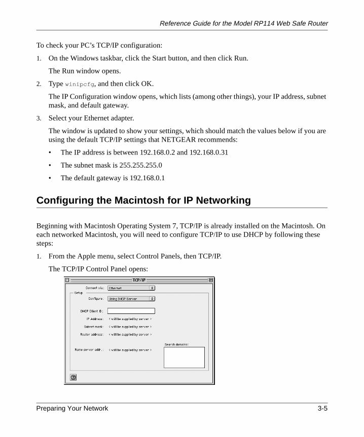
Configuring the Macintosh for IP Networking
Beginning with Macintosh Operating System 7, TCP/IP is already installed on the Macintosheach networked Macintosh, you will need to configure TCP/IP to use DHCP by following thessteps:
1. From the Apple menu, select Control Panels, then TCP/IP.
The TCP/IP Control Panel opens:
Preparing Your Network 3-5

Reference Guide for the Model RP114 Web Safe Router
n byP/IP.
using
witch
2. From the “Connect via” box, select your Macintosh’s Ethernet interface.
3. From the “Configure” box, select Using DHCP Server.
You can leave the DHCP Client ID box empty.
4. Close the TCP/IP Control Panel.
5. Repeat this for each Macintosh on your network.
Verifying TCP/IP Properties (Macintosh)
After your Macintosh is configured and has rebooted, you can check the TCP/IP configuratioreturning to the TCP/IP Control Panel. From the Apple menu, select Control Panels, then TC
The panel is updated to show your settings, which should match the values below if you arethe default TCP/IP settings that NETGEAR recommends:
• The IP Address is between 192.168.0.2 and 192.168.0.31
• The Subnet mask is 255.255.255.0
• The Router address is 192.168.0.1
If you do not see these values, you may need to restart your Macintosh or you may need to sthe “Configure” setting to a different option, then back again to “Using DHCP Server”.
3-6 Preparing Your Network

Reference Guide for the Model RP114 Web Safe Router
able
eenmic
ce ofuld
thod
:
u
s an
ed,
Your Internet Account
For access to the Internet, you need to contract with an Internet service provider (ISP) for asingle-user Internet access account using an external broadband access device such as a cmodem or DSL modem. This modem must be a separate physical box (not a card) and mustprovide an Ethernet port intended for connection to a Network Interface Card (NIC) in a PC.
For a single-user Internet account, your ISP supplies TCP/IP configuration information for onPC. With a typical account, much of the configuration information is dynamically assigned whyour PC is first booted up while connected to the ISP, and you will not need to know that dynainformation.
In order to share the Internet connection among several computers, your router takes the plathe single PC, and you need to configure it with the TCP/IP information that the single PC wonormally use. When the router’s WAN port is connected to the broadband modem, the routerappears to be a single PC to the ISP. The router then allows the PCs on the local network tomasquerade as the single PC to access the Internet through the broadband modem. The meused by the router to accomplish this is called Network Address Translation (NAT) or IPmasquerading.
Login Protocols
Some ISPs require a special login protocol. In this case, you will need to know what type ofprotocol is used, and you will need a login name and password. Some common protocols are
• PPP over Ethernet (PPPoE)Two common PPPoE clients are WinPOET and EnterNet.
• RoadRunnerNot all RoadRunner service areas require a login protocol. If your ISP is RoadRunner, yoshould ask whether your PC must run a RoadRunner login program.
• PPTPPPTP is a VPN client, but it is also used in Europe by Alcatel's ANT system and others aaccount login client.
• BigPond Authentication
After your network and router are configured, the router will perform the login task when needand you will no longer need to login from your PC.
Preparing Your Network 3-7
Reference Guide for the Model RP114 Web Safe Router
ing
hem.youtionore
youre is
anel.
unt
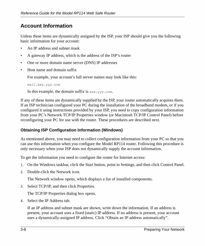
Account Information
Unless these items are dynamically assigned by the ISP, your ISP should give you the followbasic information for your account:
• An IP address and subnet mask
• A gateway IP address, which is the address of the ISP’s router
• One or more domain name server (DNS) IP addresses
• Host name and domain suffix
For example, your account’s full server names may look like this:
mail.xxx.yyy.com
In this example, the domain suffix isxxx.yyy.com .
If any of these items are dynamically supplied by the ISP, your router automatically acquires tIf an ISP technician configured your PC during the installation of the broadband modem, or ifconfigured it using instructions provided by your ISP, you need to copy configuration informafrom your PC’s Network TCP/IP Properties window (or Macintosh TCP/IP Control Panel) befreconfiguring your PC for use with the router. These procedures are described next.
Obtaining ISP Configuration Information (Windows)
As mentioned above, you may need to collect configuration information from your PC so thatcan use this information when you configure the Model RP114 router. Following this proceduonly necessary when your ISP does not dynamically supply the account information.
To get the information you need to configure the router for Internet access:
1. On the Windows taskbar, click the Start button, point to Settings, and then click Control P
2. Double-click the Network icon.
The Network window opens, which displays a list of installed components.
3. Select TCP/IP, and then click Properties.
The TCP/IP Properties dialog box opens.
4. Select the IP Address tab.
If an IP address and subnet mask are shown, write down the information. If an address ispresent, your account uses a fixed (static) IP address. If no address is present, your accouses a dynamically-assigned IP address. Click “Obtain an IP address automatically”.
3-8 Preparing Your Network

Reference Guide for the Model RP114 Web Safe Router
SP’sress.
pears
so
tion.
P
’s DNS
5. Select the Gateway tab.
If an IP address appears under Installed Gateways, write down the address. This is the Igateway address. Select the address and then click Remove to remove the gateway add
6. Select the DNS Configuration tab.
If any DNS server addresses are shown, write down the addresses. If any information apin the Host or Domain information box, write it down. Click Disable DNS.
7. Click OK to save your changes and close the TCP/IP Properties dialog box.
You are returned to the Network window.
8. Click OK.
9. Reboot your PC at the prompt. You may also be prompted to insert your Windows CD.
Obtaining ISP Configuration Information (Macintosh)
As mentioned above, you may need to collect configuration information from your Macintoshthat you can use this information when you configure the Model RP114 router. Following thisprocedure is only necessary when your ISP does not dynamically supply the account informa
To get the information you need to configure the router for Internet access:
1. From the Apple menu, select Control Panels, then TCP/IP.
The TCP/IP Control Panel opens, which displays a list of configuration settings. If the“Configure” setting is “Using DHCP Server”, your account uses a dynamically-assigned Iaddress. In this case, close the Control Panel and skip the rest of this section.
2. If an IP address and subnet mask are shown, write down the information.
3. If an IP address appears under Router address, write down the address. This is the ISP’sgateway address.
4. If any Name Server addresses are shown, write down the addresses. These are your ISPaddresses.
5. If any information appears in the Search domains information box, write it down.
6. Change the “Configure” setting to “Using DHCP Server”.
7. Close the TCP/IP Control Panel.
Preparing Your Network 3-9

Reference Guide for the Model RP114 Web Safe Router
ed to
Ready for Configuration
After configuring all of your PCs for TCP/IP networking and connecting them to the LOCALnetwork of your Model RP114 router, you are ready to access and configure the router. Procethe next chapter.
3-10 Preparing Your Network
fe
owser
TPgrams
Chapter 4Basic Configuration of the Router
This chapter describes how to perform the basic configuration of your Model RP114 Web SaRouter using the Setup Wizard, which walks you through the configuration process for yourInternet connection. This chapter also describes the configuration for content filtering.
Configuring for Internet Access
In order to use the browser-based Web Configuration Manager, your PC must have a web brprogram installed such as Microsoft Internet Explorer or Netscape Navigator. Because theConfiguration Manager uses Java, your Web browser must be Java-enabled and support HTuploads. NETGEAR recommends using Netscape Navigator 3.0 or above. Free browser proare readily available for Windows, Macintosh, or UNIX/Linux.
To configure for Internet access using your browser:
1. Turn on the router and wait for initialization to complete.
Allow at least one minute and verify that the TEST LED is off.
2. Reboot your PC to obtain DHCP configuration from the router.
3. Launch your web browser.
4. In the Address box of your browser, typehttp://192.168.0.1and press ENTER.
Basic Configuration of the Router 4-1

Reference Guide for the Model RP114 Web Safe Router
A login window opens as shown inFigure 4-1below:.
Figure 4-1. Login window
This screen may have a different appearance in other browsers.
5. Typeadmin in the User Name box,1234 in the Password box, and then click OK.
If your router password was previously changed, enter the current password.
6. In the opening screen, shown inFigure 4-2, select WIZARD SETUP.
Figure 4-2. Browser-based configuration main menu
4-2 Basic Configuration of the Router

Reference Guide for the Model RP114 Web Safe Router
in
servers.
7. In the first Wizard screen, enter your account’s Host Name and Domain Name, as shownFigure 4-3below:
Figure 4-3. Browser-based Setup Wizard, first screen
These parameters may be necessary to access your ISP’s services such as mail or newsIf you leave the Domain Name field blank, the router will attempt to learn the domainautomatically from the ISP. If this is not successful, you will need to enter it manually.
Basic Configuration of the Router 4-3

Reference Guide for the Model RP114 Web Safe Router
rnet
PPoE,
use.
s are
h
s are
8. Click on Next to go to the ISP Parameters screen, shown inFigure 4-4below:
Figure 4-4. Browser-based Setup Wizard, second screen
This screen determines whether a login program will be run.
a. If your service provider does not require a login program, leave Encapsulation as Etheand proceed to Step 9.
b. If your service provider uses PPP over Ethernet (PPPoE), select Encapsulation as Pand enter these additional parameters:
• If your connection supports multiple ISPs, enter the Service Name of the one youOtherwise leave Service Name blank.
• Enter the PPPoE login user name and password provided by your ISP. These fieldcase sensitive.
• If you wish to change the login timeout, enter a new value in seconds.
Proceed to Step 9.
c. (Europe) If your service provider uses Alcatel's ANT (ADSL Network Termination) witPPTP as a login method, select Encapsulation as PPTP, and enter these additionalparameters:
• Enter the PPTP login user name and password provided by your ISP. These fieldcase sensitive.
• If you wish to change the login timeout, enter a new value in seconds.
4-4 Basic Configuration of the Router

Reference Guide for the Model RP114 Web Safe Router
f
e
ginager
er.
r IP
ase
• If provided by your ISP, enter your PPTP IP Address and the Server IP Address otheir PPTP Server.
• If provided by your ISP, enter the Connection ID/Name for your service. Otherwisleave this field blank.
Proceed to Step 9.
d. If your service provider is RoadRunner AND you are required to run a RoadRunner loprogram, leave Encapsulation as Ethernet and select Service Type as either RR-Manor RR-Toshiba. Enter these additional parameters:.
• If your cable modem is Toshiba, select RR-Toshiba. Otherwise select RR-Manag• Enter the user name and password provided by your ISP. These fields are case
sensitive.• If RoadRunner provided an authentication server address, enter it as Login Serve
address. Otherwise, leave this field as 0.0.0.0.
Not all RoadRunner regions require a login program. If your region does not require alogin, leave Service Type as Standard.
Proceed to Step 9.
e. Australia only: If your service provider is Telstra Bigpond, select Service Type asBigpond/Telstra, and enter these additional parameters:
• Enter the login user name and password provided by Bigpond. These fields are csensitive.
• If Bigpond provided an authentication server address, enter it as Login Server IPaddress. Otherwise, leave this field as 0.0.0.0.
Basic Configuration of the Router 4-5

Reference Guide for the Model RP114 Web Safe Router
dress
ddress
one oryouou
C
9. Click on Next to go to the final Wizard screen shown inFigure 4-5below.
Figure 4-5. Browser-based Setup Wizard, third screen
This screen provides setup for the following parameters:
a. WAN IP Address Assignment: Unless your ISP has assigned a fixed permanent IP adfor your use, select "Get automatically from ISP". Otherwise, enter your IP Address,Subnet Mask, and the IP Address of your ISP’s gateway router.
b. DNS Server Address Assignment: If you know that your ISP does not automaticallytransmit DNS addresses to the router during login, select “DNS IP Fixed Address” anenter the IP address of the ISP’s Primary DNS Server. If a Secondary DNS Server adis available, enter it also.
A DNS server is a host on the Internet that translates Internet names (such as wwwaddresses) to numeric IP addresses. Typically your ISP transfers the IP addresses oftwo DNS servers to your router during login. If the ISP does not transfer an address,must obtain it from the ISP and enter it manually here. If you enter an address here, yshould reboot your PCs after configuring the router.
c. WAN MAC address: If your ISP allows access by only one specific PC’s Ethernet MAaddress, select "Spoof this PC’s MAC address" and enter the IP address of that PC.
4-6 Basic Configuration of the Router

Reference Guide for the Model RP114 Web Safe Router
ar. If
nheC by
andur
rmed
osoft
cand web
f thebelow
• For convenience, the IP address of the PC you are now using should already appethis is not the PC whose MAC address is to be used, enter that PC's IP address.
• Some ISPs will register the Ethernet MAC address of the network interface card iyour PC when your account is first opened. They will then only accept traffic from tMAC address of that PC. This feature allows your router to masquerade as that Pusing its MAC address.
10. Click on Finish.
11. Click on the NETGEAR website address to test your Internet connection.
If the NETGEAR website does not appear within one minute, refer toChapter 11,“Troubleshooting”.
Your router is now configured to provide Internet access for your network. When your routerPCs are configured correctly, your router automatically accesses the Internet when one of yoLAN devices requires access. It is not necessary to run a dialer application such as Dial-UpNetworking or RoadRunner Login to connect, log in, or disconnect. These functions are perfoby the router as needed.
To access the Internet from any PC connected to your router, launch a browser such as MicrInternet Explorer or Netscape Navigator. You should see the router’s Internet LED blink,indicating communication to the ISP. The browser should begin to display a Web page.
Configuring for Content Filtering
The Model RP114 Web Safe Router provides you with Web content filtering options, plusbrowsing activity reporting and instant alerts via e-mail. Parents and network administratorsestablish restricted access policies based on time-of-day, web and newsgroup addresses anand newsgroup address keywords.
To configure these features of your router, click on the Advanced heading in the Main Menu obrowser interface. From the subheadings shown, click on Content Filter. The tabs describedcontain the settings for content filtering.
Basic Configuration of the Router 4-7

Reference Guide for the Model RP114 Web Safe Router
ail
ame
usedress.
tions:
daily.
sent
In order to receive logs and alerts by email, you must provide your email information in the E-Mtab:
• Mail ServerSpecifies the name of your outgoing (SMTP) mail server. You can enter either the server n(such as mail.myISP.com) or its IP Address. If you leave this box blank, log and alertmessages are not sent via e-mail.
• E-mail ToSpecifies the e-mail address to which logs and alerts are sent. This e-mail address will beas the From address. If you leave this box blank, the log is not sent via e-mail to any add
You can specify that logs are automatically sent to the specified e-mail address with these op
• Send immediate alert upon attempted access to a blocked siteCheck this box if you would like immediate notification of inappropriate access attempts.
• Log ScheduleSpecifies how often to send the logs: Hourly, Daily, Weekly, or When Full.
• Day for Sending LogSpecifies which day of the week to send the log. Relevant when the log is sent weekly or
• Time for Sending LogSpecifies the time of day to send the log, using 23:59 notation. Relevant when the log isdaily.
4-8 Basic Configuration of the Router

Reference Guide for the Model RP114 Web Safe Router
,isup.
dnt
es andThe
a
.
• Time ZoneSpecify your local time zone and click Apply. This setting will be used for the blockingschedule and also for time-stamping log entries.
• Daylight Savings TimeCheck this box if your time zone is currently under daylight savings time.
If the Weekly, Daily or Hourly option is selected and the log fills up before the specified periodthe log is automatically e-mailed to the specified e-mail address. After the log is sent, the logcleared from the router’s memory. If the router cannot e-mail the log file, the log buffer may fillIn this case, the router overwrites the log and discards its contents.
The Model RP114 router uses the Network Time Protocol (NTP) to obtain the current time andate from one of several Network Time Servers on the Internet. This menu displays the curretime.
Keyword
The Model RP114 router allows you to restrict access based on web and newsgroup addressweb and newsgroup address keywords. Up to 255 entries are supported in the Keyword list.Keyword tab is shown below:
To enable keyword blocking, check Enable Keyword Blocking, then click Apply. Be sure thattime period for blocking is specified on the Schedule setup screen.
To add a keyword or domain, type it in the Keyword box, click Add Keyword, then click Apply
Basic Configuration of the Router 4-9

Reference Guide for the Model RP114 Web Safe Router
,
or
ord
tab
xes
ly.
To delete a keyword or domain, select it from the list, click Delete Keyword, then click Apply.
Keyword application examples:
• If the keyword "XXX" is specified, the URL <http://www.badstuff.com/xxx.html> is blockedas is the NNTP newsgroup alt.XXX.
• If the keyword “.com” is specified, only websites with other domain suffixes (such as .edu.gov) can be viewed.
• If you wish to block all Internet browsing access during a scheduled period, enter the keyw“.” and set the schedule in the Schedule menu.
Schedule
The Model RP114 router allows you to specify when blocking will be enforced. The Scheduleis shown below:
• Days to BlockSelect days to block by checking the appropraite boxes. Select Everyday to check the bofor all days. Click Apply.
• Time of Day to BlockSelect a start and end time in 23:59 format. Select All day for 24 hour blocking. Click App
4-10 Basic Configuration of the Router

Reference Guide for the Model RP114 Web Safe Router
you
.
Trusted
The Model RP114 router allows you to specify one Trusted User, which is a PC that will beexempt from blocking and logging. Since the Trusted User will be identified by an IP address,should configure that PC with a fixed IP address.
The Trusted tab is shown below.
To specify a Trusted User, enter that PC’s IP address in the Trusted User box and click Apply
Basic Configuration of the Router 4-11

Reference Guide for the Model RP114 Web Safe Router
to 128and
Logs
The log is a detailed record of what websites you have accessed or attempted to access. Upentries are stored in the log. Log entries will only appear when keyword blocking is enabled,no log entries will be made for the Trusted User.
Log entries are described inTable 4-1
Table 4-1. Log entry descriptions
Field Description
No. The index number of the content filter log entries. 128 entriesare available numbered from 0 to 127. The log will keep therecord of the latest 128 entries.
Time and Entry The time the log entry was recorded. Below the time is the nameor IP address of the website visited or attempted to access.
Source IP The IP address of the initiating device for this log entry.
Action This field displays whether the packet was blocked, forwarded,or neither (BLOCK, FORWARD, or NONE). "NONE" meansthat no action is dictated by this rule.
4-12 Basic Configuration of the Router

Reference Guide for the Model RP114 Web Safe Router
Log viewing buttons are described inTable 4-2
Table 4-2. Log display buttons
Field Description
Previous Page Click this button to view the previous log page.
Refresh Click this button to refresh the log screen.
Clear Click this button to clear the log entries.
Next Page Click this button to view the next log page.
Basic Configuration of the Router 4-13

Reference Guide for the Model RP114 Web Safe Router
4-14 Basic Configuration of the Router

afef the
pter.
l
se
arypaces
ur
Chapter 5Advanced Configuration of the Router
This chapter describes how to configure the advanced features of your Model RP114 Web SRouter. These features can be found by clicking on the Advanced heading in the Main Menu obrowser interface. One advanced feature, Content Filtering, is described in the previous cha
System Settings
The first feature category under the Advanced heading is System settings. These are generapurpose settings.
System Tab
The System Tab contains fields for setting the System (Host) Name and Domain Name. Theparameters may be necessary to access your ISP’s services such as mail or news servers.
• System NameThis is the host or account name given by your ISP for naming your PC. It is often the primemail name of your account.This name can be up to 30 alphanumeric characters long. Sare not allowed, but dashes "-" and underscores "_" are accepted.
• Domain NameThis is the extended domain suffix that follows your ISP server names. For example, if yoISP’s mail server is mail.sfbay.myISP.com, then your Domain Name is sfbay.myISP.com.
Advanced Configuration of the Router 5-1

Reference Guide for the Model RP114 Web Safe Router
n IPcan be
queries
eFor
rd toter the
Dynamic DNS
Your router supports Dynamic Domain Name Service (DDNS). In a Dynamic DNS service, aregistry server provides a public central database where dynamically-assigned IP addressesstored and retrieved by hostname lookup. The Dynamic DNS server also storespassword-protected e-mail addresses along with IP addresses and hostnames and acceptsbased on e-mail addresses.
To utilize this service, you must register with the Dynamic DNS service provider, who will givyou a password or key. At this time, the Model RP114 router only supports DynDNS service.more information, visit www.dyndns.org.
The configuration fields for Dynamic DNS are shown inTable 5-1:
Password
Select the Password tab to change your router’s management password. This is the passwoaccess the router for configuration, not for Internet access. To change the password, first enold password, and then enter the new password twice. Click Apply.
Table 5-1. Dynamic DNS configuration fields
Field Description
Active Use this field to activate or deactivate dynamic DNS registration.
Service Provider Select a dynamic DNS service provider.
Host Name Enter the static host name that will link to your dynamic IP address.
E-Mail Address Enter your email address for administrative contact.
User Enter the user name of your dynamic DNS account.
Password Enter the password of your dynamic DNS account.
Enable Wildcard DynDNS.org allows the use of wildcards in resolving your URL.Enabling the wildcard feature for your host will cause*.yourhost.dyndns.org to be aliased to the same IP address asyourhost.dyndns.org .
5-2 Advanced Configuration of the Router

Reference Guide for the Model RP114 Web Safe Router
r
n IP,ss is the
hese
LAN Setup
The second feature category under the Advanced heading is LAN Setup. This menu allowsconfiguration of LAN IP services such as DHCP and RIP. From the Main Menu of the browseinterface, under Advanced, click on LAN to view the LAN Setup menu, shown inFigure 5-1
Figure 5-1. LAN Setup Menu
DHCP
The Model RP114 router have the capability to act as a DHCP server, allowing them to assigDNS, and default gateway addresses to attached PCs. The assigned default gateway addreLAN address of the router. IP addresses will be assigned to the attached PCs from a pool ofaddresses specified in this menu. Each pool address is tested before it is assigned to avoidduplicate addresses on the LAN.
See“IP Configuration by DHCP” on page B-10for an explanation of DHCP and informationabout how to assign IP addresses for your network.
For most applications, the default DHCP and TCP/IP settings of the router are satisfactory. Tdefault settings are:
• DHCP server enabled with 32 client addresses starting from 192.168.0.1.
Advanced Configuration of the Router 5-3

Reference Guide for the Model RP114 Web Safe Router
Table 5-2lists and describes the fields to use for setting up DHCP parameters..
LAN TCP/IP
Table 5-3lists and describes the fields to use for setting up TCP/IP parameters for the LAN...
Table 5-2. DHCP Setup Fields
Field Description
DHCP Server: If this box is checked, the router acts as a DHCP server.If this box is cleared, the router’s DHCP server is disabled.
Pool Starting Address The beginning of the range of IP addresses to assign.
Count The number of sequential addresses available for assignment toattached hosts. The maximum is 32.
Primary DNS Server If you want the router to provide the Primary DNS Server address toattached hosts, enter the DNS address in this field. If this field is 0.0.0.0,the router assigns its own address as DNS Server, and performs a DNSProxy if it can obtain a DNS address from the ISP.
Secondary DNS Server If you want the router to assign the Secondary DNS Server addressto attached hosts, enter the address in this field.
Table 5-3. LAN TCP/IP Setup Fields
Field Description
TCP/IP Setup:
IP Address Enter the IP address of the LAN interface of the router in dotted-decimalnotation (four 8-bit numbers, between 0 and 255, separated by periods,for example, 192.168.0.1). Every device on the TCP/IP network musthave a unique IP address.
IP Subnet Mask An IP address consists of two parts, the network ID and the host ID. TheIP Subnet Mask specifies the network ID portion of the address, writtenin dotted-decimal notation. The router automatically calculates this maskfor the class of the IP address that you assign. Unless you have aspecial need for subnetting, use the default subnet mask calculated bythe router. All hosts on the LAN segment should use the same mask.
5-4 Advanced Configuration of the Router

Reference Guide for the Model RP114 Web Safe Router
to
RIP Direction This parameter determines how the router handles RIP (RoutingInformation Protocol). RIP allows the router to exchange routinginformation with other routers. If set to None (default), the router doesnot participate in any RIP exchange with other routers. If set to Both, therouter broadcasts the routing table of the router on the LAN andincorporates RIP broadcasts by other routers into its routing table. If setto In Only, the router broadcasts its routing table on the LAN. If set toOut Only, the router broadcasts its routing table, but it ignores any RIPbroadcast packets that it receives. Usually, you should leave thisparameter at the default (None).
RIP Version This field determines the format and broadcasting method of any RIP(Routing Information Protocol) transmissions by the router. The followingRIP options are supported by the Model RP114 router:• RIP-1—The router sends RIP-1 messages only.• RIP-2B—The router sends RIP-2 messages in broadcast format.• RIP-2M—The router sends RIP-2 messages in multicast format.For most applications, the recommended version is RIP-1.
Multicast Some streaming media applications (e.g. Cisco IP/TV, RealPlayer) nowsupport IP Multicast. To enable Multicast routing, select either IGMP-v1or IGMP-v2.
Note: If you change the LAN IP address of the router while connected through thebrowser or Telnet, you will be disconnected. You must then open a new connectionthe new IP address and log in again.
Table 5-3. LAN TCP/IP Setup Fields (continued)
Field Description
Advanced Configuration of the Router 5-5

Reference Guide for the Model RP114 Web Safe Router
ernet,lable
acketTPt the
allyat
Configuring for Port Forwarding to Local Servers
Although the router causes your entire local network to appear as a single machine to the Intyou can make local servers for different services (for example, FTP or HTTP) visible and avaito the Internet. This is done using the PORTS menu. From the Main Menu of the browserinterface, under Advanced, click on PORTS to view the port forwarding screen, shown inFigure 5-2
Figure 5-2. Port Forwarding Menu
Requested services are identified by port numbers in an incoming IP packet. For example, a pthat is sent to the external IP address of your router and destined for port number 80 is an HT(Web server) request, and port 21 is an FTP request. Examples of port numbers are shown atop of the PORTS menu, although you are not limited to these choices. See IETF RFC1700,“Assigned Numbers,” for port numbers for common protocols..
Note: Many residential broadband ISP accounts do not allow you to run any serverprocesses (such as a Web or FTP server) from your location. Your ISP may periodiccheck for servers and may suspend your account if it discovers any active servicesyour location. If you are unsure, refer to the Acceptable Use Policy of your ISP.
5-6 Advanced Configuration of the Router

Reference Guide for the Model RP114 Web Safe Router
oncan
nter
e thewn in
the IPnternetd IPdress.
nge
oted.than
Use the PORTS menu to configure the router to forward incoming protocols to IP addressesyour local network based on the port number. In addition to servers for specific protocols, youalso specify a Default (also called DMZ) Server to which all other incoming protocols areforwarded. To configure port forwarding to a local server:
1. Enter a port number in an unused Start Port box.
2. To forward only one port, enter it again in the End Port box. To specify a range of ports, ethe last port to be forwarded in the End Port box.
3. Enter the IP address of the local server in the corresponding Server IP Address box.
4. Click Apply at the bottom of the menu.
Local Web and FTP Server Example
If a local PC, with a private address of 192.168.0.33, acts as a Web and FTP server, configurPORTS menu to forward ports 80 (HTTP) and 21 (FTP) to local address 192.168.0.33 as shoTable 5-4.
In order for a remote user to access this server from the Internet, the remote user must knowaddress that has been assigned by your ISP. If this address is 172.16.1.23, for example, an Iuser can access your Web server by directing the browser to http://172.16.1.23. The assigneaddress can be found in the Maintenance Status Menu, where it is shown as the WAN IP Ad
Some considerations for this application are:
• If your account’s IP address is assigned dynamically by your ISP, the IP address may chaperiodically as the DHCP lease expires.
• If the IP address of the local PC is assigned by DHCP, it may change when the PC is reboTo avoid this, change the configuration of your PCs to use fixed private addresses ratherDHCP-assigned addresses.
Table 5-4. Port Table Entries (Example)
Port # Server IP Address
Default 0.0.0.0
80 (HTTP) 192.168.0.33
21 (FTP) 192.168.0.33
Advanced Configuration of the Router 5-7

Reference Guide for the Model RP114 Web Safe Router
n this
ses,ult indress
needsuch
the
• Local PCs must access the local server using the PCs’ local LAN address (192.168.0.33 iexample). Attempts by local PCs to access the server using the external IP address(172.16.1.23 in this example) will fail.
Local Game Host or Videoconference Example
Some online games and videoconferencing applications are incompatible with NAT. TheModel RP114 router is programmed to recognize some of these applications and to workproperly with them, but there are other applications that may not function well. In some caone local PC can run the application properly if that PC’s IP address is entered as the defathe PORTS Menu. If one local PC acts as a game or videoconference host, enter its IP adas the default.
Static Routes
The fourth feature category under the Advanced heading is Static Route, which allowsconfiguration of additional routing information. Under normal circumstances, the router hasadequate routing information after it has been configured for Internet access, and you do notto configure additional static routes. You must configure static routes only for unusual casesas multiple routers or multiple IP subnets located on your network.
From the Main Menu of the browser interface, under Advanced, click on Static Route to viewStatic Route menu, shown inFigure 5-3.
Figure 5-3. Static Route Summary Table
5-8 Advanced Configuration of the Router
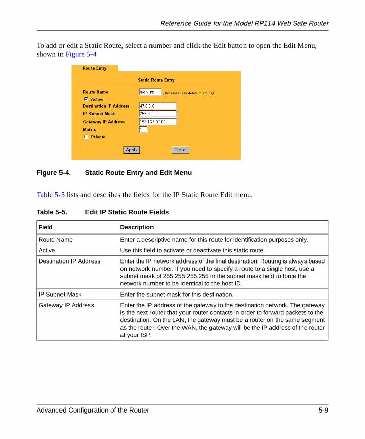
Reference Guide for the Model RP114 Web Safe Router
u,
To add or edit a Static Route, select a number and click the Edit button to open the Edit Menshown inFigure 5-4Figure 5-4. Static Route Entry and Edit Menu
Table 5-5lists and describes the fields for the IP Static Route Edit menu.
Table 5-5. Edit IP Static Route Fields
Field Description
Route Name Enter a descriptive name for this route for identification purposes only.
Active Use this field to activate or deactivate this static route.
Destination IP Address Enter the IP network address of the final destination. Routing is always basedon network number. If you need to specify a route to a single host, use asubnet mask of 255.255.255.255 in the subnet mask field to force thenetwork number to be identical to the host ID.
IP Subnet Mask Enter the subnet mask for this destination.
Gateway IP Address Enter the IP address of the gateway to the destination network. The gatewayis the next router that your router contacts in order to forward packets to thedestination. On the LAN, the gateway must be a router on the same segmentas the router. Over the WAN, the gateway will be the IP address of the routerat your ISP.
Advanced Configuration of the Router 5-9

Reference Guide for the Model RP114 Web Safe Router
e
wastworke
Static Route Example
As an example of when a static route is needed, consider the following case:
• Your primary Internet access is through a cable modem to an ISP.
• You have an ISDN router on your home network for connecting to the company wheryou are employed. This router’s address on your LAN is 192.168.0.100.
• Your company’s network is 134.177.0.0.
When you first configured your router, two implicit static routes were created. A default routecreated with your ISP as the gateway, and a second static route was created to your local nefor all 192.168.x.x addresses. With this configuration, if you attempt to access a device on th134.177.0.0 network, your router will forward your request to the ISP. The ISP forwards yourrequest to the company where you are employed, and the request will likely be denied by thecompany’s firewall.
Metric Enter the cost in ‘hops’ of transmission for routing purposes. IP routing useshop counts as the measurement of cost, with a minimum of 1 for directlyconnected networks. Enter a number that approximates the cost for this link.The number does not have to be precise, but it must be between 1 and 16. Inpractice, 2 or 3 is usually a good number.
Private Use this field to determine whether the router includes the route to thisremote node in its RIP broadcasts. If set to Yes, this route is kept private andnot included in any RIP broadcast. If set to No, the route to this remote nodeis propagated to other hosts through RIP broadcasts.
Table 5-5. Edit IP Static Route Fields (continued)
Field Description
5-10 Advanced Configuration of the Router

Reference Guide for the Model RP114 Web Safe Router
essed
s to
In this case you must define a static route, telling your router that 134.177.0.0 should be accthrough the ISDN router at 192.168.100. The static route would look likeFigure 5-5.
Figure 5-5. Static Route Example
In this example:
• The Destination IP Address and IP Subnet Mask fields specify that this static route applieall 134.177.x.x addresses.
• The Gateway IP Address fields specifies that all traffic for these addresses should beforwarded to the ISDN router at 192.168.0.100.
• A Metric value of either 1 or 2 will work.
• Private is selected only as a precautionary security measure in case RIP is activated.
Advanced Configuration of the Router 5-11

Reference Guide for the Model RP114 Web Safe Router
5-12 Advanced Configuration of the Router

nu of
hethe
Chapter 6Maintenance
This chapter describes how to use the maintenance features of your Model RP114 Web SafeRouter. These features can be found by clicking on the Maintenance heading in the Main Methe browser interface.
System Status
The System Status menu provides a limited amount of status and usage information. From tMain Menu of the browser interface, click on Maintenance, then select System Status to viewSystem Status screen, shown inFigure 6-1
.
Figure 6-1. System Status screen
Maintenance 6-1

Reference Guide for the Model RP114 Web Safe Router
This screen shows the following parameters:
Table 6-1. Menu 3.2 - System Status Fields
Field Description
System Name This field displays the Host Name assigned to the router.
Router Firmware Version This field displays the router firmware version.
WAN Port These parameters apply to the Internet (WAN) port of the router.
IP Address This field displays the IP address being used by the Internet (WAN) portof the router. If no address is shown, the router cannot connect to theInternet.
IP Subnet Mask This field displays the IP Subnet Mask being used by the Internet (WAN)port of the router.
DHCP If set to None, the router is configured to use a fixed IP address on theWAN.If set to Client, the router is configured to obtain an IP addressdynamically from the ISP.
LAN Port These parameters apply to the Local (WAN) port of the router.
IP Address This field displays the IP address being used by the Local (LAN) port ofthe router. The default is 192.168.0.1
IP Subnet Mask This field displays the IP Subnet Mask being used by the Local (LAN)port of the router. The default is 255.255.255.0
DHCP If set to None, the router will not assign IP addresses to local PCs on theLAN.If set to Server, the router is configured to assign IP addresses to localPCs on the LAN.
6-2 Maintenance

Reference Guide for the Model RP114 Web Safe Router
Click on the “Show Statistics” button to display router usage statistics, as shown inFigure 6-2below:
Figure 6-2. Router Statistics screen
This screen shows the following statistics:.
Table 6-2. Router Statistics Fields
Field Description
Port The statistics for the WAN (Internet) and LAN (local) ports. For each port, the screendisplays:
Status The link status of the port.
TxPkts The number of packets transmitted on this port since reset or manual clear.
RxPkts The number of packets received on this port since reset or manual clear.
Collisions The number of collisions on this port since reset or manual clear.
Tx B/s The current line utilization—percentage of current bandwidth used on this port.
Tx B/s The average line utilization —average CLU for this port.
Up Time The time elapsed since this port acquired link.
System up Time The time elapsed since the last power cycle or reset.
Poll Interval Specifies the intervals at which the statistics are updated in this window. Click on Stopto freeze the display.
Maintenance 6-3

Reference Guide for the Model RP114 Web Safe Router
CPP
stP
aded
ile
port
click
DHCP Table
The DHCP Table shows all IP address assignments that have been made by the router’s DHserver. From the Main Menu of the browser interface, click on Maintenance, then select DHCTable to view the table, shown inFigure 6-3
Figure 6-3. DHCP Table
For each PC client, the table shows the IP address, Ethernet MAC address, and NetBIOS HoName. Note that if the router is rebooted, the table data is lost until each PC renews its DHClease.
Software Upgrade
The routing software of the Model RP114 router is stored in FLASH memory, and can be upgras new software is released by NETGEAR. Upgrade files can be downloaded from Netgear'swebsite. If the upgrade file is compressed (.ZIP file), you must first extract the binary (.BIN) fbefore sending it to the router. The upgrade file can be sent to the router using your browser.
Note: The Web browser used to upload new firmware into the Model RP114 router must supHTTP uploads. NETGEAR recommends using Netscape Navigator 3.0 or above.
To reach the Upgrade menu, click Maintenance from the navigation bar on the left, and thenthe Upgrade heading. To upload new firmware:
1. Download and unzip the new software file from NETGEAR.
2. In the Software Upgrade menu, click the Browse button and browse to the location of thebinary (.BIN) upgrade file
3. Click Upload.
6-4 Maintenance

Reference Guide for the Model RP114 Web Safe Router
theis
the
ace,ons.
a file
actr
youroad
by
will
Note: When uploading software to the Model RP114 router, it is important not to interruptWeb browser by closing the window, clicking a link, or loading a new page. If the browserinterrupted, it may corrupt the software. When the upload is complete, your router willautomatically restart.
In some cases, you may need to reconfigure the router after upgrading.
Configuration File Management
The configuration settings of the Model RP114 router are stored within the router in aconfiguration file. This file can be saved (backed up) to a user’s PC, retrieved (restored) fromuser’s PC, or cleared to factory default settings.
To manage the configuration file, click on Maintenance in the Main Menu of the browser interfthen select Files. Three submenu tabs are available, and are described in the following secti
Restore and Backup the Configuration
The Restore and Backup tabs in the Maintenance Files menu allow you to save and retrievecontaining your router’s configuration settings.
To save your settings, select the Backup tab. Click the Backup button. Your browser will extrthe configuration file, named‘rom-0’, from the router and will prompt you for a location on youPC to store the file.
To restore your settings, select the Restore tab. Enter the full path to the configuration file onPC or click the Browse button to browse to the file. When you have located it, click on the Uplbutton to send the file to the router. The router will then reboot automatically.
Erase the Configuration
It is sometimes desirable to restore the router to a known blank condition. This can be doneusing the Erase function, which will restore all factory settings. After an erase, the router'spassword will be 1234, the LAN IP address will be 192.168.0.1, and the router's DHCP clientbe enabled.
To erase the configuration, click the Erase tab, then click the Erase button on the screen.
Maintenance 6-5

Reference Guide for the Model RP114 Web Safe Router
To restore the factory default configuration settings without knowing the login password or IPaddress, you must use the Default Reset button on the rear panel of the router. See“Using theDefault Reset button“ on page 11-8.
6-6 Maintenance

ors of
IP
and
Chapter 7Using the Manager Interface for Initial Router
Configuration
This chapter contains information about basic configuration for your Model RP114 Web SafeRouter using the internal Manager interface. The initial configuration consists of:
– accessing the Manager,
– naming the router,
– and setting up the LAN interface, including DHCP parameters to be assigned to theattached PCs.
After you have performed basic router configuration, proceed toChapter 8, “Using the ManagerInterface to Configure the Router for Internet Access,” andChapter 10, “Configuring Filters,” toconfigure Internet access and additional features.
Connecting for Configuration
The Manager interface is accessible by a Telnet call from any TCP/IP workstation on the LANthe remote network. In order to use the Telnet Protocol, you must know the current IP addresthe router. The router is shippped with a default address of 192.168.0.1.
To establish a Telnet connection from the LAN, you must set up your workstation to reach theaddress of the router by doing one of the following:
• Set your workstation to an IP address on the currently programmed subnet of the router.
Note: You can also use the browser-based setup to configure most router features,later use the Manager interface to configure more advanced features.
Using the Manager Interface for Initial Router Configuration 7-1

Reference Guide for the Model RP114 Web Safe Router
ss the
lnet
tes
e for
OR
• Add a route to the static routing table of the workstation to indicate that the router can bereached through the local LAN port.
To access the router by Telnet from a Windows PC:
1. From the Windows toolbar, select Start.
2. Select Run...
3. In the Open field, type:
telnet 192.168.0.1
4. Click on OK.
The router should respond with a “Password:” prompt. Type the current password to acceManager interface. The default password is 1234.
.When using Telnet, consider the following restrictions:
• Single administrator
To prevent confusion and discrepancy on the configuration, the router allows only one Teconnection at any time.
• System timeout
When you are connected to the router through Telnet, there is a system timeout of 5 minu(300 seconds). If you are not configuring the device and leave it inactive for this timeoutperiod, the router automatically disconnects from the Telnet session. An exception is madMenu 24.1, which displays current status and statistics. This menu will not time out.
7-2 Using the Manager Interface for Initial Router Configuration

Reference Guide for the Model RP114 Web Safe Router
heST
Using the Manager Interface
Login
When power is first applied to the router, several internal tests are performed by the router. Trouter will not accept a Telnet connection until initialization is complete as indicated by the TELED turning off. Log in to the Manager interface:
1. Open a Telnet session as described in the previous section, and log in.
The Main Menu (Figure 7-1) of the Manager will appear.
Figure 7-1. Manager Main Menu
RP114 Main Menu
Getting Started Advanced Management
1. General Setup 21. Filter Set Configuration
2. WAN Setup
3. LAN Setup 23. System Password
4. Internet Access Setup 24. System Maintenance
Advanced Applications
11. Remote Node Setup
12. Static Routing Setup
15. SUA Server Setup
99. Exit
Using the Manager Interface for Initial Router Configuration 7-3

Reference Guide for the Model RP114 Web Safe Router
Navigating the Manager
The Manager is the interface that you use to configure your router.Table 7-1lists and describes thecommands that enable you to navigate through the Manager menus.
Manager Menu Summary
Table 7-2describes the top-level Manager menus.
Table 7-1. Manager Menu Commands
Action Description
Move forward toanother menu
Enter the number of the submenu and press [Enter].
Move back to aprevious menu
Press [Esc]. The only exception is the Main Menu, where typing 99 is the onlymethod to exit from the Manager.
Move the cursor Press [Enter]. You can also use the Up and Down keys to move to the previous andnext fields, respectively.
Enter information There are two types of fields for entering selected parameters. The first requires youto enter the appropriate information. The second gives you options to choose from.When choosing options, press the space bar to toggle through the available options.
Required fields Some of the fields in the Manager are essential in order to configure the router. Therequired fields initially show a question mark (?), indicating that the information mustbe filled in before that menu can be saved.
N/A fields Some of the fields in the Manager show N/A, meaning the option is not available.
Save yourconfiguration
Press [Enter] when prompted to press ENTER to confirm or ESC to cancel. In mostcases, saving the data on the screen takes you to the previous menu.
Table 7-2. Manager Menu Summary
Number Menu Title Description
1 General Setup Specify a router name.
2 WAN Setup Set full/half duplex to the external wide area network (WAN)connection. This connection is typically a broadband modemconnected to the WAN port of the router. Also allows selection of theMAC address.
3 LAN Setup Configure the local area network (LAN) parameters, including IPaddress and DHCP operation.
7-4 Using the Manager Interface for Initial Router Configuration

Reference Guide for the Model RP114 Web Safe Router
4 Internet Access Setup Set up a basic Internet connection.
11 Remote Node Setup Configure additional parameters of the Internet connection
12 Static Routing Setup Manually configure static routes. The router supports eight staticroutes.
15 SUA Server Setup Configure forwarding of specific incoming service requests to localhosts.
21 Filter Set Configuration Set up filters to be used in Menu 3 and Menu 11 to provide securityand traffic control.
23 System Password Change password for Manager access.
24 System Maintenance Provide system status, diagnostics, and firmware upload.
99 Exit Exit from the Manager.
Table 7-2. Manager Menu Summary (continued)
Number Menu Title Description
Using the Manager Interface for Initial Router Configuration 7-5

Reference Guide for the Model RP114 Web Safe Router
e
Ife set tos are
sis:
General Setup Menu
The General Setup Menu contains administrative and system-related information, such as throuter name.
To enter administrative and system-related information:
1. Enter 1 from the Main Menu to display Menu 1 - General Setup, as illustrated inFigure 7-2.
Figure 7-2. Menu 1 - General Setup
2. In the System Name field, enter a name for identifying the router.
For identification purposes, choose a descriptive name for the router, such as MyRP114.your ISP has assigned a host name for your PC, the System Name in some cases must bthe host name. The System Name can include up to 30 alphanumeric characters. Spacenot allowed, but dashes ( - ) and underscores ( _ ) are acceptable.
3. (Optional) In the Domain Name field, enter the domain name of your Internet service.
The Domain Name may be helpful in accessing some of the services of your ISP, such aemail, news servers and customer support. If your account’s full server names look like th
mail.xxx.yyy.com
your domain name is xxx.yyy.com.
4. (Optional) Configure for Dynamic DNS.
If you wish to use Dynamic DNS, refer to“Dynamic DNS“ on page 8-17.
Menu 1 - General Setup
System Name = MyRP114
Domain Name: santaclara.gearguy.com
Configure Dynamic DNS= No
Press ENTER to Confirm or ESC to cancel:
7-6 Using the Manager Interface for Initial Router Configuration

Reference Guide for the Model RP114 Web Safe Router
uch as
WAN Setup
Menu 2 enables you to configure the 10 Mbps Ethernet port to a broadband modem device, sa cable or DSL modem. This port is labeled WAN on the front panel of the router.
Figure 7-3shows Menu 2 - WAN Setup.
Figure 7-3. Menu 2 - WAN Setup
Table 7-3lists and describes the fields for Menu 2 - WAN Setup.
Table 7-3. WAN Setup Fields
Field Description
MAC Address The MAC Address is the 48-bit Ethernet address of the router’s INTERNET port.
Assigned By Set to Factory default to use the router’s internal globally unique MAC address.Set to ‘IP address attached on LAN’ to acquire and substitute the MAC address ofone of your PCs on the local network. Some ISPs will only accept traffic from theMAC address of one PC. This feature allows your router to masquerade as that PCby using its MAC address.
IP Address If you selected IP address attached on LAN in the previous field, you must specifythe IP address of the local PC with the MAC address to be used by the router.
Menu 2 - WAN Setup
MAC Address:
Assigned By= Factory default
IP Address= N/A
Press ENTER to Confirm or ESC to cancel:
Using the Manager Interface for Initial Router Configuration 7-7

Reference Guide for the Model RP114 Web Safe Router
IP
.Youu.
LAN Setup
Menu 3 enables you to configure the Ethernet LAN parameters, including filters, DHCP, andaddress information. These parameters specify the behavior of the router’s local port.
1. From the Main Menu, enter 3 to display Menu 3 - LAN Setup (Figure 7-4).
Figure 7-4. Menu 3 - LAN Setup
2. Select one of the following submenus:
• Menu 3.1 LAN Port Filter Setup
• Menu 3.2 TCP/IP and DHCP Setup
Refer to the following sections for descriptions of these submenus. Refer toTable 7-1onpage7-4 for information about navigating through the menus.
LAN Port Filter Setup Menu
The LAN Port Filter Setup Menu allows you to apply filter sets to control your Ethernet trafficFilters are used to block certain packets, to reduce traffic, and to prevent security breaches.must first create these filter sets using Menu 21, and then apply them by number in this menRefer toChapter 10, “Configuring Filters,” for more information about configuring and applyingfilters.
Menu 3 - LAN Setup
1. LAN Port Filter Setup
2. TCP/IP and DHCP Setup
Enter Menu Selection Number:
7-8 Using the Manager Interface for Initial Router Configuration

Reference Guide for the Model RP114 Web Safe Router
.
NS,aytested
hese
tntries
t,IP
Table 7-4lists and describes the interface and filter choices in the LAN Port Filter Setup menu
TCP/IP and DHCP Setup
The Model RP114 router has the capability to act as a DHCP server, allowing it to assign IP, Dand default gateway addresses to attached PCs or workstations. The assigned default gatewaddress is the LAN address of the router, as set in the TCP/IP section. Each pool address isbefore it is assigned to avoid duplicate addresses on the LAN.
If you are setting up your network for the first time, read about IP addresses starting with“IPAddresses and the Internet” on page B-2and“IP Configuration by DHCP” on page B-10for anexplanation of DHCP and information about how to assign IP addresses for your network.
For most applications, the default DHCP and TCP/IP settings of the router are satisfactory. Tdefault settings are:
• LAN IP address 192.168.0.1 with subnet mask 255.255.255.0.
• DHCP server enabled with 32 client addresses starting from 192.168.0.1.
• DNS Proxy enabled (the router address is assigned as a DNS server).
Table 7-5lists and describes the fields to use for setting up TCP/IP and DHCP parameters inMenu 3.2. When you finish entering information in all of the fields, press [Enter] at the prompPress ENTER to Confirm. Your selections are saved. Press [Esc] at any time to cancel the eyou have made.
Table 7-4. Menu 3.1 - LAN Port Filter Setup Fields
Field Description
Input and Output Filter Sets Enter filter sets by number to filter packets coming from the LAN (Input)or going out to the LAN (Output).
Protocol Filters Enter the numbers of one or more IP filter sets created in Menu 21.
Device Filters Enter the numbers of one or more generic filter sets created in Menu 21.
Note: If you change the LAN IP address of the router while connected through Telneyou lose the Telnet session. You must then open a new Telnet connection to the newaddress and log in again.
Using the Manager Interface for Initial Router Configuration 7-9

Reference Guide for the Model RP114 Web Safe Router
.
Table 7-5. Menu 3.2 - TCP/IP and DHCP Setup Fields
Field Description
DHCP: If set to Server, the router acts as a DHCP server.If set to None, the router’s DHCP server is disabled.
DHCP Configuration:
Client IP Pool StartingAddress
This field is the beginning of the range of addresses to assign.
Size of Client IP Pool This field is the number of sequential addresses available forassignment to attached hosts. The maximum is 32.
Primary DNS Server If you want the router to provide the Primary DNS Server address toattached hosts, enter the DNS address in this field. If this field is 0.0.0.0,the router assigns its own address as DNS Server, and performs a DNSProxy if it can obtain a DNS address from the ISP.
Secondary DNS Server If you want the router to assign the Secondary DNS Server addressto attached hosts, enter the address in this field.
TCP/IP Setup:
IP Address Enter the IP address of the LAN interface of the router in dotted-decimalnotation (four 8-bit numbers, between 0 and 255, separated by periods,for example, 192.168.0.1). Every device on the TCP/IP network musthave a unique IP address.
IP Subnet Mask An IP address consists of two parts, the network ID and the host ID. TheIP Subnet Mask specifies the network ID portion of the address, writtenin dotted-decimal notation. The router automatically calculates this maskfor the class of the IP address that you assign. Unless you have aspecial need for subnetting, use the default subnet mask calculated bythe router. All hosts on the LAN segment should use the same mask.
RIP Direction This parameter determines how the router handles RIP (RoutingInformation Protocol). RIP allows the router to exchange routinginformation with other routers. If set to None (default), the router doesnot participate in any RIP exchange with other routers. If set to Both, therouter broadcasts the routing table of the router on the LAN andincorporates RIP broadcasts by other routers into its routing table. If setto In Only, the router broadcasts its routing table on the LAN. If set toOut Only, the router broadcasts its routing table, but it ignores any RIPbroadcast packets that it receives. Usually, you should leave thisparameter at the default (None).
7-10 Using the Manager Interface for Initial Router Configuration

Reference Guide for the Model RP114 Web Safe Router
Manager Password Setup
For security, you should change the Manager password from the default value of 1234.
To change the Manager password:
1. Select option 23, System Password, from the main menu.
Menu 23 - System Password opens (Figure 7-5).
Figure 7-5. Menu 23 - System Password
RIP Version This field determines the format and broadcasting method of any RIP(Routing Information Protocol) transmissions by the router. The followingRIP options are supported by the Model RP114 router:• RIP-1—The router sends RIP-1 messages only.• RIP-2B—The router sends RIP-2 messages in broadcast format.• RIP-2M—The router sends RIP-2 messages in multicast format.For most applications, the recommended version is RIP-1.
Multicast Some streaming media applications (e.g. Cisco IP/TV, RealPlayer) nowsupport IP Multicast. To enable Multicast routing, select either IGMP-v1or IGMP-v2.
Table 7-5. Menu 3.2 - TCP/IP and DHCP Setup Fields (continued)
Field Description
Menu 23 - System Password
Old Password= ?
New Password= ?
Retype to confirm= ?
Enter here to CONFIRM or ESC to CANCEL:
Using the Manager Interface for Initial Router Configuration 7-11

Reference Guide for the Model RP114 Web Safe Router
ction.
2. Enter your previous system password, and press [Enter].
3. Enter your new system password, and press [Enter].
4. Enter your new system password again for confirmation, and press [Enter].
You must enter this new password when you want to access the Manager by a Telnet conne
If you lose or forget the Manager password, you must clear the configuration of the router asdescribed inChapter 11, “Troubleshooting.” Clearing the configuration causes the Managerpassword to revert to the default, 1234.
7-12 Using the Manager Interface for Initial Router Configuration

essr to
plied
Chapter 8Using the Manager Interface to Configure the
Router for Internet Access
This chapter describes how to configure your Model RP114 Web Safe Router for Internet accusing the internal Manager interface. For information about using the Manager interface, refeChapter 7, “Using the Manager Interface for Initial Router Configuration.”
Internet Access Configuration
You can configure the router for basic access to your Internet service provider (ISP) usingManager Menu 4, Internet Access Setup. The configuration information required is either supdirectly by your ISP or must be obtained from your preconfigured PC as described in“ObtainingISP Configuration Information (Windows)” on page 3-8. Additional configuration parameters areavailable in Menu 11, Remote Node Setup.
To configure your router for Internet access:
1. Enter 4 from the Main Menu to display Menu 4 - Internet Access Setup.
Menu 4 - Internet Access Setup opens (Figure 8-1).
Using the Manager Interface to Configure the Router for Internet Access 8-1

Reference Guide for the Model RP114 Web Safe Router
to
ramthehed
.
d to
ram:
Figure 8-1. Menu 4 - Internet Access Setup
2. Enter the name of your ISP in the ISP’s Name field (for example, myISP).
This information is required for identification purposes only.
3. If your ISP uses PPP over Ethernet (PPPoE), use the space bar to toggle EncapsulationPPPoE. Otherwise, leave it as Ethernet.
PPP over Ethernet (PPPoE) is a type of connection that requires the use of a dialer progsuch as Microsoft Dial-Up Networking to access your DSL or cable modem. In this case,router will perform this function, and it will not be necessary to run the dialer on your attacPCs.
a. If your connection supports multiple ISPs, enter the Service Name of the one you useOtherwise, leave Service Name blank.
b. Enter your account’s login name as My Login.
c. Enter your account’s password as My Password.
4. If you selected Ethernet Encapsulation, use the space bar to toggle the Service Type fieleither RoadRunner or Standard.
This field determines whether the RoadRunner login program will be run. If your serviceprovider is not RoadRunner or if your RoadRunner region does not require the login prog
Menu 4 - Internet Access Setup
ISP's Name= ChangeMe
Encapsulation= Ethernet
Service Type= Standard
My Login= N/A
My Password= N/A
Login Server IP= N/A
IP Address Assignment= Dynamic
IP Address= N/A
IP Subnet Mask= N/A
Gateway IP Address= N/A
Single User Account= Yes
Press ENTER to Confirm or ESC to Cancel:
8-2 Using the Manager Interface to Configure the Router for Internet Access

Reference Guide for the Model RP114 Web Safe Router
ram:
dress.
r PC,dressas
ter
etup.
a. Select Standard.
If your Service Type is RoadRunner and your RoadRunner region requires the login prog
a. Select the RoadRunner login program used in your region.
b. Enter the login name and password provided by RoadRunner.
5. If RoadRunner provided an authentication server address, enter it as Login Server IP adOtherwise, leave this field as 0.0.0.0.
6. Use the space bar to toggle the IP Address Assignment field to Static or Dynamic.
If your service provider has assigned you an IP address to be manually configured in youselect Static. In this case, enter your assigned IP address, subnet mask, and gateway ad(the address of the ISP’s router). If you do not know the gateway address, leave this field0.0.0.0.
7. Use the space bar to toggle the Single User Account field to Yes.
8. Press [Enter] at the Press ENTER to Confirm... prompt to confirm your selections.
You can press [Esc] at any time to cancel your selections. When you save this menu, the rouautomatically creates a default static route to the ISP.
Remote Node Setup Menu
Additional settings for Internet Access connection are provided in Menu 11 - Remote Node STo access Menu 11:
1. Enter 11 from the Main Menu to display Menu 11 - Remote Node Setup.
Menu 11.1 - Remote Node Profile opens as shown inFigure 8-2.
Using the Manager Interface to Configure the Router for Internet Access 8-3

Reference Guide for the Model RP114 Web Safe Router
enter
Figure 8-2. Menu 11.1 - Remote Node Profile
2. Edit the remote node settings with the desired changes.
3. At the bottom of Menu 11.1, press Enter to save Menu 11.1.
Press [Esc] at any time to cancel your selections.
Table 8-1lists and describes the fields in the Remote Node Profile menu and explains how tothe information in each field.
Table 8-1. Remote Node Profile Fields
Field Description
Rem Node Name This field is required. Enter a descriptive name for the remote node (for example,MyOffice). This field supports up to eight characters. .
Active Press the space bar to toggle between Yes and No. When a remote node isdeactivated, it has no effect on the operation of the router, even though it is still keptin the database and can be activated in the future. Deactivated nodes aredisplayed with a minus sign (-) preceding the name in Menu 11.
Menu 11.1 - Remote Node Profile
Rem Node Name= ChangeMe Route= IP
Active= Yes
Encapsulation= Ethernet Edit IP= No
Service Type= Standard Session Options:
Service Name= N/A Edit Filter Sets= No
Outgoing:
My Login=
My Password= ********
Server IP=
Press ENTER to Confirm or ESC to Cancel:
8-4 Using the Manager Interface to Configure the Router for Internet Access

Reference Guide for the Model RP114 Web Safe Router
Encapsulation Choose from Ethernet, PPPoE, or PPTP.If your service provider does not require a login program, leave Encapsulation asEthernet.If your service provider uses PPP over Ethernet (PPPoE), select Encapsulation asPPPoE, and enter these additional parameters:• Enter the PPPoE login user name and password provided by your ISP. These
fields are case sensitive.European versions only: If your service provider uses Alcatel's ANT (ADSLNetwork Termination) with PPTP as a login method, select Encapsulation as PPTP,and enter these additional parameters:• Enter the PPTP login user name and password provided by your ISP. These
fields are case sensitive.
Service Type Choose from Standard, RR-Toshiba (RoadRunner Toshiba authentication method)or RR-Manager (RoadRunner Manager authentication method). Choose aRoadRunner flavor if your ISP is Time Warner's RoadRunner; otherwise chooseStandard.
Service Name If your connection supports multiple ISPs, enter the the Connection ID/Name forthe one you use. Otherwise leave Service Name blank.
Outgoing:
My Login Name If your service provider requires a login program, enter the login name assigned toyour account.
My Password If your service provider requires a login program, enter the password assigned toyour account.
Server IP If your service provider provided an authentication server address, enter it asServer IP address.
Edit IP Options This field edits the parameters of the TCP/IP protocol. Select Yes and press [Enter]to display Menu 11.3 - Remote Node Network Layer Options. For more informationabout configuring IP options, see “Editing IP Options” on page 8-6.
Session Options:
Edit Filter Sets Select Yes and press [Enter] to display Menu 11.5, Remote Node Filter if you haveconfigured a filter in Menu 21 and wish to apply it as a Call Filter or Data filter forthe node. For more information about configuring filter options, see “Editing FilterSets” on page 8-8.
Table 8-1. Remote Node Profile Fields (continued)
Field Description
Using the Manager Interface to Configure the Router for Internet Access 8-5

Reference Guide for the Model RP114 Web Safe Router
turn
enu
Editing IP Options
To edit IP options:
1. Select Yes in the Edit IP Options field of Submenu 11.1 - Remote Node Profile.
2. Press [Enter] to display Menu 11.3 - Remote Node Network Layer Options.
Menu 11.3 - Remote Node Network Layer Options opens as shown inFigure 8-3.
Figure 8-3. Menu 11.3 - Remote Node Network Layer Options
3. Edit the options described inTable 8-2.
4. Press [Enter] at the Press ENTER to Confirm... prompt to confirm your selections, and reto the previous menu.
Press [Esc] at any time to cancel your selections.
5. Continue to the end of Menu 11.1 and press [Enter] to save the selections you made in M11.3.
Menu 11.3 - Remote Node Network Layer Options
IP Address Assignment:Dynamic
IP Address= N/A
IP Subnet Mask= N/A
Gateway IP Address= N/A
Single User Account= Yes
Metric= 2
Private= No
RIP Direction= Both
Version= RIP-2B
Nulticast= None
Press ENTER to Confirm or ESC to Cancel:
8-6 Using the Manager Interface to Configure the Router for Internet Access

Reference Guide for the Model RP114 Web Safe Router
Table 8-2lists and describes the fields for Menu 11.3 - Remote Node Network Layer Options.
Table 8-2. Remote Node Network Layer Options Fields
Field Description
IP Address Assignment Selects whether the WAN IP address will be static (fixed) or assigneddynamically.
IP Address If you are using a fixed address, enter that IP address in this field. This is theaddress assigned to the local router, not the remote router.
IP Subnet Mask This field displays the standard class netmask for the network address of theremote router. If the remote network uses a netmask other than the standardclass netmask, you must enter the netmask here.
Gateway IP Address If you are using a fixed address, enter the IP address of the remote router towhich your router will connect.
Single User Account If this field is set to Yes, the router performs NAT (IP Address Masquerading)to this node.
Metric Enter a number in this field that approximates the cost for this link. IP routing useshop count as the measurement of cost, with a minimum of 1 for directly connectednetworks. The number need not be precise, but it must be between 1 and 16.In practice, 2 or 3 is usually a good number.
Private This field determines if the router includes the route to this remote node in its RIPbroadcasts. If set to Yes, this route is kept private and not included in any RIPbroadcast. If set to No, the route to this remote node is propagated to other hoststhrough RIP broadcasts.
RIP:RIP Direction
This parameter determines how the router handles RIP (Routing InformationProtocol). If set to Both (default), the router broadcasts the routing table of therouter on the LAN and incorporates RIP broadcasts by other routers into itsrouting table. If set to In Only, the router broadcasts its routing table on the LAN.If set to Out Only, the router broadcasts its routing table, but it ignores any RIPbroadcast packets that it receives. If set to None, the router does not participate inany RIP exchange with other routers. Usually, you should leave this parameterat the default (Both) and let RIP propagate the routing information automatically.
RIP Version This field determines the format and broadcasting method of any RIP (RoutingInformation Protocol) transmissions by the router. The following RIP options aresupported by the Model RP114 router:• RIP-1—The router sends RIP-1 messages only.• RIP-2B—The router sends RIP-2 messages in broadcast format.• RIP-2M—The router sends RIP-2 messages in multicast format.For most applications, the recommended version is RIP-1.
Multicast Some streaming media applications (e.g. Cisco IP/TV, RealPlayer) now supportIP Multicast. To enable Multicast routing, select either IGMP-v1 or IGMP-v2
Using the Manager Interface to Configure the Router for Internet Access 8-7

Reference Guide for the Model RP114 Web Safe Router
e, start
Editing Filter Sets
You can apply filters to incoming or outgoing data in a Remote Node connection and also usfilters to cause or prevent the placement of outgoing calls to the Remote Node. To use filtersby defining the filters using Menu 21 - Filter Set Configuration as shown inFigure 8-4.
Figure 8-4. Menu 21 - Filter Set Configuration
Menu 21 - Filter Set Configuration
Filter Filter
Set # Comments Set # Comments
------ ----------------- ------ -----------------
1 NetBIOS_WAN 7 _______________
2 NetBIOS_LAN 8 _______________
3 TEL_FTP_WEB_WAN 9 _______________
4 _______________ 10 _______________
5 _______________ 11 _______________
6 _______________ 12 _______________
Enter Filter Set Number to Configure= 0
8-8 Using the Manager Interface to Configure the Router for Internet Access

Reference Guide for the Model RP114 Web Safe Router
g the
After defining filters in Menu 21, apply the filters to the Remote Node by entering the filternumber in Menu 11.5 - Remote Node Filters. You can cascade up to four filter sets by enterinnumbers of the desired filter sets, separated by commas and with no spaces between them.Menu 11.5 - Remote Node Filters is shown inFigure 8-5.Figure 8-5. Menu 11.5 - Remote Node Filters
Table 8-3describes the fields of the Remote Node Filters display.
For more information on using filters, refer toChapter 10, “Configuring Filters.”
Table 8-3. Remote Node Filters Fields
Field Description
Input, Output, andCall Filters
Protocol Filters
Device Filters
These categories allow the application of filters to incoming data or outgoing data,and they cause or prevent the placement of outgoing calls.
Enter the filter numbers of IP packet format filters defined in Menu 21.
Enter the filter numbers of generic packet format filters defined in Menu 21.
Menu 11.5 - Remote Node Filter
Input Filter Sets:
protocol filters= 3
device filters=
Output Filter Sets:
protocol filters=
device filters=
Call Filter Sets:
protocol filters= 1
device filters=
Press ENTER to Confirm or ESC to Cancel:
Using the Manager Interface to Configure the Router for Internet Access 8-9

Reference Guide for the Model RP114 Web Safe Router
, youe torumberrs are
are
nter
turn
allyat
Configuration for Local Servers
Although NAT causes your entire local network to appear as a single machine to the Internetcan make local servers for different services (for example, FTP or HTTP) visible and availablthe Internet. Requested services are identified by port numbers in an incoming IP packet. Foexample, a packet that is sent to the external IP address of your router and destined for port n80 is an HTTP (Web server) request, and port 21 is an FTP request. Examples of port numbeshown at the bottom of Menu 15, although you are not limited to these choices. See IETFRFC1700, “Assigned Numbers,” for port numbers for common protocols..
Use Menu 15, SUA Server Setup, to configure the router to forward incoming protocols to IPaddresses on your local network based on the port number. In addition to servers for specificprotocols, you can also specify a default (DMZ) server to which all other incoming protocolsforwarded. To configure port forwarding to a local server:
1. Enter a port number in an unused Start Port row.
2. To forward only one port, enter it again in the End Port row. To specify a range of ports, ethe last port to be forwarded in the End Port row.
3. Enter the IP address of the local server in the corresponding IP Address row.
4. Press [Enter] at the Press ENTER to Confirm... prompt to confirm your selections, and reto the previous menu.
Press [Esc] at any time to cancel your selections.
Menu 15 - SUA Server Setup is shown inFigure 8-6.
Note: Many residential broadband ISP accounts do not allow you to run any serverprocesses (such as a Web or FTP server) from your location. Your ISP may periodiccheck for servers and may suspend your account if it discovers any active servicesyour location. If you are unsure, refer to the Acceptable Use Policy of your ISP.
8-10 Using the Manager Interface to Configure the Router for Internet Access

Reference Guide for the Model RP114 Web Safe Router
the IPnternetd IP
Figure 8-6. Menu 15 - SUA Server Setup
Local Web and FTP Server Example
If a local PC, with a private address of 192.168.0.3, acts as a Web and FTP server, configureMenu 15 to forward ports 80 (HTTP) and 21 (FTP) to local address 192.168.0.3 as shown inTable 8-4.
In order for a remote user to access this server from the Internet, the remote user must knowaddress that has been assigned by your ISP. If this address is 172.16.1.23, for example, an Iuser can access your Web server by directing the browser to http://172.16.1.23. The assigneaddress can be found in Menu 24.1, in the WAN IP Address field.
Table 8-4. Menu 15 Field Entries (Example)
Port # IP Address
Default 0.0.0.0
80 (HTTP) 192.168.0.3
21 (FTP) 192.168.0.3
Menu 15 - Multiple Server Configuration
Port # IP Address
------ ---------------
1.Default 0.0.0.0
2. 0 0.0.0.0
3. 0 0.0.0.0
4. 0 0.0.0.0
5. 0 0.0.0.0
6. 0 0.0.0.0
7. 0 0.0.0.0
8. 0 0.0.0.0
Press ENTER to Confirm or ESC to Cancel:
Using the Manager Interface to Configure the Router for Internet Access 8-11

Reference Guide for the Model RP114 Web Safe Router
nge
oted.than
n this
elperlyal PCf one
theust
Some considerations for this application are:
• If your account’s IP address is assigned dynamically by your ISP, the IP address may chaperiodically as the DHCP lease expires.
• If the IP address of the local PC is assigned by DHCP, it may change when the PC is reboTo avoid this, change the configuration of your PCs to use fixed private addresses ratherDHCP-assigned addresses.
• Local PCs must access the local server using the PCs’ local LAN address (192.168.0.3 iexample). Attempts by local PCs to access the server using the external IP address(172.16.1.23 in this example) will fail.
Local Game Host or Videoconference Example
Some online games and videoconferencing applications are incompatible with NAT. The ModModel RP114 router is programmed to recognize some of these applications and to work prowith them, but there are other applications that may not function well. In some cases, one loccan run the application properly if that PC’s IP address is entered as the default in Menu 15. Ilocal PC acts as a game or videoconference host, enter its IP address as the default.
Setting Static Routes
Under normal circumstances, the router has adequate routing information after you configureInternet access information, and you do not need to configure additional static routes. You mconfigure static routes only for unusual cases such as multiple routers or multiple IP subnetslocated on your network.
To view the routes in the routing table:
1. In the Manager interface, open Menu 24 - System Maintenance.
2. Type 8 and press [Enter] to change to the Command Interpreter Mode.
3. At the command prompt, type:
ip route stat
4. Press [Enter].
The command interpreter displays the static IP routing table as shown in the example inFigure 8-7.
8-12 Using the Manager Interface to Configure the Router for Internet Access

Reference Guide for the Model RP114 Web Safe Router
. Allill
Figure 8-7. IP Static Routing Table Example
In this example, the first route shown is the local Ethernet subnet connected to the LANinterface (enif0). The second route is the default route, through the WAN interface (enif1)traffic from the LAN to a destination outside the LAN will be sent to the default route and wbe handled by the ISP.
5. After viewing the table, type “exit” to return to the menus.
To create additional static routes for IP:
1. In the Manager interface, open Menu 12 - IP Static Route Setup.
2. Select an unused number from the menu and press [Enter].
Menu 12.1 - Edit IP Static Route opens as shown inFigure 8-8.
ras> ip rout stat
Dest FF Len Interface Gateway Metric stat Timer Use
192.168.0.0 00 24 enif0 192.168.0.1 1 041b 0 0
default 00 0 enif1 10.118.18.1 1 001b 0 0
ras>
Using the Manager Interface to Configure the Router for Internet Access 8-13

Reference Guide for the Model RP114 Web Safe Router
Figure 8-8. Menu 12.1 - Edit IP Static Route
3. Enter settings for the static route entry.
Table 8-5lists and describes the fields for Menu 12.1 - Edit IP Static Route.
Table 8-5. Edit IP Static Route Fields
Field Description
Route Name Enter a descriptive name for this route for identification purposes only.
Active Use this field to activate or deactivate this static route.
Destination IP Address Enter the IP network address of the final destination. Routing is always basedon network number. If you need to specify a route to a single host, use asubnet mask of 255.255.255.255 in the subnet mask field to force thenetwork number to be identical to the host ID.
IP Subnet Mask Enter the subnet mask for this destination.
Gateway IP Address Enter the IP address of the gateway to the destination network. The gatewayis the next router that your router contacts in order to forward packets to thedestination. On the LAN, the gateway must be a router on the same segmentas the router. Over the WAN, the gateway will be the IP address of the routerat your ISP.
Menu 12.1 - Edit IP Static Route
Route #: 1
Route Name= ?
Active= No
Destination IP Address= ?
IP Subnet Mask= ?
Gateway IP Address= ?
Metric= 2
Private= No
Press ENTER to Confirm or ESC to Cancel:
8-14 Using the Manager Interface to Configure the Router for Internet Access

Reference Guide for the Model RP114 Web Safe Router
[Esc]
e
ed toess
P
4. Press [Enter] at the Press ENTER to Confirm... prompt to save your selections, or pressat any time to cancel your selections.
Static Route Example
As an example of when a static route is needed, consider the following case:
• Your primary Internet access is through a cable modem to an ISP.
• You have an ISDN router on your home network for connecting to the company wheryou are employed. This router’s address on your LAN is 192.168.0.10.
• Your company’s network is 134.177.0.0.
When you first configured your Model RP114 router, two implicit static routes were created. Adefault route was created with your ISP as the gateway, and a second static route was creatyour local network for all 192.168.x.x addresses. With this configuration, if you attempt to acca device on the 134.177.0.0 network, your router will forward your request to the ISP. The ISforwards your request to the company where you are employed, and the request will likely bedenied by the company’s firewall.
In this case you must define a static route, telling your router that 134.177.0.0 should beaccessed through the ISDN router at 192.168.0.10. The static route would look likeFigure 8-9.
Metric Enter the cost of transmission for routing purposes. IP routing uses hopcounts as the measurement of cost, with a minimum of 1 for directlyconnected networks. Enter a number that approximates the cost for this link.The number does not have to be precise, but it must be between 1 and 16. Inpractice, 2 or 3 is usually a good number.
Private Use this field to determine whether the router includes the route to thisremote node in its RIP broadcasts. If set to Yes, this route is kept private andnot included in any RIP broadcast. If set to No, the route to this remote nodeis propagated to other hosts through RIP broadcasts.
Table 8-5. Edit IP Static Route Fields (continued)
Field Description
Using the Manager Interface to Configure the Router for Internet Access 8-15
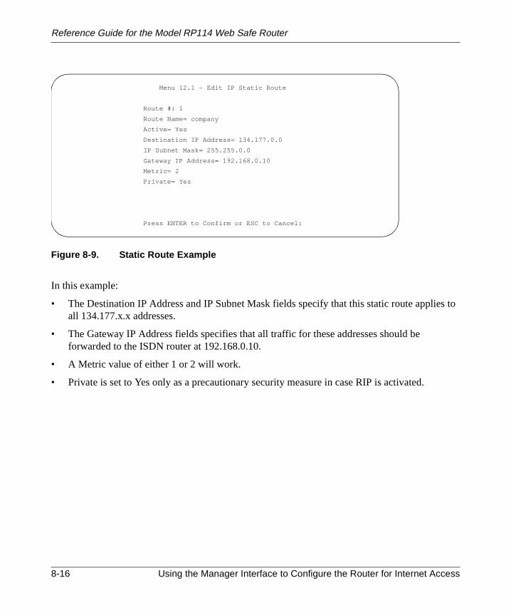
Reference Guide for the Model RP114 Web Safe Router
s to
Figure 8-9. Static Route Example
In this example:
• The Destination IP Address and IP Subnet Mask fields specify that this static route applieall 134.177.x.x addresses.
• The Gateway IP Address fields specifies that all traffic for these addresses should beforwarded to the ISDN router at 192.168.0.10.
• A Metric value of either 1 or 2 will work.
• Private is set to Yes only as a precautionary security measure in case RIP is activated.
Menu 12.1 - Edit IP Static Route
Route #: 1
Route Name= company
Active= Yes
Destination IP Address= 134.177.0.0
IP Subnet Mask= 255.255.0.0
Gateway IP Address= 192.168.0.10
Metric= 2
Private= Yes
Press ENTER to Confirm or ESC to Cancel:
8-16 Using the Manager Interface to Configure the Router for Internet Access

Reference Guide for the Model RP114 Web Safe Router
DNS
Dynamic DNS
You can configure your router to register its dynamically assigned IP address with a dynamicservice by configuring Menu 1.1, shown inFigure 8-10. To use this feature, you must have anaccount with DynDNS.org. Refer to www.dyndns.org for more information.
Figure 8-10. Menu 1.1 - Configure Dynamic DNS
Table 8-6lists and describes the fields for Menu 1.1 - Configure Dynamic DNS.
Table 8-6. Dynamic DNS Configuration Fields
Field Description
Service Provider Select your dynamic DNS service provider.
Active Use this field to activate or deactivate dynamic DNS registration.
Host Enter the static host name that will link to your dynamic IP address.
EMAIL Enter your email address for administrative contact.
USER Enter the user name of your dynamic DNS service account.
Password Enter the password of your dynamic DNS service account.
Enable Wildcard DynDNS.org allows the use of wildcards in resolving your URL. Enabling thewildcard feature for your host will cause *.yourhost.dyndns.org to bealiased to the same IP address as yourhost.dyndns.org .
Menu 1.1 - Configure Dynamic DNS
Service Provider= WWW.DynDNS.ORG
Active= No
Host=
EMAIL=
USER=
Password= ********
Enable Wildcard= No
Press ENTER to Confirm or ESC to Cancel:
Using the Manager Interface to Configure the Router for Internet Access 8-17

Reference Guide for the Model RP114 Web Safe Router
8-18 Using the Manager Interface to Configure the Router for Internet Access

toolsto the
of thember
Chapter 9Using the Manager Interface for Advanced System
Maintenance
The Model RP114 Web Safe Router provides tools for maintenance and diagnostics. Theseinclude displays of system status and connections, log and trace capabilities, and upgradessystem software. This chapter describes the use of these tools.
System Status
The System Maintenance Status Menu (Menu 24.1) allows the user to monitor the operationrouter. This screen displays the current status of the LAN and WAN Ethernet ports and the nuof packets sent and received. The system software version is also displayed.
To access the System Maintenance Status Menu:
1. Enter 24 from the Main Menu to display the System Maintenance menu (Figure 9-1).
Using the Manager Interface for Advanced System Maintenance 9-1

Reference Guide for the Model RP114 Web Safe Router
Figure 9-1. Menu 24 - System Maintenance
2. Enter 1 to display Menu 24.1 - System Maintenance - Status menu (Figure 9-2).
Figure 9-2. Menu 24.1 - System Maintenance - Status
Menu 24 - System Maintenance
1. System Status
2. System Information and Console Port Speed
3. Log and Trace
4. Diagnostic
5. Backup Configuration
6. Restore Configuration
7. Firmware Update
8. Command Interpreter Mode
9. Call Control
10. Time and Date Setting
Enter Menu Selection Number:
Menu 24.1 - System Maintenance - Status
Port Status TxPkts RxPkts Cols Tx B/s Rx B/s Up Time
WAN 10M 0 0 0 0 0 0:23:17
LAN 100M/Full 0 0 0 0 0 0:26:05
Port Ethernet Address IP Address IP Mask DHCP
WAN 00:a0:c5:e0:a0:a5 1.2.3.4 255.255.255.0 Client
LAN 00:a0:c5:e0:a0:a4 192.168.0.1 255.255.255.0 Server
System up Time: 0:26:05
Name: myRP114
Routing: IP
RAS F/W Version: V3.24(CD.0)b4 | 2/19/2001
Press Command:
COMMANDS: 1-Drop WAN 9-Reset Counters ESC-Exit
9-2 Using the Manager Interface for Advanced System Maintenance

Reference Guide for the Model RP114 Web Safe Router
nly
Table 9-1lists the commands used in the System Maintenance - Status menu.
Table 9-2lists the fields for Menu 24.1 - System Maintenance Status. These fields are read-ofields.
Table 9-1. System Maintenance Status
Command Field Name Description
Enter 1 Drop WAN Log out of PPPoE or RoadRunner session.
Enter 9 Reset counters Resets the counters.
[Esc] Exits the screen.
Table 9-2. System Maintenance Status Fields
Field Description
Statistics The statistics for the WAN and LAN ports. For each port, the screen displays:
Status The link status of the port.
TxPkts The number of packets transmitted on this port since reset or manual clear.
RxPkts The number of packets received on this port since reset or manual clear.
Cols The number of collisions on this port since reset or manual clear.
Tx B/s The current line utilization—percentage of current bandwidth used on this port.
Tx B/s The average line utilization —average CLU for this port.
Up Time The time elapsed since this port acquired link or logged in.
Addressinformation
For the WAN and LAN ports, the screen displays:
Ethernetaddress
The Ethernet MAC address of the port.
IP address The IP address assigned to the port.
IP mask The IP subnet mask assigned to the port.
DHCP The DHCP status of the port (Client, Server, or None).
System up Time The time elapsed since the last power cycle or reset.
Name The name of your router, which you configured in Menu 1 - General Setup.
RAS S/W Version The version of the current router software.
Using the Manager Interface for Advanced System Maintenance 9-3

Reference Guide for the Model RP114 Web Safe Router
may
n and
e.
croll
Log and Trace
Log and trace tools allow the user to view the error log in order to troubleshoot any errors thatoccur. The router can also generate system logs (syslogs) to send to other machines.
Enter 24 to display Menu 24 - System Maintenance. Enter 3 to select the Log and Trace optiodisplay Menu 24.3 - System Maintenance - Log and Trace.
Table 9-3lists the fields and commands for Menu 24.3 - System Maintenance - Log and Trac
View Error Log
To use the View Error Log:
1. Open Menu 24.3 - System Maintenance - Log and Trace.
2. Select the first option on Menu 24.3.
The Error log displays. The Error Log is a 64-entry circular buffer. Use the space bar to sthis screen if necessary.
3. After each display, you are prompted with an option to clear the Error Log. Enter theappropriate choice and press [Enter].
Table 9-3. System Maintenance - Log and Trace Fields
Command Field
Enter 1 View Error Log
Enter 2 Syslog and Accounting
9-4 Using the Manager Interface for Advanced System Maintenance

Reference Guide for the Model RP114 Web Safe Router
mber.
Syslog
Syslog can be configured in Menu 24.3.2 - System Maintenance - UNIX Syslog. Menu 24.3.2configures the router to send UNIX system logs to another machine.
You must configure the parameters to activate syslog (Table 9-4).
To configure the router for logging with the syslogd program on a local host:
1. Go to Menu 24.3.2 - System Maintenance - UNIX Syslog.
2. Set Active to Yes.
3. In the Syslog IP Address field, enter the IP address of the syslogd host PC.
4. Select a number for Log Facility.
You can choose any facility number, but the syslogd program must be set to the same nu
5. Select the type of activity that you would like to log.
You can enable the router to send the following types of syslog messages:
• Call detail record (CDR)
• Packet trigger
Table 9-4. System Maintenance - UNIX Syslog Fields
Field Command Description
Active Press the space bar to toggle betweenyes and no.
The syslog option is turned on or off.
Syslog IP Address Enter the address in dotted-decimalnotation such as a.b.c.d where a, b, c,and d are numbers between 0 and 255.
This field is the IP address location tosend your syslog.
Log Facility Press the space bar to toggle betweenon and off.
Seven different local options can beselected. The log facility allows themessage to be logged to different files inthe server. Refer to your UNIX manualfor more detail.
TypesCDRPacket triggeredFilter logPPP log
For each type, press the space bar totoggle between yes and no.
Enable logging for:Call detail record (CDR)Packet triggerFilter event (match or not match)PPP event
Using the Manager Interface for Advanced System Maintenance 9-5

Reference Guide for the Model RP114 Web Safe Router
enu
• Filter event log
• PPP event log
6. Save this menu.
To configure the syslogd program on the local host PC:
1. Edit the /etc/syslog.conffile to add the line:
local n.* /name_of_log_file
for example:
local6.* /var/log/rt311.log
2. In the syslogd startup script, add the -r option to enable logging from a remote host.
Diagnostic Menu
The diagnostic menu allows you to:
• Ping another location from your router.
• Release or renew DHCP parameters received from the ISP.
• Test the login to the ISP (for PPPoE only).
• Reboot the router.
From the Main Menu, enter 24 to display Menu 24 - System Maintenance. Enter 4 to display M24.4 - System Maintenance - Diagnostic, shown inFigure 9-3.
9-6 Using the Manager Interface for Advanced System Maintenance

Reference Guide for the Model RP114 Web Safe Router
enu
Figure 9-3. Menu 24.4 - System Maintenance - Diagnostic
From the Main Menu, enter 24 to display Menu 24 - System Maintenance. Enter 4 to display M24.4 - System Maintenance - Diagnostic. The available commands are listed inTable 9-5.
Table 9-5. System Maintenance - Diagnostic Fields
Field Command Description
Ping host [Enter 1] This diagnostic test pings a local or remote host. You are prompted forthe IP address of the host.
WAN DHCPRelease
[Enter 2] Release the DHCP-assigned parameters received from the ISP.
WAN DHCPRenew
[Enter 3] Issue a new DHCP request to the ISP for configuration parameters.
Intenet Setup Test [Enter 4] Attempt to login to the ISP, showing progress messages.
Reboot system [Enter 11] Your system is rebooted, implementing any changes that may havebeen recently added to your system.
Menu 24.4 - System Maintenance- Diagnostic
TCP/IP
1. Ping Host
2. WAN DHCP Release
3. WAN DHCP Renewal
4. Internet Setup Test
System
11. Reboot System
Enter Menu Selection Number:
Using the Manager Interface for Advanced System Maintenance 9-7
Reference Guide for the Model RP114 Web Safe Router
thetore
s
sing
m.
are
y
Back Up and Restore Configuration
You can save the router configuration settings to a disk as a binary file. You can also restoresettings from the file at a later time. Saving and restoring the router configuration lets you resthe router to working order if the configuration information in the router is lost or damaged.You can also use the configuration file to configure a new router of the same type if it becomenecessary to replace the router.
NETGEAR highly recommends backing up your router configuration after the router isfunctioning. You can perform the backup and restore operations through the browser or by uan FTP program. The browser procedure is described in“Configuration File Management“ onpage 6-5. The FTP procedure is described in the following section.
Backing Up and Restoring the Configuration Using FTP
To back up or restore the configuration file over the LAN, you must have an FTP client prograWindows includes an MS-DOS FTP client program that can be accessed from an MS-DOSprompt. Other FTP client programs are available through many software retailers and sharewsites.
To back up or restore the configuration:
1. If you are sending a configuration file to the router, first rename it to rom-0.
2. Establish an FTP connection to the LAN IP address of the router.
No login name is necessary. The password is the current Manager password. The factordefault password is 1234.
3. Select binary (not ascii) transfer mode.
4. Use your FTP program to get (back up) or put (restore) the file namedrom-0 in therouter.
9-8 Using the Manager Interface for Advanced System Maintenance
Reference Guide for the Model RP114 Web Safe Router
wser
owsOther
y
ory
fre
Software Update
You can update the router software through the browser or by using an FTP program. The broprocedure is described in“Software Upgrade“ on page 6-4. The FTP procedure is described in thefollowing section.
Updating Router Software Using FTP
You can update the router software over the LAN or WAN using an FTP client program. Windincludes an FTP client program that can be accessed using the Start button and Run menu.FTP client programs are available through many software retailers and shareware sites.
To update the router software:
1. Rename the new software file toras.
2. Establish an FTP connection to the router.
No login name is necessary. The password is the current Manager password. The factordefault password is 1234.
3. Select binary (not ascii) transfer mode.
4. Use your FTP program to put the file namedras in the router.
After the data transfer is finished, the router programs the upgraded firmware into flash memand reboots itself, dropping the FTP session.
Command Interpreter Mode
To enter the command interpreter mode:
• Select option 8 from Menu 24, Maintenance, to enter the command interpreter mode.
This mode allows you to diagnose, test, and configure your router using a specified set ocommands. To see a list of valid commands, type “help” at the command prompt. For modetailed information, go to the NETGEAR Web site,www.netgear.com.
• Type exit to exit the command interpreter mode.
Using the Manager Interface for Advanced System Maintenance 9-9

Reference Guide for the Model RP114 Web Safe Router
red
,
ed bypecifyrouter.
Remote Management
Although the router is normally configured by a PC on the local network, it can also be configuand managed over the Internet if remote management is enabled.
To enter the remote management menu:
• Select option 11 from Menu 24, Maintenance, to enter the Remote Management menu.
• Determine which management protocol (Telnet, FTP, or HTTP) will be enabled.
• If a non-standard port number will be used for that service, enter that port number asServer Port.
The default port (protocol) number is shown.
• Use the space bar to toggle Server Access to allow access from the LAN only, WAN onlyeither (ALL), or none (Disable).
• If you will manage the router from a particular IP address on the Internet, enter thataddress as Secured Client IP. If management will be allowed from any IP address, leaveit as 0.0.0.0.
Note: When remote management is enabled, security for the remote connection is providthe manager password and the remote manager’s IP address, if specified. If you do not san IP address, any Internet host who can guess your password will have access to your
• Press ENTER at the bottom of the menu to save your settings.
9-10 Using the Manager Interface for Advanced System Maintenance

eb
outerd on
s ofIP
acket.
dPe
ing
olve
rn ofction
Chapter 10Configuring Filters
This chapter provides information about configuring and using filters for your Model RP114 WSafe Router.
Filters are used to block certain packets, reduce traffic, and prevent security breaches. The ruses packet filters to determine whether to allow or deny passage of each data packet, baseinformation found in the packet. A filter is defined by rules declaring what information is to bechecked and what action is to be taken (forward or discard) when a match is found. Two typepacket filters are supported by the router: IP protocol filters and generic or “device” filters. Anprotocol filter screens the packet based on IP address and port information contained in the pA generic filter looks for a specified pattern of bits at a specified location in the packet.
In the configuration of IP filters, it is necessary to specify ports and protocols by their assignenumbers instead of names. A comprehensive list of protocol and port numbers for common Itraffic can be found in IETF RFC1700, “Assigned Numbers.” Many common port numbers aralso listed on any Windows PC in a file called \windows\services.
The Model RP114 router allow you to customize filter sets according to your needs. The followsections describe how to configure the filter sets for your router.
Router Filter Structure
You can configure up to 12 filter sets, each with up to six rules. For IP packets, these rules invcomparing the protocol type of a data packet (for example, TCP, UDP), source or destinationaddress, or port number. Also, a generic filter may be defined to merely test for a byte or pattebytes in a particular location in the packet. When a rule is met (or not met), a user-specified ais taken. This action may be to forward the packet, drop the packet, or go to the next rule.
Configuring Filters 10-1

Reference Guide for the Model RP114 Web Safe Router
tarules
xt to
When implementing these filter sets, you can link up to four of the filter sets to screen the dapacket. Therefore, with each filter set having up to six rules, you can have a maximum of 24active for a single filtering application.
Configuring a Filter Set
To configure a filter set:
1. Select option 21 from the Main Menu.
The Menu 21 - Filter Set Configuration (Figure 10-1) opens.
Figure 10-1. Menu 21 - Filter Set Configuration
From this menu, you can choose from 12 filter sets.
2. Select the filter that you want to configure or choose an unused set to create a new filter.
In order to distinguish between the 12 filter sets, each filter set should have a name ordescription. When you select a set for editing, you are prompted to provide descriptive tebe displayed in the comment field of Menu 21 next to the filter number.
Menu 21 - Filter Set Configuration
Filter Filter
Set # Comments Set # Comments
------ ----------------- ------ ----------------
1 NetBIOS_WAN 7 _______________
2 NetBIOS_LAN 8 _______________
3 9 _______________
4 _______________ 10 _______________
5 _______________ 11 _______________
6 _______________ 12 _______________
Enter Filter Set Number to Configure= 0
Edit Comments=
Press ENTER to Confirm or ESC to Cancel:
10-2 Configuring Filters

Reference Guide for the Model RP114 Web Safe Router
that
3. When you have finished filling in the Edit Comments field, press [Enter] at the PressENTER to Confirm... prompt to confirm your selections, or press [Esc] at any time tocancel your selections.
The new information is displayed in the read-only section of Menu 21 - Filter SetConfiguration.
4. Press [Enter] to display Menu 21.1 - Filter Rules Summary (Figure 10-2).
Figure 10-2. Menu 21.1 - Filter Rules Summary
The information in this menu is read-only; the parameters of each rule that you configured forset are displayed.
Table 10-1lists and describes the abbreviations used in Menu 21.1 - Filter Rules Summary.
Table 10-1. Abbreviations Used in Menu 21.1 - Filter Rules Summary
Abbreviation Description
# Refers to the filter rule number (1–6).
A Refers to Active. Y means the filter rule is active, and N means the filter rule isinactive.
Type Refers to the type of filter rule and can display GEN for generic or IP for TCP/IP.
Filter Rules The filter rule parameters are displayed here.
M Refers to More. Y means there are more rules to check. N means there are no rules tocheck.
Menu 21.3 - Filter Rules Summary
# A Type Filter Rules M m n
- - ---- --------------------------------------------------------------- - - -
1 Y IP Pr=6, SA=0.0.0.0, DA=0.0.0.0, DP=137 N D N
2 Y IP Pr=6, SA=0.0.0.0, DA=0.0.0.0, DP=138 N D N
3 Y IP Pr=6, SA=0.0.0.0, DA=0.0.0.0, DP=139 N D N
4 Y IP Pr=17, SA=0.0.0.0, DA=0.0.0.0, DP=137 N D N
5 Y IP Pr=17, SA=0.0.0.0, DA=0.0.0.0, DP=138 N D N
6 Y IP Pr=17, SA=0.0.0.0, DA=0.0.0.0, DP=139 N D F
Enter Filter Rule Number (1-6) to Configure:
Configuring Filters 10-3

Reference Guide for the Model RP114 Web Safe Router
For more information about filter rules, refer to“Configuring a Filter Rule,” on page 10-6.
If the filter type is IP (TCP/IP), the abbreviations listed inTable 10-2are used.
If the filter type is GEN (generic), the abbreviations listed inTable 10-3are used.
To configure a specific filter rule, select the number of the filter rule (1–6) that you want toconfigure and press [Enter] to display Menu 21.1.1 - TCP/IP Filter Rule (Figure 10-3).
m Refers to Action Matched. F means to forward the packet, D means to drop thepacket, and N means to check the next rule.
n Refers to Action Not Matched. F means to forward the packet, D means to drop thepacket, and N means to check the next rule.
Table 10-2. Abbreviations Used if Filter Type Is IP
Abbreviation Description
Pr Protocol
SA Source Address
SP Source Port number
DA Destination Address
Table 10-3. Abbreviations Used if Filter Type Is GEN
Abbreviation Description
Off Offset
Len Length
Table 10-1. Abbreviations Used in Menu 21.1 - Filter Rules Summary (continued)
Abbreviation Description
10-4 Configuring Filters

Reference Guide for the Model RP114 Web Safe Router
Figure 10-3. Menu 21.1.1 - TCP/IP Filter Rule
Menu 21.1.1 - TCP/IP Filter Rule
Filter #: 1,1
Filter Type= TCP/IP Filter Rule
Active= Yes
IP Protocol= 17 IP Source Route= No
Destination: IP Addr= 0.0.0.0
IP Mask= 0.0.0.0
Port #= 0
Port # Comp= None
Source: IP Addr= 0.0.0.0
IP Mask= 0.0.0.0
Port #= 137
Port # Comp= Equal
TCP Estab= N/A
More= No Log= None
Action Matched= Drop
Action Not Matched= Check Next Rule
Press ENTER to Confirm or ESC to Cancel:
Configuring Filters 10-5

Reference Guide for the Model RP114 Web Safe Router
ped.
er
Configuring a Filter Rule
You can configure two types of filter rules. Some of the parameters differ depending on the tyof rule. When you first enter the filter rule menu, Menu 21.1.1 - TCP/IP Filter Rule is displayeIf you want to configure another type of filter rule, select the appropriate type by pressing thespace bar under the Filter Type field and then pressing [Enter] to display the menu for the filtrule you want to enter.
TCP/IP Filter Rule
This section provides information about how to configure a TCP/IP filter rule for your router.The fields in the menu are given inTable 10-4. When you have completed Menu 21.1.1 - TCP/IPFilter Rule, press [Enter] at the Press ENTER to Confirm...prompt to confirm your selections.You can press [Esc] at any time to cancel your selections. The data you entered onMenu 21.1.1 - TCP/IP Filter Rule is displayed on Menu 21.1 - Filter Rules Summary.
Table 10-4lists and describes the TCP/IP Filter Rule menu fields.
10-6 Configuring Filters

Reference Guide for the Model RP114 Web Safe Router
Table 10-4. TCP/IP Filter Rule Fields
Field Descriptions
Active Make the filter rule active (Yes) or inactive (No).
IP Protocol Protocol refers to the IP-specific number of the protocol. The range for the valueentered in this field should be between 0 and 255 (for example, 6 refers to the TCPprotocol).
IP Source Route Yes or No in this field determines whether to check the source route.
Destination:
IP Addr Enter the destination IP address of the packet you want to filter. The address is usuallywritten in dotted-decimal notation such as a.b.c.d where a, b, c, and d are numbersbetween 0 and 255.
IP Mask Enter the IP subnet mask that will be used to mask the bits of the IP address given inDestination: IP Addr. Refer to Chapter 1, “Introduction,” for more information.
Port # Enter the destination port of the packets that you want to filter. The range of this field is0 to 65535.
Port # Comp Select the comparison quantifier you want to enable to compare to the value given inDestination: Port #. There are five options for this field:• None (default)• Less• Greater• Equal• Not Equal
Source:
IP Addr Enter the source IP address of the packet you want to filter. The IP address is usuallywritten in dotted-decimal notation such as a.b.c.d where a, b, c, and d are numbersbetween 0 and 255.
IP Mask Enter the IP subnet mask that is used to mask the bits of the IP address given inSource: IP Addr. See“Netmask” on page B-4 for information about IP subnet masks.
Port # Enter the source port of the packets that you want to filter. The range of this field is 0 to65535.
Port # Comp Select the comparison quantifier you want to use to compare to the value given inSource: Port #. There are five options for this field:• None (Default)• Less• Greater• Equal• Not Equal
Configuring Filters 10-7

Reference Guide for the Model RP114 Web Safe Router
TCP Estab This field is dependent upon the IP Protocol field. This field is inactive (N/A) unless thevalue in that field is 6 (TCP protocol). Determine what type of TCP packets to filter, fromthe following two options:• Yes—Filter match only established TCP connections• No—Filter match both initial and established TCP connections (Default)
More Determine if you want to pass the packet through the next filter rule before an action istaken. Two options are available for this field:• Yes• No (default)If More is Yes, then Action Matched and Action Not Matched is N/A.
Log Determine if you want to log the results of packets attempting to pass the filter rule.These results are displayed on the System Log (see View Error Log” on page 9-4).Seven options are available for this field:• None—No packets are logged (default).• Action Matched—Only packets that match the rule parameters are logged.• Action Not Matched—Only packets that do not match the rule parameters are logged.
Both—All packets are logged.• Check Next Rule (default)• Forward• Drop
Action MatchedAction NotMatched
If the conditions for the filter rule are not met, you can specify what to do with thepacket. There are three options for this field:• Check Next Rule (default)• Forward• Drop
Table 10-4. TCP/IP Filter Rule Fields (continued)
Field Descriptions
10-8 Configuring Filters

Reference Guide for the Model RP114 Web Safe Router
is
Generic Filter Rule
This section provides information about configuring the protocol-independent parameters fora generic filter rule for your router.Table 10-5lists the fields in the menu. When you completeMenu 21.1.1 - Generic Filter Rule, press [Enter] at the Press ENTER to Confirm... prompt toconfirm your selections. Press [Esc] at any time to cancel your selections. The data entereddisplayed on Menu 21.1 - Filter Rules Summary.
Table 10-5. Generic Filter Rule Fields
Field Description
Active Make the filter rule active (Yes) or inactive (No).
Offset Offset refers to the value of the byte that you want to use as your starting offset. That is,in the data packet, at what point do you want to begin the comparison. The range forthis field is from 0 to 255. Default = 0.
Length The length, in bytes, of the data in the packet that the router should use for comparisonand masking. The starting point of this data is determined by Offset. The range for thisfield is 0 to 8. Default = 0.
Mask Specify (in hexadecimal format) the value that the router should logically qualify and thedata in the packet. Because length is given in bytes, enter a hexadecimal number thatis twice the specified length for numbers in this field. For example, if length is 4, a validMask must have 8 hexadecimal numbers (1155ABF8).
Value Specify (in hexadecimal format ) the value that the router should use to compare withthe masked packet. The value should align with Offset. Because length is given inbytes, you need to enter twice the length in hexadecimal numbers for this field. Forexample, if length is 4, a valid value must have 8 hexadecimal numbers (1155ABF8).If the result from the masked packet matches Value, the packet is considered matched.
More Determine whether to pass the packet through the next filter rule before an action istaken. There are two options:• Yes• No (Default)If Yes is selected, Action Matched and Action Not Matched will be N/A.
Configuring Filters 10-9

Reference Guide for the Model RP114 Web Safe Router
reifyalonethe
LAN:
y Setsly set
Applying a Filter Set
After configuring a filter set in Menu 21, you must specify how the filter will be used. Filters aapplied at the LAN interface in Menu 3.1 or at the WAN interface in Menu 4.1. You must specwhether the filter is applied to incoming or outgoing packets, and whether filter sets are usedor combined. You can apply up to four filter sets to the same port by entering the numbers ofdesired filter sets separated by commas, with no spaces. In the following example, the userspecifies that filter sets 1, 3, and 10 are to be applied to packets entering the router from the
Incoming Filter Sets = 1,3,10
In cascading filter sets, you may need to modify all but the last set in order to have each setcontinue to the next set rather than terminate. In the example above, you may need to modif1 and 3 so that they continue to Set 10. On the last rule of a standalone filter set, you normal“Action if Matched” and “Action if Not Matched” to either “forward”or “drop.” However, if youcascade the filter set to another filter set, one of these actions must be “Check Next Rule.”
Log Determine if you want to log the results of packets attempting to pass the filter rule.These results are displayed on the System Log (see “View Error Log” on page 9-4).Seven options are available:• None—No packets are logged (default).• Action Matched—Only packets that match the rule parameters are logged.• Action Not Matched—Only packets that do not match the rule parameters are logged.• Both—All packets are logged.• Check Next Rule (default)• Forward• Drop
Action Matched,Action NotMatched
If the conditions for the filter rule are not met, you can specify what to do withthe packet. Three options are available:• Check Next Rule (default)• Forward• Drop
Table 10-5. Generic Filter Rule Fields (continued)
Field Description
10-10 Configuring Filters

Reference Guide for the Model RP114 Web Safe Router
e port
of 21
r set.
Default Filters
The Model RP114 router is preconfigured with the filters shown inFigure 10-1onpage 10-2andin this section.
Filter 1: NetBIOS_WAN
The NetBIOS_WAN filter is an IP protocol filter used to prevent the sending of WindowsNetBIOS name service packets to the ISP. The ports used by NetBIOS name service are:
• 137 (TCP and UDP) NetBIOS Name Service
• 138 (TCP and UDP) NetBIOS Datagram Service
• 139 (TCP and UDP) NetBIOS Session Service
This filter is applied in Menu 11.5 - Remote Node Filter as an Output Filter set.
Filter 2: NetBIOS_LAN
The NetBIOS_LAN filter is an IP protocol filter used to block NetBIOS name service requestsfrom a local PC to the DNS server of the ISP. These requests are UDP packets having a sourcof 137 (NNS) and a destination port of 53 (DNS).
This filter is applied in Menu 3.1 - LAN Port Filter as an Input Filter set.
Filter 3: TEL_FTP_WEB_WAN
The TEL_FTP_WEB_LAN filter is an IP protocol filter used to block Telnet, HTTP, and FTPrequests to the router from the Internet. The filter blocks TCP packets with a destination port(FTP), 23 (Telnet), or 80 (HTTP).
This filter is not used, but can be applied in Menu 11.5 - Remote Node Filter as an Input Filte
Configuring Filters 10-11

Reference Guide for the Model RP114 Web Safe Router
10-12 Configuring Filters

fterlem.
a
h
ould
pply
uct.
Chapter 11Troubleshooting
This chapter gives information about troubleshooting your Model RP114 Web Safe Router. Aeach problem description, instructions are provided to help you diagnose and solve the prob
Basic Functioning
After you turn on power to the router, the following sequence of events should occur:
• The PWR LED lights.
• The router performs a self-test for 30 seconds, during which the Test LED should blink atrate of about 0.5 Hz and then turn off.
• If the LAN and WAN Ethernet connections are correctly made to operational devices, eacLNK or LNK/ACT LED should be on.
• If a LAN Ethernet port is connected to a device that operates at 100 Mbps, the 100 LED shbe on.
If any of these conditions does not occur, refer to the appropriate following section.
PWR LED Not On
If the PWR and other LEDs are off when your router is turned on:
• Make sure that the power cord is properly connected to your router and that the power suadapter is properly connected to a functioning power outlet.
• Check that you are using the 12 V DC power adapter supplied by NETGEAR for this prod
If the error persists, you have a hardware problem and should contact technical support.
Troubleshooting 11-1

Reference Guide for the Model RP114 Web Safe Router
atelyere
f
rt.
n
wash
ious
.0.2 to
Test LED Never Blinks or LED Stays On
When the router is turned on, the Test LED blinks for about 30 seconds at a rate of approxim0.5 Hz and then turns off. If the Test LED does not blink, or if it stops blinking and stays on, this a fault within the router.
If you experience problems with the Test LED:
• Cycle the power to see if the router recovers and the LED blinks for the correct amount otime.
If the error persists, you might have a hardware problem and should contact technical suppo
LNK/ACT LEDs Not On
If either the LAN LNK/ACT LED or WAN LNK LED does not light when the Ethernet connectiois made, check the following:
• Make sure that the Ethernet cable connections are secure at the router and at the hub orworkstation.
• Make sure that power is turned on to the connected hub or workstation.
• Be sure you are using the correct cable:
— When connecting the router’s WAN port to a cable or DSL modem, use the cable thatsupplied with the cable or DSL modem. This cable may be a standard straight-througEthernet cable or an Ethernet crossover cable.
Troubleshooting the Web Configuration Interface
If you are unable to access the router’s Web Configuration interface from a PC on your localnetwork, check the following:
• Check the Ethernet connection between your PC and the router as described in the prevsection.
• Make sure your PC’s IP address is on the same subnet as the router. If you are using therecommended addressing scheme, your PC’s address should be in the range of 192.168192.168.0.32. Refer to“Verifying TCP/IP Properties (Windows)“ on page 3-4or “VerifyingTCP/IP Properties (Macintosh)“ on page 3-6to find your PC’s IP address. Follow theinstructions inChapter 3to configure your PC.
11-2 Troubleshooting

Reference Guide for the Model RP114 Web Safe Router
thee ofC to
et
is
clear
k the
, but
ables, your
Note: Recent versions of Windows and MacOS will generate and assign an IP address ifcomputer cannot reach a DHCP server. These auto-generated addresses are in the rang169.254.x.x. If your IP address is in this range, check the Ethernet connection from the Pthe router and reboot your PC.
• Make sure your browser has Java, JavaScript, or ActiveX enabled. If you are using InternExplorer, click Refresh to be sure the Java applet is loaded.
• Make sure you are using the correct login information. The factory default login name is“admin” and the password is “1234”. Make sure that CAPS LOCK is off when entering thinformation.
• Try quitting the browser and launching it again.
• If your router’s IP address has been changed and you don’t know the current IP address,the router’s configuration to factory defaults. This will set the router’s IP address to192.168.0.1.
If the router does not save changes you have made in the Web Configuration Interface, checfollowing:
• When entering configuration settings, be sure to click the APPLY button before moving toanother menu or tab, or your changes are lost.
• Click the Refresh or Reload button in the Web browser. The changes may have occurredthe Web browser may be caching the old configuration.
Troubleshooting the ISP Connection
If your router is unable to access the Internet, you should first determine whether the router isto obtain a WAN IP address from the ISP. Unless you have been assigned a static IP addresrouter must request an IP address from the ISP. You can determine whether the request wassuccessful using either the browser interface or the Manager interface.
To check the WAN IP address from the browser interface:
1. Launch your browser and select an external site such as www.netgear.com
2. Access the Main Menu of the router’s configuration at http://192.168.0.1
3. Under the Advanced heading, click on Maintenance
4. Check that an IP address is shown for the WAN Port
If 0.0.0.0 is shown, your router has not obtained an IP address from your ISP.
Troubleshooting 11-3

Reference Guide for the Model RP114 Web Safe Router
le or
r to
he
r
’s
ter’s
u 2,
To check the WAN IP address from the Manager interface:
1. If your system uses a login script such as PPPoE or RoadRunner, go to Managerinterface Menu 24.4 - System Maintenance - Diagnostic and select Internet Setup Test.
This will cause your router to attempt to login to the ISP.
2. Go to Manager interface Menu 24.1 - System Maintenance - Status
3. Check that an IP address is shown for the WAN Port
If 0.0.0.0 is shown, your router has not obtained an IP address from your ISP.
If your router is unable to obtain an IP address from the ISP, you may need to force your cabDSL modem to recognize your new router by performing the following procedure:
1. Turn off power to the cable or DSL modem.
2. Turn off power to your router.
3. Wait five minutes and reapply power to the cable or DSL modem.
4. When the modem’s LEDs indicate that it has reacquired sync with the ISP, reapply poweyour router.
If your router is still unable to obtain an IP address from the ISP, the problem may be one of tfollowing:
• Your ISP may require a login program.
Ask your ISP whether they require PPP over Ethernet (PPPoE) or a RoadRunner login.
• If you have selected a login program, you may have incorrectly set the login name andpassword.
• Your ISP may check for your PC's host name.
Assign the PC Host Name of your ISP account to the router as System Name in ManageMenu 1, or as Host Name in the browser-based Setup Wizard.
• Your ISP only allows one MAC address to connect to Internet, and may check for your PCMAC address.
Inform your ISP that you have bought a new network device, and ask them to use the rouMAC address.
OR
Configure your router to spoof your PC’s MAC address. This can be done in Manager Menor in the browser-based Setup Wizard.
11-4 Troubleshooting

Reference Guide for the Model RP114 Web Safe Router
e
esses)
ot
acketCP/IP.4)
ctly.
If your router can obtain an IP address, but your PC is unable to load any web pages from thInternet:
• Your PC may not recognize any DNS server addresses.
A DNS server is a host on the Internet that translates Internet names (such as www addrto numeric IP addresses. Typically your ISP will provide the addresses of one or two DNSservers for your use. If you entered a DNS address during the router’s configuration, reboyour PC and verify the DNS address as described in“Verifying TCP/IP Properties (Windows)“on page 3-4. Alternatively, you may configure your PC manually with DNS addresses, asexplained in your operating system documentation.
• Your PC may not have the router configured as its TCP/IP gateway.
If your PC obtains its information from the router by DHCP, reboot the PC and verify thegateway address as described in“Verifying TCP/IP Properties (Windows)“ on page 3-4.
Troubleshooting a TCP/IP Network Using a Ping Utility
Most TCP/IP terminal devices and routers contain a ping utility that sends an echo request pto the designated device. The device then responds with an echo reply. Troubleshooting a Tnetwork is made very easy by using the ping utility in the built-in Manager interface (Menu 24or in your PC or workstation.
Testing the LAN Path to Your Router
You can ping the router from your PC to verify that the LAN path to your router is set up corre
To ping the router from a PC running Windows 95 or later:
1. From the Windows toolbar, click on the Start button and select Run.
2. In the field provided, type Ping followed by the IP address of the router, as in thisexample:
ping 192.168.0.1
3. Click on OK.
You should see a message like this one:
Pinging <IP address> with 32 bytes of data
If the path is working, you see this message:
Reply from < IP address >: bytes=32 time=NN ms TTL=xxx
Troubleshooting 11-5

Reference Guide for the Model RP114 Web Safe Router
nd
d
t the
If the path is not working, you see this message:
Request timed out
If the path is not functioning correctly, you could have one of the following problems:
• Wrong physical connections
— Make sure the LAN LNK/ACT LED is on. If the LNK/ACT LED is off, follow theinstructions in“LNK/ACT LEDs Not On” on page 11-2.
— Check that the corresponding Link LEDs are on for your network interface card afor the hub ports (if any) that are connected to your workstation and router.
• Wrong network configuration
— Verify that the Ethernet card driver software and TCP/IP software are both installeand configured on your PC or workstation.
— Verify that the IP address for your router and your workstation are correct and thaaddresses are on the same subnet.
11-6 Troubleshooting

Reference Guide for the Model RP114 Web Safe Router
ce:
do
he IPe
ss
ified
eing.
e in
ost
f a
r
lnet
Testing the Path from Your PC to a Remote Device
After verifying that the LAN path works correctly, test the path from your PC to a remote devi
• From the Windows run menu, type PING -n 10 followed by the IP address of a remotedevice such as your ISP’s DNS server.
If the path is functioning correctly, replies as in the previous section are displayed. If younot receive replies:
— Check that your PC has the IP address of your router listed as the default gateway. If tconfiguration of your PC is assigned by DHCP, this information will not be visible in thcontrol panel network utility. Go to the Run… window and run winipcfg. The IP addreof the router should appear as the Default Gateway.
— Check to see that the network address of your PC (the portion of the IP address specby the netmask) is different from the network address of the remote device.
— Check internal Manager Menu 24.1 to verify the WAN status. If the menu indicates thWAN status as down, check that your cable or DSL modem is connected and function
— Check the error log in Menu 24.3.1 for any indication of problems.
— If your ISP assigned a host name to your PC, enter that host name as the router namMenu 1.
— Your ISP could be rejecting the Ethernet MAC addresses of all but one of your PCs. Mbroadband ISPs restrict access by only allowing traffic from the MAC address of yourbroadband modem, but some ISPs additionally restrict access to the MAC address osingle PC connected to that modem. If this is the case, you must configure Menu 2 toallow the router to “borrow” or “spoof” the MAC address from the authorized PC. Refeto “WAN Setup” on page 7-7.
Troubleshooting the Manager Interface
If you cannot access the Manager interface by using the Telnet Protocol:
• Verify the Ethernet connection between your PC and the router. Refer to“Testing the LANPath to Your Router,” on page 11-5.
• If you are attempting to telnet from the WAN side, you must disable the factory default Tefilter that prevents Telnet access from the WAN. Refer toChapter 10, “Configuring Filters,”for information about setting and clearing filters.
Troubleshooting 11-7

Reference Guide for the Model RP114 Web Safe Router
clear
hen
or IP
s.
• If your router’s IP address has been changed and you don’t know the current IP address,the router’s configuration to factory defaults. This will set the router’s IP address to192.168.0.1.
Restoring the Default Configuration and Password
This section explains how to restore the factory default configuration settings, changing theManager password to 1234 and the IP address to 192.168.0.1. You can erase the currentconfiguration and restore factory defaults in several ways:
• Use the Erase function of the Web Manager (see“Erase the Configuration“ on page 6-5).
• Upload the default config fileromfile0.114, which can be found on theModel RP114 ResourceCD. This config file is also available on the NETGEAR Web site. The config file can beuploaded through the Web Manager (see“Configuration File Management“ on page 6-5), orby ftp (see“Backing Up and Restoring the Configuration Using FTP“ on page 9-8).
• Use the Default Reset button on the rear panel of the router. Use this method for cases wthe Manager password or IP address is not known.
Using the Default Reset button
To restore the factory default configuration settings without knowing the Manager passwordaddress, you must use the Default Reset button on the rear panel of the router.
1. Press the Default Reset button for 10 seconds, then release it.
If the TEST LED begins to blink, the defaults have been restored and the router is nowrebooting. Otherwise, go to step 2.
2. Disconnect the power from the router.
3. While depressing the Default Reset button, reconnect power to the router.
The TEST LED will begin to blink, then will flicker very quickly after about 10 or 15 secondThis indicates that the defaults have been restored and the router is now rebooting.
4. Release the Default Reset button and wait for the router to reboot.
11-8 Troubleshooting

Appendix ATechnical Specifications
This appendix provides technical specifications for the Model RP114 Web Safe Router.
General Specifications
Network Protocol and Standards Compatibility
Data and Routing Protocols: TCP/IP, RIP-1, RIP-2, DHCPPPP over Ethernet (PPPoE)
Power Adapter
North America: 120V, 60 Hz, input
United Kingdom, Australia: 240V, 50 Hz, input
Europe: 230V, 50 Hz, input
Japan: 100V, 50/60 Hz, input
All regions (output): 12 V DC @ 1.2A output, 30W maximum
Technical Specifications A-1

Reference Guide for the Model RP114 Web Safe Router
Physical Specifications
Dimensions: 159 by 102 by 32 mm6.25 by 4 by 1.3 in.
Weight: 2.75 kg1.25 lb.
Environmental Specifications
Operating temperature: 0° to 40° C
Operating humidity: 90% maximum relative humidity, noncondensing
Electromagnetic Emissions
Meets requirements of: FCC Part 15 Class B
VCCI Class B
EN 55 022 (CISPR 22), Class B
Interface Specifications
LAN: 10BASE-T or 100BASE-Tx, RJ-45
WAN: 10BASE-T, RJ-45
A-2 Technical Specifications

eacan-speedf the
afficuter.
n ins up atersrk
Appendix BNetwork and Routing Basics
This chapter provides an overview of IP networks and routing.
Basic Router Concepts
Large amounts of bandwidth can be provided easily and relatively inexpensively in a local arnetwork (LAN). However, providing high bandwidth between a local network and the Internetbe very expensive. Because of this expense, Internet access is usually provided by a slowerwide-area network (WAN) link such as a cable or DSL modem. In order to make the best use oslower WAN link, a mechanism must be in place for selecting and transmitting only the data trmeant for the Internet. The function of selecting and forwarding this data is performed by a ro
What is a Router?
A router is a device that forwards traffic between networks based on network layer informatiothe data and on routing tables maintained by the router. In these routing tables, a router buildlogical picture of the overall network by gathering and exchanging information with other rouin the network. Using this information, the router chooses the best path for forwarding netwotraffic.
Network and Routing Basics B-1

Reference Guide for the Model RP114 Web Safe Router
uting
ngost
t mustocks of).from
ot
ss. The
Routers vary in performance and scale, number of routing protocols supported, and types ofphysical WAN connection they support. The Model RP114 Web Safe Router is a small officerouter that routes the IP protocol over a single-user broadband connection.
Routing Information Protocol
One of the protocols used by a router to build and maintain a picture of the network is the RoInformation Protocol (RIP). Using RIP, routers periodically update one another and check forchanges to add to the routing table.
The Model RP114 router supports both the older RIP-1 and the newer RIP-2 protocols. Amoother improvements, RIP-2 supports subnet and multicast protocols. RIP is not required for mhome applications.
IP Addresses and the Internet
Because TCP/IP networks are interconnected across the world, every machine on the Internehave a unique address to make sure that transmitted data reaches the correct destination. Bladdresses are assigned to organizations by the Internet Assigned Numbers Authority (IANAIndividual users and small organizations may obtain their addresses either from the IANA oran Internet service provider (ISP). You can contact IANA at www.iana.org.
The Internet Protocol (IP) uses a 32-bit address structure. The address is usually written in dnotation (also called dotted-decimal notation), in which each group of eight bits is written indecimal form, separated by decimal points.
For example, the following binary address:
11000011 00100010 00001100 00000111
is normally written as:
195.34.12.7
The latter version is easier to remember and easier to enter into your computer.
In addition, the 32 bits of the address are subdivided into two parts. The first part of the addreidentifies the network, and the second part identifies the host node or station on the networkdividing point may vary depending on the address range and the application.
B-2 Network and Routing Basics

Reference Guide for the Model RP114 Web Safe Router
ofostsIPware
ght-bit
16-bit
the
There are five standard classes of IP addresses. These address classes have different waysdetermining the network and host sections of the address, allowing for different numbers of hon a network. Each address type begins with a unique bit pattern, which is used by the TCP/software to identify the address class. After the address class has been determined, the softcan correctly identify the host section of the address. The follow figure shows the three mainaddress classes, including network and host sections of the address for each address type.
Figure B-1. Three Main Address Classes
The five address classes are:
• Class AClass A addresses can have up to 16,777,214 hosts on a single network. They use an einetwork number and a 24-bit node number. Class A addresses are in this range:
1.x.x.x to 126.x.x.x.
• Class BClass B addresses can have up to 65,354 hosts on a network. A Class B address uses anetwork number and a 16-bit node number. Class B addresses are in this range:
128.1.x.x to 191.254.x.x.
• Class CClass C addresses can have 254 hosts on a network. Class C addresses use 24 bits fornetwork address and eight bits for the node. They are in this range:
192.0.1.x to 223.255.254.x.
7261
Class A
Network Node
Class B
Class C
Network Node
Network Node
Network and Routing Basics B-3

Reference Guide for the Model RP114 Web Safe Router
sses are
each
hostAlso,adcast
ss andtmask
usings for
s thehere,
rms ofwardating
• Class DClass D addresses are used for multicasts (messages sent to many hosts). Class D addrein this range:
224.0.0.0 to 239.255.255.255.
• Class EClass E addresses are for experimental use.
This addressing structure allows IP addresses to uniquely identify each physical network andnode on each physical network.
For each unique value of the network portion of the address, the base address of the range (address of all zeros) is known as the network address and is not usually assigned to a host.the top address of the range (host address of all ones) is not assigned, but is used as the broaddress for simultaneously sending a packet to all hosts with the same network address.
Netmask
In each of the address classes previously described, the size of the two parts (network addrehost address) is implied by the class. This partitioning scheme can also be expressed by a neassociated with the IP address. A netmask is a 32-bit quantity that, when logically combined (an AND operator) with an IP address, yields the network address. For instance, the netmaskClass A, B, and C addresses are 255.0.0.0, 255.255.0.0, and 255.255.255.0, respectively.
For example, the address 192.168.170.237 is a Class C IP address whose network portion iupper 24 bits. When combined (using an AND operator) with the Class C netmask, as shownonly the network portion of the address remains:
11000000 10101000 10101010 11101101 (192.168.170.237)
combined with:
11111111 11111111 11111111 00000000 (255.255.255.0)
Equals:
11000000 10101000 10101010 00000000 (192.168.170.0)
As a shorter alternative to dotted-decimal notation, the netmask may also be expressed in tethe number of ones from the left. This number is appended to the IP address, following a backslash ( / ), as “/n.” In the example, the address could be written as 192.168.170.237/24, indicthat the netmask is 24 ones followed by 8 zeros.
B-4 Network and Routing Basics

Reference Guide for the Model RP114 Web Safe Router
are aend ofuldt
nstead.
t
e, theingeted asngssing
t
u areonlyss Crkrks
Subnet Addressing
By looking at the addressing structures, you can see that even with a Class C address, therelarge number of hosts per network. Such a structure is an inefficient use of addresses if eacha routed link requires a different network number. It is unlikely that the smaller office LANs wohave that many devices. You can resolve this problem by using a technique known as subneaddressing.
Subnet addressing allows us to split one IP network address into smaller multiple physicalnetworks known as subnetworks. Some of the node numbers are used as a subnet number iA Class B address gives us 16 bits of node numbers translating to 64,000 nodes. Mostorganizations do not use 64,000 nodes, so there are free bits that can be reassigned. Subneaddressing makes use of those bits that are free, as shown below.
Figure B-2. Example of Subnetting a Class B Address
A Class B address can be effectively translated into multiple Class C addresses. For examplIP address of 172.16.0.0 is assigned, but node addresses are limited to 255 maximum, alloweight extra bits to use as a subnet address. The IP address of 172.16.97.235 would be interprIP network address 172.16, subnet number 97, and node number 235. In addition to extendithe number of addresses available, subnet addressing provides other benefits. Subnet addreallows a network manager to construct an address scheme for the network by using differensubnets for other geographical locations in the network or for other departments in theorganization.
Although the preceding example uses the entire third octet for a subnet address, note that yonot restricted to octet boundaries in subnetting. To create more network numbers, you needshift some bits from the host address to the network address. For instance, to partition a Clanetwork number (192.68.135.0) into two, you shift one bit from the host address to the netwoaddress. The new netmask (or subnet mask) is 255.255.255.128. The first subnet has netwonumber 192.68.135.0 with hosts 192.68.135.1 to 129.68.135.126, and the second subnet hanetwork number 192.68.135.128 with hosts 192.68.135.129 to 192.68.135.254.
7262
Class B
Network Subnet Node
Network and Routing Basics B-5

Reference Guide for the Model RP114 Web Safe Router
ecimalt0.
the
esswork
The following table lists the additional subnet mask bits in dotted-decimal notation. To use thtable, write down the original class netmask and replace the 0 value octets with the dotted-devalue of the additional subnet bits. For example, to partition your Class C network with subnemask 255.255.255.0 into 16 subnets (4 bits), the new subnet mask becomes 255.255.255.24
The following table displays several common netmask values in both the dotted-decimal andmasklength formats.
Note: The number 192.68.135.127 is not assigned because it is the broadcast addrof the first subnet. The number 192.68.135.128 is not assigned because it is the netaddress of the second subnet.
Table B-1. Netmask Notation Translation Table for One Octet
Number of Bits Dotted-Decimal Value
1 128
2 192
3 224
4 240
5 248
6 252
7 254
8 255
Table B-2. Netmask Formats
Dotted-Decimal Masklength
255.0.0.0 /8
255.255.0.0 /16
255.255.255.0 /24
255.255.255.128 /25
255.255.255.192 /26
255.255.255.224 /27
255.255.255.240 /28
255.255.255.248 /29
B-6 Network and Routing Basics

Reference Guide for the Model RP114 Web Safe Router
ame
localvices
te
igning
he97,
t
NETGEAR strongly recommends that you configure all hosts on a LAN segment to use the snetmask for the following reasons:
• So that hosts recognize local IP broadcast packets
When a device broadcasts to its segment neighbors, it uses a destination address of thenetwork address with all ones for the host address. In order for this scheme to work, all deon the segment must agree on which bits comprise the host address.
• So that a local router or bridge recognizes which addresses are local and which are remo
Private IP Addresses
If your local network is isolated from the Internet (for example, when using NAT), you can assany IP addresses to the hosts without problems. However, the IANA has reserved the followthree blocks of IP addresses specifically for private networks:
10.0.0.0 - 10.255.255.255172.16.0.0 - 172.31.255.255192.168.0.0 - 192.168.255.255
NETGEAR recommends that you choose your private network number from this range. TheDHCP server of the Model RP114 router is preconfigured to automatically assign privateaddresses.
Regardless of your particular situation, do not create an arbitrary IP address; always follow tguidelines explained here. For more information about address assignment, refer to RFC 15Address Allocation for Private Internets,and RFC 1466,Guidelines for Management of IPAddress Space. The Internet Engineering Task Force (IETF) publishes RFCs on its Web site awww.ietf.org.
255.255.255.252 /30
255.255.255.254 /31
255.255.255.255 /32
Table B-2. Netmask Formats
Network and Routing Basics B-7

Reference Guide for the Model RP114 Web Safe Router
toaeningle
aeithern, refer
Single IP Address Operation Using NAT
In the past, if multiple PCs on a LAN needed to access the Internet simultaneously, you hadobtain a range of IP addresses from the ISP. This type of Internet account is more costly thansingle-address account typically used by a single user with a modem, rather than a router. ThModel RP114 router employs an address-sharing method called Network Address Translatio(NAT). This method allows several networked PCs to share an Internet account using only a sIP address, which may be statically or dynamically assigned by your ISP.
The router accomplishes this address sharing by translating the internal LAN IP addresses tosingle address that is globally unique on the Internet. The internal LAN IP addresses can beprivate addresses or registered addresses. For more information about IP address translatioto RFC 1631,The IP Network Address Translator (NAT).
The following figure illustrates a single IP address operation.
Figure B-3. Single IP Address Operation Using NAT
7786EA
192.168.0.2
192.168.0.3
192.168.0.4
192.168.0.5
192.168.0.1 172.21.15.105
Private IP addressesassigned by user
Internet
IP addressesassigned by ISP
B-8 Network and Routing Basics

Reference Guide for the Model RP114 Web Safe Router
on
data
ess,
ocol
ot yettworkpart of
her
dingACle. The.
seJust ass to
ain thelargee the
This scheme offers the additional benefit of firewall-like protection because the internal LANaddresses are not available to the Internet through the translated connection. All incominginquiries are filtered out by the router. This filtering can prevent intruders from probing yoursystem. However, using port forwarding, you can allow one PC (for example, a Web server)your local network to be accessible to outside users.
MAC Addresses and Address Resolution Protocol
An IP address alone cannot be used to deliver data from one LAN device to another. To sendbetween LAN devices, you must convert the IP address of the destination device to its mediaaccess control (MAC) address. Each device on an Ethernet network has a unique MAC addrwhich is a 48-bit number assigned to each device by the manufacturer. The technique thatassociates the IP address with a MAC address is known as address resolution. Internet Protuses the Address Resolution Protocol (ARP) to resolve MAC addresses.
If a device sends data to another station on the network and the destination MAC address is nrecorded, ARP is used. An ARP request is broadcast onto the network. All stations on the nereceive and read the request. The destination IP address for the chosen station is included asthe message so that only the station with this IP address responds to the ARP request. All otstations discard the request.
The station with the correct IP address responds with its own MAC address directly to the sendevice. The receiving station provides the transmitting station with the required destination Maddress. The IP address data and MAC address data for each station are held in an ARP tabnext time data is sent, the address can be obtained from the address information in the table
Domain Name Server
Many of the resources on the Internet can be addressed by simple descriptive names such awww.NETGEAR.com. This addressing is very helpful at the application level, but the descriptivname must be translated to an IP address in order for a user to actually contact the resource.a telephone directory maps names to phone numbers, or as an ARP table maps IP addresseMAC addresses, a domain name system (DNS) server maps descriptive names of networkresources to IP addresses.
When a PC accesses a resource by its descriptive name, it first contacts a DNS server to obtIP address of the resource. The PC sends the desired message using the IP address. Manyorganizations, such as ISPs, maintain their own DNS servers and allow their customers to usservers to look up addresses.
Network and Routing Basics B-9

Reference Guide for the Model RP114 Web Safe Router
dress.s andod by
icePDNSas the
uteraddress
ntlyed inTP
IP Configuration by DHCP
When an IP-based local area network is installed, each PC must be configured with an IP adIf the PCs need to access the Internet, they should also be configured with a gateway addresone or more DNS server addresses. As an alternative to manual configuration, there is a methwhich each PC on the network can automatically obtain this configuration information. A devon the network may act as a Dynamic Host Configuration Protocol (DHCP) server. The DHCserver stores a list or pool of IP addresses, along with other information (such as gateway andaddresses) that it may assign to the other devices on the network. The Model RP114 router hcapacity to act as a DHCP server.
The Model RP114 router also functions as a DHCP client when connecting to the ISP. The rocan automatically obtain an IP address, subnet mask, DNS server addresses, and a gatewayif the ISP provides this information by DHCP.
Ethernet Cabling
Although Ethernet networks originally used thick or thin coaxial cable, most installations curreuse unshielded twisted pair (UTP) cabling. The UTP cable contains eight conductors, arrangfour twisted pairs, and terminated with an RJ45 type connector. A normal "straight-through" UEthernet cable follows the EIA568B standard wiring and pinout as described inTable B-3.
Table B-3. UTP Ethernet cable wiring, straight-through
Pin Wire color Signal
1 Orange/White Transmit (Tx) +
2 Orange Transmit (Tx) -
3 Green/White Receive (Rx) +
4 Blue
5 Blue/White
6 Green Receive (Rx) -
7 Brown/White
8 Brown
B-10 Network and Routing Basics

Reference Guide for the Model RP114 Web Safe Router
PC,andisC, oris
hat
d atst beit is
er
olarity
low, or
Uplink Switches, Crossover Cables, and MDI/MDIX Switching
In the wiring table above, the concept of transmit and receive are from the perspective of thewhich is wired as Media Dependant Interface (MDI). In this wiring, the PC transmits on pins 12. At the hub, the perspective is reversed, and the hub receives on pins 1 and 2. This wiringreferred to as Media Dependant Interface - Crossover (MDI-X). When connecting a PC to a Pa hub port to another hub port, the transmit pair must be exchanged with the receive pair. Thexchange is done by one of three mechanisms:
• Uplink switchMost hubs provide an Uplink switch which will exchange the pairs on one port, allowing tport to be connected to another hub using a normal Ethernet cable.
• Crossover cableA crossover cable is a special cable in which the transmit and receive pairs are exchangeone of the two cable connectors. Crossover cables are often unmarked as such, and muidentified by comparing the two connectors. Since the cable connectors are clear plastic,easy to place them side by side and view the order of the wire colors on each. On astraight-through cable, the color order will be the same on both connectors. On a crossovcable, the orange and blue pairs will be exchanged from one connector to the other.
• Auto MDI/MDI-X switchingSome Ethernet switch products, such as the Model RP114 router, are able to sense the pof a connection and automatically adapt to the proper mating polarity.
Cable Quality
A twisted pair Ethernet network operating at 10 Mbits/second (10BASE-T) will often toleratequality cables, but at 100 Mbits/second (10BASE-Tx) the cable must be rated as Category 5"Cat 5", by the Electronic Industry Association (EIA). This rating will be printed on the cablejacket. A Category 5 cable will meet specified requirements regarding loss and crosstalk. Inaddition, there are restrictions on maximum cable length for both 10 and 100 Mbits/secondnetworks.
Network and Routing Basics B-11

Reference Guide for the Model RP114 Web Safe Router
B-12 Network and Routing Basics

.
e
Glossary
10BASE-T IEEE 802.3 specification for 10 Mbps Ethernet over twisted pair wiring.
100BASE-Tx IEEE 802.3 specification for 100 Mbps Ethernet over twisted pair wiring.
CAT5 Category 5. An Electronic Industry Association (EIA) rating for twisted paircable that meets specified loss and crosstalk requirements for high-speednetworking. The cable rating is printed on the cable jacket.
DHCP SeeDynamic Host Configuration Protocol.
DNS SeeDomain Name Server.
Domain Name Server A Domain Name Server (DNS) resolves descriptive names of networkresources (such as www.netgear.com) to numeric IP addresses.
Dynamic HostConfigurationProtocol
An Ethernet protocol that provides a centralized administration point forassigning network configuration information.
IP SeeInternet Protocol.
IP Address A 4-byte number uniquely defining each host on the Internet. Ranges ofaddresses are assigned by Internic, an organization formed for this purposeUsually written in dotted-decimal notation with periods separating the bytes(for example, 134.177.244.57).
IPSec Internet Protocol Security. IPSec is a series of guidelines for securing privatinformation transmitted over public networks. IPSec is a VPN methodproviding a higher level of security than PPTP.
IPX SeeInternet Packet Exchange.
ISP Internet service provider.
Internet PacketExchange
Novell’s internetworking protocol.
Glossary 1

Reference Guide for the Model RP114 Web Safe Router
,d
to
ae
s
the
Internet Protocol The main internetworking protocol used in the Internet. Used in conjunctionwith the Transfer Control Protocol (TCP) to form TCP/IP.
LAN Seelocal area network.
local area network A communications network serving users within a limited geographical areasuch as one floor of a building, controlled by a network operating system anusing a transport protocol.
MAC address Media Access Control address. A unique 48-bit hardware address assignedevery Ethernet node. Usually written in the form 01:23:45:67:89:ab.
MSB SeeMost Significant Bit or Most Significant Byte.
MRU SeeMaximum Receive Unit.
Maximum ReceiveUnit
The size in bytes of the largest packet that can be sent or received.
Most Significant Bit orMost Significant Byte
The portion of a number, address, or field that is farthest left when written assingle number in conventional hexadecimal ordinary notation. The part of thnumber having the most value.
NAT SeeNetwork Address Translation.
netmask A number that explains which part of an IP address comprises the networkaddress and which part is the host address on that network. It can beexpressed in dotted-decimal notation or as a number appended to the IPaddress. For example, a 28-bit mask starting from the MSB can be shown a255.255.255.192 or as /28 appended to the IP address.
Network AddressTranslation
A technique by which several hosts share a single IP address for access toInternet.
PPP SeePoint-to-Point Protocol.
PPP over Ethernet(PPPoE)
PPP over Ethernet is a protocol for connecting remote hosts to the Internetover an always-on connection by simulating a dial-up connection.
PPTP Point-to-Point Tunneling Protocol. A method for establishing a virtual privatenetwork (VPN) by embedding Microsoft’s network protocol into Internetpackets.
PSTN Public Switched Telephone Network.
packet A block of information sent over a network. A packet typically contains asource and destination network address, some protocol and lengthinformation, a block of data, and a checksum.
2 Glossary

Reference Guide for the Model RP114 Web Safe Router
es
es
o
tte
Point-to-PointProtocol
PPP. A protocol allowing a computer using TCP/IP to connect directly to theInternet.
RFC Request For Comment. Refers to documents published by the InternetEngineering Task Force (IETF) proposing standard protocols and procedurfor the Internet. RFCs can be found at www.ietf.org.
RIP SeeRouting Information Protocol.
router A device that forwards data between networks. An IP router forwards databased on IP source and destination addresses.
Routing InformationProtocol
A protocol in which routers periodically exchange information with oneanother so that they can determine minimum distance paths between sourcand destinations.
subnet mask Seenetmask.
UTP Unshielded twisted pair. The cable used by 10BASE-T and 100BASE-TxEthernet networks.
VPN Virtual Private Network. A method for securely transporting data between twprivate networks by using a public network such as the Internet as aconnection.
WAN Seewide area network.
wide area network A long distance link used to extend or connect remotely located local areanetworks.
Windows InternetNaming Service
WINS. Windows Internet Naming Service is a server process for resolvingWindows-based computer names to IP addresses. If a remote networkcontains a WINS server, your Windows PCs can gather information from thaWINS server about its local hosts. This allows your PCs to browse that remonetwork using Network Neighborhood.
WINS SeeWindows Internet Naming Service.
Glossary 3

Reference Guide for the Model RP114 Web Safe Router
4 Glossary

0
Index
AAction Matched/Not Matched field
Generic Filter Rule menu 10-10TCP/IP Filter Rule menu 10-8
Active fieldEdit IP Static Route menu 5-9, 8-14Generic Filter Rule menu 10-9Remote Node Profile menu 8-4Syslog and Accounting menu 9-5TCP/IP Filter Rule menu 10-7
Address Resolution Protocol B-9
Alcatel ANT 4-4, 8-5
auto MDI/MDI-X switching B-11
Auto Uplink 1-4
Bbackup configuration 6-5
Bigpond 4-5
BigPond Authentication 3-7
blockingby keyword 4-9
Ccables, pinout B-10
Cabling B-10
Cat5 cable 2-2, 2-4, B-11
command interpreter mode 9-9
configurationautomatic by DHCP 1-4backup 6-5, 9-8erasing 6-5restore 6-5router, initial 4-1
Connection ID/Name 4-5, 8-5
content filtering 1-3
conventionstypography xvii
crossover cable 1-4, 2-5, 11-2, B-11
customer support iii
Ddaylight savings time 4-9
default reset button 11-8
default router address 7-1
Destination field, TCP/IP Filter Rule menu 10-7
Destination IP Address field, Edit IP Static Routemenu 5-9, 8-14
DHCP 1-4, 5-3, B-10
DHCP Client ID 3-6
DHCP Setup field, Ethernet Setup menu 5-4, 6-2, 7-1
DMZ 1-3, 5-7, 8-10
DNS Proxy 1-4, 5-4, 7-10
DNS server 3-9, 4-6, B-9
DNS, dynamic 5-2
domain 3-9
Domain Name 4-3
domain name server (DNS).SeeDNS server
Dynamic DNS 5-2, 8-17
dynamic NAT.SeeNetwork Address Translation
EEdit IP Static Route menu 8-14
Encapsulation 4-4, 8-2, 8-5
End Port 5-7
erase configuration 6-5
error log 9-4
Index 1

Ethernet cable B-10
Ethernet field, System Maintenance menu 9-3
Ffactory settings, restoring 6-5
features 1-1
Filter Rules Summary menu 10-3, 10-9
filter type, Generic IP 10-4
filters, configuring 10-1
Flash memory, for firmware upgrade 1-3
front panel 2-3
FTP 9-8
FTP, updating the router software 9-9
Ggateway address 3-9
Gateway IP Address field, Edit IP Static Route menu5-9, 8-14
General Setup menu 7-6
Generic Filter Rule menu 10-9
Hhost name 4-3, 7-6
IIANA
contacting B-2
IETF xvWeb site address B-7
IGMP 5-5, 7-11, 8-7
Input and Output Filters field, Ethernet Setup menu7-9
installation 1-5
Internet accountaddress information 3-8establishing 3-7
Internet, accessing 8-1
IP addresses 3-8, 3-9
and NAT B-8and the Internet B-2assigning xv, B-2auto-generated 11-3masquerading 1-4private B-7translating xvi
IP configuration by DHCP B-10
IP networkingfor Macintosh 3-5for Windows 3-2
IP Protocol field, TCP/IP Filter Rule menu 10-7
IP Source Route field, TCP/IP Filter Rule menu 10-7
IP Subnet Mask field, Edit IP Static Route menu 5-9,8-14
Kkeyword blocking 4-9
LLAN Setup Menu 5-3
LEDsdescription 2-3troubleshooting 11-2
Length field, Generic Filter Rule menu 10-9
log 9-4sending 4-8
Log and Trace menu 9-4
log entries 4-12
Log Facility field, Syslog and Accounting menu 9-5
Log fieldGeneric Filter Rule menu 10-10TCP/IP Filter Rule menu 10-8
MMAC Address 7-7, 11-7, B-9
MAC addressspoofing 4-6, 11-4
Macintosh 3-8configuring for IP networking 3-5DHCP Client ID 3-6
2 Index

Obtaining ISP Configuration Information 3-9
Manager interfacecommands 7-4menus 7-4troubleshooting 11-7using for configuring 1-2
Manager interface menusDiagnostic 9-6, 9-7Edit IP Static Route 8-14Filter Rules Summary 10-3, 10-9General Setup Menu 7-6Generic Filter Rule 10-9Internet Access Setup 8-1LAN Setup Menu 7-8Log and Trace 9-4Main 7-3Remote Node Network Layer Options 8-7Remote Node Setup 8-3Syslog and Accounting 9-5System Security 7-11System Status 9-1TCP/IP Filter Rule 10-6WAN Setup 7-7WAN Setup Menu 7-7
Mask field, Generic Filter Rule menu 10-9
MDI/MDI-X wiring B-11
Metric fieldEdit IP Static Route menu 5-10, 8-15Remote Node Network Layer Options menu 8-7
mode, command interpreter 9-9
More fieldGeneric Filter Rule menu 10-9TCP/IP Filter Rule menu 10-8
Multicast 5-5, 7-11
NName field, System Maintenance menu 9-3
NAT. SeeNetwork Address Translation
NetBIOS Name Service 10-11
NETGEARcontacting xv
netmasktranslation table B-6
Network Address Translation 1-4, B-8
Network Time Protocol 4-9
newsgroup 4-10
NNTP newsgroup 4-10
NTP 4-9
OOffset field, Generic Filter Rule menu 10-9
Outgoing field, Remote Node Profile menu 8-5
Ppackage contents 2-1
passwordchanging 7-11restoring 11-8
PC, using to configure 3-10
pinout, Ethernet cable B-10
Port Forwarding 5-6
port forwarding behind NAT B-9
Port Forwarding Menu 5-6
PPPoptions, editing 8-6
PPP over Ethernet 1-2, 1-4, 3-7, 8-2
PPPoE 1-2, 1-4, 3-7, 4-4, 8-2, 8-5
PPTP 3-7
PPTP, login for Europe 4-4, 8-5
Primary DNS Server 4-6
Private fieldEdit IP Static Route menu 5-10, 8-15Remote Node Network Layer Options menu 8-7
protocolsAddress Resolution B-9DHCP 1-4, B-10Routing Information 1-4, B-2support 1-2
publications, related xv
Rrange, port forwarding 5-7
Index 3

RAS S/W Version, System Maintenance menu 9-3
rear panel 2-4
Rem Node Name field, Remote Node Profile menu8-4
Rem Subnet Mask field, Remote Node Network LayerOptions 8-7
Remote Management 9-10
remote nodesetup 8-3
Remote Node Network Layer Options menu 8-7
Remote Note Set Up menu 8-3
requirementsaccess device 2-2hardware 2-2
reset button, clearing config 11-8
restore configuration 6-5
restore factory settings 6-5
RFC1466 xv, B-71597 xv, B-71631 xvi, B-8finding B-7
RoadRunner 3-7, 4-5, 8-3
rom-0 file 6-5
romfile0.114 11-8
Route Name field, Edit IP Static Route menu 5-9, 8-14
router concepts B-1
Routing Information Protocol 1-4, B-2
SSecondary DNS Server 4-6
security 1-1, 1-3, 7-11
Service Name 4-4, 8-5
Service Type 8-5
Session Options fieldRemote Node Profile menu 8-5
Setup Wizard 4-1
Single User Account field, Remote Node NetworkLayer Options menu 8-7
single user account, configuring for 8-10
SMTP 4-8
software, updating 9-9
Source field, TCP/IP Filter Rule menu 10-7
spoof MAC address 11-4
Start Port 5-7
static route setup 8-12
subnet addressing B-5
subnet mask 3-8, 3-9, B-5
Syslog and Accounting menu 9-5
Syslog IP Address field, Syslog and Accounting menu9-5
syslogd 9-5
System Maintenance menu 9-1, 9-3
TTCP Estab field, TCP/IP Filter Rule menu 10-8
TCP/IPconfiguring 3-1network, troubleshooting 11-5
TCP/IP Filter Rule menu 10-6
TCP/IP propertiesverifying for Macintosh 3-6verifying for Windows 3-4
TCP/IP Setup field, Ethernet Setup menu 5-4, 7-10
technical support xv
Telnet access 10-11
Telstra 4-5
time zone 4-9
time-stamping 4-9
trace tools 9-4
troubleshooting 11-1
Trusted Host 4-11
typographical conventions xvii
Uuplink switch B-11
4 Index

VValue field, Generic Filter Rule menu 10-9
version 1-1
Wwarranty 1-3, 1-5
Windows, configuring for IP routing 3-2
winipcfg utility 3-4
World Wide Web iii
Index 5