manual for rs232 and parallel links q - marking.com.uamarking.com.ua/instrukcii/manual...
TRANSCRIPT
M a n u a l f o r R S 2 3 2 a n d p a r a l l e l l i n k s
S m a l l c h a r a c t e r i n k - j e t p r i n t i n g
For information

For information
Contents
A36981-A.doc3/138
General 7
■ Introduction 9
■ Description of signals used 10 Reference (GND) 10 DSR (Data Set Ready) voltage level transmission 10 DTR (Data Terminal Ready) voltage level transmission 10 TXD (Transmit Data) voltage level transmission 10 RXD (Receive Data) voltage level transmission 10
■ Electrical specifications 11
■ Timing diagram 11
■ General principle of dialog 12 Data sent from computer to printer 12 Data requested by computer from printer 12 Identifier (1 hexadecimal byte) 13 Length (2 hexadecimal bytes) 13 Data 13 Check byte (Checksum) 13 Reminder 14
■ Hardware configuration 15 Presentation of the industrial interface board terminal block 15 Terminal block B1: Communication 15 Industrial interface board 16 Jumper positions 17 Recommended connection diagram 18
■ Programming the printer 19
Lists of identifiers 23
■ General list of V24 commands 25
■ List of transmissions to printer 26
■ List of requests to printer 27
For information
Contents
A36981-A.doc4/138
Transmissions to printer 29
■ Transmissions regarding the printer 31 Printer shutdown / start-up 31 Reset faults 32 Transmit keyboard code 33 Transmit security code 34 Permit menu modification by keyboard if DSR active 35 Transmit print acknowledgement request 36 Transmit printer initialization 41 Upload files to Master, IP65, and Contrast 43
■ Transmission concerning heads 47 Transmit jet condition/maintenance 47
■ Transmissions concerning messages 48 Transmit message number to print 48 Transmit non-library message (complete, parameters or text) 49 Transmit library message (complete, parameters or text) 50 Transmit partial message 51 Transmit external variables 53
■ Transmissions regarding variable items (counter, time code, autodating) 54 Transmit current counter value 54 Reset counters 55 Transmit tables of months and time codes 56 Initialize autodating 57 Transmit autodating table 58
Requests to the printer 59
■ Requests regarding the printer 61 V24 dialog request 61 Request keyboard code 62 Request printer parameters 63 Request condition of ink circuit solenoid valves, fluid levels, measured viscosity, reference viscosity and number of additive additions. 64 Request CRCs of printer PROMs 66 Request printer faults 68
For information
Contents
A36981-A.doc5/138
Status request for Contrast Printers 72
■ Requests concerning heads 75 Request jet status 75 Request jet speed and phase 76
■ Requests concerning messages 77 Request complete current message 77 Command printing 78
■ Requests regarding variable items 79 Request current counters 79 Request PPP printing counter 80 Request autodating 81 Request for an autodating table 82 Request tables of months and time codes 84
Details of data 85
■ Details of message data 87 Structure indicator 87 General message parameters 88 Variable item parameters 89 Definition of lines 94 Definition of blocks 95 List of standard fonts 96 Detail of text 97 End of message 104
Programming examples and performance 105
■ Synoptic - General principle of a V24 exchange 107
■ Programming – Transmission of complete message 110
■ Programming – Transmission of partial message 114
■ Performance 115
For information
Contents
A36981-A.doc6/138
■ Results 116
1. Direct mode 116
2. Standard mode 117
Parallel link - Presentation 119
■ Introduction 121
■ Parallel link characteristics 122 Signals transmitted on the parallel link 122 Specifications for levels transmitted 122
■ Connection diagrams 123
Parallel link - Message selection 127
■ Selecting a message from the library 129 BCD code for message number 129 Hexadecimal code for message number 130 Reverse message direction option 130
■ Diagram of input signals 131
■ General parallel link operation 132
■ Restriction on parallel interface operation 132
■ Use depending on printer configurations 133 1.1 (one single-jet head) and 1.2 (one twin-jet head) printers 133 2.1 (two single-jet heads) and 2.2 (two twin-jet heads) printers 133
■ Manual updates 135
For information

A36981-A.doc7/138
General
For information

General
A36981-A.doc8/138
For information
General
A36981-A.doc9/138
■ Introduction This manual concerns 9040, 9040 IP65, 9040 Contrast and 9040 S printers which have an asynchronous, half duplex serial interface connected to a computer in V24 voltage level mode. The RS232C (or V24) standard describes the signals available during dialog between a DTE (Data Terminal Equipment) and a DCE (Data Communication Equipment). No more than 7 signals are used to connect to a printer.
NOTE The printer should be considered as a DTE.
IMPORTANT Avoid making any modifications using the printer keyboard during a V24 dialog (risk of conflict). It is also recommended that 9040, 9040 IP65, 9040 Contrast and 9040 S printers be left in "main menu" mode during V24 dialog.
For information
General
A36981-A.doc10/138
■ Description of signals used
Reference (GND)
Common ground between computer and printer.
DSR (Data Set Ready) voltage level transmission
This is an input to the printer. This signal enables the printer's V24 mode.
A symbol is displayed on the printer display when the DSR signal is active. ( in lower left corner of display window).
DTR (Data Terminal Ready) voltage level transmission
This is an output from the printer. This signal is active as soon as the printer is ready to dialog.
TXD (Transmit Data) voltage level transmission
This is an output from the printer. Data transmitted.
RXD (Receive Data) voltage level transmission
This is an input to the printer. Data received. For information
General
A36981-A.doc11/138
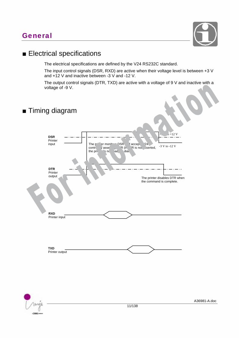
■ Electrical specifications The electrical specifications are defined by the V24 RS232C standard. The input control signals (DSR, RXD) are active when their voltage level is between +3 V and +12 V and inactive between -3 V and -12 V. The output control signals (DTR, TXD) are active with a voltage of 9 V and inactive with a voltage of -9 V.
■ Timing diagram
The printer monitors DSR and accepts V24 control by asserting DTR (if DTR is not asserted, the printer is not ready to dialog).
The printer disables DTR when the command is complete.
-3 V to -12 V
+3 V to +12 V DSR Printer input
DTR Printer output
RXD Printer input
TXD Printer output
For information
General
A36981-A.doc12/138
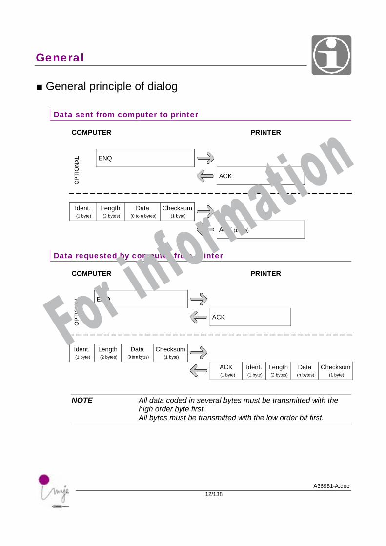
■ General principle of dialog
Data sent from computer to printer
COMPUTER PRINTER
ENQ
OP
TIO
NAL
ACK
Ident. (1 byte)
Length (2 bytes)
Data (0 to n bytes)
Checksum(1 byte)
ACK (1 byte)
Data requested by computer from printer
COMPUTER PRINTER
ENQ
OPT
ION
AL
ACK
Ident. (1 byte)
Length (2 bytes)
Data (0 to n bytes)
Checksum(1 byte)
ACK (1 byte)
Ident. (1 byte)
Length (2 bytes)
Data (n bytes)
Checksum(1 byte)
NOTE All data coded in several bytes must be transmitted with the high order byte first. All bytes must be transmitted with the low order bit first.
For information
General
A36981-A.doc13/138
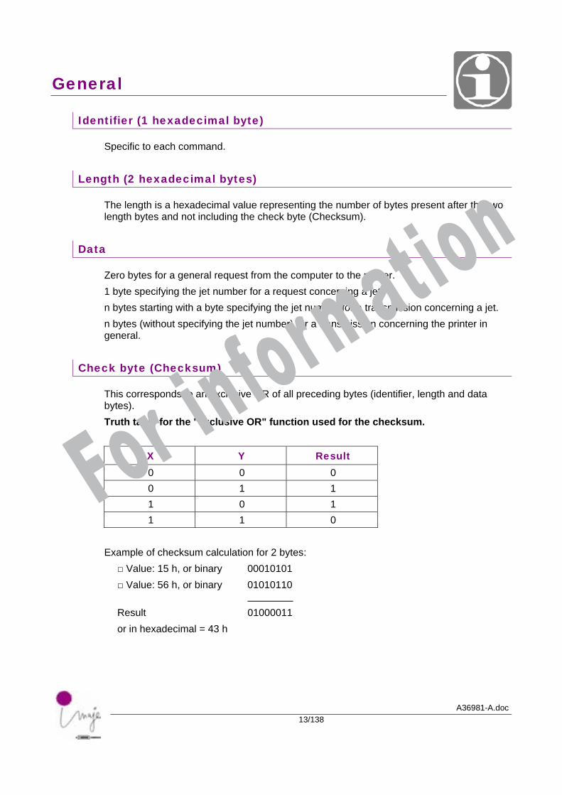
Identifier (1 hexadecimal byte)
Specific to each command.
Length (2 hexadecimal bytes)
The length is a hexadecimal value representing the number of bytes present after the two length bytes and not including the check byte (Checksum).
Data
Zero bytes for a general request from the computer to the printer. 1 byte specifying the jet number for a request concerning a jet. n bytes starting with a byte specifying the jet number for a transmission concerning a jet. n bytes (without specifying the jet number) for a transmission concerning the printer in general.
Check byte (Checksum)
This corresponds to an exclusive OR of all preceding bytes (identifier, length and data bytes). Truth table for the "exclusive OR" function used for the checksum.
X Y Result 0 0 0 0 1 1 1 0 1 1 1 0
Example of checksum calculation for 2 bytes:
□ Value: 15 h, or binary 00010101 □ Value: 56 h, or binary 01010110 Result 01000011 or in hexadecimal = 43 h
For information
General
A36981-A.doc14/138
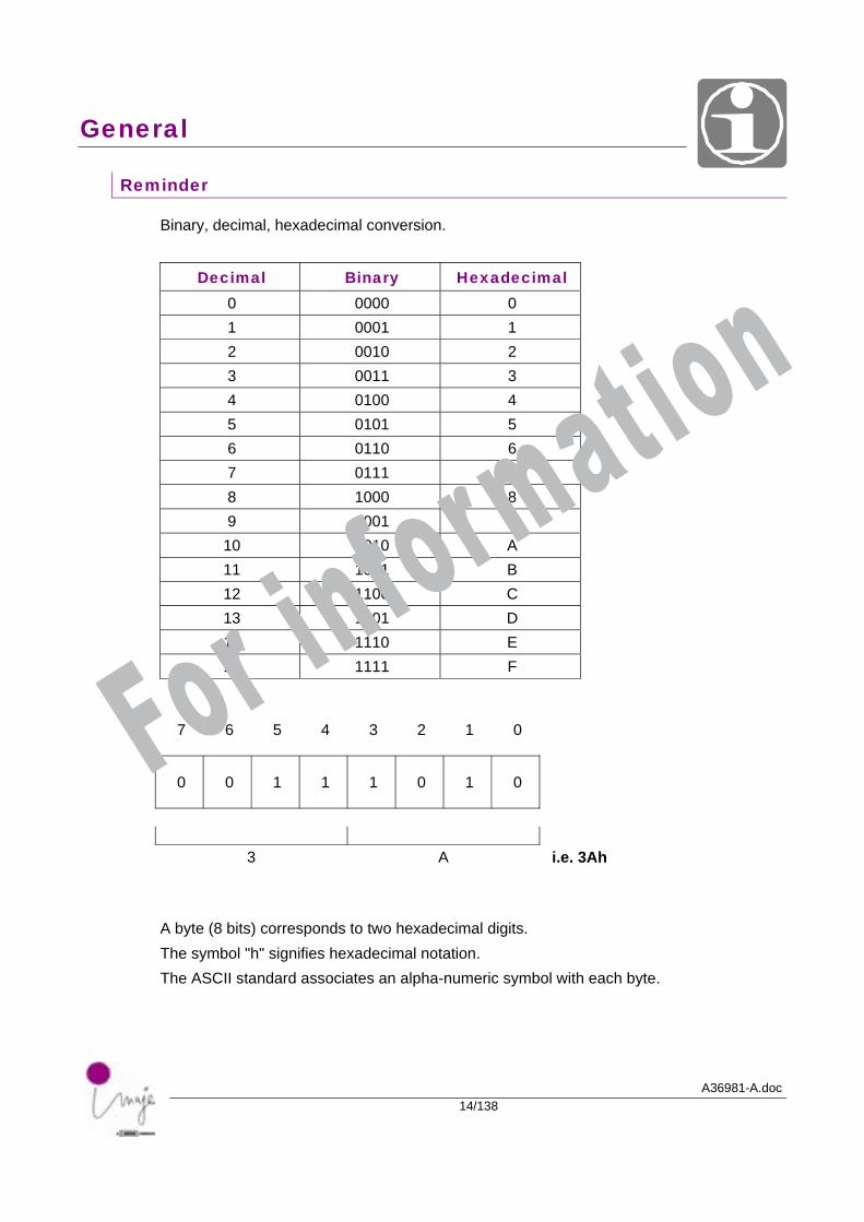
Reminder
Binary, decimal, hexadecimal conversion.
Decimal Binary Hexadecimal 0 0000 0 1 0001 1 2 0010 2 3 0011 3 4 0100 4 5 0101 5 6 0110 6 7 0111 7 8 1000 8 9 1001 9 10 1010 A 11 1011 B 12 1100 C 13 1101 D 14 1110 E 15 1111 F
7 6 5 4 3 2 1 0
0 0 1 1 1 0 1 0
3 A i.e. 3Ah
A byte (8 bits) corresponds to two hexadecimal digits. The symbol "h" signifies hexadecimal notation. The ASCII standard associates an alpha-numeric symbol with each byte.
For information
General
A36981-A.doc15/138
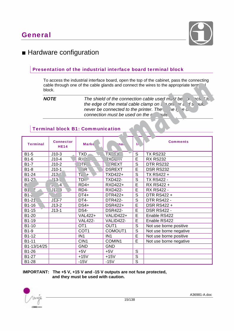
■ Hardware configuration
Presentation of the industrial interface board terminal block
To access the industrial interface board, open the top of the cabinet, pass the connecting cable through one of the cable glands and connect the wires to the appropriate terminal block.
NOTE The shield of the connection cable used must be connected to the edge of the metal cable clamp on the printer and should never be connected to the printer. The same type of connection must be used on the computer.
Terminal block B1: Communication
Terminal Connector
HE14 Marked Signal I/O
Comments
B1-5 J10-3 TXD TXDEXT S TX RS232 B1-6 J10-4 RXD RXDEXT E RX RS232 B1-7 J10-2 DTR DTREXT S DTR RS232 B1-8 J10-1 DSR DSREXT E DSR RS232 B1-24 J13-10 TD4+ TXD422+ S TX RS422 + B1-23 J13-9 TD4- TXD422- S TX RS422 - B1-18 J13-4 RD4+ RXD422+ E RX RS422 + B1-17 J13-3 RD4- RXD422- E RX RS422 - B1-22 J13-8 DT4+ DTR422+ S DTR RS422 + B1-21 J13-7 DT4- DTR422- S DTR RS422 - B1-16 J13-2 DS4+ DSR422+ E DSR RS422 + B1-15 J13-1 DS4- DSR422- E DSR RS422 - B1-20 VAL422+ VALID422+ E Enable RS422 B1-19 VAL422- VALID422- E Enable RS422 B1-10 OT1 OUT1 S Not use borne positive B1-9 COT1 COMOUT1 S Not use borne negative B1-12 IN1 IN1 E Not use borne positive B1-11 CIN1 COMIN1 E Not use borne negative B1-13/14/25 GND GND B1-26 +5V +5V S B1-27 +15V +15V S B1-28 -15V -15V S
IMPORTANT: The +5 V, +15 V and -15 V outputs are not fuse protected, and they must be used with caution.
For information
General
A36981-A.doc16/138
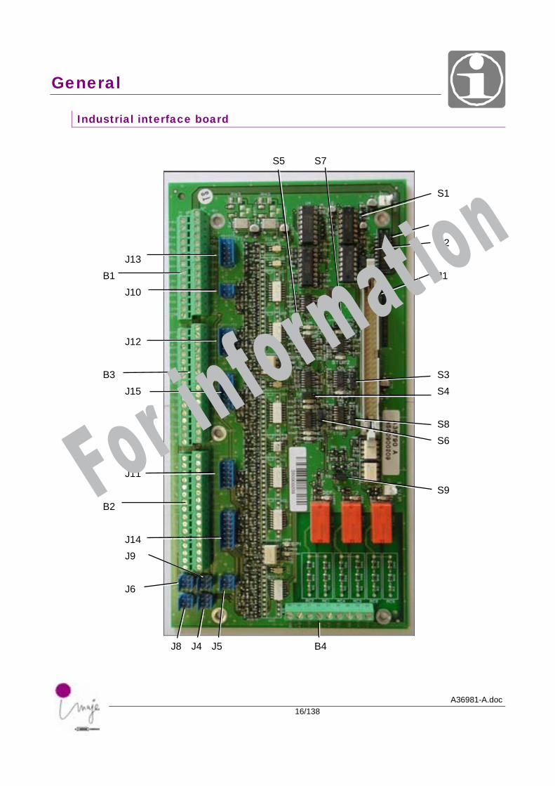
Industrial interface board
S5 S7 S1 J7 S2 J13 B1 J1 J10 J12 B3 S3 J15 S4 S8 S6 J11 S9 B2 J14 J9 J6
J8 J4 J5 B4
For information
General
A36981-A.doc17/138
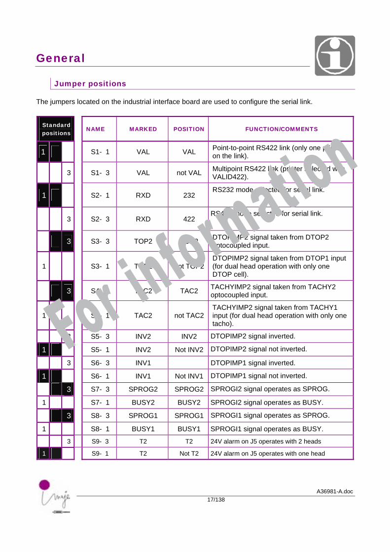
Jumper positions
The jumpers located on the industrial interface board are used to configure the serial link.
Standard positions
NAME MARKED POSITION FUNCTION/COMMENTS
1 S1- 1 VAL VAL Point-to-point RS422 link (only one printer on the link).
3 S1- 3 VAL not VAL Multipoint RS422 link (printer selected with VALID422).
1 S2- 1 RXD 232 RS232 mode selected for serial link.
3 S2- 3 RXD 422 RS422 mode selected for serial link.
3 S3- 3 TOP2 TOP2 DTOPIMP2 signal taken from DTOP2 optocoupled input.
1 S3- 1 TOP2 not TOP2DTOPIMP2 signal taken from DTOP1 input (for dual head operation with only one DTOP cell).
3 S4- 3 TAC2 TAC2 TACHYIMP2 signal taken from TACHY2 optocoupled input.
1 S4- 1 TAC2 not TAC2 TACHYIMP2 signal taken from TACHY1 input (for dual head operation with only one tacho).
3 S5- 3 INV2 INV2 DTOPIMP2 signal inverted.
1 S5- 1 INV2 Not INV2 DTOPIMP2 signal not inverted.
3 S6- 3 INV1 DTOPIMP1 signal inverted.
1 S6- 1 INV1 Not INV1 DTOPIMP1 signal not inverted.
3 S7- 3 SPROG2 SPROG2 SPROGI2 signal operates as SPROG.
1 S7- 1 BUSY2 BUSY2 SPROGI2 signal operates as BUSY.
3 S8- 3 SPROG1 SPROG1 SPROGI1 signal operates as SPROG.
1
S8- 1 BUSY1 BUSY1 SPROGI1 signal operates as BUSY.
3 S9- 3 T2 T2 24V alarm on J5 operates with 2 heads
1 S9- 1 T2 Not T2 24V alarm on J5 operates with one head
For information
General
A36981-A.doc18/138
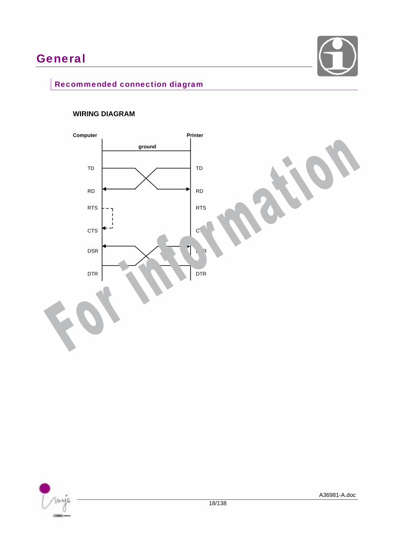
Recommended connection diagram
WIRING DIAGRAM Computer Printer
ground
TD TD RD RD
RTS RTS CTS CTS DSR DSR DTR DTR
For information
General
A36981-A.doc19/138
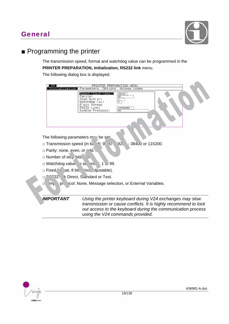
■ Programming the printer The transmission speed, format and watchdog value can be programmed in the PRINTER PREPARATION, Initialization, RS232 link menu. The following dialog box is displayed.
The following parameters may be set: □ Transmission speed (in baud): 9600 - 19200 - 38400 or 115200. □ Parity: none, even, or odd. □ Number of stop bits 1 or 2. □ Watchdog value (in seconds): 1 to 99. □ Fixed format, 8 bits: (not adjustable). □ RS232 link Direct, Standard or Test. □ Simple protocol: None, Message selection, or External Variables.
IMPORTANT Using the printer keyboard during V24 exchanges may slow transmission or cause conflicts. It is highly recommend to lock out access to the keyboard during the communication process using the V24 commands provided.
For information
General
A36981-A.doc20/138
■ RS232 link
□ Direct: The operator interface sends V24 commands to the CPU without processing them. This is the quickest mode of operation. In the PRODUCTION menu: . The current message is not displayed. . Message names are replaced by asterisks (*). . The PC interface is not updated.
Any menu open is automatically closed when a message is received.
□ Standard:
The operator interface takes into account V24 commands on their way to the CPU. The processing time is at least 80 ms. In the PRODUCTION menu: . Pressing 1 or 2 displays the current message on head 1 or 2. . The message name varies to match the current message.
□ Test:
This mode of operation is not recommended for applications where the message changes regularly. Processing time to display message (3 to 10 s). In the PRODUCTION menu: . All messages sent or selected by V24 are automatically displayed. . The message name also changes to match the external selection. For information
General
A36981-A.doc21/138
■ Simple protocol
□ None: Only the conventional protocol is used for external communication (identifier - length - data - check byte).
□ Message selection: In addition to the conventional protocol, the name of a message may be transmitted in a simplified protocol to select it for printing. Format: STX (02h) / Message name (maximum 8 characters) / ETX (03h). . This command only addresses head 1 of the printer. . It should preferably be used without a library. . Messages may be selected from all those stored in the interface.
□ External variables: In addition to the conventional protocol, the contents of external variables may be transmitted in a simplified protocol to update the message printed. Format: STX (02h) / Variable1, Variable 2, … (in ASCII) / ETX (03h). . This command only addresses head 1 of the printer. . The number of characters sent must be equal to the total number of characters reserved in all external fields in the message. . Variable values are sent in turn, in the order of their respective fields in the message to be printed, from jet 1 to jet n. . If an external variable is declared in a barcode with plain text transcription, the frame value must be sent together with the plain text value. In this case the variable is sent twice, at the reserved locations. Example: STX (02h) / Variable 1, Variable 1 / ETX (03h).
CAUTION: APPLIES TO EXTERNAL VARIABLES
he update affects all jets for the current message, on head 1 only. The message must be selected manually on the operator interface, not by external communication.The maximum size of variables is 1022 characters. No checks are made on variable values. Users must ensure that the content is consistent with the fields reserved in the message to be printed.If the list of variables is incomplete or empty, it is completed with spaces.If the list is too long it is truncated.
For information

A36981-A.doc22/138
For information

A36981-A.doc23/138
Lists of identifiers
For information

Lists of identifiers
A36981-A.doc24/138
For information
Lists of identifiers
A36981-A.doc25/138
■ General list of V24 commands
Identifier Description of command
05h V24 dialog request 0Fh Permit menu modification by keyboard if DSR active 20h Request printer parameters 30h Printer shutdown / start-up 31h Transmit jet status / Maintenance 32h Request jet status / Maintenance 33h Request jet speed and phase 35h Request IC solenoid valve, Fluid levels and viscosity meter condition 36h Transmit printer initialization 37h Request CRCs of printer PROMs 39h Request current counters 3Ah Reset counters 3Bh Request printer faults 3Ch Reset faults 3Eh Transmit keyboard code 3Fh Transmit security code 41h Transmit print acknowledgement request 43h Request complete current message 45h Request keyboard code 4Dh Request status for Contrast 50h Upload files to Master, IP65, Contrast 51h Transmit current counter value 52h Request tables of months and time codes 53h Transmit tables of months and time codes 56h Request PPP printing counter 57h Transmit non-library message (complete, parameters or text) 58h Transmit library message (complete, parameters or text) 59h Transmit partial message 5Ah Transmit message number to print 5Bh Transmit external variables 94h Manual printing / Order printing C8h Initialize autodating D6h Request autodating DEh Request for an autodating table DFh Transmit autodating table
For information
Lists of identifiers
A36981-A.doc26/138
■ List of transmissions to printer
Description of command Identifier
PRINTER
Printer shutdown / start-up 30h Reset faults 3Ch Transmit keyboard code 3Eh Transmit security code 3Fh Permit menu modification by keyboard if DSR active 0Fh Transmit print acknowledgement request 41h Transmit printer initialization 36h Upload files to Master, IP65, Contrast 50h
HEAD
Transmit jet status / Maintenance 31h
MESSAGE
Transmit message number to print 5Ah Transmit external variables 5Bh Transmit non-library message (complete, parameters or text) 57h Transmit library message (complete, parameters or text) 58h Transmit partial message 59h
VARIABLES
Transmit current counter value 51h Reset counters 3Ah Transmit tables of months and time codes 53h Initialize autodating C8h Transmit autodating table DFh
For information
Lists of identifiers
A36981-A.doc27/138
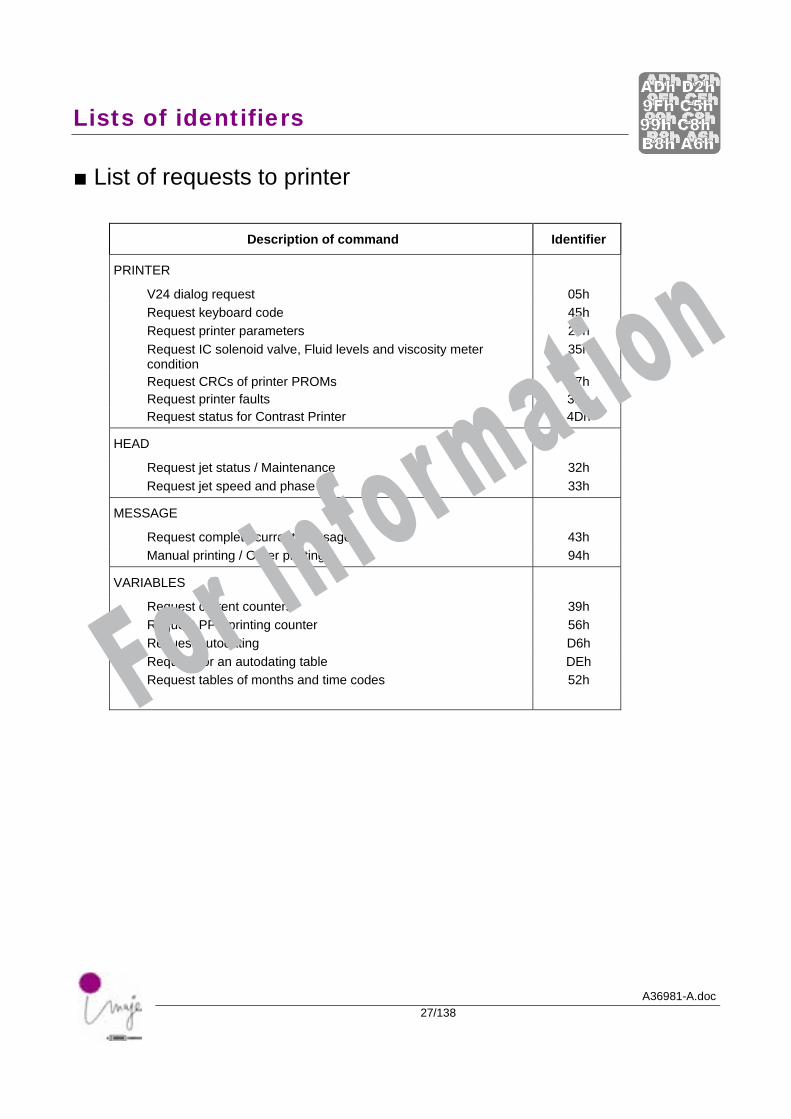
■ List of requests to printer
Description of command Identifier
PRINTER
V24 dialog request 05h Request keyboard code 45h Request printer parameters 20h Request IC solenoid valve, Fluid levels and viscosity meter condition
35h
Request CRCs of printer PROMs Request printer faults
37h 3Bh
Request status for Contrast Printer 4Dh
HEAD
Request jet status / Maintenance 32h Request jet speed and phase 33h
MESSAGE
Request complete current message 43h Manual printing / Order printing 94h
VARIABLES
Request current counters 39h Request PPP printing counter 56h Request autodating D6h Request for an autodating table DEh Request tables of months and time codes 52h
For information

A36981-A.doc28/138
For information

A36981-A.doc29/138
Transmissions to printer
For information

Transmissions to printer
A36981-A.doc30/138
For information
Transmissions to printer
A36981-A.doc31/138
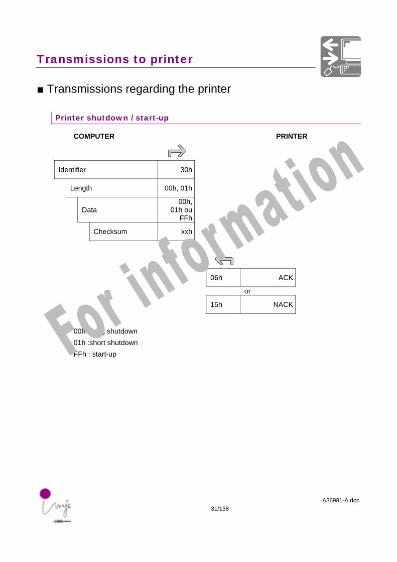
■ Transmissions regarding the printer
Printer shutdown / start-up
COMPUTER PRINTER
Identifier 30h
Length 00h, 01h
Data 00h,
01h ou FFh
Checksum xxh
06h ACK
or
15h NACK
00h : long shutdown 01h :short shutdown FFh : start-up For information
Transmissions to printer
A36981-A.doc32/138
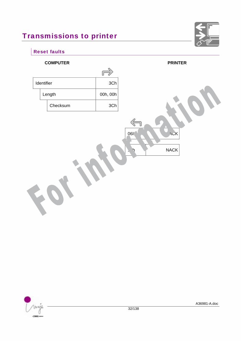
Reset faults
COMPUTER PRINTER
Identifier 3Ch
Length 00h, 00h
Checksum 3Ch
06h ACK
or
15h NACK
For information
Transmissions to printer
A36981-A.doc33/138
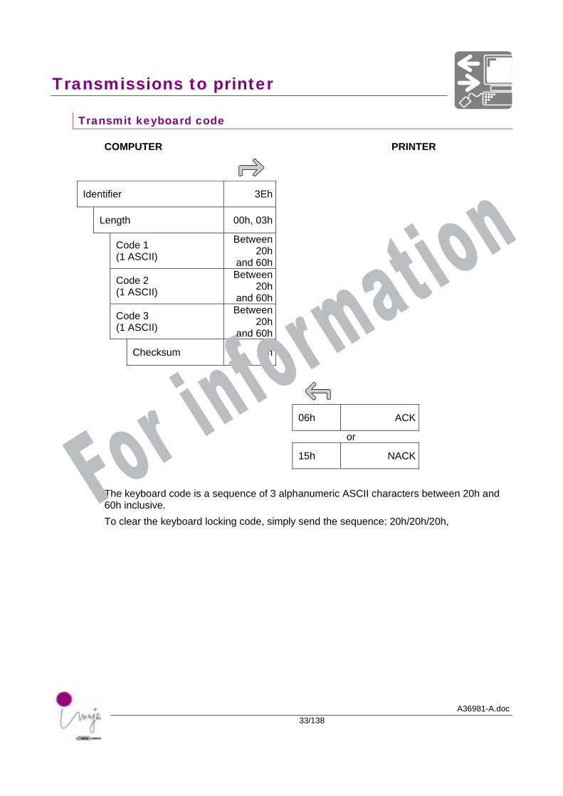
Transmit keyboard code
COMPUTER PRINTER
Identifier 3Eh
Length 00h, 03h
Code 1 (1 ASCII)
Between 20h
and 60h
Code 2 (1 ASCII)
Between 20h
and 60h
Code 3 (1 ASCII)
Between 20h
and 60h
Checksum xxh
06h ACK
or
15h NACK
The keyboard code is a sequence of 3 alphanumeric ASCII characters between 20h and 60h inclusive. To clear the keyboard locking code, simply send the sequence: 20h/20h/20h,
For information
Transmissions to printer
A36981-A.doc34/138
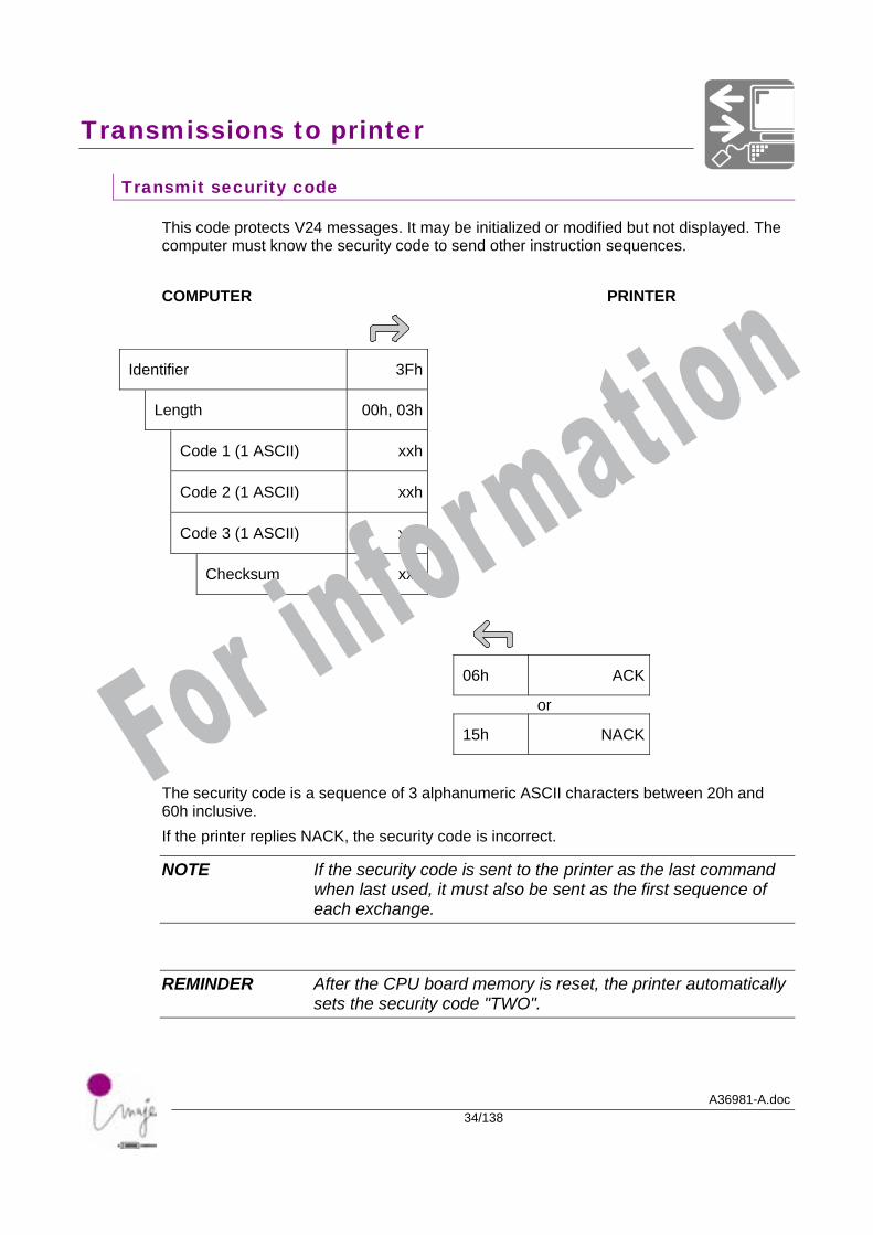
Transmit security code
This code protects V24 messages. It may be initialized or modified but not displayed. The computer must know the security code to send other instruction sequences. COMPUTER PRINTER
Identifier 3Fh
Length 00h, 03h
Code 1 (1 ASCII) xxh
Code 2 (1 ASCII) xxh
Code 3 (1 ASCII) xxh
Checksum xxh
06h ACK
or
15h NACK
The security code is a sequence of 3 alphanumeric ASCII characters between 20h and 60h inclusive. If the printer replies NACK, the security code is incorrect.
NOTE If the security code is sent to the printer as the last command when last used, it must also be sent as the first sequence of each exchange.
REMINDER After the CPU board memory is reset, the printer automatically sets the security code "TWO".
For information
Transmissions to printer
A36981-A.doc35/138
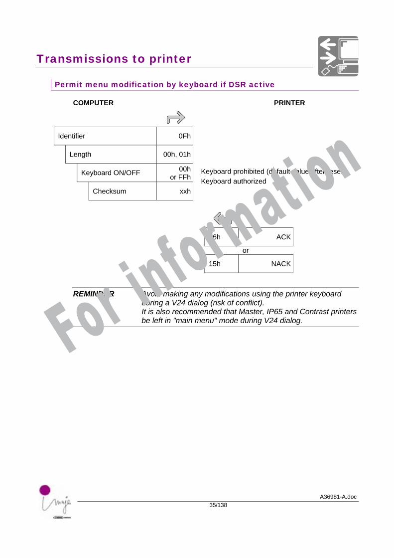
Permit menu modification by keyboard if DSR active
COMPUTER PRINTER
Identifier 0Fh
Length 00h, 01h
Keyboard ON/OFF 00hor FFh
Checksum xxh
06h ACK
or
15h NACK
REMINDER Avoid making any modifications using the printer keyboard during a V24 dialog (risk of conflict). It is also recommended that Master, IP65 and Contrast printers be left in "main menu" mode during V24 dialog.
Keyboard prohibited (default value after reset) Keyboard authorized
For information
Transmissions to printer
A36981-A.doc36/138
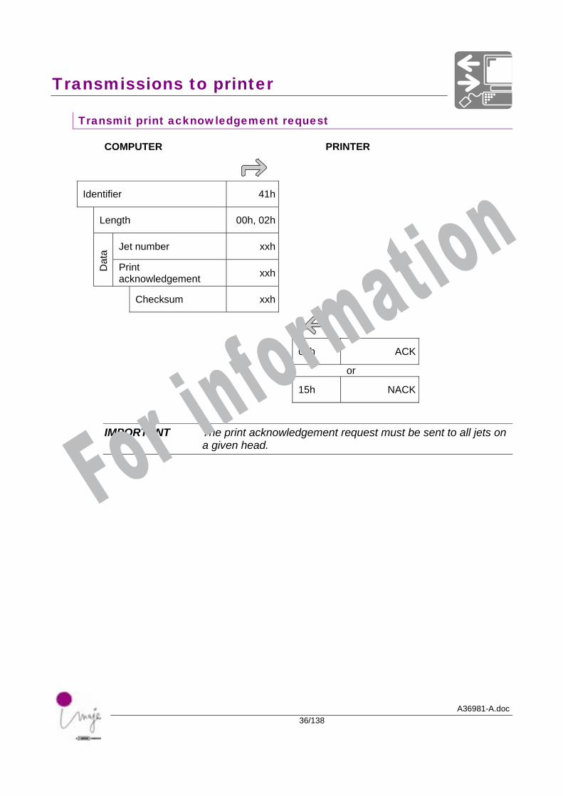
Transmit print acknowledgement request
COMPUTER PRINTER
Identifier 41h
Length 00h, 02h
Jet number xxh
Dat
a
Print acknowledgement xxh
Checksum xxh
06h ACK
or
15h NACK
IMPORTANT The print acknowledgement request must be sent to all jets on a given head. For information
Transmissions to printer
A36981-A.doc37/138
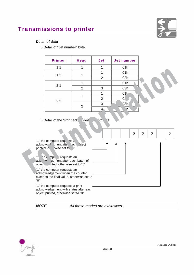
Detail of data □ Detail of "Jet number" byte
Printer Head Jet Jet number
1.1 1 1 01h 1 01h
1.2 1 2 02h
1 1 01h 2.1
2 3 03h 1 01h
1 2 02h 3 03h
2.2 2
4 04h □ Detail of the "Print acknowledgement" byte
0 0 0 0
"1" the computer requests an acknowledgement after each object printed, otherwise set to "0" "1" the computer requests an acknowledgement after each batch of objects printed, otherwise set to "0" "1" the computer requests an acknowledgement when the counter exceeds the final value, otherwise set to "0" "1" the computer requests a print acknowledgement with status after each object printed, otherwise set to "0"
NOTE All these modes are exclusives.
For information
Transmissions to printer
A36981-A.doc38/138
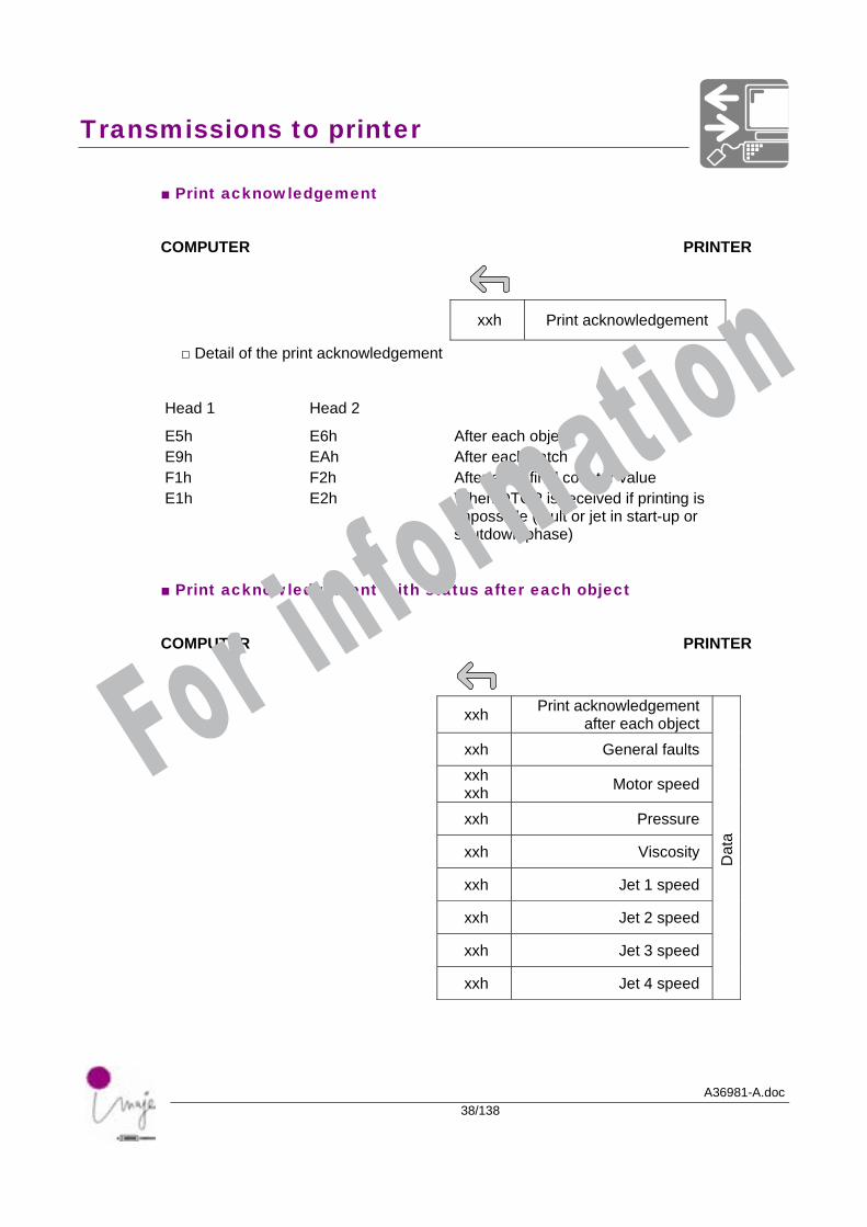
■ Print acknowledgement
COMPUTER PRINTER
xxh Print acknowledgement
□ Detail of the print acknowledgement
Head 1 Head 2
E5h E9h F1h E1h
E6h EAh F2h E2h
After each object After each batch After each final counter value When DTOP is received if printing is impossible (fault or jet in start-up or shutdown phase)
■ Print acknowledgement with status after each object
COMPUTER PRINTER
xxh Print acknowledgement after each object
xxh General faults xxh xxh Motor speed
xxh Pressure
xxh Viscosity
xxh Jet 1 speed
xxh Jet 2 speed
xxh Jet 3 speed
xxh Jet 4 speed
Dat
a
For information
Transmissions to printer
A36981-A.doc39/138
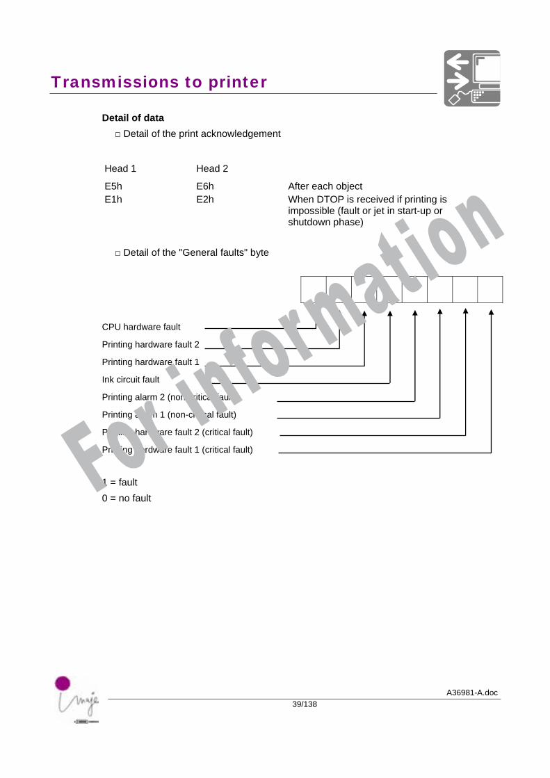
Detail of data □ Detail of the print acknowledgement
Head 1 Head 2
E5h E1h
E6h E2h
After each object When DTOP is received if printing is impossible (fault or jet in start-up or shutdown phase)
□ Detail of the "General faults" byte
CPU hardware fault
Printing hardware fault 2
Printing hardware fault 1
Ink circuit fault
Printing alarm 2 (non-critical fault)
Printing alarm 1 (non-critical fault)
Printing hardware fault 2 (critical fault)
Printing hardware fault 1 (critical fault)
1 = fault 0 = no fault For information
Transmissions to printer
A36981-A.doc40/138
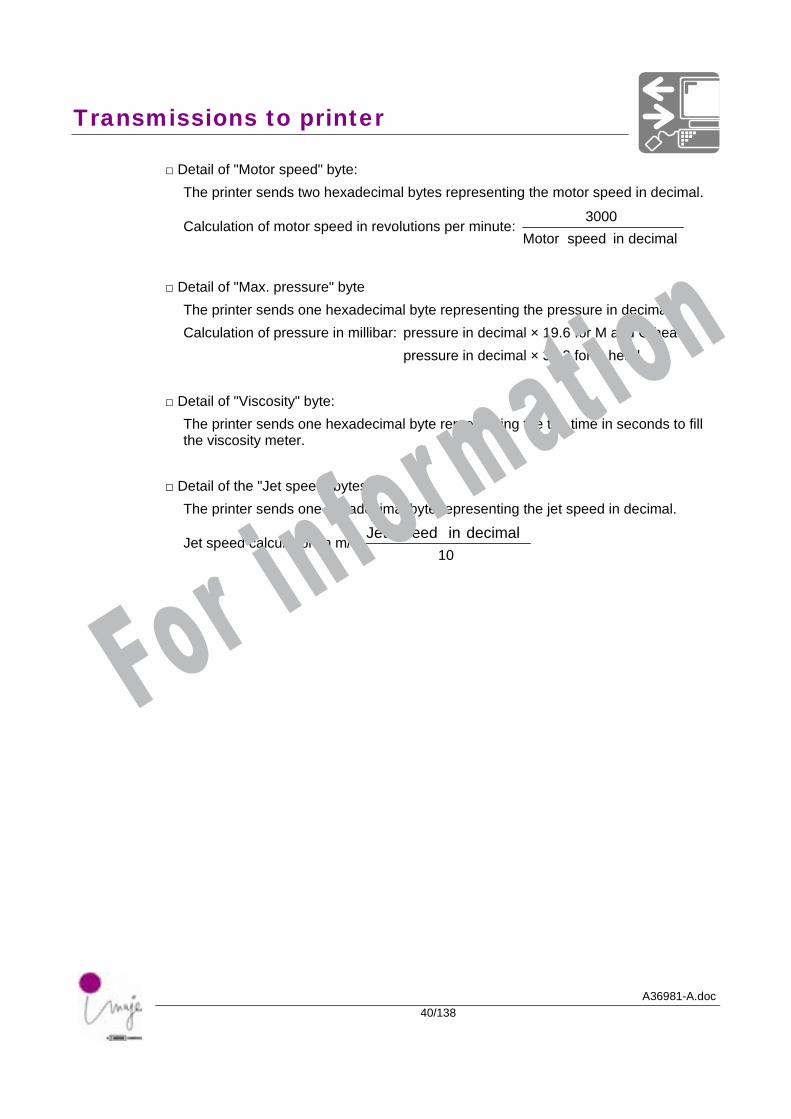
□ Detail of "Motor speed" byte: The printer sends two hexadecimal bytes representing the motor speed in decimal.
Calculation of motor speed in revolutions per minute: decimal in speed Motor
3000
□ Detail of "Max. pressure" byte
The printer sends one hexadecimal byte representing the pressure in decimal. Calculation of pressure in millibar: pressure in decimal × 19.6 for M and G heads. pressure in decimal × 39.2 for P head.
□ Detail of "Viscosity" byte: The printer sends one hexadecimal byte representing the the time in seconds to fill the viscosity meter.
□ Detail of the "Jet speed" bytes: The printer sends one hexadecimal byte representing the jet speed in decimal.
Jet speed calculation in m/s 10
decimal in speed Jet
For information
Transmissions to printer
A36981-A.doc41/138
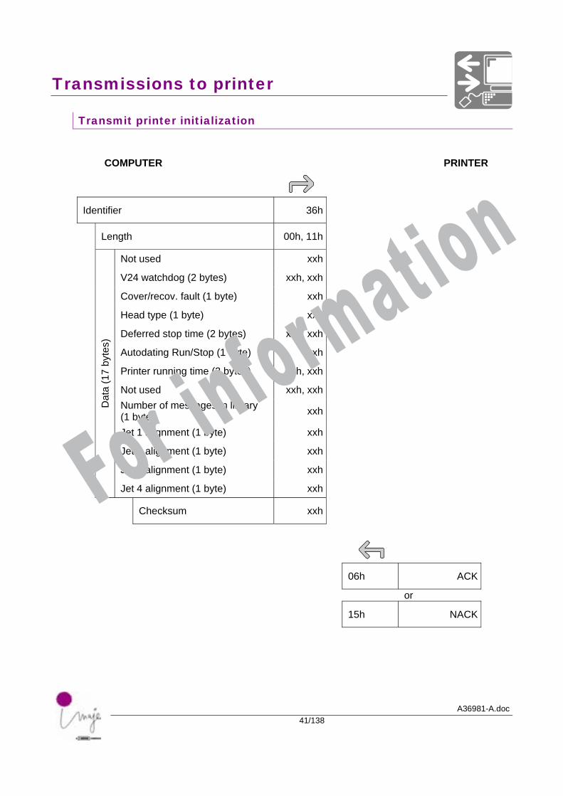
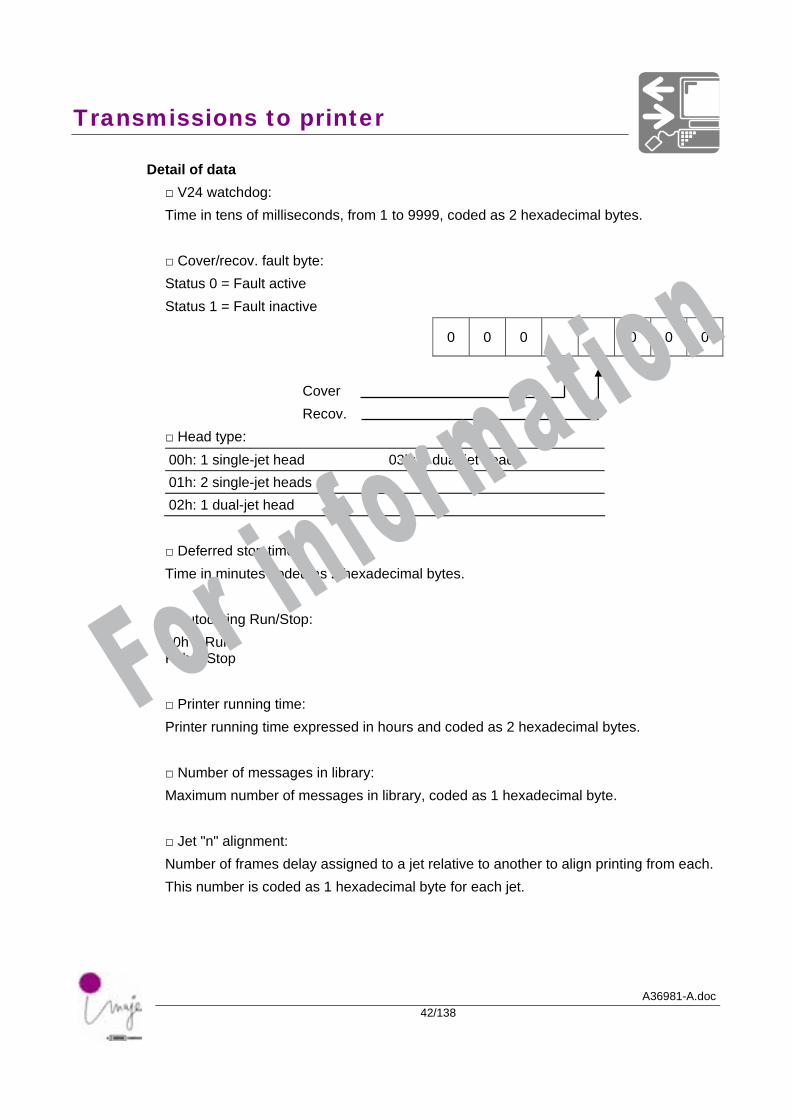
Transmit printer initialization
COMPUTER PRINTER
Identifier 36h
Length 00h, 11h
Not used xxh
V24 watchdog (2 bytes) xxh, xxh
Cover/recov. fault (1 byte) xxh
Head type (1 byte) xxh
Deferred stop time (2 bytes) xxh, xxh
Autodating Run/Stop (1 byte) xxh
Printer running time (2 bytes) xxh, xxh
Not used xxh, xxh
Number of messages in library (1 byte) xxh
Jet 1 alignment (1 byte) xxh
Jet 2 alignment (1 byte) xxh
Jet 3 alignment (1 byte) xxh
Dat
a (1
7 by
tes)
Jet 4 alignment (1 byte) xxh
Checksum xxh
06h ACK
or
15h NACK
For information
Transmissions to printer
A36981-A.doc42/138
Detail of data □ V24 watchdog: Time in tens of milliseconds, from 1 to 9999, coded as 2 hexadecimal bytes. □ Cover/recov. fault byte: Status 0 = Fault active Status 1 = Fault inactive
0 0 0 0 0 0
Cover Recov.
□ Head type: 00h: 1 single-jet head 03h: 2 dual-jet heads 01h: 2 single-jet heads 02h: 1 dual-jet head
□ Deferred stop time: Time in minutes coded as 2 hexadecimal bytes. □ Autodating Run/Stop: 00h = Run FFh = Stop
□ Printer running time: Printer running time expressed in hours and coded as 2 hexadecimal bytes. □ Number of messages in library: Maximum number of messages in library, coded as 1 hexadecimal byte. □ Jet "n" alignment: Number of frames delay assigned to a jet relative to another to align printing from each. This number is coded as 1 hexadecimal byte for each jet.
For information
Transmissions to printer
A36981-A.doc43/138
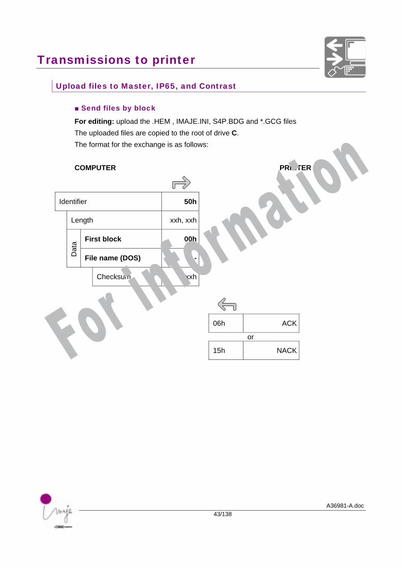
Upload files to Master, IP65, and Contrast
■ Send files by block
For editing: upload the .HEM , IMAJE.INI, S4P.BDG and *.GCG files The uploaded files are copied to the root of drive C. The format for the exchange is as follows: COMPUTER PRINTER
Identifier 50h
Length xxh, xxh
First block 00h
Dat
a
File name (DOS) - - -
Checksum xxh
06h ACK
or
15h NACK
For information
Transmissions to printer
A36981-A.doc44/138
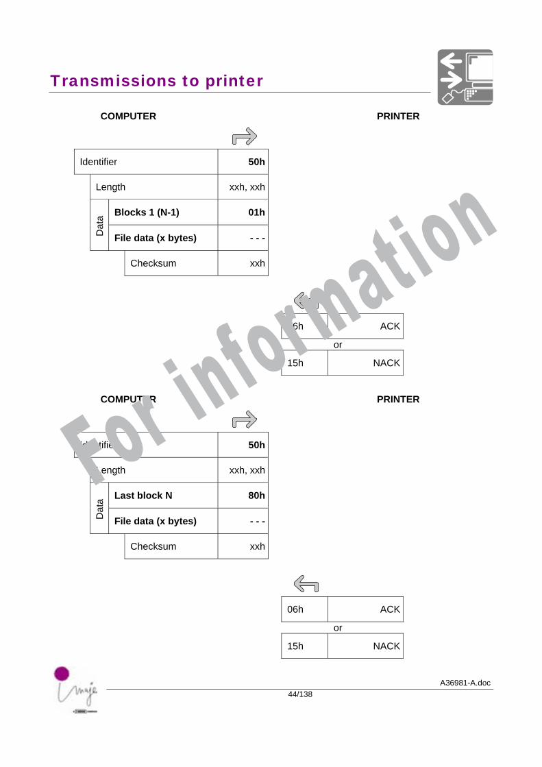
COMPUTER PRINTER
Identifier 50h
Length xxh, xxh
Blocks 1 (N-1) 01h
Dat
a
File data (x bytes) - - -
Checksum xxh
06h ACK
or
15h NACK
COMPUTER PRINTER
Identifier 50h
Length xxh, xxh
Last block N 80h
Dat
a
File data (x bytes) - - -
Checksum xxh
06h ACK
or
15h NACK
For information
Transmissions to printer
A36981-A.doc45/138
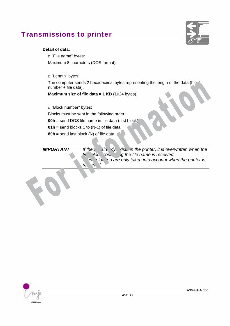
Detail of data: □ "File name" bytes: Maximum 8 characters (DOS format).
□ "Length" bytes: The computer sends 2 hexadecimal bytes representing the length of the data (block number + file data). Maximum size of file data = 1 KB (1024 bytes).
□ "Block number" bytes: Blocks must be sent in the following order: 00h = send DOS file name in file data (first block), 01h = send blocks 1 to (N-1) of file data 80h = send last block (N) of file data
IMPORTANT If the file already exists in the printer, it is overwritten when the first block containing the file name is received. Files uploaded are only taken into account when the printer is restarted.
For information
Transmissions to printer
A36981-A.doc46/138
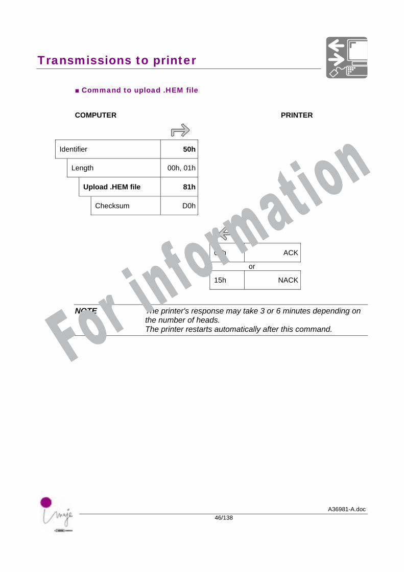
■ Command to upload .HEM file
COMPUTER PRINTER
Identifier 50h
Length 00h, 01h
Upload .HEM file 81h
Checksum D0h
06h ACK
or
15h NACK
NOTE The printer's response may take 3 or 6 minutes depending on the number of heads. The printer restarts automatically after this command. For information
Transmissions to printer
A36981-A.doc47/138
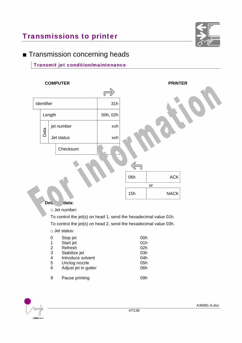
■ Transmission concerning heads Transmit jet condition/maintenance
COMPUTER PRINTER
Identifier 31h
Length 00h, 02h
jet number xxh
Dat
a
Jet status xxh
Checksum xxh
06h ACK
or
15h NACK
Detail of data: □ Jet number: To control the jet(s) on head 1, send the hexadecimal value 01h. To control the jet(s) on head 2, send the hexadecimal value 03h. □ Jet status: 0 Stop jet 00h 1 Start jet 01h 2 Refresh 02h 3 Stabilize jet 03h 4 Introduce solvent 04h 5 Unclog nozzle 05h 6 Adjust jet in gutter 06h 9 Pause printing 09h
For information
Transmissions to printer
A36981-A.doc48/138
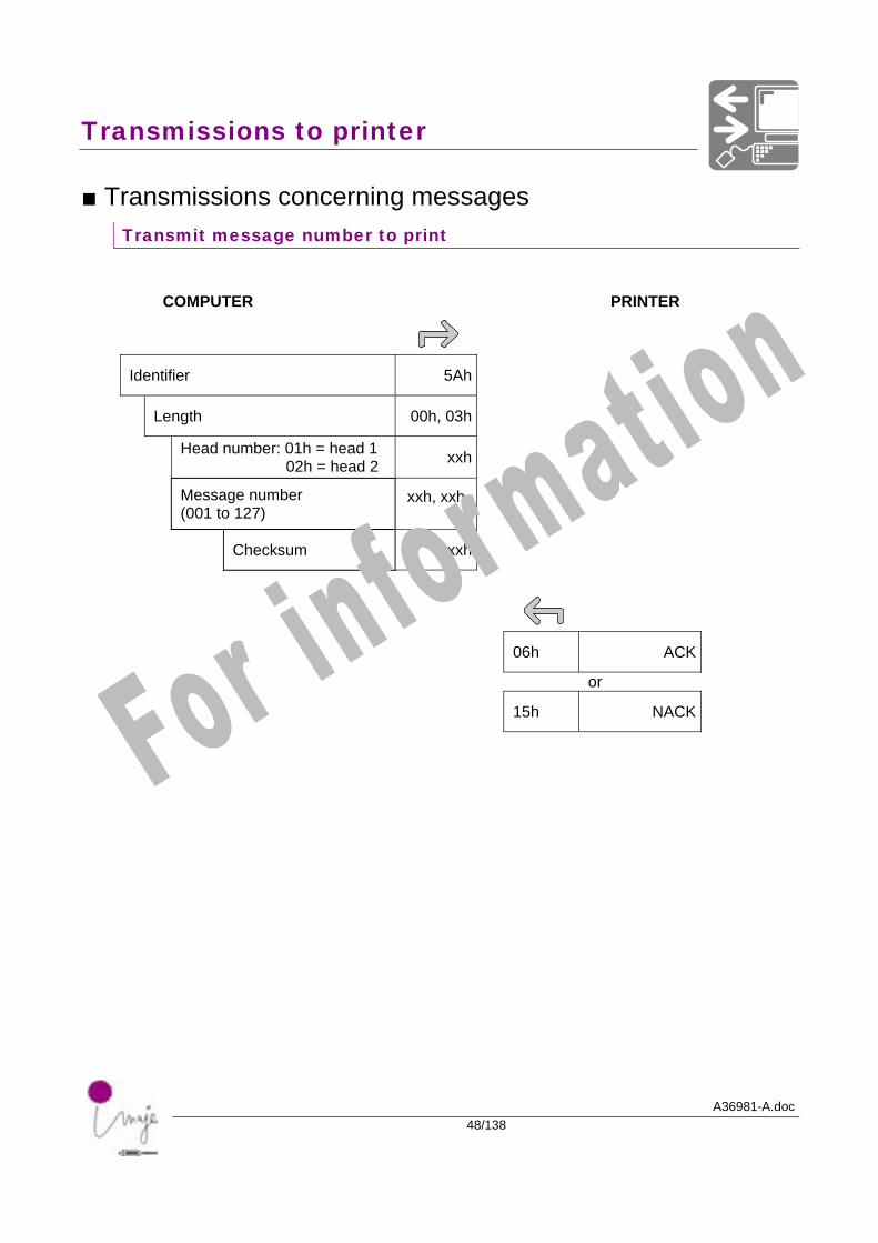
■ Transmissions concerning messages Transmit message number to print
COMPUTER PRINTER
Identifier 5Ah
Length 00h, 03h
Head number: 01h = head 1 02h = head 2 xxh
Message number (001 to 127)
xxh, xxh
Checksum xxh
06h ACK
or
15h NACK For information
Transmissions to printer
A36981-A.doc49/138
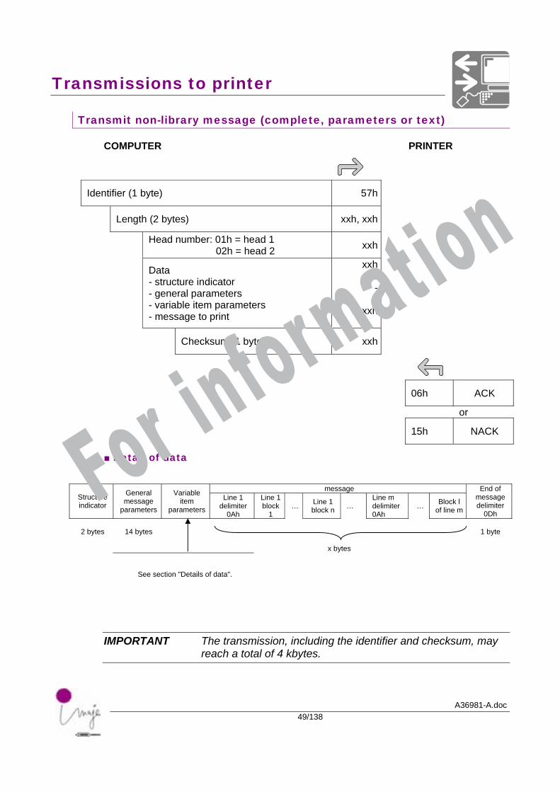
Transmit non-library message (complete, parameters or text)
COMPUTER PRINTER
Identifier (1 byte) 57h
Length (2 bytes) xxh, xxh
Head number: 01h = head 1 02h = head 2 xxh
Data - structure indicator - general parameters - variable item parameters - message to print
xxh---
xxh
Checksum (1 byte) xxh
06h ACK
or
15h NACK
■ Detail of data
message
Structure indicator
General message
parameters
Variable item
parameters
Line 1 delimiter
0Ah
Line 1 block
1 … Line 1
block n … Line m delimiter 0Ah
… Block l of line m
End of message delimiter
0Dh
2 bytes 14 bytes 1 byte
x bytes
See section "Details of data".
IMPORTANT The transmission, including the identifier and checksum, may reach a total of 4 kbytes.
For information
Transmissions to printer
A36981-A.doc50/138
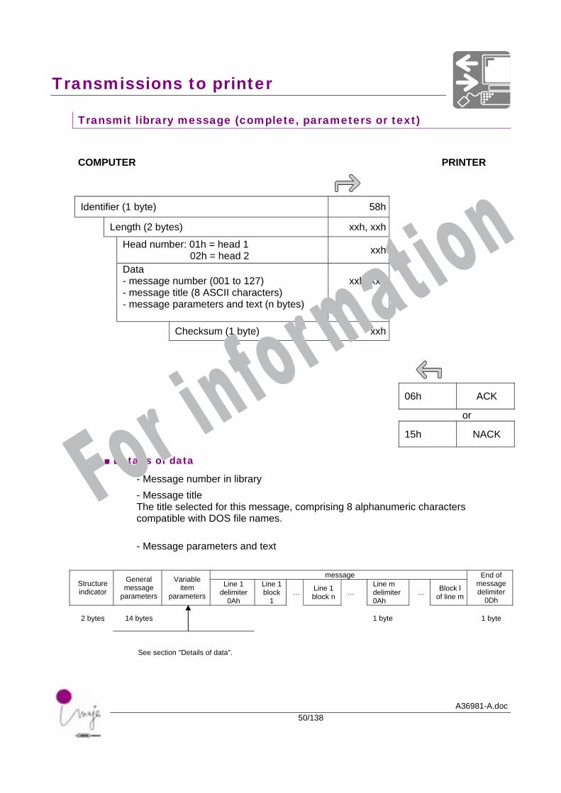
Transmit library message (complete, parameters or text)
COMPUTER PRINTER
Identifier (1 byte) 58h
Length (2 bytes) xxh, xxh
Head number: 01h = head 1 02h = head 2 xxh
Data - message number (001 to 127) - message title (8 ASCII characters) - message parameters and text (n bytes)
xxh, xxh
Checksum (1 byte) xxh
06h ACK
or
15h NACK
■ Details of data
- Message number in library - Message title The title selected for this message, comprising 8 alphanumeric characters compatible with DOS file names. - Message parameters and text
message Structure indicator
General message
parameters
Variable item
parameters
Line 1 delimiter
0Ah
Line 1 block
1 … Line 1
block n … Line m delimiter 0Ah
… Block l of line m
End of message delimiter
0Dh
2 bytes 14 bytes 1 byte 1 byte
See section "Details of data".
For information
Transmissions to printer
A36981-A.doc51/138
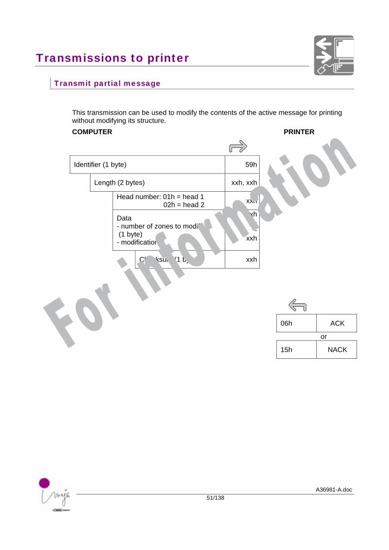
Transmit partial message
This transmission can be used to modify the contents of the active message for printing without modifying its structure. COMPUTER PRINTER
Identifier (1 byte) 59h
Length (2 bytes) xxh, xxh
Head number: 01h = head 1 02h = head 2 xxh
Data - number of zones to modify (1 byte) - modification
xxh--
xxh
Checksum (1 byte) xxh
06h ACK
or
15h NACK For information
Transmissions to printer
A36981-A.doc52/138
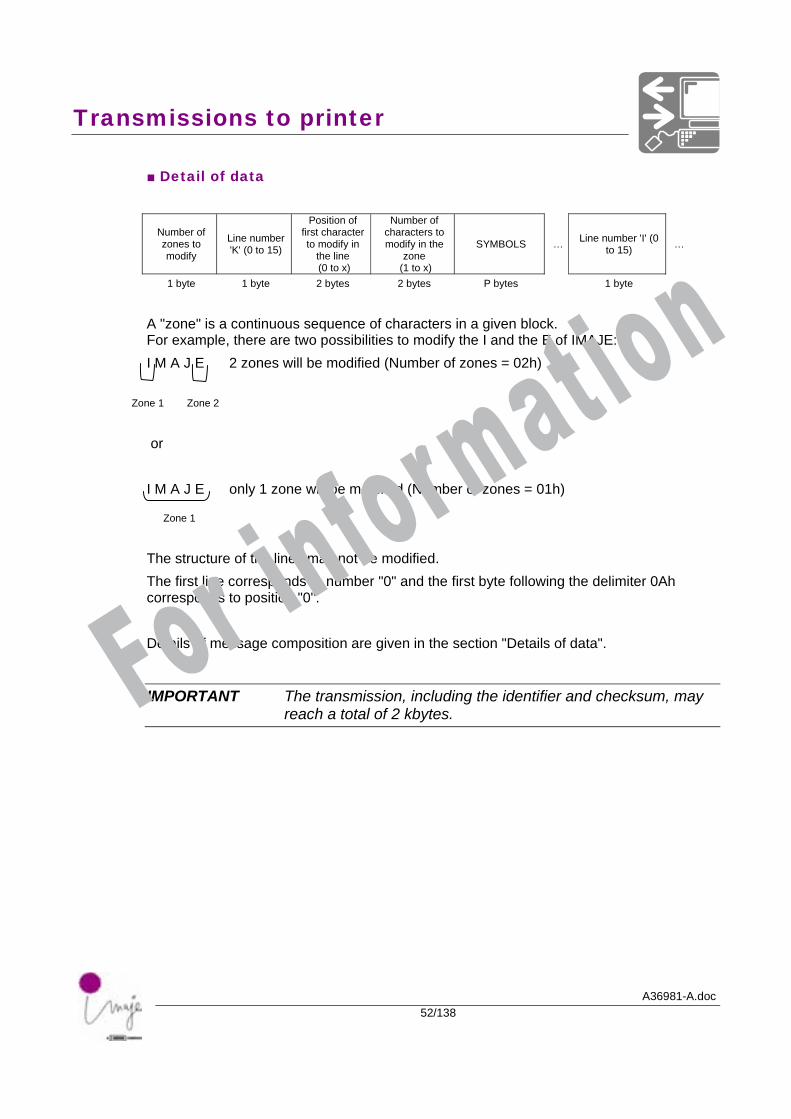
■ Detail of data
Number of zones to modify
Line number 'K' (0 to 15)
Position of first character to modify in
the line (0 to x)
Number of characters to modify in the
zone (1 to x)
SYMBOLS … Line number 'I' (0 to 15) …
1 byte 1 byte 2 bytes 2 bytes P bytes 1 byte
A "zone" is a continuous sequence of characters in a given block. For example, there are two possibilities to modify the I and the E of IMAJE: I M A J E 2 zones will be modified (Number of zones = 02h)
Zone 1 Zone 2
or I M A J E only 1 zone will be modified (Number of zones = 01h)
Zone 1
The structure of the lines may not be modified. The first line corresponds to number "0" and the first byte following the delimiter 0Ah corresponds to position "0". Details of message composition are given in the section "Details of data".
IMPORTANT The transmission, including the identifier and checksum, may reach a total of 2 kbytes. For information
Transmissions to printer
A36981-A.doc53/138
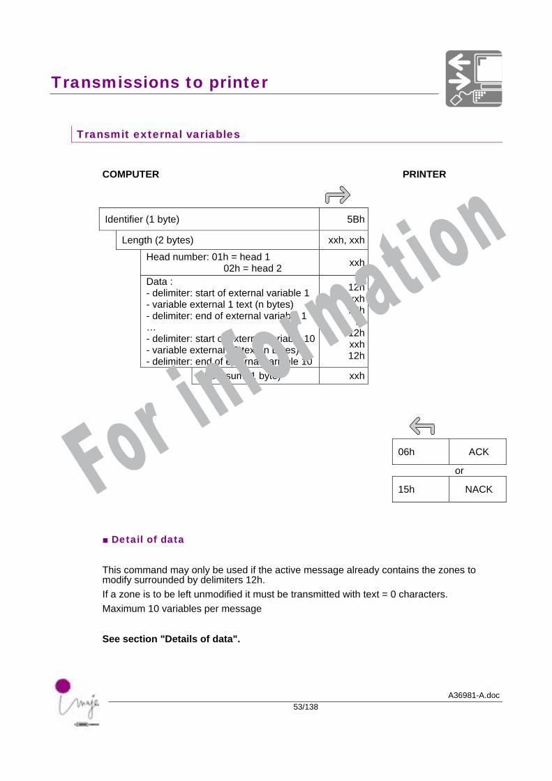
Transmit external variables
COMPUTER PRINTER
Identifier (1 byte) 5Bh
Length (2 bytes) xxh, xxh
Head number: 01h = head 1 02h = head 2 xxh
Data : - delimiter: start of external variable 1 - variable external 1 text (n bytes) - delimiter: end of external variable 1 … - delimiter: start of external variable 10- variable external 10 text (n bytes) - delimiter: end of external variable 10
12hxxh12h
…12hxxh12h
Checksum (1 byte) xxh
06h ACK
or
15h NACK
■ Detail of data This command may only be used if the active message already contains the zones to modify surrounded by delimiters 12h. If a zone is to be left unmodified it must be transmitted with text = 0 characters. Maximum 10 variables per message See section "Details of data".
For information
Transmissions to printer
A36981-A.doc54/138
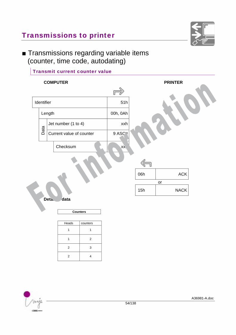
■ Transmissions regarding variable items (counter, time code, autodating)
Transmit current counter value
COMPUTER PRINTER
Identifier 51h
Length 00h, 0Ah
Jet number (1 to 4) xxh
Dat
a
Current value of counter 9 ASCII
Checksum xxh
06h ACK
or
15h NACK
Detail of data
Counters
Heads counters
1 1
1 2
2 3
2 4
For information
Transmissions to printer
A36981-A.doc55/138
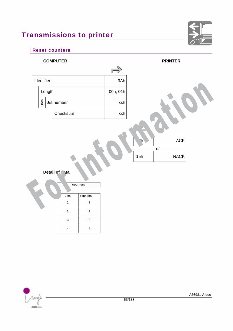
Reset counters
COMPUTER PRINTER
Identifier 3Ah
Length 00h, 01h
Dat
a Jet number xxh
Checksum xxh
06h ACK
or
15h NACK
Detail of data
counters
Jets counters
1 1
2 2
3 3
4 4
For information
Transmissions to printer
A36981-A.doc56/138
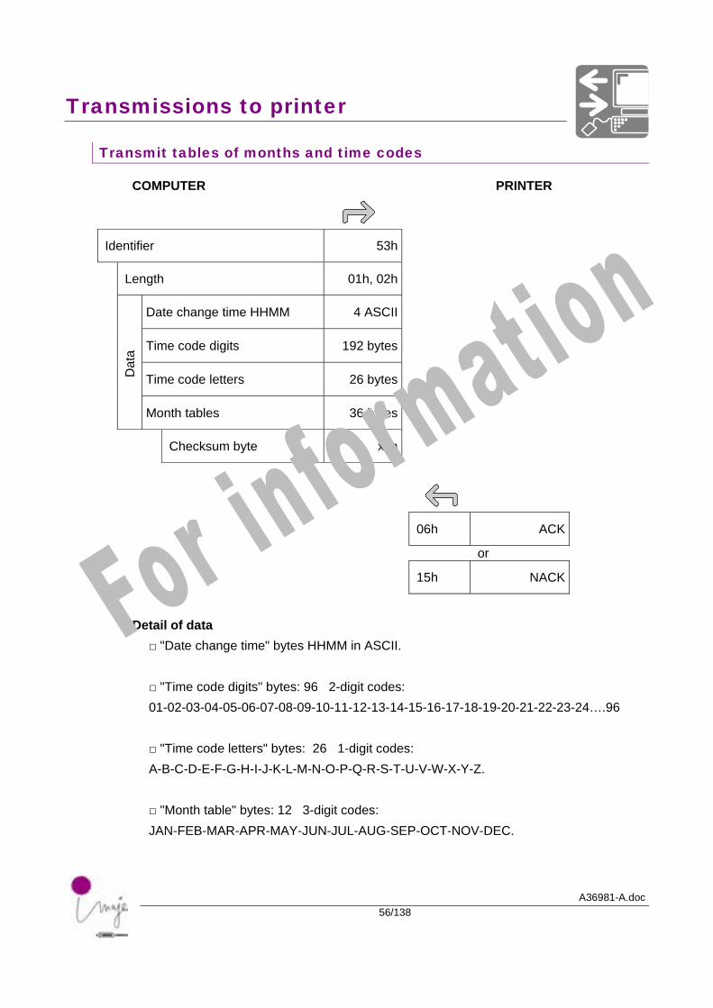
Transmit tables of months and time codes
COMPUTER PRINTER
Identifier 53h
Length 01h, 02h
Date change time HHMM 4 ASCII
Time code digits 192 bytes
Time code letters 26 bytes
Dat
a
Month tables 36 bytes
Checksum byte xxh
06h ACK
or
15h NACK
Detail of data
□ "Date change time" bytes HHMM in ASCII.
□ "Time code digits" bytes: 96 2-digit codes: 01-02-03-04-05-06-07-08-09-10-11-12-13-14-15-16-17-18-19-20-21-22-23-24….96
□ "Time code letters" bytes: 26 1-digit codes: A-B-C-D-E-F-G-H-I-J-K-L-M-N-O-P-Q-R-S-T-U-V-W-X-Y-Z.
□ "Month table" bytes: 12 3-digit codes: JAN-FEB-MAR-APR-MAY-JUN-JUL-AUG-SEP-OCT-NOV-DEC.
For information
Transmissions to printer
A36981-A.doc57/138
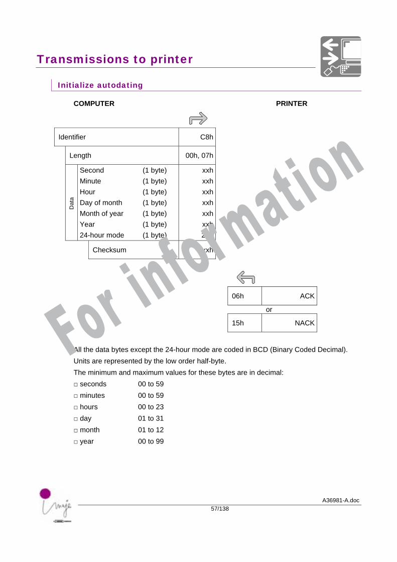
Initialize autodating
COMPUTER PRINTER
Identifier C8h
Length 00h, 07h
Dat
a
Second (1 byte) Minute (1 byte) Hour (1 byte) Day of month (1 byte) Month of year (1 byte) Year (1 byte) 24-hour mode (1 byte)
xxhxxhxxhxxhxxhxxh20h
Checksum xxh
06h ACK
or
15h NACK
All the data bytes except the 24-hour mode are coded in BCD (Binary Coded Decimal). Units are represented by the low order half-byte. The minimum and maximum values for these bytes are in decimal: □ seconds 00 to 59 □ minutes 00 to 59 □ hours 00 to 23 □ day 01 to 31 □ month 01 to 12 □ year 00 to 99
For information
Transmissions to printer
A36981-A.doc58/138
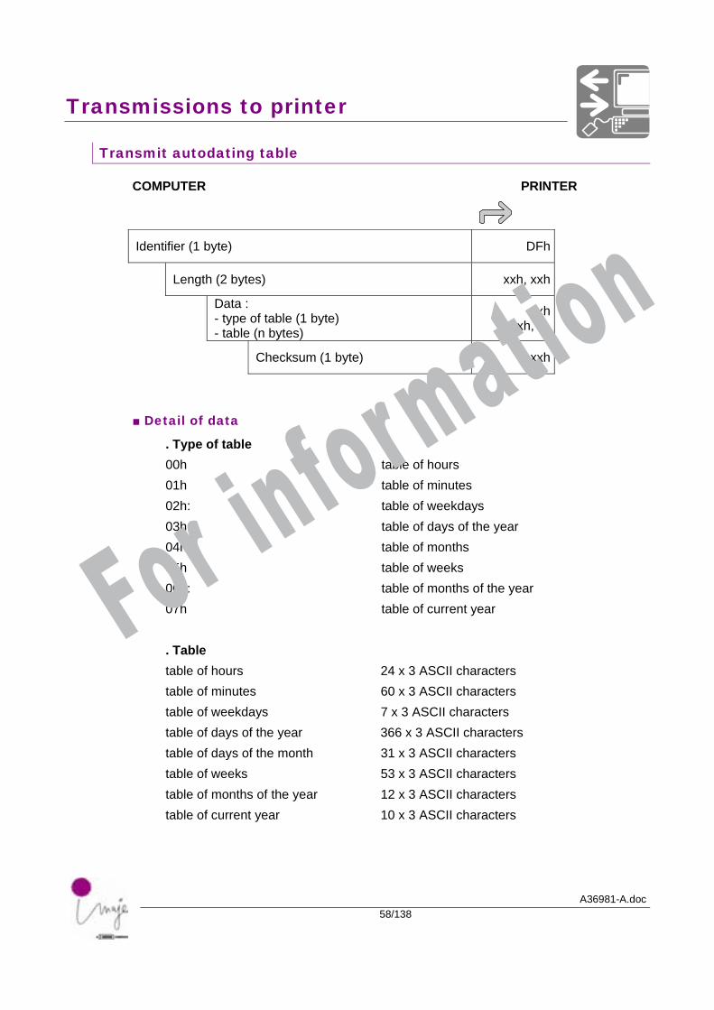
Transmit autodating table
COMPUTER PRINTER
Identifier (1 byte) DFh
Length (2 bytes) xxh, xxh
Data : - type of table (1 byte) - table (n bytes)
xxh xxh, …
Checksum (1 byte) xxh
■ Detail of data
. Type of table 00h table of hours 01h table of minutes 02h: table of weekdays 03h: table of days of the year 04h: table of months 05h table of weeks 06h: table of months of the year 07h table of current year . Table table of hours 24 x 3 ASCII characters table of minutes 60 x 3 ASCII characters table of weekdays 7 x 3 ASCII characters table of days of the year 366 x 3 ASCII characters table of days of the month 31 x 3 ASCII characters table of weeks 53 x 3 ASCII characters table of months of the year 12 x 3 ASCII characters table of current year 10 x 3 ASCII characters
For information
A36981-A.doc59/138
Requests to the printer
For information

Requests to the printer
A36981-A.doc60/138
For information
Requests to the printer
A36981-A.doc61/138
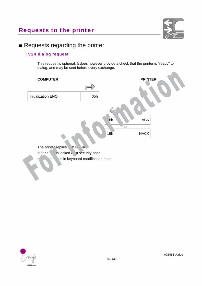
■ Requests regarding the printer V24 dialog request
This request is optional. It does however provide a check that the printer is "ready" to dialog, and may be sent before every exchange. COMPUTER PRINTER
Initialization ENQ 05h
06h ACK
or
15h NACK
The printer replies with NACK: □ if the link is locked by a security code, □ if the menu is in keyboard modification mode. For information
Requests to the printer
A36981-A.doc62/138
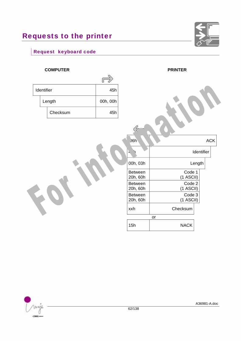
Request keyboard code
COMPUTER PRINTER
Identifier 45h
Length 00h, 00h
Checksum 45h
06h ACK
45h Identifier
00h, 03h Length
Between 20h, 60h
Code 1 (1 ASCII)
Between 20h, 60h
Code 2 (1 ASCII)
Between 20h, 60h
Code 3 (1 ASCII)
xxh Checksum
or
15h NACK
For information
Requests to the printer
A36981-A.doc63/138
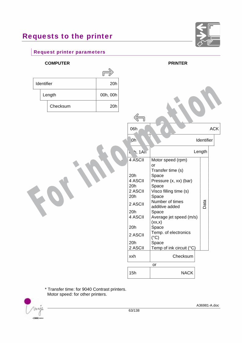
Request printer parameters
COMPUTER PRINTER
Identifier 20h
Length 00h, 00h
Checksum 20h
06h ACK
20h Identifier
00h, 1Ah Length
4 ASCII Motor speed (rpm) or Transfer time (s) 20h Space 4 ASCII Pressure (x, xx) (bar) 20h Space 2 ASCII Visco filling time (s) 20h Space
2 ASCII Number of times additive added
20h Space 4 ASCII Average jet speed (m/s)
(xx,x)
20h Space
2 ASCII Temp. of electronics (°C)
20h Space 2 ASCII Temp of ink circuit (°C)
Dat
a
xxh Checksum
or
15h NACK
* Transfer time: for 9040 Contrast printers. Motor speed: for other printers.
*
For information
Requests to the printer
A36981-A.doc64/138
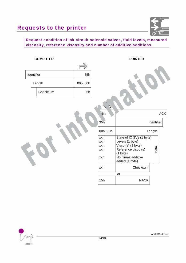
Request condition of ink circuit solenoid valves, fluid levels, measured viscosity, reference viscosity and number of additive additions.
COMPUTER PRINTER
Identifier 35h
Length 00h, 00h
Checksum 35h
06h ACK
35h Identifier
00h, 05h Length
xxh State of IC SVs (1 byte) xxh Levels (1 byte) xxh Visco (s) (1 byte) xxh Reference visco (s)
(1 byte)
xxh No. times additive added (1 byte)
Dat
a
xxh Checksum
or
15h NACK
For information
Requests to the printer
A36981-A.doc65/138
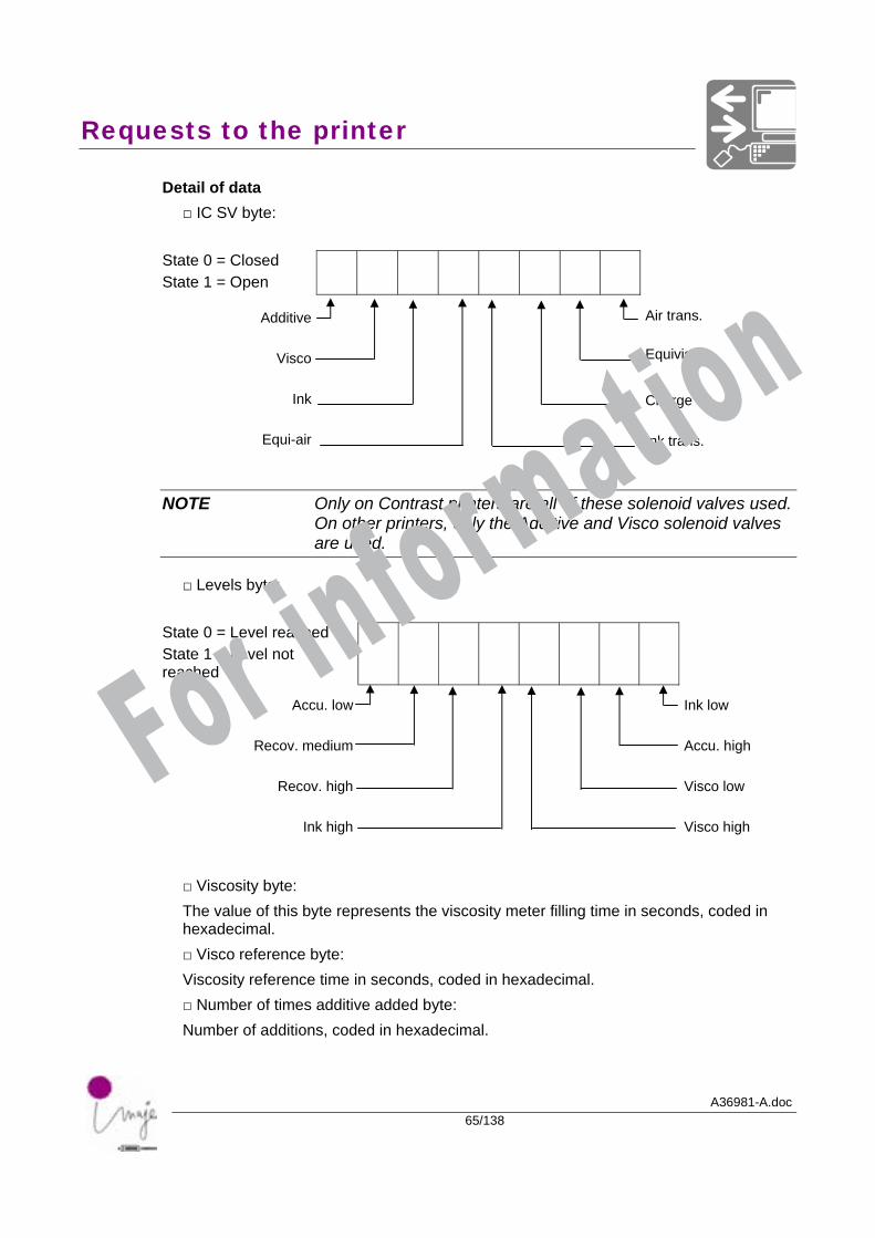
Detail of data □ IC SV byte:
State 0 = Closed State 1 = Open
Additive
Air trans.
Visco Equivisc
Ink
Charge
Equi-air
Ink trans.
NOTE Only on Contrast printers are all of these solenoid valves used. On other printers, only the Additive and Visco solenoid valves are used.
□ Levels byte:
State 0 = Level reached State 1 = Level not reached
Accu. low
Ink low
Recov. medium
Accu. high
Recov. high
Visco low
Ink high
Visco high
□ Viscosity byte: The value of this byte represents the viscosity meter filling time in seconds, coded in hexadecimal. □ Visco reference byte: Viscosity reference time in seconds, coded in hexadecimal. □ Number of times additive added byte: Number of additions, coded in hexadecimal.
For information
Requests to the printer
A36981-A.doc66/138
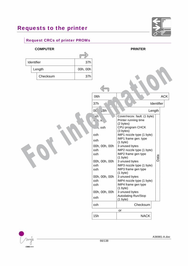
Request CRCs of printer PROMs
COMPUTER PRINTER
Identifier 37h
Length 00h, 00h
Checksum 37h
06h ACK
37h Identifier
00h, 1Bh Length xxh Cover/recov. fault. (1 byte) xxh, xxh Printer running time
(2 bytes)
xxh, xxh CPU program CHCK (3 bytes)
xxh IMP1 nozzle type (1 byte)
xxh IMP1 frame gen. type (1 byte)
00h, 00h, 00h 3 unused bytes xxh IMP2 nozzle type (1 byte) xxh IMP2 frame gen type
(1 byte)
00h, 00h, 00h 3 unused bytes xxh IMP3 nozzle type (1 byte) xxh IMP3 frame gen type
(1 byte)
00h, 00h, 00h 3 unused bytes xxh IMP4 nozzle type (1 byte) xxh IMP4 frame gen type
(1 byte)
00h, 00h, 00h 3 unused bytes xxh Autodating Run/Stop
(1 byte)
Dat
a
xxh Checksum or 15h NACK
For information
Requests to the printer
A36981-A.doc67/138
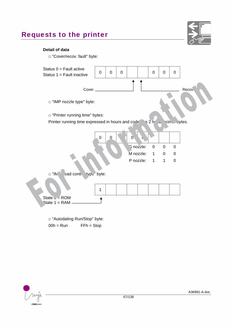
Detail of data □ "Cover/recov. fault" byte:
Status 0 = Fault active Status 1 = Fault inactive 0 0 0 0 0 0
Cover
Recov. □ "IMP nozzle type" byte:
□ "Printer running time" bytes: Printer running time expressed in hours and coded as 2 hexadecimal bytes.
0 0 0 0 0
G nozzle: 0 0 0 M nozzle: 1 0 0 P nozzle: 1 1 0
□ "IMP head control type" byte: 1
State 0 = ROM State 1 = RAM
□ "Autodating Run/Stop" byte: 00h = Run FFh = Stop
For information
Requests to the printer
A36981-A.doc68/138
Request printer faults
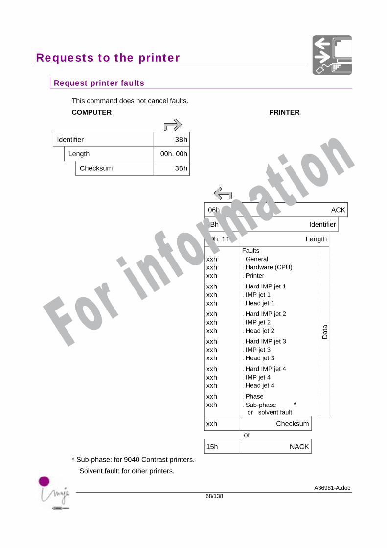
This command does not cancel faults. COMPUTER PRINTER
Identifier 3Bh
Length 00h, 00h
Checksum 3Bh
06h ACK
3Bh Identifier
00h, 11h Length Faults xxh . General xxh . Hardware (CPU) xxh . Printer
xxh . Hard IMP jet 1 xxh . IMP jet 1 xxh . Head jet 1
xxh . Hard IMP jet 2 xxh . IMP jet 2 xxh . Head jet 2
xxh . Hard IMP jet 3 xxh . IMP jet 3 xxh . Head jet 3
xxh . Hard IMP jet 4 xxh . IMP jet 4 xxh . Head jet 4
xxh . Phase xxh . Sub-phase *
or solvent fault
Dat
a
xxh Checksum or 15h NACK
* Sub-phase: for 9040 Contrast printers. Solvent fault: for other printers.
For information
Requests to the printer
A36981-A.doc69/138
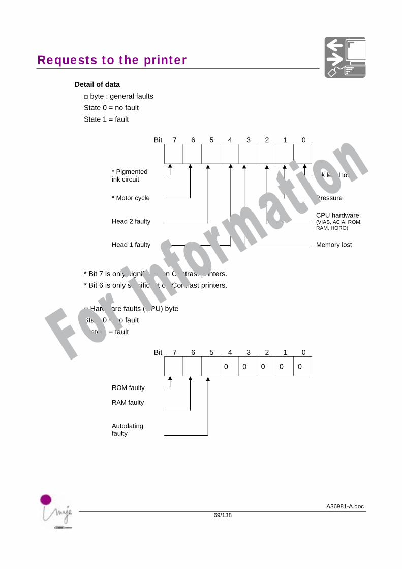
Detail of data □ byte : general faults State 0 = no fault State 1 = fault
Bit 7 6 5 4 3 2 1 0
* Pigmented ink circuit
Ink level low
* Motor cycle
Pressure
Head 2 faulty CPU hardware
(VIAS, ACIA, ROM, RAM, HORO)
Head 1 faulty
Memory lost
* Bit 7 is only significant on Contrast printers. * Bit 6 is only significant on Contrast printers. □ Hardware faults (CPU) byte State 0 = no fault State 1 = fault
Bit 7 6 5 4 3 2 1 0 0 0 0 0 0
ROM faulty
RAM faulty
Autodating faulty
For information
Requests to the printer
A36981-A.doc70/138
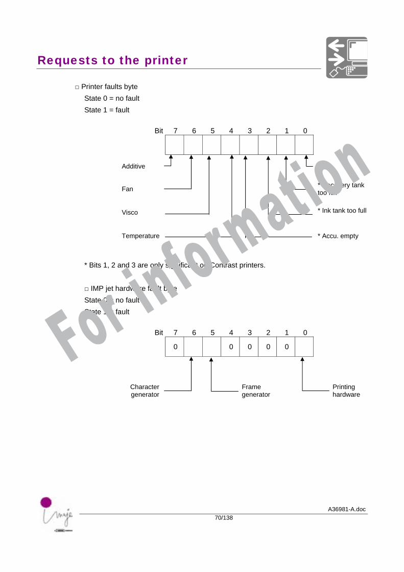
□ Printer faults byte State 0 = no fault State 1 = fault
Bit 7 6 5 4 3 2 1 0
Additive
V24
Fan * Recovery tank
too full
Visco
* Ink tank too full
Temperature
* Accu. empty
* Bits 1, 2 and 3 are only significant on Contrast printers. □ IMP jet hardware fault byte State 0 = no fault State 1 = fault
Bit 7 6 5 4 3 2 1 0 0 0 0 0 0
Character generator
Frame generator
Printing hardware
For information
Requests to the printer
A36981-A.doc71/138
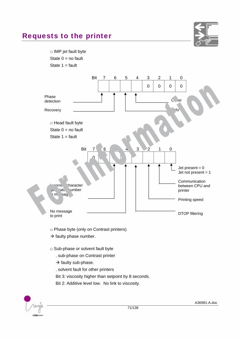
□ IMP jet fault byte State 0 = no fault State 1 = fault
Bit 7 6 5 4 3 2 1 0 0 0 0 0
Phase detection
Cover
Recovery EHV
□ Head fault byte State 0 = no fault State 1 = fault
Bit 7 6 5 4 3 2 1 0 0 0
Jet present = 0 Jet not present = 1
Communication between CPU and printer
Incorrect character generator number in message
Printing speed
No message to print
DTOP filtering
□ Phase byte (only on Contrast printers)
faulty phase number.
□ Sub-phase or solvent fault byte . sub-phase on Contrast printer
faulty sub-phase. . solvent fault for other printers Bit 3: viscosity higher than setpoint by 8 seconds. Bit 2: Additive level low. No link to viscosity.
For information
Requests to the printer
A36981-A.doc72/138
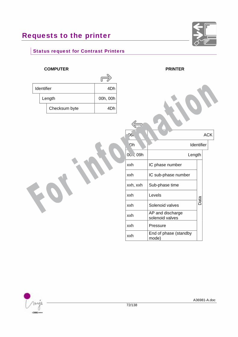
Status request for Contrast Printers
COMPUTER PRINTER
Identifier 4Dh
Length 00h, 00h
Checksum byte 4Dh
06h ACK
4Dh Identifier
00h, 09h Length
xxh IC phase number
xxh IC sub-phase number
xxh, xxh Sub-phase time
xxh Levels
xxh Solenoid valves
xxh AP and discharge solenoid valves
xxh Pressure
xxh End of phase (standby mode)
Dat
a
For information
Requests to the printer
A36981-A.doc73/138
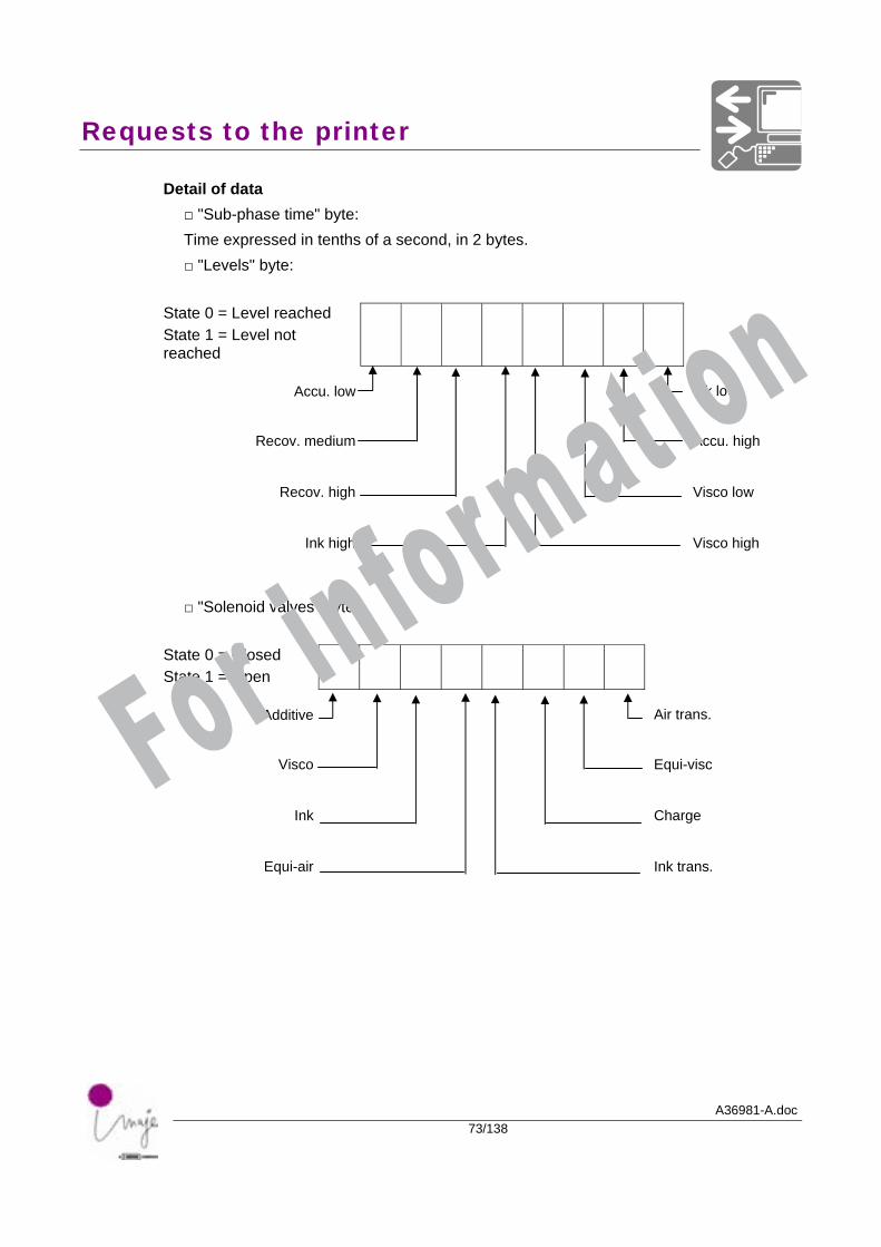
Detail of data □ "Sub-phase time" byte: Time expressed in tenths of a second, in 2 bytes. □ "Levels" byte:
State 0 = Level reached State 1 = Level not reached
Accu. low
Ink low
Recov. medium
Accu. high
Recov. high
Visco low
Ink high
Visco high
□ "Solenoid valves" byte:
State 0 = Closed State 1 = Open
Additive
Air trans.
Visco
Equi-visc
Ink
Charge
Equi-air
Ink trans.
For information
Requests to the printer
A36981-A.doc74/138
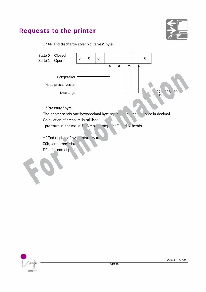
□ "AP and discharge solenoid valves" byte:
State 0 = Closed State 1 = Open 0 0 0 0
Compressor
Head pressurization
Discharge AP ( atmospheric
pressure )
□ "Pressure" byte: The printer sends one hexadecimal byte representing the pressure in decimal. Calculation of pressure in millibar: . pressure in decimal × 19.6 mb per step, for G and M heads. □ "End of phase" byte: (standby mode) 00h, for current phase. FFh, for end of phase.
For information
Requests to the printer
A36981-A.doc75/138
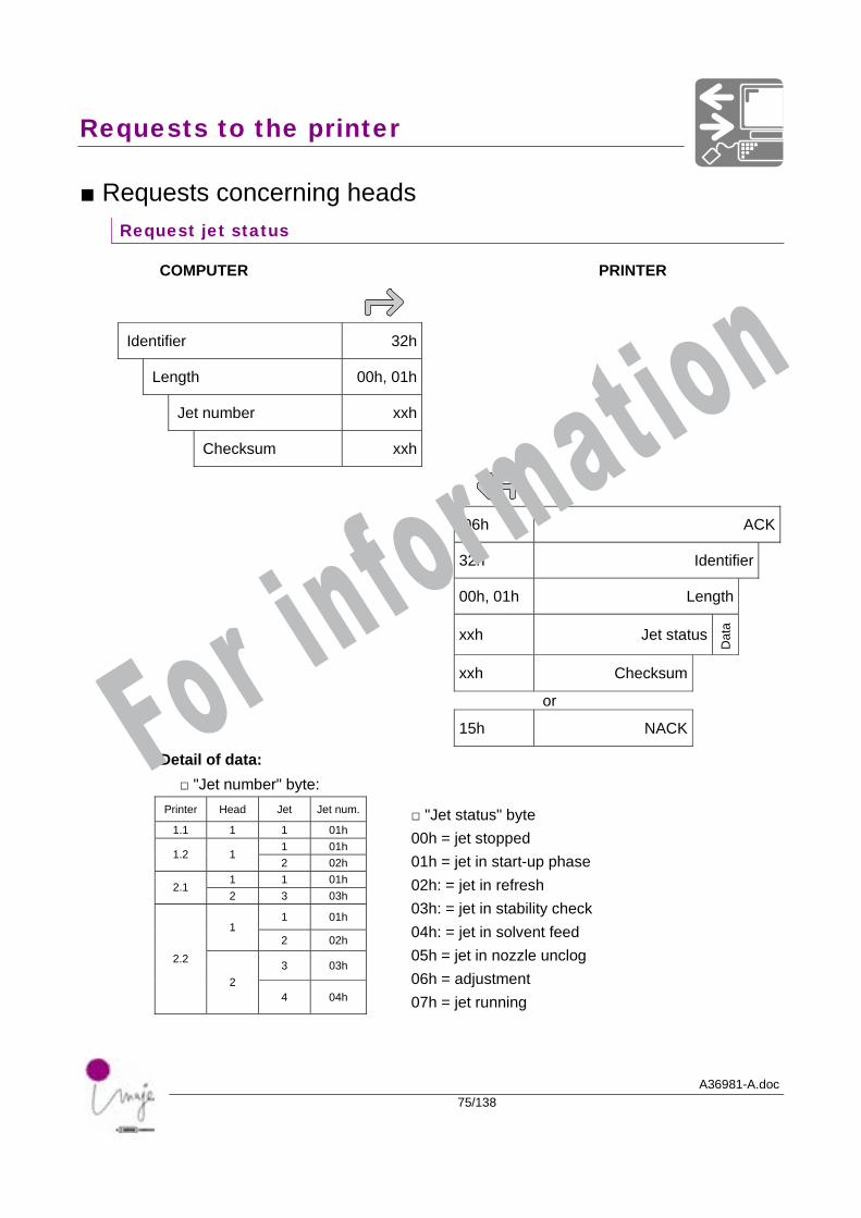
■ Requests concerning heads Request jet status
COMPUTER PRINTER
Identifier 32h
Length 00h, 01h
Jet number xxh
Checksum xxh
06h ACK
32h Identifier
00h, 01h Length
xxh Jet status
Dat
a
xxh Checksum
or
15h NACK
Detail of data: □ "Jet number" byte:
Printer Head Jet Jet num.
1.1 1 1 01h 1 01h
1.2 1 2 02h
1 1 01h 2.1
2 3 03h
1 01h 1
2 02h
3 03h 2.2
2 4 04h
□ "Jet status" byte 00h = jet stopped 01h = jet in start-up phase 02h: = jet in refresh 03h: = jet in stability check 04h: = jet in solvent feed 05h = jet in nozzle unclog 06h = adjustment 07h = jet running
For information
Requests to the printer
A36981-A.doc76/138
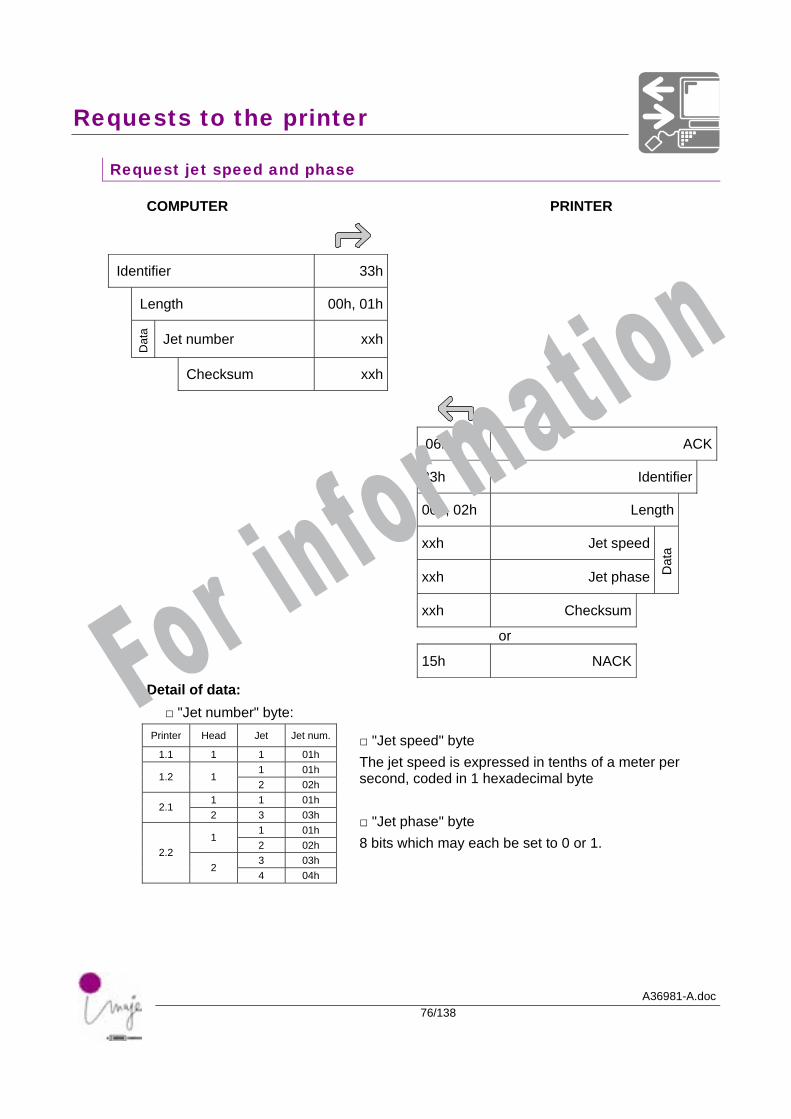
Request jet speed and phase
COMPUTER PRINTER
Identifier 33h
Length 00h, 01h
Dat
a Jet number xxh
Checksum xxh
06h ACK
33h Identifier
00h, 02h Length
xxh Jet speed
xxh Jet phase Dat
a
xxh Checksum
or
15h NACK
Detail of data: □ "Jet number" byte:
Printer Head Jet Jet num.
1.1 1 1 01h 1 01h
1.2 1 2 02h
1 1 01h 2.1
2 3 03h 1 01h
1 2 02h 3 03h
2.2 2
4 04h
□ "Jet speed" byte The jet speed is expressed in tenths of a meter per second, coded in 1 hexadecimal byte □ "Jet phase" byte 8 bits which may each be set to 0 or 1.
For information
Requests to the printer
A36981-A.doc77/138
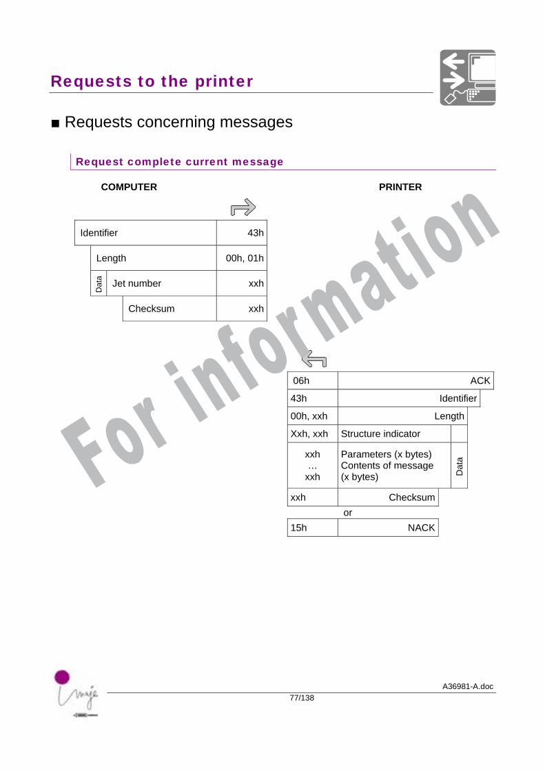
■ Requests concerning messages
Request complete current message
COMPUTER PRINTER
Identifier 43h
Length 00h, 01h
Dat
a Jet number xxh
Checksum xxh
06h ACK
43h Identifier
00h, xxh Length
Xxh, xxh Structure indicator
xxh …
xxh
Parameters (x bytes) Contents of message (x bytes) D
ata
xxh Checksum or 15h NACK
For information
Requests to the printer
A36981-A.doc78/138
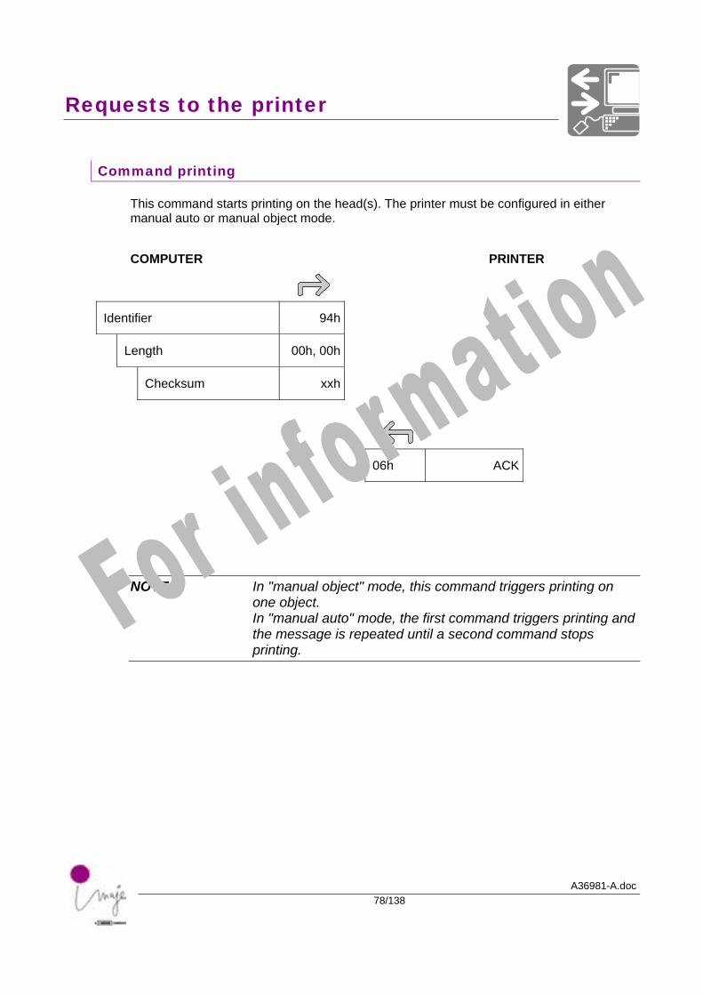
Command printing
This command starts printing on the head(s). The printer must be configured in either manual auto or manual object mode. COMPUTER PRINTER
Identifier 94h
Length 00h, 00h
Checksum xxh
06h ACK
NOTE In "manual object" mode, this command triggers printing on one object. In "manual auto" mode, the first command triggers printing and the message is repeated until a second command stops printing.
For information
Requests to the printer
A36981-A.doc79/138
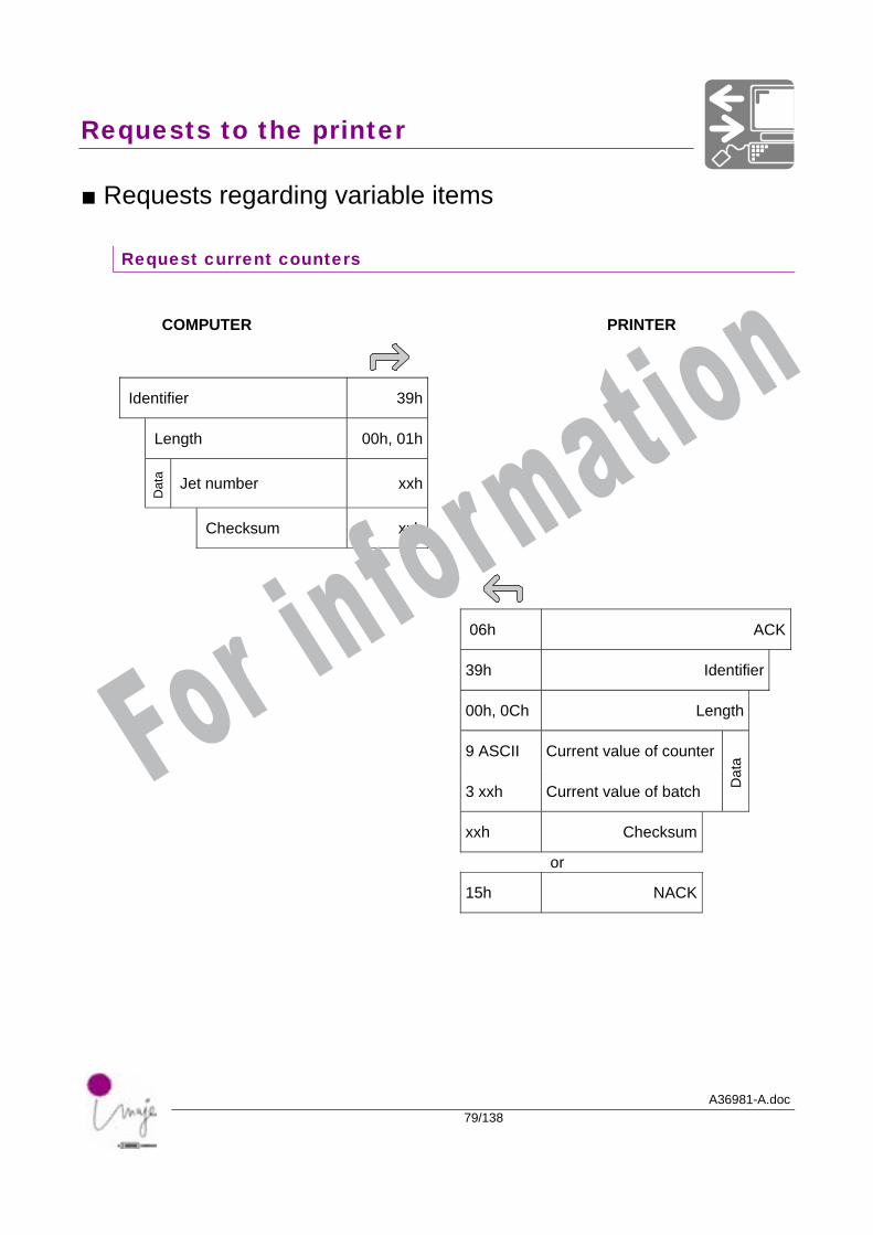
■ Requests regarding variable items
Request current counters
COMPUTER PRINTER
Identifier 39h
Length 00h, 01h
Dat
a Jet number xxh
Checksum xxh
06h ACK
39h Identifier
00h, 0Ch Length
9 ASCII Current value of counter
3 xxh Current value of batch Dat
a
xxh Checksum
or
15h NACK
For information
Requests to the printer
A36981-A.doc80/138
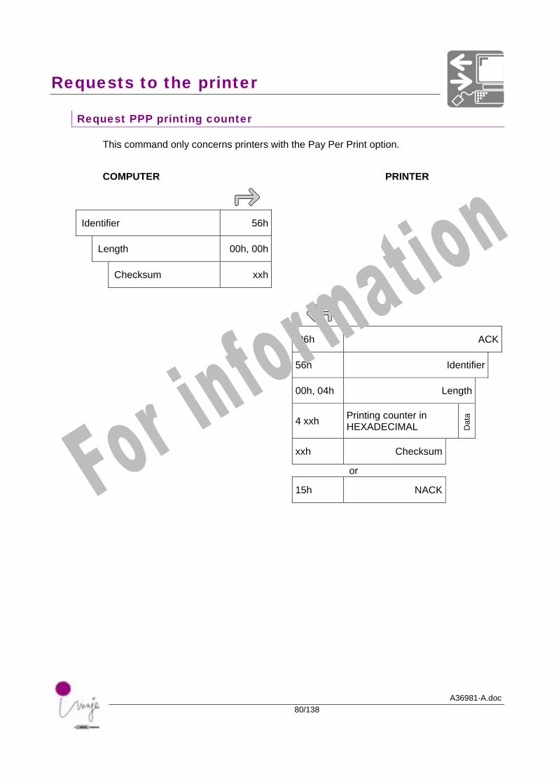
Request PPP printing counter
This command only concerns printers with the Pay Per Print option. COMPUTER PRINTER
Identifier 56h
Length 00h, 00h
Checksum xxh
06h ACK
56h Identifier
00h, 04h Length
4 xxh Printing counter in HEXADECIMAL D
ata
xxh Checksum
or
15h NACK
For information
Requests to the printer
A36981-A.doc81/138
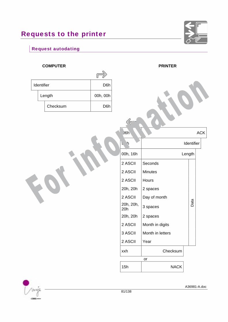
Request autodating
COMPUTER PRINTER
Identifier D6h
Length 00h, 00h
Checksum D6h
06h ACK
9Ch Identifier
00h, 16h Length
2 ASCII Seconds
2 ASCII Minutes
2 ASCII Hours
20h, 20h 2 spaces
2 ASCII Day of month
20h, 20h, 20h 3 spaces
20h, 20h 2 spaces
2 ASCII Month in digits
3 ASCII Month in letters
2 ASCII Year
Dat
a
xxh Checksum
or
15h NACK
For information
Requests to the printer
A36981-A.doc82/138
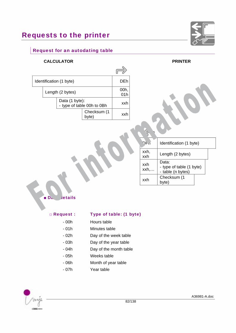
Request for an autodating table
CALCULATOR PRINTER
Identification (1 byte) DEh
Length (2 bytes) 00h, 01h
Data (1 byte): - type of table 00h to 0Bh xxh
Checksum (1 byte) xxh
DFh Identification (1 byte)
xxh, xxh Length (2 bytes)
xxh xxh,…
Data: - type of table (1 byte) - table (n bytes)
xxh Checksum (1 byte)
■ Data details
□ Request : Type of table: (1 byte)
- 00h Hours table - 01h Minutes table - 02h Day of the week table - 03h Day of the year table - 04h Day of the month table - 05h Weeks table - 06h Month of year table - 07h Year table
For information
Requests to the printer
A36981-A.doc83/138
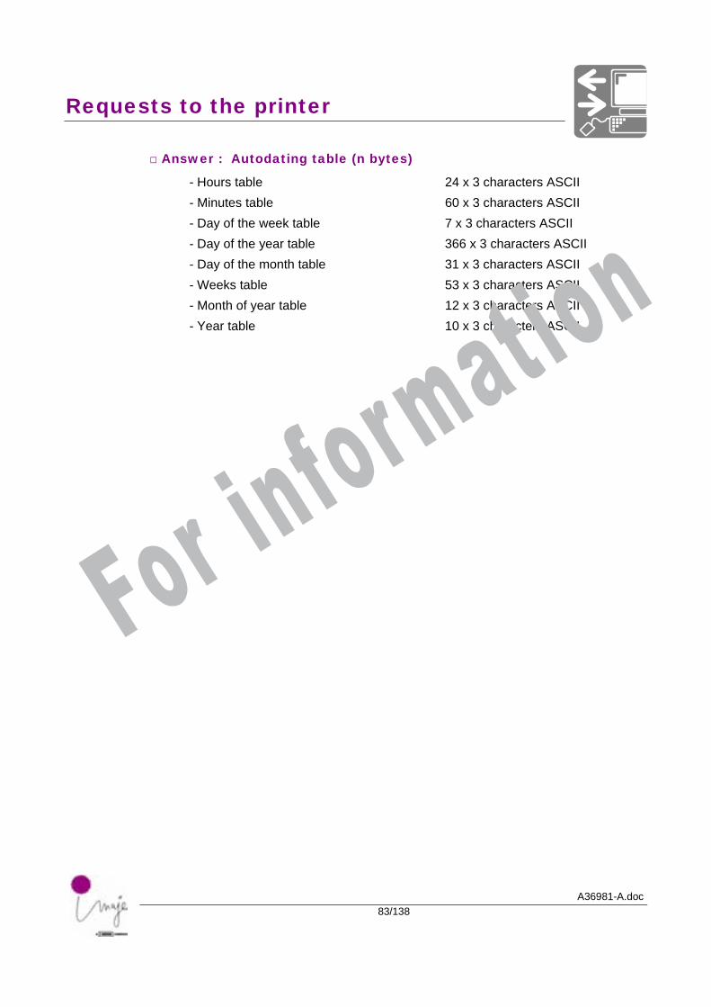
□ Answer : Autodating table (n bytes)
- Hours table 24 x 3 characters ASCII - Minutes table 60 x 3 characters ASCII - Day of the week table 7 x 3 characters ASCII - Day of the year table 366 x 3 characters ASCII - Day of the month table 31 x 3 characters ASCII - Weeks table 53 x 3 characters ASCII - Month of year table 12 x 3 characters ASCII - Year table 10 x 3 characters ASCII
For information
Requests to the printer
A36981-A.doc84/138
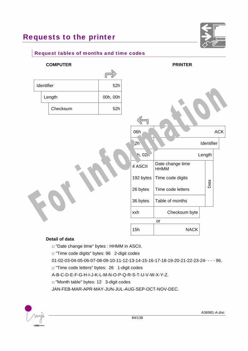
Request tables of months and time codes
COMPUTER PRINTER
Identifier 52h
Length 00h, 00h
Checksum 52h
06h ACK
52h Identifier
01h, 02h Length
4 ASCII Date change time HHMM
192 bytes Time code digits
26 bytes Time code letters
36 bytes Table of months
Dat
a
xxh Checksum byte
or
15h NACK
Detail of data □ "Date change time" bytes : HHMM in ASCII. □ "Time code digits" bytes: 96 2-digit codes 01-02-03-04-05-06-07-08-09-10-11-12-13-14-15-16-17-18-19-20-21-22-23-24- - - - 96. □ "Time code letters" bytes: 26 1-digit codes A-B-C-D-E-F-G-H-I-J-K-L-M-N-O-P-Q-R-S-T-U-V-W-X-Y-Z. □ "Month table" bytes: 12 3-digit codes JAN-FEB-MAR-APR-MAY-JUN-JUL-AUG-SEP-OCT-NOV-DEC.
For information

A36981-A.doc85/138
Details of data
For information

Details of data
A36981-A.doc86/138
For information
Details of data
A36981-A.doc87/138
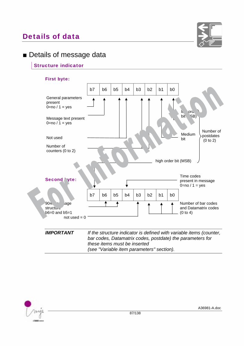
■ Details of message data Structure indicator
First byte:
b7 b6 b5 b4 b3 b2 b1 b0
General parameters present 0=no / 1 = yes
Message text present 0=no / 1 = yes
low order bit (LSB)
Not used
Medium bit
Number of postdates (0 to 2)
Number of counters (0 to 2) high order bit (MSB)
Second byte:
Time codes present in message 0=no / 1 = yes
b7 b6 b5 b4 b3 b2 b1 b0
9040 message structure b6=0 and b5=1
Number of bar codes and Datamatrix codes (0 to 4)
not used = 0
IMPORTANT If the structure indicator is defined with variable items (counter, bar codes, Datamatrix codes, postdate) the parameters for these items must be inserted (see "Variable item parameters" section).
For information
Details of data
A36981-A.doc88/138
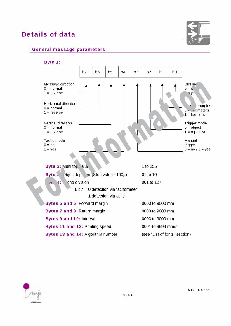
General message parameters
Byte 1:
b7 b6 b5 b4 b3 b2 b1 b0
Message direction 0 = normal 1 = reverse
DIN mode 0 = no 1 = yes
Horizontal direction 0 = normal 1 = reverse
Unit for margins0 = millimeters 1 = frame ht
Vertical direction 0 = normal 1 = reverse
Trigger mode 0 = object 1 = repetitive
Tacho mode 0 = no 1 = yes
Manual trigger 0 = no / 1 = yes
Byte 2: Multi top value 1 to 255
Byte 3: Object top filter (Step value =100µ) 01 to 10
Byte 4: Tacho division 001 to 127
Bit 7: 0 detection via tachometer 1 detection via cells
Bytes 5 and 6: Forward margin 0003 to 9000 mm
Bytes 7 and 8: Return margin 0003 to 9000 mm
Bytes 9 and 10: interval 0003 to 9000 mm
Bytes 11 and 12: Printing speed 0001 to 9999 mm/s
Bytes 13 and 14: Algorithm number. (see "List of fonts" section)
For information
Details of data
A36981-A.doc89/138
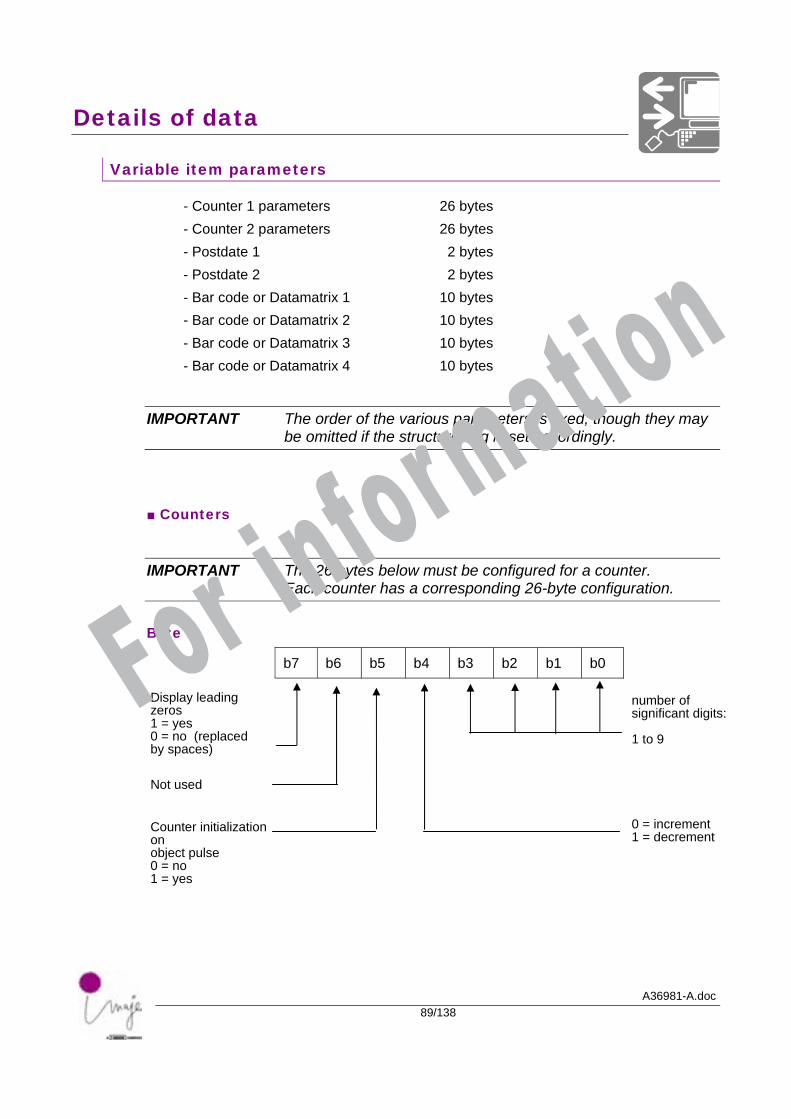
Variable item parameters
- Counter 1 parameters 26 bytes - Counter 2 parameters 26 bytes - Postdate 1 2 bytes - Postdate 2 2 bytes - Bar code or Datamatrix 1 10 bytes - Bar code or Datamatrix 2 10 bytes - Bar code or Datamatrix 3 10 bytes - Bar code or Datamatrix 4 10 bytes
IMPORTANT The order of the various parameters is fixed, though they may be omitted if the structure flag is set accordingly.
■ Counters
IMPORTANT The 26 bytes below must be configured for a counter. Each counter has a corresponding 26-byte configuration.
Byte 1:
b7 b6 b5 b4 b3 b2 b1 b0
Display leading zeros 1 = yes 0 = no (replaced by spaces)
number of significant digits: 1 to 9
Not used
0 = increment 1 = decrement
Counter initialization on object pulse 0 = no 1 = yes
For information
Details of data
A36981-A.doc90/138
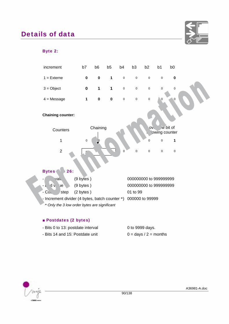
Byte 2:
increment b7 b6 b5 b4 b3 b2 b1 b0
1 = Externe 0 0 1 0 0 0 0 0
3 = Object 0 1 1 0 0 0 0 0
4 = Message 1 0 0 0 0 0 0 0
Chaining counter:
Counters Chaining overflow bit of following counter
1 0 0 0 0 0 0 0 1
2
1 0 1 0 0 0 0 0
Bytes 3 to 26:
- Start value (9 bytes ) 000000000 to 999999999 - End value (9 bytes ) 000000000 to 999999999 - Counter step (2 bytes ) 01 to 99 - Increment divider (4 bytes, batch counter *) 000000 to 99999 * Only the 3 low order bytes are significant
■ Postdates (2 bytes)
- Bits 0 to 13: postdate interval 0 to 9999 days. - Bits 14 and 15: Postdate unit 0 = days / 2 = months
For information
Details of data
A36981-A.doc91/138
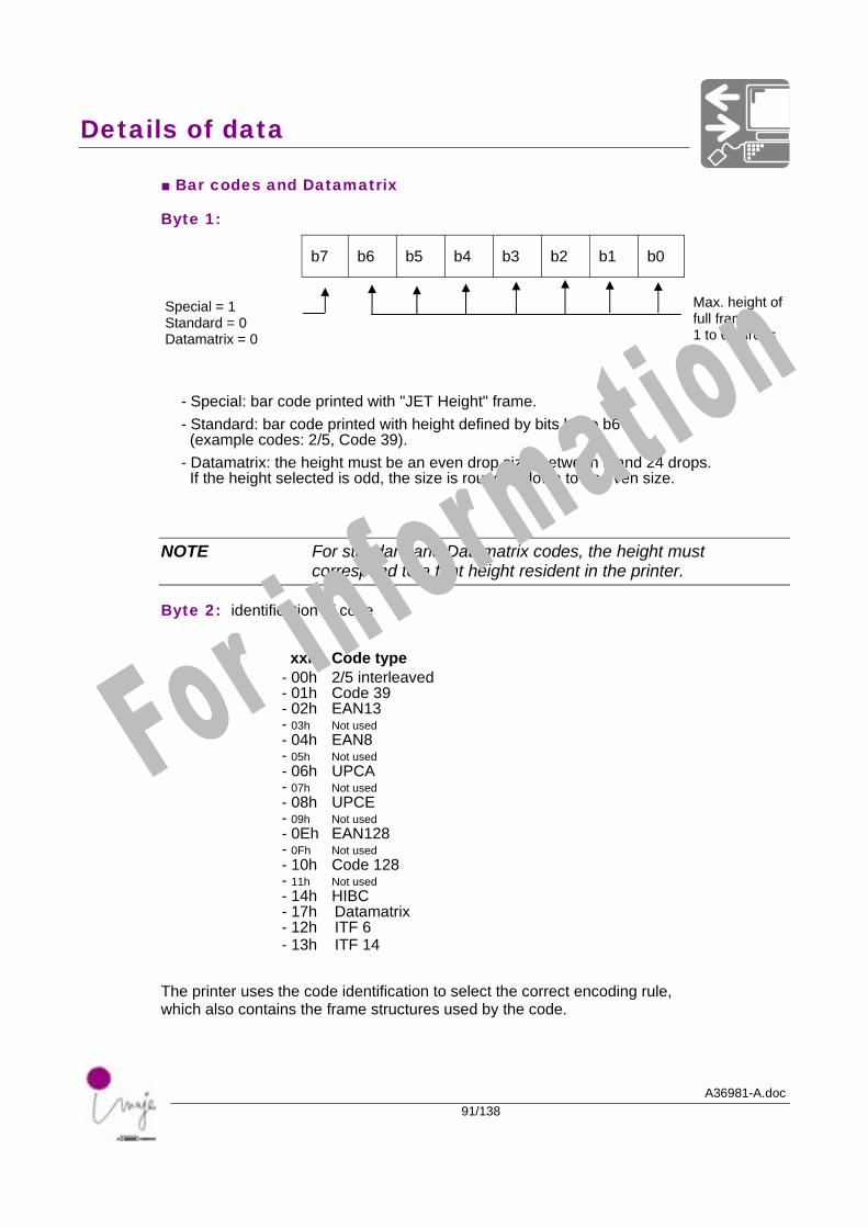
■ Bar codes and Datamatrix
Byte 1:
b7 b6 b5 b4 b3 b2 b1 b0
Special = 1 Standard = 0 Datamatrix = 0
Max. height of full frame 1 to 64 drops
- Special: bar code printed with "JET Height" frame. - Standard: bar code printed with height defined by bits b0 to b6 (example codes: 2/5, Code 39). - Datamatrix: the height must be an even drop size, between 8 and 24 drops. If the height selected is odd, the size is rounded down to an even size.
NOTE For standard and Datamatrix codes, the height must correspond to a font height resident in the printer.
Byte 2: identification of code
xxh Code type - 00h 2/5 interleaved - 01h Code 39 - 02h EAN13 - 03h Not used - 04h EAN8 - 05h Not used - 06h UPCA - 07h Not used - 08h UPCE - 09h Not used - 0Eh EAN128 - 0Fh Not used - 10h Code 128 - 11h Not used - 14h HIBC - 17h Datamatrix - 12h ITF 6 - 13h ITF 14
The printer uses the code identification to select the correct encoding rule, which also contains the frame structures used by the code.
For information
Details of data
A36981-A.doc92/138
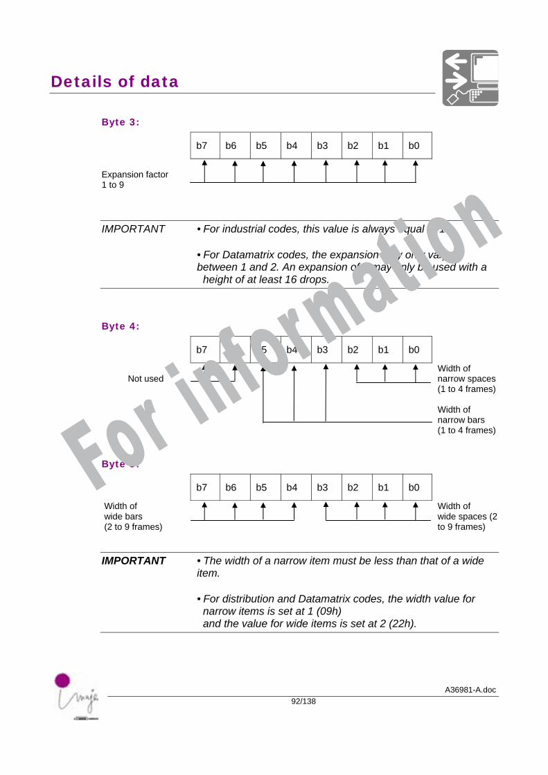
Byte 3:
b7 b6 b5 b4 b3 b2 b1 b0
Expansion factor 1 to 9
IMPORTANT • For industrial codes, this value is always equal to 1.
• For Datamatrix codes, the expansion may only vary between 1 and 2. An expansion of 2 may only be used with a height of at least 16 drops.
Byte 4:
b7 b6 b5 b4 b3 b2 b1 b0
Width of narrow spaces (1 to 4 frames)
Not used
Width of narrow bars (1 to 4 frames)
Byte 5:
b7 b6 b5 b4 b3 b2 b1 b0
Width of wide bars (2 to 9 frames)
Width of wide spaces (2 to 9 frames)
IMPORTANT • The width of a narrow item must be less than that of a wide item.
• For distribution and Datamatrix codes, the width value for narrow items is set at 1 (09h) and the value for wide items is set at 2 (22h).
For information
Details of data
A36981-A.doc93/138
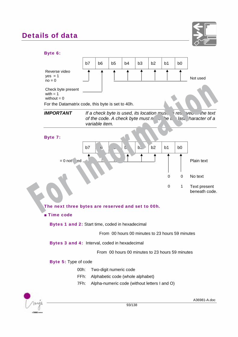
Byte 6:
b7 b6 b5 b4 b3 b2 b1 b0
Reverse video yes = 1 no = 0
Not used
Check byte present with = 1 without = 0
For the Datamatrix code, this byte is set to 40h.
IMPORTANT If a check byte is used, its location must be reserved in the text of the code. A check byte must never be the last character of a variable item.
Byte 7:
b7 b6 b5 b4 b3 b2 b1 b0
= 0 not used
Plain text
0 0 No text
0 1 Text present
beneath code.
The next three bytes are reserved and set to 00h.
■ Time code
Bytes 1 and 2: Start time, coded in hexadecimal
From 00 hours 00 minutes to 23 hours 59 minutes
Bytes 3 and 4: Interval, coded in hexadecimal
From 00 hours 00 minutes to 23 hours 59 minutes
Byte 5: Type of code
00h: Two-digit numeric code FFh: Alphabetic code (whole alphabet) 7Fh: Alpha-numeric code (without letters I and O)
For information
Details of data
A36981-A.doc94/138
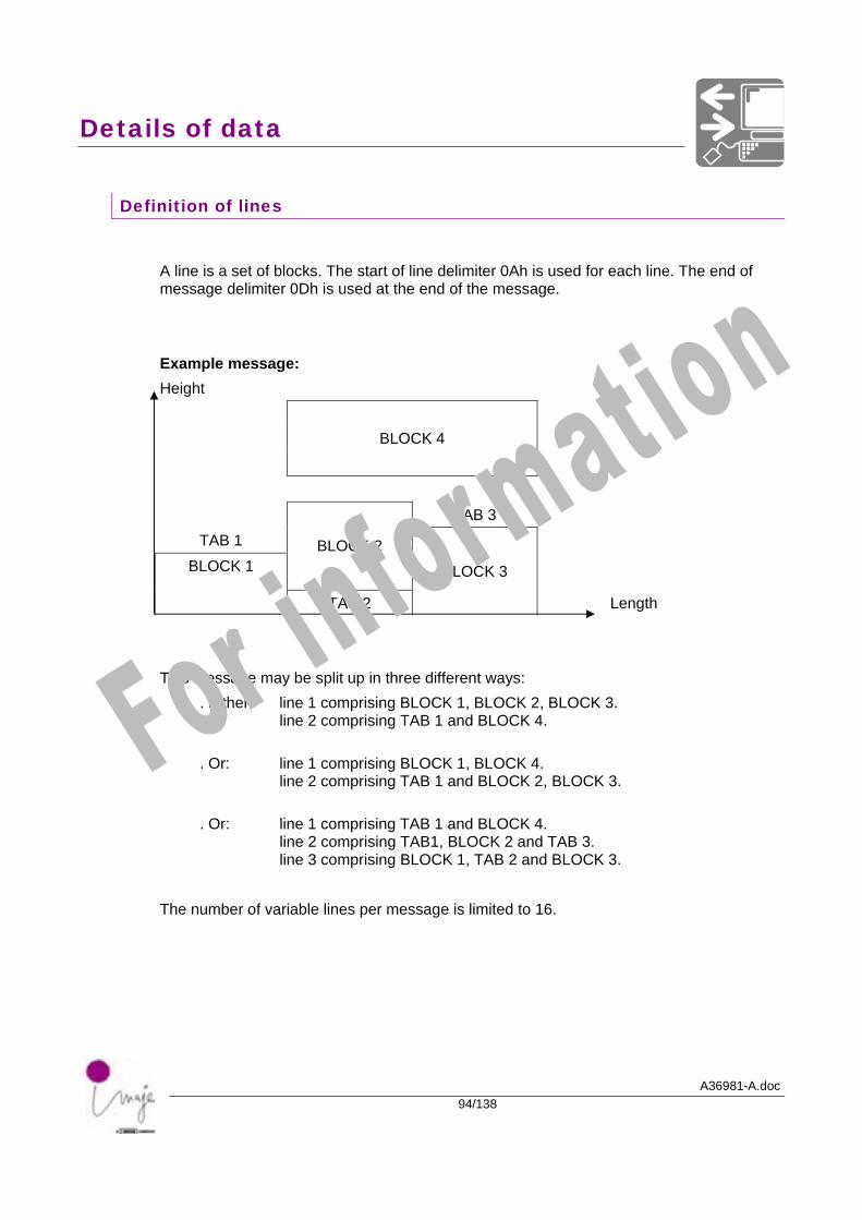
Definition of lines
A line is a set of blocks. The start of line delimiter 0Ah is used for each line. The end of message delimiter 0Dh is used at the end of the message. Example message: Height
BLOCK 4
TAB 3
TAB 1 BLOCK 2
BLOCK 1
TAB 2
BLOCK 3
Length This message may be split up in three different ways:
. Either: line 1 comprising BLOCK 1, BLOCK 2, BLOCK 3. line 2 comprising TAB 1 and BLOCK 4.
. Or: line 1 comprising BLOCK 1, BLOCK 4. line 2 comprising TAB 1 and BLOCK 2, BLOCK 3.
. Or: line 1 comprising TAB 1 and BLOCK 4. line 2 comprising TAB1, BLOCK 2 and TAB 3. line 3 comprising BLOCK 1, TAB 2 and BLOCK 3.
The number of variable lines per message is limited to 16.
For information
Details of data
A36981-A.doc95/138
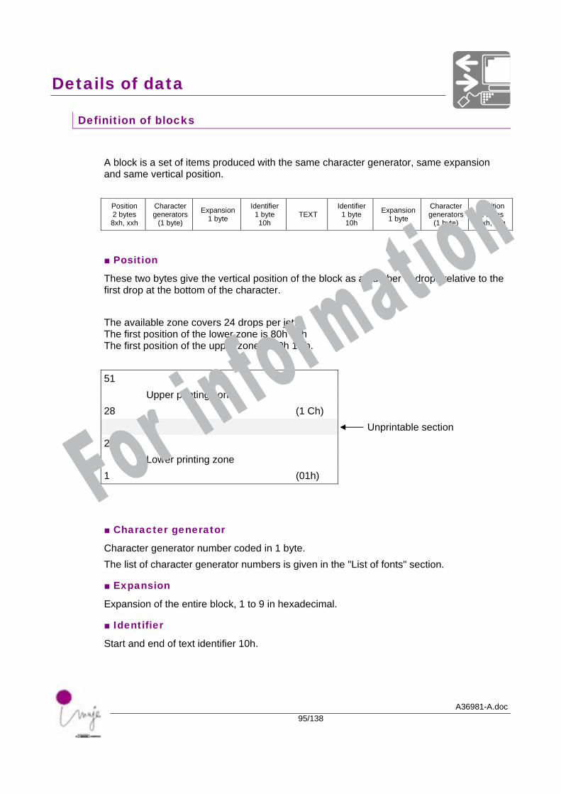
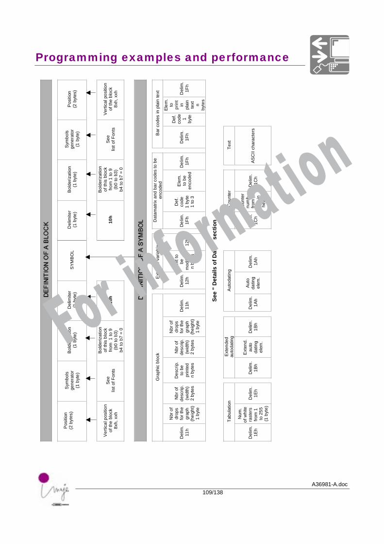
Definition of blocks
A block is a set of items produced with the same character generator, same expansion and same vertical position.
Position 2 bytes 8xh, xxh
Character generators
(1 byte)
Expansion 1 byte
Identifier1 byte 10h
TEXT Identifier
1 byte 10h
Expansion 1 byte
Character generators
(1 byte)
position2 bytes 8xh, xxh
■ Position
These two bytes give the vertical position of the block as a number of drops relative to the first drop at the bottom of the character. The available zone covers 24 drops per jet. The first position of the lower zone is 80h 01h The first position of the upper zone is 80h 1Ch. 51 Upper printing zone 28 (1 Ch) Unprintable section 24 Lower printing zone 1 (01h)
■ Character generator
Character generator number coded in 1 byte. The list of character generator numbers is given in the "List of fonts" section.
■ Expansion
Expansion of the entire block, 1 to 9 in hexadecimal.
■ Identifier
Start and end of text identifier 10h.
For information
Details of data
A36981-A.doc96/138
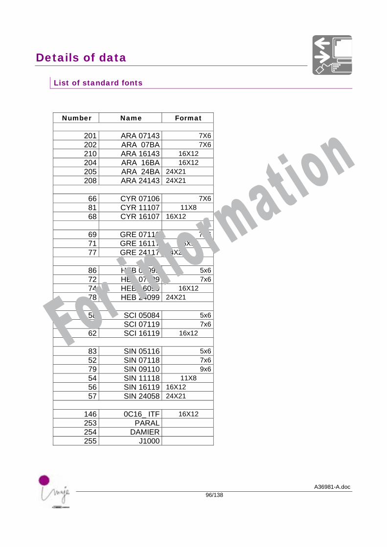
List of standard fonts
Number Name Format
201 ARA 07143 7X6202 ARA 07BA 7X6210 ARA 16143 16X12 204 ARA 16BA 16X12 205 ARA 24BA 24X21 208 ARA 24143 24X21
66 CYR 07106 7X681 CYR 11107 11X8 68 CYR 16107 16X12
69 GRE 07116 7X671 GRE 16117 16X12 77 GRE 24117 24X21
86 HEB 05099 5x672 HEB 07099 7x674 HEB 16099 16X12 78 HEB 24099 24X21
58 SCI 05084 5x660 SCI 07119 7x662 SCI 16119 16x12
83 SIN 05116 5x652 SIN 07118 7x679 SIN 09110 9x654 SIN 11118 11X8 56 SIN 16119 16X12 57 SIN 24058 24X21
146 0C16_ ITF 16X12 253 PARAL 254 DAMIER 255 J1000
For information
Details of data
A36981-A.doc97/138
Detail of text
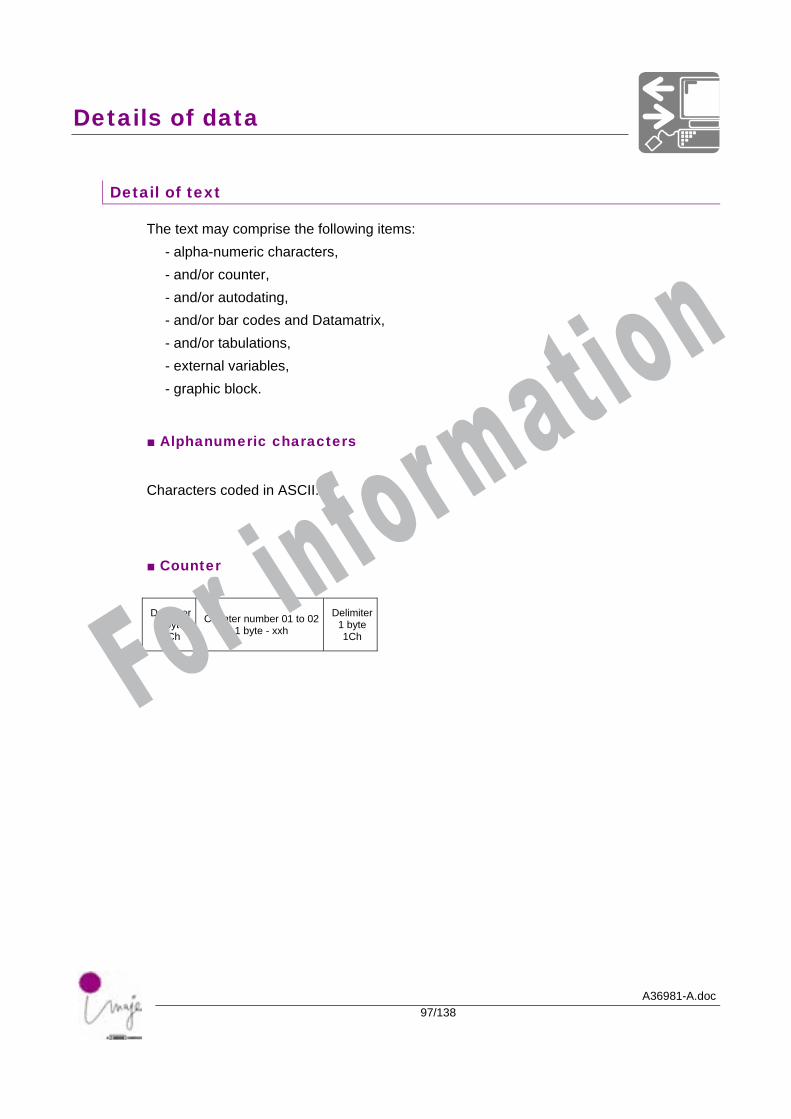
The text may comprise the following items: - alpha-numeric characters, - and/or counter, - and/or autodating, - and/or bar codes and Datamatrix, - and/or tabulations, - external variables, - graphic block.
■ Alphanumeric characters
Characters coded in ASCII.
■ Counter
Delimiter 1 byte 1Ch
Counter number 01 to 02 1 byte - xxh
Delimiter1 byte1Ch
For information
Details of data
A36981-A.doc98/138
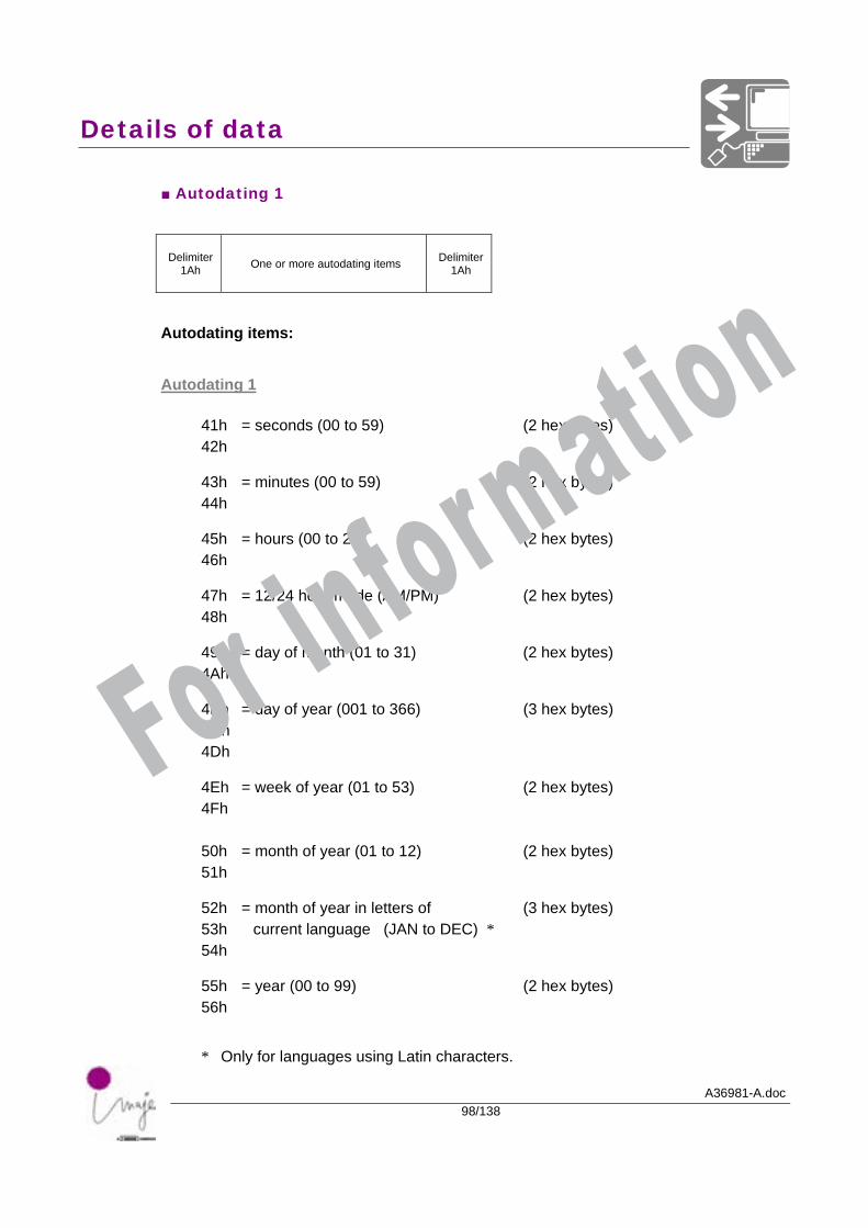
■ Autodating 1
Delimiter 1Ah One or more autodating items Delimiter
1Ah
Autodating items:
Autodating 1
41h = seconds (00 to 59) (2 hex bytes) 42h 43h = minutes (00 to 59) (2 hex bytes) 44h 45h = hours (00 to 23) (2 hex bytes) 46h 47h = 12/24 hour mode (AM/PM) (2 hex bytes) 48h 49h = day of month (01 to 31) (2 hex bytes) 4Ah 4Bh = day of year (001 to 366) (3 hex bytes) 4Ch 4Dh 4Eh = week of year (01 to 53) (2 hex bytes) 4Fh 50h = month of year (01 to 12) (2 hex bytes) 51h 52h = month of year in letters of (3 hex bytes) 53h current language (JAN to DEC) * 54h 55h = year (00 to 99) (2 hex bytes) 56h
* Only for languages using Latin characters.
For information
Details of data
A36981-A.doc99/138
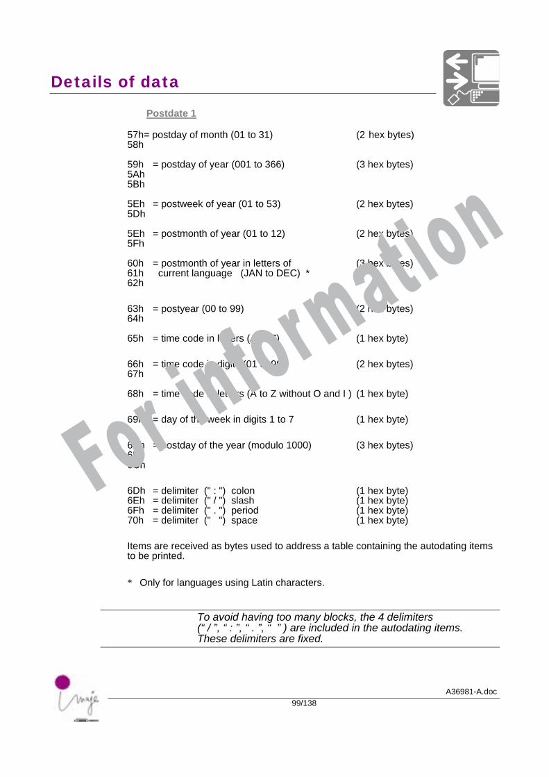
Postdate 1 57h= postday of month (01 to 31) (2 hex bytes) 58h 59h = postday of year (001 to 366) (3 hex bytes) 5Ah 5Bh 5Eh = postweek of year (01 to 53) (2 hex bytes) 5Dh 5Eh = postmonth of year (01 to 12) (2 hex bytes) 5Fh 60h = postmonth of year in letters of (3 hex bytes) 61h current language (JAN to DEC) * 62h
63h = postyear (00 to 99) (2 hex bytes) 64h 65h = time code in letters (A to Z) (1 hex byte)
66h = time code in digits (01 to 99) (2 hex bytes) 67h 68h = time code in letters (A to Z without O and I ) (1 hex byte)
69h = day of the week in digits 1 to 7 (1 hex byte)
6Ah = postday of the year (modulo 1000) (3 hex bytes) 6Bh 6Ch
6Dh = delimiter (" : ") colon (1 hex byte) 6Eh = delimiter (" / ") slash (1 hex byte) 6Fh = delimiter (" . ") period (1 hex byte) 70h = delimiter (" ") space (1 hex byte)
Items are received as bytes used to address a table containing the autodating items to be printed.
* Only for languages using Latin characters.
To avoid having too many blocks, the 4 delimiters (“ / ”, “ : ”, “ . ”, “ ” ) are included in the autodating items. These delimiters are fixed.
For information
Details of data
A36981-A.doc100/138
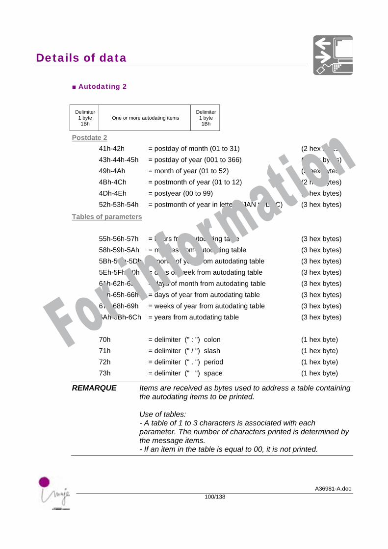
■ Autodating 2
Delimiter 1 byte 1Bh
One or more autodating items Delimiter
1 byte 1Bh
Postdate 2 41h-42h = postday of month (01 to 31) (2 hex bytes) 43h-44h-45h = postday of year (001 to 366) (3 hex bytes) 49h-4Ah = month of year (01 to 52) (2 hex bytes) 4Bh-4Ch = postmonth of year (01 to 12) (2 hex bytes) 4Dh-4Eh = postyear (00 to 99) (2 hex bytes) 52h-53h-54h = postmonth of year in letters (JAN to DEC) (3 hex bytes)
Tables of parameters
55h-56h-57h = hours from autodating table (3 hex bytes) 58h-59h-5Ah = minutes from autodating table (3 hex bytes) 5Bh-5Ch-5Dh = month of year from autodating table (3 hex bytes) 5Eh-5Fh-60h = days of week from autodating table (3 hex bytes) 61h-62h-63h = days of month from autodating table (3 hex bytes) 64h-65h-66h = days of year from autodating table (3 hex bytes) 67h-68h-69h = weeks of year from autodating table (3 hex bytes) 6Ah-6Bh-6Ch = years from autodating table (3 hex bytes) 70h = delimiter (" : ") colon (1 hex byte) 71h = delimiter (" / ") slash (1 hex byte) 72h = delimiter (" . ") period (1 hex byte) 73h = delimiter (" ") space (1 hex byte)
REMARQUE Items are received as bytes used to address a table containing the autodating items to be printed. Use of tables: - A table of 1 to 3 characters is associated with each parameter. The number of characters printed is determined by the message items. - If an item in the table is equal to 00, it is not printed.
For information
Details of data
A36981-A.doc101/138
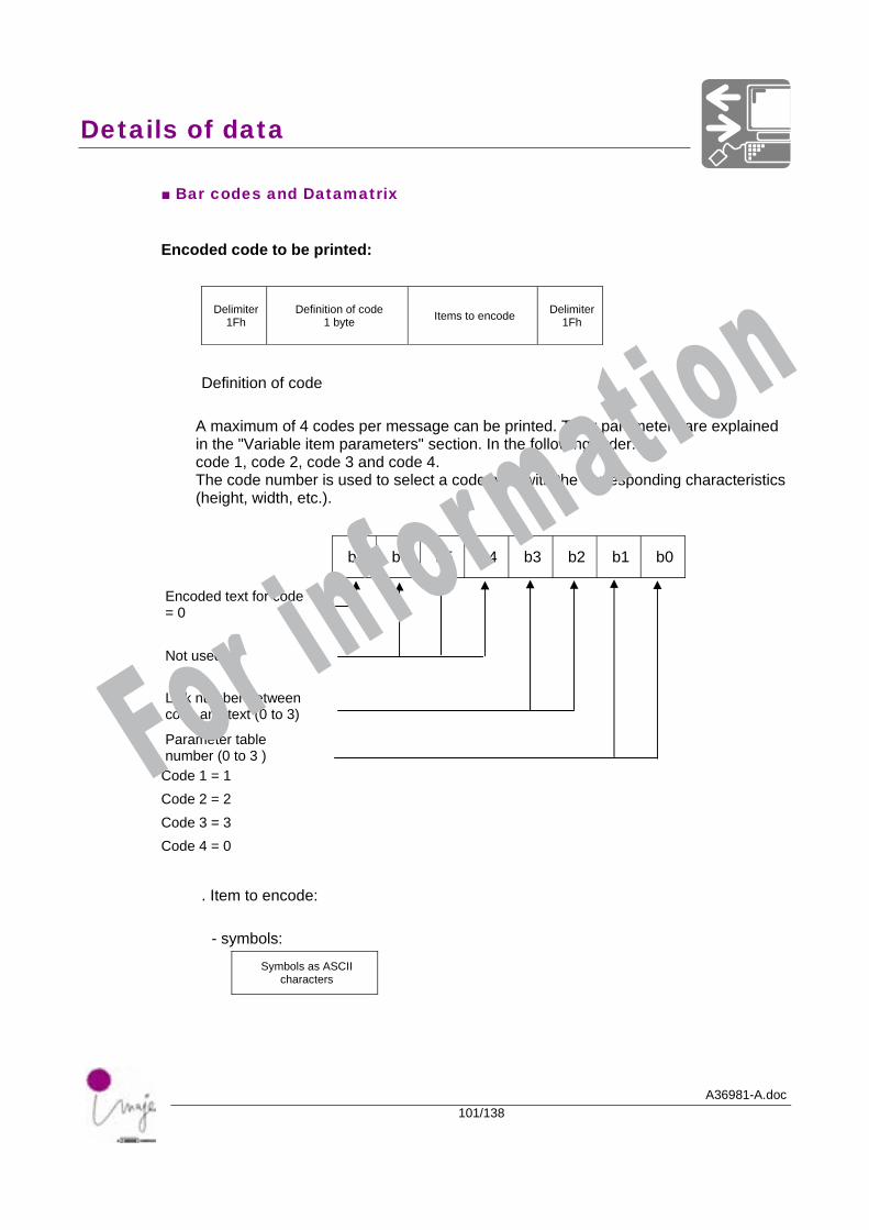
■ Bar codes and Datamatrix
Encoded code to be printed:
Delimiter1Fh
Definition of code 1 byte Items to encode Delimiter
1Fh
Definition of code
A maximum of 4 codes per message can be printed. Their parameters are explained in the "Variable item parameters" section. In the following order: code 1, code 2, code 3 and code 4. The code number is used to select a code type with the corresponding characteristics (height, width, etc.).
b7 b6 b5 b4 b3 b2 b1 b0
Encoded text for code = 0
Not used
Link number between code and text (0 to 3)
Parameter table number (0 to 3 )
Code 1 = 1 Code 2 = 2 Code 3 = 3 Code 4 = 0
. Item to encode:
- symbols:
Symbols as ASCII characters
For information
Details of data
A36981-A.doc102/138
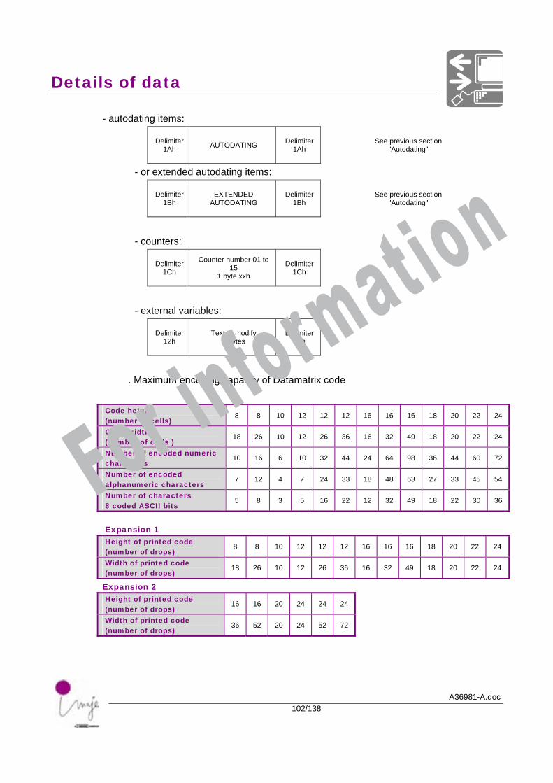
- autodating items:
Delimiter 1Ah AUTODATING Delimiter
1Ah See previous section
"Autodating"
- or extended autodating items:
Delimiter 1Bh
EXTENDED AUTODATING
Delimiter 1Bh
See previous section "Autodating"
- counters:
Delimiter 1Ch
Counter number 01 to 15
1 byte xxh
Delimiter 1Ch
- external variables:
Delimiter 12h
Text to modify n bytes
Delimiter 12h
. Maximum encoding capacity of Datamatrix code
Code height (number of cells)
8 8 10 12 12 12 16 16 16 18 20 22 24
Code width (number of cells )
18 26 10 12 26 36 16 32 49 18 20 22 24
Number of encoded numeric characters
10 16 6 10 32 44 24 64 98 36 44 60 72
Number of encoded alphanumeric characters
7 12 4 7 24 33 18 48 63 27 33 45 54
Number of characters 8 coded ASCII bits
5 8 3 5 16 22 12 32 49 18 22 30 36
Expansion 1 Height of printed code (number of drops)
8 8 10 12 12 12 16 16 16 18 20 22 24
Width of printed code (number of drops)
18 26 10 12 26 36 16 32 49 18 20 22 24
Expansion 2 Height of printed code (number of drops)
16 16 20 24 24 24
Width of printed code (number of drops)
36 52 20 24 52 72
For information
Details of data
A36981-A.doc103/138
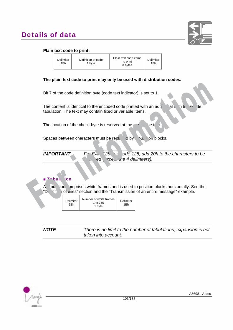
Plain text code to print:
Delimiter1Fh
Definition of code 1 byte
Plain text code items to print n bytes
Delimiter 1Fh
The plain text code to print may only be used with distribution codes. Bit 7 of the code definition byte (code text indicator) is set to 1. The content is identical to the encoded code printed with an additional item to encode: tabulation. The text may contain fixed or variable items. The location of the check byte is reserved at the end of the text. Spaces between characters must be replaced by tabulation blocks.
IMPORTANT For EAN 128 and code 128, add 20h to the characters to be encoded (except the 4 delimiters).
■ Tabulation
A tabulation comprises white frames and is used to position blocks horizontally. See the "Definition of lines" section and the "Transmission of an entire message" example.
Delimiter 1Eh
Number of white frames 1 to 255 1 byte
Delimiter 1Eh
NOTE There is no limit to the number of tabulations; expansion is not taken into account.
For information
Details of data
A36981-A.doc104/138
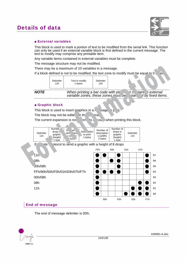
■ External variables This block is used to mark a portion of text to be modified from the serial link. This function can only be used if an external variable block is first defined in the current message. The text to modify may comprise any printable item. Any variable items contained in external variables must be complete. The message structure may not be modified. There may be a maximum of 10 variables in a message. If a block defined is not to be modified, the text zone to modify must be equal to 0 bytes.
Delimiter 12h
Text to modify n bytes
Delimiter 12h
NOTE When printing a bar code with plain text containing external variable zones, these zones must be separated by fixed items.
■ Graphic block This block is used to insert graphics in a message to print. The block may not be edited on the terminal. The current expansion is not taken into account when printing this block.
Delimiter 11h
Number of drops in graphic (height) 1 byte
Number of descriptions (width) 2 bytes
Description to print n bytes
Number of descriptions (width)2 bytes
Number of drops in graphic (height) 1 byte
Delimiter 11h
Example: Protocol to send a graphic with a height of 8 drops FFh 50h 01h 07h
11h B7
08h B6
00h/08h B5
FFh/90h/50h/F0h/01h/03h/07h/F7h B4
00h/08h B3
08h B2
11h B1
B0
90h F0h 03h F7h
End of message
The end of message delimiter is 0Dh.
For information

A36981-A.doc105/138
Programming examples
and performance
For information

Programming examples and performance
A36981-A.doc106/138
For information
Programming examples and performance
A36981-A.doc107/138
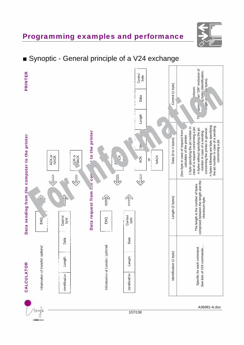
■ Synoptic - General principle of a V24 exchange
PR
INT
ER
Con
trol (
1 by
te)
Che
cksu
m.
This
repr
esen
t an
"OR
" exc
lusi
ve o
f al
l pre
cedi
ng b
ytes
(ide
ntifi
catio
n,
leng
th a
nd d
ata
byte
s).
Dat
a (0
to n
byt
es)
Zero
byt
e in
cas
e of
requ
est f
rom
the
calc
ulat
or o
f the
prin
ter.
1 by
te s
peci
fyin
g th
e je
t num
ber i
n ca
se o
f a re
ques
t con
cern
ing
a je
t. n
byte
s w
ithou
t spe
cify
ing
the
jet
num
ber i
n ca
se o
f a s
endi
ng
conc
erni
ng th
e pr
inte
r in
gene
ral.
n by
tes
follo
win
g ar
e by
te s
peci
fyin
g th
e je
t num
ber i
n ca
se o
f a s
endi
ng
conc
erni
ng a
jet.
Dat
a se
ndin
g fr
om t
he c
ompu
ter
to t
he p
rint
er
Leng
th (2
byt
es)
The
leng
th is
the
num
ber o
f byt
es
com
pris
ed b
etw
een
the
leng
th a
nd th
e ch
ecks
um b
yte.
CA
LCU
LAT
OR
Dat
a re
ques
t fr
om t
he c
ompu
ter
to t
he p
rint
er
Iden
tific
atio
n (1
byt
e)
Spec
ific
for e
ach
com
man
d.
See
list
s of
V24
com
man
ds…
For information
Programming examples and performance
A36981-A.doc108/138
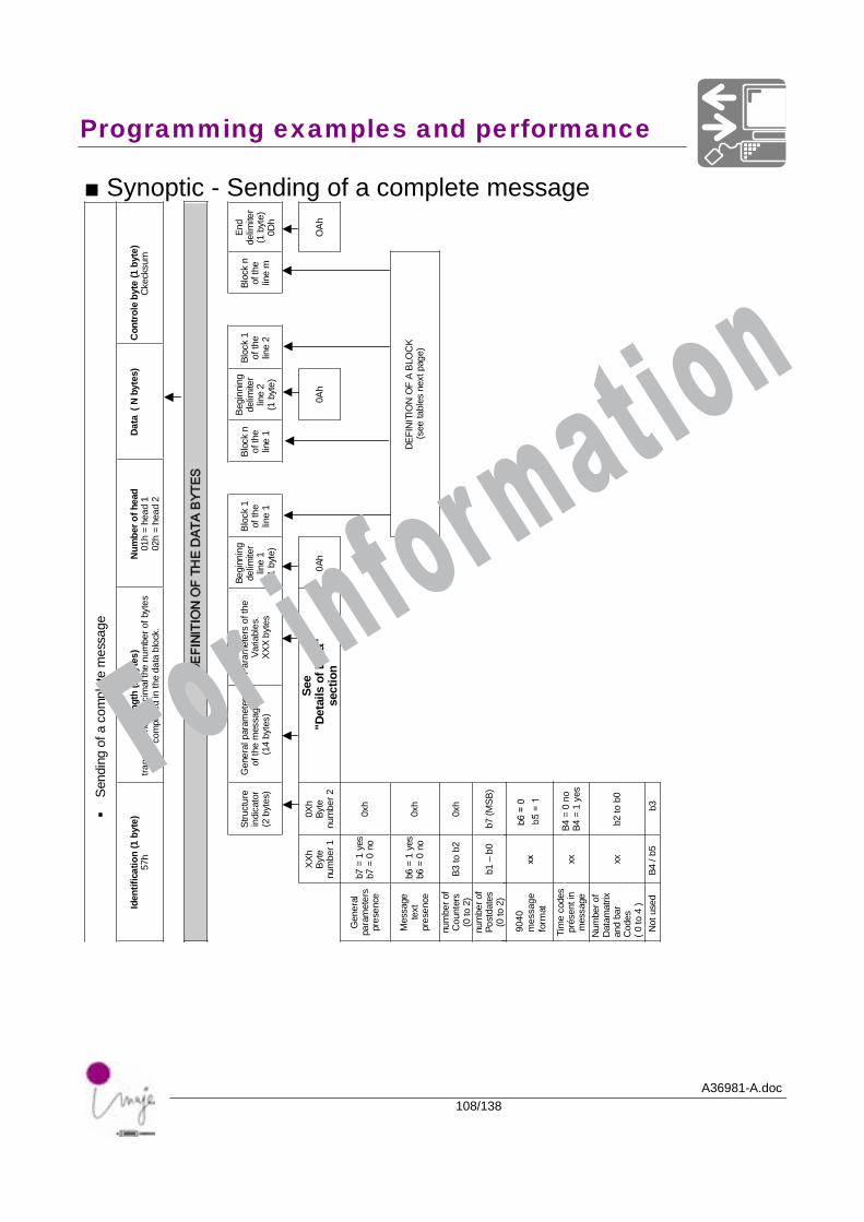
■ Synoptic - Sending of a complete message
egassem
etelpmoc
afognidneS
)etyb1(
noitacifitnedIh75
)setyb2(
htgneLsetybforeb
munehtla
micedaxehnirefsnart
.kcolbatad
ehtni
desirpmoc
daehforebmu
N1
daeh=
h102
daeh=
h20
)setybN(
ataD)etyb
1(etyb
elortnoC
muskcekC
SETYBATA
DE
HTF
ON
OITINIFE
D
erutcurtSrotacidni)setyb
2(
sretemaraplarene
Gegasse
mehtfo
)setyb41(
ehtfosrete
maraP.selbairaVsetyb
XXX
gninnigeBreti
miled1
enil)etyb
1(
1kcolBehtfo1
enil
nkcolBehtfo1
enil
gninnigeBreti
miled2
enil)etyb
1(
1kcolBehtfo2
enil
nkcolBehtfom
enil
dnEreti
miled)etyb
1(h
D0
hXXetyB
1rebmun
hX0etyB
2rebmun
eeS"ata
DfosliateD"
noitceshA
OhA0
hA0
lareneG
sretemarap
ecneserpsey
1=
7bon
0=
7bhx0
egasseM
txetecneserp
sey1
=6b
on0
=6b
hx0K
COLB
AF
ON
OITINIFED
)egaptxenselbat
ees(
forebmun
sretnuoC
)2ot
0(hx0
2bot
3B
forebmun
setadtsoP)2
ot0(
)BSM(
7b0b
–1b
sedoce
miTnitnesérpegasse
mxx
on0
=4B
sey1
=4B
forebmu
Nxirta
mataD
rabdna
sedoC
)4
ot0(
0bot
2bxx
3b5b/
4Bdesuto
N9040
mes
sage
form
at
For information
Programming examples and performance
A36981-A.doc109/138
KC
OLB
AF
ON
OITINIFE
D
noitisoP
)se tyb2 (
slobmy
Srotareneg
)etyb1(
noitaziredloB
)etyb1(
retimile
D)etyb
1(L
OB
MYS
retimile
D)etyb
1(noitaziredlo
B)etyb
1(
slobmy
Srotareneg
)etyb1(
noitisoP
)setyb2(
noitisoplacitreV
kcolbehtfo
hxx,hx8
eeSstnoFfotsil
noitaziredloB
kcolbsihtfo
9ot
1morf
)3bot
0b(0
=7b
ot4b
h01h01
noitaziredloB
kcolbsihtfo
9ot
1morf
)3bot
0b(0
=7b
ot4b
eeSstnoFfotsil
noitisoplacitreV
kcolbehtfo
hxx,hx8
LO
BMY
SA
FO
NOITI
NIFE
D
kcolbcihpar
Gselbairavlanretx
Eeb
otsedocrab
dnaxirta
mataD
dedocnetxet
nialpni
sedocraB
.mile
Dh11
forbN
spordehtrofhparg
)thgieh(etyb
1
forbN
.pircsed)htdi
w(setyb
2
.pircseD
ebot
detnirpsetyb
n
forbN
.pircsed)htdi
w(setyb
2
forbN
spordehtrofhparg
)thgieh(etyb
1
.mile
Dh11
.mile
Dh21
ottxeTeb
deifidom
setybn
.mile
Dh21
.mile
DhF1
.feD
edocetyb
13
ot1
.mel
Eeb
otdedocne
.mile
DhF1
.mile
DhF1
.feD
edoc1 etyb
.melE
ottnirp
ninialptxet nsetyb
.mile
DhF1
noitces"ata
Dfosliate
D"
eeS
noitalubaTdednetxEgnitadotua
gnitadotuA
txeTretnuo
C
.mile
DhE1
.mu
Netih
wfosretsar1
morf552
ot)etyb
1(
.mile
DhE1
.mile
DhB1
.dnetxE
otuagnitad.
mele
.mile
DhB1
.mile
DhA 1
otuA
gnitad.
mele
.mile
DhA1
.mile
Dh
C1
retnuoC
.bmun
1morf
ni2
ot.axeh
.mile
Dh
C1sretcarahcII
CSA
For information
Programming examples and performance
A36981-A.doc110/138
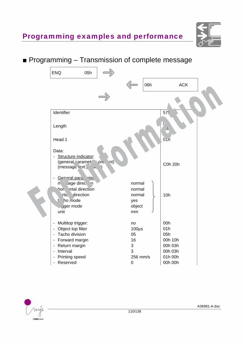
■ Programming – Transmission of complete message
ENQ 05h
06h ACK
Identifier 57h
Length 00h 63h
Head 1 01h Data: - Structure indicator: (general parameters present) (message text present) C0h 20h
- General parameters: message direction normal horizontal direction normal vertical direction normal 10h tacho mode yes trigger mode object unit mm - Multitop trigger: no 00h - Object top filter 100µs 01h - Tacho division 05 05h - Forward margin 16 00h 10h - Return margin 3 00h 03h - Interval 3 00h 03h - Printing speed 256 mm/s 01h 00h - Reserved 0 00h 00h
For information
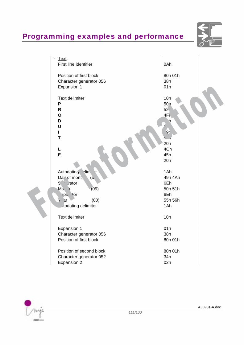
Programming examples and performance
A36981-A.doc111/138
- Text: First line identifier 0Ah Position of first block 80h 01h Character generator 056 38h Expansion 1 01h Text delimiter 10h P 50h R 52h O 4Fh D 44h U 55h I 49h T 54h 20h L 4Ch E 45h 20h Autodating delimiter 1Ah Day of month (30) 49h 4Ah Separator 6Eh Month (09) 50h 51h Separator 6Eh Year (00) 55h 56h Autodating delimiter 1Ah Text delimiter 10h Expansion 1 01h Character generator 056 38h Position of first block 80h 01h Position of second block 80h 01h Character generator 052 34h Expansion 2 02h
For information
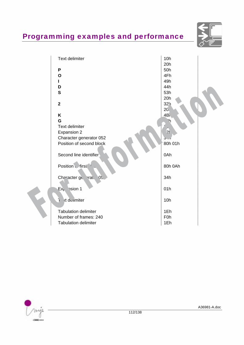
Programming examples and performance
A36981-A.doc112/138
Text delimiter 10h 20h P 50h O 4Fh I 49h D 44h S 53h 20h 2 32h 20h K 4Bh G 47h Text delimiter 10h Expansion 2 02h Character generator 052 34h Position of second block 80h 01h Second line identifier 0Ah Position of first block 80h 0Ah Character generator 052 34h Expansion 1 01h Text delimiter 10h Tabulation delimiter 1Eh Number of frames: 240 F0h Tabulation delimiter 1Eh
For information
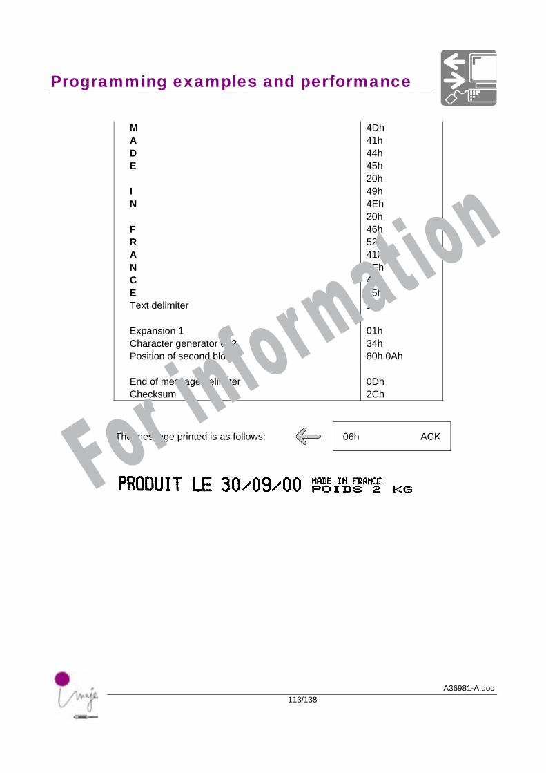
Programming examples and performance
A36981-A.doc113/138
M 4Dh A 41h D 44h E 45h 20h I 49h N 4Eh 20h F 46h R 52h A 41h N 4Eh C 43h E 45h Text delimiter 10h Expansion 1 01h Character generator 052 34h Position of second block 80h 0Ah End of message delimiter 0Dh Checksum 2Ch
The message printed is as follows: 06h ACK
For information
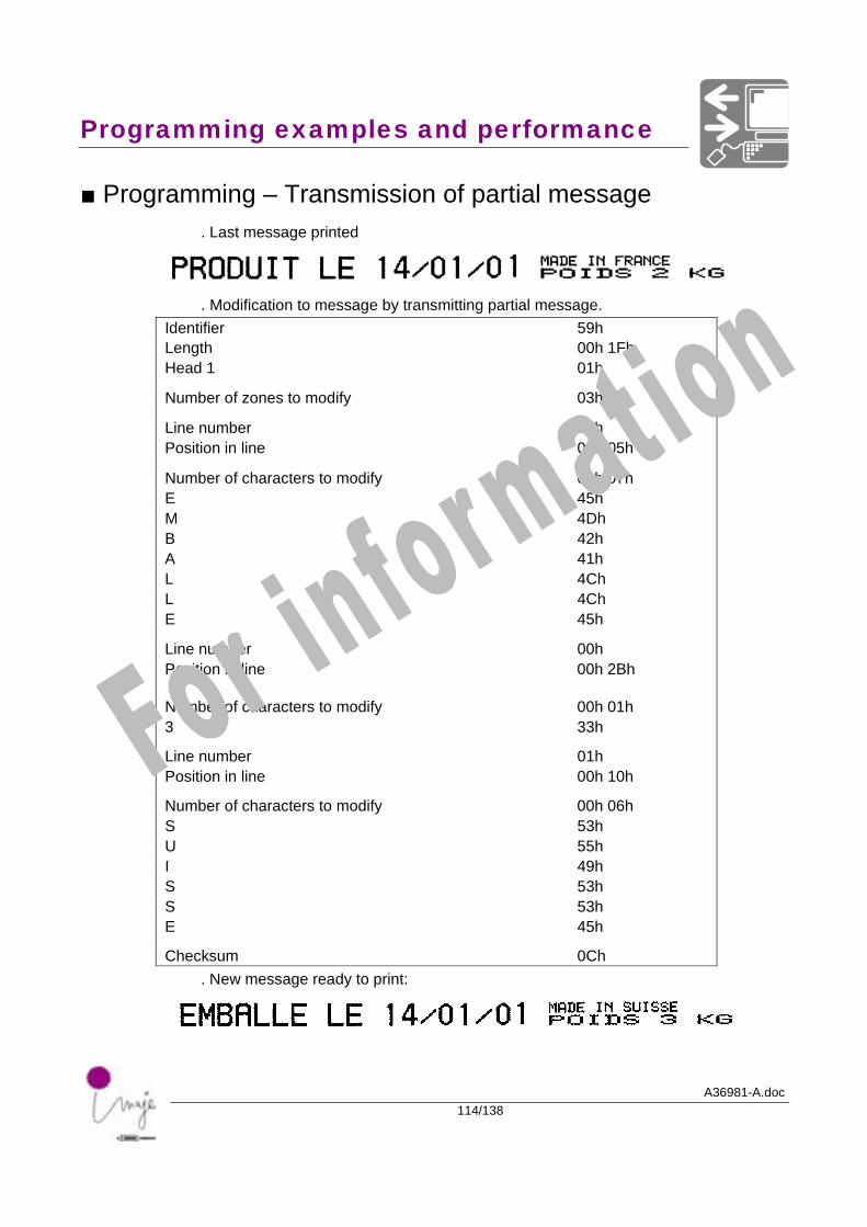
Programming examples and performance
A36981-A.doc114/138
■ Programming – Transmission of partial message . Last message printed
. Modification to message by transmitting partial message.
Identifier 59h Length 00h 1Fh Head 1 01h
Number of zones to modify 03h
Line number 00h Position in line 00h 05h
Number of characters to modify 00h 07h E 45h M 4Dh B 42h A 41h L 4Ch L 4Ch E 45h
Line number 00h Position in line 00h 2Bh Number of characters to modify 00h 01h 3 33h
Line number 01h Position in line 00h 10h
Number of characters to modify 00h 06h S 53h U 55h I 49h S 53h S 53h E 45h
Checksum 0Ch . New message ready to print:
For information
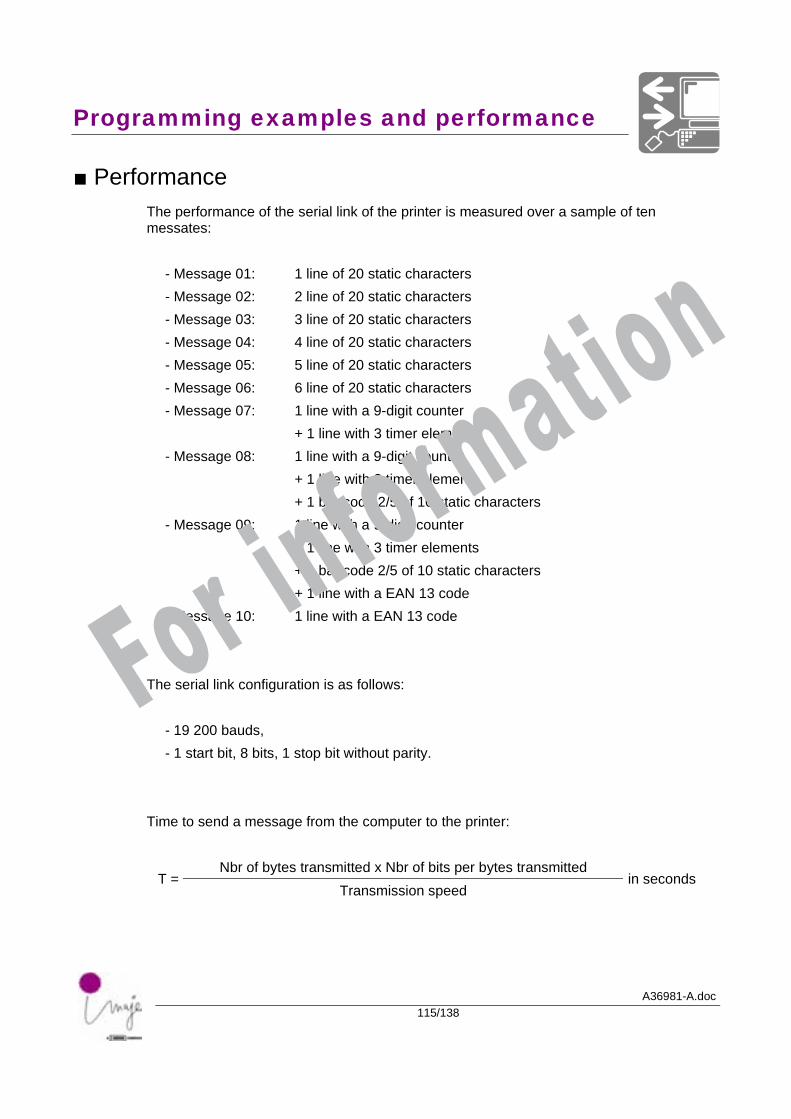
Programming examples and performance
A36981-A.doc115/138
■ Performance The performance of the serial link of the printer is measured over a sample of ten messates:
- Message 01: 1 line of 20 static characters - Message 02: 2 line of 20 static characters - Message 03: 3 line of 20 static characters - Message 04: 4 line of 20 static characters - Message 05: 5 line of 20 static characters - Message 06: 6 line of 20 static characters - Message 07: 1 line with a 9-digit counter
+ 1 line with 3 timer elements - Message 08: 1 line with a 9-digit counter
+ 1 line with 3 timer elements + 1 bar code 2/5 of 10 static characters
- Message 09: 1 line with a 9-digit counter + 1 line with 3 timer elements + 1 bar code 2/5 of 10 static characters + 1 line with a EAN 13 code
- Message 10: 1 line with a EAN 13 code The serial link configuration is as follows:
- 19 200 bauds, - 1 start bit, 8 bits, 1 stop bit without parity.
Time to send a message from the computer to the printer:
Nbr of bytes transmitted x Nbr of bits per bytes transmitted T =
Transmission speed in seconds
For information
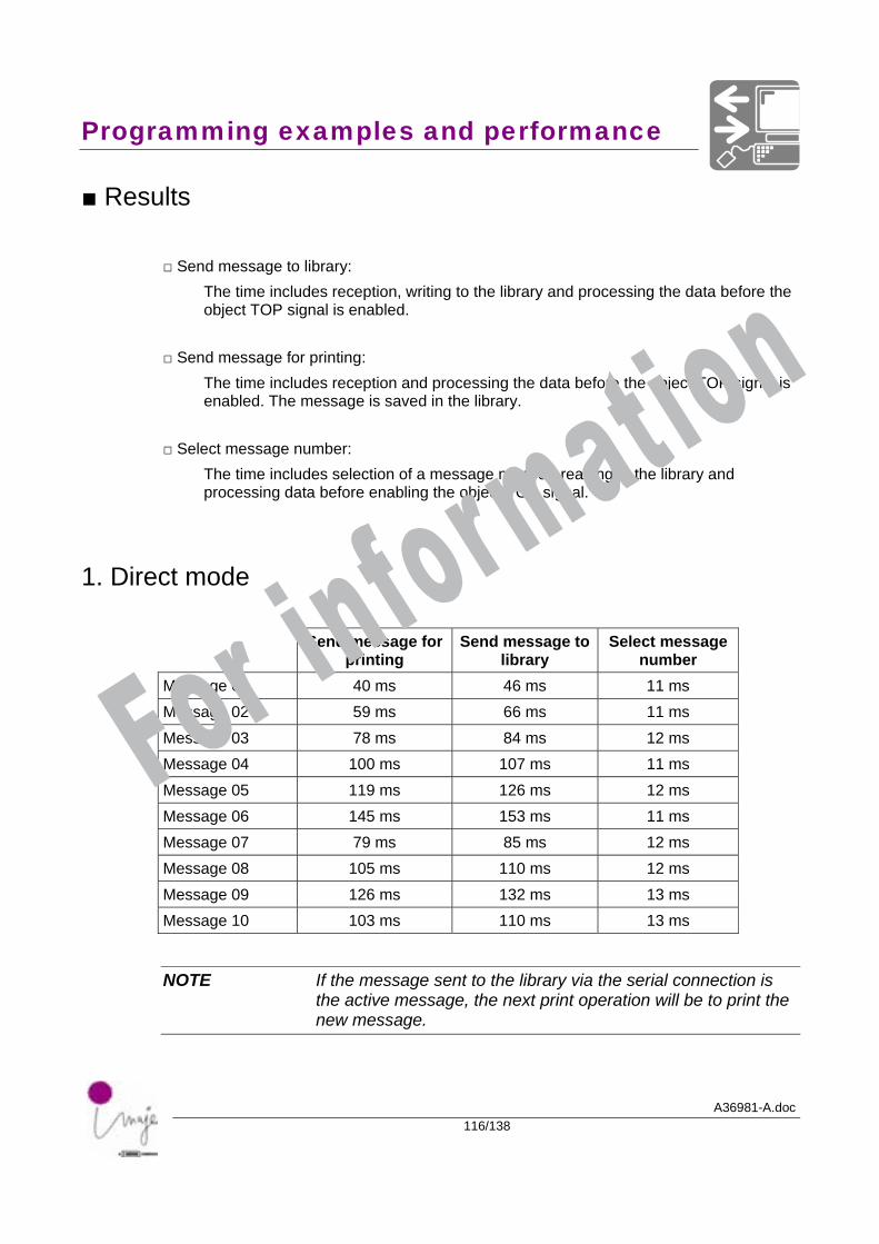
Programming examples and performance
A36981-A.doc116/138
■ Results
□ Send message to library: The time includes reception, writing to the library and processing the data before the object TOP signal is enabled.
□ Send message for printing: The time includes reception and processing the data before the object TOP signal is enabled. The message is saved in the library.
□ Select message number: The time includes selection of a message number, reading in the library and processing data before enabling the object TOP signal.
1. Direct mode
Send message for printing
Send message to library
Select message number
Message 01 40 ms 46 ms 11 ms Message 02 59 ms 66 ms 11 ms Message 03 78 ms 84 ms 12 ms Message 04 100 ms 107 ms 11 ms Message 05 119 ms 126 ms 12 ms Message 06 145 ms 153 ms 11 ms Message 07 79 ms 85 ms 12 ms Message 08 105 ms 110 ms 12 ms Message 09 126 ms 132 ms 13 ms Message 10 103 ms 110 ms 13 ms
NOTE If the message sent to the library via the serial connection is the active message, the next print operation will be to print the new message.
For information
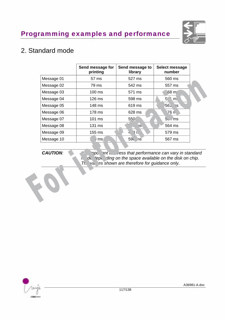
Programming examples and performance
A36981-A.doc117/138
2. Standard mode
Send message for printing
Send message to library
Select message number
Message 01 57 ms 527 ms 560 ms Message 02 79 ms 542 ms 557 ms Message 03 100 ms 571 ms 568 ms Message 04 126 ms 598 ms 561 ms Message 05 148 ms 619 ms 561 ms Message 06 178 ms 628 ms 576 ms Message 07 101 ms 550 ms 564 ms Message 08 131 ms 590 ms 564 ms Message 09 155 ms 428 ms 579 ms Message 10 130 ms 590 ms 567 ms
CAUTION: It is important to stress that performance can vary in standard mode depending on the space available on the disk on chip. The values shown are therefore for guidance only.
For information

A36981-A.doc118/138
For information

A36981-A.doc119/138
Parallel link - Presentation
For information

Parallel link - Presentation
A36981-A.doc120/138
For information
Parallel link - Presentation
A36981-A.doc121/138
■ Introduction The Parallel Interface can be used to quickly select and print a message stored in the library. The "Message selection" and "Message library" options are required for this method of operation. The printer's display is not refreshed when the printer is used in this way.
For information
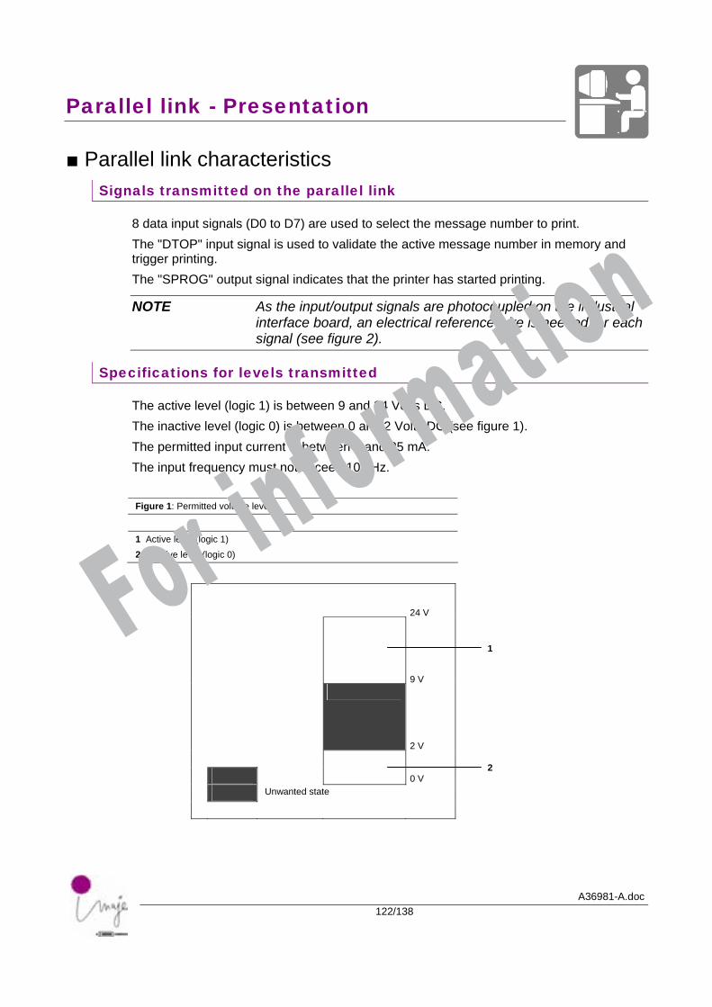
Parallel link - Presentation
A36981-A.doc122/138
■ Parallel link characteristics Signals transmitted on the parallel link
8 data input signals (D0 to D7) are used to select the message number to print. The "DTOP" input signal is used to validate the active message number in memory and trigger printing. The "SPROG" output signal indicates that the printer has started printing.
NOTE As the input/output signals are photocoupled on the industrial interface board, an electrical reference wire is needed for each signal (see figure 2).
Specifications for levels transmitted
The active level (logic 1) is between 9 and 24 Volts DC. The inactive level (logic 0) is between 0 and 2 Volts DC (see figure 1). The permitted input current is between 9 and 25 mA. The input frequency must not exceed 10 kHz. Figure 1: Permitted voltage levels
1 Active level (logic 1) 2 Inactive level (logic 0)
1
24 V
9 V
2 V
0 V 2
Unwanted state
For information
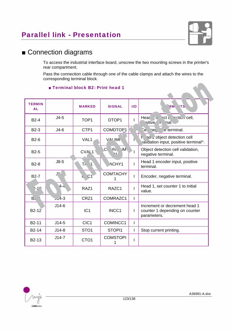
Parallel link - Presentation
A36981-A.doc123/138
■ Connection diagrams To access the industrial interface board, unscrew the two mounting screws in the printer's rear compartment. Pass the connection cable through one of the cable clamps and attach the wires to the corresponding terminal block.
■ Terminal block B2: Print head 1
TERMINAL
MARKED SIGNAL I/O COMMENTS
B2-4 J4-5 TOP1 DTOP1 I Head 1 object detection cell, positive terminal.
B2-3 J4-6 CTP1 COMDTOP1 I Cell, negative terminal.
B2-6 VAL1 VALIMP1 I Head 1 object detection cell validation input, positive terminal^.
B2-5 CVAL1 COMVALIMP1 I Object detection cell validation,
negative terminal.
B2-8 J8-5 TAC1 TACHY1 I Head 1 encoder input, positive terminal.
B2-7 J8-6 CTC1 COMTACHY1 I Encoder, negative terminal.
B2-10 J14-4 RAZ1 RAZC1 I Head 1, set counter 1 to initial value.
B2-9 J14-3 CRZ1 COMRAZC1 I
B2-12 J14-6
IC1 INCC1 I Increment or decrement head 1 counter 1 depending on counter parameters.
B2-11 J14-5 CIC1 COMINCC1 I
B2-14 J14-8 STO1 STOPI1 I Stop current printing.
B2-13 J14-7 CTO1 COMSTOPI1 I
For information
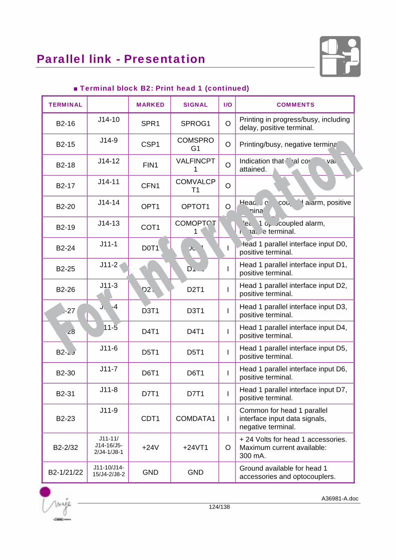
Parallel link - Presentation
A36981-A.doc124/138
■ Terminal block B2: Print head 1 (continued)
TERMINAL MARKED SIGNAL I/O COMMENTS
B2-16 J14-10 SPR1 SPROG1 O Printing in progress/busy, including delay, positive terminal.
B2-15 J14-9 CSP1 COMSPROG1 O Printing/busy, negative terminal.
B2-18 J14-12 FIN1 VALFINCPT1 O Indication that final counter value
attained.
B2-17 J14-11 CFN1 COMVALCPT1 O
B2-20 J14-14 OPT1 OPTOT1 O Head 1 optocoupled alarm, positive terminal.
B2-19 J14-13 COT1 COMOPTOT1 O Head 1 optocoupled alarm,
negative terminal.
B2-24 J11-1 D0T1 D0T1 I Head 1 parallel interface input D0, positive terminal.
B2-25 J11-2 D1T1 D1T1 I Head 1 parallel interface input D1, positive terminal.
B2-26 J11-3 D2T1 D2T1 I Head 1 parallel interface input D2, positive terminal.
B2-27 J11-4 D3T1 D3T1 I Head 1 parallel interface input D3, positive terminal.
B2-28 J11-5 D4T1 D4T1 I Head 1 parallel interface input D4, positive terminal.
B2-29 J11-6 D5T1 D5T1 I Head 1 parallel interface input D5, positive terminal.
B2-30 J11-7 D6T1 D6T1 I Head 1 parallel interface input D6, positive terminal.
B2-31 J11-8 D7T1 D7T1 I Head 1 parallel interface input D7, positive terminal.
B2-23 J11-9
CDT1 COMDATA1 I Common for head 1 parallel interface input data signals, negative terminal.
B2-2/32 J11-11/
J14-16/J5-2/J4-1/J8-1
+24V +24VT1 O + 24 Volts for head 1 accessories. Maximum current available: 300 mA.
B2-1/21/22 J11-10/J14-15/J4-2/J8-2 GND GND Ground available for head 1
accessories and optocouplers.
For information
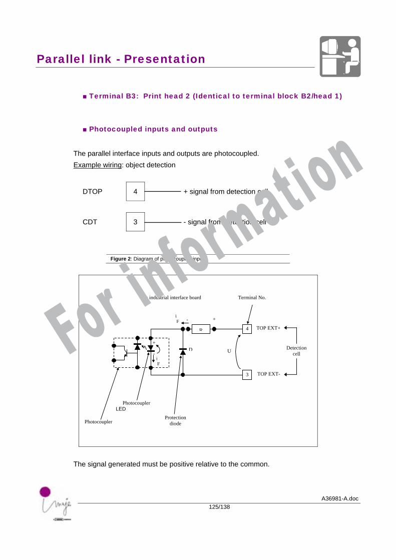
Parallel link - Presentation
A36981-A.doc125/138
■ Terminal B3: Print head 2 (Identical to terminal block B2/head 1)
■ Photocoupled inputs and outputs
The parallel interface inputs and outputs are photocoupled. Example wiring: object detection
DTOP 4 + signal from detection cell
CDT 3 - signal from detection cell
Figure 2: Diagram of photocoupled input
The signal generated must be positive relative to the common.
Detection cell
TOP EXT+
Terminal No. On industrial interface board
Photocoupler
Photocoupler LED
Protection diode
TOP EXT-
D U
R 4
3
+-
-
+
i F
i F For information

A36981-A.doc126/138
For information

A36981-A.doc127/138
Parallel link - Message selection
For information

Parallel link – Message selection
A36981-A.doc128/138
For information
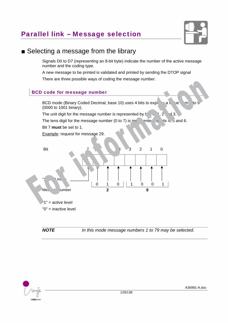
Parallel link – Message selection
A36981-A.doc129/138
■ Selecting a message from the library Signals D0 to D7 (representing an 8-bit byte) indicate the number of the active message number and the coding type. A new message to be printed is validated and printed by sending the DTOP signal There are three possible ways of coding the message number.
BCD code for message number
BCD mode (Binary Coded Decimal, base 10) uses 4 bits to express a value from 0 to 9 (0000 to 1001 binary). The unit digit for the message number is represented by bits 0, 1, 2 and 3. The tens digit for the message number (0 to 7) is represented by bits 4, 5 and 6. Bit 7 must be set to 1. Example: request for message 29.
Bit 7 6 5 4 3 2 1 0
1
"1" BCD mode
0 1 0 1 0 0 1 Message number 2 9 "1" = active level "0" = inactive level
NOTE In this mode message numbers 1 to 79 may be selected.
For information
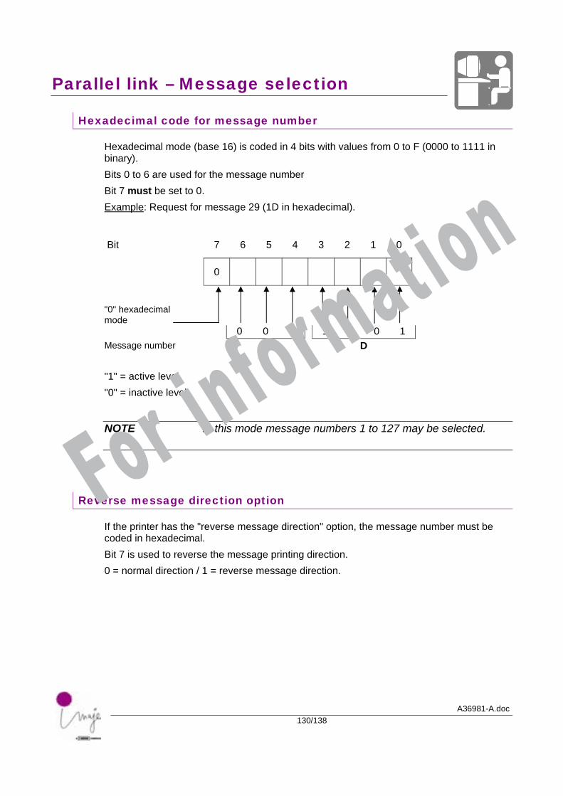
Parallel link – Message selection
A36981-A.doc130/138
Hexadecimal code for message number
Hexadecimal mode (base 16) is coded in 4 bits with values from 0 to F (0000 to 1111 in binary). Bits 0 to 6 are used for the message number Bit 7 must be set to 0. Example: Request for message 29 (1D in hexadecimal).
Bit 7 6 5 4 3 2 1 0
0
"0" hexadecimal mode
0 0 1 1 1 0 1 Message number 1 D "1" = active level "0" = inactive level
NOTE In this mode message numbers 1 to 127 may be selected.
Reverse message direction option
If the printer has the "reverse message direction" option, the message number must be coded in hexadecimal. Bit 7 is used to reverse the message printing direction. 0 = normal direction / 1 = reverse message direction.
For information
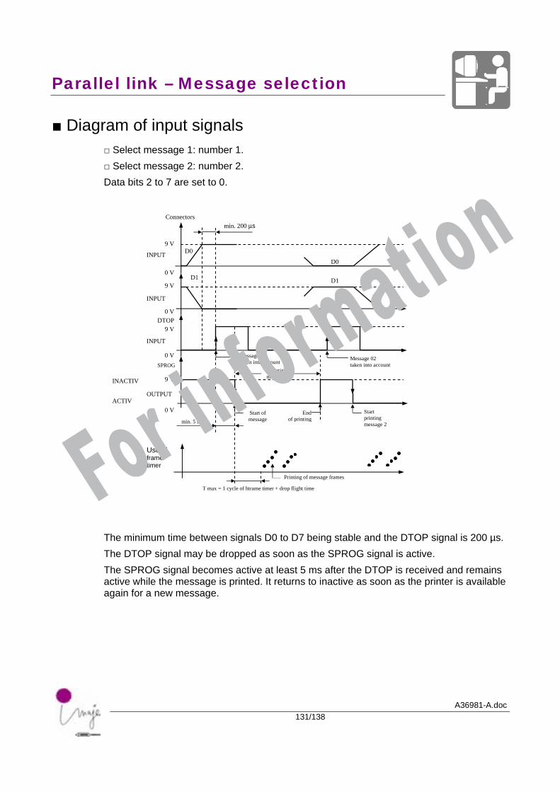
Parallel link – Message selection
A36981-A.doc131/138
■ Diagram of input signals □ Select message 1: number 1. □ Select message 2: number 2. Data bits 2 to 7 are set to 0. The minimum time between signals D0 to D7 being stable and the DTOP signal is 200 µs. The DTOP signal may be dropped as soon as the SPROG signal is active. The SPROG signal becomes active at least 5 ms after the DTOP is received and remains active while the message is printed. It returns to inactive as soon as the printer is available again for a new message.
SPROG
Connectors
9 V
Useful frame timer
INPUT
INPUT
INPUT
OUTPUT
0 V
0 V
0 V
0 V
9 V
9 V
9 V
DTOP
INACTIV
ACTIV
D0
D1 D1
D0
min. 200 µs
min. 5 ms Start of message
Start printing message 2
End of printing
Printing of message frames
T max = 1 cycle of htrame timer + drop flight time
Printing message 1
Message 02 taken into account
Message 01 taken into account
For information
Parallel link – Message selection
A36981-A.doc132/138
■ General parallel link operation To print a message from the library: □ Present the message number to print on the parallel interface (D0-D7) of the corresponding head. □ Activated the DTOP signal which:
. memorizes the message number,
. initiates printing. The SPROG signal is active during printing and becomes inactive once the print cycle is complete. A print cycle comprises: □ printing the message, □ phase detection. When the parallel interface is used in AUTO mode, the SPROG signal operates as described above for each message printed. It can therefore be used to change the message even in this trigger mode. If the printer receives a DTOP signal without the external inputs activated, it prints the last message selected. If the printer receives an invalid message number, it prints the last message selected. The message number must be between 1 and the size of the library. Any numbers greater than the size of the library are not valid.
■ Restriction on parallel interface operation □ The "Non-double printing" cannot be used with the "Message selection" option. For information
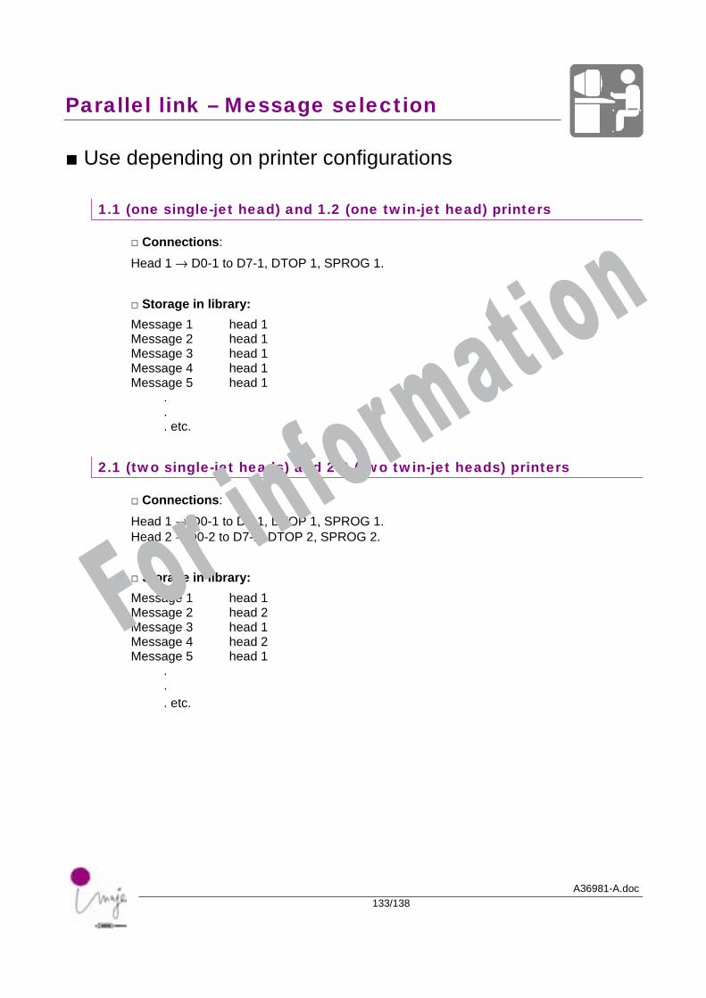
Parallel link – Message selection
A36981-A.doc133/138
■ Use depending on printer configurations
1.1 (one single-jet head) and 1.2 (one twin-jet head) printers
□ Connections:
Head 1 → D0-1 to D7-1, DTOP 1, SPROG 1. □ Storage in library: Message 1 head 1 Message 2 head 1 Message 3 head 1 Message 4 head 1 Message 5 head 1 . . . etc.
2.1 (two single-jet heads) and 2.2 (two twin-jet heads) printers
□ Connections:
Head 1 → D0-1 to D7-1, DTOP 1, SPROG 1. Head 2 →D0-2 to D7-2, DTOP 2, SPROG 2. □ Storage in library: Message 1 head 1 Message 2 head 2 Message 3 head 1 Message 4 head 2 Message 5 head 1 . . . etc.
For information

A36981-A.doc134/138
For information
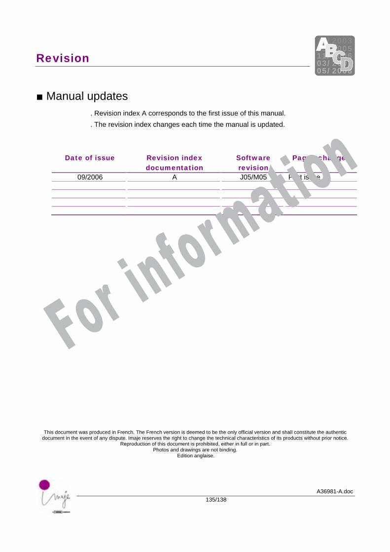
Revision
A36981-A.doc135/138
12/ 200305/ 200511/ 200603/ 200705/ 2008
■ Manual updates . Revision index A corresponds to the first issue of this manual. . The revision index changes each time the manual is updated.
Date of issue Revision index documentation
Software revision
Pages changed
09/2006 A J05/M05 First issue
This document was produced in French. The French version is deemed to be the only official version and shall constitute the authentic document in the event of any dispute. Imaje reserves the right to change the technical characteristics of its products without prior notice.
Reproduction of this document is prohibited, either in full or in part. Photos and drawings are not binding.
Edition anglaise.
For information

For information

For information

Imaje S.A. Siège social : 9, rue Gaspard Monge BP 110 26501 Bourg-lès-Valence Cedex France Tel.: (33) 04 75 75 55 00 Fax: (33) 04 75 82 98 10 http:// www.imaje.com
Man
uals
Dep
artm
ent –
Imaj
e S
.A.
A36981-A
For information