manual hl eng
Post on 29-Aug-2014
79 views
TRANSCRIPT

INSTALLATION SHOULD ONLY BE PERFORMED BY QUALIFIED
INSTALLATION PERSONNEL AND MUST CONFORM TO ALL NATIONAL AND
LOCAL CODES
WARNING

Hyundai Robot
HRLadder
Hi5HL110915FMEN3
Hi5 Controller Function Manual

The information included in this manual is the property of HHI. This manual may not be copied, in part or in full, without prior written authorization from HHI.
It may not be provided to any third party, nor used for any other purposes.
HHI reserves the right to modify the content of this manual without prior notification.
Printed in Korea –Sep 2011 3st
Edition
Copyright ⓒ 2009 by Hyundai Heavy Industries Co., Ltd

i
1. Introduction ..................................................................................................................................... 1-1
1.1. Preliminary Knowledge ....................................................................................................... 1-2 1.2. About HRLadder ................................................................................................................... 1-3 1.3. Execution Environment of HRLadder ................................................................................ 1-3 1.4. Wiring Method of RS-232C Cable ....................................................................................... 1-4 1.5. Configuration Method of Ethernet Environment ............................................................... 1-5
2. Install and Start HRLadder ............................................................................................................. 2-1
2.1. Install HRLadder ................................................................................................................... 2-2 2.2. Start HRLadder ..................................................................................................................... 2-4 2.3. License Input ........................................................................................................................ 2-5 2.4. Project Management ............................................................................................................ 2-7 2.5. Window arrangement ......................................................................................................... 2-10
3. Edit Ladder Diagram ...................................................................................................................... 3-1
3.1. Basic Edit .............................................................................................................................. 3-2 3.2. Edit Branch ........................................................................................................................... 3-4 3.3. Delete, Cut, Copy, Paste and Cancel .................................................................................. 3-6 3.4. Tag Format ............................................................................................................................ 3-7 3.5. Note and Relay Description Table ...................................................................................... 3-9 3.6. Find and Replace................................................................................................................ 3-13 3.7. Syntax Check ...................................................................................................................... 3-15
4. Communication Setting ................................................................................................................. 4-1
4.1. RS-232C Communication Setting ....................................................................................... 4-2 4.1.1. Hi5 Controller Side Setting ........................................................................................... 4-2 4.1.2. PC Side Setting ............................................................................................................ 4-3
4.2. RS-232C Communication Troubleshooting ....................................................................... 4-5 4.2.1. PC Side Loopback Test Method ................................................................................... 4-6 4.2.2. Controller Side Loopback Test Method ...................................................................... 4-11
4.3. Ethernet Communication Setting ..................................................................................... 4-14 4.3.1. Hi5 Controller Side Setting ......................................................................................... 4-14 4.3.2. PC Side Setting .......................................................................................................... 4-15
4.4. Ethernet Communication Troubleshooting ..................................................................... 4-18
5. File Upload/Download .................................................................................................................... 5-1
5.1. Ladder file ............................................................................................................................. 5-2 5.1.1. Hi5 controller ................................................................................................................ 5-2 5.1.2. Hi4a controller .............................................................................................................. 5-2
5.2. Download .............................................................................................................................. 5-3 5.2.1. Download selected ladder window............................................................................... 5-3 5.2.2. Download in Workspace .............................................................................................. 5-5
5.3. Upload ................................................................................................................................... 5-6 5.3.1. Upload main program in ladder window ...................................................................... 5-6
Contents

Contents
ii
5.3.2. Upload from Workspace ............................................................................................... 5-7
6. Monitoring ....................................................................................................................................... 6-1
6.1. PLC Monitoring..................................................................................................................... 6-2 6.2. Reset All Relays ................................................................................................................... 6-8 6.3. Manual Output ...................................................................................................................... 6-9 6.4. Status Bar Information ....................................................................................................... 6-10
iii
그림 목차
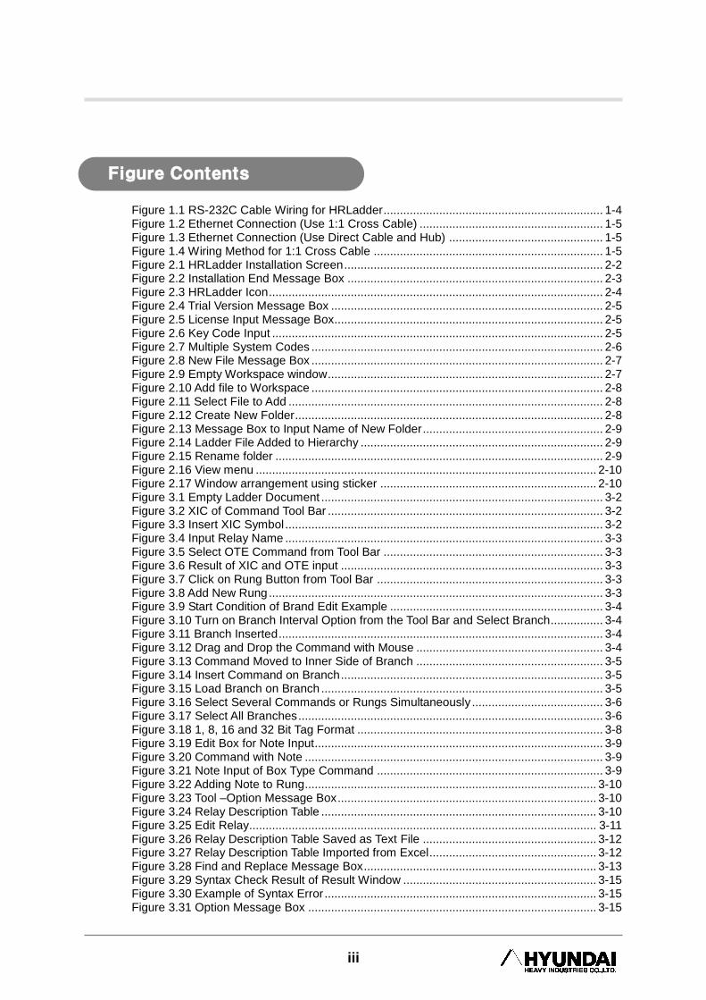
Figure 1.1 RS-232C Cable Wiring for HRLadder ................................................................... 1-4 Figure 1.2 Ethernet Connection (Use 1:1 Cross Cable) ........................................................ 1-5 Figure 1.3 Ethernet Connection (Use Direct Cable and Hub) ............................................... 1-5 Figure 1.4 Wiring Method for 1:1 Cross Cable ...................................................................... 1-5 Figure 2.1 HRLadder Installation Screen ............................................................................... 2-2 Figure 2.2 Installation End Message Box .............................................................................. 2-3 Figure 2.3 HRLadder Icon ...................................................................................................... 2-4 Figure 2.4 Trial Version Message Box ................................................................................... 2-5 Figure 2.5 License Input Message Box.................................................................................. 2-5 Figure 2.6 Key Code Input ..................................................................................................... 2-5 Figure 2.7 Multiple System Codes ......................................................................................... 2-6 Figure 2.8 New File Message Box ......................................................................................... 2-7 Figure 2.9 Empty Workspace window .................................................................................... 2-7 Figure 2.10 Add file to Workspace ......................................................................................... 2-8 Figure 2.11 Select File to Add ................................................................................................ 2-8 Figure 2.12 Create New Folder .............................................................................................. 2-8 Figure 2.13 Message Box to Input Name of New Folder ....................................................... 2-9 Figure 2.14 Ladder File Added to Hierarchy .......................................................................... 2-9 Figure 2.15 Rename folder .................................................................................................... 2-9 Figure 2.16 View menu ........................................................................................................ 2-10 Figure 2.17 Window arrangement using sticker .................................................................. 2-10 Figure 3.1 Empty Ladder Document ...................................................................................... 3-2 Figure 3.2 XIC of Command Tool Bar .................................................................................... 3-2 Figure 3.3 Insert XIC Symbol ................................................................................................. 3-2 Figure 3.4 Input Relay Name ................................................................................................. 3-3 Figure 3.5 Select OTE Command from Tool Bar ................................................................... 3-3 Figure 3.6 Result of XIC and OTE input ................................................................................ 3-3 Figure 3.7 Click on Rung Button from Tool Bar ..................................................................... 3-3 Figure 3.8 Add New Rung ...................................................................................................... 3-3 Figure 3.9 Start Condition of Brand Edit Example ................................................................. 3-4 Figure 3.10 Turn on Branch Interval Option from the Tool Bar and Select Branch................ 3-4 Figure 3.11 Branch Inserted ................................................................................................... 3-4 Figure 3.12 Drag and Drop the Command with Mouse ......................................................... 3-4 Figure 3.13 Command Moved to Inner Side of Branch ......................................................... 3-5 Figure 3.14 Insert Command on Branch ................................................................................ 3-5 Figure 3.15 Load Branch on Branch ...................................................................................... 3-5 Figure 3.16 Select Several Commands or Rungs Simultaneously ........................................ 3-6 Figure 3.17 Select All Branches ............................................................................................. 3-6 Figure 3.18 1, 8, 16 and 32 Bit Tag Format ........................................................................... 3-8 Figure 3.19 Edit Box for Note Input ........................................................................................ 3-9 Figure 3.20 Command with Note ........................................................................................... 3-9 Figure 3.21 Note Input of Box Type Command ..................................................................... 3-9 Figure 3.22 Adding Note to Rung ......................................................................................... 3-10 Figure 3.23 Tool –Option Message Box ............................................................................... 3-10 Figure 3.24 Relay Description Table .................................................................................... 3-10 Figure 3.25 Edit Relay.......................................................................................................... 3-11 Figure 3.26 Relay Description Table Saved as Text File ..................................................... 3-12 Figure 3.27 Relay Description Table Imported from Excel ................................................... 3-12 Figure 3.28 Find and Replace Message Box ....................................................................... 3-13 Figure 3.29 Syntax Check Result of Result Window ........................................................... 3-15 Figure 3.30 Example of Syntax Error ................................................................................... 3-15 Figure 3.31 Option Message Box ........................................................................................ 3-15
Figure Contents
Contents
iv
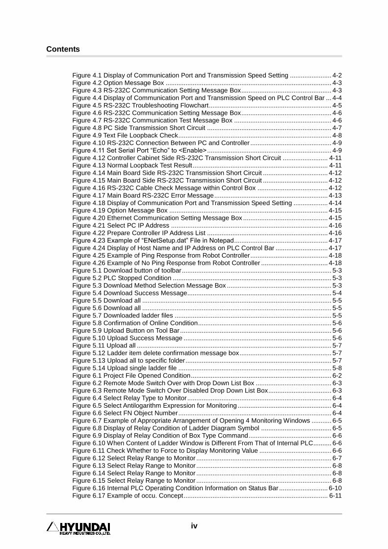
Figure 4.1 Display of Communication Port and Transmission Speed Setting ....................... 4-2 Figure 4.2 Option Message Box ............................................................................................ 4-3 Figure 4.3 RS-232C Communication Setting Message Box .................................................. 4-3 Figure 4.4 Display of Communication Port and Transmission Speed on PLC Control Bar ... 4-4 Figure 4.5 RS-232C Troubleshooting Flowchart .................................................................... 4-5 Figure 4.6 RS-232C Communication Setting Message Box .................................................. 4-6 Figure 4.7 RS-232C Communication Test Message Box ...................................................... 4-6 Figure 4.8 PC Side Transmission Short Circuit ..................................................................... 4-7 Figure 4.9 Text File Loopback Check ..................................................................................... 4-8 Figure 4.10 RS-232C Connection Between PC and Controller ............................................. 4-9 Figure 4.11 Set Serial Port “Echo” to <Enable> ..................................................................... 4-9 Figure 4.12 Controller Cabinet Side RS-232C Transmission Short Circuit ......................... 4-11 Figure 4.13 Normal Loopback Test Result ........................................................................... 4-11 Figure 4.14 Main Board Side RS-232C Transmission Short Circuit .................................... 4-12 Figure 4.15 Main Board Side RS-232C Transmission Short Circuit .................................... 4-12 Figure 4.16 RS-232C Cable Check Message within Control Box ....................................... 4-12 Figure 4.17 Main Board RS-232C Error Message ............................................................... 4-13 Figure 4.18 Display of Communication Port and Transmission Speed Setting ................... 4-14 Figure 4.19 Option Message Box ........................................................................................ 4-15 Figure 4.20 Ethernet Communication Setting Message Box ............................................... 4-15 Figure 4.21 Select PC IP Address ....................................................................................... 4-16 Figure 4.22 Prepare Controller IP Address List ................................................................... 4-16 Figure 4.23 Example of “ENetSetup.dat” File in Notepad .................................................... 4-17 Figure 4.24 Display of Host Name and IP Address on PLC Control Bar ............................. 4-17 Figure 4.25 Example of Ping Response from Robot Controller ........................................... 4-18 Figure 4.26 Example of No Ping Response from Robot Controller ..................................... 4-18 Figure 5.1 Download button of toolbar ................................................................................... 5-3 Figure 5.2 PLC Stopped Condition ........................................................................................ 5-3 Figure 5.3 Download Method Selection Message Box .......................................................... 5-3 Figure 5.4 Download Success Message................................................................................ 5-4 Figure 5.5 Download all ......................................................................................................... 5-5 Figure 5.6 Download all ......................................................................................................... 5-5 Figure 5.7 Downloaded ladder files ....................................................................................... 5-5 Figure 5.8 Confirmation of Online Condition .......................................................................... 5-6 Figure 5.9 Upload Button on Tool Bar .................................................................................... 5-6 Figure 5.10 Upload Success Message .................................................................................. 5-6 Figure 5.11 Upload all ............................................................................................................ 5-7 Figure 5.12 Ladder item delete confirmation message box ................................................... 5-7 Figure 5.13 Upload all to specific folder ................................................................................. 5-7 Figure 5.14 Upload single ladder file ..................................................................................... 5-8 Figure 6.1 Project File Opened Condition .............................................................................. 6-2 Figure 6.2 Remote Mode Switch Over with Drop Down List Box .......................................... 6-3 Figure 6.3 Remote Mode Switch Over Disabled Drop Down List Box ................................... 6-3 Figure 6.4 Select Relay Type to Monitor ................................................................................ 6-4 Figure 6.5 Select Antilogarithm Expression for Monitoring .................................................... 6-4 Figure 6.6 Select FN Object Number ..................................................................................... 6-4 Figure 6.7 Example of Appropriate Arrangement of Opening 4 Monitoring Windows ........... 6-5 Figure 6.8 Display of Relay Condition of Ladder Diagram Symbol ....................................... 6-5 Figure 6.9 Display of Relay Condition of Box Type Command .............................................. 6-6 Figure 6.10 When Content of Ladder Window is Different From That of Internal PLC .......... 6-6 Figure 6.11 Check Whether to Force to Display Monitoring Value ........................................ 6-6 Figure 6.12 Select Relay Range to Monitor ........................................................................... 6-7 Figure 6.13 Select Relay Range to Monitor ........................................................................... 6-8 Figure 6.14 Select Relay Range to Monitor ........................................................................... 6-8 Figure 6.15 Select Relay Range to Monitor ........................................................................... 6-8 Figure 6.16 Internal PLC Operating Condition Information on Status Bar ........................... 6-10 Figure 6.17 Example of occu. Concept ................................................................................ 6-11
v
표 목차
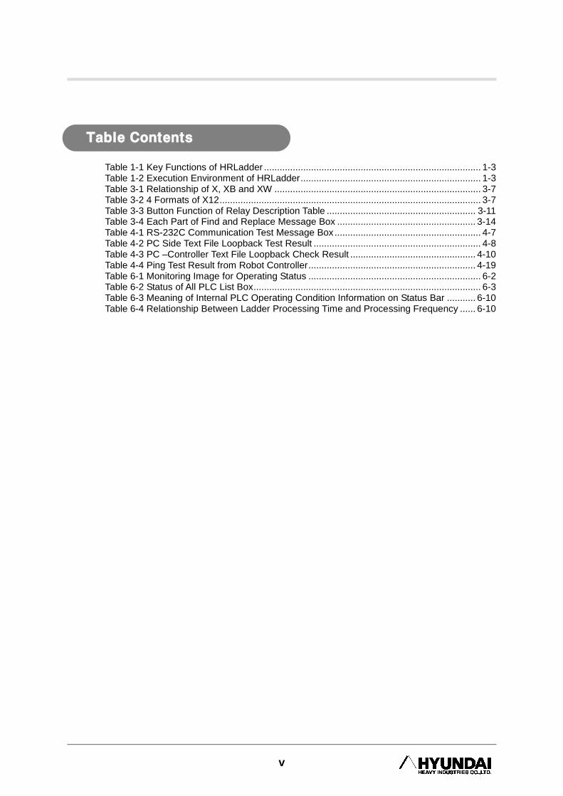
Table 1-1 Key Functions of HRLadder ................................................................................... 1-3 Table 1-2 Execution Environment of HRLadder ..................................................................... 1-3 Table 3-1 Relationship of X, XB and XW ............................................................................... 3-7 Table 3-2 4 Formats of X12 .................................................................................................... 3-7 Table 3-3 Button Function of Relay Description Table ......................................................... 3-11 Table 3-4 Each Part of Find and Replace Message Box ..................................................... 3-14 Table 4-1 RS-232C Communication Test Message Box ........................................................ 4-7 Table 4-2 PC Side Text File Loopback Test Result ................................................................ 4-8 Table 4-3 PC –Controller Text File Loopback Check Result ................................................ 4-10 Table 4-4 Ping Test Result from Robot Controller ................................................................ 4-19 Table 6-1 Monitoring Image for Operating Status .................................................................. 6-2 Table 6-2 Status of All PLC List Box ....................................................................................... 6-3 Table 6-3 Meaning of Internal PLC Operating Condition Information on Status Bar ........... 6-10 Table 6-4 Relationship Between Ladder Processing Time and Processing Frequency ...... 6-10
Table Contents


1. Introduction
1-1
1. Introduction
1 Introduction

HRLadder
1-2
Thank you for using the Hyundai Robot. This manual is based on HRLadder v2.50.
1.1. Preliminary Knowledge To understand this manual well, you must have preliminary knowledge of the following.
How to use Hi5 Controller
Understanding of PLC utilization
How to utilize internal PLC of Hi5 Controller Refer to Hi5 internal PLC functional manual (Command group, operating method etc.)
1. Introduction
1. Introduction
1-3
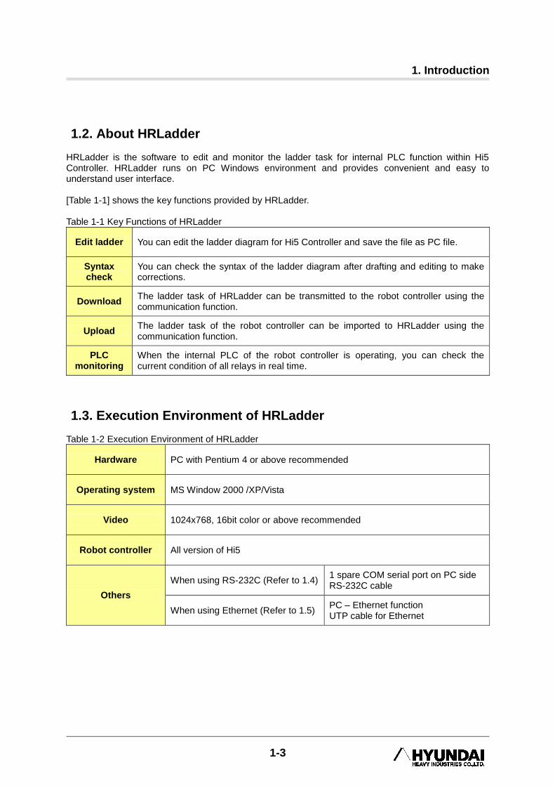
1.2. About HRLadder HRLadder is the software to edit and monitor the ladder task for internal PLC function within Hi5 Controller. HRLadder runs on PC Windows environment and provides convenient and easy to understand user interface. [Table 1-1] shows the key functions provided by HRLadder. Table 1-1 Key Functions of HRLadder
Edit ladder You can edit the ladder diagram for Hi5 Controller and save the file as PC file.
Syntax check
You can check the syntax of the ladder diagram after drafting and editing to make corrections.
Download The ladder task of HRLadder can be transmitted to the robot controller using the communication function.
Upload The ladder task of the robot controller can be imported to HRLadder using the communication function.
PLC monitoring
When the internal PLC of the robot controller is operating, you can check the current condition of all relays in real time.
1.3. Execution Environment of HRLadder Table 1-2 Execution Environment of HRLadder
Hardware PC with Pentium 4 or above recommended
Operating system MS Window 2000 /XP/Vista
Video 1024x768, 16bit color or above recommended
Robot controller All version of Hi5
Others
When using RS-232C (Refer to 1.4) 1 spare COM serial port on PC side RS-232C cable
When using Ethernet (Refer to 1.5) PC – Ethernet function UTP cable for Ethernet
HRLadder
1-4
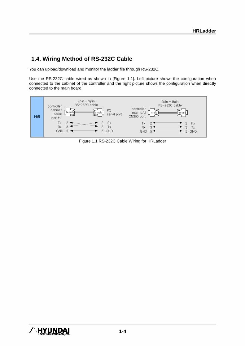
1.4. Wiring Method of RS-232C Cable You can upload/download and monitor the ladder file through RS-232C. Use the RS-232C cable wired as shown in [Figure 1.1]. Left picture shows the configuration when connected to the cabinet of the controller and the right picture shows the configuration when directly connected to the main board.
9pin - 9pin RS-232C cable
2 2
3 3
5 5
Tx Rx
Rx Tx
GND GND
9pin - 9pin RS-232C cable
2 2
3 3
5 5
Tx Rx
Rx Tx
GND GND
controllercabinet
serial port#1Hi5
female femalefemale malePCserial port
controllermain b/d
CNSIO port
Figure 1.1 RS-232C Cable Wiring for HRLadder
1. Introduction
1-5
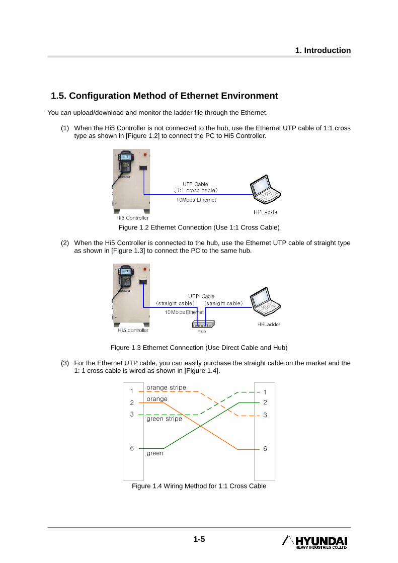
1.5. Configuration Method of Ethernet Environment You can upload/download and monitor the ladder file through the Ethernet.
(1) When the Hi5 Controller is not connected to the hub, use the Ethernet UTP cable of 1:1 cross type as shown in [Figure 1.2] to connect the PC to Hi5 Controller.
Figure 1.2 Ethernet Connection (Use 1:1 Cross Cable)
(2) When the Hi5 Controller is connected to the hub, use the Ethernet UTP cable of straight type
as shown in [Figure 1.3] to connect the PC to the same hub.
Figure 1.3 Ethernet Connection (Use Direct Cable and Hub)
(3) For the Ethernet UTP cable, you can easily purchase the straight cable on the market and the 1: 1 cross cable is wired as shown in [Figure 1.4].
1
2
3
6
1
2
3
6
orange stripe
orange
green stripe
green
Figure 1.4 Wiring Method for 1:1 Cross Cable


2. Install and Start HRLadder
2-1
2. Install and Start HRLadder
2 Install and Start
HRLadder
HRLadder
2-2
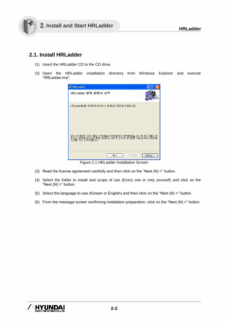
2.1. Install HRLadder
(1) Insert the HRLadder CD to the CD drive.
(2) Open the HRLadder installation directory from Windows Explorer and execute “HRLadder.msi”.
Figure 2.1 HRLadder Installation Screen
(3) Read the license agreement carefully and then click on the “Next (N) >” button.
(4) Select the folder to install and scope of use (Every one or only yourself) and click on the
“Next (N) >” button.
(5) Select the language to use (Korean or English) and then click on the “Next (N) >” button.
(6) From the message screen confirming installation preparation, click on the “Next (N) >” button.
2. Install and Start HRLadder

2. Install and Start HRLadder
2-3
(7) When you see the message box that says that the installation has been completed as shown
in [Figure 2.2], click on the “Close (C)” button.
Figure 2.2 Installation End Message Box

HRLadder
2-4
2.2. Start HRLadder
To execute HRLadder, click on Start and then click on the HRLadder in the 『Program - HRLadder』
folder or double click on the HRLadder icon on the desktop as shown in [Figure 2.3].
Figure 2.3 HRLadder Icon
2. Install and Start HRLadder
2-5
2.3. License Input
Since v2.60 build 1 version, HRLadder has become freeware. Hyundai Robot user‟s can use this software freely without inputting license code. In case that you have to use HRLadder older version(below v2.60), please input license code as following procedure.
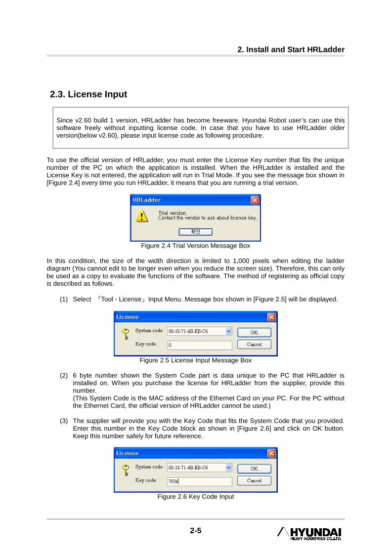
To use the official version of HRLadder, you must enter the License Key number that fits the unique number of the PC on which the application is installed. When the HRLadder is installed and the License Key is not entered, the application will run in Trial Mode. If you see the message box shown in [Figure 2.4] every time you run HRLadder, it means that you are running a trial version.
Figure 2.4 Trial Version Message Box
In this condition, the size of the width direction is limited to 1,000 pixels when editing the ladder diagram (You cannot edit to be longer even when you reduce the screen size). Therefore, this can only be used as a copy to evaluate the functions of the software. The method of registering as official copy is described as follows.
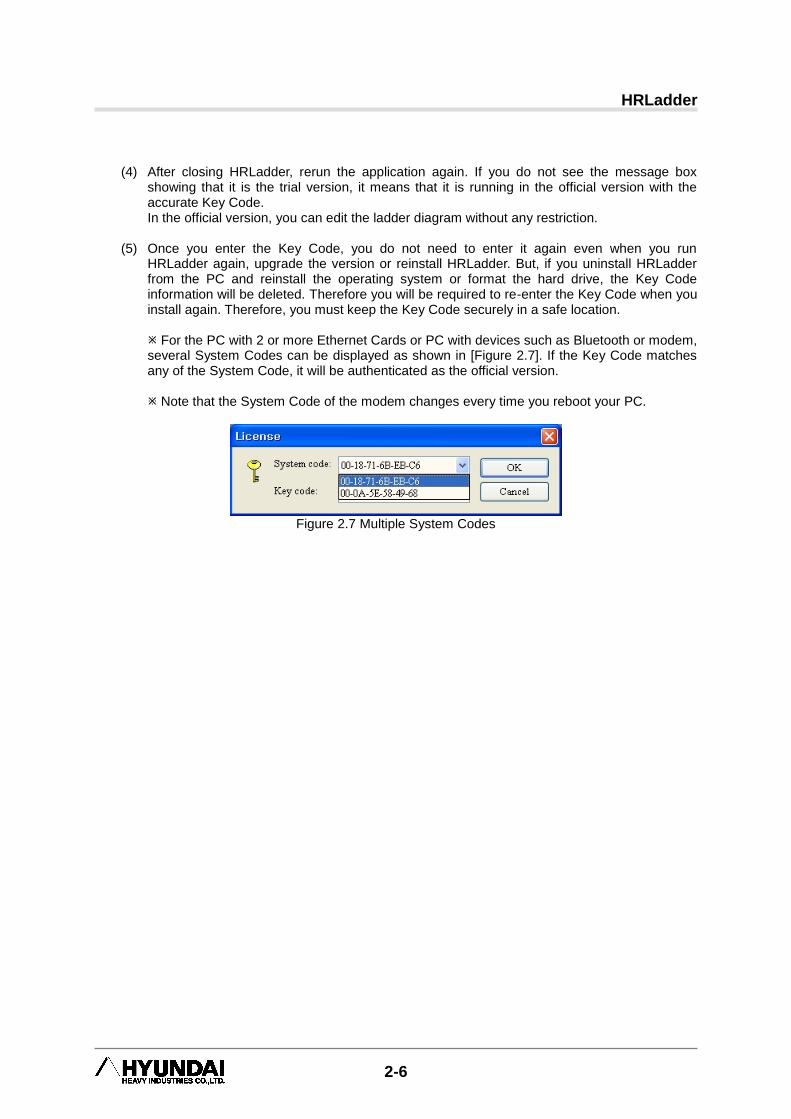
(1) Select 『Tool - License』Input Menu. Message box shown in [Figure 2.5] will be displayed.
Figure 2.5 License Input Message Box
(2) 6 byte number shown the System Code part is data unique to the PC that HRLadder is
installed on. When you purchase the license for HRLadder from the supplier, provide this number. (This System Code is the MAC address of the Ethernet Card on your PC. For the PC without the Ethernet Card, the official version of HRLadder cannot be used.)
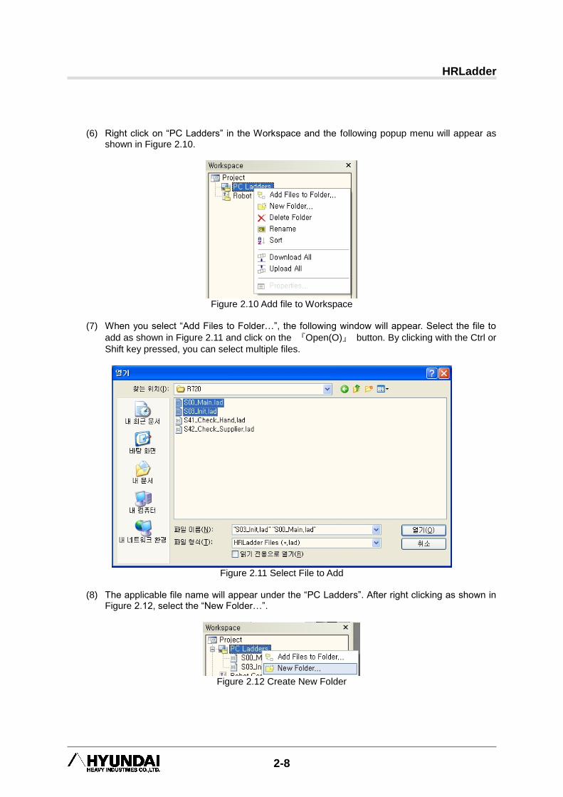
(3) The supplier will provide you with the Key Code that fits the System Code that you provided.
Enter this number in the Key Code block as shown in [Figure 2.6] and click on OK button. Keep this number safely for future reference.
Figure 2.6 Key Code Input
HRLadder
2-6
(4) After closing HRLadder, rerun the application again. If you do not see the message box showing that it is the trial version, it means that it is running in the official version with the accurate Key Code. In the official version, you can edit the ladder diagram without any restriction.
(5) Once you enter the Key Code, you do not need to enter it again even when you run
HRLadder again, upgrade the version or reinstall HRLadder. But, if you uninstall HRLadder from the PC and reinstall the operating system or format the hard drive, the Key Code information will be deleted. Therefore you will be required to re-enter the Key Code when you install again. Therefore, you must keep the Key Code securely in a safe location.
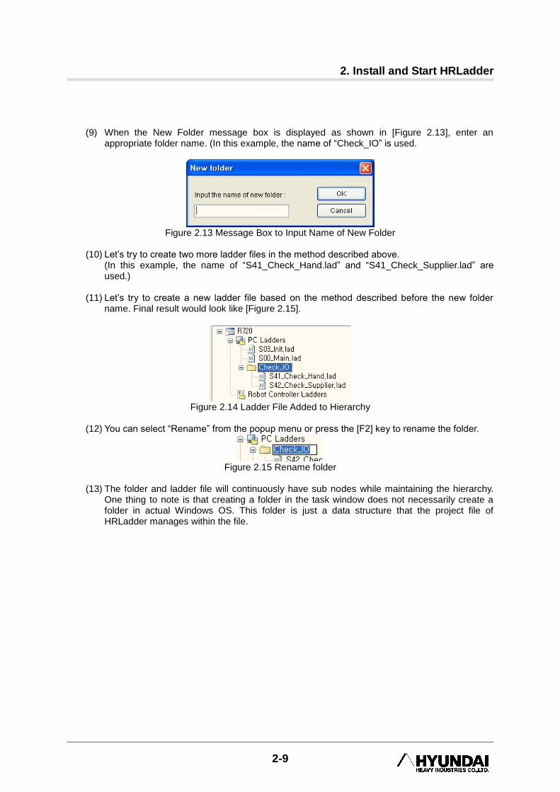
For the PC with 2 or more Ethernet Cards or PC with devices such as Bluetooth or modem, several System Codes can be displayed as shown in [Figure 2.7]. If the Key Code matches any of the System Code, it will be authenticated as the official version.
Note that the System Code of the modem changes every time you reboot your PC.
Figure 2.7 Multiple System Codes

2. Install and Start HRLadder
2-7
2.4. Project Management Let‟s try configuring a project in HRLadder.
(1) Execute HRLadder program.
(2) Select 『File (F) – New File (N)』 from the Menu. As shown in Figure 2.8, a window to select
between the “HRLadder project” (Extension of .HLPRJ) and “Ladder” (Extension of .LAD). The project file manages several ladder files including hierarchical list and relay description etc.
Figure 2.8 New File Message Box
(3) Select “HR Ladder Project” and click on the OK button. Workspace window will appear as
shown in Figure 2.9.
Figure 2.9 Empty Workspace window
(4) Select 『File (F) – Project Save (S)』 and save the project in an appropriate name. (In this
example, the project is saved in the name of “R720.hlprj”.)
(5) Now select 『File (F) – New File (N)』from the menu again and select the “Ladder” item this
time and click on the OK button. When the ladder edit window appears, select 『File (F) –
Save (S)』 to save the ladder file in an appropriate name.
In the same method, let‟s try to create and save some more ladder files. (In this example, the names of “S00_Main.lad” and “S03_Init.lad” are used.)
HRLadder
2-8
(6) Right click on “PC Ladders” in the Workspace and the following popup menu will appear as
shown in Figure 2.10.
Figure 2.10 Add file to Workspace
(7) When you select “Add Files to Folder…”, the following window will appear. Select the file to
add as shown in Figure 2.11 and click on the 『Open(O)』 button. By clicking with the Ctrl or
Shift key pressed, you can select multiple files.
Figure 2.11 Select File to Add
(8) The applicable file name will appear under the “PC Ladders”. After right clicking as shown in
Figure 2.12, select the “New Folder…”.
Figure 2.12 Create New Folder
2. Install and Start HRLadder
2-9
(9) When the New Folder message box is displayed as shown in [Figure 2.13], enter an
appropriate folder name. (In this example, the name of “Check_IO” is used.
Figure 2.13 Message Box to Input Name of New Folder
(10) Let‟s try to create two more ladder files in the method described above.
(In this example, the name of “S41_Check_Hand.lad” and “S41_Check_Supplier.lad” are used.)
(11) Let‟s try to create a new ladder file based on the method described before the new folder
name. Final result would look like [Figure 2.15].
Figure 2.14 Ladder File Added to Hierarchy
(12) You can select “Rename” from the popup menu or press the [F2] key to rename the folder.
Figure 2.15 Rename folder
(13) The folder and ladder file will continuously have sub nodes while maintaining the hierarchy.
One thing to note is that creating a folder in the task window does not necessarily create a folder in actual Windows OS. This folder is just a data structure that the project file of HRLadder manages within the file.
HRLadder
2-10
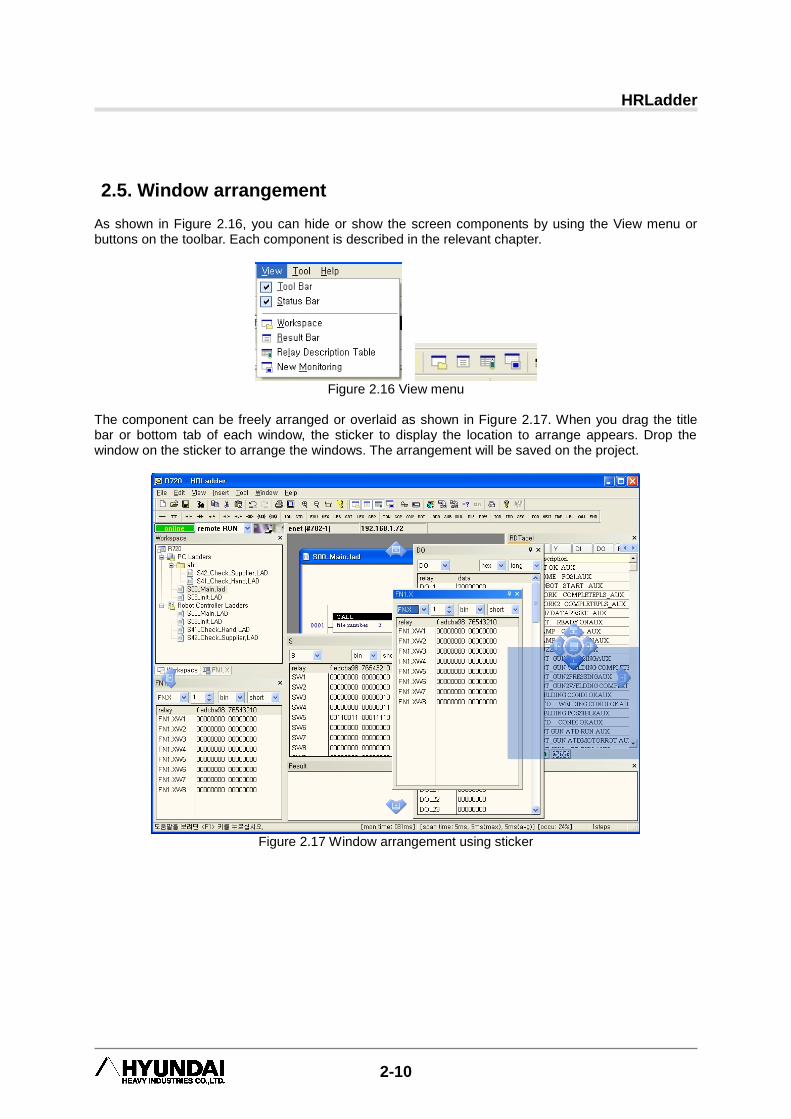
2.5. Window arrangement As shown in Figure 2.16, you can hide or show the screen components by using the View menu or buttons on the toolbar. Each component is described in the relevant chapter.
Figure 2.16 View menu
The component can be freely arranged or overlaid as shown in Figure 2.17. When you drag the title bar or bottom tab of each window, the sticker to display the location to arrange appears. Drop the window on the sticker to arrange the windows. The arrangement will be saved on the project.
Figure 2.17 Window arrangement using sticker

3. Edit Ladder Diagram
3-1
3. Edit Ladder Diagram 3
Edit Ladder Diagram
HRLadder
3-2
3.1. Basic Edit This describes the method of editing the ladder task. Try following as described below.
(1) As described in the previous chapter, create the project and ladder file.
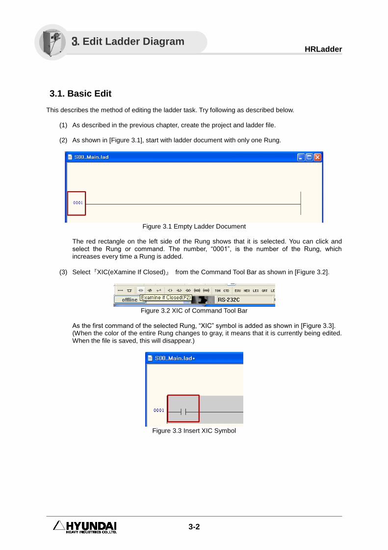
(2) As shown in [Figure 3.1], start with ladder document with only one Rung.
Figure 3.1 Empty Ladder Document
The red rectangle on the left side of the Rung shows that it is selected. You can click and select the Rung or command. The number, “0001”, is the number of the Rung, which increases every time a Rung is added.
(3) Select『XIC(eXamine If Closed)』 from the Command Tool Bar as shown in [Figure 3.2].
Figure 3.2 XIC of Command Tool Bar
As the first command of the selected Rung, “XIC” symbol is added as shown in [Figure 3.3]. (When the color of the entire Rung changes to gray, it means that it is currently being edited. When the file is saved, this will disappear.)
Figure 3.3 Insert XIC Symbol
3. Edit Ladder Diagram
3. Edit Ladder Diagram
3-3
(4) Double click the symbol or press the Enter key when it is selected. The edit box to enter the
tag (operand) will be displayed. Enter the relay name of “X1” as shown in [Figure 3.4]. (All letters will automatically be converted to capital letters.)
Figure 3.4 Input Relay Name
Press the Enter key to complete the entry of the operand of the command. (Incorrect relay name will be displayed in red.)
(5) Now as shown in [Figure 3.5], select the command 『OTE(OuTput Energize)』 from the
Command Tool Bar.
Figure 3.5 Select OTE Command from Tool Bar
As the next command of the selected command, “OTE” will be inserted. As with “XIC”, double click on the symbol or press the Enter to open the edit box and enter “Y1” and press the Enter key. Now it will be as shown in [Figure 3.6]. (The output command is arranged at the right end of the Rung.)
Figure 3.6 Result of XIC and OTE input
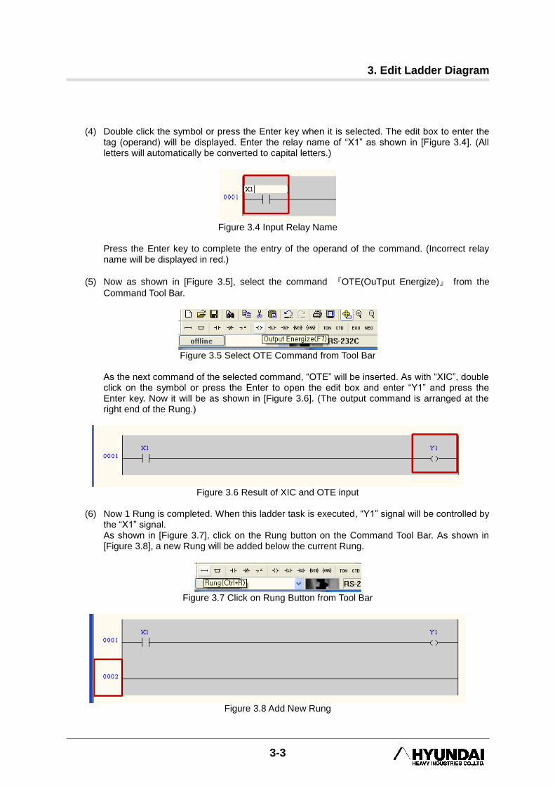
(6) Now 1 Rung is completed. When this ladder task is executed, “Y1” signal will be controlled by
the “X1” signal. As shown in [Figure 3.7], click on the Rung button on the Command Tool Bar. As shown in [Figure 3.8], a new Rung will be added below the current Rung.
Figure 3.7 Click on Rung Button from Tool Bar
Figure 3.8 Add New Rung

HRLadder
3-4
3.2. Edit Branch This describes how to insert and edit the Branch on the Rung. Try following as described below.
(1) Let‟s start from the condition shown in [Figure 3.9].
Figure 3.9 Start Condition of Brand Edit Example
In order to edit the Branch easily, turn on the Branch interval option as shown in [Figure 3.10]. As shown in [Figure 3.10], select the Branch from the Command Tool Bar. The Branch will be added to the Rung as shown in [Figure 3.11].
Figure 3.10 Turn on Branch Interval Option from the Tool Bar and Select Branch
Figure 3.11 Branch Inserted
(2) Try moving “Y1(OTE)” to the inner side of the Branch. There are two ways to do so. You can
drag and drop “Y1” or you can drag one end of the Branch between “X1” and “Y1”. Let‟s try the first method. When you drag “Y1” by left clicking, yellow rectangles will be displayed on the locations where “Y1” can be dropped. When you put the cursor on the location you want to drop, the rectangle will turn red as shown in [Figure 3.12]. In this condition, release the left button of your mouse.
Figure 3.12 Drag and Drop the Command with Mouse
3. Edit Ladder Diagram
3-5
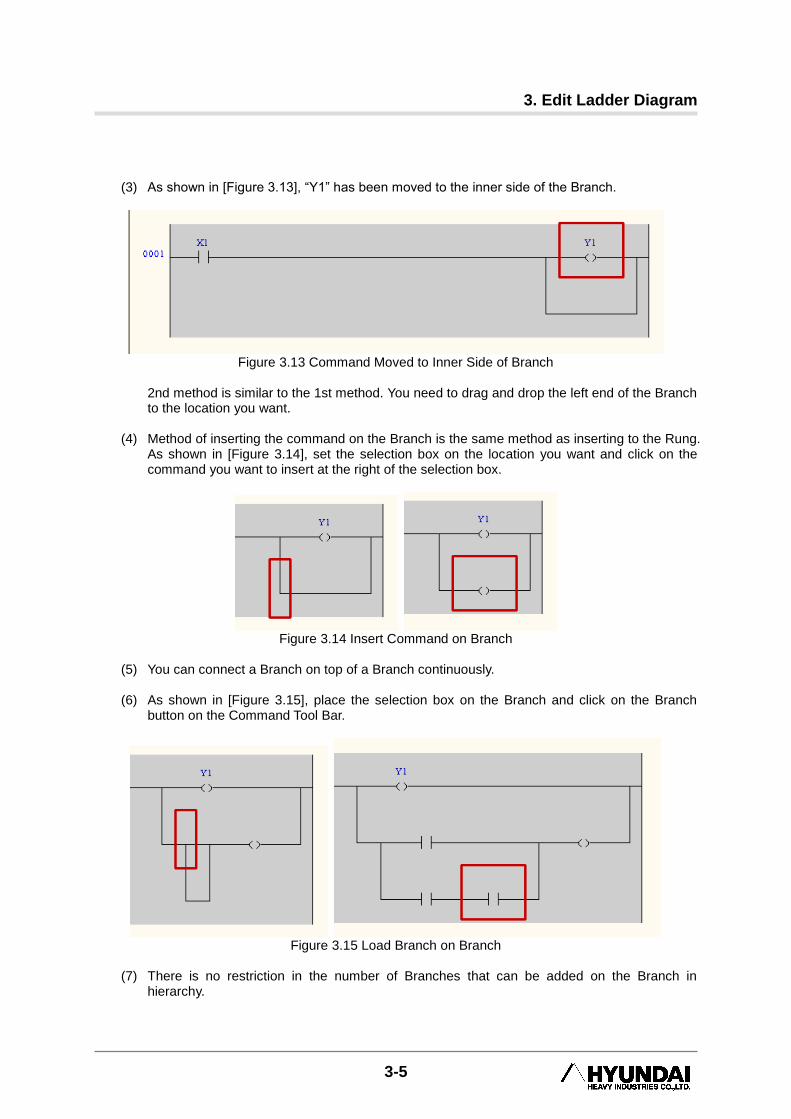
(3) As shown in [Figure 3.13], “Y1” has been moved to the inner side of the Branch.
Figure 3.13 Command Moved to Inner Side of Branch
2nd method is similar to the 1st method. You need to drag and drop the left end of the Branch to the location you want.
(4) Method of inserting the command on the Branch is the same method as inserting to the Rung.
As shown in [Figure 3.14], set the selection box on the location you want and click on the command you want to insert at the right of the selection box.
Figure 3.14 Insert Command on Branch
(5) You can connect a Branch on top of a Branch continuously.
(6) As shown in [Figure 3.15], place the selection box on the Branch and click on the Branch
button on the Command Tool Bar.
Figure 3.15 Load Branch on Branch
(7) There is no restriction in the number of Branches that can be added on the Branch in
hierarchy.

HRLadder
3-6
3.3. Delete, Cut, Copy, Paste and Cancel
(1) When you left click on the command or Rung you want, it will be selected.
(2) When you left click with the [Ctrl] key pressed, you can select multiple commands or Rungs as shown in [Figure 3.16]. But the commands must exist on the same Branch level of the same Rung. Also you cannot select the Rungs with the commands or Branches. When you select multiple objects, Delete/Cut/Copy will be applied to all of the objects.
Figure 3.16 Select Several Commands or Rungs Simultaneously
(3) As shown in [Figure 3.17], when you select the corner of the Branch, the Branch and sub
Branch and the included commands will all be applied.
Figure 3.17 Select All Branches
(4) When you press the [Del] key, the selected commands or selected Rungs or Branches will be
deleted.
(5) When you press the [Ctrl+X] key or click on the button, the selected commands or selected Rungs or Branches will be deleted and copied to the clipboard.
(6) When you press the [Ctrl+C] key or click on the button, the selected commands or selected Rungs or Branches will be copied to the clipboard.
(7) When you press the [Ctrl+V] key or click on the button, the selected commands or selected Rungs or Branches will be copied on the right of the selected location.
(8) When you press the [Ctrl+Z] key or click on the button, the previous edit operation will be canceled.
(9) When you press the [Ctrl+Y] key or click on the button, the previously canceled edit operation will be executed again.
3. Edit Ladder Diagram
3-7
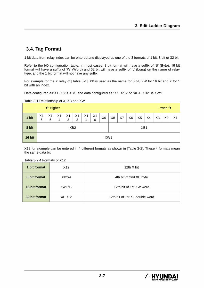
3.4. Tag Format 1 bit data from relay index can be entered and displayed as one of the 3 formats of 1 bit, 8 bit or 32 bit. Refer to the I/O configuration table. In most cases, 8 bit format will have a suffix of „B‟ (Byte), 16 bit format will have a suffix of „W‟ (Word) and 32 bit will have a suffix of „L‟ (Long) on the name of relay type, and the 1 bit format will not have any suffix. For example for the X relay of [Table 3-1], XB is used as the name for 8 bit, XW for 16 bit and X for 1 bit with an index. Data configured as“X1~X8”is XB1, and data configured as “X1~X16” or “XB1~XB2” is XW1. Table 3-1 Relationship of X, XB and XW
Higher Lower
1 bit X16
X15
X14
X13
X12
X11
X10
X9 X8 X7 X6 X5 X4 X3 X2 X1
8 bit XB2 XB1
16 bit XW1
X12 for example can be entered in 4 different formats as shown in [Table 3-2]. These 4 formats mean the same data bit. Table 3-2 4 Formats of X12
1 bit format X12 12th X bit
8 bit format XB2/4 4th bit of 2nd XB byte
16 bit format XW1/12 12th bit of 1st XW word
32 bit format XL1/12 12th bit of 1st XL double word
HRLadder
3-8
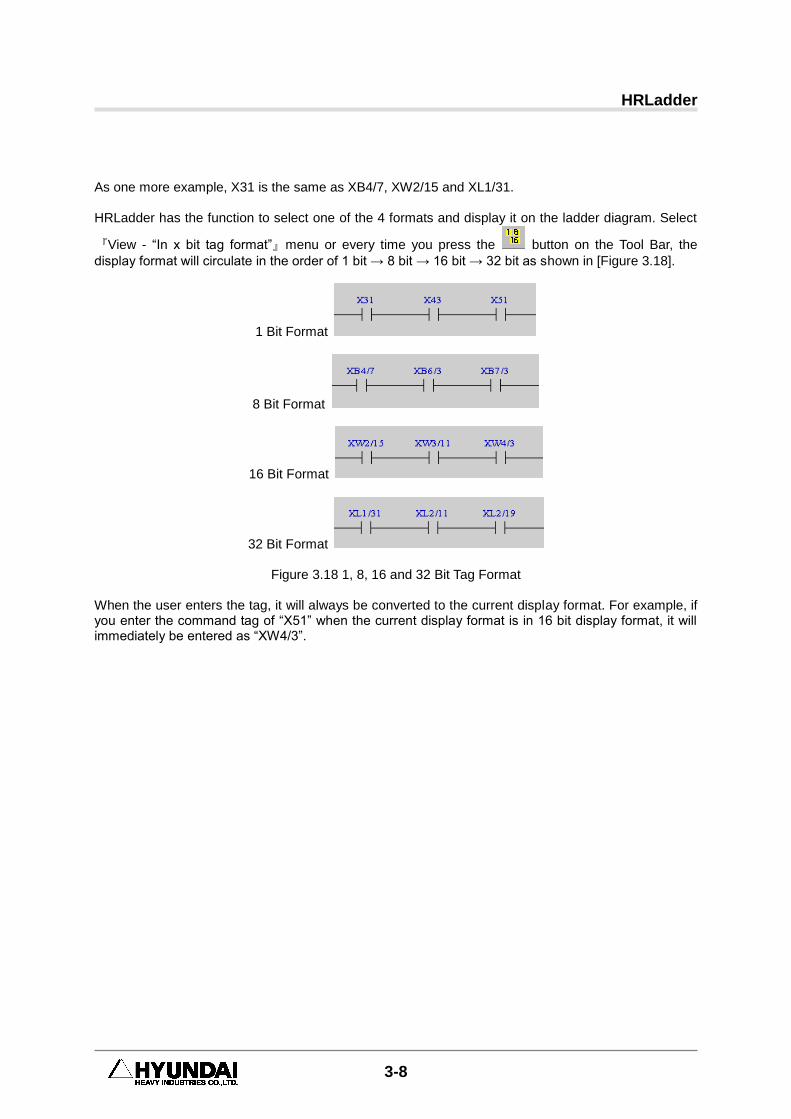
As one more example, X31 is the same as XB4/7, XW2/15 and XL1/31. HRLadder has the function to select one of the 4 formats and display it on the ladder diagram. Select
『View - “In x bit tag format”』menu or every time you press the button on the Tool Bar, the
display format will circulate in the order of 1 bit → 8 bit → 16 bit → 32 bit as shown in [Figure 3.18].
1 Bit Format
8 Bit Format
16 Bit Format
32 Bit Format
Figure 3.18 1, 8, 16 and 32 Bit Tag Format When the user enters the tag, it will always be converted to the current display format. For example, if you enter the command tag of “X51” when the current display format is in 16 bit display format, it will immediately be entered as “XW4/3”.
3. Edit Ladder Diagram
3-9
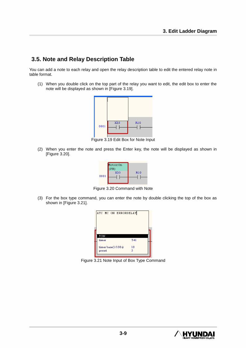
3.5. Note and Relay Description Table You can add a note to each relay and open the relay description table to edit the entered relay note in table format.
(1) When you double click on the top part of the relay you want to edit, the edit box to enter the note will be displayed as shown in [Figure 3.19].
Figure 3.19 Edit Box for Note Input
(2) When you enter the note and press the Enter key, the note will be displayed as shown in
[Figure 3.20].
Figure 3.20 Command with Note
(3) For the box type command, you can enter the note by double clicking the top of the box as
shown in [Figure 3.21].
Figure 3.21 Note Input of Box Type Command
HRLadder
3-10
(4) You can add a note to the Rung as well. After double clicking the Rung number as shown in
[Figure 3.22] enter the note in the edit box and hit Enter when done.
Figure 3.22 Adding Note to Rung
(5) Note information is saved and managed within the project file and not in the ladder file. That
is, the relay note entered applies to all the ladder files opened on the screen. If you would like to save the note to the ladder file and not the project file, open the option message by with
『Tool (T) – Option (O)』 and check the “Save command note to LAD file” item as shown in
[Figure 3.23]. When the note is saved in the ladder file, it will also be downloaded from/uploaded to Controller when the ladder file is downloaded/uploaded.
Figure 3.23 Tool –Option Message Box
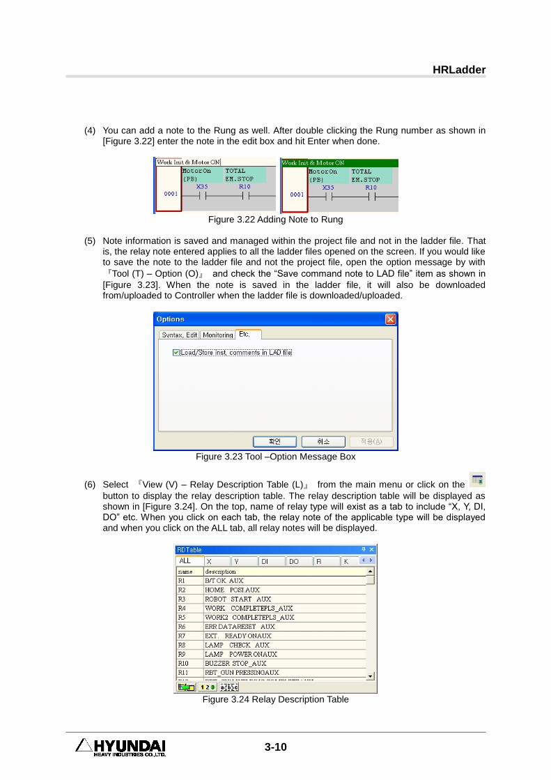
(6) Select 『View (V) – Relay Description Table (L)』 from the main menu or click on the
button to display the relay description table. The relay description table will be displayed as shown in [Figure 3.24]. On the top, name of relay type will exist as a tab to include “X, Y, DI, DO” etc. When you click on each tab, the relay note of the applicable type will be displayed and when you click on the ALL tab, all relay notes will be displayed.
Figure 3.24 Relay Description Table
3. Edit Ladder Diagram
3-11
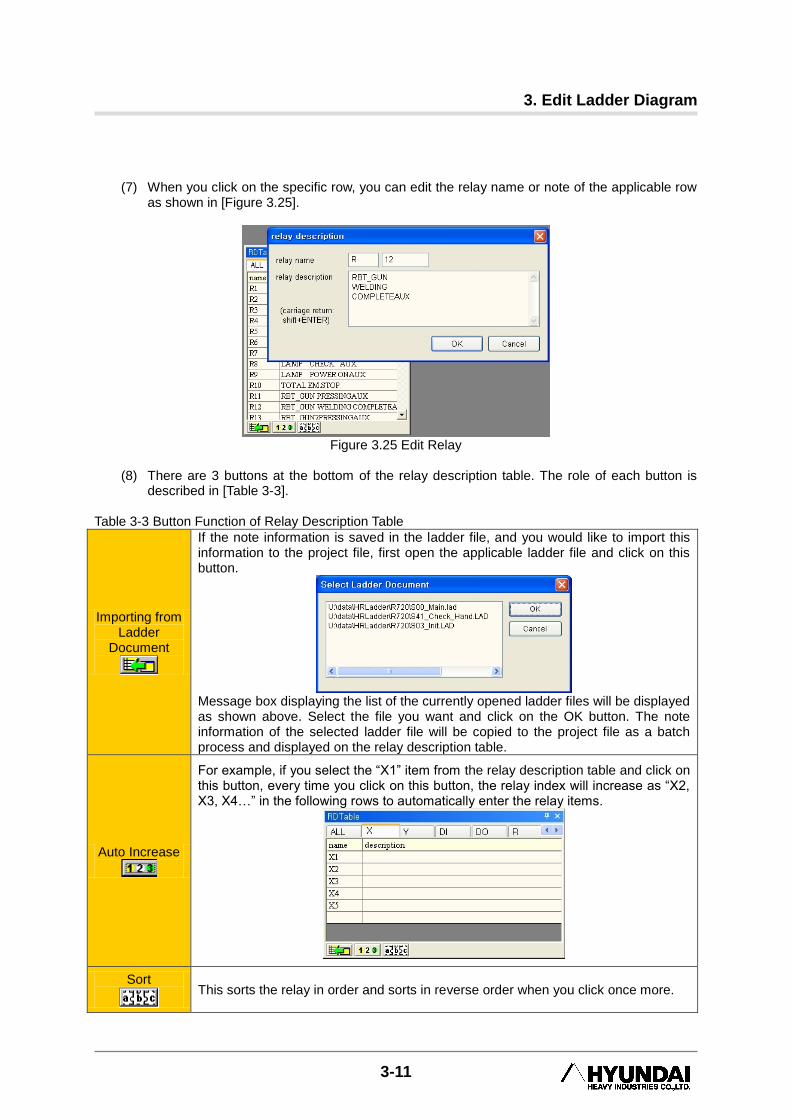
(7) When you click on the specific row, you can edit the relay name or note of the applicable row
as shown in [Figure 3.25].
Figure 3.25 Edit Relay
(8) There are 3 buttons at the bottom of the relay description table. The role of each button is
described in [Table 3-3]. Table 3-3 Button Function of Relay Description Table
Importing from Ladder
Document
If the note information is saved in the ladder file, and you would like to import this information to the project file, first open the applicable ladder file and click on this button.
Message box displaying the list of the currently opened ladder files will be displayed as shown above. Select the file you want and click on the OK button. The note information of the selected ladder file will be copied to the project file as a batch process and displayed on the relay description table.
Auto Increase
For example, if you select the “X1” item from the relay description table and click on this button, every time you click on this button, the relay index will increase as “X2, X3, X4…” in the following rows to automatically enter the relay items.
Sort
This sorts the relay in order and sorts in reverse order when you click once more.
HRLadder
3-12
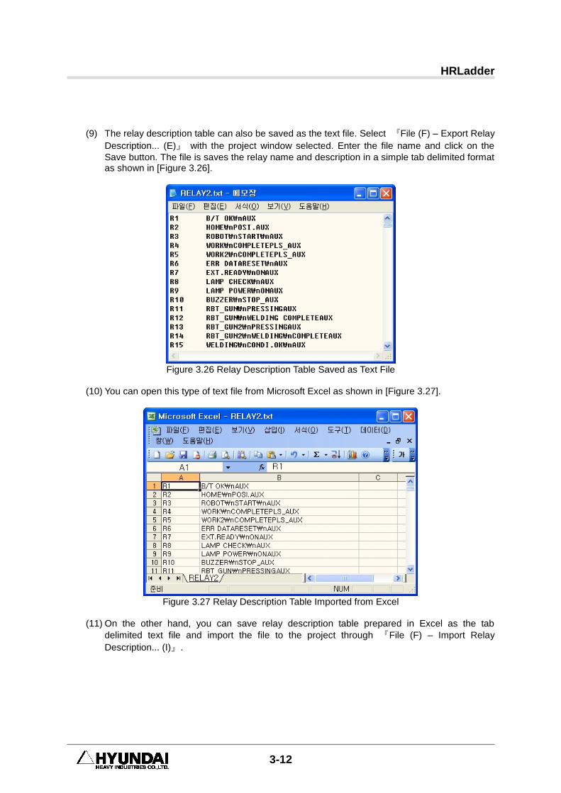
(9) The relay description table can also be saved as the text file. Select 『File (F) – Export Relay
Description... (E)』 with the project window selected. Enter the file name and click on the
Save button. The file is saves the relay name and description in a simple tab delimited format as shown in [Figure 3.26].
Figure 3.26 Relay Description Table Saved as Text File
(10) You can open this type of text file from Microsoft Excel as shown in [Figure 3.27].
Figure 3.27 Relay Description Table Imported from Excel
(11) On the other hand, you can save relay description table prepared in Excel as the tab
delimited text file and import the file to the project through 『File (F) – Import Relay
Description... (I)』.
3. Edit Ladder Diagram
3-13
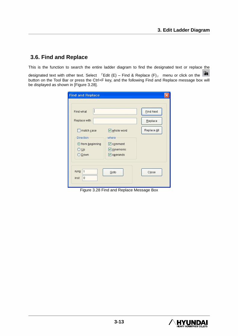
3.6. Find and Replace This is the function to search the entire ladder diagram to find the designated text or replace the
designated text with other text. Select 『Edit (E) – Find & Replace (F)』 menu or click on the
button on the Tool Bar or press the Ctrl+F key, and the following Find and Replace message box will be displayed as shown in [Figure 3.28].
Figure 3.28 Find and Replace Message Box
HRLadder
3-14
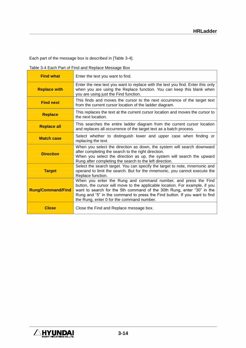
Each part of the message box is described in [Table 3-4]. Table 3-4 Each Part of Find and Replace Message Box
Find what Enter the text you want to find.
Replace with Enter the new text you want to replace with the text you find. Enter this only when you are using the Replace function. You can keep this blank when you are using just the Find function.
Find next This finds and moves the cursor to the next occurrence of the target text from the current cursor location of the ladder diagram.
Replace This replaces the text at the current cursor location and moves the cursor to the next location.
Replace all This searches the entire ladder diagram from the current cursor location and replaces all occurrence of the target text as a batch process.
Match case Select whether to distinguish lower and upper case when finding or replacing the text.
Direction
When you select the direction as down, the system will search downward after completing the search to the right direction. When you select the direction as up, the system will search the upward Rung after completing the search to the left direction.
Target Select the search target. You can specify the target to note, mnemonic and operand to limit the search. But for the mnemonic, you cannot execute the Replace function.
Rung/Command/Find
When you enter the Rung and command number, and press the Find button, the cursor will move to the applicable location. For example, if you want to search for the 5th command of the 30th Rung, enter “30” in the Rung and “5” in the command to press the Find button. If you want to find the Rung, enter 0 for the command number.
Close Close the Find and Replace message box.
3. Edit Ladder Diagram
3-15
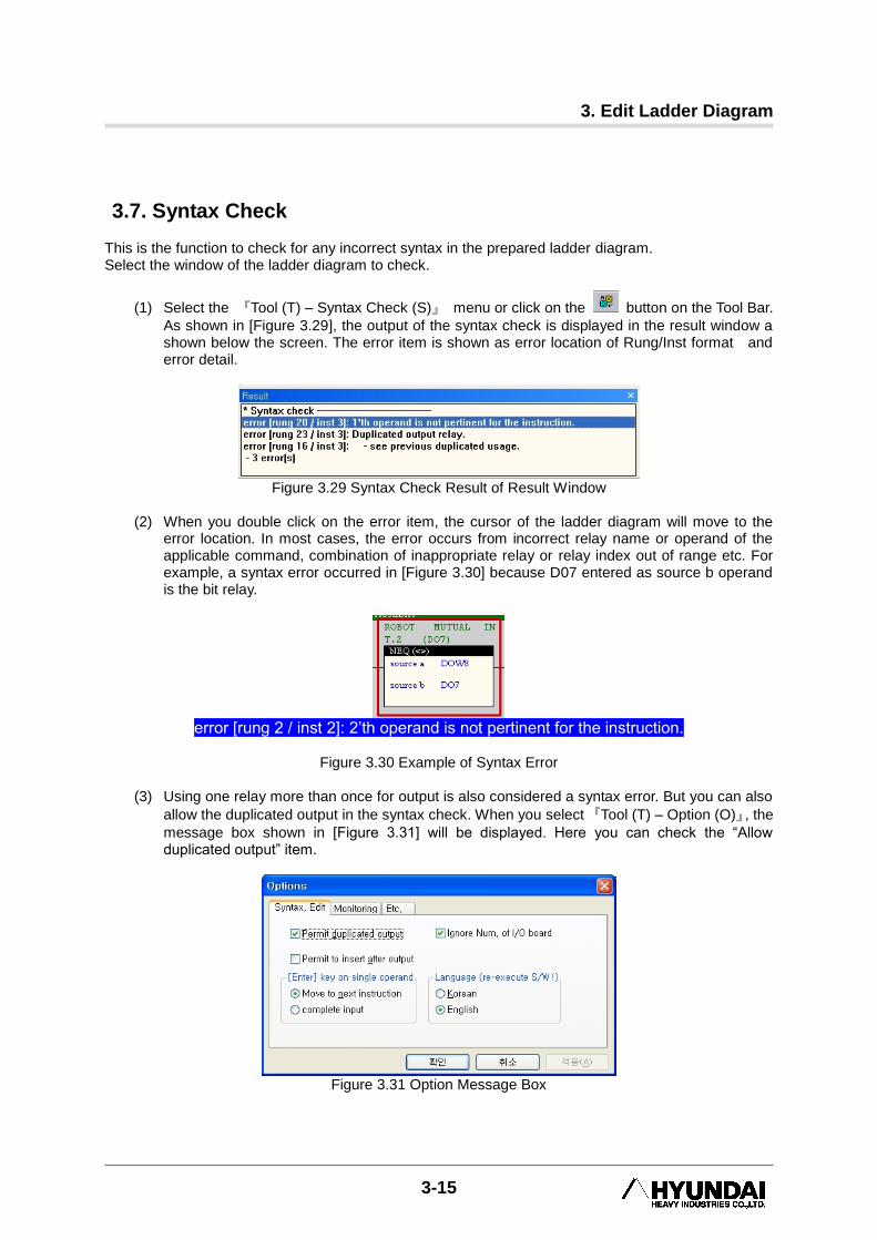
3.7. Syntax Check This is the function to check for any incorrect syntax in the prepared ladder diagram. Select the window of the ladder diagram to check.
(1) Select the 『Tool (T) – Syntax Check (S)』 menu or click on the button on the Tool Bar.
As shown in [Figure 3.29], the output of the syntax check is displayed in the result window a shown below the screen. The error item is shown as error location of Rung/Inst format and error detail.
Figure 3.29 Syntax Check Result of Result Window
(2) When you double click on the error item, the cursor of the ladder diagram will move to the
error location. In most cases, the error occurs from incorrect relay name or operand of the applicable command, combination of inappropriate relay or relay index out of range etc. For example, a syntax error occurred in [Figure 3.30] because D07 entered as source b operand is the bit relay.
error [rung 2 / inst 2]: 2‟th operand is not pertinent for the instruction.
Figure 3.30 Example of Syntax Error
(3) Using one relay more than once for output is also considered a syntax error. But you can also
allow the duplicated output in the syntax check. When you select 『Tool (T) – Option (O)』, the
message box shown in [Figure 3.31] will be displayed. Here you can check the “Allow duplicated output” item.
Figure 3.31 Option Message Box


4. Communication Setting
4-1
4. Communication Setting 4
Communication Setting
HRLadder
4-2
4.1. RS-232C Communication Setting
4.1.1. Hi5 Controller Side Setting
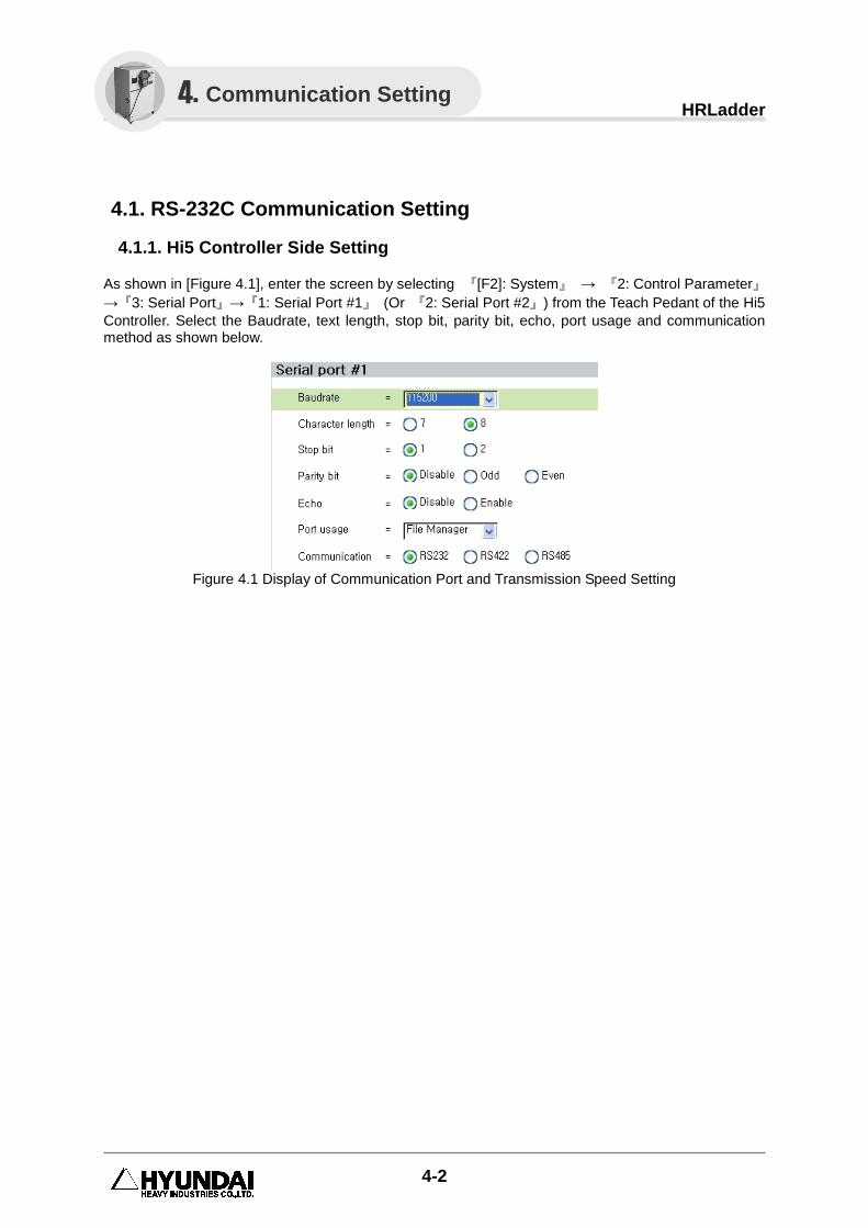
As shown in [Figure 4.1], enter the screen by selecting 『[F2]: System』 → 『2: Control Parameter』
→『3: Serial Port』→『1: Serial Port #1』 (Or 『2: Serial Port #2』) from the Teach Pedant of the Hi5
Controller. Select the Baudrate, text length, stop bit, parity bit, echo, port usage and communication method as shown below.
Figure 4.1 Display of Communication Port and Transmission Speed Setting
4. Communication Setting
4. Communication Setting
4-3
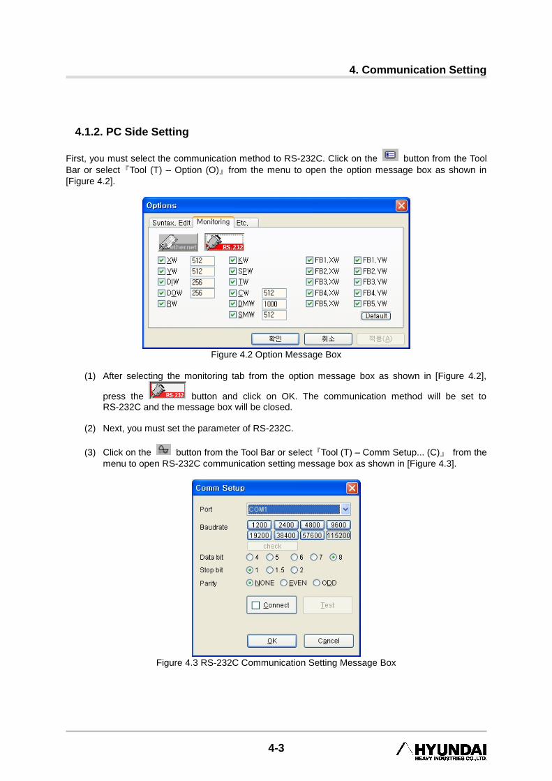
4.1.2. PC Side Setting
First, you must select the communication method to RS-232C. Click on the button from the Tool
Bar or select『Tool (T) – Option (O)』from the menu to open the option message box as shown in
[Figure 4.2].
Figure 4.2 Option Message Box
(1) After selecting the monitoring tab from the option message box as shown in [Figure 4.2],
press the button and click on OK. The communication method will be set to RS-232C and the message box will be closed.
(2) Next, you must set the parameter of RS-232C.
(3) Click on the button from the Tool Bar or select『Tool (T) – Comm Setup... (C)』 from the
menu to open RS-232C communication setting message box as shown in [Figure 4.3].
Figure 4.3 RS-232C Communication Setting Message Box
HRLadder
4-4
(4) Button in the RS-232 communication setting message box must be unchecked (That is, not connected) to make changes to the parameter. Therefore if this is checked, uncheck the box.
(5) Select the communication port that RS-232C cable is connected on the PC and set the same
baudrate as that of Hi5 Controller. Set the data bit, stop bit and parity as they are set up in Hi5 Controller as shown in [Figure 4.3].
(6) Click on OK to apply the setting and close the message box.
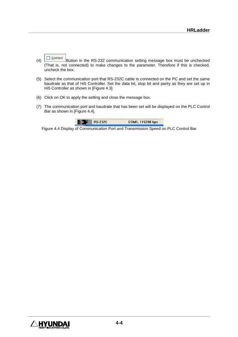
(7) The communication port and baudrate that has been set will be displayed on the PLC Control
Bar as shown in [Figure 4.4].
Figure 4.4 Display of Communication Port and Transmission Speed on PLC Control Bar
4. Communication Setting
4-5
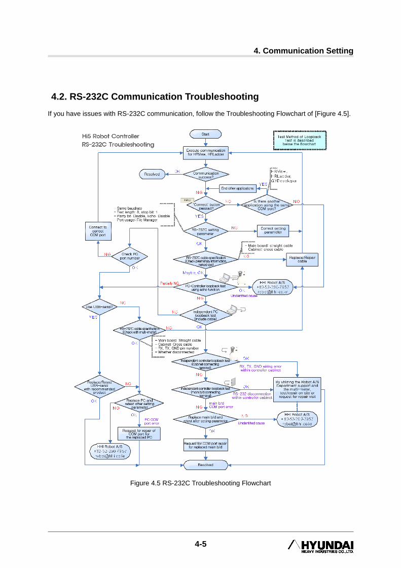
4.2. RS-232C Communication Troubleshooting If you have issues with RS-232C communication, follow the Troubleshooting Flowchart of [Figure 4.5].
Figure 4.5 RS-232C Troubleshooting Flowchart
HRLadder
4-6
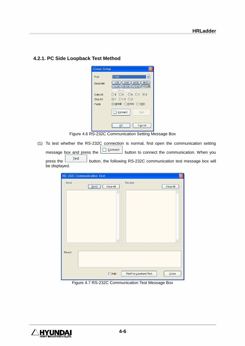
4.2.1. PC Side Loopback Test Method
Figure 4.6 RS-232C Communication Setting Message Box
(1) To test whether the RS-232C connection is normal, first open the communication setting
message box and press the button to connect the communication. When you
press the button, the following RS-232C communication test message box will be displayed.
Figure 4.7 RS-232C Communication Test Message Box
4. Communication Setting
4-7
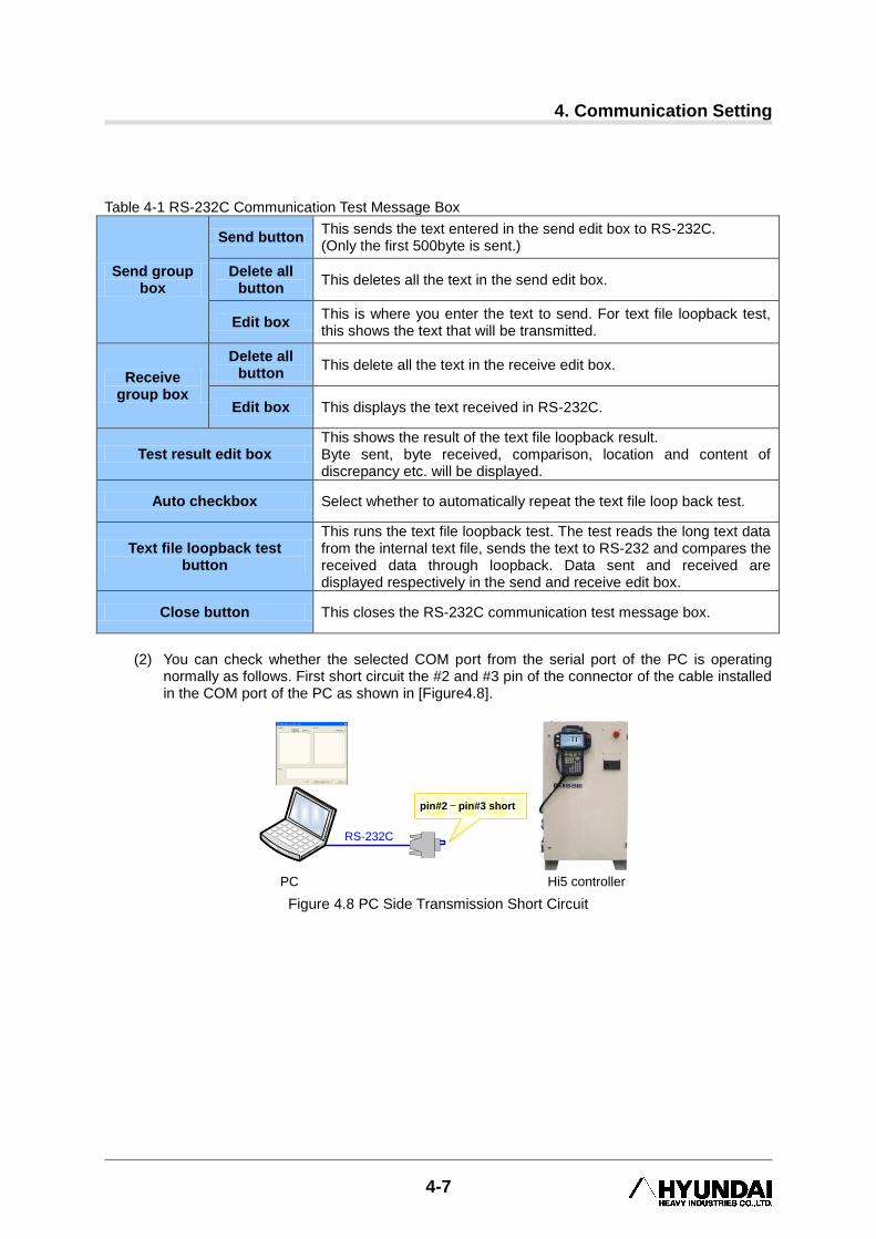
Table 4-1 RS-232C Communication Test Message Box
Send group box
Send button This sends the text entered in the send edit box to RS-232C. (Only the first 500byte is sent.)
Delete all button
This deletes all the text in the send edit box.
Edit box This is where you enter the text to send. For text file loopback test, this shows the text that will be transmitted.
Receive group box
Delete all button
This delete all the text in the receive edit box.
Edit box This displays the text received in RS-232C.
Test result edit box This shows the result of the text file loopback result. Byte sent, byte received, comparison, location and content of discrepancy etc. will be displayed.
Auto checkbox Select whether to automatically repeat the text file loop back test.
Text file loopback test button
This runs the text file loopback test. The test reads the long text data from the internal text file, sends the text to RS-232 and compares the received data through loopback. Data sent and received are displayed respectively in the send and receive edit box.
Close button This closes the RS-232C communication test message box.
(2) You can check whether the selected COM port from the serial port of the PC is operating
normally as follows. First short circuit the #2 and #3 pin of the connector of the cable installed in the COM port of the PC as shown in [Figure4.8].
Hi5 controllerPC
pin#2 – pin#3 short
RS-232C
Figure 4.8 PC Side Transmission Short Circuit

HRLadder
4-8
(3) When you press the Text File Loopback Test button, the internal text will be transmitted, and
the content will be shown in the edit box. The result is normal if it is shown as [Figure 4.9].
Figure 4.9 Text File Loopback Check
(4) The conclusions according to the test results are shown in [Table 4-2] as shown below.
Table 4-2 PC Side Text File Loopback Test Result
Result Conclusion (Estimated cause)
Data shown in the receive edit box is the same as the data sent and the test result shows 100% Matched!
Operation of COM port of PC is normal
When there is no data in the receive edit box.
- Cable disconnected. - Cable incorrectly connected to a different COM port on PC. - COM port error on PC - Pin #2 and #3 not short circuited. - USB-Serial product (If used) setting error or defect
The data in the receive edit box is different from the data sent and data is partially damaged.
- Partial defect in send/receive function of COM port of PC. Check for H/W error. - USB-Serial product (If used) error or poor performance

4. Communication Setting
4-9
(5) You can check whether the serial communication connection to the robot controller is normal
as follows. First connect the robot controller to the COM port of the PC through the serial communication cable as shown in [Figure 4.10].
Hi5 controllerPC
RS-232C
Figure 4.10 RS-232C Connection Between PC and Controller
(6) From the Teach Pendant of the robot controller, select 『[F2]: System』 → 『2: Control
Parameter』 → 『3: Serial Port』 → 『1: Serial Port #1』(Or, 『2: Serial Port #2』) screen
and set up so that the communication parameter aligns with the PC side, and set the “Echo” to <Enable> as shown in [Figure 4.11].
Figure 4.11 Set Serial Port “Echo” to <Enable>
(7) When you press the Text File Loopback Test Button and internal text file will be transmitted
and the details will be shown in the edit box. The conclusion based on the test result is shown in [Table 4-3] below.
HRLadder
4-10
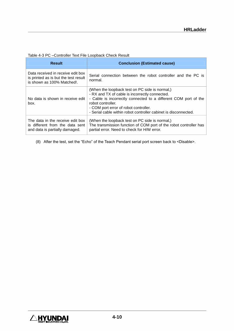
Table 4-3 PC –Controller Text File Loopback Check Result
Result Conclusion (Estimated cause)
Data received in receive edit box is printed as is but the test result is shown as 100% Matched!.
Serial connection between the robot controller and the PC is normal.
No data is shown in receive edit box.
(When the loopback test on PC side is normal,) - RX and TX of cable is incorrectly connected. - Cable is incorrectly connected to a different COM port of the robot controller. - COM port error of robot controller. - Serial cable within robot controller cabinet is disconnected.
The data in the receive edit box is different from the data sent and data is partially damaged.
(When the loopback test on PC side is normal,) The transmission function of COM port of the robot controller has partial error. Need to check for H/W error.
(8) After the test, set the “Echo” of the Teach Pendant serial port screen back to <Disable>.

4. Communication Setting
4-11
4.2.2. Controller Side Loopback Test Method
(1) From the Teach Pendant of the robot controller, select 『[F2]: System』 → 『2: Control
Parameter』 → 『3: Serial Port』 → 『1: Serial Port #1』(Or, 『2: Serial Port #2』) screen
and press the 『[F1]: Communication Test』 button.
(2) In accordance with the direction on the screen, short circuit the 2-3 pin of the RS-232C
terminal of the controller cabinet as shown in [Figure 4.12] A.)
(A) (B)
Figure 4.12 Controller Cabinet Side RS-232C Transmission Short Circuit
(3) If you see the message shown in [Figure 4.13] when you press the [ENTER] key, it is normal.
Figure 4.13 Normal Loopback Test Result
HRLadder
4-12
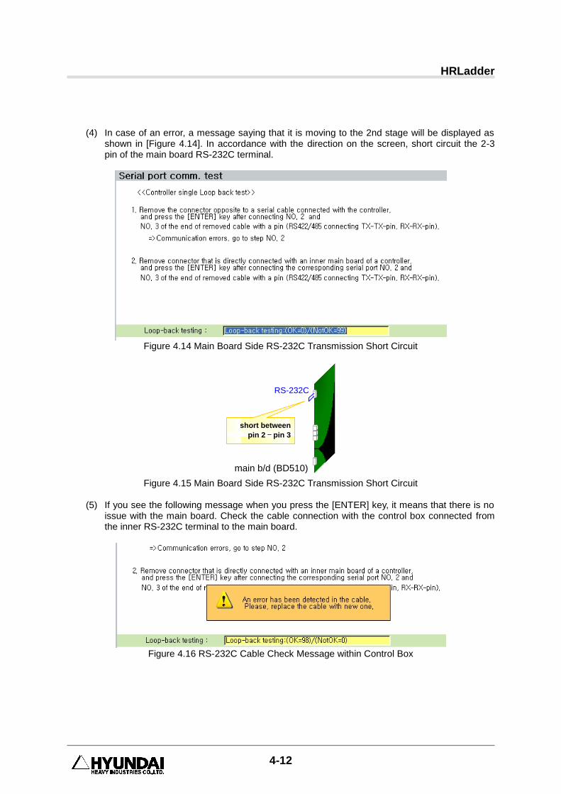
(4) In case of an error, a message saying that it is moving to the 2nd stage will be displayed as
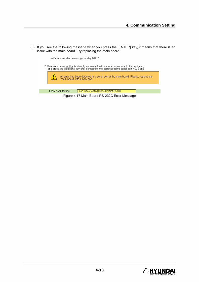
shown in [Figure 4.14]. In accordance with the direction on the screen, short circuit the 2-3 pin of the main board RS-232C terminal.
Figure 4.14 Main Board Side RS-232C Transmission Short Circuit
short between
pin 2 – pin 3
main b/d (BD510)
RS-232C
Figure 4.15 Main Board Side RS-232C Transmission Short Circuit
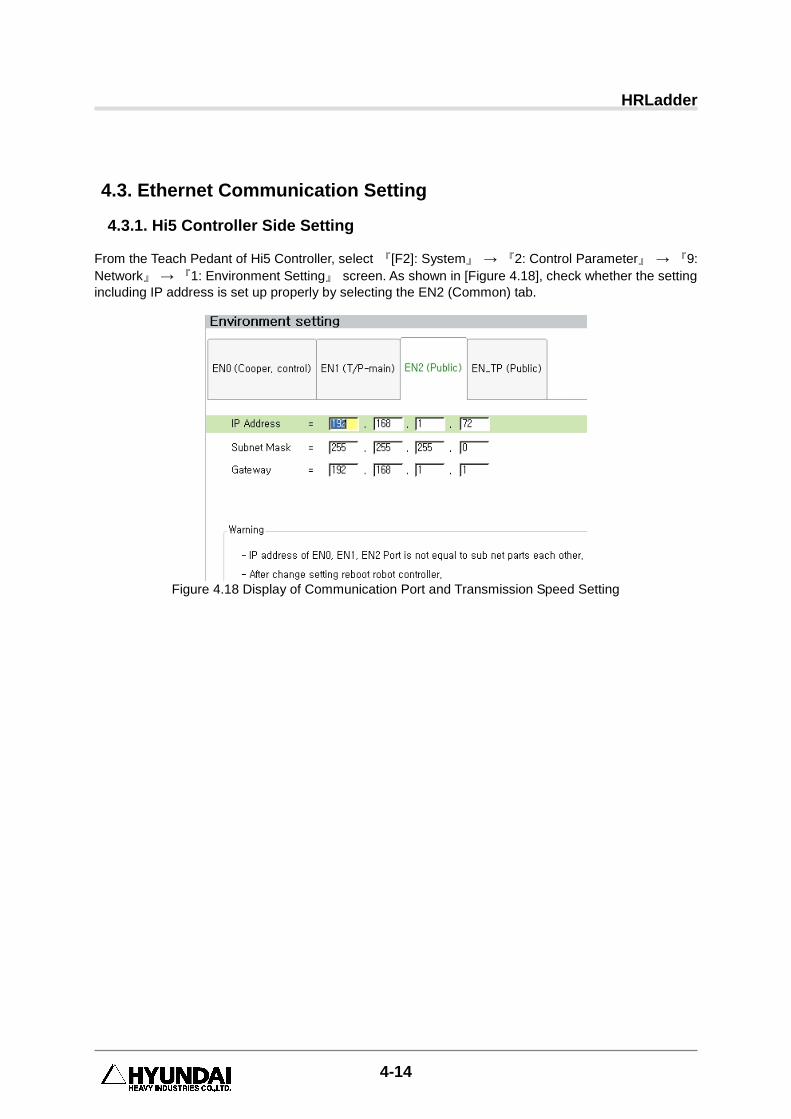
(5) If you see the following message when you press the [ENTER] key, it means that there is no
issue with the main board. Check the cable connection with the control box connected from the inner RS-232C terminal to the main board.
Figure 4.16 RS-232C Cable Check Message within Control Box
4. Communication Setting
4-13
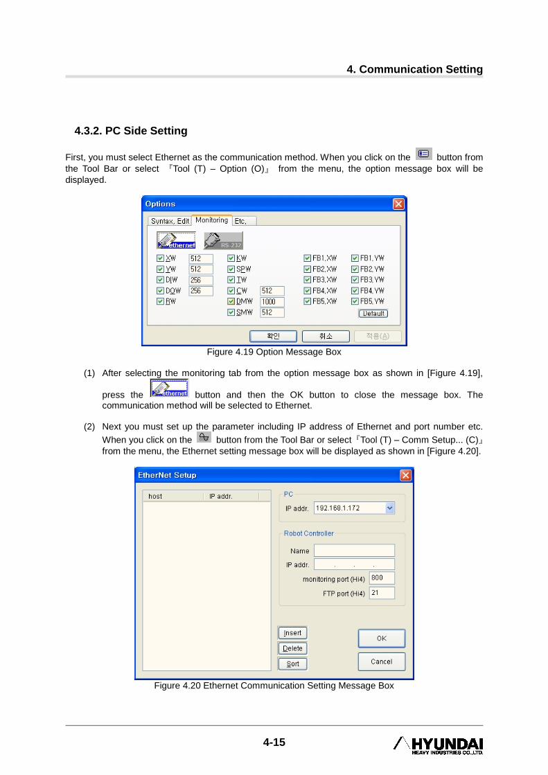
(6) If you see the following message when you press the [ENTER] key, it means that there is an
issue with the main board. Try replacing the main board.
Figure 4.17 Main Board RS-232C Error Message
HRLadder
4-14
4.3. Ethernet Communication Setting
4.3.1. Hi5 Controller Side Setting
From the Teach Pedant of Hi5 Controller, select 『[F2]: System』 → 『2: Control Parameter』 → 『9:
Network』 → 『1: Environment Setting』 screen. As shown in [Figure 4.18], check whether the setting
including IP address is set up properly by selecting the EN2 (Common) tab.
Figure 4.18 Display of Communication Port and Transmission Speed Setting
4. Communication Setting
4-15
4.3.2. PC Side Setting
First, you must select Ethernet as the communication method. When you click on the button from
the Tool Bar or select 『Tool (T) – Option (O)』 from the menu, the option message box will be
displayed.
Figure 4.19 Option Message Box
(1) After selecting the monitoring tab from the option message box as shown in [Figure 4.19],
press the button and then the OK button to close the message box. The communication method will be selected to Ethernet.
(2) Next you must set up the parameter including IP address of Ethernet and port number etc.
When you click on the button from the Tool Bar or select『Tool (T) – Comm Setup... (C)』
from the menu, the Ethernet setting message box will be displayed as shown in [Figure 4.20].
Figure 4.20 Ethernet Communication Setting Message Box
HRLadder
4-16
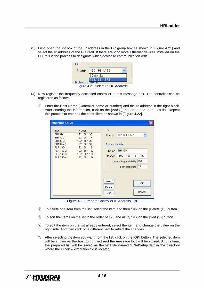
(3) First, open the list box of the IP address in the PC group box as shown in [Figure 4.21] and
select the IP address of the PC itself. If there are 2 or more Ethernet devices installed on the PC, this is the process to designate which device to communication with.
Figure 4.21 Select PC IP Address
(4) Now register the frequently accessed controller in this message box. The controller can be
registered as follows.
① Enter the Host Name (Controller name or number) and the IP address in the right block. After entering the information, click on the [Add (I)] button to add to the left list. Repeat this process to enter all the controllers as shown in [Figure 4.22].
Figure 4.22 Prepare Controller IP Address List
② To delete one item from the list, select the item and then click on the [Delete (D)] button.
③ To sort the items on the list in the order of 123 and ABC, click on the [Sort (S)] button.
④ To edit the item on the list already entered, select the item and change the value on the right side. And then click on a different item to reflect the changes.
⑤ After selecting the item you want from the list, click on the [OK] button. The selected item will be shown as the host to connect and the message box will be closed. At this time, the prepared list will be saved as the text file named “ENetSetup.dat” in the directory where the HRView execution file is located.
4. Communication Setting
4-17
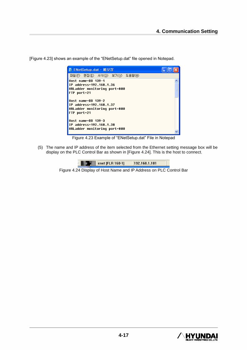
[Figure 4.23] shows an example of the “ENetSetup.dat” file opened in Notepad.
Figure 4.23 Example of “ENetSetup.dat” File in Notepad
(5) The name and IP address of the item selected from the Ethernet setting message box will be
display on the PLC Control Bar as shown in [Figure 4.24]. This is the host to connect.
Figure 4.24 Display of Host Name and IP Address on PLC Control Bar
HRLadder
4-18
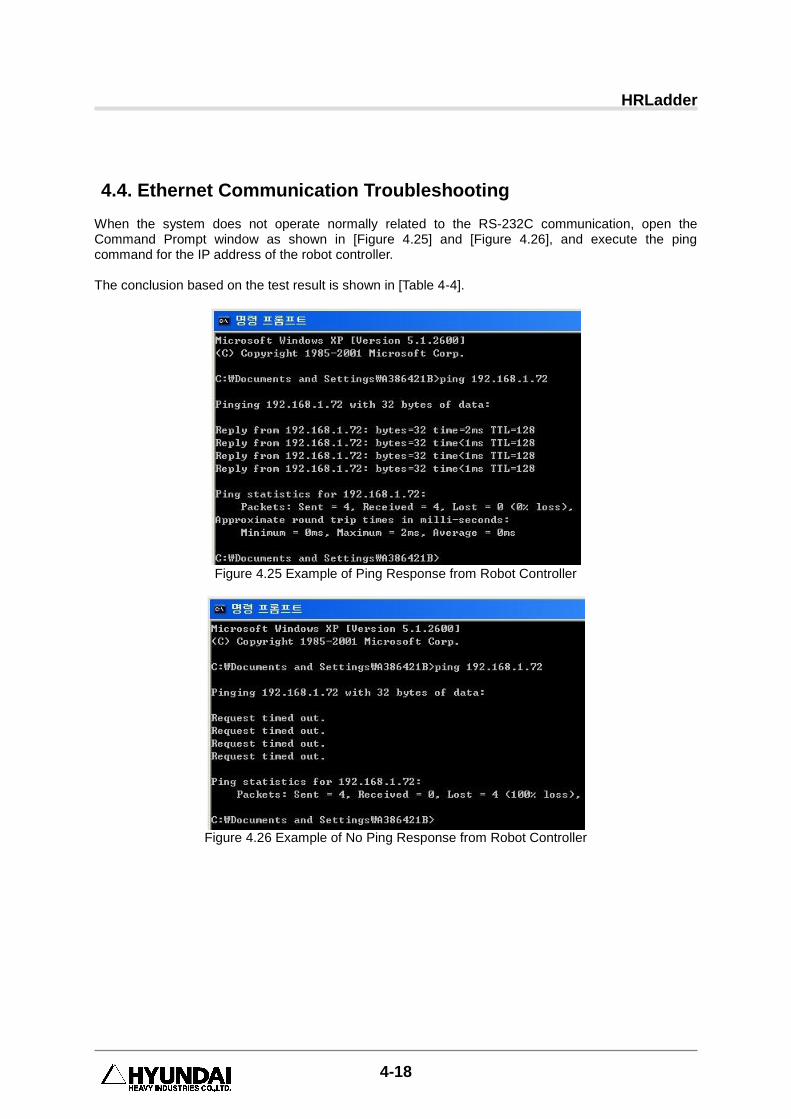
4.4. Ethernet Communication Troubleshooting When the system does not operate normally related to the RS-232C communication, open the Command Prompt window as shown in [Figure 4.25] and [Figure 4.26], and execute the ping command for the IP address of the robot controller. The conclusion based on the test result is shown in [Table 4-4].
Figure 4.25 Example of Ping Response from Robot Controller
Figure 4.26 Example of No Ping Response from Robot Controller
4. Communication Setting
4-19
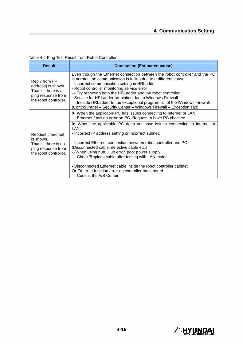
Table 4-4 Ping Test Result from Robot Controller
Result Conclusion (Estimated cause)
Reply from {IP address} is shown. That is, there is a ping response from the robot controller.
Even though the Ethernet connection between the robot controller and the PC is normal, the communication is failing due to a different cause. - Incorrect communication setting in HRLadder - Robot controller monitoring service error → Try rebooting both the HRLadder and the robot controller. - Service for HRLadder prohibited due to Windows Firewall → Include HRLadder to the exceptional program list of the Windows Firewall. (Control Panel – Security Center – Windows Firewall – Exception Tab)
Request timed out is shown. That is, there is no ping response from the robot controller.
▶ When the applicable PC has issues connecting to Internet or LAN: → Ethernet function error on PC. Request to have PC checked
▶ When the applicable PC does not have issues connecting to Internet or LAN: - Incorrect IP address setting or incorrect subnet. - Incorrect Ethernet connection between robot controller and PC. (Disconnected cable, defective cable etc.) - (When using hub) Hub error, poor power supply → Check/Replace cable after testing with LAN tester. - Disconnected Ethernet cable inside the robot controller cabinet Or Ethernet function error on controller main board → Consult the A/S Center


5. File Upload/Download
5-1
5. File Upload/Download
5 File Upload/ Download
HRLadder
5-2
5.1. Ladder file
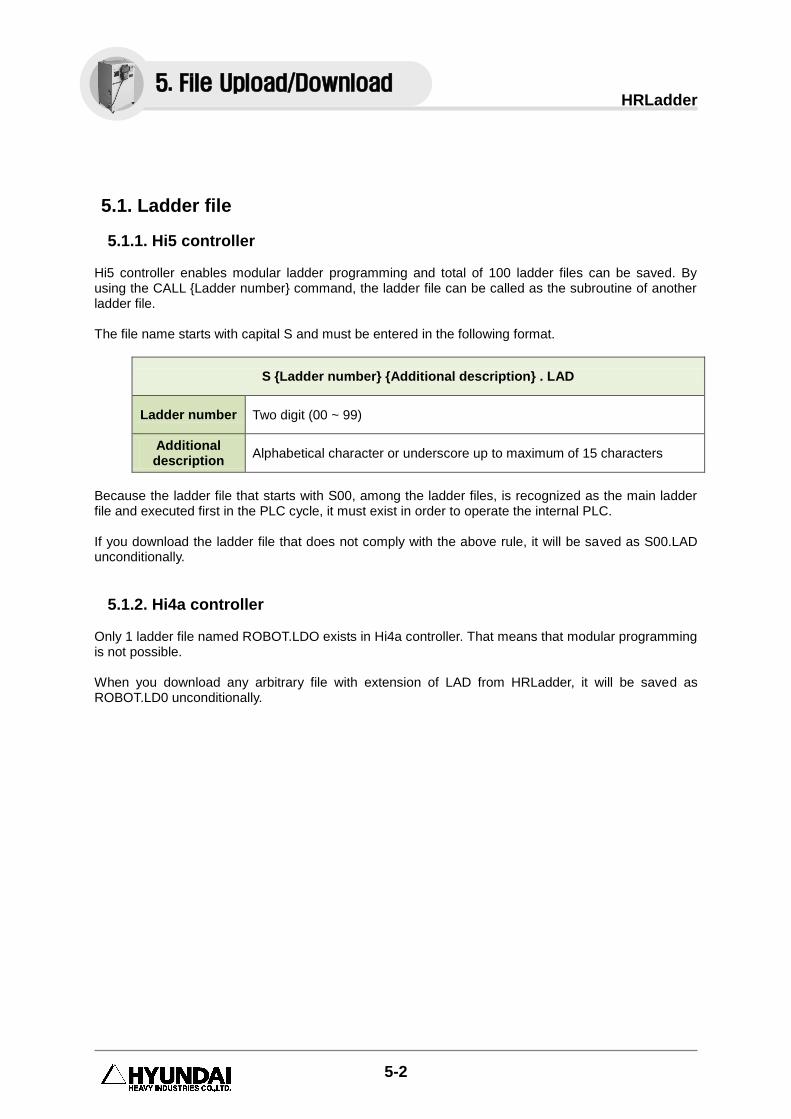
5.1.1. Hi5 controller Hi5 controller enables modular ladder programming and total of 100 ladder files can be saved. By using the CALL {Ladder number} command, the ladder file can be called as the subroutine of another ladder file. The file name starts with capital S and must be entered in the following format.
S {Ladder number} {Additional description} . LAD
Ladder number Two digit (00 ~ 99)
Additional description
Alphabetical character or underscore up to maximum of 15 characters
Because the ladder file that starts with S00, among the ladder files, is recognized as the main ladder file and executed first in the PLC cycle, it must exist in order to operate the internal PLC. If you download the ladder file that does not comply with the above rule, it will be saved as S00.LAD unconditionally.
5.1.2. Hi4a controller Only 1 ladder file named ROBOT.LDO exists in Hi4a controller. That means that modular programming is not possible. When you download any arbitrary file with extension of LAD from HRLadder, it will be saved as ROBOT.LD0 unconditionally.
5. File Upload/Download
5. File Upload/Download
5-3
5.2. Download When downloading the ladder diagram, first HRLadder and the internal PLC must be connected in
“online” condition. Check the button on the PLC Control Bar. If not “online”, press the button to switch to “online” condition.
5.2.1. Download selected ladder window This is the function to download the ladder diagram after editing while the window is currently open. If not for modular ladder programming, use this function.
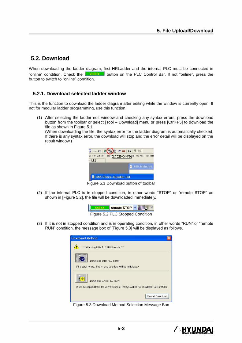
(1) After selecting the ladder edit window and checking any syntax errors, press the download button from the toolbar or select [Tool – Download] menu or press [Ctrl+F5] to download the file as shown in Figure 5.1. (When downloading the file, the syntax error for the ladder diagram is automatically checked. If there is any syntax error, the download will stop and the error detail will be displayed on the result window.)
Figure 5.1 Download button of toolbar
(2) If the internal PLC is in stopped condition, in other words “STOP” or “remote STOP” as
shown in [Figure 5.2], the file will be downloaded immediately.
Figure 5.2 PLC Stopped Condition
(3) If it is not in stopped condition and is in operating condition, in other words “RUN” or “remote
RUN” condition, the message box of [Figure 5.3] will be displayed as follows.
Figure 5.3 Download Method Selection Message Box
HRLadder
5-4
(4) If you select 『Download after PLC stops』, it will automatically switch the condition of the
internal PLC from “remote RUN” to “remote STOP” and then start the download. (If the internal PLC is in “RUN” condition, an error message will be displayed because it cannot be switched to remote mode.) Because the internal PLC is stopped, the downloaded ladder task will start the operation with all the setting initialized including the output contact point, timer and counter etc.
! If the signal is disconnected, be careful of any potential object falling.
(5) When you select 『Download while PLC is running』, the file will be downloaded while the
PLC is operating. But, the newly downloaded PLC ladder file will be applied from the next cycle of the PLC.
!
Settings, including output contact point, timer and counter, are not initialized. Therefore, you must be careful to check whether the residual ladder values have any issue with the edited ladder logic structure.
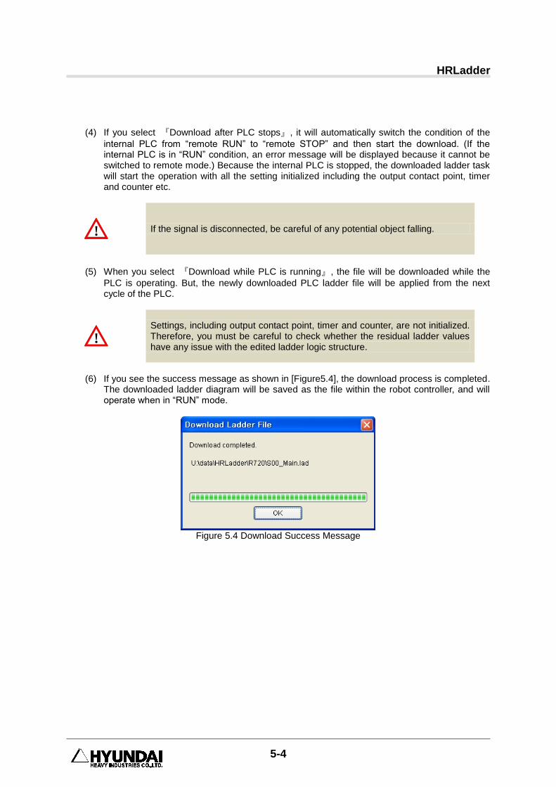
(6) If you see the success message as shown in [Figure5.4], the download process is completed.
The downloaded ladder diagram will be saved as the file within the robot controller, and will operate when in “RUN” mode.
Figure 5.4 Download Success Message
5. File Upload/Download
5-5
5.2.2. Download in Workspace This function is for modular ladder programming in Hi5 controller. (Do not use this for Hi4a.)
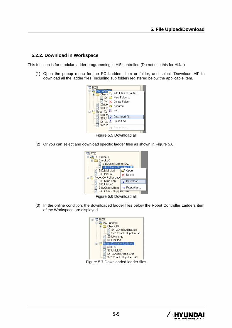
(1) Open the popup menu for the PC Ladders item or folder, and select “Download All” to download all the ladder files (Including sub folder) registered below the applicable item.
Figure 5.5 Download all
(2) Or you can select and download specific ladder files as shown in Figure 5.6.
Figure 5.6 Download all
(3) In the online condition, the downloaded ladder files below the Robot Controller Ladders item
of the Workspace are displayed.
Figure 5.7 Downloaded ladder files

HRLadder
5-6
5.3. Upload This is the function to receive and open the internal PLC ladder file (ROBOT_00.LAD) of the robot controller in HRLadder. When uploading the ladder diagram, first the HRLadder and internal PLC must be in online condition as shown in [Figure5.5]. If not, switch to “online”.
Figure 5.8 Confirmation of Online Condition
5.3.1. Upload main program in ladder window This function uploads the main ladder program of robot controller (S00.LAD for Hi5 and ROBOT.LD0 for Hi4a) to the PC and opens the ladder edit window.
(1) Click on the Upload button on the Tool Bar as shown in Figure 5.6 or use the 『Tool (T) –
Upload(U)』 menu or use the function key [Ctrl+F6] to upload the file.
Figure 5.9 Upload Button on Tool Bar
(2) When you see the success message, it means that the upload has been successfully
completed. The uploaded ladder diagram will be opened as “Noname.lad” within HRLadder.
Figure 5.10 Upload Success Message
5. File Upload/Download
5-7
5.3.2. Upload from Workspace This function is for modular ladder programming of Hi5 controller. (Do not use this for Hi4a.)
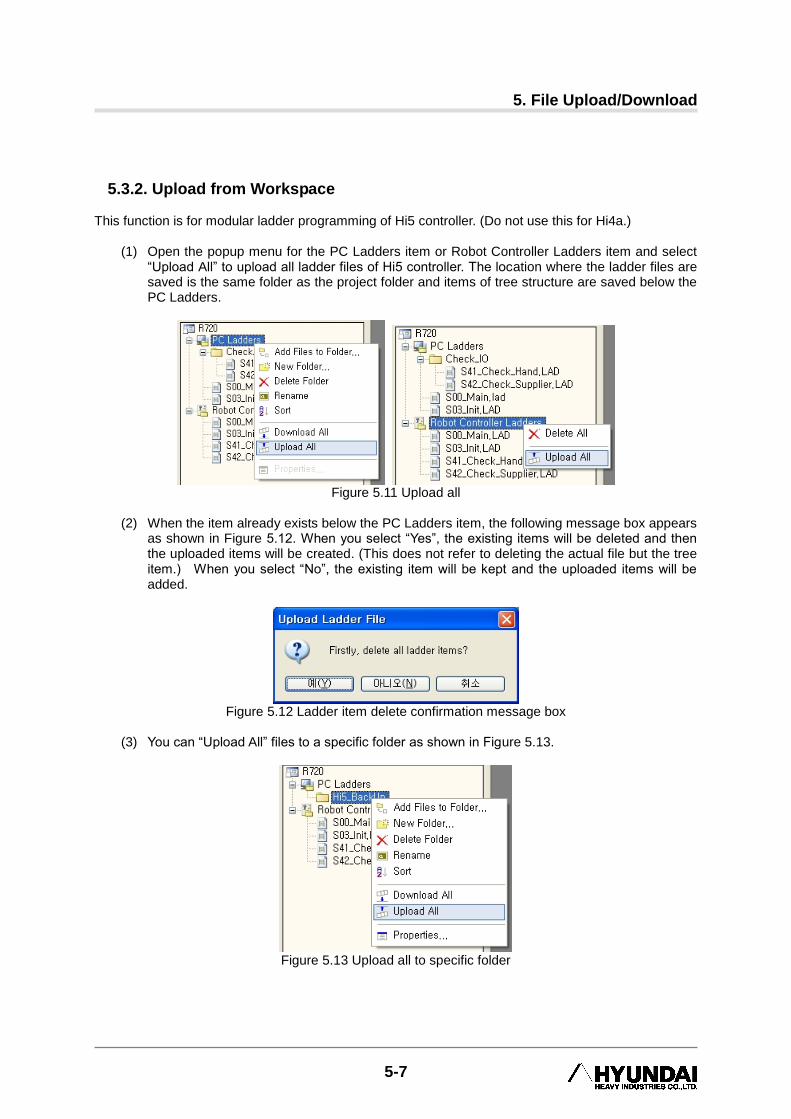
(1) Open the popup menu for the PC Ladders item or Robot Controller Ladders item and select “Upload All” to upload all ladder files of Hi5 controller. The location where the ladder files are saved is the same folder as the project folder and items of tree structure are saved below the PC Ladders.
Figure 5.11 Upload all
(2) When the item already exists below the PC Ladders item, the following message box appears
as shown in Figure 5.12. When you select “Yes”, the existing items will be deleted and then the uploaded items will be created. (This does not refer to deleting the actual file but the tree item.) When you select “No”, the existing item will be kept and the uploaded items will be added.
Figure 5.12 Ladder item delete confirmation message box
(3) You can “Upload All” files to a specific folder as shown in Figure 5.13.
Figure 5.13 Upload all to specific folder
HRLadder
5-8
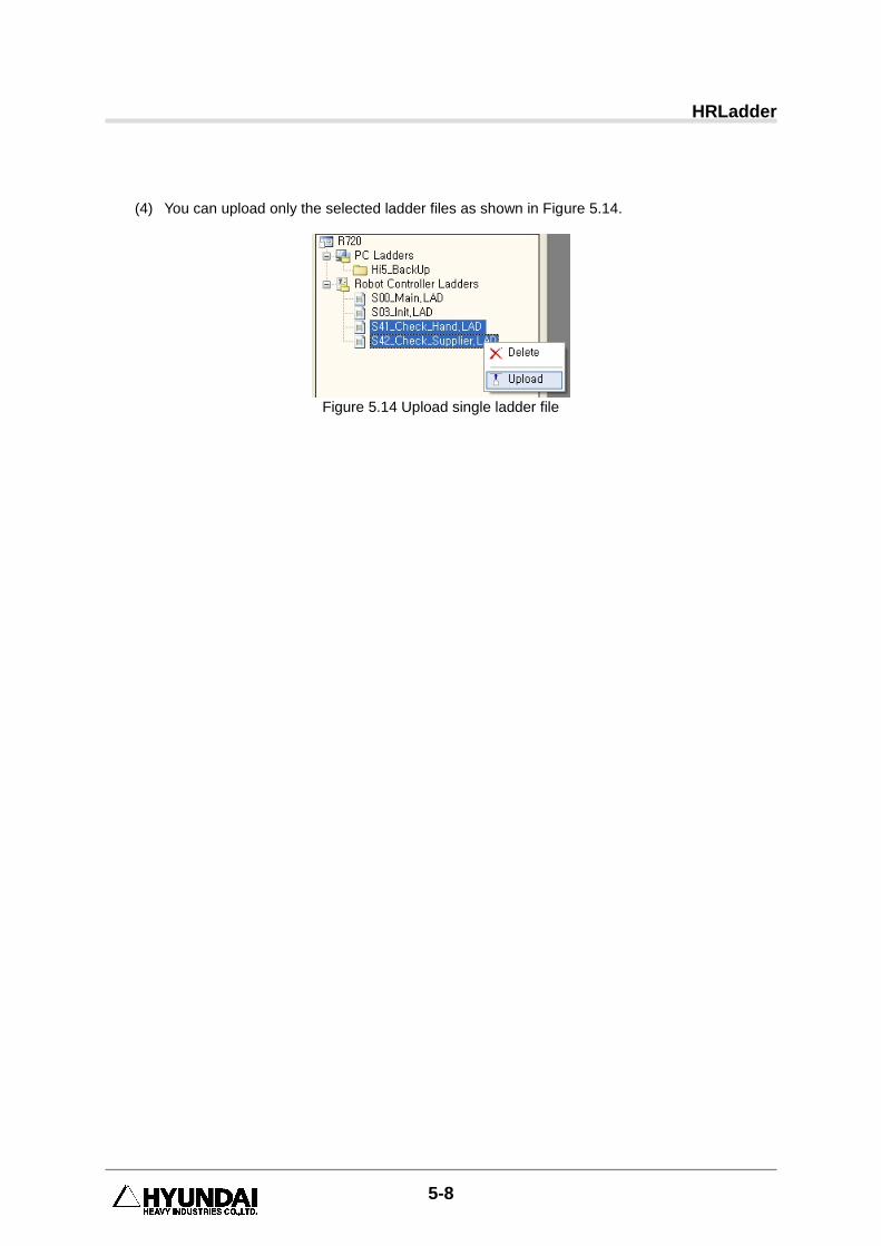
(4) You can upload only the selected ladder files as shown in Figure 5.14.
Figure 5.14 Upload single ladder file

6. Monitoring
6-1
6. Monitoring
6 Monitoring
HRLadder
6-2
6.1. PLC Monitoring This is the function to use HRLadder to monitor the current relay value condition of the internal PLC of the robot controller.
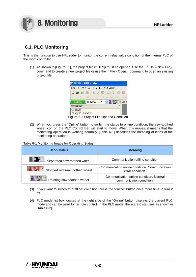
(1) As shown in [Figure6.1], the project file (*.HlPrj) must be opened. Use the 『File – New File』
command to create a new project file or use the 『File - Open』 command to open an existing
project file.
Figure 6.1 Project File Opened Condition
(2) When you press the “Online” button to switch the status to online condition, the saw-toothed
wheel icon on the PLC Control Bar will start to move. When this moves, it means that the monitoring operation is working normally. [Table 6-1] describes the meaning of icons of the monitoring operation.
Table 6-1 Monitoring Image for Operating Status
Icon status Meaning
Separated saw-toothed wheel Communication offline condition
Stopped red saw-toothed wheel Communication online condition. Communication
error condition.
Rotating saw-toothed wheel Communication online condition. Normal
communication condition.
(3) If you want to switch to “Offline” condition, press the “online” button once more time to turn it
off.
(4) PLC mode list box located at the right side of the “Online” button displays the current PLC mode and can be used for remote control. In the PLC mode, there are 6 statuses as shown in [Table 6-2].
6. Monitoring
6. Monitoring
6-3
Table 6-2 Status of All PLC List Box
PLC Mode Meaning
STOP Ladder operation stopped. Can switch mode only with controller T/P.
RUN Ladder operation running. Can switch mode only with controller T/P.
Remote STOP Ladder operation stopped. Can switch mode remotely with Remote-RUN from HRLadder
Remote RUN Ladder operation running. Can switch mode remotely with Remote –STOP from HRLadder
PLC OFF Internal PLC turned off. (H4a Controller dip s/w #5 OFF or Hi5 Controller application condition PLC OFF)
NO LAD No ladder diagram in internal PLC
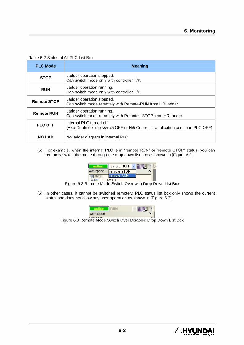
(5) For example, when the internal PLC is in “remote RUN” or “remote STOP” status, you can
remotely switch the mode through the drop down list box as shown in [Figure 6.2].
Figure 6.2 Remote Mode Switch Over with Drop Down List Box
(6) In other cases, it cannot be switched remotely. PLC status list box only shows the current
status and does not allow any user operation as shown in [Figure 6.3].
Figure 6.3 Remote Mode Switch Over Disabled Drop Down List Box
HRLadder
6-4
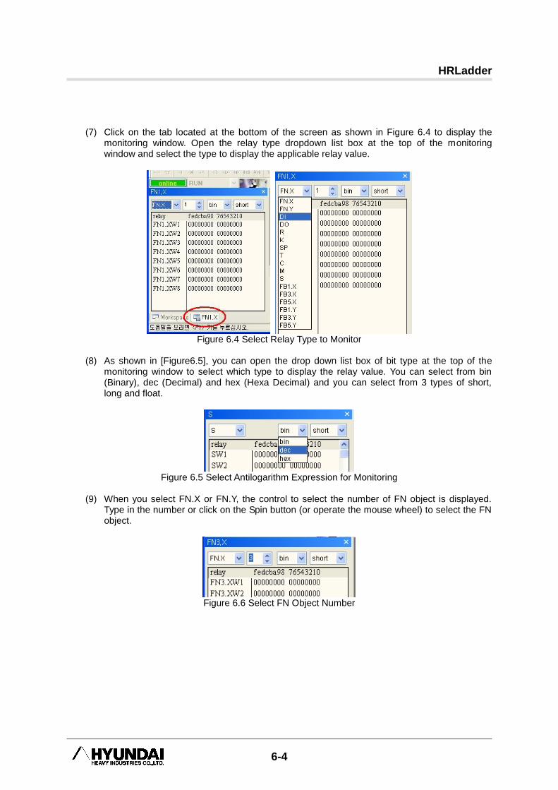
(7) Click on the tab located at the bottom of the screen as shown in Figure 6.4 to display the
monitoring window. Open the relay type dropdown list box at the top of the monitoring window and select the type to display the applicable relay value.
Figure 6.4 Select Relay Type to Monitor
(8) As shown in [Figure6.5], you can open the drop down list box of bit type at the top of the
monitoring window to select which type to display the relay value. You can select from bin (Binary), dec (Decimal) and hex (Hexa Decimal) and you can select from 3 types of short, long and float.
Figure 6.5 Select Antilogarithm Expression for Monitoring
(9) When you select FN.X or FN.Y, the control to select the number of FN object is displayed.
Type in the number or click on the Spin button (or operate the mouse wheel) to select the FN object.
Figure 6.6 Select FN Object Number
6. Monitoring
6-5
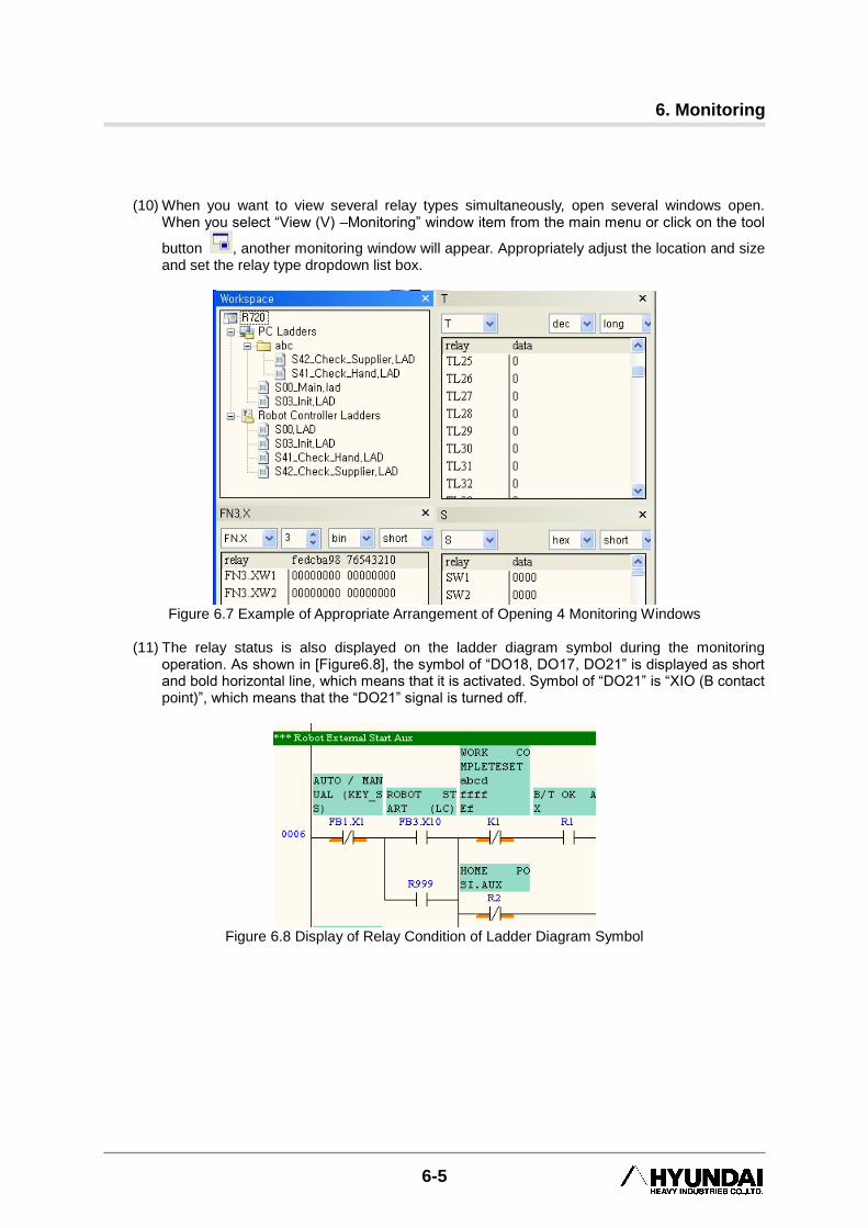
(10) When you want to view several relay types simultaneously, open several windows open.
When you select “View (V) –Monitoring” window item from the main menu or click on the tool
button , another monitoring window will appear. Appropriately adjust the location and size and set the relay type dropdown list box.
Figure 6.7 Example of Appropriate Arrangement of Opening 4 Monitoring Windows
(11) The relay status is also displayed on the ladder diagram symbol during the monitoring
operation. As shown in [Figure6.8], the symbol of “DO18, DO17, DO21” is displayed as short and bold horizontal line, which means that it is activated. Symbol of “DO21” is “XIO (B contact point)”, which means that the “DO21” signal is turned off.
Figure 6.8 Display of Relay Condition of Ladder Diagram Symbol
HRLadder
6-6
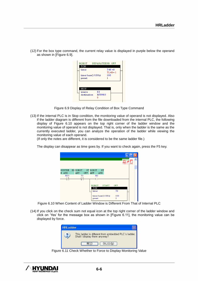
(12) For the box type command, the current relay value is displayed in purple below the operand as shown in [Figure 6.9].
Figure 6.9 Display of Relay Condition of Box Type Command
(13) If the internal PLC is in Stop condition, the monitoring value of operand is not displayed. Also if the ladder diagram is different from the file downloaded from the internal PLC, the following display of Figure 6.10 appears on the top right corner of the ladder window and the monitoring value of operand is not displayed. That is, only when the ladder is the same as the currently executed ladder, you can analyze the operation of the ladder while viewing the monitoring value of each operand. (If only the notes are different, it is considered to be the same ladder file.)
The display can disappear as time goes by. If you want to check again, press the F5 key.
Figure 6.10 When Content of Ladder Window is Different From That of Internal PLC
(14) If you click on the check sum not equal icon at the top right corner of the ladder window and
click on „Yes‟ for the message box as shown in [Figure 6.11], the monitoring value can be displayed by force.
Figure 6.11 Check Whether to Force to Display Monitoring Value
6. Monitoring
6-7
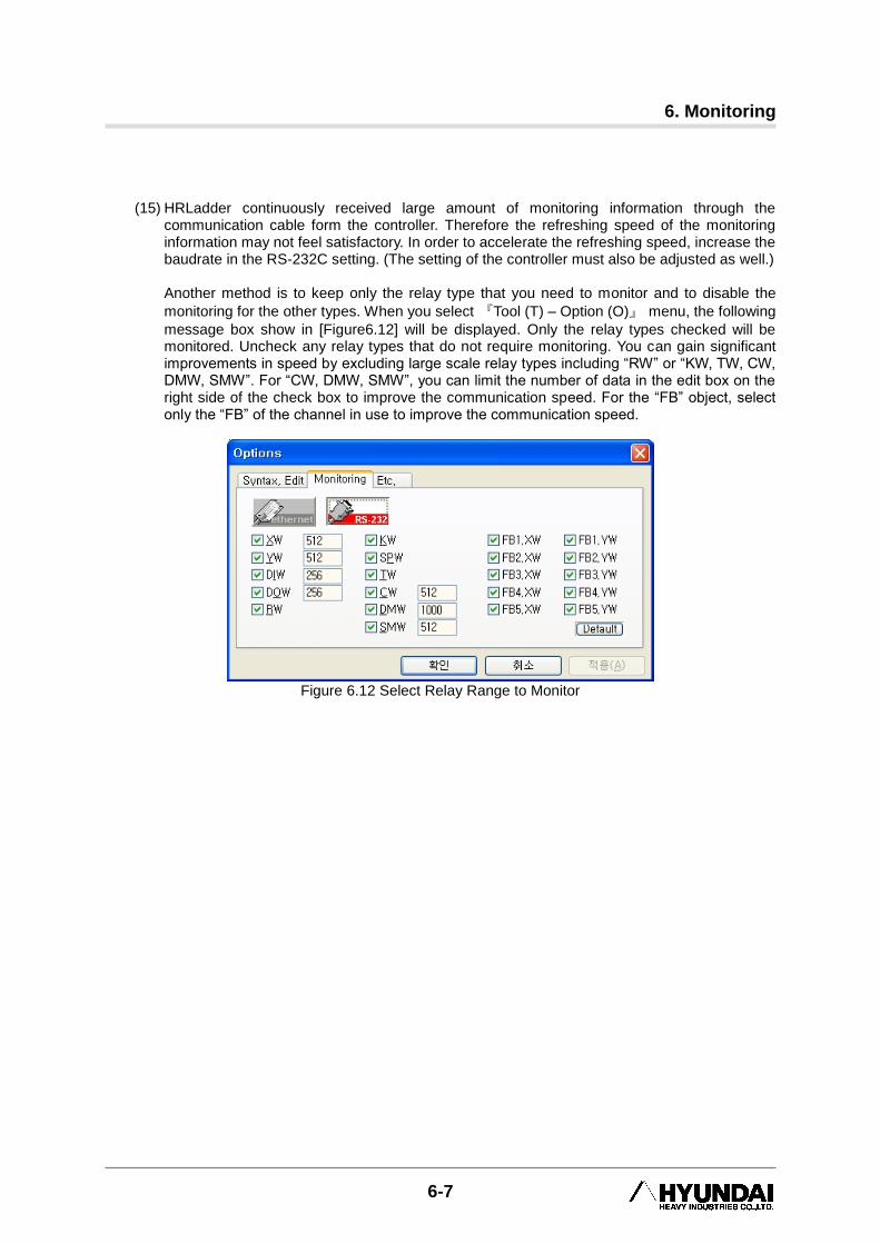
(15) HRLadder continuously received large amount of monitoring information through the
communication cable form the controller. Therefore the refreshing speed of the monitoring information may not feel satisfactory. In order to accelerate the refreshing speed, increase the baudrate in the RS-232C setting. (The setting of the controller must also be adjusted as well.)
Another method is to keep only the relay type that you need to monitor and to disable the
monitoring for the other types. When you select 『Tool (T) – Option (O)』 menu, the following
message box show in [Figure6.12] will be displayed. Only the relay types checked will be monitored. Uncheck any relay types that do not require monitoring. You can gain significant improvements in speed by excluding large scale relay types including “RW” or “KW, TW, CW, DMW, SMW”. For “CW, DMW, SMW”, you can limit the number of data in the edit box on the right side of the check box to improve the communication speed. For the “FB” object, select only the “FB” of the channel in use to improve the communication speed.
Figure 6.12 Select Relay Range to Monitor
HRLadder
6-8
6.2. Reset All Relays Reset All Relays function is the function to initialize the relay values of all the internal PLCs in HRLadder to “0”. To use this function, the following conditions must be satisfied.
(1) Project file (*.hpp) must be opened and in “ONLINE” status.
(2) Internal PLC must be turned on and in “STOP”, “remote STOP” or “NO LAD (No ladder file)” condition.
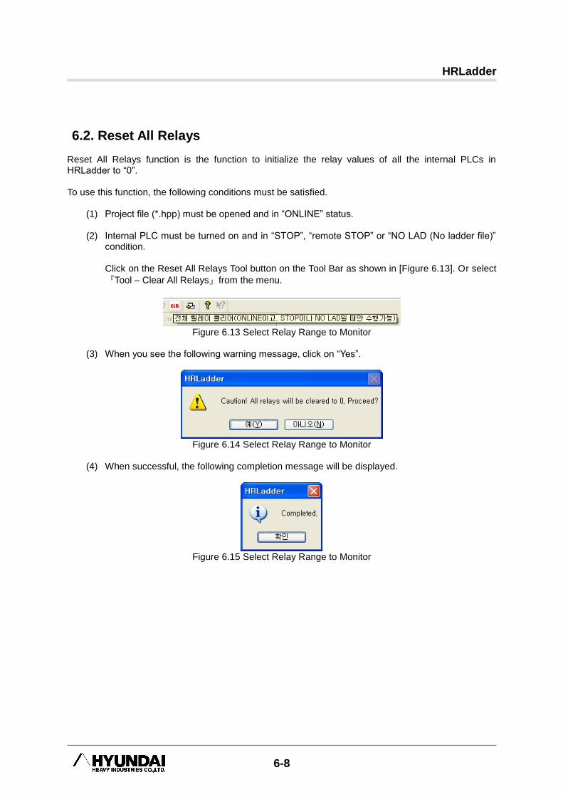
Click on the Reset All Relays Tool button on the Tool Bar as shown in [Figure 6.13]. Or select
『Tool – Clear All Relays』from the menu.
Figure 6.13 Select Relay Range to Monitor
(3) When you see the following warning message, click on “Yes”.
Figure 6.14 Select Relay Range to Monitor
(4) When successful, the following completion message will be displayed.
Figure 6.15 Select Relay Range to Monitor
6. Monitoring
6-9
6.3. Manual Output
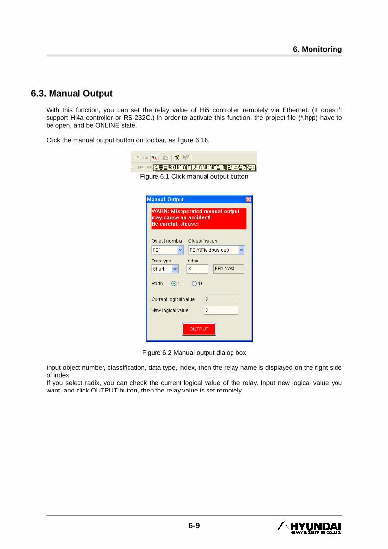
With this function, you can set the relay value of Hi5 controller remotely via Ethernet. (It doesn‟t support Hi4a controller or RS-232C.) In order to activate this function, the project file (*.hpp) have to be open, and be ONLINE state. Click the manual output button on toolbar, as figure 6.16.
Figure 6.1 Click manual output button
Figure 6.2 Manual output dialog box Input object number, classification, data type, index, then the relay name is displayed on the right side of index. If you select radix, you can check the current logical value of the relay. Input new logical value you want, and click OUTPUT button, then the relay value is set remotely.
HRLadder
6-10
6.4. Status Bar Information
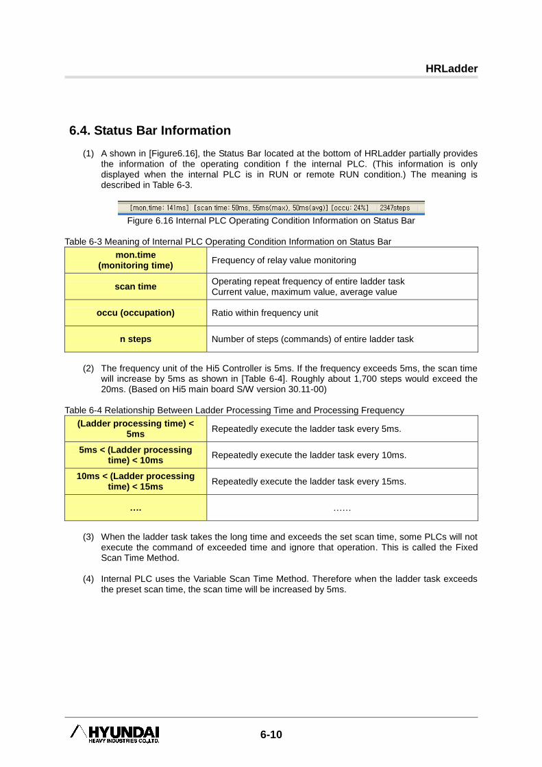
(1) A shown in [Figure6.16], the Status Bar located at the bottom of HRLadder partially provides the information of the operating condition f the internal PLC. (This information is only displayed when the internal PLC is in RUN or remote RUN condition.) The meaning is described in Table 6-3.
Figure 6.16 Internal PLC Operating Condition Information on Status Bar
Table 6-3 Meaning of Internal PLC Operating Condition Information on Status Bar
mon.time (monitoring time)
Frequency of relay value monitoring
scan time Operating repeat frequency of entire ladder task Current value, maximum value, average value
occu (occupation) Ratio within frequency unit
n steps Number of steps (commands) of entire ladder task
(2) The frequency unit of the Hi5 Controller is 5ms. If the frequency exceeds 5ms, the scan time
will increase by 5ms as shown in [Table 6-4]. Roughly about 1,700 steps would exceed the 20ms. (Based on Hi5 main board S/W version 30.11-00)
Table 6-4 Relationship Between Ladder Processing Time and Processing Frequency
(Ladder processing time) < 5ms
Repeatedly execute the ladder task every 5ms.
5ms < (Ladder processing time) < 10ms
Repeatedly execute the ladder task every 10ms.
10ms < (Ladder processing time) < 15ms
Repeatedly execute the ladder task every 15ms.
…. ……
(3) When the ladder task takes the long time and exceeds the set scan time, some PLCs will not
execute the command of exceeded time and ignore that operation. This is called the Fixed Scan Time Method.
(4) Internal PLC uses the Variable Scan Time Method. Therefore when the ladder task exceeds
the preset scan time, the scan time will be increased by 5ms.
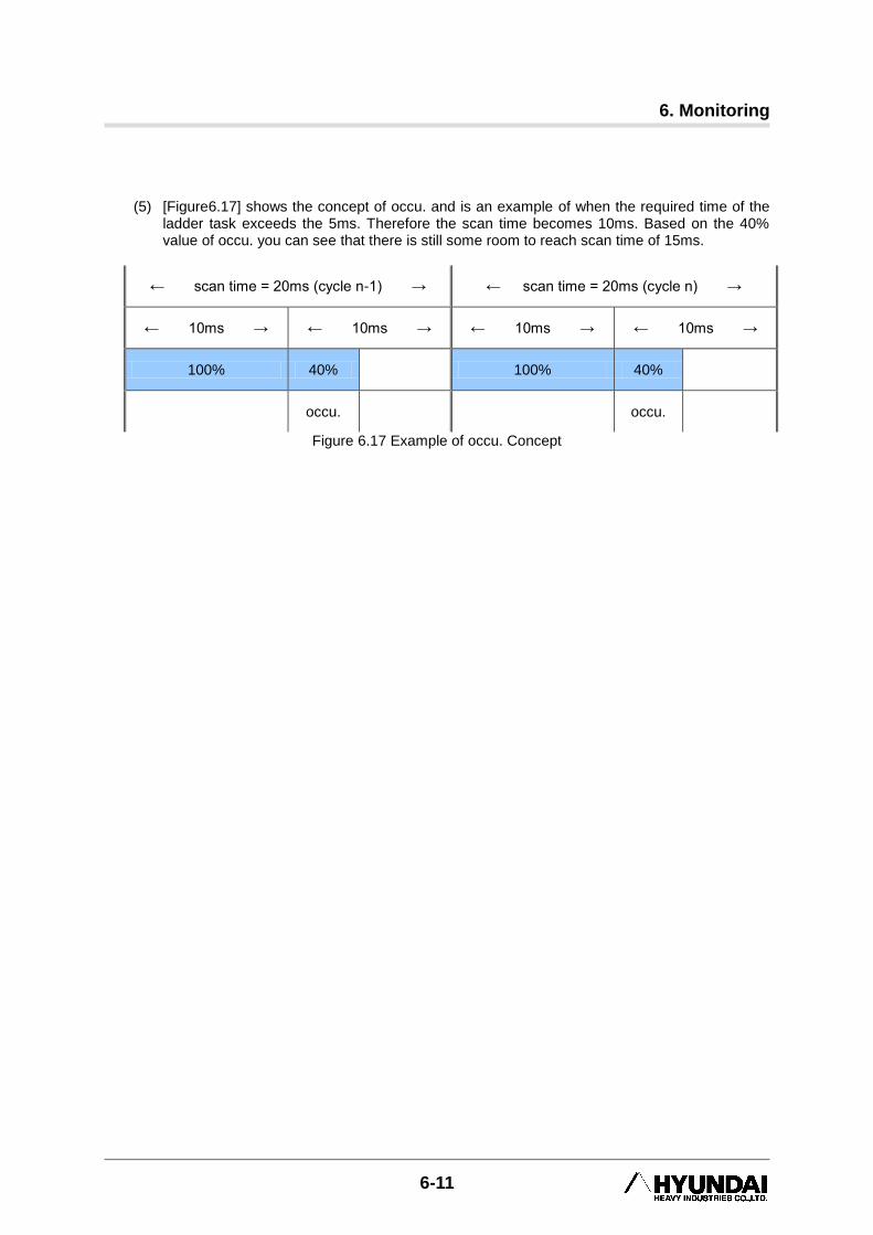
6. Monitoring
6-11
(5) [Figure6.17] shows the concept of occu. and is an example of when the required time of the
ladder task exceeds the 5ms. Therefore the scan time becomes 10ms. Based on the 40% value of occu. you can see that there is still some room to reach scan time of 15ms.
← scan time = 20ms (cycle n-1) → ← scan time = 20ms (cycle n) →
← 10ms → ← 10ms → ← 10ms → ← 10ms →
100% 40% 100% 40%
occu. occu.
Figure 6.17 Example of occu. Concept

● Head Office ● A/S Center
Tel. 82-52-202-7901 / Fax. 82-52-202-7900 Tel. 82-52-202-5041 / Fax. 82-52-202-7960
1, Jeonha-dong, Dong-gu, Ulsan, Korea
● Seoul Office
Tel.82-2-746-4711 / Fax. 82-2-746-4720
140-2, Gye-dong, Jongno-gu, Seoul, Korea
● Ansan Office
Tel.82-31-409-4945 / Fax.82-31-409-4946
1431-2, Sa-dong, Sangnok-gu, Ansan-si, Gyeonggi-do, Korea
● Cheonan Office
Tel.82-41-576-4294 / Fax.82-41-576-4296
355-15, Daga-dong, Cheonan-si, Chungcheongnam-do, Korea
● Daegu Office
Tel.82-53-746-6232 / Fax.82-53-746-6231
223-5, Beomeo 2-dong, Suseong-gu, Daegu, Korea
● Gwangju Office
Tel. 82-62-363-5272 / Fax. 82-62-363-5273
415-2, Nongseong-dong, Seo-gu, Gwangju, Korea
● 본사 ● A/S 센터
Tel. 052-202-7901 / Fax. 052-202-7900 Tel. 82-52-202-5041 / Fax. 82-52-202-7960
울산광역시 동구 전하동 1 번지
● 서울 사무소
Tel. 02-746-4711 / Fax. 02-746-4720
서울특별시 종로구 계동 140-2 번지
● 안산 사무소
Tel. 031-409-4945 / Fax. 031-409-4946
경기도 안산시 상록구 사동 1431-2 번지
● 천안 사무소
Tel. 041-576-4294 / Fax. 041-576-4296
충남 천안시 다가동 355-15 번지
● 대구 사무소
Tel. 053-746-6232 / Fax. 053-746-6231
대구광역시 수성구 범어 2 동 223-5 번지
● 광주 사무소
Tel. 062-363-5272 / Fax. 062-363-5273
광주광역시 서구 농성동 415-2 번지