manual horno tubular
DESCRIPTION
manual ilustrativo referente al hornoTRANSCRIPT

Type F21100Tube Furnace
OPERATION MANUALAND PARTS LIST
SERIES 1029
Model # Voltage ControlF21124 100 ManualF21125 120 ManualF21120 240 ManualF21130 240 Single Set PointF21130-33 230 Single Set PointF21135 120 Single Set Point
BARNSTEAD|THERMOLYNE CORPORATION
LT1029X1T • 3/7/97

2
Table of ContentsSafety Information ................................................................................................................................3
Alert Boxes ............................................................................................................................................3 Warnings ................................................................................................................................................4 Introduction ............................................................................................................................................5
Intended Use......................................................................................................................................5 General Usage ..................................................................................................................................5 Principles of Operation ......................................................................................................................5
General Specifications for Furnaces ......................................................................................................8 Environmental Conditions ..................................................................................................................8
Declaration of Conformity ......................................................................................................................9 Unpacking ............................................................................................................................................10 Installation ............................................................................................................................................11 Operation of Manual and Automatic Models ........................................................................................12 Manual Control Models (F21124, F21125, F21120) ............................................................................12
Pyrometer ........................................................................................................................................12 Single Set Point Temperature Control (Automatic) (F21130, F21130-33, F21135)..............................13
Adjustment of Parameters (See Figure 1) ......................................................................................13 Furnace Loading ..................................................................................................................................16 Preventive Maintenance ......................................................................................................................17
General Cleaning Instructions..........................................................................................................17 Troubleshooting....................................................................................................................................18 Maintenance and Servicing..................................................................................................................21
To Replace Vestibule End Caps ......................................................................................................21 To Replace The Heating Element Tube (Without Case Assembly) ................................................21 To Replace Control Base ................................................................................................................22 To Replace Pyrometer (Manual Control Models) ............................................................................22 To Replace Manual Temperature Control Switch ............................................................................23 To Replace Furnace Chamber ........................................................................................................24 To Replace Type K (Chromel/Alumel) Thermocouple (Manual Control Models) ............................24To Replace Type Platinel II Thermocouple (Single Set Point Control Models) ..............................25
Replacement Parts List ........................................................................................................................26 Ordering Procedures ............................................................................................................................27Wiring Diagrams ..................................................................................................................................28 Warranty ..............................................................................................................................................30
Table Of Contents

3
Safety InformationYour Thermolyne Tube Furnace has been designed withfunction, reliability, and safety in mind. It is your respon-sibility to install it in conformance with local electricalcodes. For safe operation, please pay attention to thealert boxes throughout the manual.
WARNINGTo avoid electrical shock, this furnace must:1. Use a properly grounded electrical outlet of correct
voltage and current handling capacity.2. Disconnect from the power supply prior to mainte-
nance and servicing.3. Always use a properly sized combustion tube.To avoid personal injury:1. Do not use in the presence of flammable or combusti-
ble materials ; fire or explosion may result. Thisdevice contains components which may ignite suchmaterial.
2. Refer servicing to qualified personnel.
HOT SURFACE
“Caution: Hot Surface. Avoid Contact.” To avoid burns,do not touch this furnace on the exterior or interior sur-faces during use or for a period of time after use.
Alert Boxes
WARNING
Warnings alert you to a possibility of personal inju-ry.
HOT SURFACE
Hot surfaces alert you to a possibility of personalinjury if you come in contact with a surface duringuse or for a period of time after use.
CAUTION
Cautions alert you to a possibility of damage tothe equipment.
NOTE
Notes alert you to pertinent facts and conditions.
General Information

4
Please note the following warnings:
WARNINGThis warning is presented for compliance with California Proposition 65 and other regulatory agencies and
only applies to the insulation in this product. This product contains refractory ceramic, refractory ceramic fiberor fiberglass insulation, which can produce respirable dust or fibers during disassembly. Dust or fibers can
cause irritation and can aggravate pre-existing respiratory diseases. Refractory ceramic and refractory ceram-ic fibers (after reaching 1000°C) contain crystalline silica, which can cause lung damage (silicosis). The Inter-national Agency for Research on Cancer (IARC) has classified refractory ceramic fiber and fiberglass as pos-
sibly carcinogenic (Group 2B), and crystalline silica as carcinogenic to humans (Group 1).
The insulating materials can be located in the door, the hearth collar, in the chamber of the product or underthe hot plate top. Tests performed by the manufacturer indicate that there is no risk of exposure to dust or res-pirable fibers resulting from operation of this product under normal conditions. However, there may be a risk ofexposure to respirable dust or fibers when repairing or maintaining the insulating materials, or when otherwisedisturbing them in a manner which causes release of dust or fibers. By using proper handling procedures andprotective equipment you can work safely with these insulating materials and minimize any exposure. Refer to
the appropriate Material Safety Data Sheets (MSDS) for information regarding proper handling and recom-mended protective equipment. For additional MSDS copies, or additional information concerning the handling
of refractory ceramic products, please contact the Customer Service Department at Barnstead|ThermolyneCorporation at 1-800-553-0039.
1-800-446-60601-800-553-0039
Warning

5
IntroductionIntended UseThe type 21100 furnaces are small, inexpensive fur-naces ideally suited for school, chemical and industriallaboratories. They are intended for applications requiringtemperatures up to 1100°C for manual control bases ortemperatures up to 1200°C for the electronic single setpoint control bases. See specification sheet for continu-ous and intermittent operating temperatures.
General UsageDo not use this product for anything other than its in-tended usage.
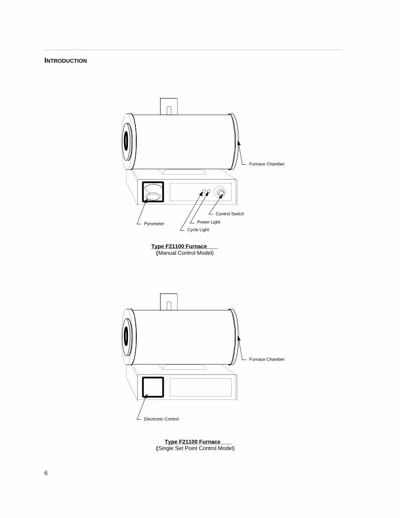
Principles of OperationThe furnace chamber is heated by heating elements em-bedded in a refractory material. The tubular chamber isinsulated with a ceramic fiber insulation. The furnacechamber is supported by the control base which alsohouses the electrical connections. Two types of controlsare used:1. Manual Control - A percentage input control whichcompensates for line voltage fluctuation and ambienttemperature changes. The temperature is measured bya thermocouple and is displayed on a pyrometer.2. Single Set Point Control - An electronic controlwhich enables the user to bring the furnace up to a pre-set temperature and hold the temperature. (See Figure1)
Introduction
Figure 1 Single Set Point Control
6
Furnace Chamber
Pyrometer Cycle Light
Power Light
Control Switch
Type F21100 Furnace (Manual Control Model)
Furnace Chamber
Electronic Control
Type F21100 Furnace (Single Set Point Control Model)
INTRODUCTION

7
THERMOCOUPLE ELEMENTLEAD WIRE
WHITE
YELLOW +
REDTHERMOCOUPLELEAD WIRE
POWER CORD
BLACK
GROUND WIRE(GREEN)
ELEMENT LEAD WIRE
Figure 2a (All Models except F21 130-33)
Figure 2b (Model F21 130-33)
INTRODUCTION

8
Environmental Conditions Operating: 17°C - 27°C; 20% to 80% relative humidity,
non-condensing. Installation Category II (over-voltage) in accordance with IEC 664. Pollution De-gree 2 in accordance with IEC 664. Altitude limit: 2,000 meters.
Storage: -25°C to 65°C; 10% to 85% relative humidity.
General Specifications
Model Number F21135, *F21125 F21130, *F21120 *F21124 F21130-33Dimensions - In.(cm)Overall Width 16 (40.6) 16 (40.6) 16 (40.6) 16 (40.6)
Height 14.63, *14.75 14.63, *14.75 14.63, *14.75 14.63, *14.75(37.2, *37.5) (37.2, *37.5) (37.2, *37.5) (37.2, *37.5)
Chamber Width 12 (30.5) 12 (30.5) 12 (30.5) 12 (30.5)Height 1.0 & 2.0 Dia. 1.0 & 2.0 Dia. 1.0 & 2.0 Dia. 1.0 & 2.0 Dia.
(2.5 & 5) (2.5 & 5) (2.5 & 5) (2.5 & 5)
Weight - lbs (Kg) 19 lbs 5 oz (8.8) 19 lbs 5 oz (8.8) 19 lbs 5 oz (8.8) 19 lbs 5 oz (8.8)*19 lbs 12 oz (9.0) *19 lbs 12 oz (9.0) *19 lbs 12 oz (9.0) *19 lbs 12 oz (9.0)
Electrical RatingsVolts 120 240 100 230Amps 11.25 5.6 13.5 5.4Watts 1350 1350 1350 1240Freq. 50/60 50/60 50/60 50/60Phase 1 1 1 1
Temperature 100 - 1200°C 100 - 1200°C 100 - 1200°C 100 - 1200°CRatings °C *371 - 1100°C *371 - 1100°C *371 - 1100°C *371 - 1100°C
* For models with manual control.Temperatures specified, obtained with both 1.0” Dia. and 2.0” Dia. ceramic process tubes, 17” long.

9
Declaration of Conformity (-33models only)Barnstead|Thermolyne hereby declares under its sole re-sponsibility that this product conforms with the technicalrequirements of the following standards:
EMC: EN 50081-1 Generic Emission Standard; EN50082-1 Generic Immunity Standard;
Safety: IEC 1010-1-92 Safety requirements for electrical equipment for measurement, control, and laboratory use; Part I: General Requirements
IEC 1010-2-010 Part II: Particular requirements forlaboratory equipment for the heating of materialsper the provisions of the Electromagnetic CompatabilityDirective 89/336/EEC, as amended by 92/31/EEC and93/68/EEC, and per the provisions of the Low Voltage Di-rective 73/23/EEC, as amended by 93/68/EEC.
The authorized representative located within the EuropeanCommunity is:
European ManagerBarnstead|ThermolyneSaarbrückener Str. 248D-38116 BraunschweigGermany
Copies of the Declaration of Conformity are available uponrequest.
Declaration of Conformity

10
UnpackingUnpack furnace from box and remove packing materialfrom inside furnace chamber. The furnace is suppliedwith a three wire cord and plug & 2-JC211x1 (1") diame-ter tube mounting vestibules. Furnace does not containa refractory process tube.
NOTE
Contact the dealer from which your furnace waspurchased to obtain proper process tube andinformation regarding its use.
Unpacking

11
InstallationSITE SELECTION: Install furnace on a sturdy surface and
allow space for ventilation.
The electrical specifications are located on the specificationplate on the back of the furnace. Consult Barnstead/Ther-molyne if your electrical service is different than those list-ed on the specification plate. Prior to connecting your Type21100 furnace to your electrical supply, be sure the poweror control switch is in the OFF position.
Installation
CAUTION
Be sure ambient temperature does not exceed104°F (40°C); ambients above this level mayresult in damage to the control.
Allow at least six inches of space between thefurnace and any combustible surface. This per-mits the heat from the furnace case to escapeso as not to create a possible fire hazard.
NOTE
Furnace comes with both 1" and 2" dia. endcaps. Install the end cap which fits the tube youplan to use.
WARNING
To avoid electrical shock, this furnace must beinstalled by a competent, qualified electricianwho insures compatibility among furnace speci-fication, power source and ground coderequirements.
12
Operation of Manual and Automatic Models
Observe These W arnings Before OperatingYour Furnace:
Manual Control Models(F21124, F21125, F21120)
The control switch is a combination ON/OFF switch andtemperature control. The furnace is ON at any setting ofthe control switch except in the OFF position. The greenpower light will be illuminated as long as power isapplied. Turn the control switch counterclockwise to setrate of heating.
Cycle Light: The amber cycle light will illuminate when-ever the power is being applied to the elements.
Power Light: The green power light will illuminate when-ever the control switch is turned to a setting other thanthe OFF position.
The marks on the control indicate the percent of timepower is applied to the heating elements. An increase inpercent time “On” results in a higher chamber tempera-ture. Adjust control switch to maintain desired tempera-ture setting. To turn the furnace off, turn control eitherfully clockwise or fully counterclockwise to the OFF posi-tion.
PyrometerThe pyrometer with a thermocouple indicates the cham-ber temperature. It does not control the furnace in anymanner. It is provided to enable the operator to observethe temperature within the chamber.
Operation
WARNING
Do not use in the presence of flammable orcombustible chemicals. Fire or explosion mayresult; this device contains components whichmay ignite such materials.
HOT SURFACE
“Caution: Hot Surface. Avoid Contact.” To avoidburns, do not touch this furnace on the exterioror interior surfaces during use or for a period oftime after use.
CAUTION
Monitor furnace if percent time input is setgreater than 40% on and particularly when thecontrol is set on “HI” or in the red zone. The fur-nace may overheat and burn out the elementsor thermocouple if not properly monitored underthese conditions.
13
Single Set Point T emperatureControl (Automatic) (F21 130,F21130-33, F21135)This furnace control consists of a microprocessor basedthree-mode (Proportional, Integral, Derivative), single setpoint temperature control. The control features programma-ble overtemperature protection and thermocouple breakprotection.
Power Switch: Switch power switch to the “ON” position.The switch will illuminate when power is on.
Cycle Indicator: The amber “OP” cycle light will illuminatewhenever the power is being applied to the heating ele-ments. (See Figure 1).
Digital Readout The digital readout continuously displays chamber (upperdisplay) and set point (lower display) temperatures unlessthe PAR (parameter) button is depressed.
Initial Startup:When the power switch is turned on, the control will per-form a self-test to make sure control is operating properly.(If all four 1’s do not light up or fail to go to “8888,” contactThermolyne.)
Adjustment of Parameters (See Figure 1)To Illuminate “up,” “down,” and “scroll” buttons, touch any-where on front panel. See Figure 1 “Secret Key.”
Set Point T emperaturePush “up” or “down” button to modify temperature set point(lower digital display).
Temperature IndicationPush scroll button once. “°C” will appear. This indicatestemperature measurement. (Contact Thermolyne if controlneeds to be changed to °F.)
Ramp to Set point Operation — SP .rrThe set point ramp rate is designed to allow a user to re-duce the heat-up rate or cooling rate that the furnace nor-mally exhibits. When not using this feature, the furnace willoperate at its maximum heat-up rate and cool down capa-bility.
NOTE
The temperature control in this automatic modelsis a single set-point device. By using the “up” or“down” push buttons, a specific temperature canbe chosen. The control will cause the furnacechamber to heat to the chosen temperature andhold it at this temperature until you turn off thepower switch or select another temperature.
NOTE
When performing the following steps rememberthat if more than eight to ten seconds elapsebefore the buttons are used again, the displayscreen will automatically switch back to display-ing chamber temperature. If this happens, lightup the front panel again and step through eachparameter until you reach the point at which theinterruption occurred. The parameter values youchecked earlier, however, will not be lost oraltered. Holding down on the scroll buttonallows longer viewing time.
OPERATION

14
To access SP.rr set point ramp rate:1. Push scroll button until AL.SP appears.2. Push Secret Key to enter protected list.3. Push scroll button until SP.rr (Set point Ramp
Rate) appears. SP.rr is expressed in °C/min.
If you desire to ramp to the set temperatures at a speci-fied rate, depress “UP” or “DOWN” button to give currentsetting of ramp rate, then depress “UP” or “DOWN” but-ton again until you achieve desired setting.
The set point ramping feature is started by setting SP.rrto any value except OFF. Ramping is initiated only byone of two conditions:•Power-up (Upon power-up, ramping always starts fromthe current furnace temperature.)•Change in set point.
If you choose not to use the ramp to set point feature,set SP.rr to OFF.
CAUTION
Do not change any parameters in the “protectedlist” other than SP.rr. Changing other parame-ters could result in furnace malfunction.
NOTE
Remember when setting SP.rr you must staywithin the heating and cooling capabilities of thefurnace. See specification sheet.
NOTE
SP.rr must be set to Off if Self Tuning isselected.
Setpoint
Original
Furnace Temp.
Without Ramping
With High SP.rr With Low SP.rr
Without Ramping
With High SP.rr
With Low SP.rr
Change in SetpointPower Up
OPERATION

15
TuningThis control incorporates a self tuning feature which deter-mines the optimum control parameters for the best temper-ature accuracy. We recommend that you tune the furnaceto your specific application to obtain the best results. Per-form the following procedures when you first set up yourfurnace and each time you change your load type or oper-ating temperature.
Push scroll button until “tunE” appears. To start tuning func-tion, push “UP” button. To stop tuning function, push“DOWN” button.
When the tuning process is started, the lower display willflash “tunE” along with the furnace temperature set point.During tuning the temperature set point cannot bechanged. To change temperature set point, “tunE” must beturned off.
Overtemperature ProtectionThe control is fitted with a solid-state relay which is de-en-ergized in the alarm mode. If the primary control circuitfails, the OTP will control the furnace temperature at thepreset value you have entered. It does not shut off the fur-nace but will maintain the chamber temperature at thatvalue.
To set the OTP value, depress the scroll button until“AL.SP” (Alarm Set Point) appears. The lower displayshould indicate 1210°C. Depress either the “UP” or“DOWN” push button to select the OTP value you desire.Thermolyne recommends that you set the value either atthe maximum operating temperature of the furnace or avalue of 20 degrees above your working temperature if youdesire to provide protection for your workload.
NOTE
If the power to furnace is turned off orinterrupted while in “tuning,” upon return-ing power to furnace, the controlled dis-play will indicate “LINE FAIL” becausesample data could be questionable. To re-start tuning, refer to “Tuning” procedure.
If the control cannot maintain temperatureset point, “tunE FAIL” will appear on display.First correct problem for not maintainingtemperature set point, then restart tuning.
OPERATION

16
Furnace LoadingFor best results of furnace loading and temperature uni-formity, use only the center six inches of the furnacechamber.
Keep objects away from thermocouple.
Use insulated tongs and mittens when loading and un-loading furnace.
Always wear safety glasses.
Use the proper process tube.
CAUTION
Do not overload your furnace chamber. Failureto observe this caution could result in damageto furnace components.
Furnace Loading

17
Preventive MaintenanceContamination is a major cause of element failure, there-fore, when possible, remove the fume forming material be-fore heating. (e.g., cleaning cutting oil from tool steel).
Housekeeping is vital to your electric furnace—KEEP ITCLEAN! Run your furnace up to 871°C empty occasionallyto burn off the contamination that may exist on the insula-tion and elements. Run for approximately two hours withthe process tube removed.
Element life is reduced somewhat by repeated heating andcooling. If the furnace is to be used again within a fewhours, it is best to keep it at the operating temperature orat a reduced level such as 260°C.
During normal use the thermocouple in your furnace canbecome oxidized and cause inaccurate readings; therefore,we suggest that if you regularly use your furnace youshould change your thermocouple once every sixmonths to assure the accuracy of your meter readings .
General Cleaning InstructionsWipe exterior surfaces with lightly dampened cloth contain-ing mild soap solution.
WARNING
To avoid electrical shock, this furnace must al-ways be disconnect from the power supply pri-or to maintenance and servicing.
Refer servicing to qualified personnel.
Preventative Maintenance

18
Troubleshooting
WARNING
THIS FURNACE CONTAINS REFRACTORY CERAMIC INSULATION WHICH CAN PRODUCE RESPI-RABLE FIBERS AND DUST WHEN HANDLED. THESE FIBERS CAN CAUSE IRRITATION AND CANAGGRAVATE PRE-EXISTING RESPIRATORY DISEASE. THE INTERNATIONAL AGENCY FORRESEARCH ON CANCER (IARC) HAS CLASSIFIED REFRACTORY CERAMIC FIBER AS POSSIBLYCARCINOGENIC.
AFTER SERVICE REFRACTORY CERAMIC FIBER DUST MAY CONTAIN CRYSTALLINE SILICA,WHICH MAY CAUSE LUNG DAMAGE (SILICOSIS) AND WHICH HAS BEEN CLASSED BY IARC AS APROBABLE CARCINOGEN.
The refractory ceramic materials are located in the hearth collar and in the chamber of the furnace. Testsperformed by the manufacturer indicate that there is no significant risk of exposure to dust or respirablerefractory ceramic fiber resulting from operation of the equipment under normal conditions. However,there may be a risk of exposure to respirable refractory ceramic dust or fiber when repairing or maintain-ing the insulating materials, or when otherwise disturbing the materials in a manner which causes re-lease of dust or fibers therefrom. Through the use of proper handling procedures you can work safelywith these insulating materials and minimize any exposure. Accordingly, before you repair or replace anyinsulating materials, or perform any other servicing on this product which could disturb or cause expo-sure to dust from insulating materials, you should consult the appropriate Material Safety Data Sheets(MSDS’s) for such products with respect to proper handling and appropriate protective equipment. Foradditional MSDS’s, or additional information concerning the handling of refractory ceramic products,please contact the Customer Service Department of Barnstead/Thermolyne Corporation.
REFER SERVICING TO QUALIFIED PERSONNEL.
WARNING
Disconnect from the power supply prior to maintenance and servicing.
Refer servicing to qualified personnel.
Troubleshooting
19
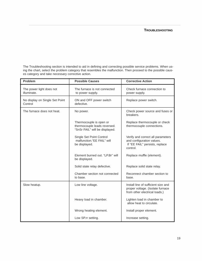
The Troubleshooting section is intended to aid in defining and correcting possible service problems. When us-ing the chart, select the problem category that resembles the malfunction. Then proceed to the possible caus-es category and take necessary corrective action.
Problem Possible Causes Corrective Action
The power light does not The furnace is not connected Check furnace connection to illuminate. to power supply. power supply.
No display on Single Set Point ON and OFF power switch Replace power switch.Control defective.
The furnace does not heat. No power. Check power source and fuses or breakers.
Thermocouple is open or Replace thermocouple or check thermocouple leads reversed. thermocouple connections.“SnSr FAIL” will be displayed.
Single Set Point Control Verify and correct all parametersmalfunction.“EE FAIL” will and configuration values.
be displayed. If “EE FAIL” persists, replace control.
Element burned out. “LP.Br” will Replace muffle (element).be displayed.
Solid state relay defective. Replace solid state relay.
Chamber section not connected Reconnect chamber section to to base. base.
Slow heatup. Low line voltage. Install line of sufficient size andproper voltage. (Isolate furnacefrom other electrical loads.)
Heavy load in chamber. Lighten load in chamber toallow heat to circulate.
Wrong heating element. Install proper element.
Low SP.rr setting. Increase setting.
TROUBLESHOOTING
20
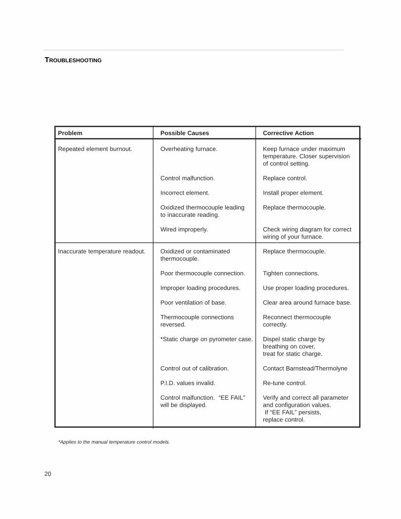
Problem Possible Causes Corrective Action
Repeated element burnout. Overheating furnace. Keep furnace under maximumtemperature. Closer supervisionof control setting.
Control malfunction. Replace control.
Incorrect element. Install proper element.
Oxidized thermocouple leading Replace thermocouple.to inaccurate reading.
Wired improperly. Check wiring diagram for correct wiring of your furnace.
Inaccurate temperature readout. Oxidized or contaminated Replace thermocouple.thermocouple.
Poor thermocouple connection. Tighten connections.
Improper loading procedures. Use proper loading procedures.
Poor ventilation of base. Clear area around furnace base.
Thermocouple connections Reconnect thermocouple reversed. correctly.
*Static charge on pyrometer case. Dispel static charge by breathing on cover,treat for static charge.
Control out of calibration. Contact Barnstead/Thermolyne
P.I.D. values invalid. Re-tune control.
Control malfunction. “EE FAIL” Verify and correct all parameter will be displayed. and configuration values.
If “EE FAIL” persists,replace control.
*Applies to the manual temperature control models.
TROUBLESHOOTING

21
Maintenance and ServicingTo Replace V estibule End Capsa. Disconnect furnace from power supply.b Remove the metal end cap.c. Remove old vestibule. Insert the new vestibule, aligning
the two holes in the vestibule with the holes on the brack-et.
d. Before pushing the metal end caps back onto the cham-ber, insert the two screws through the holes in the metalend cap and vestibule. Then, start the two screws into theholes in the bracket two or three turns, push the metalend cap onto the chamber and finish tightening the twoscrews.
e. Reconnect furnace to power supply.
To Replace The Heating Element T ube (WithoutCase Assembly):a. Disconnect furnace from power supply.b. Disconnect the cord from furnace chamber to control
base. Identify the color and placement of the thermocou-ple extension wires and disconnect from control base.
c. Remove furnace chamber from the bracket.d. Remove both end caps and vestibules of furnace cham-
ber.e. Remove terminal plate with six screws to expose wiring.
(Note placement and connection of thermocouple andelement wires.)
f. Remove two element lead wires from terminal block. Also,remove thermocouple by removing two screws on blockthen pulling it straight back.
g. Remove the four screws that secure heating element tubeinside the case, then slide out the old heating elementtube.
h. Insert new heating element tube and thread each elementlead wire through the plastic bushings.
i. Secure heating element tube to case.j. Reinstall thermocouple and connect thermocouple and
new element lead wires to terminal block.k. Replace terminal plate.l. Insert the screw on the terminal plate through the mount-
ing bracket and secure with knob.m. Replace both end caps and vestibules.n. Reconnect power cord from furnace chamber to control
base.
Maintenancing and Servicing

22
o. Reconnect thermocouple extension wires to controlbase terminal block. Looking from the rear of the fur-nace, reconnect the red wire to the terminal on the rightside of the block. The yellow wire connects to the termi-nal on the left side of the terminal block.
p. Reconnect furnace to power supply.
To Replace Control Base:a. Disconnect furnace from power supply.b. Disconnect power cord from control base to furnace
chamber. Identify the color and placement of the ther-mocouple extension wires and disconnect wires fromcontrol base.
c. Remove bracket and furnace chamber from controlbase.
d. Slide the bracket onto the new control base and secure.e. Plug power cord from furnace chamber into new control
base.f. Reconnect thermocouple extension wires as identified
in Step b.g. Reconnect furnace to power supply.
To Replace Pyrometer (Manual Control Mod -els)a. Disconnect furnace from power supply.b. Disconnect power cord from furnace chamber to control
base and disconnect thermocouple extension wiresfrom control base.
c. Turn control base upside down and remove bottom cov-er.
d. Remove yellow and red wires from pyrometer.e. Remove pyrometer from dial plate of control base.f. Insert new pyrometer and secure to dial plate.g. Slide the yellow wire over the positive terminal as desig-
nated by the positive sign (+) on the back of the pyrom-eter and secure. Slide the red wire over the negativeterminal on the pyrometer and secure. (Make sure con-nections are tight or erroneous readout will result.)
h. Replace bottom cover.i. Turn control base upright and secure furnace chamber
to it.j. Reconnect power cord from furnace chamber to control
base.
MAINTENANCING AND SERVICING

23
k. Looking from the rear of the furnace, reconnect red cod-ed thermocouple extension wire to the terminal on theright side of the terminal block. Reconnect yellow thermo-couple extension wire to the terminal on the left side ofthe terminal block.
l. Reconnect furnace to power supply.
To Replace Manual T emperature ControlSwitch:a Disconnect furnace from power supply.b. Disconnect power cord from furnace chamber to control
base and disconnect thermocouple extension wires fromcontrol base.
c. Turn control base upside down and remove bottom cover.d. Remove control knob with two Allen set screws.e. Remove two screws holding control to dial plate.f. Disconnect wires from control. Identify or mark wires dis-
connected from control to insure proper placement andconnection when reinstalling. Remove defective control.
g. Looking from the rear of the furnace, insert new controlwith the H1 (vertical lead) and H2 (horizontal lead) leadson top and secure to dial plate.
h. Turn shaft of control until the flat section is facing up(opposite of the percent time on indicating mark). Slideknob over shaft and align the OFF mark with the percenttime on indicating mark. Secure knob with two Allen setscrews.
i. Reconnect the wires identified or marked in Step (f) tonew control.
j. Replace bottom cover.k. Turn control base upright and secure furnace chamber to
it.l. Reconnect power cord from furnace chamber to control
base.m. Looking from the rear of the furnace, reconnect the red
coded thermocouple extension wire to the terminal on theright side of the terminal block. Reconnect yellow thermo-couple extension wire to the terminal on the left side ofterminal block.
n. Reconnect furnace to power supply.
NOTE
Perform only maintenance described in thismanual. Contact an authorized dealer or ourfactory for parts and assistance.
MAINTENANCE AND SERVICING

24
To Replace Furnace Chamber:a. Disconnect furnace from power supply.b. Disconnect power cord from furnace chamber to
control base. Identify the color and placement ofthermocouple extension wires and disconnect fromcontrol base.
c. Remove black knob holding furnace chamber tobracket and remove furnace chamber.
d. Remove terminal plate on back of furnace chamber.(Note placement and connection of wires.)
e. Disconnect thermocouple extension wires and powercord from terminal block.
f Remove back terminal plate on new furnace cham-ber.
g. Insert power cord and thermocouple extension wiresthrough their proper holes in the bracket on the newfurnace chamber. (See Figure 2a or 2b for place-ment and connection of wires.)
h. Replace back terminal plate.i. Insert screw on back terminal plate through bracket
slot and secure with knob.j Reconnect power cord from furnace chamber to con-
trol base.k. Reconnect thermocouple extension wires as identi-
fied in Step b.l. Reconnect furnace to power supply.
To Replace T ype K (Chromel/Alumel) Ther -mocouple (Manual Control Models):a. Disconnect furnace from power supply.b. Disconnect the cord from furnace chamber to control
base and also disconnect thermocouple extensionwire from control base.
c. Remove knob that holds furnace chamber to thebracket and remove the furnace chamber.
d. Remove terminal plate on back of furnace chamber.e. Remove two screws that secure the old thermocou-
ple and remove thermocouple by pulling straightback.
f. Insert the new thermocouple until tip extends ap-proximately 1/4" into the heating chamber. Connectthe lead marked (+) on insulator of thermocouple tothe terminal across from yellow thermocouple exten-sion wire, and fasten the other thermocouple lead (-)to the remaining terminal. (See Figure 2a or 2b.)
MAINTENANCE AND SERVICING

25
(A polarity test of the lead wire is easily made with theuse of a magnet. On chromel/alumel thermocouples andextension wires, the non-magnetic wire is positive (+ )and the magnetic wire is negative (- ).
g. Replace terminal plate.h. Insert the screw on the terminal plate through the mount-
ing bracket and secure with knob.i. Reconnect power cord from furnace chamber to control
base.j. Looking from the rear of the furnace, reconnect the red
coded thermocouple extension wire to the terminal on theright side of the block. The yellow thermocouple exten-sion wire connects to the terminal on the left side of theterminal block.
k. Reconnect furnace to power supply.
To Replace T ype Platinel II Thermocouple (Sin -gle Set Point Control Models)a. Disconnect furnace from power supply.b. Disconnect the cord from furnace chamber to control
base and also disconnect thermocouple extension wiresfrom control base.
c. Remove knob that holds furnace chamber to the bracketand remove the furnace chamber.
d. Remove terminal plate on back of furnace chamber.e. Remove two screws that secure the old thermocouple
and remove thermocouple by pulling straight back.f. Insert the new thermocouple until tip extends approxi-
mately 1/4" into heating chamber.g. Connect the blue and yellow beaded thermocouple lead
to the terminal across from yellow thermocouple exten-sion wire and the other thermocouple lead to the remain-ing terminal.
h. Insert the screw on the terminal plate through the mount-ing bracket and secure with knob.
i. Reconnect power cord from furnace chamber to controlbase.
j. Looking from the rear of the furnace, reconnect the redcoded thermocouple extension wire to the terminal on theright side of the block. The yellow thermocouple exten-sion wire connects to the terminal on the left side of theterminal block.
k. Reconnect furnace to power supply.
MAINTENANCING AND SERVICING
26
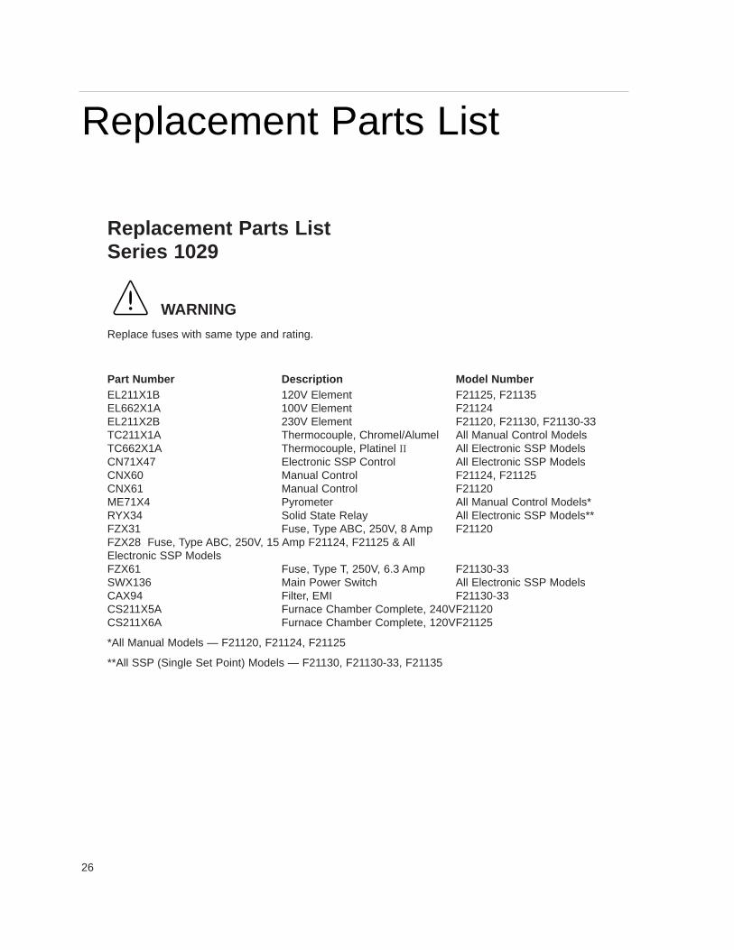
Replacement Parts ListSeries 1029
WARNING
Replace fuses with same type and rating.
Part Number Description Model NumberEL211X1B 120V Element F21125, F21135EL662X1A 100V Element F21124EL211X2B 230V Element F21120, F21130, F21130-33TC211X1A Thermocouple, Chromel/Alumel All Manual Control ModelsTC662X1A Thermocouple, Platinel II All Electronic SSP ModelsCN71X47 Electronic SSP Control All Electronic SSP ModelsCNX60 Manual Control F21124, F21125CNX61 Manual Control F21120ME71X4 Pyrometer All Manual Control Models*RYX34 Solid State Relay All Electronic SSP Models**FZX31 Fuse, Type ABC, 250V, 8 Amp F21120FZX28 Fuse, Type ABC, 250V, 15 Amp F21124, F21125 & AllElectronic SSP ModelsFZX61 Fuse, Type T, 250V, 6.3 Amp F21130-33SWX136 Main Power Switch All Electronic SSP ModelsCAX94 Filter, EMI F21130-33CS211X5A Furnace Chamber Complete, 240VF21120CS211X6A Furnace Chamber Complete, 120VF21125
*All Manual Models — F21120, F21124, F21125
**All SSP (Single Set Point) Models — F21130, F21130-33, F21135
Replacement Parts List

27
Ordering ProceduresPlease refer to the Specification Plate for the complete modelnumber, serial number, and series number when requestingservice, replacement parts or in any correspondence concern-ing this unit.
All parts listed herein may be ordered from theBarnstead|Thermolyne dealer from whom you purchasedthis unit or can be obtained promptly from the factory. Whenservice or replacement parts are needed we ask that youcheck first with your dealer. If the dealer cannot handle yourrequest, then contact our Customer Service Department at319-556-2241 or 800-553-0039.
Prior to returning any materials to Barnstead|ThermolyneCorp., please contact our Customer Service Department for a“Return Goods Authorization” number (RGA). Materialreturned without a RGA number will be refused.
Ordering Procedures

28
Wiring Diagram for Models F21 120, F21124, F21125
Wiring Diagrams
DIAGRAM COMPONENT LIST
FUSEF1
COLD POWER CORD & PLUG
C/A THERMOCOUPLE
POWER CONNECTOR "COLD" RECPT.
POWER ENTRY MODULE
HEATING ELEMENT
TERMINAL BLOCK
TERMINAL BLOCK
CORD SET
PYROMETER
FUSEF2
P2
TC
TB2
TB1
P1
M1
J2
J1
H1
CYCLE LIGHT, AMBER
PILOT LIGHT, GREENINPUT CONTROL
CAPACITOR
DS2
DS1CN1
C1
DESCRIPTIONNO.REF.
C1
B
B
F1 & F2
100, 120, 240 VAC
W
B
H1
CN1
P
H2
L2L1
GND
G/Y G/Y
LNJ1
P1
P2
L
N
GND
J2
L
N
GND
TB2
TC
+ H1
DS2
DS1
W
W
WH2
RY
TB1
M1
WH1
°C/°F
+ -
RY
29
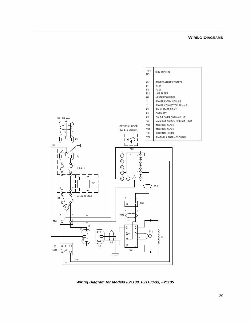
Wiring Diagram for Models F21 130, F21130-33, F21135
WIRING DIAGRAMS
F21130-33 ONLY
F1 & F2
NL
V
SSRK1
+
GRY
J1
G
TB1
B
GN
D
B
W
W
W
L
S1
B
N
W
89 - 250 VAC
GND
GB
G/Y
P1
W
P2
TB2
J2
WH1
R
FL1
R
L
125
4
3
2
TB3
TC1
Y
+ H1
WH2
Y
+
N
7
8
9
1011
SAFETY SWITCHOPTIONAL, DOOR/
CN1
V1 + 6
TEMPERATURE CONTROLCN1
TERMINAL BLOCK
COLD POWER CORD & PLUG
PLATINEL II THERMOCOUPLE
TERMINAL BLOCK
TERMINAL BLOCK
MAIN PWR SWITCH, W/PILOT LIGHT
SOLID STATE RELAY
HEATER/CHAMBER
POWER CONNECTOR, FEMALE
POWER ENTRY MODULE
TB1
TB3
TC1
TB2
LINE FILTERFUSE
CORD SET
FUSE
FL1F2
P2
S1
P1
K1
H1
F1
J2
J1
DESCRIPTIONNO.REF.

30
Barnstead|Thermolyne Corporation warrants that if a product manufactured byBarnstead|Thermolyne and sold by it within the continental United States or Canadaproves to be defective in material or construction, it will provide you, without charge, for aperiod of ninety (90) days, the labor, and a period of one (1) year, the parts, necessary toremedy any such defect. Outside the continental United States and Canada, the warrantyprovides, for one (1) year, the parts necessary to remedy any such defect. The warrantyperiod shall commence either six (6) months following the date the product is sold by Barn -stead|Thermolyne or on the date it is purchased by the original retail consumer, whicheverdate occurs first.
All warranty inspections and repairs must be performed by and parts obtained froman authorized Barnstead|Thermolyne dealer or Barnstead|Thermolyne (at its own dis -cretion) . Heating elements, however, because of their susceptibility to overheating and con-tamination, must be returned to our factory, and if, upon inspection, it is concluded that fail-ure is not due to excessive high temperature or contamination, warranty replacement will beprovided by Barnstead|Thermolyne . The name of the authorized Barnstead|Thermolynedealer nearest you may be obtained by calling 1-800-446-6060 or writing to:
Barnstead|ThermolyneP.O. Box 797
2555 Kerper BoulevardDubuque, IA 52004-0797
USAFAX: (319) 589-0516
E-Mail: [email protected]|Thermolyne’ s sole obligation with respect to its product shall be to repair
or replace the product. Under no circumstances shall it be liable for incidental or conse-quential damage.
THE WARRANTY STATED HEREIN IS THE SOLE WARRANTY APPLICABLE TOBarnstead|Thermolyne PRODUCTS. Barnstead|Thermolyne EXPRESSLY DISCLAIMSANY AND ALL OTHER WARRANTIES, EXPRESSED OR IMPLIED, INCLUDING WAR-RANTIES OF MERCHANTABILITY OR FITNESS FOR USE.
One Year Limited Warranty

31

Barnstead Thermolyne2555 Kerper Blvd.P.O. Box 797Dubuque, IA 52004-0797 USAPHONE: 319-556-2241 • 800-553-0039FAX: 319-589-0516E-Mail: [email protected]
a subsidiary of