manual motor cat c9
TRANSCRIPT

C-9 EngineCLJ1-Up (Engine)
Operation andMaintenanceManual
SEBU7502-05April 2002


i01658146
Important Safety InformationMost accidents that involve product operation, maintenance and repair are caused by failure toobserve basic safety rules or precautions. An accident can often be avoided by recognizing potentiallyhazardous situations before an accident occurs. A person must be alert to potential hazards. Thisperson should also have the necessary training, skills and tools to perform these functions properly.
Improper operation, lubrication, maintenance or repair of this product can be dangerous andcould result in injury or death.
Do not operate or perform any lubrication, maintenance or repair on this product, until you haveread and understood the operation, lubrication, maintenance and repair information.
Safety precautions and warnings are provided in this manual and on the product. If these hazardwarnings are not heeded, bodily injury or death could occur to you or to other persons.
The hazards are identified by the “Safety Alert Symbol” and followed by a “Signal Word” such as“DANGER”, “WARNING” or “CAUTION”. The Safety Alert “WARNING” label is shown below.
The meaning of this safety alert symbol is as follows:
Attention! Become Alert! Your Safety is Involved.
The message that appears under the warning explains the hazard and can be either written orpictorially presented.
Operations that may cause product damage are identified by “NOTICE” labels on the product and inthis publication.
Caterpillar cannot anticipate every possible circumstance that might involve a potential hazard. Thewarnings in this publication and on the product are, therefore, not all inclusive. If a tool, procedure,work method or operating technique that is not specifically recommended by Caterpillar is used,you must satisfy yourself that it is safe for you and for others. You should also ensure that theproduct will not be damaged or be made unsafe by the operation, lubrication, maintenance orrepair procedures that you choose.
The information, specifications, and illustrations in this publication are on the basis of information thatwas available at the time that the publication was written. The specifications, torques, pressures,measurements, adjustments, illustrations, and other items can change at any time. These changes canaffect the service that is given to the product. Obtain the complete and most current information beforeyou start any job. Caterpillar dealers have the most current information available.
When replacement parts are required for thisproduct Caterpillar recommends using Caterpil-lar replacement parts or parts with equivalentspecifications including, but not limited to, phys-ical dimensions, type, strength and material.
Failure to heed this warning can lead to prema-ture failures, product damage, personal injury ordeath.

3Table of Contents
Table of Contents
Foreword ................................................................. 4
Safety Section
Safety Signs and Labels ......................................... 6
General Hazard Information ................................... 7
Burn Prevention .................................................... 10
Fire Prevention and Explosion Prevention ............ 10
Crushing Prevention and Cutting Prevention ........ 12
Mounting and Dismounting ................................... 13
Before Starting Engine .......................................... 13
Engine Starting ..................................................... 13
Engine Stopping ................................................... 14
Electrical System .................................................. 14
Engine Electronics ................................................ 15
Product Information Section
General Information .............................................. 17
Model Views ......................................................... 18
Product Identification Information ........................ 21
Operation Section
Engine Lifting and Storage ................................... 25
Gauges and Indicators .......................................... 26
Engine Features and Controls .............................. 30
Engine Diagnostics ............................................... 34
Engine Starting ..................................................... 39
Engine Operation .................................................. 45
Engine Stopping ................................................... 46
Cold Weather Operation ....................................... 48
Maintenance Section
Lubricant Specifications ........................................ 50
Fuel Specifications ................................................ 57
Cooling System Specifications ............................. 59
Refill Capacities .................................................... 71
Maintenance Interval Schedule ............................ 72
Warranty Section
Warranty Information .......................................... 111
Reference Information Section
Engine Ratings ................................................... 112
Customer Service ............................................... 114
Reference Materials ............................................ 116
Index Section
Index ................................................................... 120
4Foreword
Foreword
Literature Information
This manual contains safety, operation instructions,lubrication and maintenance information. Thismanual should be stored in or near the engine areain a literature holder or literature storage area. Read,study and keep it with the literature and engineinformation.
English is the primary language for all Caterpillarpublications. The English used facilitates translationand consistency in electronic media delivery.
Some photographs or illustrations in this manualshow details or attachments that may be differentfrom your engine. Guards and covers may havebeen removed for illustrative purposes. Continuingimprovement and advancement of product designmay have caused changes to your engine which arenot included in this manual. Whenever a questionarises regarding your engine, or this manual, pleaseconsult with your Caterpillar dealer for the latestavailable information.
Safety
This safety section lists basic safety precautions.In addition, this section identifies hazardous,warning situations. Read and understand the basicprecautions listed in the safety section beforeoperating or performing lubrication, maintenanceand repair on this product.
Operation
Operating techniques outlined in this manual arebasic. They assist with developing the skills andtechniques required to operate the engine moreefficiently and economically. Skill and techniquesdevelop as the operator gains knowledge of theengine and its capabilities.
The operation section is a reference for operators.Photographs and illustrations guide the operatorthrough procedures of inspecting, starting,operating and stopping the engine. This sectionalso includes a discussion of electronic diagnosticinformation.
Maintenance
The maintenance section is a guide to enginecare. The illustrated, step-by-step instructions aregrouped by fuel consumption, service hours and/orcalendar time maintenance intervals. Items in themaintenance schedule are referenced to detailedinstructions that follow.
Use fuel consumption or service hours to determineintervals. Calendar intervals shown (daily, annually,etc.) may be used instead of service meter intervalsif they provide more convenient schedules andapproximate the indicated service meter reading.
Recommended service should be performedat the appropriate intervals as indicated inthe Maintenance Interval Schedule. The actualoperating environment of the engine also governsthe Maintenance Interval Schedule. Therefore,under extremely severe, dusty, wet or freezing coldoperating conditions, more frequent lubrication andmaintenance than is specified in the MaintenanceInterval Schedule may be necessary.
The maintenance schedule items are organizedfor a preventive maintenance managementprogram. If the preventive maintenance programis followed, a periodic tune-up is not required.The implementation of a preventive maintenancemanagement program should minimize operatingcosts through cost avoidances resulting fromreductions in unscheduled downtime and failures.
Maintenance Intervals
Perform maintenance on items at multiplesof the original requirement. Each level and/orindividual items in each level should be shiftedahead or back depending upon your specificmaintenance practices, operation and application.We recommend that the maintenance schedulesbe reproduced and displayed near the engine asa convenient reminder. We also recommend that amaintenance record be maintained as part of theengine’s permanent record.
See the section in the Operation and MaintenanceManual, “Maintenance Records” for informationregarding documents that are generally acceptedas proof of maintenance or repair. Your authorizedCaterpillar dealer can assist you in adjusting yourmaintenance schedule to meet the needs of youroperating environment.
Overhaul
Major engine overhaul details are not covered in theOperation and Maintenance Manual except for theinterval and the maintenance items in that interval.Major repairs are best left to trained personnel oran authorized Caterpillar dealer. Your Caterpillardealer offers a variety of options regarding overhaulprograms. If you experience a major engine failure,there are also numerous after failure overhauloptions available from your Caterpillar dealer.Consult with your dealer for information regardingthese options.

5Foreword
California Proposition 65 Warning
Diesel engine exhaust and some of its constituentsare known to the State of California to cause cancer,birth defects, and other reproductive harm.
Battery posts, terminals and related accessoriescontain lead and lead compounds. Wash handsafter handling.

6Safety SectionSafety Signs and Labels
Safety Section
i01504798
Safety Signs and LabelsSMCS Code: 1000; 7405
There may be several specific warning signs onan engine. The exact location of the hazards andthe description of the hazards are reviewed in thissection. Please become familiar with all warningsigns.
Ensure that all of the warning signs are legible.Clean the warning signs or replace the warningsigns if the words cannot be read or if the picturesare not visible. When the warning signs arecleaned, use a cloth, water, and soap. Do not usesolvent, gasoline, or other harsh chemicals to cleanthe warning signs. Solvents, gasoline, or harshchemicals could loosen the adhesive that securesthe warning signs. The warning signs that areloosened could drop off of the engine.
Replace any damaged warning signs or missingwarning signs. If a warning sign is attached to a partof the engine that is replaced, install a new warningsign on the replacement part. Any Caterpillar dealercan provide new warning signs.
Do not operate or work on this engine unless youhave read and understand the instructions andwarnings in the Operation and Maintenance Man-ual. Failure to follow the instructions or heed thewarnings could result in injury or death. Contactany Caterpillar dealer for replacement manuals.Proper care is your responsibility.
The warning labels that may be found on the engineare illustrated and described below.
Starting Aid
g00780729Illustration 1
(1) Valve cover(2) Hydraulic Pump
The warning label for the starting aid is located onthe flat portion of the valve cover.
g00283559
If the engine is equipped with an air inlet heaterfor cold weather starting, the optional etherinjection system is the only starting system that isrecommended. Do not use starting aids that containaerosols. Using such types of starting aids couldresult in an explosion and personal injury.

7Safety Section
General Hazard Information
Clutch
g00107406Illustration 2
The warning label for the clutch is located on theclutch housing (if equipped).
g00107407
Rotating gears can cause entanglement of thefingers. Rotating gears can cause entanglement ofthe hands. Do not service this component withoutfirst reading the operator manual.
Engine Lifting
g00367054Illustration 3
The warning label for lifting the engine with a fueltank is located on the fuel tank (if equipped).
g00100728
Lift eyes or tank can fail when lifting tank con-taining fluids resulting in possible personal injury.Drain tank of all fluids before lifting.
i01377208
General Hazard InformationSMCS Code: 1000; 7405
g00104545Illustration 4
8Safety SectionGeneral Hazard Information
Attach a “Do Not Operate” warning tag or a similarwarning tag to the start switch or to the controlsbefore the engine is serviced or before the engineis repaired. These warning tags (Special Instruction,SEHS7332) are available from your Caterpillardealer. Attach the warning tags to the engineand to each operator control station. When it isappropriate, disconnect the starting controls.
Do not allow unauthorized personnel on the engine,or around the engine when the engine is beingserviced.
Engine exhaust contains products of combustionwhich may be harmful to your health. Alwaysstart the engine and operate the engine in a wellventilated area. If the engine is in an enclosed area,vent the engine exhaust to the outside.
Cautiously remove the following parts. To helpprevent spraying or splashing of pressurized fluids,hold a rag over the part that is being removed.
• Filler caps
• Grease fittings
• Pressure taps
• Breathers
• Drain plugs
Use caution when cover plates are removed.Gradually loosen, but do not remove the last twobolts or nuts that are located at opposite ends ofthe cover plate or the device. Before removing thelast two bolts or nuts, pry the cover loose in orderto relieve any spring pressure or other pressure.
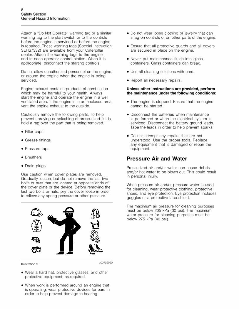
g00702020Illustration 5
• Wear a hard hat, protective glasses, and otherprotective equipment, as required.
• When work is performed around an engine thatis operating, wear protective devices for ears inorder to help prevent damage to hearing.
• Do not wear loose clothing or jewelry that cansnag on controls or on other parts of the engine.
• Ensure that all protective guards and all coversare secured in place on the engine.
• Never put maintenance fluids into glasscontainers. Glass containers can break.
• Use all cleaning solutions with care.
• Report all necessary repairs.
Unless other instructions are provided, performthe maintenance under the following conditions:
• The engine is stopped. Ensure that the enginecannot be started.
• Disconnect the batteries when maintenanceis performed or when the electrical system isserviced. Disconnect the battery ground leads.Tape the leads in order to help prevent sparks.
• Do not attempt any repairs that are notunderstood. Use the proper tools. Replaceany equipment that is damaged or repair theequipment.
Pressure Air and Water
Pressurized air and/or water can cause debrisand/or hot water to be blown out. This could resultin personal injury.
When pressure air and/or pressure water is usedfor cleaning, wear protective clothing, protectiveshoes, and eye protection. Eye protection includesgoggles or a protective face shield.
The maximum air pressure for cleaning purposesmust be below 205 kPa (30 psi). The maximumwater pressure for cleaning purposes must bebelow 275 kPa (40 psi).

9Safety Section
General Hazard Information
Fluid Penetration
g00687600Illustration 6
Always use a board or cardboard when you checkfor a leak. Leaking fluid that is under pressure canpenetrate body tissue. Fluid penetration can causeserious injury and possible death. A pin hole leakcan cause severe injury. If fluid is injected into yourskin, you must get treatment immediately. Seektreatment from a doctor that is familiar with this typeof injury.
Containing Fluid Spillage
Care must be taken in order to ensure that fluidsare contained during performance of inspection,maintenance, testing, adjusting and repair of theengine. Prepare to collect the fluid with suitablecontainers before opening any compartment ordisassembling any component containing fluids.
Refer to Special Publication, NENG2500, “Tools andShop Products Guide” for the following items:
• Tools that are suitable for collecting fluids andequipment that is suitable for collecting fluids
• Tools that are suitable for containing fluids andequipment that is suitable for containing fluids
Obey all local regulations for the disposal of liquids.
Asbestos Information
g00702022Illustration 7
Caterpillar equipment and replacement parts thatare shipped from Caterpillar are asbestos free.Caterpillar recommends the use of only genuineCaterpillar replacement parts. Use the followingguidelines when you handle any replacement partsthat contain asbestos or when you handle asbestosdebris.
Use caution. Avoid inhaling dust that might begenerated when you handle components thatcontain asbestos fibers. Inhaling this dust canbe hazardous to your health. The componentsthat may contain asbestos fibers are brake pads,brake bands, lining material, clutch plates, andsome gaskets. The asbestos that is used in thesecomponents is usually bound in a resin or sealed insome way. Normal handling is not hazardous unlessairborne dust that contains asbestos is generated.
If dust that may contain asbestos is present, thereare several guidelines that should be followed:
• Never use compressed air for cleaning.
• Avoid brushing materials that contain asbestos.
• Avoid grinding materials that contain asbestos.
• Use a wet method in order to clean up asbestosmaterials.
• A vacuum cleaner that is equipped with a highefficiency particulate air filter (HEPA) can also beused.
• Use exhaust ventilation on permanent machiningjobs.
• Wear an approved respirator if there is no otherway to control the dust.
10Safety SectionBurn Prevention
• Comply with applicable rules and regulationsfor the work place. In the United States, useOccupational Safety and Health Administration(OSHA) requirements. These OSHA requirementscan be found in “29 CFR 1910.1001”.
• Obey environmental regulations for the disposalof asbestos.
• Stay away from areas that might have asbestosparticles in the air.
Dispose of Waste Properly
g00706404Illustration 8
Improperly disposing of waste can threaten theenvironment. Potentially harmful fluids should bedisposed of according to local regulations.
Always use leakproof containers when you drainfluids. Do not pour waste onto the ground, down adrain, or into any source of water.
i01480768
Burn PreventionSMCS Code: 1000; 7405
Do not touch any part of an operating engine.Allow the engine to cool before any maintenanceis performed on the engine. Relieve all pressurein the air system, in the hydraulic system, in thelubrication system, in the fuel system, or in thecooling system before any lines, fittings or relateditems are disconnected.
Coolant
When the engine is at operating temperature, theengine coolant is hot. The coolant is also underpressure. The radiator and all lines to the heaters orto the engine contain hot coolant.
Any contact with hot coolant or with steamcan cause severe burns. Allow cooling systemcomponents to cool before the cooling system isdrained.
Check the coolant level after the engine hasstopped and the engine has been allowed to cool.
Ensure that the filler cap is cool before removingthe filler cap. The filler cap must be cool enoughto touch with a bare hand. Remove the filler capslowly in order to relieve pressure.
Cooling system conditioner contains alkali. Alkalican cause personal injury. Do not allow alkali tocontact the skin, the eyes, or the mouth.
Oils
Hot oil and hot lubricating components can causepersonal injury. Do not allow hot oil to contact theskin. Also, do not allow hot components to contactthe skin.
Batteries
Electrolyte is an acid. Electrolyte can causepersonal injury. Do not allow electrolyte to contactthe skin or the eyes. Always wear protective glassesfor servicing batteries. Wash hands after touchingthe batteries and connectors. Use of gloves isrecommended.
i01372254
Fire Prevention and ExplosionPreventionSMCS Code: 1000; 7405
g00704000Illustration 9
All fuels, most lubricants, and some coolant mixturesare flammable.

11Safety Section
Fire Prevention and Explosion Prevention
Flammable fluids that are leaking or spilled onto hotsurfaces or onto electrical components can causea fire. Fire may cause personal injury and propertydamage.
A flash fire may result if the covers for the enginecrankcase are removed within fifteen minutes afteran emergency shutdown.
Determine whether the engine will be operated inan environment that allows combustible gases to bedrawn into the air inlet system. These gases couldcause the engine to overspeed. Personal injury,property damage, or engine damage could result.
If the application involves the presence ofcombustible gases, consult your Caterpillar dealerfor additional information about suitable protectiondevices.
Remove all flammable materials such as fuel, oil,and debris from the engine. Do not allow anyflammable materials to accumulate on the engine.
Store fuels and lubricants in properly markedcontainers away from unauthorized persons. Storeoily rags and any flammable materials in protectivecontainers. Do not smoke in areas that are used forstoring flammable materials.
Do not expose the engine to any flame.
Exhaust shields (if equipped) protect hot exhaustcomponents from oil or fuel spray in case of a line,a tube, or a seal failure. Exhaust shields must beinstalled correctly.
Do not weld on lines or tanks that contain flammablefluids. Do not flame cut lines or tanks that containflammable fluid. Clean any such lines or tanksthoroughly with a nonflammable solvent prior towelding or flame cutting.
Wiring must be kept in good condition. All electricalwires must be properly routed and securelyattached. Check all electrical wires daily. Repair anywires that are loose or frayed before you operatethe engine. Clean all electrical connections andtighten all electrical connections.
Eliminate all wiring that is unattached orunnecessary. Do not use any wires or cables thatare smaller than the recommended gauge. Do notbypass any fuses and/or circuit breakers.
Arcing or sparking could cause a fire. Secureconnections, recommended wiring, and properlymaintained battery cables will help to prevent arcingor sparking.
Inspect all lines and hoses for wear or fordeterioration. The hoses must be properly routed.The lines and hoses must have adequate supportand secure clamps. Tighten all connections to therecommended torque. Leaks can cause fires.
Oil filters and fuel filters must be properly installed.The filter housings must be tightened to the propertorque.
g00704059Illustration 10
Use caution when you are refueling an engine. Donot smoke while you are refueling an engine. Donot refuel an engine near open flames or sparks.Always stop the engine before refueling.
g00704135Illustration 11

12Safety SectionCrushing Prevention and Cutting Prevention
Gases from a battery can explode. Keep any openflames or sparks away from the top of a battery. Donot smoke in battery charging areas.
Never check the battery charge by placing a metalobject across the terminal posts. Use a voltmeter ora hydrometer.
Improper jumper cable connections can causean explosion that can result in injury. Refer tothe Operation Section of this manual for specificinstructions.
Do not charge a frozen battery. This may causean explosion.
The batteries must be kept clean. The covers (ifequipped) must be kept on the cells. Use therecommended cables, connections, and batterybox covers when the engine is operated.
Fire Extinguisher
Make sure that a fire extinguisher is available. Befamiliar with the operation of the fire extinguisher.Inspect the fire extinguisher and service the fireextinguisher regularly. Obey the recommendationson the instruction plate.
Ether
Ether is flammable and poisonous.
Use ether in well ventilated areas. Do not smokewhile you are replacing an ether cylinder or whileyou are using an ether spray.
Do not store ether cylinders in living areas or in theengine compartment. Do not store ether cylindersin direct sunlight or in temperatures above 49 �C(120 �F). Keep ether cylinders away from openflames or sparks.
Dispose of used ether cylinders properly. Do notpuncture an ether cylinder. Keep ether cylindersaway from unauthorized personnel.
Do not spray ether into an engine if the engineis equipped with a thermal starting aid for coldweather starting.
Lines, Tubes and Hoses
Do not bend high pressure lines. Do not strike highpressure lines. Do not install any lines that are bentor damaged.
Repair any lines that are loose or damaged. Leakscan cause fires. Consult your Caterpillar dealer forrepair or for replacement parts.
Check lines, tubes and hoses carefully. Do notuse your bare hand to check for leaks. Use aboard or cardboard to check for leaks. Tighten allconnections to the recommended torque.
Replace the parts if any of the following conditionsare present:
• End fittings are damaged or leaking.
• Outer coverings are chafed or cut.
• Wires are exposed.
• Outer coverings are ballooning.
• Flexible part of the hoses are kinked.
• Outer covers have embedded armoring.
• End fittings are displaced.
Make sure that all clamps, guards, and heat shieldsare installed correctly. During engine operation, thiswill help to prevent vibration, rubbing against otherparts, and excessive heat.
i01359666
Crushing Prevention andCutting PreventionSMCS Code: 1000; 7405
Support the component properly when workbeneath the component is performed.
Unless other maintenance instructions are provided,never attempt adjustments while the engine isrunning.
Stay clear of all rotating parts and of all movingparts. Leave the guards in place until maintenanceis performed. After the maintenance is performed,reinstall the guards.
Keep objects away from moving fan blades. Thefan blades will throw objects or cut objects.
When objects are struck, wear protective glasses inorder to avoid injury to the eyes.
Chips or other debris may fly off objects whenobjects are struck. Before objects are struck, ensurethat no one will be injured by flying debris.

13Safety Section
Mounting and Dismounting
i01372247
Mounting and DismountingSMCS Code: 1000; 7405
Inspect the steps, the handholds, and the workarea before mounting the engine. Keep these itemsclean and keep these items in good repair.
Mount the engine and dismount the engine only atlocations that have steps and/or handholds. Do notclimb on the engine, and do not jump off the engine.
Face the engine in order to mount the engine ordismount the engine. Maintain a three-point contactwith the steps and handholds. Use two feet and onehand or use one foot and two hands. Do not useany controls as handholds.
Do not stand on components which cannot supportyour weight. Use an adequate ladder or use a workplatform. Secure the climbing equipment so that theequipment will not move.
Do not carry tools or supplies when you mount theengine or when you dismount the engine. Use ahand line to raise and lower tools or supplies.
i00911989
Before Starting EngineSMCS Code: 1000
Inspect the engine for potential hazards.
Before starting the engine, ensure that no one is on,underneath, or close to the engine. All protectiveguards and all protective covers must be installedif the engine must be started in order to performservice procedures. To help prevent an accidentthat is caused by parts in rotation, work around theparts carefully.
Do not bypass the automatic shutoff circuits. Do notdisable the automatic shutoff circuits. The circuitsare provided in order to help prevent personalinjury. The circuits are also provided in order to helpprevent engine damage.
On the initial start-up of a new engine or an enginethat has been serviced, prepare to stop the engineif an overspeed condition occurs. This may beaccomplished by shutting off the fuel supply tothe engine and/or shutting off the air supply to theengine.
See the Service Manual for repairs and foradjustments.
i00910470
Engine StartingSMCS Code: 1000
If a warning tag is attached to the engine startswitch or to the controls, do not start the engineor move the controls. Also, do not disengagethe parking brakes. Consult with the person thatattached the warning tag before the engine isstarted.
All protective guards and all protective covers mustbe installed if the engine must be started in orderto perform service procedures. To help prevent anaccident that is caused by parts in rotation, workaround the parts carefully.
Start the engine from the operator’s station (cab).Never short across the starting motor terminals orthe batteries. This could bypass the engine neutralstart system and/or the electrical system could bedamaged.
Always start the engine according to the procedurethat is described in the Operation and MaintenanceManual, “Engine Starting” topic (Operation Section).Knowing the correct procedure will help to preventmajor damage to the engine components. Knowingthe procedure will also help to prevent personalinjury.
To ensure that the jacket water heater (if equipped)and/or the lube oil heater (if equipped) is workingproperly, check the water temperature gaugeand the oil temperature gauge during the heateroperation.
Engine exhaust contains products of combustionthat can be harmful to your health. Always start theengine and operate the engine in a well ventilatedarea. If the engine is started in an enclosed area,vent the engine exhaust to the outside.
Ether
Ether is poisonous and flammable. Do not inhaleether, and do not allow ether to contact the skin.Personal injury could result. Do not smoke whileether cylinders are changed. Use ether in wellventilated areas.
Keep ether cylinders out of the reach ofunauthorized persons. Store ether cylinders inauthorized storage areas only. Do not store ethercylinders in direct sunlight or at temperatures above39 �C (102 �F). Discard the ether cylinders in a safeplace. Do not puncture the ether cylinders. Do notburn the ether cylinders.
14Safety SectionEngine Stopping
i01462046
Engine StoppingSMCS Code: 1000
Stop the engine according to the procedure inthe Operation and Maintenance Manual, “EngineStopping (Operation Section)” in order to avoidoverheating of the engine and accelerated wear ofthe engine components.
Use the Emergency Stop Button (if equipped)ONLY in an emergency situation. Do not use theEmergency Stop Button for normal engine stopping.After an emergency stop, DO NOT start the engineuntil the problem that caused the emergency stophas been corrected.
Stop the engine if an overspeed condition occursduring the initial start-up of a new engine or anengine that has been overhauled. This may beaccomplished by shutting off the fuel supply tothe engine and/or shutting off the air supply to theengine.
To stop an electronically controlled engine, cut thepower to the engine.
i01489749
Electrical SystemSMCS Code: 1000; 1400
Never disconnect any charging unit circuit or batterycircuit cable from the battery when the charging unitis operating. A spark can cause the combustiblegases that are produced by some batteries to ignite.
To help prevent sparks from igniting combustiblegases that are produced by some batteries, thenegative “−” jump start cable should be connectedlast from the external power source to the negative“−” terminal of the starting motor. If the startingmotor is not equipped with a negative “−” terminal,connect the jump start cable to the engine block.
Check the electrical wires daily for wires that areloose or frayed. Tighten all loose electrical wiresbefore the engine is started. Repair all frayedelectrical wires before the engine is started. Seethe Operation and Maintenance Manual for specificstarting instructions.
Grounding Practices
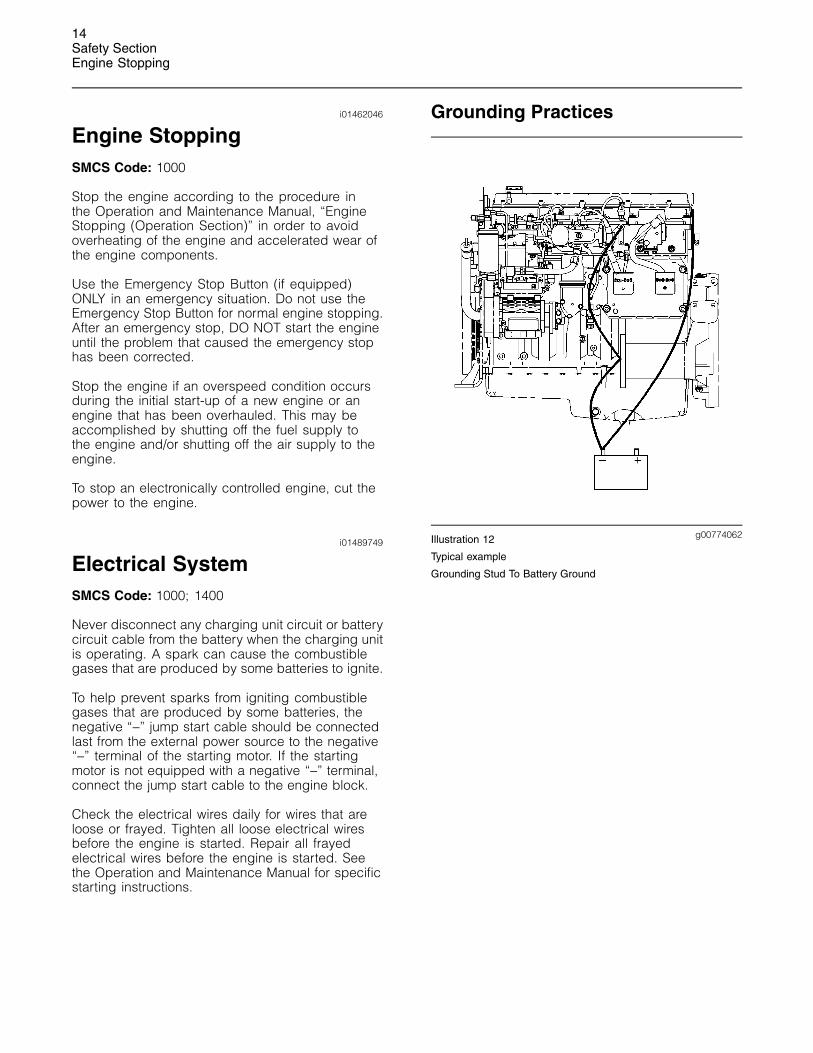
g00774062Illustration 12
Typical example
Grounding Stud To Battery Ground

15Safety Section
Engine Electronics
g00774088Illustration 13
Typical example
Alternate Grounding Stud To Battery Ground
Proper grounding for the engine electrical systemis necessary for optimum engine performanceand reliability. Improper grounding will result inuncontrolled electrical circuit paths and in unreliableelectrical circuit paths.
Uncontrolled electrical circuit paths can result indamage to main bearings, to crankshaft bearingjournal surfaces, and to aluminum components.
Engines that are installed without engine-to-frameground straps can be damaged by electricaldischarge.
To ensure that the engine and the engine electricalsystems function properly, an engine-to-frameground strap with a direct path to the battery mustbe used. This path may be provided by way of astarting motor ground, a starting motor ground tothe frame, or a direct engine ground to the frame.
All grounds should be tight and free of corrosion.The engine alternator must be grounded to thenegative “-” battery terminal with a wire that isadequate to handle the full charging current of thealternator.
i01563743
Engine ElectronicsSMCS Code: 1000; 1400; 1900
Tampering with the electronic system installationor the OEM wiring installation can be dangerousand could result in personal injury or death and/orengine damage.
This engine has a comprehensive, programmableEngine Monitoring System. The Engine ControlModule (ECM) has the ability to monitor theengine operating conditions. If any of the engineparameters extend outside an allowable range, theECM will initiate an immediate action.
The following actions are available for enginemonitoring control: WARNING, DERATE, andSHUTDOWN. These engine monitoring modes havethe ability to limit engine speed and/or the enginepower.
Many of the parameters that are monitored bythe ECM can be programmed for the enginemonitoring functions. The following parameters canbe monitored as a part of the Engine MonitoringSystem:
• Operating Altitude
• Engine Coolant Level
• Engine Coolant Temperature
• Engine Oil Pressure
• Engine Speed
• Fuel Temperature
• Intake Manifold Air Temperature
• System Voltage
The Engine Monitoring package can vary fordifferent engine models and different engineapplications. However, the monitoring system andthe engine monitoring control will be similar for allengines.

16Safety SectionEngine Electronics
Note: Many of the engine control systems anddisplay modules that are available for CaterpillarEngines will work in unison with the EngineMonitoring System. Together, the two controls willprovide the engine monitoring function for thespecific engine application. Refer to the ElectronicTroubleshooting Manual for more information on theEngine Monitoring System.

17Product Information Section
General Information
Product InformationSection
General Information
i01456258
Welding on Engines withElectronic ControlsSMCS Code: 1000
NOTICEBecause the strength of the frame may decrease,some manufacturers do not recommend weldingonto a chassis frame or rail. Consult the OEM ofthe equipment or your Caterpillar dealer regardingwelding on a chassis frame or rail.
Proper welding procedures are necessary in orderto avoid damage to the engine’s ECM, sensors,and associated components. When possible,remove the component from the unit and thenweld the component. If removal of the componentis not possible, the following procedure must befollowed when you weld on a unit that is equippedwith a Caterpillar Electronic Engine. The followingprocedure is considered to be the safest procedureto weld on a component. This procedure shouldprovide a minimum risk of damage to electroniccomponents.
NOTICEDo not ground the welder to electrical componentssuch as the ECM or sensors. Improper grounding cancause damage to the drive train bearings, hydrauliccomponents, electrical components, and other com-ponents.
Clamp the ground cable from the welder to the com-ponent that will be welded. Place the clamp as closeas possible to the weld. This will help reduce the pos-sibility of damage.
1. Stop the engine. Turn the switched power to theOFF position.
2. Disconnect the negative battery cable fromthe battery. If a battery disconnect switch isprovided, open the switch.
3. Disconnect the J1/P1 and J2/P2 connectors fromthe ECM. Move the harness to a position that willnot allow the harness to accidentally move backand make contact with any of the ECM pins.
g00765012Illustration 14
Use the example above. The current flow from the welder tothe ground clamp of the welder will not cause damage to anyassociated components.
(1) Engine(2) Welding rod(3) Keyswitch in the OFF position(4) Battery disconnect switch in the open position(5) Disconnected battery cables(6) Battery(7) Electrical/Electronic component(8) Maximum distance between the component that is being
welded and any electrical/electronic component(9) The component that is being welded(10) Current path of the welder(11) Ground clamp for the welder
4. Connect the welding ground cable directly tothe part that will be welded. Place the groundcable as close as possible to the weld in order toreduce the possibility of welding current damageto bearings, hydraulic components, electricalcomponents, and ground straps.
Note: If electrical/electronic components are usedas a ground for the welder, or electrical/electroniccomponents are located between the welder groundand the weld, current flow from the welder couldseverely damage the component.
5. Protect the wiring harness from welding debrisand spatter.
6. Use standard welding practices to weld thematerials.

18Product Information SectionModel Views
Model Views
i01474848
Model View IllustrationsSMCS Code: 1000
g00770182Illustration 15
Right Side View
(1) Valve mechanism cover(2) Turbocharger(3) Engine oil filler cap(4) Water temperature regulator housing(5) Exhaust manifold(6) Water pump(7) Flywheel housing(8) Engine oil pan(9) Engine oil filter(10) Vibration damper and crankshaft pulley
g00774521Illustration 16
Left Side View
(11) Engine oil filler(12) Electronic Control Module (ECM)(13) Air compressor(14) Oil drain plug
i01477858
Engine DescriptionSMCS Code: 1000
The Caterpillar C-9 Industrial Engine has thefollowing characteristics:
• In-Line 6 cylinder
• Four stroke cycle
• Hydraulically Actuated Electronic Unit Injection(HEUI)
• Turbocharged
• Air-to-air aftercooled
Engine Specifications
Note: The front end of the engine is opposite theflywheel end of the engine. The left and the rightsides of the engine are determined from the flywheelend. The number 1 cylinder is the front cylinder.

19Product Information Section
Model Views
g00609479Illustration 17
Cylinder and valve location
(A) Exhaust valve(B) Inlet valve
Table 1
C-9 Engine Specifications
Arrangement andCylinders In-Line 6 cylinder
Bore 112.0 mm (4.41 inch)
Stroke 149.0 mm (5.87 inch)
Aspiration ATAAC(1)
Displacement 8.8 L (537 in3)
Firing Order 1-5-3-6-2-4
Rotation (flywheel end) Counterclockwise
Valve Lash (inlet) 0.38 mm (0.015 inch)
Valve Lash (exhaust) 0.64 mm (0.025 inch)
(1) Air-to-air aftercooled
Electronic Engine Features
The Caterpillar C-9 Engine is designed for electroniccontrols. The integral on board computer controlsthe operation of the engine. Current operatingconditions are monitored. The Electronic ControlModule (ECM) controls the response of the engineto these conditions and to the demands of theoperator. These conditions and operator demandsdetermine the precise control of fuel injection by theECM. The electronic engine control system providesthe following features:
• Engine speed governor
• Automatic air/fuel ratio control
• Torque rise shaping
• Injection timing control
• System diagnostics
For more information on electronic engine features,refer to the Operation and Maintenance Manual,“Engine Features and Controls” topic (OperationSection).
Additional Features
The following additional features provide increasedengine fuel economy and serviceability:
• Cold starting capability
• Tampering detection
• Diagnostics
Hydraulic Electronic Unit Injectors
Hydraulically Actuated Electronic Unit Injectors(HEUI) perform the following functions:
• Pump the fuel.
• Meter the fuel.
• Time the fuel injection.
The unit injectors are controlled by the ECM whichuses the camshaft position and the engine speedsignals from the engine speed/timing sensors andthe inlet air pressure sensors. The engine’s ratedrpm is identified on the Information Plate.
Engine Diagnostics
The engine has built-in diagnostics in order toensure that all of the components are functioningproperly. In the event of a deviation from theprogrammed limits, the operator will be alertedto the condition by a “DIAGNOSTIC” lamp thatis mounted on the dashboard. Under certainconditions, the engine horsepower and the vehiclespeed may be limited. A Caterpillar electronicservice tool may be used to display the diagnosticcode.
There are three types of diagnostic codes: active,logged, and event.
Most of the diagnostic codes are logged and storedin the ECM. For additional information, refer tothe Operation and Maintenance Manual, “EngineDiagnostics” topic (Operation Section).
The ECM provides an electronic governor thatcontrols the injector output in order to maintain thedesired engine rpm. The functionality of electronicgovernor is similar to the Caterpillar mechanicalgovernor, but the electronic governor includesadditional features.

20Product Information SectionModel Views
Engine Cooling and Lubrication
The cooling system consists of the followingcomponents:
• Centrifugal pump that is driven by belts
• Water temperature regulator which regulates theengine coolant temperature
• Oil cooler and radiator which incorporates a shuntsystem
The engine lubricating oil that is supplied is cooled.The engine lubricating oil is also filtered. Bypassvalves provide unrestricted flow of lubrication oilto the engine components during the followingconditions:
• High oil viscosity
• Plugged oil cooler or plugged oil filter elements(paper cartridge)
Engine Service Life
Engine efficiency and maximum utilization of engineperformance depend on the adherence to properoperation and maintenance recommendations. Inaddition, use recommended fuels, coolants andlubricants. Use the Operation and MaintenanceManual as a guide for required engine maintenance.
Expected engine life is generally predictedby the average power that is demanded. Theaverage power that is demanded is based on fuelconsumption of the engine over a period of time.Reduced hours of operation at full throttle and/oroperating at reduced throttle settings result in alower average power demand. Reduced hoursof operation will increase the length of operatingtime before an engine overhaul is required. Formore information, refer to the Operation andMaintenance Manual, “Overhaul Considerations”topic (Maintenance Section).
Aftermarket Products andCaterpillar Engines
NOTICEIn order to maximize fuel system life and preventpremature wear out from abrasive particles in thefuel, a two micron absolute high efficiency fuel filteris required for all Caterpillar Electronic Unit Injectors.Caterpillar High Efficiency Fuel Filters meet theserequirements. Consult your Caterpillar dealer for theproper part numbers.
When auxiliary devices, accessories, orconsumables (filters, additives, catalysts, etc) whichare made by other manufacturers are used onCaterpillar products, the Caterpillar warranty is notaffected simply because of such use.
However, failures that result from the installationor use of other manufacturers’ devices,accessories, or consumables are NOT Caterpillardefects. Therefore, the defects are NOT coveredunder the Caterpillar warranty.
Welding and Caterpillar ElectronicEngines
NOTICEBecause the strength of the frame may decrease,some manufacturers do not recommend weldingonto a chassis frame or rail. Consult the OEM ofthe equipment or your Caterpillar dealer regardingwelding on a chassis frame or rail.
To help avoid damage to the electronic controls,proper welding procedures are necessary. Beforewelding on an engine that is equipped with anelectronic engine, observe the following precautions:
1. Turn off the engine. Place the key start switch inthe OFF position.
2. If the machine has a battery disconnect switch,open the switch. Otherwise, disconnect thenegative “-” battery cable from the battery of thevehicle.
NOTICEDo not ground the welder to electrical componentssuch as the ECM or sensors. Improper grounding cancause damage to the drive train bearings, hydrauliccomponents, electrical components, and other com-ponents.
Clamp the ground cable from the welder to the com-ponent that will be welded. Place the clamp as closeas possible to the weld. This will help reduce the pos-sibility of damage.
3. Clamp the ground cable from the welder to thecomponent that will be welded. Place the clampas close as possible to the weld.
4. Protect wiring harnesses from welding debrisand spatter. Use proper welding procedures.

21Product Information Section
Product Identification Information
Product IdentificationInformation
i01028428
Engine IdentificationSMCS Code: 1000
Caterpillar engines are identified with serialnumbers, with performance specification numbers,and with arrangement numbers. In some of thecases, modification numbers are used. Thesenumbers are shown on the Serial Number Plateand the Information Plate that are mounted on theengine.
Caterpillar dealers need these numbers in order todetermine the components that were included withthe engine. This permits accurate identification ofreplacement part numbers.
i01461841
Serial Number PlateSMCS Code: 1000
g00764267Illustration 18
The Serial Number Plate is located on the right sideof the cylinder block near the rear of the engine.
The following information is stamped on the SerialNumber Plate: engine serial number, engine model,and arrangement number.
i01484593
Information PlateSMCS Code: 1000
g00764335Illustration 19
The Information Plate is on the valve cover. Thefollowing information is on the Information Plate:engine serial number, engine model, enginearrangement number, maximum altitude of theengine that is necessary to achieve the rated power,horsepower, high idle, full load rpm, fuel settings,and other information.
i00610276
Reference NumbersSMCS Code: 1000
Information for the following items may be neededto order parts. Locate the information for yourengine. Record the information on the appropriatespace. Make a copy of this list for a record. Retainthe information for future reference.
Record for Reference
Engine Model ______________________________________________
Engine Serial No. __________________________________________
Engine Arrangement No. ________________________________
Modification No. ___________________________________________
Engine Low Idle rpm _____________________________________
Engine Full Load rpm ____________________________________
Performance Specification No. _________________________
Primary Fuel Filter No. ___________________________________
Water Separator Element No. __________________________
22Product Information SectionProduct Identification Information
Secondary Fuel Filter Element No. ____________________
Lubrication Oil Filter Element No. _____________________
Auxiliary Oil Filter Element No. _________________________
Supplemental Coolant Additive MaintenanceElement No. (Optional) ___________________________________
Total Lubrication System Capacity ____________________
Total Cooling System Capacity ________________________
Air Cleaner Element No. _________________________________
Fan Drive Belt No. ________________________________________
Alternator Belt No. ________________________________________
i01542360
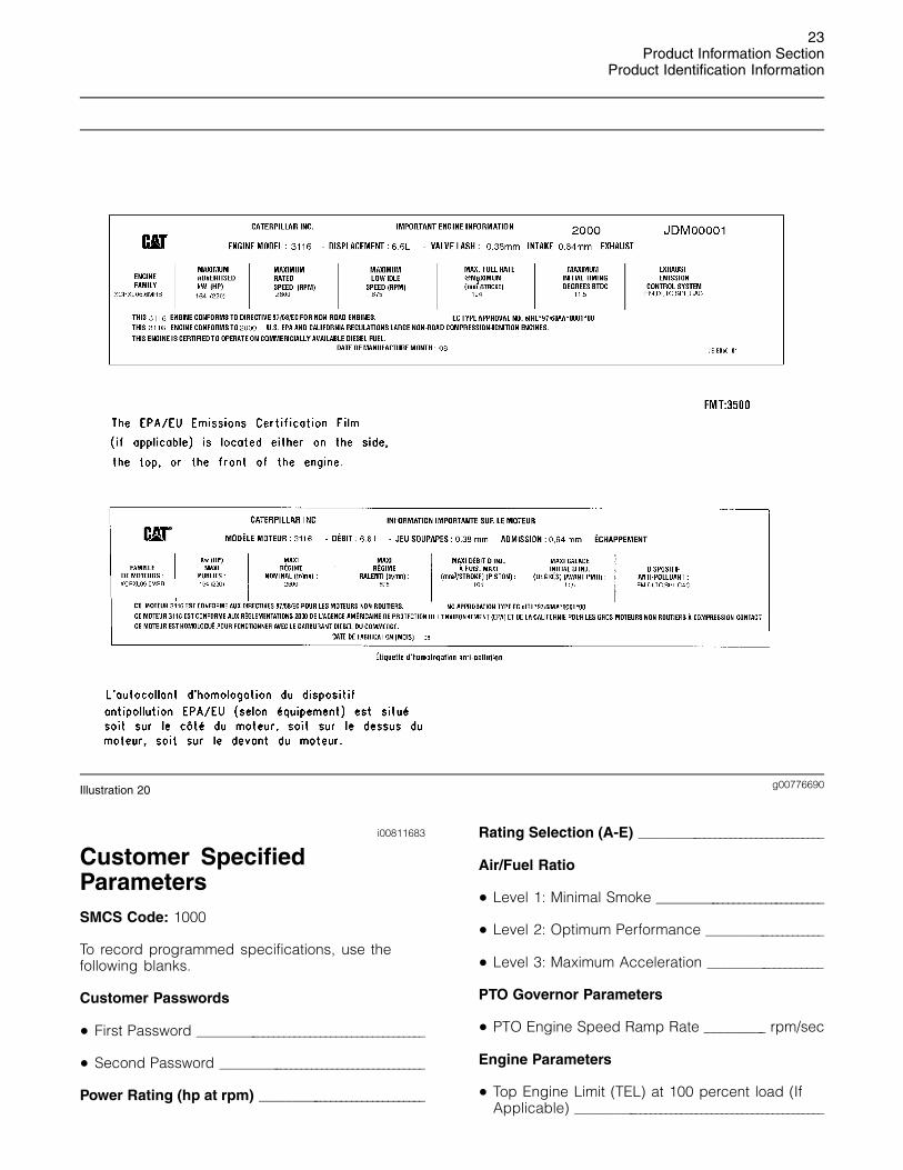
Emissions Certification FilmSMCS Code: 1000; 7405
Note: This information is pertinent in the UnitedStates and in Canada.
A typical example is shown.
23Product Information Section
Product Identification Information
g00776690Illustration 20
i00811683
Customer SpecifiedParametersSMCS Code: 1000
To record programmed specifications, use thefollowing blanks.
Customer Passwords
• First Password __________________________________________
• Second Password ______________________________________
Power Rating (hp at rpm) ______________________________
Rating Selection (A-E) __________________________________
Air/Fuel Ratio
• Level 1: Minimal Smoke ______________________________
• Level 2: Optimum Performance _____________________
• Level 3: Maximum Acceleration ____________________
PTO Governor Parameters
• PTO Engine Speed Ramp Rate __________ rpm/sec
Engine Parameters
• Top Engine Limit (TEL) at 100 percent load (IfApplicable) _______________________________________________

24Product Information SectionProduct Identification Information
• Torque Limit ______________________________________________
• High Idle (If Applicable) ______________________________
• Low Idle __________________________________________________
• Intermediate Speed ____________________________________
Engine Monitoring Mode
• “OFF” ______________________________________________________
• “Warning” _________________________________________________
• “Warning/Derate” _______________________________________
• “Warning/Derate/Shutdown” _________________________
• “Coolant Level Sensor Enable/Disable” ___________
• “Fuel Pressure Sensor Enable/Disable” ___________
• “Inlet Manifold Air Temperature SensorEnable/Disable” _________________________________________
Equipment ID
Maintenance Indicator
• Manual-Hours
• Auto-Hours
• Manual-Fuel
• Auto-Fuel
Auxiliary Pressure
• High Warning Set Point _______________________________
Auxiliary Temperature
• High Warning Set Point _______________________________
25Operation Section
Engine Lifting and Storage
Operation Section
Engine Lifting and Storage
i01028344
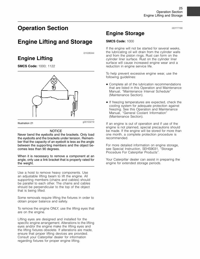
Engine LiftingSMCS Code: 1000; 1122
g00103219Illustration 21
NOTICENever bend the eyebolts and the brackets. Only loadthe eyebolts and the brackets under tension. Remem-ber that the capacity of an eyebolt is less as the anglebetween the supporting members and the object be-comes less than 90 degrees.
When it is necessary to remove a component at anangle, only use a link bracket that is properly rated forthe weight.
Use a hoist to remove heavy components. Usean adjustable lifting beam to lift the engine. Allsupporting members (chains and cables) shouldbe parallel to each other. The chains and cablesshould be perpendicular to the top of the objectthat is being lifted.
Some removals require lifting the fixtures in order toobtain proper balance and safety.
To remove the engine ONLY, use the lifting eyes thatare on the engine.
Lifting eyes are designed and installed for thespecific engine arrangement. Alterations to the liftingeyes and/or the engine make the lifting eyes andthe lifting fixtures obsolete. If alterations are made,ensure that proper lifting devices are provided.Consult your Caterpillar dealer for informationregarding fixtures for proper engine lifting.
i00777190
Engine StorageSMCS Code: 1000
If the engine will not be started for several weeks,the lubricating oil will drain from the cylinder wallsand from the piston rings. Rust can form on thecylinder liner surface. Rust on the cylinder linersurface will cause increased engine wear and areduction in engine service life.
To help prevent excessive engine wear, use thefollowing guidelines:
• Complete all of the lubrication recommendationsthat are listed in this Operation and MaintenanceManual, “Maintenance Interval Schedule”(Maintenance Section).
• If freezing temperatures are expected, check thecooling system for adequate protection againstfreezing. See this Operation and MaintenanceManual, “General Coolant Information”(Maintenance Section).
If an engine is out of operation and if use of theengine is not planned, special precautions shouldbe made. If the engine will be stored for more thanone month, a complete protection procedure isrecommended.
For more detailed information on engine storage,see Special Instruction, SEHS9031, “StorageProcedure For Caterpillar Products”.
Your Caterpillar dealer can assist in preparing theengine for extended storage periods.

26Operation SectionGauges and Indicators
Gauges and Indicators
i01465281
Gauges and IndicatorsSMCS Code: 1900; 7450
Your engine may not have the same gauges or all ofthe gauges that are described. For more informationabout the gauge package, see the literature thatis provided by the OEM.
Gauges provide indications of engine performance.Ensure that the gauges are in good working order.Determine the normal operating range by observingthe gauges over a period of time.
Noticeable changes in gauge readings indicatepotential gauge or engine problems. Problems mayalso be indicated by gauge readings that changeeven if the readings are within specifications.Determine the cause of any significant changein the readings. Then, correct any cause of anysignificant change in the readings. Consult yourCaterpillar dealer for assistance.
Caterpillar requires one lamp in addition tothe gauge package that is normally provided.The “Diagnostic” lamp is yellow or amber. The“Diagnostic” lamp will communicate the status ofthe engine’s electronic system. The optional red“Warning” lamp is also available. This red “Warning”lamp warns the operator of engine problems.
The following conditions are some examples of theengine problems:
• Low oil pressure
• High coolant temperature
• Low coolant level
• High inlet air temperature
Engine Oil Pressure – Typical oil pressurefor an engine at rated speed withSAE 10W30 or with SAE 15W40 is
240 to 480 kPa (35 to 70 psi).
A lower oil pressure is normal at low idle. If the loadis stable and the gauge reading changes, performthe following procedure:
1. Remove the load.
2. Reduce engine speed to low idle.
3. Check the oil level. Maintain the oil level at theproper amount.
If the gauge continues to fluctuate, consult yourCaterpillar dealer.
The diagnostic lamp will turn on if the oil pressuredrops below 35 kPa (5 psi) at low idle rpm. Thediagnostic code will be logged in the Engine ControlModule (ECM).
Engine Oil Temperature – This gaugeindicates the engine oil temperature. Anoil temperature that is higher than normal
indicates a heat problem in the lubrication systemand/or the cooling system. This problem candamage the cylinder heads, the cylinder liners, thepistons, and the crankshaft bearings.
Jacket Water Coolant Temperature –Typical temperature range is 88 to 102 �C(190 to 215 �F). The maximum allowable
temperature with the pressurized cooling system is105 �C (220 �F). Higher temperatures may occurunder certain conditions. The water temperaturereading may vary according to load. The readingshould never exceed the boiling point for thepressurized system that is being used.
If the engine is operating above the normal rangeor steam becomes apparent, perform the followingprocedure:
1. Reduce the load and the engine rpm.
2. Inspect the cooling system for leaks.
3. Determine if the engine must be shut downimmediately or if the engine can be cooled byreducing the load.
Pressurized System: Hot coolant can cause seri-ous burns. To open the cooling system filler cap,stop the engine and wait until the cooling systemcomponents are cool. Loosen the cooling systempressure cap slowly in order to relieve the pres-sure.
4. Check the coolant level.
Tachometer – This gauge indicates enginespeed. When the throttle control lever ismoved to the full throttle position without
load, the engine is running at high idle. The engineis running at the full load rpm when the throttlecontrol lever is at the full throttle position withmaximum rated load.

27Operation Section
Gauges and Indicators
Note: The default high idle rpm and the full loadrpm are stamped on the Information Plate.
Ammeter – This gauge indicates theamount of charge or of discharge in thebattery charging circuit. Operation of the
indicator should be to the right side of “0”(zero).
Service Hour Meter – This gauge indicatesthe total number of clock hours of engineoperation. Hours of operation are logged
in the ECM. A service tool is needed to retrieve thehours from the ECM. A Service Hour Meter may beinstalled on the engine.
Fuel Pressure – This gauge indicates fuelpressure to the electronic unit injectorsfrom the fuel filter. The indicator should
indicate the “NORMAL” range. A decrease in fuelpressure usually indicates a plugged fuel filter.
Fuel Level – This gauge indicates thelevel of fuel in the fuel tank. The fuel levelgauge registers the fuel level only when
the ignition switch is in the ON position.
i01518477
Engine Monitoring System(EMS)SMCS Code: 7490
g00788015Illustration 22
(1) Main unit (2) Tachometer (unit) (3) Quad gauge

28Operation SectionGauges and Indicators
The Caterpillar Engine Monitoring System (EMS) isan option. The engine parameters are displayed inboth digital display and analog. The EMS display isfor electronically controlled engines.
The EMS includes three individual gauge units. Theunits can be installed in various combinations. Themain unit must be used if any of the units are used.
Refer to the EMS Operator’s Guide, LEXH7530 foradditional information. For information on installationand troubleshooting, refer to Installation Guide,SENR1025.
EMS Main Unit
g00595165Illustration 23
(4) Engine oil pressure(5) Engine coolant temperature(6) Fuel pressure(7) Inlet manifold temperature(8) Fuel temperature(9) Engine coolant level(10) Battery voltage(11) Active engine derate(12) Auxiliary temperature(13) Auxiliary pressure
The Engine Monitoring System provides warninglamps. Refer to Illustration 23. The EngineMonitoring System provides a LCD display forengine parameters. When the scroll switch isdepressed, the parameters will scroll on the screen.The EMS displays the real time value for theparameter that is selected. The default is enginespeed.
The parameters are abbreviated on the LCDdisplay. Table 2 lists the parameters.
Table 2
Abbreviation Parameter
Spd Engine Speed
GA-1 Engine Oil Pressure
GA-2 Coolant Temperature
GA-3 Battery Voltage
GA-4 Fuel Pressure
Boost Boost Pressure
IAirT Inlet Air Temperature
FuelT Fuel Temperature
AccrP Auxiliary Pressure
AccrT Auxiliary Temperature
Fuel Fuel Rate
Hrs Engine Hours
Load Percent of Engine Load(speed and derate)
Note: For detailed information on the exactparameters for your engine, refer to the Operationand Maintenance Manual, “Gauges and Indicators”.
Quad Gauge Unit
g00595166Illustration 24
(14) Engine oil pressure(15) Engine coolant temperature(16) Battery voltage(17) Fuel pressure
The quad gauge unit displays the followinginformation: engine oil pressure, engine coolanttemperature, battery voltage, and fuel pressure
29Operation Section
Gauges and Indicators
Note: The gauge needles may not always return tozero position when the engine is not running.
Note: For detailed information on the exactparameters for your engine, refer to the Operationand Maintenance Manual, “Gauges and Indicators”.
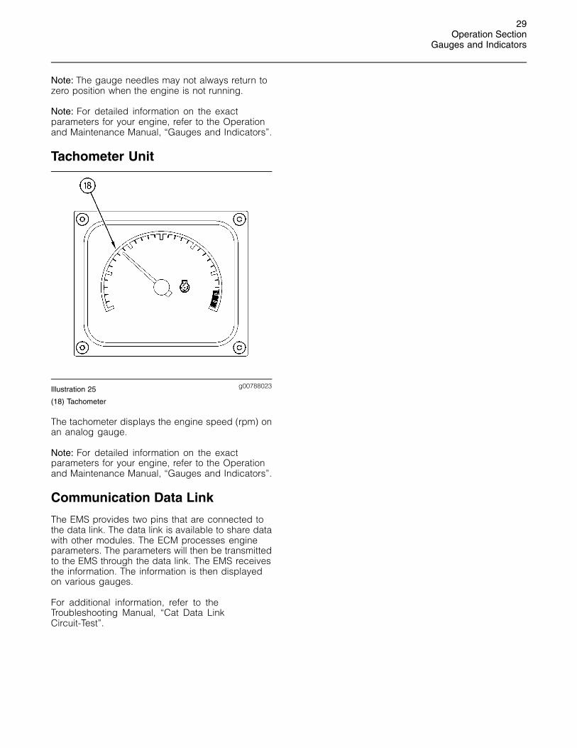
Tachometer Unit
g00788023Illustration 25
(18) Tachometer
The tachometer displays the engine speed (rpm) onan analog gauge.
Note: For detailed information on the exactparameters for your engine, refer to the Operationand Maintenance Manual, “Gauges and Indicators”.
Communication Data Link
The EMS provides two pins that are connected tothe data link. The data link is available to share datawith other modules. The ECM processes engineparameters. The parameters will then be transmittedto the EMS through the data link. The EMS receivesthe information. The information is then displayedon various gauges.
For additional information, refer to theTroubleshooting Manual, “Cat Data LinkCircuit-Test”.

30Operation SectionEngine Features and Controls
Engine Features andControls
i01503649
Sensors and ElectricalComponentsSMCS Code: 1900; 7400
Sensor Locations
Illustration 26 shows the typical locations of thesensors for a C-9 Industrial Engine. Specific enginesmay appear different from the illustration due todifferences in applications.
g00779441Illustration 26
(1) Coolant Temperature Sensor(2) Injection Actuation Pressure Control
Valve(IAPCV)(3) Inlet Air Heater Relay(4) Turbocharger Outlet Pressure Sensor(5) Inlet Air Temperature Sensor(6) Timing Calibration Probe(7) Engine Service Connector J63
(8) High Pressure Engine Oil TemperatureSensor
(9) Primary Engine Speed/Timing Sensor(10) Secondary Engine Speed/Timing
Sensor(11) Injection Actuation Pressure Sensor(12) Fuel Pressure Sensor
(13) High Pressure Engine Oil TemperatureSensor
(14) Engine Oil Pressure Sensor(15) ECM connector J2/P2(16) ECM connector J1/P1(17) Oil Grade Detection Plug(18) Atmospheric Pressure Sensor

31Operation Section
Engine Features and Controls
Failure of Sensors
All Sensors
A failure of any of the sensors may be caused byone of the following malfunctions:
• Sensor output is open.
• Sensor output is shorted to “- battery” or “+battery”.
• Measured reading of the sensor is out ofspecification.
Programmable Monitoring System(PMS)
The Programmable Monitoring System determinesthe level of action that is taken by the ECM inresponse to a condition that can damage theengine. These conditions are identified by theECM from the signals that are produced from thefollowing sensors.
• Inlet Air Temperature Sensor
• Engine Coolant Temperature Sensor
• Engine Oil Pressure Sensor
• Engine Speed/Timing Sensors
• Fuel Pressure Sensor
• Coolant Level Sensor
• Atmospheric Pressure Sensor
Atmospheric Pressure Sensor
Atmospheric pressure sensor (18) measuresbarometric pressure. A signal is sent to theElectronic Control Module (ECM).
Table 3
Atmospheric Pressure Sensor
Operating pressurerange 0 to 116 kPa (0 to 16.8 psi)
Turbocharger Outlet PressureSensor
Turbocharger outlet pressure sensor (4) providesa signal which corresponds to turbocharger outletpressure to the ECM. The air/fuel ratio control utilizesthe actual engine speed and the turbocharger outletpressure in order to control the transient smokelevel. The ECM can control injection timing and theamount of fuel that is injected. When the throttle isincreased and when the engine demands more fuel,the fuel limit is controlled in order to reduce overallsmoke levels of the engine exhaust.
Failure of the Turbocharger OutletPressure Sensor
The ECM will detect failure of the turbocharger outletpressure sensor. The operator will be warned of theproblem through the diagnostic lamp. The strategiesthat are related to the boost will be disabled. Enginepower will be severely reduced in the event of afailure of the turbocharger outlet pressure sensor. Afailure of the turbocharger outlet pressure sensorwill not cause a shutdown of the engine.
Coolant Temperature Sensor
Coolant temperature sensor (1) monitors enginecoolant temperature. The output of the ECM canindicate a high coolant temperature through a relayor a lamp. The coolant temperature sensor is usedby the ECM to determine initiation of the Cold StartCondition.
Table 4
Coolant Temperature Sensor
Activation temperature for the highcoolant temperature fault 103�C (217�F)
Activation temperature for the veryhigh coolant temperature fault 106�C (229�F)
Failure of the Coolant TemperatureSensor
The ECM will detect a failure of the coolanttemperature sensor. The diagnostic lamp willwarn the operator about the status of the coolanttemperature sensor. A failure of the coolanttemperature sensor will not cause a shutdown ofthe engine or any horsepower change.

32Operation SectionEngine Features and Controls
Engine Oil Pressure Sensor
Engine oil pressure sensor (14) is an absolutepressure sensor that measures the engine oilpressure in the main oil gallery. The engine oilpressure sensor detects engine oil pressure fordiagnostic purposes. The engine oil pressuresensor sends a signal to the ECM.
Table 5
Engine Oil Pressure Sensor
Operating pressurerange 0 to 690 kPa (0 to 100 psi)
Low Oil Pressure Warning
The setpoint is dependent upon the engine speed.The fault will be active and logged only if the enginehas been running for more than 15 seconds.
Very Low Oil Pressure Warning
The very low oil pressure setpoint is dependentupon the engine speed. If the DERATE mode of theengine monitoring system is selected, the ECM willderate the engine power. The engine horsepowerwill be limited.
Failure of the Engine Oil Pressure Sensor
The ECM will detect failure of the engine oilpressure sensor. The diagnostic lamp warns theuser about the status of the engine oil pressuresensor. The engine oil pressure related strategieswill be disabled in the event of a failure of theengine oil pressure sensor. A failure of the engineoil pressure sensor will not cause a shutdown of theengine or any horsepower change.
Engine Oil Temperature Sensor
Engine oil temperature sensor (8) monitors thetemperature of the engine oil. The ECM uses theinformation from the engine oil temperature sensorin order to adjust the timing of the fuel injection andthe pressure of the fuel injection.
Table 6
Engine Oil Temperature Sensor
Operating temperaturerange −40 to 120�C (−40 to 258�F)
Crankshaft Position Sensor andCamshaft Position Sensor
If the ECM does not receive a signal from crankshaftposition sensor (10), the “DIAGNOSTIC” lampwill indicate a diagnostic fault code which will belogged in the ECM memory.
If the ECM does not receive a signal from theprimary speed/timing sensor, the ECM will read thesignal from the secondary speed/timing sensor. TheECM continually checks in order to determine ifthere is a signal from both sensors. If either sensorfails, the faulty sensor should be replaced.
Intermittent failure of the sensors will cause erraticengine control.
Injection Actuation PressureSensor
Injection actuation pressure sensor (2) providesa signal of the injection actuation pressure to theECM. The ECM modifies the current to the injectionactuation pressure control valve (not shown) inorder to control the injection actuation pressure. Thedesired actuation pressure is based on the followingengine parameters: quantity of fuel, injection timing,engine speed, and engine operating mode.
Inlet Air Temperature Sensor
Inlet air temperature sensor (5) measures the inletair temperature. A signal is sent to the ElectronicControl Module (ECM). The inlet air temperaturesensor is also used by the ECM to determineinitiation of the Cold Start Strategy.
Table 7
Inlet Air Temperature Sensor
Operating temperaturerange −40 to 120�C (−40 to 258�F)
Throttle Position Sensor
The Throttle Position Sensor (TPS) sends a signalto the ECM. The signal from the TPS is required inorder to govern engine speed. The throttle positionsensor signal is used by the ECM in order tocalculate the desired engine speed. The TPS iscalibrated during the initial installation of the engine.
Note: The throttle position sensor is not shown inthe illustration.

33Operation Section
Engine Features and Controls
Failure of the Throttle Position Sensor
An intermittent failure in the TPS causes the enginespeed to vary erratically. The ECM will perform thefollowing process:
• The ECM will detect the failure of the TPS.
• The ECM will warn the operator of the failurethrough the diagnostic lamp.
• The ECM will set the desired engine speed tolow idle.

34Operation SectionEngine Diagnostics
Engine Diagnostics
i01463253
Diagnostic LampSMCS Code: 1000; 1900; 1901; 1902; 7451
The “DIAGNOSTIC” lamp is used to indicate theexistence of an active fault by flashing codes.
When the ignition switch is first turned on, the“DIAGNOSTIC” lamp will go through the followingprocedure:
• The “DIAGNOSTIC” lamp will come on andthe “DIAGNOSTIC” lamp will remain on for fiveseconds. This checks the operation of the lamp.
• The “DIAGNOSTIC” lamp will turn off.
• The “DIAGNOSTIC” lamp will come on again andthe “DIAGNOSTIC” lamp will flash codes for anyactive diagnostic codes. Not all diagnostic codeshave a unique flash code.
• The “DIAGNOSTIC” lamp will turn off for fiveseconds.
• The “DIAGNOSTIC” lamp repeats all activediagnostic codes.
A fault diagnostic code will remain active until theproblem is repaired. The electronic control modulewill continue flashing the flash code at five secondintervals until the problem is repaired.
i01474158
Diagnostic Flash CodeRetrievalSMCS Code: 1000; 1900; 1901; 1902
“Diagnostic” Lamp
Use the “DIAGNOSTIC” Lamp or Caterpillar ET inorder to determine the diagnostic flash code.
Use the following procedure to retrieve thediagnostic codes if the engine is equipped with a“DIAGNOSTIC” lamp:
1. Turn the ignition key to the ON position. Theengine does not need to be started in order toview codes. The engine does not need to berunning while the ignition switch is in the ONposition.
The “DIAGNOSTIC” lamp blinks on and off at fivesecond intervals.
• When the ignition key is in the ON position, thelamp is checked for proper operation. If thereare any active codes except for Code 34, thecodes are displayed at this time.
Note: The “DIAGNOSTIC” lamp will illuminate forfive seconds. The lamp will stay on if there is anactive diagnostic code.
2. The Active Diagnostic codes will always beflashed. There is no toggle switch that will shutoff the lamp.
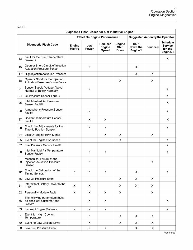
3. The “DIAGNOSTIC” lamp will flash in orderto indicate a two-digit code. The sequenceof flashes represents the system diagnosticmessage. Each digit of the two-digit code isdetermined by counting the number of flashes.The lamp flashes at a rate of two times persecond. The lamp will pause for one secondbetween digits. The lamp will pause for twoseconds between codes.
Table 8 indicates the potential effect on the engineperformance with active flash codes. Table 8 alsoforms a list of Electronic diagnostic codes anddescriptions.
35Operation Section
Engine Diagnostics
Table 8
Diagnostic Flash Codes for C-9 Industrial Engine
Effect On Engine Performance Suggested Action by the Operator
Diagnostic Flash Code EngineMisfire
LowPower
ReducedEngineSpeed
EngineShutDown
Shutdown theEngine(1)
Service(2)
ScheduleServicefor the
Engine.(3)
13 Fault for the Fuel TemperatureSensor(4) X
15 Open or Short Circuit of InjectionActuation Pressure Sensor X X
17 High Injection Actuation Pressure X X
18 Open or Short for the InjectionActuation Pressure Control Valve X X
21 Sensor Supply Voltage AboveNormal or Below Normal(4) X X
24 Oil Pressure Sensor Fault (4) X
25 Inlet Manifold Air PressureSensor Fault(5) X
26 Atmospheric Pressure SensorFault(4) X X
27 Coolant Temperature SensorFault(4) X X X
28 Check the Adjustments for theThrottle Position Sensor. X X X
34 Loss Of Engine RPM Signal X X X
35 Event for Engine Overspeed X X
37 Fuel Pressure Sensor Fault(4) X
38 Inlet Manifold Air TemperatureSensor Fault(4) X X X
39Mechanical Failure of theInjection Actuation PressureSensor
X X
42 Check the Calibration of theTiming Sensor. X X X X X
46 Low Oil Pressure Event X X X
51 Intermittent Battery Power to theECM X X X X X
52 Personality Module Fault X X X X X
56The following parameters mustbe checked: Customer andSystem
X X X
59 Incorrect Engine Software X X X X
61 Event for High CoolantTemperature X X X X
62 Event for Low Coolant Level X X X X
63 Low Fuel Pressure Event X X X X
(continued)

36Operation SectionEngine Diagnostics
(Table 8, contd)
Diagnostic Flash Codes for C-9 Industrial Engine
Effect On Engine Performance Suggested Action by the Operator
Diagnostic Flash Code EngineMisfire
LowPower
ReducedEngineSpeed
EngineShutDown
Shutdown theEngine(1)
Service(2)
ScheduleServicefor the
Engine.(3)
64 Even for High Inlet Manifold AirTemperature X X X
65 Event for High Fuel Temperature X X X
72 Fault of Cylinder 1 or Cylinder 2 X X X
73 Fault of Cylinder 3 or Cylinder 4 X X X
74 Fault of Cylinder 5 or Cylinder 6 X X X
(1) Shut down the Engine: Operate the engine cautiously. Get immediate service. Severe engine damage may result.(2) The operator should go to the nearest location for service.(3) The operator should investigate the problem at a convenient time.(4) The Diagnostic Flash Codes reduce the effectiveness of the Engine Monitoring feature.(5) These Diagnostic Flash Codes may affect the system only under specific environmental conditions such as engine start-up at cold
temperatures, etc.
i01463504
Fault LoggingSMCS Code: 1000; 1900; 1901; 1902
The system provides the capability of FaultLogging. When the Electronic Control Module (ECM)generates an active diagnostic code, the code willbe logged in the memory of the ECM. The codesthat have been logged in the memory of the ECMcan be retrieved with Caterpillar electronic servicetools. The codes that have been logged can becleared with Caterpillar electronic service tools.The codes that have been logged in the memoryof the ECM will be automatically cleared from thememory after 100 hours. The following faults cannot be cleared from the memory of the ECM withoutusing a factory password: overspeed, low engineoil pressure, and high engine coolant temperature.

37Operation Section
Engine Diagnostics
i01563981
Engine Operation with ActiveDiagnostic CodesSMCS Code: 1000; 1900; 1901; 1902
If the diagnostic lamp starts to flash codes duringnormal engine operation, the system has identifieda situation that is not within the specification. UseCaterpillar electronic service tools to check theactive diagnostic codes.
Note: If the customer has selected “DERATE” and ifthere is a low oil pressure condition, the ElectronicControl Module (ECM) will limit the engine poweruntil the problem is corrected. If the oil pressureis within the normal range, the engine may beoperated at the rated speed and load. However,maintenance should be performed as soon aspossible. Refer to Operation and MaintenanceManual, “Diagnostic Flash Code Retrieval” for moreinformation on flash codes.
The active diagnostic code should be investigated.The cause of the problem should be correctedas soon as possible. If the cause of the activediagnostic code is repaired and there is only oneactive diagnostic code, the diagnostic lamp willturn off.
Operation of the engine and performance of theengine can be limited as a result of the activediagnostic code that is generated. Accelerationrates may be significantly slower. Refer to theOperation and Maintenance Manual for moreinformation on the relationship between these activediagnostic codes and engine performance.
i01456915
Engine Operation withIntermittent Diagnostic CodesSMCS Code: 1000; 1900; 1901; 1902
If the diagnostic lamp starts to flash codes duringnormal engine operation and the diagnostic lampshuts off, an intermittent fault may have occurred. Ifa fault has occurred, the fault will be logged into thememory of the Electronic Control Module (ECM).
In most cases, it is not necessary to stop theengine because of an intermittent code. However,the operator should retrieve the logged fault codesand the operator should reference the appropriateinformation in order to identify the nature of theevent. The operator should log any observation thatcould have caused the lamp to light.
• Low power
• Limits of the engine speed
• Excessive smoke, etc
This information can be useful to help troubleshootthe situation. The information can also be used forfuture reference. For more information on diagnosticcodes, refer to the Troubleshooting Guide for thisengine.

38Operation SectionEngine Diagnostics
i00160113
Customer SpecifiedParametersSMCS Code: 1000; 1900; 1901; 1902
Customer specified parameters that will enhancethe fuel efficiency and the operator’s conveniencecan be programmed into the Electronic ControlModule (ECM). Some parameters may affect engineoperation. This may lead to complaints from theoperator about power or about performance.The following engine related parameters may beprogrammed by the customer by using Caterpillarelectronic service tools in order to influence theoperation of the engine:
• Customer Passwords
• Power Rating (hp at rpm)
• Rating Selection (A-E)
• Air/Fuel Ratio
• PTO Ramp Rate
• Engine Parameters: Low Idle, High Idle, TopEngine Limit, Torque Limit, and IntermediateSpeed
• Engine Monitoring Mode
• Equipment ID
• Maintenance Indicator
• Auxiliary Pressure
• Auxiliary Temperature
• Parameter Lock Out
The customer specified parameters can bechanged as often as needed. Password protectionis provided so that the customer can change theparameters. The customer can authorize someoneelse to change the parameters. Ensure that a recordof the parameters is kept in the Operation andMaintenance Manual. For detailed instructions onprogramming the engine for optimum performanceand for optimum fuel economy, consult yourCaterpillar dealer.

39Operation Section
Engine Starting
Engine Starting
i01486758
Before Starting EngineSMCS Code: 1000; 1400; 1450
Perform the required daily maintenance andother periodic maintenance before the engine isstarted. Inspect the engine compartment. Thisinspection can help prevent major repairs at alater date. Refer to the Operation and MaintenanceManual, “Maintenance Interval Schedule” for moreinformation.
• For the maximum service life of the engine,make a thorough inspection before the engineis started. Look for the following items: oil leaks,coolant leaks, loose bolts, and trash buildup.Remove trash buildup and arrange for repairs,as needed.
• Inspect the cooling system hoses for cracks andfor loose clamps.
• Inspect the alternator and accessory drive beltsfor cracks, breaks, and other damage.
• Inspect the wiring for loose connections and forworn wires or frayed wires.
• Check the fuel supply. Drain water from the waterseparator (if equipped). Open the fuel supplyvalve.
NOTICEAll valves in the fuel return line must be open beforeand during engine operation to help prevent high fuelpressure. High fuel pressure may cause filter housingfailure or other damage.
If the engine has not been started for severalweeks, fuel may have drained from the fuel system.Air may have entered the filter housing. Also, whenfuel filters have been changed, some air pocketswill be trapped in the engine. In these instances,prime the fuel system. Refer to the Operation andMaintenance Manual, “Fuel System - Prime” formore information on priming the fuel system.
Engine exhaust contains products of combustionwhich may be harmful to your health. Always startand operate the engine in a well ventilated areaand, if in an enclosed area, vent the exhaust to theoutside.
• Do not start the engine or move any of thecontrols if there is a “DO NOT OPERATE” warningtag or similar warning tag attached to the startswitch or to the controls.
• Ensure that the areas around the rotating partsare clear.
• All of the guards must be put in place. Check fordamaged guards or for missing guards. Repairany damaged guards. Replace damaged guardsand/or missing guards.
• Disconnect any battery chargers that are notprotected against the high current drain thatis created when the electric starting motor (ifequipped) is engaged. Check electrical cablesand check the battery for poor connections andfor corrosion.
• Reset all of the shutoffs or alarm components.
• Check the engine lubrication oil level. Maintainthe oil level between the “ADD” mark and the“FULL” mark on the oil level gauge.
• Check the coolant level. Observe the coolantlevel in the coolant recovery tank (if equipped).Maintain the coolant level to the “FULL” mark onthe coolant recovery tank.
• If the engine is not equipped with a coolantrecovery tank maintain the coolant level within13 mm (0.5 inch) of the bottom of the filler pipe.If the engine is equipped with a sight glass,maintain the coolant level in the sight glass.
• Observe the air cleaner service indicator (ifequipped). Service the air cleaner when theyellow diaphragm enters the red zone, or whenthe red piston locks in the visible position.
• Ensure that any driven equipment has beendisengaged. Minimize electrical loads or removeany electrical loads.

40Operation SectionEngine Starting
i01512354
Starting the EngineSMCS Code: 1000; 1450
Engine exhaust contains products of combustionwhich may be harmful to your health. Always startand operate the engine in a well ventilated areaand, if in an enclosed area, vent the exhaust to theoutside.
Initial Inspection
Perform the required daily maintenance and otherperiodic maintenance before you start the engine.Inspect the engine compartment. This inspectioncan help prevent major repairs at a later date.Refer to the Operation and Maintenance Manual,“Walk-Around Inspection” topic (MaintenanceSection) for more information.
• For the maximum service life of the engine, makea thorough inspection before you start the engine.Look for the following items: oil leaks, coolantleaks, loose bolts, and trash buildup. Removetrash buildup and arrange for repairs, as needed.
• Inspect the cooling system hoses for cracks andfor loose clamps.
• Inspect the alternator and accessory drive beltsfor cracks, breaks, and other damage.
• Inspect the wiring for loose connections and forworn wires or frayed wires.
• Check the fuel supply. Drain water from the waterseparator (if equipped). Open the fuel supplyvalve.
NOTICEAll valves in the fuel return line must be open beforeand during engine operation to help prevent high fuelpressure. High fuel pressure may cause filter housingfailure or other damage.
• Do not start the engine or do not move any of thecontrols if there is a “DO NOT OPERATE” warningtag or similar warning tag attached to the startswitch or to the controls.
• Ensure that the areas around the rotating partsare clear.
• All of the guards must be put in place. Check fordamaged guards or for missing guards. Repairany damaged guards. Replace damaged guardsand/or missing guards.
• Disconnect any battery chargers that are notprotected against the high current drain thatis created when the electric starting motor (ifequipped) is engaged. Check electrical cablesand check the battery for poor connections andfor corrosion.
• Reset all of the shutoffs or alarm components.
• Check the engine lubrication oil level. Maintainthe oil level between the “ADD” mark and the“FULL” mark on the oil level gauge.
• Check the coolant level. Observe the coolantlevel in the coolant recovery tank (if equipped).Maintain the coolant level to the “FULL” mark onthe coolant recovery tank.
• If the engine is not equipped with a coolantrecovery tank maintain the coolant level within13 mm (.5 inch) of the bottom of the filler pipe.If the engine is equipped with a sight glass,maintain the coolant level in the sight glass.
• Observe the air cleaner service indicator (ifequipped). Service the air cleaner when theyellow diaphragm enters the red zone, or whenthe red piston locks in the visible position.
• Ensure that any driven equipment has beendisengaged. Remove any electrical loads.
Cold Weather Starting
Starting the engine and operation in cold weather isdependent on the type of fuel that is used, the oilviscosity, and other optional starting aids. For moreinformation, refer to the Operation and MaintenanceManual, “Cold Weather Operation” topic (OperationSection).
Air Inlet Heater
DO NOT USE ETHER (starting fluids) unlessspecifically instructed to do so. If the engine isequipped with an Air Inlet Heater (electrically orfuel ignited manifold heater), DO NOT use ether(starting fluids) at any time. The use could resultin engine damage and/or personal injury.
Note: There will be an indicator lamp on the controlpanel that is marked “AIR INLET HEATER”.
41Operation Section
Engine Starting
For detailed information on the operation of the AirInlet Heater, refer to Troubleshooting Manual, “AirInlet Heater Circuit - Test”.
Refer to the Owner’s Manual of the OEM for yourtype of controls. Use the following procedure tostart the engine.
1. Place the transmission in NEUTRAL. Disengagethe flywheel clutch in order to allow the engineto start faster. This also reduces the draining ofthe battery.
2. Turn the ignition switch to the ON position.
The “WARNING and DIAGNOSTIC” lamp (ifequipped) will flash while the engine is cranking.The lamp should turn off after proper engineoil pressure is achieved. If the lamp fails toflash, notify your authorized Caterpillar dealer.If the lamp continues to flash, the ElectronicControl Module (ECM) has detected a problemin the system. For more information, refer to theOperation and Maintenance Manual, “DiagnosticFlash Code Retrival” (Operation Section).
NOTICEDo not engage the starting motor when flywheel isturning. Do not start the engine under load.
If the engine fails to start within 30 seconds, releasethe starter switch or button and wait two minutes toallow the starting motor to cool before attempting tostart the engine again.
3. Push the start button or turn the ignition switch tothe START position in order to crank the engine.
Do not push down or hold the throttle downwhile the engine is cranked. The system willautomatically provide the correct amount of fuelthat is needed to start the engine.
4. If the engine fails to start within 30 seconds,release the start button, or the ignition switch.Wait for two minutes in order to allow the startingmotor to cool before attempting to start theengine again.
Note: The “WARNING and DIAGNOSTIC” lamps (ifequipped) may come on after the engine is started.If this occurs, the ECM has detected a problemwith the system. For more information, refer to theOperation and Maintenance Manual, “DiagnosticFlash Code Retrival” (Operation Section) .
NOTICEOil pressure should rise within 15 seconds after theengine starts. Do not increase engine rpm until the oilpressure gauge indicates normal. If oil pressure is notindicated on the gauge within 15 seconds, DO NOToperate the engine. STOP the engine, investigate andcorrect the cause.
5. Allow the engine to idle for approximatelythree minutes. Idle the engine until the watertemperature gauge has begun to rise. Check allgauges during the warm-up period.
Note: Oil pressures and fuel pressures should be inthe normal range on the instrument panel. Enginesthat are equipped with “WARNING” lamps do nothave an operating range. The “WARNING andDIAGNOSTIC” lamp (if equipped) will flash whilethe engine is cranking. The lamp should turn offafter proper engine oil pressure or fuel pressureis achieved. Do not apply a load to the engine orincrease engine rpm until the oil pressure gaugeindicates at least normal pressure. Inspect theengine for leaks and/or unusual noises.
After the engine has started, the air inlet heater maycontinue to operate in a “Continuous” mode and/orin an “Intermittent” mode. The air inlet heater willturn OFF when the sum of the coolant temperatureand the air inlet temperature exceeds 35 �C or 127�F.
If the engine is operated with a low load, the enginewill reach normal operating temperature sooner thanidling the engine with no load. When the engine isidled in cold weather, increase the engine rpm toapproximately 1000 to 1200 rpm. This will warmup the engine more quickly. Do not exceed therecommended rpm in order to increase the speedof the warm-up. Limit unnecessary idle time to tenminutes.
Ether Injection System
Personal injury or property damage can resultfrom alcohol or starting fluids.
Alcohol or starting fluids are highly flammable andtoxic and if improperly stored could result in injuryor property damage.

42Operation SectionEngine Starting
DO NOT USE ETHER (starting fluids) unlessspecifically instructed to do so. If the engine isequipped with an Air Inlet Heater (electrically orfuel ignited manifold heater), DO NOT use ether(starting fluids) at any time. The use could resultin engine damage and/or personal injury.
NOTICEThe optional automatic ether injection system is theonly starting fluid system that is recommended. Ex-cessive starting fluid can cause piston and ring dam-age. Use starting fluid for cold starting purposes only.
Startability will be improved at temperatures below0 �C (32 �F) by the use of a continuous flow injectionsystem and/or a jacket water heater. This will helpalleviate white smoke and misfire during start-upin cold weather. Consult your Caterpillar dealerfor other means of improving startability in coldtemperatures.
The Continuous Flow Ether is an optional etherstarting aid that is available for use with the engine.The system injects ether into the air inlet manifoldafter the air inlet heater. Extensive damage to theengine could occur if ether is directed at the airinlet heater during activation.
Continuous Flow Ether Control has two modes, theManual Mode and the Automatic Mode.
Manual Mode:
In the manual mode, as the ether switch isdepressed there is a predetermined amount ofether that is injected. The manual mode is disabled,if the engine speed is more than 200 rpm above thelow idle, if the ambient air temperature is above 0�
C (32� F), or if the coolant temperature is above0� C 32� F.
If the engine is equipped with the ether injectionsystem, perform the following procedure for themanual mode:
1. Crank the engine.
2. Depress the ether switch.
3. Hold the ether switch for three seconds.
4. Release the ether switch.
Automatic Mode:
When the ether switch is placed in the automaticmode, the ether injection system operatesautomatically, when the engine is cranking. Theautomatic mode is enabled if the engine has beenidling for less than 10 seconds, if the engine speedis less than 200 rpm above low idle, if the ambientair temperature is below 0� C (32� F), and if thecoolant temperature is below 0� (32� F).
Additional injections may be necessary in orderto start the engine. Additional injections may benecessary in order to achieve the low idle speed.For additional information on the Ether InjectionSystem refer to Troubleshooting Manual, “Air InletHeater Circuit - Test”.
Starting Problems
An occasional starting problem may be caused byone of the following items:
• Low battery charge
• Lack of fuel
• Problem with the wiring harness
If the engine fuel system has been run dry, fill thefuel tank and prime the fuel system. Refer to theOperation and Maintenance Manual, “Fuel System -Prime” topic (Maintenance Section).
If the other problems are suspected, perform theappropriate procedure in order to start the engine.
Problems with the Wiring Harness
g00772964Illustration 27
(1) ECM Connector J2/P2(2) ECM Connector J1/P1

43Operation Section
Engine Starting
Locate the ECM. Two harness connectors areattached to the ECM. One connector is ECMJ2/P2 (1) and the other connector is ECM J1/P1.Check the connectors in order to ensure that theconnectors are secure. Lightly pull each of the wiresin the chassis harness.
1. Pull each wire with approximately 4.5 kg (10 lb)of force. The wire should remain in the connector.
2. If a wire is loose, push the wire back into theconnector. Pull the wire again in order to ensurethat the wire is secure.
3. Start the engine. If the engine does not start,consult the nearest Caterpillar dealer forassistance.
i01037941
Starting with Jump StartCablesSMCS Code: 1000; 1401; 1402; 1900
Improper jump start cable connections can causean explosion resulting in personal injury.
Prevent sparks near the batteries. Sparks couldcause vapors to explode. Do not allow jump startcable ends to contact each other or the engine.
If the installation is not equipped with a backupbattery system, it may be necessary to start theengine from an external electrical source.
First, determine the reason that it is necessary tostart with power from an external source. Refer toSpecial Instruction, SEHS7768, “Use of the 6V-2150Starting/Charging Analyzer”.
Many batteries which are considered unusable arestill rechargeable. After jump starting, the alternatormay not be able to fully recharge batteries thatare severely discharged. The batteries must becharged to the proper voltage with a batterycharger. For information on testing and charging,refer to the Special Instruction, SEHS7633, “BatteryTest Procedure”.
NOTICEUsing a battery source with the same voltage as theelectric starting motor. Use ONLY equal voltage forjump starting. The use of higher voltage will damagethe electrical system.
Do not reverse the battery cables. The alternator canbe damaged. Attach ground cable last and removefirst.
When using an external electrical source to start theengine, turn the engine control switch to the “OFF” po-sition. Turn all electrical accessories OFF before at-taching the jump start cables.
Ensure that the main power switch is in the OFF posi-tion before attaching the jump start cables to the en-gine being started.
1. Turn the start switch on the stalled engine to theOFF position. Turn off all accessories.
2. Connect one positive end of the jump start cableto the positive cable terminal of the dischargedbattery. Connect the other positive end of thejump start cable to the positive cable terminalof the electrical source.
3. Connect one negative end of the jump start cableto the negative cable terminal of the electricalsource. Connect the other negative end of thejump start cable to the engine block or to thechassis ground. This procedure helps to preventpotential sparks from igniting combustible gasesthat are produced by some batteries.
4. Charge the batteries. The engine will notcontinue to run after starting if the batteries havenot been charged.
5. Start the engine.
6. Immediately after the stalled engine is started,disconnect the jump start cables in reverse order.
Refer to the Electrical Schematic for your engine.Consult your Caterpillar dealer for more information.
44Operation SectionEngine Starting
i01646248
After Starting EngineSMCS Code: 1000
Note: In temperatures from 0 to 60�C (32 to 140�F),the warm-up time is approximately three minutes. Intemperatures below 0�C (32�F), additional warm-uptime may be required.
Note: Ensure that the self test for the monitoringsystem (if equipped) is completed before operatingthe engine under load.
When the engine idles during warm-up, observethe following conditions:
• Check for any fluid or for any air leaks at idle rpmand at one-half full rpm (no load on the engine)before operating the engine under load. This isnot possible in some applications.
• Operate the engine at low idle until all systemsachieve operating temperatures. Check allgauges during the warm-up period.
Note: Gauge readings should be observed and thedata should be recorded frequently while the engineis operating. Comparing the data over time willhelp to determine normal readings for each gauge.Comparing data over time will also help detectabnormal operating developments. Significantchanges in the readings should be investigated.

45Operation SectionEngine Operation
Engine Operation
i00718869
Engine OperationSMCS Code: 1000
Proper operation and maintenance are key factorsin obtaining the maximum life and economy ofthe engine. If the directions in the Operation andMaintenance Manual are followed, costs canbe minimized and engine service life can bemaximized.
The time that is needed for the engine to reachnormal operating temperature can be less than thetime needed for a walk-around inspection of theengine.
After the engine is started and after the enginereaches normal operating temperature, the enginecan be operated at the rated rpm. The engine willreach normal operating temperature faster whenthe engine is at rated speed. The engine will reachnormal operating temperature faster when theengine is at low power demand. This procedure ismore effective than idling the engine at no load.The engine should reach operating temperature ina few minutes.
Gauge readings should be observed and the datashould be recorded frequently while the engine isoperating. Comparing the data over time will helpto determine normal readings for each gauge.Comparing data over time will also help detectabnormal operating developments. Significantchanges in the readings should be investigated.
i01646335
Engaging the DrivenEquipmentSMCS Code: 1000
1. Operate the engine at one-half of the rated rpm,when possible.
2. Engage the driven equipment without a load onthe equipment, when possible.
Interrupted starts put excessive stress on thedrive train. Interrupted starts also waste fuel. Toget the driven equipment in motion, engage theclutch smoothly with no load on the equipment.This method should produce a start that issmooth and easy. The engine rpm should notincrease and the clutch should not slip.
3. Ensure that the ranges of the gauges are normalwhen the engine is operating at one-half ofthe rated rpm. Ensure that all gauges operateproperly.
4. Increase the engine rpm to the rated rpm. Alwaysincrease the engine rpm to the rated rpm beforethe load is applied.
5. Apply the load. Begin operating the engine atlow load. Check the gauges and equipment forproper operation. After normal oil pressure isreached and the temperature gauge begins tomove, the engine may be operated at full load.Check the gauges and equipment frequentlywhen the engine is operated under load.
Extended operation at low idle or at reducedload may cause increased oil consumption andcarbon buildup in the cylinders. This carbonbuildup results in a loss of power and/or poorperformance.

46Operation SectionEngine Stopping
Engine Stopping
i01428739
Stopping the EngineSMCS Code: 1000; 7000
NOTICEStopping the engine immediately after it has beenworking under load can result in overheating and ac-celerated wear of the engine components.
If the engine has been operating at high rpm and/orhigh loads, run at low idle for at least three minutesto reduce and stabilize internal engine temperaturebefore stopping the engine.
Avoiding hot engine shutdowns will maximize tur-bocharger shaft and bearing life.
Prior to stopping an engine that is being operatedat low loads, operate the engine at low idle for 30seconds before stopping. If the engine has beenoperating at highway speeds and/or at high loads,operate the engine at low idle for at least threeminutes. This procedure will cause the internalengine temperature to be reduced and stabilized.
Ensure that the engine stopping procedure isunderstood. Stop the engine according to theshutoff system on the engine or refer to theinstructions that are provided by the OEM.
• To stop the engine, turn the ignition key switch tothe OFF position.
i01057253
Emergency StoppingSMCS Code: 1000; 7418
NOTICEEmergency shutoff controls are for EMERGENCY useONLY. DO NOT use emergency shutoff devices orcontrols for normal stopping procedure.
Ensure that any components for the external systemthat support the engine operation are secured afterthe engine is stopped.
Emergency Stop Button
g00104303Illustration 28
Typical emergency stop button
The emergency stop button is in the OUT positionfor normal engine operation. Push the emergencystop button. The engine will not start when thebutton is locked. Turn the button clockwise in orderto reset.

47Operation Section
Engine Stopping
i01646416
Manual Stop ProcedureSMCS Code: 1000
Note: Individual applications will have differentcontrol systems. Ensure that the shutoff proceduresare understood. Use the following generalguidelines in order to stop the engine.
1. Remove the load, when possible. Reduce theengine speed (rpm) to low idle.
2. Increase the engine speed (rpm) to no morethan one-half of the rated rpm. Perform thisprocedure for three to five minutes in order tocool the engine. Reduce the engine speed (rpm)to low idle.
3. After the cool down period, turn the key switchto the OFF position.
i01465494
After Stopping EngineSMCS Code: 1000
Note: Before you check the engine oil, do notoperate the engine for at least 10 minutes in orderto allow the engine oil to return to the oil pan.
• Check the crankcase oil level. Maintain the oillevel between the “ADD” mark and the “FULL”mark on the oil level gauge.
• If necessary, perform minor adjustments. Repairany leaks and tighten any loose bolts.
• Note the service hour meter reading. Performthe maintenance that is in the Operation andMaintenance Manual, “Maintenance IntervalSchedule”.
• Fill the fuel tank in order to help preventaccumulation of moisture in the fuel. Do notoverfill the fuel tank.
NOTICEOnly use antifreeze/coolant mixtures recommended inthe Coolant Specifications that are in the Operationand Maintenance Manual. Failure to do so can causeengine damage.
• Allow the engine to cool. Check the coolant level.
• If freezing temperatures are expected, checkthe coolant for proper antifreeze protection. Thecooling system must be protected against freezingto the lowest expected outside temperature. Addthe proper coolant/water mixture, if necessary.
• Perform all required periodic maintenance on alldriven equipment. This maintenance is outlined inthe instructions from the OEM.

48Operation SectionCold Weather Operation
Cold Weather Operation
i01457051
Radiator RestrictionsSMCS Code: 1353; 1396
Caterpillar discourages the use of airflow restrictiondevices that are mounted in front of radiators. Airflowrestriction can cause the following conditions:
• High exhaust temperatures
• Power loss
• Excessive fan usage
• Reduction in fuel economy
If an airflow restriction device must be used, thedevice should have a permanent opening directlyin line with the fan hub. The device must have aminimum opening dimension of at least 770 cm2
(120 in2).
A centered opening that is directly in line withthe fan hub is specified in order to prevent aninterrupted airflow on the fan blades. Interruptedairflow on the fan blades could cause a fan failure.
Caterpillar recommends a warning device for theinlet manifold temperature and/or the installation ofan inlet air temperature gauge. The warning devicefor the inlet manifold temperature should be set at75 �C (167 �F). The inlet manifold air temperatureshould not exceed 75 �C (167 �F). Temperaturesthat exceed this limit can cause power loss andpotential engine damage.
i01190421
Fuel and the Effect from ColdWeatherSMCS Code: 1000; 1250
The following fuels are the grades that are availablefor Caterpillar engines:
• No. 1
• No. 2
• Blend of No. 1 and No. 2
No. 2 diesel fuel is the most commonly used fuel.Either No. 1 diesel fuel or a blend of No. 1 and No.2 is best suited for cold weather operation.
Quantities of No. 1 diesel fuel are limited. No.1 diesel fuels are usually available during themonths of the winter in the colder climates. Duringcold weather operation, if No. 1 diesel fuel is notavailable, use No. 2 diesel fuel, if necessary.
There are three major differences between No. 1and No. 2 diesel fuel. No. 1 diesel fuel has thefollowing properties:
• Lower cloud point
• Lower pour point
• Lower rating of kJ (BTU) per unit volume of fuel
When No. 1 diesel fuel is used, a decrease inpower and in fuel efficiency may be noticed. Otheroperating effects should not be experienced.
The cloud point is the temperature when a cloudof wax crystals begins to form in the fuel. Thesecrystals can cause the fuel filters to plug. Thepour point is the temperature when diesel fuel willthicken. The diesel fuel becomes more resistant toflow through fuel pumps and through fuel lines.
Be aware of these values when diesel fuel ispurchased. Anticipate the average ambienttemperature within the area that the engine will beoperated. Engines that are fueled in one climatemay not operate well if the engines are movedto another climate. Problems can result due tochanges in temperature.
Before troubleshooting for low power or for poorperformance in the winter, check the type of fuelthat is being used.
When No. 2 diesel fuel is used the followingcomponents provide a means of minimizingproblems in cold weather:
• Starting aids
• Engine oil pan heaters
• Engine coolant heaters
• Fuel heaters
• Fuel line insulation
For more information on cold weather operation, seeOperation and Maintenance Manual, SEBU5898,“Cold Weather Recommendations”.

49Operation Section
Cold Weather Operation
i01505157
Fuel Related Components inCold WeatherSMCS Code: 1000; 1250
Fuel Tanks
Condensation can form in partially filled fuel tanks.Top off the fuel tanks after operating the engine.
Fuel tanks should contain some provision fordraining water and sediment from the bottom of thetanks. Some fuel tanks use supply pipes that allowwater and sediment to settle below the end of thefuel supply pipe.
Some fuel tanks use supply lines that take fueldirectly from the bottom of the tank. If the engine isequipped with this system, regular maintenance ofthe fuel system filter is important.
Drain the water and sediment from any fuel storagetank at the following intervals:
• Weekly
• Oil changes
• Refueling of the fuel tank
This will help prevent water and/or sediment frombeing pumped from the fuel storage tank and intothe engine fuel tank.
Fuel Filters
NOTICEDo not fill the fuel filters with fuel before installing them.The fuel would not be filtered and could be contami-nated. Contaminated fuel will cause accelerated wearto fuel system parts.
NOTICEIn order to maximize fuel system life and prevent pre-mature wear out from abrasive particles in the fuel,a two micron absolute high efficiency fuel filter is re-quired for all Caterpillar Hydraulic Electronic Unit In-jectors. Caterpillar High Efficiency Fuel Filters meetthese requirements. Consult your Caterpillar dealer forthe proper part numbers.
These engines are equipped with a primaryfilter/water separator. The primary filter/waterseparator must use a 10 micron filter to a 15 micronfilter. The filters are becoming more critical as fuelinjection pressures increase to 209 MPa (30000 psi)and higher psi. For more information on priming thefuel system, see the Operation and MaintenanceManual, “Fuel System - Prime” topic (MaintenanceSection).
Fuel Heaters
Fuel heaters help to prevent fuel filters fromplugging in cold weather due to waxing. A fuelheater should be installed in order for the fuel to beheated before the fuel enters the primary fuel filter.
Select a fuel heater that is mechanically simple,yet adequate for the application. The fuel heatershould also help to prevent overheating of the fuel.High fuel temperatures reduce engine performanceand the availability of engine power. Choose a fuelheater with a large heating surface. The fuel heatershould be practical in size. Small heaters can betoo hot due to the limited surface area.
Disconnect the fuel heater in warm weather.
Note: Fuel heaters that are controlled by the watertemperature regulator or self-regulating fuel heatersshould be used with this engine. Fuel heatersthat are not controlled by the water temperatureregulator can heat the fuel in excess of 65� C(149� F). A loss of engine power can occur if thefuel supply temperature exceeds 37� C (100� F).
Note: Heat exchanger type fuel heaters should havea bypass provision in order to prevent overheatingof the fuel in warm weather operation.
For further information on fuel heaters, consult yourCaterpillar dealer.
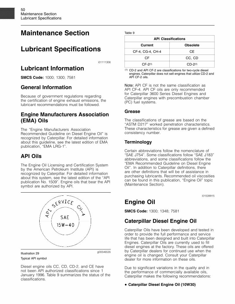
50Maintenance SectionLubricant Specifications
Maintenance Section
Lubricant Specifications
i01111306
Lubricant InformationSMCS Code: 1000; 1300; 7581
General Information
Because of government regulations regardingthe certification of engine exhaust emissions, thelubricant recommendations must be followed.
Engine Manufacturers Association(EMA) Oils
The “Engine Manufacturers AssociationRecommended Guideline on Diesel Engine Oil” isrecognized by Caterpillar. For detailed informationabout this guideline, see the latest edition of EMApublication, “EMA LRG-1”.
API Oils
The Engine Oil Licensing and Certification Systemby the American Petroleum Institute (API) isrecognized by Caterpillar. For detailed informationabout this system, see the latest edition of the “APIpublication No. 1509”. Engine oils that bear the APIsymbol are authorized by API.
g00546535Illustration 29
Typical API symbol
Diesel engine oils CC, CD, CD-2, and CE havenot been API authorized classifications since 1January 1996. Table 9 summarizes the status of theclassifications.
Table 9
API Classifications
Current Obsolete
CF-4, CG-4, CH-4 CE
CF CC, CD
CF-2(1) CD-2(1)
(1) CD-2 and API CF-2 are classifications for two-cycle dieselengines. Caterpillar does not sell engines that utilize CD-2 andAPI CF-2 oils.
Note: API CF is not the same classification asAPI CF-4. API CF oils are only recommendedfor Caterpillar 3600 Series Diesel Engines andCaterpillar engines with precombustion chamber(PC) fuel systems.
Grease
The classifications of grease are based on the“ASTM D217” worked penetration characteristics.These characteristics for grease are given a definedconsistency number.
Terminology
Certain abbreviations follow the nomenclature of“SAE J754”. Some classifications follow “SAE J183”abbreviations, and some classifications follow the“EMA Recommended Guideline on Diesel EngineOil”. In addition to Caterpillar definitions, thereare other definitions that will be of assistance inpurchasing lubricants. Recommended oil viscositiescan be found in this publication, “Engine Oil” topic(Maintenance Section).
i01539915
Engine OilSMCS Code: 1300; 1348; 7581
Caterpillar Diesel Engine Oil
Caterpillar Oils have been developed and tested inorder to provide the full performance and servicelife that has been designed and built into CaterpillarEngines. Caterpillar Oils are currently used to filldiesel engines at the factory. These oils are offeredby Caterpillar dealers for continued use when theengine oil is changed. Consult your Caterpillardealer for more information on these oils.
Due to significant variations in the quality and inthe performance of commercially available oils,Caterpillar makes the following recommendations:
• Caterpillar Diesel Engine Oil (10W30)

51Maintenance Section
Lubricant Specifications
• Caterpillar Diesel Engine Oil (15W40)
Caterpillar multigrade Diesel Engine Oil isformulated with the correct amounts of detergents,dispersants, and alkalinity in order to providesuperior performance in Caterpillar Diesel Engines.
Caterpillar multigrade Diesel Engine Oil is availablein two viscosity grades (10W30 and 15W40). Fordirect injection engines, see Table 10 in orderto choose the correct viscosity grade for theambient temperature. Multigrade oils provide thecorrect viscosity for a broad range of operatingtemperatures.
Multigrade oils are effective in maintaining low oilconsumption and low levels of piston deposits.
Caterpillar multigrade Diesel Engine Oil can beused in other diesel engines and in gasolineengines. See the engine manufacturer’s guide forthe recommended specifications. Compare thespecifications to the specifications of Caterpillarmultigrade Diesel Engine Oil. The current industrystandards for Caterpillar Diesel Engine Oil are listedon the product label and on the data sheets for theproduct.
Consult your Caterpillar dealer for part numbersand for available sizes of containers.
Commercial Oils
The performance of commercial diesel engineoils is based on American Petroleum Institute(API) classifications. These API classifications aredeveloped in order to provide commercial lubricantsfor a broad range of diesel engines that operate atvarious conditions.
If Caterpillar multigrade Diesel Engine Oil is notused, only use commercial oils that meet thefollowing classifications:
• EMA LRG-1 multigrade oil (preferred oil)
• API CH-4 multigrade oil (preferred oil)
• API CG-4 multigrade oil (preferred oil)
• API CF-4 multigrade oil (acceptable oil)
In order to make the proper choice of a commercialoil, refer to the following explanations:
EMA LRG-1 – The Engine ManufacturersAssociation (EMA) has developed lubricantrecommendations as an alternative to the API oilclassification system. LRG-1 is a RecommendedGuideline that defines a level of oil performancefor these types of diesel engines: high speed, fourstroke cycle, heavy-duty, and light duty. LRG-1oils may be used in Caterpillar engines when thefollowing oils are recommended: API CH-4, APICG-4, and API CF-4. LRG-1 oils are intended toprovide superior performance in comparison to APICG-4 and API CF-4.
LRG-1 oils will meet the needs of high performanceCaterpillar diesel engines that are operating inmany applications. The tests and the test limits thatare used to define LRG-1 are similar to the newAPI CH-4 classification. Therefore, these oils willalso meet the requirements of the low emissionsdiesel engines. LRG-1 oils are designed to controlthe harmful effects of soot with improved wearresistance and improved resistance to plugging ofthe oil filter. These oils will also provide superiorpiston deposit control for engines with eithertwo-piece steel pistons or aluminum pistons.
All LRG-1 oils must complete a full test programwith the base stock and with the viscosity grade ofthe finished commercial oil. The use of “API BaseOil Interchange Guidelines” are not appropriate forLRG-1 oils. This feature reduces the variation inperformance that can occur when base stocks arechanged in commercial oil formulations.
LRG-1 oils are recommended for use in extendedoil change interval programs that optimize oil life.These oil change interval programs are basedon oil analysis. LRG-1 oils are recommendedfor conditions that demand a premium oil. YourCaterpillar dealer has the specific guidelines foroptimizing oil change intervals.
API CH-4 – API CH-4 oils were developed inorder to meet the requirements of the new highperformance diesel engines. Also, the oil wasdesigned to meet the requirements of the lowemissions diesel engines. API CH-4 oils are alsoacceptable for use in older diesel engines and indiesel engines that use high sulfur diesel fuel. APICH-4 oils may be used in Caterpillar engines thatuse API CG-4 and API CF-4 oils. API CH-4 oils willgenerally exceed the performance of API CG-4 oilsin the following criteria: deposits on pistons, controlof oil consumption, wear of piston rings, valve trainwear, viscosity control, and corrosion.

52Maintenance SectionLubricant Specifications
Three new engine tests were developed for theAPI CH-4 oil. The first test specifically evaluatesdeposits on pistons for engines with the two-piecesteel piston. This test (piston deposit) also measuresthe control of oil consumption. A second test isconducted with moderate oil soot. The secondtest measures the following criteria: wear of pistonrings, wear of cylinder liners, and resistance tocorrosion. A third new test measures the followingcharacteristics with high levels of soot in the oil:wear of the valve train, resistance of the oil inplugging the oil filter, and control of sludge.
In addition to the new tests, API CH-4 oils havetougher limits for viscosity control in applicationsthat generate high soot. The oils also have improvedoxidation resistance. API CH-4 oils must pass anadditional test (piston deposit) for engines that usealuminum pistons (single piece). Oil performance isalso established for engines that operate in areaswith high sulfur diesel fuel.
All of these improvements allow the API CH-4 oilto achieve optimum oil change intervals. API CH-4oils are recommended for use in extended oilchange intervals. API CH-4 oils are recommendedfor conditions that demand a premium oil. YourCaterpillar dealer has specific guidelines foroptimizing oil change intervals.
API CG-4 – API CG-4 oils were developed primarilyfor diesel engines that use a 0.05 percent level offuel sulfur. However, API CG-4 oils can be usedwith higher sulfur fuels. The TBN of the new oildetermines the maximum fuel sulfur level for APICG-4 and API CF-4 oils. See Illustration 30.
API CG-4 oils are the first oils that are required topass industry standard tests for foam control andviscosity shear loss. API CG-4 oils must also passtests that were developed for corrosion, wear andoxidation.
API CF-4 – These oils service a wide variety ofmodern diesel engines. API CF-4 oils provide morestable oil control and reduced piston deposits incomparison to API CF and the obsolete CE and CDclassifications of oil. API CF-4 oils provide improvedsoot dispersancy in comparison to API CF andobsolete CD oils. The API CF-4 classification wasdeveloped with a 0.40 percent sulfur diesel fuel.This represents the type of diesel fuels that arecommonly available worldwide.
Note: Do not use single grade API CF oils ormultigrade API CF oils in Caterpillar Direct Injection(DI) Commercial Diesel Engines.
Some commercial oils that meet the APIclassifications may require reduced oil changeintervals. To determine the oil change interval,closely monitor the condition of the oil and perform awear metal analysis. Caterpillar’s S·O·S oil analysisprogram is the preferred method.
NOTICEFailure to follow these oil recommendations can causeshortened engine service life due to deposits and/orexcessive wear.
Total Base Number (TBN) and FuelSulfur Levels for Direct Injection(DI) Diesel Engines
The Total Base Number (TBN) for an oil depends onthe fuel sulfur level. For direct injection engines thatuse distillate fuel, the minimum TBN of the new oilmust be 10 times the fuel sulfur level. The TBN isdefined by “ASTM D2896”. The minimum TBN ofthe oil is 5 regardless of fuel sulfur level. Illustration30 demonstrates the TBN.
g00799818Illustration 30
(Y) TBN by “ASTM D2896”(X) Percentage of fuel sulfur by weight(1) TBN of new oil(2) Change the oil when the TBN deteriorates to 50 percent of
the original TBN.
Use the following guidelines for fuel sulfur levelsthat exceed 1.5 percent:
• Choose an oil with the highest TBN that meetsone of these classifications: EMA LRG-1, APICH-4, API CG-4, and API CF-4.
• Reduce the oil change interval. Base the oilchange interval on the oil analysis. Ensure thatthe oil analysis includes the condition of the oiland a wear metal analysis.

53Maintenance Section
Lubricant Specifications
Excessive piston deposits can be produced by anoil with a high TBN. These deposits can lead to aloss of control of the oil consumption and to thepolishing of the cylinder bore.
NOTICEOperating Direct Injection (DI) diesel engines with fuelsulfur levels over 1.0 percent may require shortenedoil change intervals in order to help maintain adequatewear protection.
Lubricant Viscosity Recommendationsfor Direct Injection (DI) Diesel Engines
The proper SAE viscosity grade of oil is determinedby the minimum ambient temperature duringcold engine start-up, and the maximum ambienttemperature during engine operation.
Refer to Table 10 (minimum temperature) in orderto determine the required oil viscosity for startinga cold engine.
Refer to Table 10 (maximum temperature) in orderto select the oil viscosity for engine operation at thehighest ambient temperature that is anticipated.
Generally, use the highest oil viscosity thatis available to meet the requirement for thetemperature at start-up.
Table 10
Engine Oil Viscosity
Ambient TemperatureCaterpillar DEOMultigradeEMA LRG-1
API CH-4API CG-4 and
API CF-4Viscosity Grade
Minimum Maximum
SAE 0W20 −40 �C (−40 �F) 10 �C (50 �F)
SAE 0W30 −40 �C (−40 �F) 30 �C (86 �F)
SAE 0W40 −40 �C (−40 �F) 40 �C (104 �F)
SAE 5W30 −30 �C (−22 �F) 30 �C (86 �F)
SAE 5W40 −30 �C (−22 �F) 40 �C (104 �F)
SAE 10W30 −20 �C (−4 �F) 40 �C (104 �F)
SAE 15W40 −15 �C (5 �F) 50 �C (122 �F)
i01111406
Synthetic Base Stock OilsSMCS Code: 1300; 1348; 7581
Synthetic base oils are acceptable for usein Caterpillar engines if these oils meet theperformance requirements that are specified for theengine compartment.
Synthetic base oils generally perform better thanconventional oils in the following two areas:
• Synthetic base oils have improved flow at lowtemperatures especially in arctic conditions.
• Synthetic base oils have improved oxidationstability especially at high operating temperatures.
Some synthetic base oils have performancecharacteristics that enhance the service life of theoil. However, Caterpillar does not recommend theautomatic extension of oil change intervals forany type of oil. Oil change intervals for Caterpillarengines can only be adjusted after an oil analysisprogram that contains the following tests: oilcondition and wear metal analysis (Caterpillar’sS·O·S oil analysis), trend analysis, fuel consumption,and oil consumption.
i01111412
Re-refined Base Stock OilsSMCS Code: 1300; 7581
Re-refined base stock oils are acceptable foruse in Caterpillar engines if these oils meet theperformance requirements that are specified byCaterpillar. Re-refined base stock oils can be usedexclusively in finished oil or in a combination withnew base stock oils. The US military specificationsand the specifications of other heavy equipmentmanufacturers also allow the use of re-refined basestock oils that meet the same criteria.
The process that is used to make re-refined basestock oil should adequately remove all wear metalsthat are in the used oil and all additives that arein the used oil. The process that is used to makere-refined base stock oil generally involves theprocesses of vacuum distillation and hydrotreatingthe used oil. Filtering is inadequate for theproduction of high quality re-refined base stock oilsfrom used oil.

54Maintenance SectionLubricant Specifications
i01113213
Cold Weather LubricantsSMCS Code: 1300; 1348; 7581
When an engine is started and an engine isoperated in ambient temperatures below −20 �C(−4 �F), use multigrade oils that are capable offlowing in low temperatures.
These oils have lubricant viscosity grades of SAE0W or SAE 5W.
When an engine is started and operated in ambienttemperatures below −30 �C (−22 �F), use a syntheticbase stock multigrade oil with a 0W viscosity gradeor with a 5W viscosity grade. Use an oil with a pourpoint that is lower than −50 �C (−58 �F).
The number of acceptable lubricants is limited incold weather conditions. Caterpillar recommendsthe following lubricants for use in cold weatherconditions:
First Choice – use an oil with an EMA LRG-1Recommended Guideline or use a CH-4 oil that isAPI licensed with an SAE 0W20, SAE 0W30, SAE0W40, SAE 5W30, or SAE 5W40 lubricant viscositygrade. A CG-4 oil that is API licensed with an SAE0W20, SAE 0W30, SAE 0W40, SAE 5W30, or SAE5W40 lubricant viscosity grade may also be used.A CF-4 oil that is API licensed with an SAE 0W20,SAE 0W30, SAE 0W40, SAE 5W30, or SAE 5W40lubricant viscosity grade may also be used.
Second Choice – use an oil that contains the CH-4,CG-4, or CF-4 additive package although the oilhas not been tested for the requirements of theAPI license. The oil must have an SAE 0W20,SAE 0W30, SAE 0W40, SAE 5W30, or SAE 5W40lubricant viscosity grade.
NOTICEShortened engine service life could result if secondchoice oils are used.
i01123104
Aftermarket Oil AdditivesSMCS Code: 1300; 1348; 7581
Caterpillar does not recommend the use ofaftermarket additives in oil. It is not necessary touse aftermarket additives in order to achieve theengine’s maximum service life or rated performance.Fully formulated, finished oils consist of base oilsand of commercial additive packages. Theseadditive packages are blended into the base oilsat precise percentages in order to help providefinished oils with performance characteristics thatmeet industry standards.
There are no industry standard tests that evaluatethe performance or the compatibility of aftermarketadditives in finished oil. Aftermarket additives maynot be compatible with the finished oil’s additivepackage, which could lower the performance of thefinished oil. The aftermarket additive could fail tomix with the finished oil. This could produce sludgein the crankcase. Caterpillar discourages the use ofaftermarket additives in finished oils.
To achieve the best performance from a Caterpillarengine, conform to the following guidelines:
• Select the proper Caterpillar oil or a commercialoil that meets the “EMA Recommended Guidelineon Diesel Engine Oil” or the recommended APIclassification.
• See the appropriate “Lubricant Viscosities” tablein order to find the correct oil viscosity grade foryour engine.
• At the specified interval, service the enginecompartment. Use new oil and install a new oilfilter.
• Perform maintenance at the intervals that arespecified in the Operation and MaintenanceManual, “Maintenance Interval Schedule”.
i01585773
Lubricating GreaseSMCS Code: 7581
Caterpillar provides greases in order to cover avariety of applications and extreme temperatureconditions. Consult your Caterpillar dealer for partnumbers and for available sizes of containers.

55Maintenance Section
Lubricant Specifications
Note: Some greases may not be used with othergreases. When a commercial grease is used,ensure that the grease is compatible with thegrease that is currently used in the system. If thecommercial grease is not compatible, the systemmust be purged. If any questions arise concerningthe compatibility of a grease, consult the supplier.
Multipurpose Greases
Multipurpose Lithium Complex Grease(MPGL)
Multipurpose Lithium Complex Grease (MPGL)is a general purpose lithium complex grease formedium-duty applications. This product has goodcharacteristics at high temperatures such as adropping point of 260 �C (500 �F). MPGL containsunleaded extreme pressure additives, antiwearinhibitors, and corrosion inhibitors that provide extraprotection in the following applications:
• Construction
• Agricultural
• Automotive
MPGL meets the requirements for extended serviceintervals of automotive chassis points. MPGL alsomeets the requirements for extended serviceintervals of wheel bearings with disc brakes inautomobiles, in vans and in light trucks. Thisproduct meets the NLGI certification of “GC-LB”.MPGL is also available in a NLGI No. 2 grade.Normal operating temperatures for this product are−28 to 149 �C (−18 to 300 �F). This product is alsoavailable as a white lithium complex grease.
Multipurpose Lithium Complex Greasewith Molybdenum (MPGM)
Multipurpose Lithium Complex Grease withMolybdenum (MPGM) is a general purposelithium complex grease that is used for light-dutyapplications and for medium-duty applications. TheMPGM is available in the following grades: NLGINo. 2 grade and NLGI No. 0 grade. The MPGM isstrengthened with a molybdenum disulfide and apolymer for extra lubrication and protection. MPGMcontains unleaded additives. MPGM also containsantiwear inhibitors, rust inhibitors, and corrosioninhibitors that are for protection and lubrication inmany environments. The MPGM is formulated with abase fluid that has high viscosity.
The MPGM has the following features:
• Increased protection against water washout
• Increased retention
• Resistance to heavy loads
This product is recommended for heavily loaded pinjoints and for journal bearings. This product meetsthe certification of “GC-LB”. Normal operatingtemperatures for this product are −28 to 149 �C(−18 to 300 �F) for the NLGI No. 0 grade. Normaloperating temperatures for this product are−18 to 149 �C (0 to 300 �F) for the NLGI No. 2 grade.
Note: If MPGM is not available, use a multipurposetype grease which contains three to five percentmolybdenum.
Special Purpose Grease (SPG)
Bearing Lubricant (SPG)
Bearing Lubricant (SPG) is available in a NLGINo. 2 grade with a polyurea thickener. Thisgrease is recommended for high temperatureantifriction bearings in the following applications:electric starting motors, alternators, fan drives,and generators. The Bearing Lubricant (SPG) hasan effective operating range of −29 to 177 �C(−20 to 350 �F).
Water and Temperature Resistant Grease(WTR)
The Water and Temperature Resistant Grease isdesigned for use whenever the following conditionsare a concern: water washout, severe corrosion,and high operating temperatures. The Water andTemperature Resistant Grease provides extremepressure protection, antiwear protection, rustprotection and corrosion protection. The Water andTemperature Resistant Grease is an environmentallyfriendly grease which does not contain the followingmaterials: antimony, sulfur, barium, zinc, lead, andphosphorous materials. The Water and TemperatureResistant Grease has excellent shear stability. Waterand Temperature Resistant Grease can also resistbreakdown in the presence of water. The Waterand Temperature Resistant Grease works well inthe following applications:
• Construction
• Agricultural
• Automotive
• Industrial
• Marine
56Maintenance SectionLubricant Specifications
This product meets the NLGI certification of“GC-LB”. Normal operating temperatures for thisproduct are −40 to 204�C (−40 to 400�F).
Caterpillar Premium Grease (CPG)
Desert Gold (CPG)
Desert Gold is a heavy-duty, premium syntheticgrease that is developed for the most extremeoperating environments. This grease is formulatedwith the following characteristics: high viscositysynthetic base fluid, polymers, molybdenumdisulfide, high viscosity index, and high droppingpoint.
Desert Gold will protect equipment againstheavy shock loads. Desert Gold protects againstcorrosion in extreme heat, in moist conditions, orin dusty conditions. This product has excellentcharacteristics of adhesion and of stability.Desert Gold provides longer protection than othergreases. Desert Gold is an environmentally friendlygrease which does not contain the followingmaterials: antimony, sulfur, barium, zinc, lead,and phosphorous materials. Normal operatingtemperatures are −6 to 230 �C (21 to 450 �F). DesertGold can operate at higher temperatures for shorttime periods. Desert Gold has additional extremepressure protection for highly loaded pin joints.
Arctic Platinum (CPG)
Arctic Platinum is a super-premium extremepressure lubricating grease that is developed forlubrication in temperatures that are below zero tomoderate operating temperatures. Arctic Platinumis available in grades 000, 00, 0, 1, and 2. Thesegrades ensure pumpability in central lube systems ina variety of ambient temperatures from −60 to 18 �C(−76 to 65 �F). Arctic Platinum has a high droppingpoint. Arctic Platinum contains a five percentconcentrate of molybdenum disulfide for protectionagainst extra heavy loads. Arctic Platinum providesexcellent corrosion protection and rust protection.Arctic Platinum is an environmentally friendly greasewhich does not contain the following materials:antimony, sulfur, barium, zinc, and phosphorous.
Arctic Platinum is designed for long life lubricationof the following components: horizontal pivotbearings, lower link bearings, steering cylinders,kingbolt bearings, upper hitch link bearings, andejector carrier roller bearings. This grease is extratacky for retention on excavator carbody bearings.Arctic Platinum has additional extreme pressureprotection for highly loaded pin joints.
i01540432
S·O·S Oil AnalysisSMCS Code: 1348; 7542; 7581
Caterpillar recommends the use of the S·O·Soil analysis program in order to monitor thecondition and the maintenance requirements ofthe equipment. The S·O·S oil analysis program willcomplement the preventive maintenance program.
The S·O·S oil analysis is a diagnostic tool that isused to determine oil performance and componentwear rates. Contamination can be identified andmeasured through the use of the S·O·S oil analysis.The S·O·S oil analysis includes the following tests:
• The Wear Rate Analysis monitors the wear of theengine’s metals. The amount of wear metal andtype of wear metal that is in the oil is analyzed.The increase in the rate of engine wear metal inthe oil is as important as the quantity of enginewear metal in the oil. For this reason, regularsampling at specified intervals is necessaryin order to establish wear rates. Intermittentsampling does not allow wear rate trend linesto be established. Engine wear metals in the oilsample are compared to established Caterpillarnorms in order to determine acceptability.
• Tests are conducted in order to detectcontamination of the oil by water, glycol or fuel.
• The Oil Condition Analysis determines the lossof the oil’s lubricating properties. An infraredanalysis is used to compare the properties ofnew oil to the properties of the used oil sample.This analysis allows technicians to determinethe amount of deterioration of the oil during use.This analysis also allows technicians to verifythe performance of the oil according to thespecification during the entire oil change interval.
The test results of the oil samples will then be usedas a basis for determining the oil change intervalfor the engine. The results of the S·O·S oil analysismay allow the engine to operate longer between oilchanges without the risk of engine damage.
Table 11
S·O·S Oil Analysis Interval
Compartment Interval
Engine crankcase Every 250 Service Hours
Engine crankcase Every 500 Service Hours
Consult your Caterpillar dealer for completeinformation and assistance about the S·O·S oilanalysis program.

57Maintenance Section
Fuel Specifications
Fuel Specifications
i01196007
Fuel RecommendationsSMCS Code: 1250; 1280
Diesel engines have the ability to burn a widevariety of fuels. These fuels are divided into twogeneral groups. The two groups are called thepreferred fuels and the permissible fuels.
The preferred fuels provide maximum engineservice life and performance. The preferred fuelsare distillate fuels. These fuels are commonly calleddiesel fuel, furnace fuel, gas oil, or kerosene.
The permissible fuels are crude oils or blendedfuels. Use of these fuels can result in highermaintenance costs and in reduced engine servicelife.
Diesel fuels that meet the specifications in Table 12will help to provide maximum engine service lifeand performance. In North America, diesel fuel thatis identified as No. 1-D or No. 2-D in “ASTM D975”generally meet the specifications. Table 12 is fordiesel fuels that are distilled from crude oil. Dieselfuels from other sources could exhibit detrimentalproperties that are not defined or controlled by thisspecification.
Table 12
Caterpillar Specifications for Distillate Diesel Fuel
Specifications Requirements ASTMTest
Aromatics 35% maximum “D1319”
Ash 0.02% maximum (weight) “D482”
CarbonResidue on10% Bottoms
0.35% maximum (weight) “D524”
40 minimum (DI engines)Cetane Number
35 minimum (PC engines)
“D613”
Cloud Point
The cloud point mustnot exceed the lowestexpected ambienttemperature.
-
Copper StripCorrosion
No. 3 maximum “D130”
(continued)
(Table 12, contd)
Caterpillar Specifications for Distillate Diesel Fuel
Specifications Requirements ASTMTest
10% at 282 �C (540 �F)maximum
Distillation90% at 360 �C (680 �F)maximum
“D86”
Flash Point legal limit “D93”
30 minimumAPI Gravity
45 maximum
“D287”
Pour Point6 �C (10 �F) minimumbelow ambienttemperature
“D97”
Sulfur (1)3% maximum “D3605”
or“D1552”
KinematicViscosity (2)
1.4 cSt minimum and 20.0cSt maximum at 40 �C(104 �F)
“D445”
Water andSediment
0.1% maximum “D1796”
Water 0.1% maximum “D1744”
Sediment 0.05% maximum (weight) “D473”
Gums andResins (3)
10 mg per 100 mLmaximum
“D381”
3100 g minimum “D6078”
0.45 mm (0.018 inch)maximum at 60 �C(140 �F)Lubricity (4)
0.38 mm (0.015 inch)maximum at 25 �C (77 �F)
“D6079”
(1) Caterpillar fuel systems and engine components canoperate on high sulfur fuels. Fuel sulfur levels affect exhaustemissions. High sulfur fuels also increase the potential forcorrosion of internal components. Fuel sulfur levels above 1.0percent may significantly shorten the oil change interval. Foradditional information, see this publication, “Engine Oil” topic(Maintenance Section).
(2) The values of the fuel viscosity are the values as the fuelis delivered to the fuel injection pumps. If a fuel with a lowviscosity is used, cooling of the fuel may be required to maintaina 1.4 cSt viscosity at the fuel injection pump. Fuels with a highviscosity might require fuel heaters in order to bring down theviscosity to a 20 cSt viscosity. For additional information, seeSpecial Publication, SEBD0717, “Diesel Fuel and Your Engine”.
(3) Follow the test conditions and procedures for gasoline (motor).(4) The lubricity of a fuel is a concern with low sulfur fuel. To
determine the lubricity of the fuel, use either the “ASTM D6078Scuffing Load Wear Test (SBOCLE)” or the “ASTM D6079 HighFrequency Reciprocating Rig (HFRR)” test. If the lubricity of afuel does not meet the minimum requirements, consult yourfuel supplier. Do not treat the fuel without consulting the fuelsupplier. Some additives are not compatible. These additivescan cause problems in the fuel system.

58Maintenance SectionFuel Specifications
NOTICEOperating with fuels that do not meet Caterpillar’s rec-ommendations can cause the following effects: start-ing difficulty, poor combustion, deposits in the fuel in-jectors, reduced service life of the fuel system, de-posits in the combustion chamber, and reduced ser-vice life of the engine.
In the USA, 0.05 percent diesel fuels have beenused in all on-highway truck engines since 1January 1994. This low sulfur diesel fuel wasmandated as a means of directly reducingparticulate emissions from diesel truck engines.This low sulfur fuel will also be used in Caterpillarcommercial diesel engines when low emissions arerequired or when the fuel supply sources providethis type of fuel. Caterpillar has not seen anydetrimental effects with 0.05 percent sulfur fuel inCaterpillar diesel engines.
NOTICEHeavy Fuel Oil (HFO), Residual fuel, or Blended fuelmust NOT be used in Caterpillar diesel engines (ex-cept in 3600 Series HFO engines). Severe componentwear and component failures will result if HFO type fu-els are used in engines that are configured to use dis-tillate fuel.
In extreme cold ambient conditions, you mayuse the distillate fuels that are specified in Table13. However, the fuel that is selected must meetthe requirements that are specified in Table 12.These fuels are intended to be used in operatingtemperatures that are down to −54 �C (−65 �F).
Table 13
Distillate Fuels (1)
Specification Grade
“MIL-T-5624R” JP-5
“ASTM D1655” Jet-A-1
“MIL-T-83133D” JP-8
(1) The fuels that are listed in this Table may not meet therequirements that are specified in the “Caterpillar Specificationsfor Distillate Diesel Fuel” Table. Consult the supplier for therecommended additives in order to maintain the proper fuellubricity.
These fuels are lighter than the No. 2 grades of fuel.The cetane number of the fuels in Table 13 must beat least 40. If the viscosity is below 1.4 cSt at 38 �C(100 �F), use the fuel only in temperatures below0 �C (32 �F). Do not use any fuels with a viscosityof less than 1.2 cSt at 38 �C (100 �F). Fuel coolingmay be required in order to maintain the minimumviscosity of 1.4 cSt at the fuel injection pump.
There are many other diesel fuel specifications thatare published by governments and by technologicalsocieties. Usually, those specifications do notreview all the requirements that are addressedin this specification. To ensure optimum engineperformance, a complete fuel analysis should beobtained before engine operation. The fuel analysisshould include all of the properties that are listedin Table 12.

59Maintenance Section
Cooling System Specifications
Cooling SystemSpecifications
i01646523
General Coolant InformationSMCS Code: 1350; 1395
NOTICENever add coolant to an overheated engine. Enginedamage could result. Allow the engine to cool first.
NOTICEIf the engine is to be stored in, or shipped to an areawith below freezing temperatures, the cooling systemmust be either protected to the lowest outside temper-ature or drained completely to prevent damage.
NOTICEFrequently check the specific gravity of the coolant forproper freeze protection or for anti-boil protection.
Clean the cooling system for the following reasons:
• Contamination of the cooling system
• Overheating of the engine
• Foaming of the coolant
Note: Air pockets can form in the cooling system ifthe cooling system is filled at a rate that is greaterthan 20 L (5 US gal) per minute.
After you drain the cooling system and after yourefill the cooling system, operate the engine.Operate the engine without the filler cap until thecoolant reaches normal operating temperature andthe coolant level stabilizes. Ensure that the coolantis maintained to the proper level.
NOTICENever operate an engine without water temperatureregulators in the cooling system. Water temperatureregulators help to maintain the engine coolant at theproper operating temperature. Cooling system prob-lems can develop without water temperature regula-tors.
Refer to Special Instruction, SEBD0518, “KnowYour Cooling System” and Special Instruction,SEBD0970, “Coolant and Your Engine” for moredetailed information.
Many engine failures are related to the coolingsystem. The following problems are related tocooling system failures: overheating, leakage of thewater pump, plugged radiators or heat exchangers,and pitting of the cylinder liners.
These failures can be avoided with proper coolingsystem maintenance. Cooling system maintenanceis as important as maintenance of the fuel systemand the lubrication system. Quality of the coolantis as important as the quality of the fuel and thelubricating oil.
Coolant is normally composed of three elements:water, additives, and glycol.
Water
NOTICEAll Caterpillar diesel engines equipped with air-to-airaftercooling (ATAAC) require a minimum of 30 percentglycol to prevent water pump cavitation.
NOTICENever use water alone without Supplemental CoolantAdditives (SCA) or without inhibited coolant. Wateralone is corrosive at engine operating temperatures.Water alone does not provide adequate protectionagainst boiling or freezing.
Water is used in the cooling system in order totransfer heat.
Distilled water or deionized water isrecommended for use in engine cooling systems.
DO NOT use the following types of water in coolingsystems: hard water, softened water that has beenconditioned with salt, and sea water.
If distilled water or deionized water is not available,use water with the properties that are listed in Table14.

60Maintenance SectionCooling System Specifications
Table 14
Caterpillar Minimum Acceptable Water Requirements
Property Maximum Limit ASTM Test
Chloride (Cl) 40 mg/L(2.4 grains/US gal)
“D512”,“D4327”
Sulfate (SO4)100 mg/L
(5.9 grains/US gal) “D516”
Total Hardness 170 mg/L(10 grains/US gal) “D1126”
Total Solids 340 mg/L(20 grain/US gal) “D1888”
Acidity pH of 5.5 to 9.0 “D1293”
For a water analysis, consult one of the followingsources:
• Caterpillar dealer
• Local water utility company
• Agricultural agent
• Independent laboratory
Additives
Additives help to protect the metal surfaces ofthe cooling system. A lack of coolant additivesor insufficient amounts of additives enable thefollowing conditions to occur:
• Corrosion
• Formation of mineral deposits
• Rust
• Scale
• Pitting and erosion from cavitation of the cylinderliner
• Foaming of the coolant
Many additives are depleted during engineoperation. These additives must be replacedperiodically. This can be done by addingSupplemental Coolant Additives (SCA) to DieselEngine Antifreeze/Coolant (DEAC) or by addingELC Extender to Extended Life Coolant (ELC).
Additives must be added at the properconcentration. Overconcentration of additives cancause the inhibitors to drop out-of-solution. Thedeposits can enable the following problems tooccur:
• Formation of gel compounds
• Reduction of heat transfer
• Leakage of the water pump seal
• Plugging of radiators, coolers, and smallpassages
Glycol
Glycol in the coolant helps to provide protectionagainst the following conditions:
• Boiling
• Freezing
For optimum performance, Caterpillar recommendsa 1:1 mixture of a water/glycol solution.
Note: Use a mixture that will provide protectionagainst the lowest ambient temperature.
Note: 100 percent pure glycol will freeze at atemperature of −23 �C (−9 �F).
Most conventional heavy-duty coolant/antifreezesuse ethylene glycol. Propylene glycol may also beused. In a 1:1 mixture with water, ethylene andpropylene glycol provide similar protection againstfreezing and boiling. See Tables 15 and 16.
Table 15
Ethylene Glycol
Concentration FreezeProtection
BoilProtection
50 Percent −36 �C (−33 �F) 106 �C (223 �F)
60 Percent −51 �C (−60 �F) 111 �C (232 �F)
NOTICEDo not use propylene glycol in concentrations that ex-ceed 50 percent glycol because of propylene glycol’sreduced heat transfer capability. Use ethylene glycolin conditions that require additional protection againstboiling or freezing.

61Maintenance Section
Cooling System Specifications
Table 16
Propylene Glycol
Concentration FreezeProtection
BoilProtection
50 Percent −29 �C (−20 �F) 106 �C (223 �F)
To check the concentration of glycol, use the1U-7298 Coolant/Battery Tester (Degree Celsius)or use the 1U-7297 Coolant/Battery Tester (DegreeFahrenheit). The testers give readings that areimmediate and accurate. The testers can be usedwith ethylene or propylene glycol.
i01096597
Coolant RecommendationsSMCS Code: 1350; 1395
The following two coolants are used in Caterpillardiesel engines:
Preferred – Caterpillar Extended Life Coolant (ELC)or a commercial extended life coolant that meetsthe Caterpillar EC-1 specification
Acceptable – A Caterpillar Diesel EngineAntifreeze/Coolant (DEAC) or a commercialheavy-duty coolant/antifreeze that meets “ASTMD4985” or “ASTM D5345” specifications
NOTICEDo not use a commercial coolant/antifreeze that onlymeets the ASTM D3306 or D4656 specification. Thistype of coolant/antifreeze is made for light duty auto-motive applications.
Caterpillar recommends a 1:1 mixture of waterand glycol. This mixture of water and glycol willprovide optimum heavy-duty performance as acoolant/antifreeze.
Note: Caterpillar DEAC DOES NOT require atreatment with an SCA at the initial fill. Commercialheavy-duty coolant/antifreeze that meets “ASTMD4985” or “ASTM D5345” specifications MAYrequire a treatment with an SCA at the initial fill.Read the label or the instructions that are providedby the OEM of the product.
In stationary engine applications and marine engineapplications that do not require anti-boil protectionor freeze protection, a mixture of SCA and water isacceptable. Caterpillar recommends a six percentto eight percent concentration of SCA in thosecooling systems. Distilled water or deionized wateris preferred. Water which has the recommendedproperties may be used.
NOTICEAll Caterpillar diesel engines equipped with air-to-airaftercooling (ATAAC) require a minimum of 30 percentglycol to prevent water pump cavitation.
Table 17
Coolant Service Life
Coolant Type Service Life
Caterpillar ELC 6000 Service Hours orSix Years
Caterpillar DEAC 3000 Service Hours orThree Years
Commercial Heavy-DutyCoolant/Antifreeze thatmeets “ASTM D5345”
3000 Service Hours orTwo Years
Commercial Heavy-DutyCoolant/Antifreeze thatmeets “ASTM D4985”
3000 Service Hours orOne Year
Caterpillar SCA andWater
3000 Service Hours orTwo Years
Commercial SCA andWater
3000 Service Hours orOne Year
i01200209
S·O·S Coolant AnalysisSMCS Code: 1352; 1395; 7542
Testing the engine coolant is important to ensurethat the engine is protected from internal cavitationand from corrosion. The analysis also tests theability of the coolant to protect the engine fromboiling and from freezing. The S·O·S CoolantAnalysis can be done at your Caterpillar dealer.Caterpillar S·O·S Coolant Analysis is the bestway to monitor the condition of your coolant andyour cooling system. S·O·S Coolant Analysis is aprogram that is based on periodic samples.
NOTICEDo not use the same vacuum sampling pump for ex-tracting oil samples that is used for extracting coolantsamples.
A small residue of either type sample may remain inthe pump and may cause a false positive analysis forthe sample being taken.
Always use a designated pump for oil sampling and adesignated pump for coolant sampling.
Failure to do so may cause a false analysis whichcould lead to customer and dealer concerns.

62Maintenance SectionCooling System Specifications
New Systems, Refilled Systems,and Converted Systems
Perform a coolant analysis (Level 2) at 500 servicehours for new systems, for refilled systems, or forconverted systems that use ELC or use DEAC. This500 hour check will also check for any residualcleaner that may have contaminated the system.
Recommended Interval for S·O·SCoolant Sample
Perform a coolant analysis (Level 1) at every 500service hour interval. Perform a coolant analysis(Level 2) annually.
Note: Check the standard coolant’s SupplementalCoolant Additive at every oil change.
S·O·S Coolant Analysis (Level 1)
A coolant analysis (Level 1) is a test of theproperties of the coolant.
The following properties of the coolant are tested:
• Glycol Concentration for freeze protection
• Ability to protect from erosion and corrosion
• pH
• Conductivity
• Water hardness
• Visual analysis
• Odor analysis
The results are reported, and appropriaterecommendations are made.
S·O·S Coolant Analysis (Level 2)
Level 2 coolant analysis is a comprehensivechemical evaluation of the coolant. This analysis isalso a check of the overall condition of the inside ofthe cooling system.
The S·O·S Coolant Analysis has the following fivefeatures:
• Full analysis of Level 1
• Identification of the source of metal corrosion andof contaminants
• Identification of buildup of the impurities thatcause corrosion
• Identification of buildup of the impurities thatcause scaling
• Determination of possible electrolysis within theengines’ cooling system
The results are reported, and appropriaterecommendations are made.
For more information on S·O·S Coolant Analysis,consult your Caterpillar dealer.
i01096605
Extended Life Coolant (ELC)SMCS Code: 1350; 1395
Caterpillar provides Extended Life Coolant (ELC) foruse in the following applications:
• Heavy-duty spark ignited gas engines
• Heavy-duty diesel engines
• Automotive applications
The anti-corrosion package for Caterpillar ELC isdifferent from the anti-corrosion package for othercoolants. Caterpillar ELC is an ethylene glycolbase coolant. However, Caterpillar ELC containsorganic corrosion inhibitors and antifoam agentswith low amounts of nitrite. Caterpillar ELC hasbeen formulated with the correct amount of theseadditives in order to provide superior corrosionprotection for all metals in engine cooling systems.
ELC extends the service life of the coolant to 6000service hours or six years. ELC does not requirea frequent addition of a Supplemental CoolantAdditive (SCA). An Extender is the only additionalmaintenance that is needed at 3000 service hoursor one half of the ELC service life.
ELC is available in a 1:1 premixed cooling solutionwith distilled water. The Premixed ELC providesfreeze protection to −36 �C (−33 �F). The PremixedELC is recommended for the initial fill of the coolingsystem. The Premixed ELC is also recommendedfor topping off the cooling system.
ELC Concentrate is also available. ELC Concentratecan be used to lower the freezing point to −51 �C(−60 �F) for arctic conditions.
Containers of several sizes are available. Consultyour Caterpillar dealer for the part numbers.

63Maintenance Section
Cooling System Specifications
Note: Caterpillar developed the EC-1 specification.The EC-1 specification is an industry standard. TheEC-1 specification defines all of the performancerequirements that are needed for an engine coolantto be sold as an extended life coolant for Caterpillarengines. ELC can be used in most OEM engines ofthe following types: diesel, gasoline, and naturalgas. ELC meets the performance requirements of“ASTM D4985” and “ASTM D5345” for heavy-dutylow silicate antifreeze/coolants. ELC also meets theperformance requirements of “ASTM D3306” and“ASTM D4656” for automotive applications.
i01111712
Extended Life Coolant (ELC)Cooling System MaintenanceSMCS Code: 1350; 1352; 1395
Proper additions to the ExtendedLife Coolant
NOTICEUse only Caterpillar products or commercial productsthat have passed Caterpillar’s EC-1 specification forpre-mixed or concentrated coolants.
Use only Caterpillar Extender with Extended LifeCoolant.
Mixing Extended Life Coolant with other products re-duces the Extended Life Coolant service life. Failure tofollow the recommendations can reduce cooling sys-tem components life unless appropriate corrective ac-tion is performed.
In order to maintain the correct balance betweenthe antifreeze and the additives, you must maintainthe recommended concentration of Extended LifeCoolant (ELC). Lowering the proportion of antifreezelowers the proportion of additive. This will lowerthe ability of the coolant to protect the system frompitting, from cavitation, from erosion, and fromdeposits.
NOTICEDo not use a conventional coolant to top-off a coolingsystem that is filled with Extended Life Coolant (ELC).
Do not use standard supplemental coolant additive(SCA). Only use ELC Extender in cooling systems thatare filled with ELC.
Caterpillar ELC Extender
Caterpillar ELC Extender is added to the coolingsystem halfway through the ELC service life. Treatthe cooling system with ELC Extender at 3000 hoursor one half of the coolant service life. Use Table 18in order to determine the proper amount of ELCExtender that is required.
Containers of several sizes are available. Consultyour Caterpillar dealer for the part numbers.
Table 18
Caterpillar ELC Extender Additions byCooling System Capacity
Cooling System Capacity Addition of ELCExtender
22 to 30 L (6 to 8 US gal) 0.57 L (20 fl oz)
31 to 38 L (9 to 10 US gal) 0.71 L (24 fl oz)
39 to 49 L (11 to 13 US gal) 0.95 L (32 fl oz)
50 to 64 L (14 to 17 US gal) 1.18 L (40 fl oz)
65 to 83 L (18 to 22 US gal) 1.60 L (54 fl oz)
84 to 114 L (23 to 30 US gal) 2.15 L (72 fl oz)
115 to 163 L (31 to 43 US gal) 3.00 L (100 fl oz)
164 to 242 L (44 to 64 US gal) 4.40 L (148 fl oz)
For cooling system capacities that exceed thecapacities that are specified in Table 18, use theequation that is in Table 19 in order to determinethe proper amount of ELC Extender that is required.
Table 19
Equation For Adding ELC Extender To ELC
V × 0.02 = X
V is the total volume of the cooling system.
X is the amount of ELC Extender that is required.
Table 20 is an example for using the equation thatis in Table 19.
Table 20
Example Of The Equation For Adding ELCExtender To ELC
Total Volumeof the Cooling
System (V)
MultiplicationFactor
Amount of ELCExtender that is
Required (X)
946 L(250 US gal)
× 0.02 19 L(5 US gal)

64Maintenance SectionCooling System Specifications
NOTICEWhen using Caterpillar ELC, do not use standardSCA’s or SCA filters. To avoid SCA contamination ofan ELC system, remove the SCA filter base and plugoff or by-pass the coolant lines.
ELC Cooling System Cleaning
Note: If the cooling system is already using ELC,cleaning agents are not required to be used atthe specified coolant change interval. Cleaningagents are only required if the system has beencontaminated by the addition of some other type ofcoolant or by cooling system damage.
Clean water is the only cleaning agent that isrequired when ELC is drained from the coolingsystem.
ELC can be recycled. The drained coolant mixturecan be distilled in order to remove the ethyleneglycol and the water. The ethylene glycol and thewater can be reused. Consult your Caterpillar dealerfor more information.
After the cooling system is drained and after thecooling system is refilled, operate the engine whilethe cooling system filler cap is removed. Operatethe engine until the coolant level reaches the normaloperating temperature and until the coolant levelstabilizes. As needed, add the coolant mixture inorder to fill the system to the proper level.
Changing to Caterpillar ELC
To change from heavy-duty coolant/antifreeze to theCaterpillar ELC, perform the following steps:
NOTICECare must be taken to ensure that fluids are containedduring performance of inspection, maintenance, test-ing, adjusting and repair of the product. Be prepared tocollect the fluid with suitable containers before open-ing any compartment or disassembling any compo-nent containing fluids.
Refer to Special Publication, NENG2500, “CaterpillarTools and Shop Products Guide” for tools and suppliessuitable to collect and contain fluids on Caterpillarproducts.
Dispose of all fluids according to local regulations andmandates.
1. Drain the coolant into a suitable container.
2. Dispose of the coolant according to localregulations.
NOTICEDo not leave an empty SCA filter on an ELC system.
The filter housing may corrode and leak causing anengine failure.
Remove the SCA filter base and plug off or by-passthe coolant lines.
3. Remove the empty SCA filter and remove thefilter base. Plug the coolant lines or bypass thecoolant lines.
4. Flush the system with clean water in order toremove any debris.
5. Use Caterpillar cleaner to clean the system.Follow the instruction on the label.
6. Drain the cleaner into a suitable container. Flushthe cooling system with clean water.
7. Fill the cooling system with clean water andoperate the engine until the engine is warmed to49� to 66�C (120� to 150�F).
NOTICEImproper or incomplete rinsing of the cooling systemcan result in damage to copper and other metal com-ponents.
To avoid damage to the cooling system, make sureto completely flush the cooling system with clear wa-ter. Continue to flush the system until all signs of thecleaning agent are gone.
8. Drain the cooling system into a suitable containerand flush the cooling system with clean water.
Note: The cooling system cleaner must bethoroughly flushed from the cooling system. Coolingsystem cleaner that is left in the system willcontaminate the coolant. The cleaner may alsocorrode the cooling system.
9. Repeat Steps 7 and 8 until the system iscompletely clean.
10. Fill the cooling system with the Caterpillarpremixed ELC.
11. Attach the Special Publication, PEEP5027,“Label” to the cooling system filler for the enginein order to indicate the use of Caterpillar ELC.

65Maintenance Section
Cooling System Specifications
ELC Cooling SystemContamination
NOTICEMixing ELC with other products reduces the effective-ness of the ELC and shortens the ELC service life.Use only Caterpillar products or commercial productsthat have passed the Caterpillar EC-1 specification forpremixed or concentrate coolants. Use only CaterpillarELC Extender with Caterpillar ELC. Failure to followthese recommendations can result in shortened cool-ing system component life.
ELC cooling systems can withstand contaminationto a maximum of ten percent of conventionalheavy-duty coolant/antifreeze or SCA. If thecontamination exceeds ten percent of the totalsystem capacity, perform ONE of the followingprocedures:
• Drain the cooling system into a suitable container.Dispose of the coolant according to localregulations. Flush the system with clean water. Fillthe system with the Caterpillar ELC.
• Drain a portion of the cooling system into asuitable container according to local regulations.Then, fill the cooling system with premixed ELC.This should lower the contamination to less than10 percent.
• Maintain the system as a conventional DieselEngine Antifreeze/Coolant (DEAC). Treat thesystem with an SCA. Change the coolant at theinterval that is recommended for the conventionalDiesel Engine Antifreeze/Coolant (DEAC).
Commercial ELC
If Caterpillar ELC is not used, then select acommercial ELC that meets the Caterpillarspecification of EC-1 and either the “ASTM D5345”specification or the “ASTM D4985” specification. Donot use an extended life coolant that does not meetthe EC-1 specification. Follow the maintenanceguide for the coolant from the supplier of thecommercial ELC. Follow the Caterpillar guidelinesfor the quality of water and the specified coolantchange interval.
i01111753
Diesel Engine Antifreeze/Coolant (DEAC)SMCS Code: 1350; 1395
Caterpillar recommends using CaterpillarDiesel Engine Antifreeze/Coolant (DEAC) forcooling systems that require a heavy-dutycoolant/antifreeze. Caterpillar DEAC is an alkalinesingle-phase ethylene glycol type antifreeze thatcontains corrosion inhibitors and antifoam agents.
Caterpillar DEAC is formulated with the correctamount of Caterpillar Supplemental Coolant Additive(SCA). Do no use SCA at the initial fill when DEACis used.
Containers of several sizes are available. Consultyour Caterpillar dealer for the part numbers.
If concentrated DEAC is used, Caterpillarrecommends mixing the concentrate with distilledwater or with deionized water. If distilled water isnot available or deionized water is not available,use water which has the required properties. Forthe water properties, see this publication, “GeneralCoolant Information” topic (Maintenance Section).
i01069295
Supplemental Coolant Additive(SCA)SMCS Code: 1350; 1352; 1395
The use of SCA helps to prevent the followingconditions from occurring:
• Corrosion
• Formation of mineral deposits
• Cavitation erosion of the cylinder liners
• Foaming of the coolant
Caterpillar Diesel Engine Antifreeze/Coolant (DEAC)is formulated with the correct level of CaterpillarSCA. When the cooling system is initially filled withDEAC, adding more SCA is not necessary until theconcentration of SCA has been depleted. To ensurethat the correct amount of SCA is in the coolingsystem, the concentration of SCA must be testedon a scheduled basis. Refer to the specific engine’sOperation and Maintenance Manual, “MaintenanceInterval Schedule”.

66Maintenance SectionCooling System Specifications
Containers of SCA are available in several sizes.Consult your Caterpillar dealer for the part numbers.
i01164588
Commercial Heavy-DutyCoolant/Antifreeze and SCASMCS Code: 1350; 1395
If Caterpillar DEAC is not used, select acoolant/antifreeze with low silicate content forheavy-duty applications that meets “ASTM D5345”or “ASTM D4985” specifications.
Note: When you are not using Caterpillar DEAC thecooling system must be drained one time duringevery year. The cooling system must be flushed atthis time as well.
When a heavy-duty coolant/antifreeze is used,treat the cooling system with three to sixpercent Caterpillar SCA by volume. For moreinformation, see this publication, “ConventionalCoolant/Antifreeze Cooling System Maintenance”topic (Maintenance Section).
If Caterpillar SCA is not used, select a commercialSCA. The commercial SCA must provide a minimumof 1200 mg/L or 1200 ppm (70 grains/US gal) ofnitrites in the final coolant mixture.
Coolant/antifreeze that meets “ASTM D5345” or“ASTM D4985” specifications MAY require treatmentwith SCA at the initial fill. These coolants WILLrequire treatment with SCA on a maintenance basis.
When concentrated coolant/antifreeze is mixed,Caterpillar recommends mixing the concentrate withdistilled water or with deionized water. If distilledwater or deionized water is not available, waterwhich has the required properties may be used. Forthe water properties, see this publication, “GeneralCoolant Information” topic (Maintenance Section).
i01318169
Water/Supplemental CoolantAdditive (SCA)SMCS Code: 1350; 1352; 1395
NOTICEAll Caterpillar diesel engines equipped with air-to-airaftercooling (ATAAC) require a minimum of 30 percentglycol to prevent water pump cavitation.
NOTICENever use water alone without Supplemental CoolantAdditives (SCA) or without inhibited coolant. Wateralone is corrosive at engine operating temperatures.Water alone does not provide adequate protectionagainst boiling or freezing.
Note: Premix the coolant solution in order to provideprotection to the lowest ambient temperature thatis expected.
Note: Pure undiluted antifreeze freezes at −23 �C(−9 �F).
In engine cooling systems that use water alone,Caterpillar recommends the use of SCA. SCA helpsto prevent the following conditions from occurring:
• Corrosion
• Formation of mineral deposits
• Cavitation erosion of the cylinder liner
• Foaming of the coolant
If Caterpillar SCA is not used, select a commercialSCA. The commercial SCA must provide a minimumof 2400 mg/L or 2400 ppm (140 grains/US gal) ofnitrites in the final coolant mixture.
The quality of the water is a very important factorin this type of cooling system. Distilled wateror deionized water is recommended for use incooling systems. If distilled water or deionizedwater is not available, use water that meets theminimum requirements that are listed in the table forrecommended water properties in this publication,“General Coolant Information” topic (MaintenanceSection).
A cooling system that uses a mixture of SCAand water only needs more SCA than a coolingsystem that uses a mixture of glycol and water. TheSCA concentration in a cooling system that usesSCA and water should be six to eight percent byvolume. Refer to Table 21 for the amount of SCAthat is required for various capacities of the coolingsystem.

67Maintenance Section
Cooling System Specifications
Table 21
Caterpillar SCA Requirements for SCA andWater Cooling Systems
Cooling SystemCapacity
Caterpillar SCAat Initial Fill
Caterpillar SCAat 250 Hours
22 to 30 L(6 to 8 US gal) 1.75 L (64 fl oz) 0.44 L (15 fl oz)
31 to 38 L(9 to 10 US gal) 2.30 L (80 fl oz) 0.57 L (20 fl oz)
39 to 49 L(11 to 13 US gal) 3.00 L (100 fl oz) 0.75 L (25 fl oz)
50 to 64 L(14 to 17 US gal) 3.90 L (128 fl oz) 0.95 L (32 fl oz)
65 to 83 L(18 to 22 US gal) 5.00 L (168 fl oz) 1.25 L (42 fl oz)
84 to 110 L(23 to 29 US gal) 6.60 L (224 fl oz) 1.65 L (56 fl oz)
111 to 145 L(30 to 38 US gal) 8.75 L (296 fl oz) 2.19 L (74 fl oz)
146 to 190 L(39 to 50 US gal)
11.50 L(392 fl oz) 2.88 L (98 fl oz)
191 to 250 L(51 to 66 US gal)
15.00 L(512 fl oz) 3.75 L (128 fl oz)
Refer to Table 22 for part numbers and for quantitiesof SCA.
Table 22
Caterpillar Liquid SCA
Part Number Quantity
6V-3542 0.24 L (8 oz)
111-2372 0.36 L (12 oz)
8T-1589 0.47 L (16 oz)
3P-2044 0.94 L (32 oz)
8C-3680 19 L (5 US gal)
5P-2907 208 L (55 US gal)
Maintain the SCA in the same way as you wouldmaintain a cooling system that uses heavy-dutycoolant/antifreeze. Adjust the maintenance for theamount of SCA additions. See Table 21 for theamount of SCA that is required.
Cooling Systems with LargerCapacities
Adding the SCA to Water at the Initial Fill
Use the equation that is in Table 23 to determinethe amount of Caterpillar SCA that is required atthe initial fill. This equation is for a mixture of onlySCA and water.
Table 23
Equation For Adding The SCA To WaterAt The Initial Fill
V × 0.07 = X
V is the total volume of the cooling system.
X is the amount of SCA that is required.
Table 24 is an example for using the equation thatis in Table 23.
Table 24
Example Of The Equation For Adding The SCATo Water At The Initial Fill
Total Volumeof the Cooling
System (V)
MultiplicationFactor
Amount of SCAthat is Required
(X)
946 L(250 US gal)
× 0.07 66 L(18 US gal)
Adding the SCA to Water for Maintenance
For the recommended service interval, refer to theOperation and Maintenance Manual, “MaintenanceInterval Schedule” for your engine.
Use the 8T-5296 Coolant Conditioner Test Kit totest the concentration of SCA. Make the followingmodifications to Steps 3 and 5 of the 8T-5296Coolant Conditioner Test Kit instructions:
STEP 3 – Add tap water to the vial up to the “20ml” mark.
STEP 5 – When the defined procedure is used,a concentration of six to eight percent will yieldbetween 20 drops and 27 drops. If the number ofdrops is below 20 drops, the concentration of SCAis low. If the number of drops is above 27 drops, theconcentration of SCA is high. Make the appropriateadjustments to the concentration of SCA.
Test the concentration of SCA or submit acoolant sample to your Caterpillar dealer. Seethis publication, “S·O·S Coolant Analysis” topic(Maintenance Section).

68Maintenance SectionCooling System Specifications
Additions of SCA are based on the results of thetest or based on the results of the coolant analysis.The size of the cooling system determines theamount of SCA that is required.
Use the equation that is in Table 23 to determinethe amount of Caterpillar SCA that is required formaintenance, if necessary:
Table 25
SCA To Water Addition Equation For Maintenance
V × 0.023 = X
V is the total volume of the cooling system.
X is the amount of SCA that is required.
Table 26 is an example for using the equation thatis in Table 23.
Table 26
SCA To Water Addition Equation ExampleFor Maintenance
Total Volumeof the Cooling
System (V)
MultiplicationFactor
Amount of SCAthat is Required
(X)
946 L(250 US gal)
× 0.023 22 L(6 US gal)
Note: Specific engine applications may requiremaintenance practices to be periodically evaluatedin order to properly maintain the engine’s coolingsystem.
Table 22 lists part numbers and quantities of SCAthat is available from your Caterpillar dealer.
i01570193
Conventional Coolant/Antifreeze Cooling SystemMaintenanceSMCS Code: 1350; 1352; 1395
NOTICENever operate an engine without water temperatureregulators in the cooling system. Water temperatureregulators help to maintain the engine coolant at theproper operating temperature. Cooling system prob-lems can develop without water temperature regula-tors.
Check the coolant/antifreeze (glycol concentration)in order to ensure adequate protection againstboiling or freezing. Caterpillar recommends theuse of a refractometer for checking the glycolconcentration. Use the 1U-7298 Coolant/BatteryTester (Degree Celsius) or use the 1U-7297Coolant/Battery Tester (Degree Fahrenheit). Thetesters give readings that are immediate andaccurate. The testers can be used with ethyleneor with propylene glycol.
Caterpillar engine cooling systems should betested at 250 hour intervals for the concentration ofSupplemental Coolant Additive (SCA). SCA test kitsare available from your Caterpillar dealer. Test theconcentration of SCA or submit a coolant sample toyour Caterpillar dealer at 250 hour intervals. Referto S·O·S Coolant Analysis for more information onthis topic.
Additions of SCA are based on the results of thetest or based on the results of the coolant analysis.An SCA that is liquid or a maintenance element foran SCA (if equipped) may be needed at 250 hourintervals.
Table 27 lists the amount of Caterpillar SCAthat is needed at the initial fill in order to treatcoolant/antifreeze. These amounts of SCA are forsystems that use heavy-duty coolant/antifreeze.
Table 27 also lists additions of SCA for liquidand for maintenance elements at 250 hours. Theadditions are required for Caterpillar DEAC and forcommercial coolant/antifreezes.

69Maintenance Section
Cooling System Specifications
Table 27
Caterpillar SCA Requirements for Heavy-Duty Coolant/Antifreeze
Cooling SystemCapacity Initial Fill(1)
250 ServiceHour
Maintenance(2)
Spin-onElement at 250Service HourMaintenance
(If Equipped)(3)
22 to 30 L(6 to 8 US gal) 0.95 L (32 fl oz) 0.24 L (8 fl oz) 111-2370 (1)
31 to 38 L(9 to 10 US gal) 1.18 L (40 fl oz) 0.36 L (12 fl oz) 111-2369 (1)
39 to 49 L(11 to 13 US gal) 1.42 L (48 fl oz) 0.36 L (12 fl oz) 111-2369 (1)
50 to 64 L(14 to 17 US gal) 1.90 L (64 fl oz) 0.47 L (16 fl oz) 9N-3368 (1)
65 to 83 L(18 to 22 US gal) 2.37 L (80 fl oz) 0.60 L (20 fl oz) 111-2371 (1)
84 to 114 L(23 to 30 US gal) 3.32 L (112 fl oz) 0.95 L (32 fl oz) 9N-3718 (1)
115 to 163 L(31 to 43 US gal) 4.75 L (160 fl oz) 1.18 L (40 fl oz) 111-2371 (2)
164 to 242 L(44 to 64 US gal) 7.60 L (256 fl oz) 1.90 L (64 fl oz) 9N-3718 (2)
(1) When the coolant system is first filled, the SCA is not required to be used withCaterpillar DEAC.
(2) Do not exceed the six percent maximum concentration. Check the concentrationof SCA with a SCA test kit.
(3) Do not use the maintenance element for the SCA and the liquid for the SCA at thesame time.
Note: Specific engine applications may requiremaintenance practices to be periodically evaluatedin order to properly maintain the engine’s coolingsystem.
Refer to Table 28 for part numbers and for quantitiesof SCA.
Table 28
Caterpillar Liquid SCA
Part Number Quantity
6V-3542 0.24 L (8 oz)
111-2372 0.36 L (12 oz)
8T-1589 0.47 L (16 oz)
3P-2044 0.94 L (32 oz)
8C-3680 19 L (5 US gal)
5P-2907 208 L (55 US gal)
Cooling Systems with LargerCapacities
Adding the SCA to ConventionalCoolant/Antifreeze at the Initial Fill
Note: Caterpillar DEAC DOES NOT require anaddition of SCA when the cooling system is initiallyfilled.
Commercial heavy-duty coolant/antifreezethat meets “ASTM D4985” or “ASTM D5345”specifications MAY require an addition of SCA atthe initial fill. Read the label or the instructions thatare provided by the OEM of the product.
Use the equation that is in Table 29 to determinethe amount of Caterpillar SCA that is required whenthe cooling system is initially filled with the followingfluids:
• “ASTM D4985”
• “ASTM D5345”
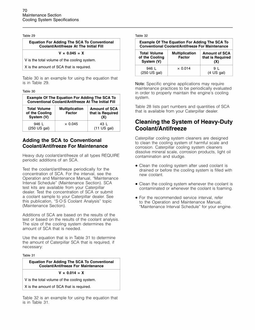
70Maintenance SectionCooling System Specifications
Table 29
Equation For Adding The SCA To ConventionalCoolant/Antifreeze At The Initial Fill
V × 0.045 = X
V is the total volume of the cooling system.
X is the amount of SCA that is required.
Table 30 is an example for using the equation thatis in Table 29.
Table 30
Example Of The Equation For Adding The SCA ToConventional Coolant/Antifreeze At The Initial Fill
Total Volumeof the Cooling
System (V)
MultiplicationFactor
Amount of SCAthat is Required
(X)
946 L(250 US gal)
× 0.045 43 L(11 US gal)
Adding the SCA to ConventionalCoolant/Antifreeze For Maintenance
Heavy duty coolant/antifreeze of all types REQUIREperiodic additions of an SCA.
Test the coolant/antifreeze periodically for theconcentration of SCA. For the interval, see theOperation and Maintenance Manual, “MaintenanceInterval Schedule” (Maintenance Section). SCAtest kits are available from your Caterpillardealer. Test the concentration of SCA or submita coolant sample to your Caterpillar dealer. Seethis publication, “S·O·S Coolant Analysis” topic(Maintenance Section).
Additions of SCA are based on the results of thetest or based on the results of the coolant analysis.The size of the cooling system determines theamount of SCA that is needed.
Use the equation that is in Table 31 to determinethe amount of Caterpillar SCA that is required, ifnecessary:
Table 31
Equation For Adding The SCA To ConventionalCoolant/Antifreeze For Maintenance
V × 0.014 = X
V is the total volume of the cooling system.
X is the amount of SCA that is required.
Table 32 is an example for using the equation thatis in Table 31.
Table 32
Example Of The Equation For Adding The SCA ToConventional Coolant/Antifreeze For Maintenance
Total Volumeof the Cooling
System (V)
MultiplicationFactor
Amount of SCAthat is Required
(X)
946 L(250 US gal)
× 0.014 9 L(4 US gal)
Note: Specific engine applications may requiremaintenance practices to be periodically evaluatedin order to properly maintain the engine’s coolingsystem.
Table 28 lists part numbers and quantities of SCAthat is available from your Caterpillar dealer.
Cleaning the System of Heavy-DutyCoolant/Antifreeze
Caterpillar cooling system cleaners are designedto clean the cooling system of harmful scale andcorrosion. Caterpillar cooling system cleanersdissolve mineral scale, corrosion products, light oilcontamination and sludge.
• Clean the cooling system after used coolant isdrained or before the cooling system is filled withnew coolant.
• Clean the cooling system whenever the coolant iscontaminated or whenever the coolant is foaming.
• For the recommended service interval, referto the Operation and Maintenance Manual,“Maintenance Interval Schedule” for your engine.

71Maintenance Section
Refill Capacities
Refill Capacities
i01539748
Refill CapacitiesSMCS Code: 1348; 1395; 7560
Lubrication System
The refill capacities for the engine crankcasereflect the approximate capacity of the crankcaseor sump plus standard oil filters. Auxiliary oil filtersystems will require additional oil. Refer to theOEM specifications for the capacity of the auxiliaryoil filter. Refer to the Operation and MaintenanceManual, “Lubricant Specifications” (MaintenanceSection) for more information.
Table 33
C-9 Industrial EngineApproximate Refill Capacities
Refill Capacity forChanging the Oil
and the Filter
Liters Quarts
Oil Sump(1) 31 33
(1) These values should be inserted by the customer asapproximate capacities for the crankcase oil sump whichinclude the standard oil filters that are installed at the factory.Engines with auxiliary oil filters will require additional oil. Referto the OEM specifications for the capacity of the auxiliary oilfilter.
Cooling System
To maintain the cooling system, the Total CoolingSystem capacity must be known. The capacity ofthe Total Cooling System will vary. The capacitywill depend on the size of the radiator (capacity)that is provided by the vehicle manufacturer. Table34 should be completed by the customer for themaintenance of the cooling system. Refer to theOperation and Maintenance Manual, “CoolingSystem Specifications” (Maintenance Section) formore information.
Table 34
C-9 Industrial EngineApproximate Refill Capacities
Compartment or System Liters Quarts
Total Cooling System

72Maintenance SectionMaintenance Interval Schedule
i01660955
Maintenance Interval ScheduleSMCS Code: 1000; 7500
Operating conditions and oil API Classificationswill determine the amount of service hours for thePM Level 1 Maintenance Interval Schedule. Referto Operation and Maintenance Manual, “Engine Oiland Filter - Change” for your specific oil changeinterval.
Note: Ensure that the Safety Information, warnings,and instructions are read and understoodbefore operation or maintenance procedures areperformed.
Note: Use fuel consumption, service hours, orcalendar time, whichever occurs first in order todetermine the maintenance intervals. Engines thatoperate in severe operating conditions may requiremore frequent maintenance.
Before each consecutive interval is performed, allof the maintenance requirements from the previousinterval must also be performed.
When Required
Battery - Replace .................................................. 76Battery or Battery Cable - Disconnect .................. 77Engine Air Cleaner Element (Dual Element) -Clean/Replace .................................................... 88
Engine Storage Procedure - Check ...................... 97Ether Starting Aid Cylinder - Replace ................... 98Fuel System - Prime ............................................. 98Severe Service Application - Check .................... 107
Daily
Air Tank Moisture and Sediment - Drain ............... 76Cooling System Coolant Level - Check ................ 84Driven Equipment - Check .................................... 87Engine Air Cleaner Service Indicator - Inspect ..... 90Engine Oil Level - Check ...................................... 92Fuel System Primary Filter/Water Separator -Drain ................................................................... 99
Power Take-Off Clutch - Check/Adjust/Lubricate ........................................................... 106
Walk-Around Inspection ...................................... 109
Initial 20 to 40 Service Hours
Belt - Inspect ......................................................... 78
Every Week
Battery Charger - Check ....................................... 78Jacket Water Heater - Check .............................. 103
Initial 500 Service Hours
Engine Valve Lash - Inspect/Adjust ...................... 97
Every 6000 Service Hours or 6 Years
Cooling System Coolant (ELC) - Change ............. 82
PM Level 1 - Every 10 400 L (2750 US gal) ofFuel or 250 Service Hours or 6 Months
Air Compressor Filter - Clean/Replace ................. 75Battery Electrolyte Level - Check .......................... 77Cooling System Supplemental Coolant Additive(SCA) - Test/Add ................................................. 85
Engine Oil Sample - Obtain .................................. 92Engine Oil and Filter - Change ............................. 93Fan Drive Bearing - Lubricate ............................... 98Fuel System Primary Filter/Water Separator Element- Replace ........................................................... 100
Fuel System Secondary Filter - Replace ............ 101Fuel Tank Water and Sediment - Drain ............... 102Hoses and Clamps - Inspect/Replace ................ 102Radiator - Clean .................................................. 107
PM Level 1 - Every 20 800 L (5500 US gal) ofFuel or 500 Service Hours or 6 Months
Air Compressor Filter - Clean/Replace ................. 75Battery Electrolyte Level - Check .......................... 77Cooling System Supplemental Coolant Additive(SCA) - Test/Add ................................................. 85
Engine Oil Sample - Obtain .................................. 92Engine Oil and Filter - Change ............................. 93Fan Drive Bearing - Lubricate ............................... 98Fuel System Primary Filter/Water Separator Element- Replace ........................................................... 100
Fuel System Secondary Filter - Replace ............ 101Fuel Tank Water and Sediment - Drain ............... 102Hoses and Clamps - Inspect/Replace ................ 102Radiator - Clean .................................................. 107
PM Level 2 - Every 83 250 L (22 000 US gal)of Fuel or 2000 Service Hours or 1 Year
Aftercooler Core - Inspect ..................................... 74Alternator - Inspect ............................................... 76Engine Crankcase Breather - Clean ..................... 91Engine Valve Lash - Inspect/Adjust ...................... 97Engine Valve Rotators - Inspect ............................ 97
PM Level 3 - Every 166 500 L (44 000 US gal)of Fuel or 4000 Service Hours or 2 Years
Aftercooler Core - Clean/Test ............................... 74Air Compressor - Inspect ...................................... 75Belt Tensioner - Inspect ........................................ 80Cooling System Coolant (DEAC) - Change .......... 80Cooling System Coolant Extender (ELC) - Add .... 84Cooling System Water Temperature Regulator -Replace ............................................................... 86
Crankshaft Vibration Damper - Inspect ................. 86

73Maintenance Section
Maintenance Interval Schedule
Engine - Clean ...................................................... 87Engine Mounts - Inspect ....................................... 91
Every 340 000 L (90 000 US gal) of Fuel or10 000 Service Hours
Cylinder Head Grounding Stud - Inspect/Clean/Tighten ................................................................ 87
Overhaul Considerations .................................... 103
Every 208 000 L (55 000 US gal) of Fuel or5000 Service Hours
Starting Motor - Inspect ...................................... 108Turbocharger - Inspect ........................................ 108Water Pump - Inspect ......................................... 110
74Maintenance SectionAftercooler Core - Clean/Test
i01546702
Aftercooler Core - Clean/TestSMCS Code: 1064-070; 1064-081
1. Remove the core. Refer to the Service Manualfor the procedure.
2. Turn the aftercooler core upside-down in orderto remove debris.
NOTICEDo not use a high concentration of caustic cleaner toclean the core. A high concentration of caustic cleanercan attack the internal metals of the core and causeleakage. Only use the recommended concentration ofcleaner.
3. Back flush the core with cleaner.
Caterpillar recommends the use of Hydrosolvliquid cleaner. Table 35 lists Hydrosolv liquidcleaners that are available from your Caterpillardealer.
Table 35
Hydrosolv Liquid Cleaners(1)
PartNumber Description Size
1U-5490 Hydrosolv 4165 19 L (5 US gallon)
174-6854 Hydrosolv 100 19 L (5 US gallon)
(1) Use a two to five percent concentration of the cleanerat temperatures up to 93�C (200�F). Refer to ApplicationGuide, NEHS0526 or consult your Caterpillar dealer for moreinformation.
4. Steam clean the core in order to remove anyresidue. Flush the fins of the aftercooler core.Remove any other trapped debris.
5. Wash the core with hot, soapy water. Rinse thecore thoroughly with clean water.
Personal injury can result from air pressure.
Personal injury can result without following prop-er procedure. When using pressure air, wear a pro-tective face shield and protective clothing.
Maximum air pressure at the nozzle must be lessthan 205 kPa (30 psi) for cleaning purposes.
6. Dry the core with compressed air. Direct the airin the reverse direction of the normal flow.
7. Inspect the core in order to ensure cleanliness.Pressure test the core. Many shops that serviceradiators are equipped to perform pressure tests.If necessary, repair the core.
8. Install the core. Refer to the Service Manual forthe procedure.
For more information on cleaning the core, consultyour Caterpillar dealer.
i01468985
Aftercooler Core - InspectSMCS Code: 1064-040
Note: Adjust the frequency of cleaning according tothe effects of the operating environment.
Inspect the aftercooler for these items: damagedfins, corrosion, dirt, grease, insects, leaves, oil, andother debris. Clean the aftercooler, if necessary.
For air-to-air aftercoolers, use the same methodsthat are used for cleaning radiators.
Personal injury can result from air pressure.
Personal injury can result without following prop-er procedure. When using pressure air, wear a pro-tective face shield and protective clothing.
Maximum air pressure at the nozzle must be lessthan 205 kPa (30 psi) for cleaning purposes.
Pressurized air is the preferred method for removingloose debris. Direct the air in the opposite directionof the fan’s air flow. Hold the nozzle approximately6 mm (.25 inch) away from the fins. Slowly movethe air nozzle in a direction that is parallel with thetubes. This will remove debris that is between thetubes.
Pressurized water may also be used for cleaning.The maximum water pressure for cleaning purposesmust be less than 275 kPa (40 psi). Use pressurizedwater in order to soften mud. Clean the core fromboth sides.
Use a degreaser and steam for removal of oil andgrease. Clean both sides of the core. Wash the corewith detergent and hot water. Thoroughly rinse thecore with clean water.

75Maintenance Section
Air Compressor - Inspect
After cleaning, start the engine and accelerate theengine to high idle rpm. This will help in the removalof debris and drying of the core. Stop the engine.Use a light bulb behind the core in order to inspectthe core for cleanliness. Repeat the cleaning, ifnecessary.
Inspect the fins for damage. Bent fins may beopened with a “comb”.
Note: If parts of the aftercooler system are repairedor replaced, a leak test is highly recommended.The FT1984 Aftercooler Testing Group is usedto perform leak tests on the aftercooler. Refer tothe Systems Operation/Testing and Adjusting,“Aftercooler - Test” and the Special Instruction,SEHS8622 for the proper testing procedure.
Inspect these items for good condition: welds,mounting brackets, air lines, connections, clamps,and seals. Make repairs, if necessary.
For more detailed information on cleaning andinspection, see Special Publication, SEBD0518,“Know Your Cooling System”.
i01183385
Air Compressor - InspectSMCS Code: 1803-040
Do not disconnect the air line from the air com-pressor governor without purging the air brakeand the auxiliary air systems. Failure to purge theair brake and the auxiliary air systems before re-moving the air compressor and/or the air linescould cause personal injury.
g00633741Illustration 31
(1) Air compressor pressure relief valve
If the air compressor pressure relief valve that ismounted in the air compressor cylinder head isbypassing compressed air, there is a malfunctionin the air system, possibly ice blockage. Underthese conditions, your engine may have insuffi-cient air for normal brake operation.
Do not operate the engine until the reason for theair bypass is identified and corrected. Failure toheed this warning could lead to property damage,personal injury, or death to the operator or by-standers.
The function of the air compressor pressure reliefvalve is to bypass air when there is a malfunction inthe air compressor system.
The air compressor pressure relief valve releasesair at 1723 kPa (250 psi). It is very important thatall personnel stand clear of the air compressorpressure relief valve when compressed air isreleased. All personnel should also stay clear of theair compressor when the engine is operating andthe air compressor is exposed.
Refer to the Service Manual or refer to the OEMspecifications in order to find information concerningthe air compressor. Consult your Caterpillar dealerfor assistance.
i01544231
Air Compressor Filter -Clean/Replace(If Equipped)SMCS Code: 1803-070-FQ; 1803-510-FQ
One of the single most important aspects ofpreventive maintenance for the air compressor isthe induction of clean air. The type of maintenancethat is required for the air compressor and themaintenance interval depends on the type of airinduction system that is used. Operating conditions(dust, dirt and debris) may require more frequentservice.
Refer to the Service Manual for the type ofair compressor that is installed on the engine.Follow the maintenance recommendations that areprovided by the OEM of the air compressor. Someengines use boost air pressure so the engine aircleaner will require servicing.

76Maintenance SectionAir Tank Moisture and Sediment - Drain
i00847451
Air Tank Moisture andSediment - Drain(If Equipped)SMCS Code: 1466-543-M&S
Moisture and sediment in the air starting systemcan cause the following conditions:
• Freezing
• Corrosion of internal parts
• Malfunction of the air starting system
When opening the drain valve, wear protectivegloves, a protective face shield, protective cloth-ing, and protective shoes. Pressurized air couldcause debris to be blown and result in personalinjury.
1. Open the drain valve that is on the bottom ofthe air tank. Allow the moisture and sedimentto drain.
2. Close the drain valve.
3. Check the air supply pressure. The air startingmotor requires a minimum of 620 kPa (90 psi) ofair pressure to operate properly. The maximumair pressure must not exceed 1550 kPa (225 psi).The normal air pressure will be 758 to 965 kPa(110 to 140 psi).
i00072207
Alternator - InspectSMCS Code: 1405-040
Caterpillar recommends a scheduled inspectionof the alternator. Inspect the alternator for looseconnections and proper battery charging. Inspectthe ammeter (if equipped) during engine operationin order to ensure proper battery performanceand/or proper performance of the electrical system.Make repairs, as required. Refer to the ServiceManual.
Check the alternator and the battery charger forproper operation. If the batteries are properlycharged, the ammeter reading should be very nearzero. All batteries should be kept charged. Thebatteries should be kept warm because temperatureaffects the cranking power. If the battery is too cold,the battery will not crank the engine. The battery willnot crank the engine, even if the engine is warm.When the engine is not run for long periods of timeor if the engine is run for short periods, the batteriesmay not fully charge. A battery with a low charge willfreeze more easily than a battery with a full charge.
i01492550
Battery - ReplaceSMCS Code: 1401-510
Batteries give off combustible gases which canexplode. A spark can cause the combustible gas-es to ignite. This can result in severe personal in-jury or death.
Ensure proper ventilation for batteries that are inan enclosure. Follow the proper procedures in or-der to help prevent electrical arcs and/or sparksnear batteries. Do not smoke when batteries areserviced.
The battery cables or the batteries should not beremoved with the battery cover in place. The bat-tery cover should be removed before any servic-ing is attempted.
Removing the battery cables or the batteries withthe cover in place may cause a battery explosionresulting in personal injury.
1. Turn the key start switch to the OFF position.Remove the key and all electrical loads.
2. Turn OFF the battery charger. Disconnect thecharger.
3. The NEGATIVE “-” cable connects the NEGATIVE“-” battery terminal to the ground plane.Disconnect the cable from the NEGATIVE “-”battery terminal.
4. The POSITIVE “+” cable connects the POSITIVE“+” battery terminal to the starting motor.Disconnect the cable from the POSITIVE “+”battery terminal.

77Maintenance Section
Battery Electrolyte Level - Check
Note: Always recycle a battery. Never discard abattery. Return used batteries to an appropriaterecycling facility.
5. Remove the used battery.
6. Install the new battery.
Note: Before the cables are connected, ensure thatthe key start switch is OFF.
7. Connect the cable from the starting motor to thePOSITIVE “+” battery terminal.
8. Connect the cable from the ground plane to theNEGATIVE “-” battery terminal.
i01639002
Battery Electrolyte Level -CheckSMCS Code: 1401-535
When the engine is not run for long periods oftime or when the engine is run for short periods,the batteries may not fully recharge. Ensure a fullcharge in order to help prevent the battery fromfreezing. If batteries are properly charged, ammeterreading should be very near zero.
All lead-acid batteries contain sulfuric acid whichcan burn the skin and clothing. Always wear a faceshield and protective clothing when working on ornear batteries.
1. Remove the filler caps. Maintain the electrolytelevel to the “FULL” mark on the battery.
If the addition of water is necessary, use distilledwater. If distilled water is not available useclean water that is low in minerals. Do not useartificially softened water.
2. Check the condition of the electrolyte with the1U-7298 Coolant/Battery Tester (�C) or the1U-7297 Coolant/Battery Tester (�F).
3. Keep the batteries clean.
Clean the battery case with one of the followingcleaning solutions:
• A mixture of 0.1 kg (0.2 lb) of baking soda and1 L (1 qt) of clean water
• A mixture of 0.1 L (0.11 qt) of ammonia and1 L (1 qt) of clean water
Thoroughly rinse the battery case with cleanwater.
Use a fine grade of sandpaper to clean theterminals and the cable clamps. Clean the itemsuntil the surfaces are bright or shiny. DO NOTremove material excessively. Excessive removalof material can cause the clamps to not fitproperly. Coat the clamps and the terminals with5N-5561 Silicone Lubricant, petroleum jelly orMPGM grease.
i01492654
Battery or Battery Cable -DisconnectSMCS Code: 1402-029
The battery cables or the batteries should not beremoved with the battery cover in place. The bat-tery cover should be removed before any servic-ing is attempted.
Removing the battery cables or the batteries withthe cover in place may cause a battery explosionresulting in personal injury.
1. Turn the start switch to the OFF position. Turn theignition switch (if equipped) to the OFF positionand remove the key and all electrical loads.
2. Disconnect the negative battery terminal at thebattery that goes to the start switch. Ensure thatthe cable cannot contact the terminal. When four12 volt batteries are involved, the negative sideof two batteries must be disconnected.
3. Tape the leads in order to help prevent accidentalstarting.
4. Proceed with necessary system repairs. Reversethe steps in order to reconnect all of the cables.

78Maintenance SectionBattery Charger - Check
i01039758
Battery Charger - CheckSMCS Code: 1401-535
Checking Before Start-Up
Check the battery charger for proper operation. Ifthe batteries are properly charged, the needle ofthe ammeter will register near “0” (zero).
The battery charger must not produce excessivecurrent during start-up. Alternatively, the chargermust be automatically disconnected for start-up.If the engine has an alternator, the charger mustbe automatically disconnected during start-up andduring engine operation.
Charging the Battery
Never disconnect any charging unit circuit or bat-tery circuit cable from the battery when the charg-ing unit is operated. A spark can cause an explo-sion from the flammable vapor mixture of hydro-gen and oxygen that is released from the elec-trolyte through the battery outlets. Injury to per-sonnel can be the result.
Perform the following procedure to charge thebattery:
1. Ensure that the charger is turned OFF.
2. Adjust the voltage of the charger in order tomatch the voltage of the battery.
3. Connect the POSITIVE “+” lead of the chargerto the POSITIVE “+” battery terminal. Connectthe NEGATIVE “-” lead of the charger to theNEGATIVE “-” battery terminal.
4. Turn ON the battery charger.
Overcharging of Batteries
Overcharging reduces the service life of batteries.Use a battery charger that will not overcharge thebattery. DO NOT charge the battery if the meter ofthe battery charger is in the RED zone.
Overcharging is indicated by the followingsymptoms:
• The battery is very warm to the touch.
• A strong odor of acid is present.
• The battery emits smoke or a dense vapor (gas).
Perform one of the following procedures if thebattery shows symptoms of overcharging:
• Reduce the rate of charging by a significantamount. Complete the charging at the reducedrate.
• Turn OFF the charger.
Table 36 describes the effects of overcharging ondifferent types of batteries.
Table 36
Effects of Overcharging Batteries
Type of Battery Effect
All of the battery cells havea low level of electrolyte.
When the plates of thebattery are inspectedthrough the filler holes, theplates may appear to bewarped. This is caused byan excessive temperature.
Caterpillar General ServiceBatteriesCaterpillar Premium HighOutput Batteries
The battery may not passa load test.
The battery may not accepta charging current.
Caterpillar MaintenanceFree Batteries
The battery may not passa load test.
Checking After Stopping
Ensure that the battery charger is connectedproperly. Observe the meter of the charger. Recordthe amperage.
i01539754
Belt - InspectSMCS Code: 1357-040; 1357; 1397-040; 1397
Inspection
Belt tension should be checked initially betweenthe first 20 to 40 hours of engine operation.
After the initial check, the belt tension should bechecked at every oil change.

79Maintenance Section
Belt - Inspect
To maximize the engine performance, inspect thebelts for wear and for cracking. Replace belts thatare worn or damaged.
For applications that require multiple drive belts,replace the belts in matched sets. Replacing onlyone belt of a matched set will cause the new belt tocarry more load because the older belt is stretched.The additional load on the new belt could cause thenew belt to break.
If the belts are too loose, vibration causesunnecessary wear on the belts and pulleys. Loosebelts may slip enough to cause overheating.
If the belts are too tight, unnecessary stresses areplaced on the pulley bearings and on the belts. Thismay shorten the service life of the components.
Remove the belt guard, if equipped. Inspect thecondition and adjustment of the alternator belts andaccessory drive belts (if equipped).
To check the belt tension, apply 110 N (25 lb ft)of force midway between the pulleys. A correctlyadjusted belt will deflect 9 mm (0.35 inch) to 15 mm(0.59 inch).
If the belt does not require replacement oradjustment, install the belt guard. If the belt requiresadjustment or replacement, perform the followingprocedure to adjust the belt tension.
Adjustment
Alternator Belt
g00768640Illustration 32
(1) Nut(2) Adjusting Nut(3) Bolt(4) Nut
1. Slightly loosen mounting bolt (3) and nut (4).
2. Loosen nut (1).
3. Tighten adjusting bolt (2) and mounting bolts(3) and (4). Tighten bolt (1). Refer to theOperation and Maintenance Manual, “TorqueSpecifications” topic (Maintenance Section).
If new belts are installed, check the belt tensionagain after 30 minutes of engine operation at therated rpm.

80Maintenance SectionBelt Tensioner - Inspect
Water Pump Belt
g00426869Illustration 33
Typical example
Exploded view of the drive assembly for a water pump belt
(1) Mounting bolt(2) Square hole(3) Adjusting bolt
1. Slightly loosen mounting bolt (1) and adjustingbolt (3).
2. Adjust the belt tension with a square drive insquare hole (2).
3. Tighten adjusting bolt (3) and mounting bolt (1).Refer to the Operation and Maintenance Manual,“Torque Specifications” topic (MaintenanceSection).
4. Install the belt guard, if equipped.
If new belts are installed, check the belt tension after30 minutes of engine operation at the rated rpm.
i01555583
Belt Tensioner - Inspect(If Equipped)SMCS Code: 1358-040
g00426964Illustration 34
Belt tensioner
Inspect the belt tensioner for unusual noise,excessive looseness and/or shaking of the bearings.
If the belt tensioner should require disassembly,refer to the Service Manual for the procedure.
i01206425
Cooling System Coolant(DEAC) - ChangeSMCS Code: 1350-070; 1395-044
Clean the cooling system and flush the coolingsystem before the recommended maintenanceinterval if the following conditions exist:
• The engine overheats frequently.
• Foaming is observed.
• The oil has entered the cooling system and thecoolant is contaminated.
• The fuel has entered the cooling system and thecoolant is contaminated.
NOTICEUse of commercially available cooling system clean-ers may cause damage to cooling system compo-nents. Use only cooling system cleaners that are ap-proved for Caterpillar engines.

81Maintenance Section
Cooling System Coolant (DEAC) - Change
Note: Inspect the water pump and the watertemperature regulator after the cooling system hasbeen drained. This is a good opportunity to replacethe water pump, the water temperature regulatorand the hoses, if necessary.
Drain
Pressurized System: Hot coolant can cause seri-ous burns. To open the cooling system filler cap,stop the engine and wait until the cooling systemcomponents are cool. Loosen the cooling systempressure cap slowly in order to relieve the pres-sure.
1. Stop the engine and allow the engine to cool.Loosen the cooling system filler cap slowlyin order to relieve any pressure. Remove thecooling system filler cap.
2. Open the cooling system drain valve (ifequipped). If the cooling system is not equippedwith a drain valve, remove one of the drain plugs.
Allow the coolant to drain.
NOTICEDispose of used engine coolant properly or recycle.Various methods have been proposed to reclaim usedcoolant for reuse in engine cooling systems. The fulldistillation procedure is the only method acceptable byCaterpillar to reclaim the used coolant.
For information regarding the disposal and therecycling of used coolant, consult your Caterpillardealer or consult Caterpillar Service TechnologyGroup:
Outside Illinois: 1-800-542-TOOLInside Illinois: 1-800-541-TOOLCanada: 1-800-523-TOOL
Flush
1. Flush the cooling system with clean water inorder to remove any debris.
2. Close the drain valve (if equipped). Clean thedrain plugs. Install the drain plugs. Refer to theOperation and Maintenance Manual, “TorqueSpecifications” topic (Maintenance Section) formore information on the proper torques.
NOTICEFill the cooling system no faster than 19 L (5 US gal)per minute to avoid air locks.
3. Fill the cooling system with a mixture of cleanwater and Caterpillar Fast Acting Cooling SystemCleaner. Add 0.5 L (1 pint) of cleaner per 15 L(4 US gal) of the cooling system capacity. Installthe cooling system filler cap.
4. Start and run the engine at low idle for aminimum of 30 minutes. The coolant temperatureshould be at least 82 �C (180 �F).
NOTICEImproper or incomplete rinsing of the cooling systemcan result in damage to copper and other metal com-ponents.
To avoid damage to the cooling system, make sureto completely flush the cooling system with clear wa-ter. Continue to flush the system until all signs of thecleaning agent are gone.
5. Stop the engine and allow the engine to cool.Loosen the cooling system filler cap slowlyin order to relieve any pressure. Remove thecooling system filler cap. Open the drain valve(if equipped) or remove the cooling systemdrain plugs. Allow the water to drain. Flush thecooling system with clean water. Close the drainvalve (if equipped). Clean the drain plugs. Installthe drain plugs. Refer to the Operation andMaintenance Manual, “Torque Specifications”topic (Maintenance Section) for more informationon the proper torques.
Cooling Systems with HeavyDeposits or Plugging
Note: For the following procedure to be effective,there must be some active flow through the coolingsystem components.
1. Flush the cooling system with clean water inorder to remove any debris.
2. Close the drain valve (if equipped). Clean thedrain plugs. Install the drain plugs. Refer to theOperation and Maintenance Manual, “TorqueSpecifications” topic (Maintenance Section) formore information on the proper torques.
NOTICEFill the cooling system no faster than 19 L (5 US gal)per minute to avoid air locks.
3. Fill the cooling system with a mixture of cleanwater and Caterpillar Fast Acting Cooling SystemCleaner. Add 0.5 L (1 pint) of cleaner per3.8 to 7.6 L (1 to 2 US gal) of the cooling systemcapacity. Install the cooling system filler cap.

82Maintenance SectionCooling System Coolant (ELC) - Change
4. Start and run the engine at low idle for aminimum of 90 minutes. The coolant temperatureshould be at least 82 �C (180 �F).
NOTICEImproper or incomplete rinsing of the cooling systemcan result in damage to copper and other metal com-ponents.
To avoid damage to the cooling system, make sureto completely flush the cooling system with clear wa-ter. Continue to flush the system until all signs of thecleaning agent are gone.
5. Stop the engine and allow the engine to cool.Loosen the cooling system filler cap slowlyin order to relieve any pressure. Remove thecooling system filler cap. Open the drain valve(if equipped) or remove the cooling systemdrain plugs. Allow the water to drain. Flush thecooling system with clean water. Close the drainvalve (if equipped). Clean the drain plugs. Installthe drain plugs. Refer to the Operation andMaintenance Manual, “Torque Specifications”topic (Maintenance Section) for more informationon the proper torques.
Fill
NOTICEFill the cooling system no faster than 19 L (5 US gal)per minute to avoid air locks.
1. Fill the cooling system with coolant/antifreeze.Refer to the Operation and MaintenanceManual, “Cooling System Specifications” topic(Maintenance Section) for more information oncooling system specifications. Do not install thecooling system filler cap.
2. Start and run the engine at low idle. Increase theengine rpm to 1500 rpm. Run the engine at highidle for one minute in order to purge the air fromthe cavities of the engine block. Stop the engine.
3. Check the coolant level. Maintain the coolantlevel within 13 mm (0.5 inch) below the bottomof the pipe for filling. Maintain the coolant levelwithin 13 mm (0.5 inch) to the proper level on thesight glass (if equipped).
4. Clean the cooling system filler cap. Inspect thegasket that is on the cooling system filler cap. Ifthe gasket that is on the cooling system filler capis damaged, discard the old cooling system fillercap and install a new cooling system filler cap.If the gasket that is on the cooling system fillercap is not damaged, perform a pressure test. A9S-8140 Pressurizing Pump is used to performthe pressure test. The correct pressure for thecooling system filler cap is stamped on the faceof the cooling system filler cap. If the coolingsystem filler cap does not retain the correctpressure, install a new cooling system filler cap.
5. Start the engine. Inspect the cooling system forleaks and for proper operating temperature.
i01206445
Cooling System Coolant (ELC)- ChangeSMCS Code: 1350-070; 1395-044
Clean the cooling system and flush the coolingsystem before the recommended maintenanceinterval if the following conditions exist:
• The engine overheats frequently.
• Foaming is observed.
• The oil has entered the cooling system and thecoolant is contaminated.
• The fuel has entered the cooling system and thecoolant is contaminated.
Note: When the cooling system is cleaned, onlyclean water is needed when the ELC is drainedand replaced.
Note: Inspect the water pump and the watertemperature regulator after the cooling system hasbeen drained. This is a good opportunity to replacethe water pump, the water temperature regulatorand the hoses, if necessary.
Drain
Pressurized System: Hot coolant can cause seri-ous burns. To open the cooling system filler cap,stop the engine and wait until the cooling systemcomponents are cool. Loosen the cooling systempressure cap slowly in order to relieve the pres-sure.
83Maintenance Section
Cooling System Coolant (ELC) - Change
1. Stop the engine and allow the engine to cool.Loosen the cooling system filler cap slowlyin order to relieve any pressure. Remove thecooling system filler cap.
2. Open the cooling system drain valve (ifequipped). If the cooling system is not equippedwith a drain valve, remove the cooling systemdrain plugs.
Allow the coolant to drain.
NOTICEDispose of used engine coolant properly or recycle.Various methods have been proposed to reclaim usedcoolant for reuse in engine cooling systems. The fulldistillation procedure is the only method acceptable byCaterpillar to reclaim the used coolant.
For information regarding the disposal and therecycling of used coolant, consult your Caterpillardealer or consult Caterpillar Service TechnologyGroup:
Outside Illinois: 1-800-542-TOOLInside Illinois: 1-800-541-TOOLCanada: 1-800-523-TOOL
Flush
1. Flush the cooling system with clean water inorder to remove any debris.
2. Close the drain valve (if equipped). Clean thedrain plugs. Install the drain plugs. Refer to theOperation and Maintenance Manual, “TorqueSpecifications” topic (Maintenance Section) formore information on the proper torques.
NOTICEFill the cooling system no faster than 19 L (5 US gal)per minute to avoid air locks.
3. Fill the cooling system with clean water. Installthe cooling system filler cap.
4. Start and run the engine at low idle until thetemperature reaches 49 to 66 �C (120 to 150 �F).
5. Stop the engine and allow the engine to cool.Loosen the cooling system filler cap slowlyin order to relieve any pressure. Remove thecooling system filler cap. Open the drain valve(if equipped) or remove the cooling systemdrain plugs. Allow the water to drain. Flush thecooling system with clean water. Close the drainvalve (if equipped). Clean the drain plugs. Installthe drain plugs. Refer to the Operation andMaintenance Manual, “Torque Specifications”topic (Maintenance Section) for more informationon the proper torques.
Fill
NOTICEFill the cooling system no faster than 19 L (5 US gal)per minute to avoid air locks.
1. Fill the cooling system with Extended Life Coolant(ELC). Refer to the Operation and MaintenanceManual, “Cooling System Specifications” topic(Maintenance Section) for more information oncooling system specifications. Do not install thecooling system filler cap.
2. Start and run the engine at low idle. Increase theengine rpm to high idle. Run the engine at highidle for one minute in order to purge the air fromthe cavities of the engine block. Stop the engine.
3. Check the coolant level. Maintain the coolantlevel within 13 mm (0.5 inch) below the bottomof the pipe for filling. Maintain the coolant levelwithin 13 mm (0.5 inch) to the proper level on thesight glass (if equipped).
4. Clean the cooling system filler cap. Inspect thegasket that is on the cooling system filler cap. Ifthe gasket that is on the cooling system filler capis damaged, discard the old cooling system fillercap and install a new cooling system filler cap. Ifthe gasket that is on the cooling system filler capis not damaged, use a 9S-8140 PressurizingPump in order to pressure test the coolingsystem filler cap. The correct pressure for thecooling system filler cap is stamped on the faceof the cooling system filler cap. If the coolingsystem filler cap does not retain the correctpressure, install a new cooling system filler cap.
5. Start the engine. Inspect the cooling system forleaks and for proper operating temperature.

84Maintenance SectionCooling System Coolant Extender (ELC) - Add
i00259474
Cooling System CoolantExtender (ELC) - AddSMCS Code: 1352-045; 1395-081
Caterpillar Extended Life Coolant (ELC) does notrequire the frequent Supplemental Coolant Additive(SCA) additions associated with the presentconventional coolants. The Extender only needs tobe added once.
Check the cooling system only when the engine isstopped and cool.
1. Loosen the cooling system filler cap slowly inorder to relieve pressure. Remove the coolingsystem filler cap.
2. It may be necessary to drain enough coolantfrom the cooling system in order to add theExtender.
3. Add Extender according to the requirements foryour engine’s cooling system capacity. Refer tothe Operation and Maintenance Manual, “RefillCapacities” in the Maintenance Section for thecapacity of the cooling system for your engine.Refer to the Operation and Maintenance Manual,“Cooling System Specifications” information forthe Caterpillar ELC Extender additions.
4. Clean the cooling system filler cap. Inspect thecooling system filler cap gaskets. Replace thecooling system filler cap if the cooling systemfiller cap gaskets are damaged. Install thecooling system filler cap.
i01197583
Cooling System Coolant Level- CheckSMCS Code: 1395-082
Check the coolant level when the engine is stoppedand cool.
g00285520Illustration 35
Cooling system filler cap
Pressurized System: Hot coolant can cause seri-ous burns. To open the cooling system filler cap,stop the engine and wait until the cooling systemcomponents are cool. Loosen the cooling systempressure cap slowly in order to relieve the pres-sure.
1. Remove the cooling system filler cap slowly inorder to relieve pressure.
2. Maintain the coolant level within 13 mm (0.5 inch)of the bottom of the filler pipe. If the engine isequipped with a sight glass, maintain the coolantlevel to the proper level in the sight glass.
g00103639Illustration 36
Typical filler cap gaskets
3. Clean the cooling system filler cap and check thecondition of the filler cap gaskets. Replace thecooling system filler cap if the filler cap gasketsare damaged. Reinstall the cooling system fillercap.
4. Inspect the cooling system for leaks.

85Maintenance Section
Cooling System Supplemental Coolant Additive (SCA) - Test/Add
i01463635
Cooling System SupplementalCoolant Additive (SCA) -Test/AddSMCS Code: 1352-045; 1395-081
Cooling system coolant additive contains alkali.To help prevent personal injury, avoid contact withthe skin and the eyes. Do not drink cooling systemcoolant additive.
Note: Test the concentration of the SupplementalCoolant Additive (SCA) or test the SCA concentrationas part of an S·O·S Coolant Analysis.
Test for SCA Concentration
Coolant/Antifreeze and SCA
NOTICEDo not exceed the recommended six percent supple-mental coolant additive concentration.
Use the 8T-5296 Coolant Conditioner Test Kit oruse the 4C-9301 Coolant Conditioner Test Kit inorder to check the concentration of the SCA. Referto the Operation and Maintenance Manual for moreinformation.
Water and SCA
NOTICEDo not exceed the recommended eight percent sup-plemental coolant additive concentration.
Test the concentration of the SCA with the 8T-5296Coolant Conditioner Test Kit. Refer to the Operationand Maintenance Manual, “Water/SupplementalCoolant Additive (SCA)” topic (MaintenanceSection). Refer to the Operation and MaintenanceManual, “Conventional Coolant/Antifreeze CoolingSystem Maintenance” topic (Maintenance Section).
S·O·S Coolant Analysis
S·O·S coolant samples can be analyzed at yourCaterpillar dealer. S·O·S Coolant Analysis is aprogram that is based on periodic samples.
Level 1
Level 1 is a basic analysis of the coolant. Thefollowing items are tested:
• Glycol Concentration
• Concentration of SCA
• pH
• Conductivity
The results are reported, and recommendationsare made according to the results. Consult yourCaterpillar dealer for information on the benefits ofmanaging your equipment with an S·O·S CoolantAnalysis.
Level 2
This level coolant analysis is recommendedwhen the engine is overhauled. Refer to theOperations and Maintenance Manual, “OverhaulConsiderations” for further information.
Add the SCA, If Necessary
NOTICEDo not exceed the recommended amount of sup-plemental coolant additive concentration. Excessivesupplemental coolant additive concentration can formdeposits on the higher temperature surfaces of thecooling system, reducing the engine’s heat transfercharacteristics. Reduced heat transfer could causecracking of the cylinder head and other high temper-ature components. Excessive supplemental coolantadditive concentration could also result in radiatortube blockage, overheating, and/or accelerated waterpump seal wear. Never use both liquid supplementalcoolant additive and the spin-on element (if equipped)at the same time. The use of those additives togethercould result in supplemental coolant additive concen-tration exceeding the recommended maximum.
Pressurized System: Hot coolant can cause seri-ous burns. To open the cooling system filler cap,stop the engine and wait until the cooling systemcomponents are cool. Loosen the cooling systempressure cap slowly in order to relieve the pres-sure.
1. Slowly loosen the cooling system filler cap inorder to relieve the pressure. Remove the coolingsystem filler cap.

86Maintenance SectionCooling System Water Temperature Regulator - Replace
Note: Always discard drained fluids according tolocal regulations.
2. If necessary, drain some coolant from the coolingsystem into a suitable container in order to allowspace for the extra SCA.
3. Add the proper amount of SCA. Refer to theOperation and Maintenance Manual for moreinformation on SCA requirements.
4. Clean the cooling system filler cap. Inspect thegaskets of the cooling system filler cap. If thegaskets are damaged, replace the old coolingsystem filler cap with a new cooling system fillercap. Install the cooling system filler cap.
i00912898
Cooling System WaterTemperature Regulator -ReplaceSMCS Code: 1355-510
Replace the water temperature regulator beforethe water temperature regulator fails. This is arecommended preventive maintenance practice.Replacing the water temperature regulator reducesthe chances for unscheduled downtime.
A water temperature regulator that fails in apartially opened position can cause overheating orovercooling of the engine.
A water temperature regulator that fails in theclosed position can cause excessive overheating.Excessive overheating could result in cracking ofthe cylinder head or piston seizure problems.
A water temperature regulator that fails in the openposition will cause the engine operating temperatureto be too low during partial load operation. Lowengine operating temperatures during partial loadscould cause an excessive carbon buildup insidethe cylinders. This excessive carbon buildup couldresult in an accelerated wear of the piston rings andwear of the cylinder liner.
NOTICEFailure to replace your water temperature regulatoron a regularly scheduled basis could cause severeengine damage.
Caterpillar engines incorporate a shunt design coolingsystem and require operating the engine with a watertemperature regulator installed.
If the water temperature regulator is installed incor-rectly, the engine may overheat, causing cylinder headdamage. Ensure that the new water temperature reg-ulator is installed in the original position. Ensure thatthe water temperature regulator vent hole is open.
Do not use liquid gasket material on the gasket orcylinder head surface.
Refer to the Service Manual for the replacementprocedure of the water temperature regulator, orconsult your Caterpillar dealer.
Note: If only the water temperature regulators arereplaced, drain the coolant from the cooling systemto a level that is below the water temperatureregulator housing.
i00072369
Crankshaft Vibration Damper- InspectSMCS Code: 1205-040
Damage to the crankshaft vibration damper orfailure of the crankshaft vibration damper canincrease torsional vibrations. This can result indamage to the crankshaft and to other enginecomponents. A deteriorating damper can causeexcessive gear train noise at variable points in thespeed range.
The damper is mounted to the crankshaft which islocated behind the belt guard on the front of theengine.
Removal and Installation
Refer to the Service Manual for the damperremoval procedure and for the damper installationprocedure.

87Maintenance Section
Cylinder Head Grounding Stud - Inspect/Clean/Tighten
Visconic Damper
The visconic damper has a weight that is locatedinside a fluid filled case. The weight moves in thecase in order to limit torsional vibration. Inspectthe damper for evidence of dents, cracks or leaksof the fluid.
Replace the damper if the damper is dented,cracked or leaking. Refer to the Service Manualor consult your Caterpillar dealer for damperreplacement.
i01473487
Cylinder Head Grounding Stud- Inspect/Clean/TightenSMCS Code: 7423-040; 7423-070; 7423-079
g00768411Illustration 37
Typical example
Inspect the OEM harness for good connections andcondition.
The electrical grounding stud must have a wireground to the battery. Tighten the electricalgrounding stud at every oil change. Ground wiresand straps should be combined at engine grounds.All grounds should be tight and free of corrosion.
• If the connections are corroded, clean theconnections with a solution of baking soda andwater.
• Keep the electrical grounding stud and thestrap clean and coated with MPGM grease orpetroleum jelly.
i00174798
Driven Equipment - CheckSMCS Code: 3279-535
Refer to the OEM specifications for more informationon the following maintenance recommendations forthe driven equipment:
• Inspection
• Adjustment
• Lubrication
• Other maintenance recommendations
Perform any maintenance for the driven equipmentwhich is recommended by the OEM.
i01646701
Engine - CleanSMCS Code: 1000-070
Personal injury or death can result from high volt-age.
Moisture can create paths of electrical conductiv-ity.
Make sure that the electrical system is OFF. Lockout the starting controls and tag the controls “DONOT OPERATE”.
NOTICEAccumulated grease and oil on an engine is a fire haz-ard. Keep the engine clean. Remove debris and fluidspills whenever a significant quantity accumulates onthe engine.
Periodic cleaning of the engine is recommended.Steam cleaning the engine will remove accumulatedoil and grease. A clean engine provides thefollowing benefits:
• Easy detection of fluid leaks
• Maximum heat transfer characteristics
• Ease of maintenance
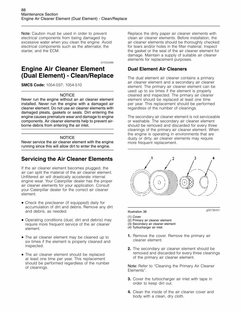
88Maintenance SectionEngine Air Cleaner Element (Dual Element) - Clean/Replace
Note: Caution must be used in order to preventelectrical components from being damaged byexcessive water when you clean the engine. Avoidelectrical components such as the alternator, thestarter, and the ECM.
i01553486
Engine Air Cleaner Element(Dual Element) - Clean/ReplaceSMCS Code: 1054-037; 1054-510
NOTICENever run the engine without an air cleaner elementinstalled. Never run the engine with a damaged aircleaner element. Do not use air cleaner elements withdamaged pleats, gaskets or seals. Dirt entering theengine causes premature wear and damage to enginecomponents. Air cleaner elements help to prevent air-borne debris from entering the air inlet.
NOTICENever service the air cleaner element with the enginerunning since this will allow dirt to enter the engine.
Servicing the Air Cleaner Elements
If the air cleaner element becomes plugged, theair can split the material of the air cleaner element.Unfiltered air will drastically accelerate internalengine wear. Your Caterpillar dealer has the properair cleaner elements for your application. Consultyour Caterpillar dealer for the correct air cleanerelement.
• Check the precleaner (if equipped) daily foraccumulation of dirt and debris. Remove any dirtand debris, as needed.
• Operating conditions (dust, dirt and debris) mayrequire more frequent service of the air cleanerelement.
• The air cleaner element may be cleaned up tosix times if the element is properly cleaned andinspected.
• The air cleaner element should be replacedat least one time per year. This replacementshould be performed regardless of the numberof cleanings.
Replace the dirty paper air cleaner elements withclean air cleaner elements. Before installation, theair cleaner elements should be thoroughly checkedfor tears and/or holes in the filter material. Inspectthe gasket or the seal of the air cleaner element fordamage. Maintain a supply of suitable air cleanerelements for replacement purposes.
Dual Element Air Cleaners
The dual element air cleaner contains a primaryair cleaner element and a secondary air cleanerelement. The primary air cleaner element can beused up to six times if the element is properlycleaned and inspected. The primary air cleanerelement should be replaced at least one timeper year. This replacement should be performedregardless of the number of cleanings.
The secondary air cleaner element is not serviceableor washable. The secondary air cleaner elementshould be removed and discarded for every threecleanings of the primary air cleaner element. Whenthe engine is operating in environments that aredusty or dirty, air cleaner elements may requiremore frequent replacement.
g00736431Illustration 38
(1) Cover(2) Primary air cleaner element(3) Secondary air cleaner element(4) Turbocharger air inlet
1. Remove the cover. Remove the primary aircleaner element.
2. The secondary air cleaner element should beremoved and discarded for every three cleaningsof the primary air cleaner element.
Note: Refer to “Cleaning the Primary Air CleanerElements”.
3. Cover the turbocharger air inlet with tape inorder to keep dirt out.
4. Clean the inside of the air cleaner cover andbody with a clean, dry cloth.

89Maintenance Section
Engine Air Cleaner Element (Dual Element) - Clean/Replace
5. Remove the tape for the turbocharger air inlet.Install the secondary air cleaner element. Installa primary air cleaner element that is new orcleaned.
6. Install the air cleaner cover.
7. Reset the air cleaner service indicator.
Cleaning the Primary Air CleanerElements
NOTICECaterpillar recommends certified air filter cleaningservices that are available at Caterpillar dealers. TheCaterpillar cleaning process uses proven proceduresto assure consistent quality and sufficient filter life.
Observe the following guidelines if you attempt toclean the filter element:
Do not tap or strike the filter element in order to removedust.
Do not wash the filter element.
Use low pressure compressed air in order to removethe dust from the filter element. Air pressure must notexceed 207 kPa (30 psi). Direct the air flow up thepleats and down the pleats from the inside of the filterelement. Take extreme care in order to avoid damageto the pleats.
Do not use air filters with damaged pleats, gaskets, orseals. Dirt entering the engine will cause damage toengine components.
The primary air cleaner element can be used upto six times if the element is properly cleaned andinspected. When the primary air cleaner element iscleaned, check for rips or tears in the filter material.The primary air cleaner element should be replacedat least one time per year. This replacementshould be performed regardless of the number ofcleanings.
Use clean primary air cleaner elements while dirtyelements are being cleaned.
NOTICEDo not clean the air cleaner elements by bumping ortapping. This could damage the seals. Do not use el-ements with damaged pleats, gaskets or seals. Dam-aged elements will allow dirt to pass through. Enginedamage could result.
Visually inspect the primary air cleaner elementsbefore cleaning. Inspect the air cleaner elementsfor damage to the seal, the gaskets, and the outercover. Discard any damaged air cleaner elements.
There are two common methods that are used toclean primary air cleaner elements:
• Pressurized air
• Vacuum cleaning
Pressurized Air
Pressurized air can be used to clean primary aircleaner elements that have not been cleaned morethan two times. Pressurized air will not removedeposits of carbon and oil. Use filtered, dry air witha maximum pressure of 207 kPa (30 psi).
g00281692Illustration 39
Note: When the primary air cleaner elements arecleaned, always begin with the clean side (inside)in order to force dirt particles toward the dirty side(outside).
Aim the hose so that the air flows inside the elementalong the length of the filter in order to help preventdamage to the paper pleats. Do not aim the streamof air directly at the primary air cleaner element. Dirtcould be forced further into the pleats.
Note: Refer to “Inspecting the Primary Air CleanerElements”.
Vacuum Cleaning
Vacuum cleaning is a good method for cleaningprimary air cleaner elements which require dailycleaning because of a dry, dusty environment.Cleaning with pressurized air is recommendedprior to vacuum cleaning. Vacuum cleaning will notremove deposits of carbon and oil.
Note: Refer to “Inspecting the Primary Air CleanerElements”.

90Maintenance SectionEngine Air Cleaner Service Indicator - Inspect
Inspecting the Primary Air CleanerElements
g00281693Illustration 40
Inspect the clean, dry primary air cleaner element.Use a 60 watt blue light in a dark room or in asimilar facility. Place the blue light in the primaryair cleaner element. Rotate the primary air cleanerelement. Inspect the primary air cleaner element fortears and/or holes. Inspect the primary air cleanerelement for light that may show through the filtermaterial. If it is necessary in order to confirm theresult, compare the primary air cleaner elementto a new primary air cleaner element that has thesame part number.
Do not use a primary air cleaner element that hasany tears and/or holes in the filter material. Do notuse a primary air cleaner element with damagedpleats, gaskets or seals. Discard damaged primaryair cleaner elements.
Storing Primary Air Cleaner Elements
If a primary air cleaner element that passesinspection will not be used, the primary air cleanerelement can be stored for future use.
g00281694Illustration 41
Do not use paint, a waterproof cover, or plastic as aprotective covering for storage. An airflow restrictionmay result. To protect against dirt and damage,wrap the primary air cleaner elements in VolatileCorrosion Inhibited (VCI) paper.
Place the primary air cleaner element into a boxfor storage. For identification, mark the outside ofthe box and mark the primary air cleaner element.Include the following information:
• Date of cleaning
• Number of cleanings
Store the box in a dry location.
i01175055
Engine Air Cleaner ServiceIndicator - InspectSMCS Code: 7452-040
Some engines may be equipped with a differentservice indicator.
Some engines are equipped with a differentialgauge for inlet air pressure. The differential gaugefor inlet air pressure displays the difference in thepressure that is measured before the air cleanerelement and the pressure that is measured afterthe air cleaner element. As the air cleaner elementbecomes dirty, the pressure differential rises. If yourengine is equipped with a different type of serviceindicator, follow the OEM recommendations in orderto service the air cleaner service indicator.
The service indicator may be mounted on the aircleaner element or in a remote location.
g00103777Illustration 42
Typical service indicator

91Maintenance Section
Engine Crankcase Breather - Clean
Observe the service indicator. The air cleanerelement should be cleaned or the air cleanerelement should be replaced when one of thefollowing conditions occur:
• The yellow diaphragm enters the red zone.
• The red piston locks in the visible position.
Test the Service Indicator
Service indicators are important instruments.
• Check for ease of resetting. The service indicatorshould reset in less than three pushes.
• Check the movement of the yellow core when theengine is accelerated to the engine rated speed.The yellow core should latch approximately at thegreatest vacuum that is attained.
If the service indicator does not reset easily, or if theyellow core does not latch at the greatest vacuum,the service indicator should be replaced. If thenew service indicator will not reset, the hole for theservice indicator may be plugged.
The service indicator may need to be replacedfrequently in environments that are severely dusty, ifnecessary. Replace the service indicator annuallyregardless of the operating conditions. Replace theservice indicator when the engine is overhauled,and whenever major engine components arereplaced.
Note: When a new service indicator is installed,excessive force may crack the top of the serviceindicator. Tighten the service indicator to a torqueof 2 N·m (18 lb in).
i01473536
Engine Crankcase Breather -CleanSMCS Code: 1317-070
NOTICEPerform this maintenance with the engine stopped.
NOTICEIf the crankcase breather is not maintained on aregular basis, it can become plugged. A pluggedbreather will cause excessive crankcase pressurethat may cause crankshaft seal leakage.
g00768439Illustration 43
(1) Breather assembly(2) Bolt(3) Hose clamp(4) Hose
1. Loosen hose clamp (3) and remove hose (4)from breather assembly (1).
2. Remove bolt (2) and the washer. Remove thebreather assembly (1) and the seal.
3. Wash the breather element in solvent that isclean and nonflammable. Allow the breatherelement to dry before installation.
4. Install a breather element that is clean and dry.Install breather assembly (1) and the seal.
5. Install bolt (2) and the washer. Refer to theOperation and Maintenance Manual for theproper torque.
6. Install hose (4) on breather assembly (1). Tightenhose clamp (3). Refer to the Operation andMaintenance Manual, “Torque Specifications” forthe proper torques.
i00687861
Engine Mounts - InspectSMCS Code: 1152-040
Inspect the engine mounts for deterioration and forproper bolt torque. Engine vibration can be causedby the following conditions:
• Improper mounting of the engine

92Maintenance SectionEngine Oil Level - Check
• Deterioration of the engine mounts
Any engine mount that shows deterioration shouldbe replaced. Refer to the Service Manual for therecommended torques. Refer to your Caterpillardealer for more information.
i00623423
Engine Oil Level - CheckSMCS Code: 1348-535-FLV
Hot oil and hot components can cause personalinjury. Do not allow hot oil or hot components tocontact the skin.
g00110310Illustration 44
(Y) “ADD” mark. (X) “FULL” mark.
NOTICEPerform this maintenance with the engine stopped.
1. Maintain the oil level between “ADD” mark (Y)and “FULL” mark (X) on oil level gauge (1). Donot fill the crankcase above “FULL” mark (X).
NOTICEOperating your engine when the oil level is above the“FULL” mark could cause your crankshaft to dip intothe oil. The air bubbles created from the crankshaftdipping into the oil reduces the oil’s lubricating char-acteristics and could result in the loss of power.
2. Remove the oil filler cap and add oil, if necessary.Clean the oil filler cap. Install the oil filler cap.
i01534451
Engine Oil Sample - ObtainSMCS Code: 1000-008; 1348-554-SM;
7542-554-OC, SM
In addition to a good preventive maintenanceprogram, Caterpillar recommends using S·O·S oilanalysis at regularly scheduled intervals in orderto monitor the condition of the engine and themaintenance requirements of the engine.
Obtain the Sample and the Analysis
Hot oil and hot components can cause personalinjury. Do not allow hot oil or hot components tocontact the skin.
Before you take the oil sample, complete the Label,PEEP5031 for identification of the sample. In orderto help obtain the most accurate analysis, providethe following information:
• Engine model
• Service hours on the engine
• The number of hours that have accumulatedsince the last oil change
• The amount of oil that has been added since thelast oil change
To ensure that the sample is representative of theoil in the crankcase, obtain a warm, well mixed oilsample.
To avoid contamination of the oil samples, the toolsand the supplies that are used for obtaining oilsamples must be clean.
Caterpillar recommends using the sampling valvein order to obtain oil samples. The quality and theconsistency of the samples are better when thesampling valve is used. The location of the samplingvalve allows oil that is flowing under pressure to beobtained during normal engine operation.
The 169-8373 Fluid Sampling Bottle isrecommended for use with the sampling valve. Thefluid sampling bottle includes the parts that areneeded for obtaining oil samples. Instructions arealso provided.

93Maintenance Section
Engine Oil and Filter - Change
NOTICEDo not use the same vacuum sampling pump for ex-tracting oil samples that is used for extracting coolantsamples.
A small residue of either type sample may remain inthe pump and may cause a false positive analysis forthe sample being taken.
Always use a designated pump for oil sampling and adesignated pump for coolant sampling.
Failure to do so may cause a false analysis whichcould lead to customer and dealer concerns.
If the engine is not equipped with a sampling valve,use the 1U-5718 Vacuum Pump. The pump isdesigned to accept sampling bottles. Disposabletubing must be attached to the pump for insertioninto the sump.
For instructions, see Special Publication, PEHP6001,“How To Take A Good Oil Sample”. Consult yourCaterpillar dealer for complete information andassistance in establishing an S·O·S program foryour engine.
i01730738
Engine Oil and Filter - ChangeSMCS Code: 1318-510; 1348-044
Selection of Oil Change Interval
NOTICEThis engine meets EPA Tier 2, Euro Stage II, or MOCStep 2 emission regulations. A 500 hour engine oilchange interval is available, provided that operatingconditions and recommended multigrade oil types aremet. When these requirements are not met, shortenthe oil change interval to 250 hours, or use an S·O·Soil sampling and analysis program to determine anacceptable oil change interval.
If you select an interval for oil and filter change that istoo long, you may damage the engine.
Hot oil and hot components can cause personalinjury. Do not allow hot oil or hot components tocontact the skin.
Caterpillar oil filters are recommended for oilchanges. Recommended multigrade oil types arelisted in Table 37. Do not use single grade oils.
g00783061Illustration 45
API Trademark
Commercial oils that are licensed by the American PetroleumInstitute (API) bear this trademark. Commercial oils that donot bear this trademark are not licensed and these oils arenot recommended. Oils that are not listed in Table 37 are notrecommended.
Abnormally harsh operating cycles or harshenvironments can shorten the service life ofthe engine oil. Arctic temperatures, corrosiveenvironments, or extremely dusty conditions mayrequire a reduction in engine oil change intervalsfrom the recommendations in Table 37. Poormaintenance of air filters or of fuel filters requiresreduced oil change intervals. See your Caterpillardealer for more information if this product willexperience abnormally harsh operating cycles orharsh environments.

94Maintenance SectionEngine Oil and Filter - Change
Table 37
Oil Change Interval for C-9 Industrial Engine (1)
Operating Conditions
Severe
FuelSulfurfrom
0.3% to0.5%
MultigradeOil Type
Normal(2) HighLoad
Factorabove43 L
(11 USgal perhour of
fuel)(3)
(4)
Altitudeabove
1830 m(6000 ft)
Cat DEOPreferred 500 hr 500 hr 500 hr 250 hr(6)
API CH-411.0
minimumTBN(4)
Preferred
500 hr 500 hr 500 hr 250 hr(6)
API CH-4TBN(4)
below 11.0500 hr 500 hr 250 hr(5) 250 hr(6)
API CG-4 500 hr 250 hr(5) 250 hr(5) 250 hr(6)
API CF-4 250 hr(5) 250 hr(6) 250 hr(6) 250 hr(6)
(1) The standard oil change interval in this engine is 500 hours, ifthe operating conditions and recommended oil types that arelisted in this table are met. The traditional oil change interval forengines is 250 hours. Improvements in the engine allow thisengine oil change interval. This new standard interval is notpermitted for other engines. Refer to the applicable Operationand Maintenance Manuals for the other engines.
(2) Normal conditions include these factors: Fuel sulfur below0.3%, altitude below 1830 m (6000 ft), and good air filter andfuel filter maintenance. Normal conditions do not include highload factor, harsh operating cycles, or harsh environments.
(3) High load factors can shorten the service life of your engine oil.Continuous heavy load cycles and very little idle time resultin increased fuel consumption and oil contamination. Thesefactors deplete the oil additives more rapidly. If the averagefuel consumption of your engine exceed 43 L (11 US gal) perhour, follow the “High Load Factor” recommendations in Table37. To determine average fuel consumption for your engine,measure average fuel consumption for a period of 50 to 100hours. If the application of the engine is changed, the averagefuel consumption may change.
(4) For sulfur content above 0.5%, refer to Operation andMaintenance Manual, “Total Base Number (TBN) and FuelSulfur Levels for Direct Injection (DI) Diesel Engines” in the“Lubricant” section of this manual. Also, you may refer to thistopic in Manual, SEBU6251.
(5) In order to verify an oil change interval of 500 hours, refer to“Program A” below.
(6) Use “Program B” below to determine an appropriate interval.
Adjustment of the Oil Change Interval
Note: Your Caterpillar dealer has additionalinformation on these programs.
Program A
Verification for an Oil Change Interval of 500 Hours
This program consists of three oil change intervalsof 500 hours. Oil sampling and analysis is doneat 250 hours and 500 hours for each of the threeintervals for a total of six oil samples. The analysisincludes oil viscosity and infrared (IR) analysis ofthe oil. If all of the results are satisfactory, the 500hour oil change interval is acceptable for the enginein that application. Repeat Program A if you changethe application of the engine.
If a sample does not pass the oil analysis, take oneof these actions:
• Shorten the oil change interval to 250 hours.
• Proceed to Program B.
• Change to a preferred oil type in Table 37.
Program B
Optimizing Oil Change Intervals
Begin with a 250 hour oil change interval. Theoil change intervals are adjusted by increments.Each interval is adjusted an additional 50 hours.Periodic oil sampling and analysis is done duringeach interval. The analysis includes oil viscosity andinfrared (IR) analysis of the oil. Repeat Program B ifyou change the application of the engine.
If an oil sample does not pass the analysis, shortenthe oil change interval, or change to a preferredmultigrade oil type in the listing above.
References
Reference: Form, PEDP7035, “Optimizing OilChange Intervals”
Reference: Form, PEDP7036, “S·O·S Fluid Analysis”
Reference: Form, PEDP7076, “Understanding theS·O·S Oil Analysis Tests”
Oil Grade Plug
The Oil Grade Plugs are used on the C-9 Industrialengine to enhance start-up in cold weatherconditions. When changing oil grades, the operatormust ensure that the corresponding plug is insertedinto the wiring harness. The oil grade plugs can berecognized by either the identification tags or by thecolor of the wires. For the location of the oil gradeplug, refer to Operation and Maintenance Manual ,“Sensor and Electrical Components”.
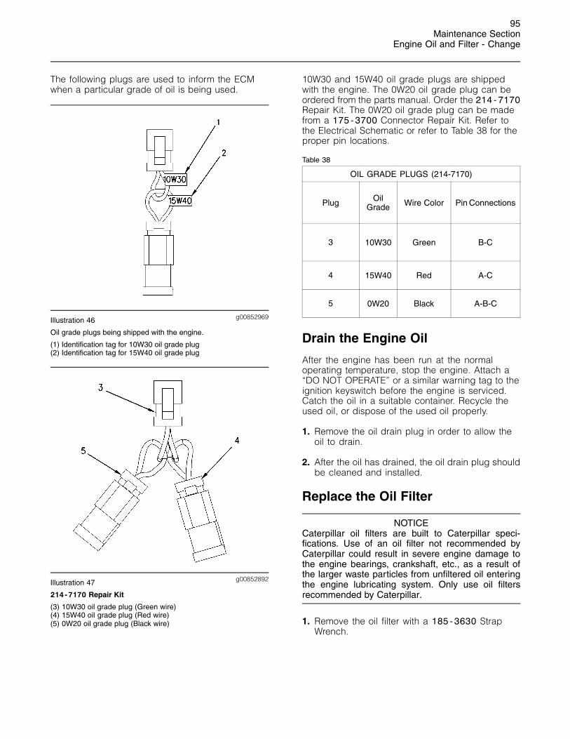
95Maintenance Section
Engine Oil and Filter - Change
The following plugs are used to inform the ECMwhen a particular grade of oil is being used.
g00852969Illustration 46
Oil grade plugs being shipped with the engine.
(1) Identification tag for 10W30 oil grade plug(2) Identification tag for 15W40 oil grade plug
g00852892Illustration 47
214-7170 Repair Kit
(3) 10W30 oil grade plug (Green wire)(4) 15W40 oil grade plug (Red wire)(5) 0W20 oil grade plug (Black wire)
10W30 and 15W40 oil grade plugs are shippedwith the engine. The 0W20 oil grade plug can beordered from the parts manual. Order the 214-7170Repair Kit. The 0W20 oil grade plug can be madefrom a 175-3700 Connector Repair Kit. Refer tothe Electrical Schematic or refer to Table 38 for theproper pin locations.
Table 38
OIL GRADE PLUGS (214-7170)
Plug OilGrade Wire Color Pin Connections
3 10W30 Green B-C
4 15W40 Red A-C
5 0W20 Black A-B-C
Drain the Engine Oil
After the engine has been run at the normaloperating temperature, stop the engine. Attach a“DO NOT OPERATE” or a similar warning tag to theignition keyswitch before the engine is serviced.Catch the oil in a suitable container. Recycle theused oil, or dispose of the used oil properly.
1. Remove the oil drain plug in order to allow theoil to drain.
2. After the oil has drained, the oil drain plug shouldbe cleaned and installed.
Replace the Oil Filter
NOTICECaterpillar oil filters are built to Caterpillar speci-fications. Use of an oil filter not recommended byCaterpillar could result in severe engine damage tothe engine bearings, crankshaft, etc., as a result ofthe larger waste particles from unfiltered oil enteringthe engine lubricating system. Only use oil filtersrecommended by Caterpillar.
1. Remove the oil filter with a 185-3630 StrapWrench.

96Maintenance SectionEngine Oil and Filter - Change
g00588944Illustration 48
Element with debris
2. Cut the oil filter open with a 175-7546 Oil FilterCutter . Break apart the pleats and inspect theoil filter for metal debris. An excessive amount ofmetal debris in the oil filter may indicate earlywear or a pending failure.
Use a magnet to differentiate between theferrous metals and the nonferrous metals thatare found in the oil filter element. Ferrous metalsmay indicate wear on the steel and cast ironparts of the engine.
Nonferrous metals may indicate wear on thealuminum parts, brass parts or bronze parts ofthe engine. Parts that may be affected includethe following items: main bearings, rod bearings,turbocharger bearings, and cylinder heads.
Due to normal wear and friction, it is notuncommon to find small amounts of debris in theoil filter. Consult your Caterpillar dealer in orderto arrange for a further analysis if an excessiveamount of debris is found in the oil filter.
g00103713Illustration 49
Typical filter mounting base and filter gasket
3. Clean the sealing surface of the filter mountingbase. Ensure that all of the old oil filter gasketis removed.
4. Apply clean engine oil to the new oil filter gasket.
NOTICEDo not fill the oil filters with oil before installing them.This oil would not be filtered and could be contaminat-ed. Contaminated oil can cause accelerated wear toengine components.
5. Install the oil filter. Tighten the oil filter until theoil filter gasket contacts the base. Tighten the oilfilter by hand according to the instructions thatare shown on the oil filter. Do not overtighten theoil filter.
Fill the Engine Crankcase
1. Remove the oil filler cap. Refer to theOperation and Maintenance Manual, “LubricantSpecifications” topic (Maintenance Section) formore information. Fill the crankcase with theproper amount of oil. Refer to the Operation andMaintenance Manual, “Refill Capacities” topic(Maintenance Section) for more information.
NOTICEIf equipped with an auxiliary oil filter or system, extraoil must be added when filling the crankcase. Followthe OEM or filter manufacturer’s recommendations. Ifthe extra oil is not added, the engine may starve foroil.
NOTICETo help prevent crankshaft or bearing damage, crankengine to fill all filters before starting. Do not crankengine for more than 30 seconds.
2. Start the engine and run the engine at “LOWIDLE” for two minutes. Perform this procedure inorder to ensure that the lubrication system hasoil and that the oil filters are filled. Inspect the oilfilter for oil leaks.
3. Stop the engine and allow the oil to drain backto the sump for a minimum of ten minutes.
4. Remove the oil level gauge in order to check theoil level. Maintain the oil level between the “ADD”and “FULL” marks on the “ENGINE STOPPED”side of the oil level gauge.
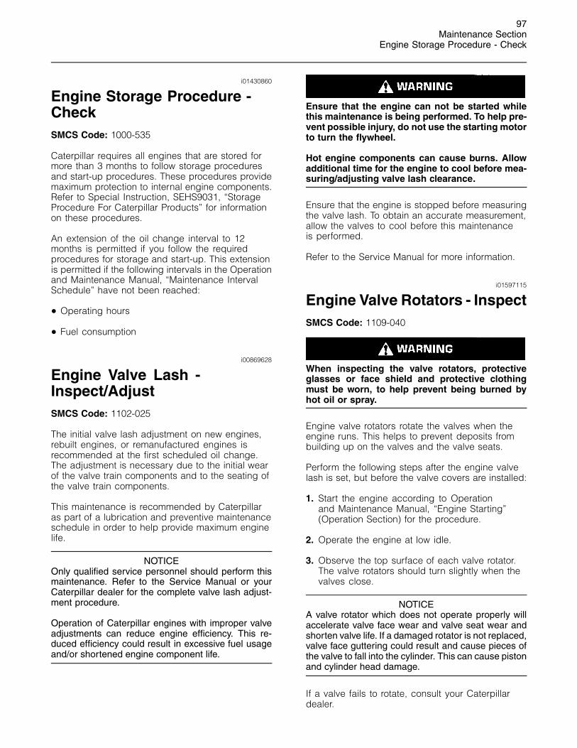
97Maintenance Section
Engine Storage Procedure - Check
i01430860
Engine Storage Procedure -CheckSMCS Code: 1000-535
Caterpillar requires all engines that are stored formore than 3 months to follow storage proceduresand start-up procedures. These procedures providemaximum protection to internal engine components.Refer to Special Instruction, SEHS9031, “StorageProcedure For Caterpillar Products” for informationon these procedures.
An extension of the oil change interval to 12months is permitted if you follow the requiredprocedures for storage and start-up. This extensionis permitted if the following intervals in the Operationand Maintenance Manual, “Maintenance IntervalSchedule” have not been reached:
• Operating hours
• Fuel consumption
i00869628
Engine Valve Lash -Inspect/AdjustSMCS Code: 1102-025
The initial valve lash adjustment on new engines,rebuilt engines, or remanufactured engines isrecommended at the first scheduled oil change.The adjustment is necessary due to the initial wearof the valve train components and to the seating ofthe valve train components.
This maintenance is recommended by Caterpillaras part of a lubrication and preventive maintenanceschedule in order to help provide maximum enginelife.
NOTICEOnly qualified service personnel should perform thismaintenance. Refer to the Service Manual or yourCaterpillar dealer for the complete valve lash adjust-ment procedure.
Operation of Caterpillar engines with improper valveadjustments can reduce engine efficiency. This re-duced efficiency could result in excessive fuel usageand/or shortened engine component life.
Ensure that the engine can not be started whilethis maintenance is being performed. To help pre-vent possible injury, do not use the starting motorto turn the flywheel.
Hot engine components can cause burns. Allowadditional time for the engine to cool before mea-suring/adjusting valve lash clearance.
Ensure that the engine is stopped before measuringthe valve lash. To obtain an accurate measurement,allow the valves to cool before this maintenanceis performed.
Refer to the Service Manual for more information.
i01597115
Engine Valve Rotators - InspectSMCS Code: 1109-040
When inspecting the valve rotators, protectiveglasses or face shield and protective clothingmust be worn, to help prevent being burned byhot oil or spray.
Engine valve rotators rotate the valves when theengine runs. This helps to prevent deposits frombuilding up on the valves and the valve seats.
Perform the following steps after the engine valvelash is set, but before the valve covers are installed:
1. Start the engine according to Operationand Maintenance Manual, “Engine Starting”(Operation Section) for the procedure.
2. Operate the engine at low idle.
3. Observe the top surface of each valve rotator.The valve rotators should turn slightly when thevalves close.
NOTICEA valve rotator which does not operate properly willaccelerate valve face wear and valve seat wear andshorten valve life. If a damaged rotator is not replaced,valve face guttering could result and cause pieces ofthe valve to fall into the cylinder. This can cause pistonand cylinder head damage.
If a valve fails to rotate, consult your Caterpillardealer.

98Maintenance SectionEther Starting Aid Cylinder - Replace
i00805059
Ether Starting Aid Cylinder -Replace(If Equipped)SMCS Code: 1456-510-CD
g00104888Illustration 50
Typical example
1. Loosen the ether cylinder clamp. Unscrew andremove the empty ether cylinder.
2. Remove the used gasket. Install the new gasketthat is provided with each new ether cylinder.
3. Install the new ether cylinder. Hand tighten theether cylinder. Tighten the ether cylinder clampsecurely.
i01423301
Fan Drive Bearing - LubricateSMCS Code: 1359-086-BD
g00746166Illustration 51
Typical location of the grease fitting that is for the fan drive bearing
The pulley is shown with the belt guards removed
Lubricate the grease fitting that is on the fan drivebearing with Bearing Lubricant or the equivalent.
Inspect the fan drive pulley assembly for wear or fordamage. If the shaft is loose, an inspection of theinternal components should be performed. Refer tothe Service Manual for additional information.
i01091827
Fuel System - PrimeSMCS Code: 1258-548
Fuel leaked or spilled onto hot surfaces or elec-trical components can cause a fire. To help pre-vent possible injury, turn the start switch off whenchanging fuel filters or water separator elements.Clean up fuel spills immediately.
NOTICEDo not allow dirt to enter the fuel system. Thoroughlyclean the area around a fuel system component thatwill be disconnected. Fit a suitable cover over any dis-connected fuel system components.
Prime the fuel system in order to fill the fuel filter.Prime the fuel system in order to purge trappedair. The fuel system should be primed under thefollowing conditions:
• Running out of fuel
• Storage
• Replacement of the fuel filter
Engines that are Equipped with aFuel Priming Pump
NOTICEDo not loosen the fuel lines at the fuel manifold. Thefittings may be damaged and/or a loss of priming pres-sure may occur when the fuel lines are loosened.
1. Open the fuel priming pump and operate thefuel priming pump until a strong pressure is felt.This procedure will require considerable strokes.Lock the fuel priming pump.
NOTICEDo not crank the engine continuously for more than30 seconds. Allow the starting motor to cool for twominutes before cranking the engine again.
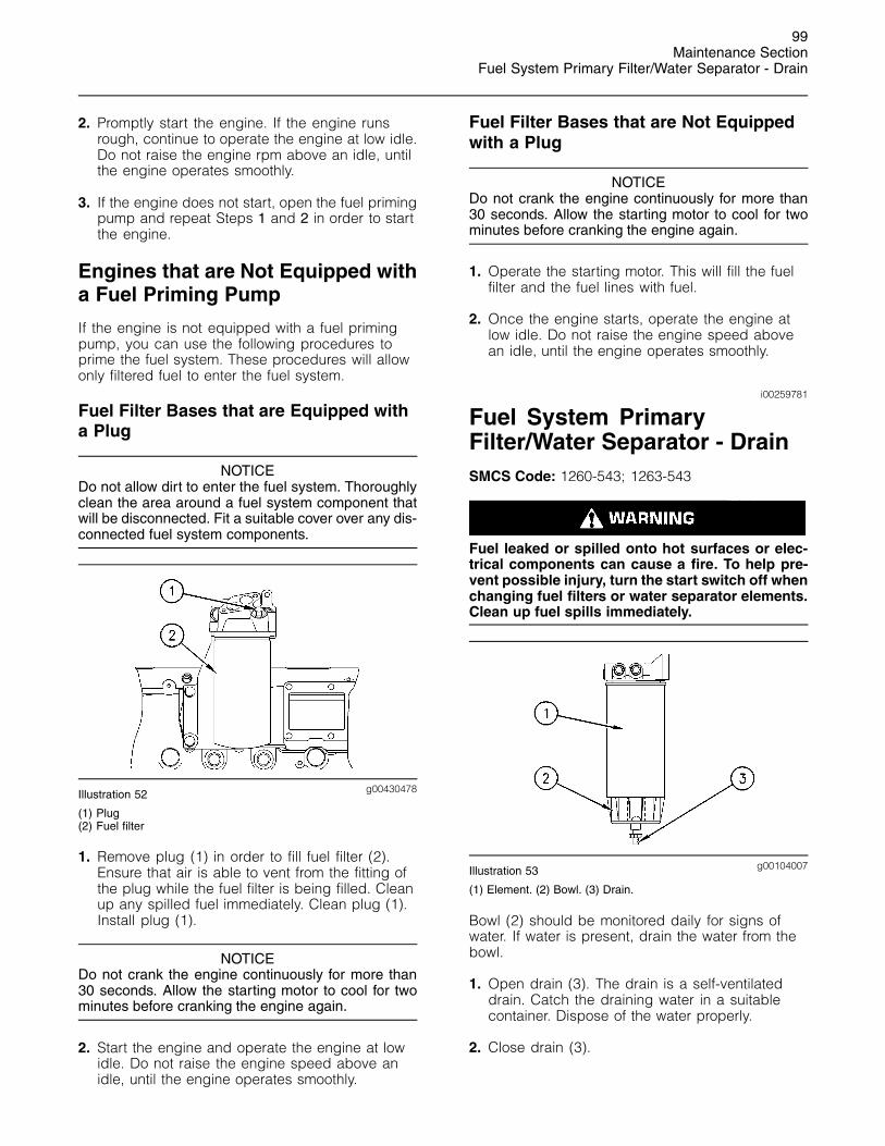
99Maintenance Section
Fuel System Primary Filter/Water Separator - Drain
2. Promptly start the engine. If the engine runsrough, continue to operate the engine at low idle.Do not raise the engine rpm above an idle, untilthe engine operates smoothly.
3. If the engine does not start, open the fuel primingpump and repeat Steps 1 and 2 in order to startthe engine.
Engines that are Not Equipped witha Fuel Priming Pump
If the engine is not equipped with a fuel primingpump, you can use the following procedures toprime the fuel system. These procedures will allowonly filtered fuel to enter the fuel system.
Fuel Filter Bases that are Equipped witha Plug
NOTICEDo not allow dirt to enter the fuel system. Thoroughlyclean the area around a fuel system component thatwill be disconnected. Fit a suitable cover over any dis-connected fuel system components.
g00430478Illustration 52
(1) Plug(2) Fuel filter
1. Remove plug (1) in order to fill fuel filter (2).Ensure that air is able to vent from the fitting ofthe plug while the fuel filter is being filled. Cleanup any spilled fuel immediately. Clean plug (1).Install plug (1).
NOTICEDo not crank the engine continuously for more than30 seconds. Allow the starting motor to cool for twominutes before cranking the engine again.
2. Start the engine and operate the engine at lowidle. Do not raise the engine speed above anidle, until the engine operates smoothly.
Fuel Filter Bases that are Not Equippedwith a Plug
NOTICEDo not crank the engine continuously for more than30 seconds. Allow the starting motor to cool for twominutes before cranking the engine again.
1. Operate the starting motor. This will fill the fuelfilter and the fuel lines with fuel.
2. Once the engine starts, operate the engine atlow idle. Do not raise the engine speed abovean idle, until the engine operates smoothly.
i00259781
Fuel System PrimaryFilter/Water Separator - DrainSMCS Code: 1260-543; 1263-543
Fuel leaked or spilled onto hot surfaces or elec-trical components can cause a fire. To help pre-vent possible injury, turn the start switch off whenchanging fuel filters or water separator elements.Clean up fuel spills immediately.
g00104007Illustration 53
(1) Element. (2) Bowl. (3) Drain.
Bowl (2) should be monitored daily for signs ofwater. If water is present, drain the water from thebowl.
1. Open drain (3). The drain is a self-ventilateddrain. Catch the draining water in a suitablecontainer. Dispose of the water properly.
2. Close drain (3).

100Maintenance SectionFuel System Primary Filter/Water Separator Element - Replace
NOTICEThe water separator is under suction during normalengine operation. Ensure that the drain valve is tight-ened securely to help prevent air from entering the fuelsystem.
i01488870
Fuel System PrimaryFilter/Water Separator Element- ReplaceSMCS Code: 1260-510-FQ; 1263-510-FQ
Water in the fuel can cause the engine to run rough.Water in the fuel may cause a electronic unit injectorto fail. If the fuel has been contaminated with water,the element should be changed before the regularlyscheduled interval.
The primary filter/water separator also providesfiltration in order to help extend the life of thesecondary fuel filter. The element should bechanged regularly. If a vacuum gauge is installed,the primary filter/water separator should be changedat 50 to 70 kPa (15 to 20 inches hg).
Replace the Element
Fuel leaked or spilled onto hot surfaces or elec-trical components can cause a fire. To help pre-vent possible injury, turn the start switch off whenchanging fuel filters or water separator elements.Clean up fuel spills immediately.
Note: A 10 to 15 micron absolute high efficiencyfuel filter is required for Caterpillar Electronic UnitInjectors. Caterpillar High Efficiency Fuel Filtersmeet these requirements. Consult your Caterpillardealer for the proper part number.
1. Close the main fuel supply valve.
g00104012Illustration 54
(1) Element. (2) Bowl. (3) Drain.
2. Remove element (1) from the element mountingbase while bowl (2) is attached.
NOTICEDo not allow dirt to enter the fuel system. Thoroughlyclean the area around a fuel system component thatwill be disconnected. Fit a suitable cover over any dis-connected fuel system components.
NOTICEUse a suitable container to catch any fuel that mightspill. Clean up any spilled fuel immediately.
3. Dispose of the fuel in the fuel filter element.Remove bowl (2) from element (1). The bowl isreusable. Do not discard the bowl. Dispose ofthe used element.
4. Remove the O-ring from the gland of the bowl.Clean the following components:
• Bowl
• O-ring
• Mounting base
Inspect the O-ring for damage and fordeterioration. Replace the O-ring, if necessary.
5. Lubricate the O-ring with clean diesel fuel.
6. Install bowl (2) on a new element. Tighten thebowl by hand. Do not use tools in order to tightenthe bowl.

101Maintenance Section
Fuel System Secondary Filter - Replace
NOTICEThe primary filter/water separator may be prefilled withfuel to avoid rough running/stalling of the engine dueto air. Do not fill the secondary filter with fuel beforeinstallation. The fuel would not be filtered and couldbe contaminated. Contaminated fuel will cause accel-erated wear to fuel system parts.
7. Lubricate the top seal of element (1) with cleandiesel fuel. The element may be filled with fuel atthis time. Install the new element on the mountingbase. Tighten the element by hand.
NOTICEThe water separator is under suction during normalengine operation. Ensure that the vent plug is tight-ened securely to help prevent air from entering the fu-el system.
8. Open the main fuel supply valve.
9. Start the engine and check for leaks. Run theengine for one minute. Stop the engine andcheck for leaks again.
Detection of leaks is difficult while the engineis running. The primary filter/water separator isunder suction. A leak will allow air to enter thefuel. The air in the fuel can cause low powerdue to aeration of the fuel. If air enters the fuel,check the components for overtightening orunder tightening.
i01503750
Fuel System Secondary Filter -ReplaceSMCS Code: 1261-510-SE
Fuel leaked or spilled onto hot surfaces or elec-trical components can cause a fire. To help pre-vent possible injury, turn the start switch off whenchanging fuel filters or water separator elements.Clean up fuel spills immediately.
NOTICEDo not allow dirt to enter the fuel system. Thoroughlyclean the area around a fuel system component thatwill be disconnected. Fit a suitable cover over any dis-connected fuel system components.
NOTICEUse a suitable container to catch any fuel that mightspill. Clean up any spilled fuel immediately.
1. Stop the engine. Turn the ignition switch to theOFF position or disconnect the battery. Referto the Operation and Maintenance Manual,“Battery or Battery Cable - Disconnect” topic(Maintenance Section) for more information. Shutoff the fuel supply valve (if equipped).
2. Remove the used fuel filter and discard the usedfuel filter.
3. Clean the gasket sealing surface of the fuelfilter base. Ensure that all of the old gasket isremoved.
4. Apply clean diesel fuel to the new fuel filtergasket.
NOTICEDo not fill the secondary fuel filter with fuel before in-stalling. The fuel would not be filtered and could becontaminated. Contaminated fuel will cause acceler-ated wear to fuel system parts.
NOTICEIn order to maximize fuel system life and prevent pre-mature wear out from abrasive particles in the fuel,a two micron absolute high efficiency fuel filter is re-quired for all Caterpillar Hydraulic Electronic Unit In-jectors. Caterpillar High Efficiency Fuel Filters meetthese requirements. Consult your Caterpillar dealer forthe proper part numbers.
5. Install the new fuel filter. Spin the fuel filter ontothe fuel filter base until the gasket contacts thebase. Use the rotation index marks on the filtersas a guide for proper tightening. Tighten thefilter for an additional one turn (360 degrees) byhand. Do not overtighten the filter.
6. Open the fuel supply valve. Prime the fuel system.Refer to the Operation and Maintenance Manual,“Fuel System - Prime” topic (MaintenanceSection) for more information. Start the engineand inspect the fuel system for leaks.
NOTICEDo not crank the engine continuously for more than30 seconds. Allow the starting motor to cool for twominutes before cranking the engine again.

102Maintenance SectionFuel Tank Water and Sediment - Drain
Note: There should be enough residual fuel in thecylinder head in order to start the engine. If theengine stops after starting, do not crank the enginefor more than 30 seconds. Then allow the startingmotor to cool for two minutes. Repeat this procedureuntil the engine starts and the engine operates.
i00073301
Fuel Tank Water and Sediment- DrainSMCS Code: 1273-543-M&S
Fuel Tank
Fuel quality is critical to the performance and tothe service life of the engine. Water in the fuel cancause excessive fuel system wear. Condensationoccurs during the heating and cooling of fuel. Thecondensation occurs as the fuel passes throughthe fuel system and the fuel returns to the fuel tank.This causes water to accumulate in fuel tanks.Draining the fuel tank regularly and obtaining fuelfrom reliable sources can help to eliminate waterin the fuel.
Drain the Water and the Sediment
Fuel tanks should contain some provision fordraining water and draining sediment from thebottom of the fuel tanks.
Open the drain valve on the bottom of the fuel tankin order to drain the water and the sediment. Closethe drain valve.
Check the fuel daily. Drain the water and sedimentfrom the fuel tank after operating the engine or drainthe water and sediment from the fuel tank after thefuel tank has been filled. Allow five to ten minutesbefore performing this procedure.
Fill the fuel tank after operating the engine inorder to drive out moist air. This will help preventcondensation. Do not fill the tank to the top. Thefuel expands as the fuel gets warm. The tank mayoverflow.
Some fuel tanks use supply pipes that allow waterand sediment to settle below the end of the fuelsupply pipe. Some fuel tanks use supply lines thattake fuel directly from the bottom of the tank. Ifthe engine is equipped with this system, regularmaintenance of the fuel system filter is important.
Fuel Storage Tanks
Drain the water and the sediment from the fuelstorage tank during the following conditions:
• Weekly
• Oil change
• Refill of the tank
This will help prevent water or sediment from beingpumped from the storage tank into the engine fueltank.
If a bulk storage tank has been refilled or movedrecently, allow adequate time for the sediment tosettle before filling the engine fuel tank. Internalbaffles in the bulk storage tank will also help trapsediment. Filtering fuel that is pumped from thestorage tank helps to ensure the quality of the fuel.When possible, water separators should be used.
i00907072
Hoses and Clamps -Inspect/ReplaceSMCS Code: 7554-040; 7554-510
Inspect all hoses for leaks that are caused by thefollowing conditions:
• Cracking
• Softness
• Loose clamps
Replace hoses that are cracked or soft. Tighten anyloose clamps.
NOTICEDo not bend or strike high pressure lines. Do not in-stall bent or damaged lines, tubes or hoses. Repairany loose or damaged fuel and oil lines, tubes andhoses. Leaks can cause fires. Inspect all lines, tubesand hoses carefully. Tighten all connections to the rec-ommended torque.
Check for the following conditions:
• End fittings that are damaged or leaking
• Outer covering that is chafed or cut
• Exposed wire that is used for reinforcement
• Outer covering that is ballooning locally

103Maintenance Section
Jacket Water Heater - Check
• Flexible part of the hose that is kinked or crushed
• Armoring that is embedded in the outer covering
A constant torque hose clamp can be used inplace of any standard hose clamp. Ensure that theconstant torque hose clamp is the same size asthe standard clamp.
Due to extreme temperature changes, the hosewill heat set. Heat setting causes hose clamps toloosen. This can result in leaks. A constant torquehose clamp will help to prevent loose hose clamps.
Each installation application can be different. Thedifferences depend on the following factors:
• Type of hose
• Type of fitting material
• Anticipated expansion and contraction of thehose
• Anticipated expansion and contraction of thefittings
Replace the Hoses and the Clamps
Pressurized System: Hot coolant can cause seri-ous burns. To open the cooling system filler cap,stop the engine and wait until the cooling systemcomponents are cool. Loosen the cooling systempressure cap slowly in order to relieve the pres-sure.
1. Stop the engine. Allow the engine to cool.
2. Loosen the cooling system filler cap slowlyin order to relieve any pressure. Remove thecooling system filler cap.
Note: Drain the coolant into a suitable, cleancontainer. The coolant can be reused.
3. Drain the coolant from the cooling system toa level that is below the hose that is beingreplaced.
4. Remove the hose clamps.
5. Disconnect the old hose.
6. Replace the old hose with a new hose.
Note: For torques on hose clamps, see thisOperation and Maintenance Manual, “TorqueSpecifications” (Maintenance Section).
7. Install the hose clamps with a torque wrench.
Note: For the proper coolant to use, see thisOperation and Maintenance Manual, “CoolantRecommendations” (Maintenance Section).
8. Refill the cooling system.
9. Clean the cooling system filler cap. Inspect thecooling system filler cap’s gaskets. Replacethe cooling system filler cap if the gaskets aredamaged. Install the cooling system filler cap.
10. Start the engine. Inspect the cooling system forleaks.
i01042517
Jacket Water Heater - CheckSMCS Code: 1383-535
Jacket water heaters help to improve startability inambient temperatures that are below 21 �C (70 �F).All installations that require automatic startingshould have jacket water heaters.
Check the operation of the jacket water heater. Foran ambient temperature of 0 �C (32 �F), the heatershould maintain the jacket water temperature atapproximately 32 �C (90 �F).
i01452713
Overhaul ConsiderationsSMCS Code: 7595-043
Reduced hours of operation at full load will resultin a lower average power demand. A decreasedaverage power demand should increase both theengine service life and the overhaul interval.
The need for an overhaul is generally indicated byincreased fuel consumption and by reduced power.
The following factors are important when a decisionis being made on the proper time for an engineoverhaul:
• The need for preventive maintenance
• The quality of the fuel that is being used
• The operating conditions
• The results of the S·O·S analysis

104Maintenance SectionOverhaul Considerations
Oil Consumption as an OverhaulIndicator
Oil consumption, fuel consumption, andmaintenance information can be used to estimatethe total operating cost for your Caterpillar engine.Oil consumption can also be used to estimatethe required capacity of a makeup oil tank that issuitable for the maintenance intervals.
Oil consumption is in proportion to the percentageof the rated engine load. As the percentage of theengine load is increased, the amount of oil that isconsumed per hour also increases.
The oil consumption rate (brake specific oilconsumption) is measured in grams per kW/h(lb per bhp). The brake specific oil consumption(BSOC) depends on the engine load. Consult yourCaterpillar dealer for assistance in determining thetypical oil consumption rate for your engine.
When an engine’s oil consumption has risen tothree times the original oil consumption rate dueto normal wear, an engine overhaul should bescheduled. There may be a corresponding increasein blowby and a slight increase in fuel consumption.
Overhaul Options
Before Failure Overhaul
A planned overhaul before failure may be the bestvalue for the following reasons:
• Costly unplanned downtime can be avoided.
• Many original parts can be reused according tothe standards for reusable parts.
• The engine’s service life can be extended withoutthe risk of a major catastrophe due to enginefailure.
• The best cost/value relationship per hour ofextended life can be attained.
After Failure Overhaul
If a major engine failure occurs and the enginemust be removed, many options are available. Anoverhaul should be performed if the engine blockor the crankshaft needs to be repaired.
If the engine block is repairable and/or thecrankshaft is repairable, the overhaul cost shouldbe between 40 percent and 50 percent of the costof a new engine with a similar exchange core.
This lower cost can be attributed to three aspects:
• Specially designed Caterpillar engine features
• Caterpillar dealer exchange components
• Caterpillar Inc. remanufactured exchangecomponents
Overhaul Recommendation
To minimize downtime, Caterpillar Inc. recommendsa scheduled engine overhaul by your Caterpillardealer before the engine fails. This will provide youwith the best cost/value relationship.
Note: Overhaul programs vary according to theengine application and according to the dealerthat performs the overhaul. Consult your Caterpillardealer for specific information about the availableoverhaul programs and about overhaul services forextending the engine life.
If an overhaul is performed without overhaul servicefrom your Caterpillar dealer, be aware of thefollowing maintenance recommendations.
Rebuild or Exchange
Cylinder Head Assembly, Cylinder Packs, OilPump, and Fuel Transfer Pump
These components should be inspected accordingto the instructions that are found in variousCaterpillar reusability publications. The SpecialPublication, SEBF8029 lists the reusabilitypublications that are needed for inspecting theengine parts.
If the parts comply with the established inspectionspecifications that are expressed in the reusableparts guideline, the parts should be reused.
Parts that are not within the established inspectionspecifications should be dealt with in one of thefollowing manners:
• Salvaging
• Repairing
• Replacing
Using out-of-spec parts can result in the followingproblems:
• Unscheduled downtime
• Costly repairs
• Damage to other engine parts
• Reduced engine efficiency

105Maintenance Section
Overhaul Considerations
• Increased fuel consumption
Reduced engine efficiency and increased fuelconsumption translates into higher operating costs.Therefore, Caterpillar Inc. recommends repairingout-of-spec parts or replacing out-of-spec parts.
Inspection and/or Replacement
Crankshaft Bearings, Valve Rotators, andCrankshaft Seals
The following components may not last until thesecond overhaul.
• Thrust bearings
• Main bearings
• Rod bearings
• Valve rotators
• Crankshaft seals
Caterpillar Inc. recommends the installation of newparts at each overhaul period.
Inspect these parts while the engine is disassembledfor an overhaul.
Inspect the crankshaft for any of the followingconditions:
• Deflection
• Damage to the journals
• Bearing material that has seized to the journals
Check the journal taper and the profile of thecrankshaft journals. Check these components byinterpreting the wear patterns on the followingcomponents:
• Rod bearing
• Main bearings
Inspect the camshaft for damage to the journalsand to the lobes.
Note: If the camshaft is removed for any reason, usethe magnetic particle inspection process to checkfor cracks in the camshaft.
Inspect the following components for signs of wearor for signs of scuffing:
• Camshaft bearings
• Camshaft followers
Caterpillar Inc. recommends replacing thecrankshaft vibration damper.
Oil Cooler Core
During an overhaul, Caterpillar Inc. recommendsthe removal of the oil cooler core. Clean the oilcooler core. Then, pressure test the oil cooler core.
NOTICEDo not use caustic cleaners to clean the core.
Caustic cleaners can attack the internal metals of thecore and cause leakage.
Note: Use this cleaning procedure to clean the oilcooler core.
1. Remove the oil cooler core.
2. Remove any debris from the oil cooler core. Toremove debris from the oil cooler core, turn theoil cooler core onto one end.
3. Flush the oil cooler core internally with cleaner inorder to loosen foreign substances. This will alsohelp to remove oil from the oil cooler core.
Note: Caterpillar Inc. recommends the use ofHydrosolv Liquid Cleaners. Table 39 lists theHydrosolv Liquid Cleaners that are available fromyour Caterpillar dealer.
Table 39
HydrosolvLiquid Cleaners
PartNumber Description Size
1U-8812 4 L (1 US gallon)
1U-5490 19 L (5 US gallon)
8T-7570
Hydrosolv4165
208 L (55 US gallon)
1U-8804 4 L (1 US gallon)
1U-5492 19 L (5 US gallon)
8T-5571
Hydrosolv100
208 L (55 US gallon)
4. Use steam to clean the oil cooler core. Thisremoves any remaining residue from the cleaner.Flush the fins of the oil cooler core. Remove anyother trapped debris.
5. Wash the oil cooler core with hot, soapy water.Rinse the oil cooler core thoroughly with cleanwater.

106Maintenance SectionPower Take-Off Clutch - Check/Adjust/Lubricate
Personal injury can result from air pressure.
Personal injury can result without following prop-er procedure. When using pressure air, wear a pro-tective face shield and protective clothing.
Maximum air pressure at the nozzle must be lessthan 205 kPa (30 psi) for cleaning purposes.
6. Dry the oil cooler core with compressed air.Direct the air in the reverse direction of thenormal flow.
7. Inspect the components in order to ensurecleanliness. The oil cooler core should bepressure tested. Repair the oil cooler core, ifnecessary. Install the oil cooler core.
For more information about cleaning the cores,consult your Caterpillar dealer.
Obtain Coolant Analysis
The concentration of supplemental coolant additive(SCA) should be checked regularly with test kitsor with S·O·S Coolant Analysis (Level 1). Furthercoolant analysis is recommended when the engineis overhauled.
For example, considerable deposits are found in thewater jacket areas on the external cooling system,but the concentrations of coolant additives werecarefully maintained. The coolant water probablycontained minerals that were deposited on theengine over time.
A coolant analysis can be conducted in orderto verify the condition of the water that is beingused in the cooling system. A full water analysiscan be obtained by consulting your local waterutility company or an agricultural agent. Privatelaboratories are also available for water analysis.
Caterpillar Inc. recommends an S·O·S CoolantAnalysis (Level 2).
S·O·S Coolant Analysis (Level 2)
An S·O·S Coolant Analysis (Level 2) is acomprehensive coolant analysis which completelyanalyzes the coolant and the effects on the coolingsystem. An S·O·S Coolant Analysis (Level 2)provides the following information:
• Complete S·O·S Coolant Analysis (Level 1)
• Visual inspection of properties
• Identification of metal corrosion
• Identification of contaminants
• Identification of built up impurities (corrosion andscale)
S·O·S Coolant Analysis (Level 2) provides a report ofthe results of both the analysis and the maintenancerecommendations.
For more information about coolant analysis, seeyour Caterpillar dealer.
i01506009
Power Take-Off Clutch -Check/Adjust/LubricateSMCS Code: 3055-036; 3055-086
NOTICENew power take-offs should have the clutch adjust-ment checked before being placed into service. Theclutch adjustment should be checked again after thefirst ten hours of operation. New clutch plates have a“wear in” period, and the clutch may require severaladjustments until the new plates are “worn in”.
g00781502Illustration 55
(1) Instruction plate(2) Serial number plate
Check the clutch adjustment regularly after“wear in”. Heavy-duty applications which haveengagements that are frequent and relatively longperiods of clutch slippage require more frequentadjustment than light-duty applications. Theoperating torque should be measured in order todetermine if a clutch adjustment is required.
Refer to the OEM information and instruction plate(1) for instructions on lubrication, adjustment, andother recommendations for service. Perform themaintenance that is specified on the instructionplate.

107Maintenance Section
Radiator - Clean
Do not operate the engine with the InstructionPlate cover removed from the clutch. Personalinjury may result.
If the clutch is damaged to the point of burst fail-ure, expelled pieces can cause personal injury toanyone in the immediate area. Proper safeguardsmust be followed to help prevent accidents.
i01604510
Radiator - CleanSMCS Code: 1353-070
Note: Adjust the frequency of cleaning according tothe effects of the operating environment.
Inspect the radiator for these items: damaged fins,corrosion, dirt, grease, insects, leaves, oil, andother debris. Clean the radiator, if necessary.
Personal injury can result from air pressure.
Personal injury can result without following prop-er procedure. When using pressure air, wear a pro-tective face shield and protective clothing.
Maximum air pressure at the nozzle must be lessthan 205 kPa (30 psi) for cleaning purposes.
Pressurized air is the preferred method for removingloose debris. Direct the air in the opposite directionof the fan’s air flow. Hold the nozzle approximately6 mm (0.25 inch) away from the fins. Slowly movethe air nozzle in a direction that is parallel with thetubes. This will remove debris that is between thetubes.
Pressurized water may also be used for cleaning.The maximum water pressure for cleaning purposesmust be less than 275 kPa (40 psi). Use pressurizedwater in order to soften mud. Clean the core fromboth sides.
Use a degreaser and steam for removal of oil andgrease. Clean both sides of the core. Wash the corewith detergent and hot water. Thoroughly rinse thecore with clean water.
After cleaning, start the engine and accelerate theengine to high idle rpm. This will help in the removalof debris and drying of the core. Stop the engine.Use a light bulb behind the core in order to inspectthe core for cleanliness. Repeat the cleaning, ifnecessary.
Inspect the fins for damage. Bent fins may beopened with a “comb”. Inspect these items forgood condition: welds, mounting brackets, air lines,connections, clamps, and seals. Make repairs, ifnecessary.
For more detailed information on cleaning andinspection, refer to Special Publication, SEBD0518,“Know Your Cooling System”.
i00151038
Severe Service Application -CheckSMCS Code: 1000-535
Severe service is an application of an enginethat exceeds current published standards for thatengine. Caterpillar maintains standards for thefollowing engine parameters:
• Performance (power range, speed range, andfuel consumption)
• Fuel quality
• Altitude range
• Maintenance intervals
• Oil selection and maintenance
• Coolant selection and maintenance
• Environmental qualities
• Installation
Refer to the standards for the engine or consult withyour Caterpillar dealer in order to determine if theengine is operating within the defined parameters.
Severe service operation can accelerate componentwear. Engines that operate under severe conditionsmay need more frequent maintenance intervals inorder to ensure maximum reliability and retentionof full service life.
Due to individual applications, it is not possible toidentify all of the factors which can contribute tosevere service operation. Consult your Caterpillardealer for the unique maintenance that is necessaryfor the engine.

108Maintenance SectionStarting Motor - Inspect
The operating environment, improper operatingprocedures and improper maintenance procedurescan be factors which contribute to severe serviceconditions.
Environmental Factors
Ambient temperatures – The engine may beexposed to extended operation in extremelycold environments or hot environments. Valvecomponents can be damaged by carbon buildup ifthe engine is frequently started and stopped in verycold temperatures. Extremely hot inlet air reducesengine performance.
Air Quality – The engine may be exposed toextended operation in an environment that is dirtyor dusty, unless the equipment is cleaned regularly.Mud, dirt and dust can encase components.Maintenance can be very difficult. The buildup cancontain corrosive chemicals.
Buildup – Compounds, elements, corrosivechemicals and salt can damage some components.
Altitude – Problems can arise when the engineis operated at altitudes that are higher than theintended settings for that application. Necessaryadjustments should be made.
Improper Operating Procedures
• Extended operation at low idle
• Frequent hot shutdowns
• Operating at excessive loads
• Operating at excessive speeds
• Operating outside the intended application
Improper Maintenance Procedures
• Extending the maintenance intervals
• Failure to use recommended fuel, lubricants andcoolant/antifreeze
i00651416
Starting Motor - InspectSMCS Code: 1451-040; 1453-040
Caterpillar Inc. recommends a scheduled inspectionof the starting motor. If the starting motor fails, theengine may not start in an emergency situation.
Check the starting motor for proper operation.Check the electrical connections and clean theelectrical connections. Refer to the Service Manualfor more information on the checking procedure andfor specifications or consult your Caterpillar dealerfor assistance.
i01539769
Turbocharger - InspectSMCS Code: 1052-040
Periodic inspection and cleaning is recommendedfor the turbocharger compressor housing (inletside). Any fumes from the crankcase are filteredthrough the air inlet system. Therefore, by-productsfrom oil and from combustion can collect in theturbocharger compressor housing. Over time, thisbuildup can contribute to loss of engine power,increased black smoke and overall loss of engineefficiency.
If the turbocharger fails during engine operation,damage to the turbocharger compressor wheeland/or to the engine may occur. Damage tothe turbocharger compressor wheel can causeadditional damage to the pistons, the valves, andthe cylinder head.
NOTICETurbocharger bearing failures can cause large quan-tities of oil to enter the air inlet and exhaust systems.Loss of engine lubricant can result in serious enginedamage.
Minor leakage of a turbocharger housing under ex-tended low idle operation should not cause problemsas long as a turbocharger bearing failure has not oc-curred.
When a turbocharger bearing failure is accompaniedby a significant engine performance loss (exhaustsmoke or engine rpm up at no load), do not continueengine operation until the turbocharger is repaired orreplaced.
An inspection of the turbocharger can minimizeunscheduled downtime. An inspection of theturbocharger can also reduce the chance forpotential damage to other engine parts.
Note: Turbocharger components require precisionclearances. The turbocharger cartridge mustbe balanced due to high rpm. Severe ServiceApplications can accelerate component wear.Severe Service Applications require more frequentinspections of the cartridge.

109Maintenance Section
Walk-Around Inspection
Removal and Installation
For options regarding the removal, installation,repair and replacement, consult your Caterpillardealer. Refer to the Service Manual for this enginefor the procedure and specifications.
Cleaning and Inspecting
1. Remove the exhaust outlet piping and removethe air inlet piping from the turbocharger. Visuallyinspect the piping for the presence of oil. Cleanthe interior of the pipes in order to prevent dirtfrom entering during reassembly.
2. Turn the compressor wheel and the turbinewheel by hand. The assembly should turn freely.Inspect the compressor wheel and the turbinewheel for contact with the turbocharger housing.There should not be any visible signs of contactbetween the turbine wheel or compressorwheel and the turbocharger housing. If there isany indication of contact between the rotatingturbine wheel or the compressor wheel and theturbocharger housing, the turbocharger must bereconditioned.
3. Check the compressor wheel for cleanliness.If only the blade side of the wheel is dirty,dirt and/or moisture is passing through the airfiltering system. If oil is found only on the backside of the wheel, there is a possibility of a failedturbocharger oil seal.
The presence of oil may be the result of extendedengine operation at low idle. The presence of oilmay also be the result of a restriction of the linefor the inlet air (plugged air filters), which causesthe turbocharger to slobber.
4. Use a dial indicator to check the end clearanceon the shaft. If the measured end play is greaterthan the Service Manual specifications, theturbocharger should be repaired or replaced.An end play measurement that is less than theminimum Service Manual specifications couldindicate carbon buildup on the turbine wheel.The turbocharger should be disassembled forcleaning and for inspection if the measured endplay is less than the minimum Service Manualspecifications.
5. Inspect the bore of the turbine housing forcorrosion.
6. Clean the turbocharger housing with standardshop solvents and a soft bristle brush.
7. Fasten the air inlet piping and the exhaust outletpiping to the turbocharger housing.
i01185304
Walk-Around InspectionSMCS Code: 1000-040
Inspect the Engine for Leaks andfor Loose Connections
A walk-around inspection should only take a fewminutes. When the time is taken to perform thesechecks, costly repairs and accidents can beavoided.
For maximum engine service life, make a thoroughinspection of the engine compartment beforestarting the engine. Look for items such as oil leaksor coolant leaks, loose bolts, worn belts, looseconnections and trash buildup. Make repairs, asneeded:
• The guards must be in the proper place. Repairdamaged guards or replace missing guards.
• Wipe all caps and plugs before the engine isserviced in order to reduce the chance of systemcontamination.
NOTICEFor any type of leak (coolant, lube, or fuel) clean up thefluid. If leaking is observed, find the source and correctthe leak. If leaking is suspected, check the fluid levelsmore often than recommended until the leak is foundor fixed, or until the suspicion of a leak is proved to beunwarranted.
NOTICEAccumulated grease and/or oil on an engine or deck isa fire hazard. Remove this debris with steam cleaningor high pressure water.
• Ensure that the cooling lines are properly clampedand that the cooling lines are tight. Check forleaks. Check the condition of all pipes.
• Inspect the water pumps for coolant leaks.
Note: The water pump seal is lubricated by coolantin the cooling system. It is normal for a small amountof leakage to occur as the engine cools down andthe parts contract.
Excessive coolant leakage may indicate the needto replace the water pump seal. For the removal ofwater pumps and the installation of water pumpsand/or seals, refer to the Service Manual for theengine or consult your Caterpillar dealer.

110Maintenance SectionWater Pump - Inspect
• Inspect the lubrication system for leaks at thefront crankshaft seal, the rear crankshaft seal, theoil pan, the oil filters and the valve cover.
• Inspect the fuel system for leaks. Look for loosefuel line clamps or for loose fuel line tie-wraps.
• Inspect the piping for the air inlet system and theelbows for cracks and for loose clamps. Ensurethat hoses and tubes are not contacting otherhoses, tubes, wiring harnesses, etc.
• Inspect the alternator belt and the accessorydrive belts for cracks, breaks or other damage.
Belts for multiple groove pulleys must be replacedas matched sets. If only one belt is replaced, thebelt will carry more load than the belts that arenot replaced. The older belts are stretched. Theadditional load on the new belt could cause thebelt to break.
• Drain the water and the sediment from fuel tankson a daily basis in order to ensure that only cleanfuel enters the fuel system.
• Inspect the wiring and the wiring harnesses forloose connections and for worn wires or frayedwires.
• Inspect the ground strap for a good connectionand for good condition.
• Inspect the ECM to the cylinder head groundstrap for a good connection and for goodcondition.
• Disconnect any battery chargers that are notprotected against the current drain of the startingmotor. Check the condition and the electrolytelevel of the batteries, unless the engine isequipped with a maintenance free battery.
• Check the condition of the gauges. Replace anygauges that are cracked. Replace any gauge thatcan not be calibrated.
i01057943
Water Pump - InspectSMCS Code: 1361-040; 1361
A failed water pump might cause severe engineoverheating problems that could result in thefollowing conditions:
• Cracks in the cylinder head
• A piston seizure
• Other potential damage to the engine
Visually inspect the water pump for leaks. If anyleaking is observed, replace the water pumpseal or the water pump assembly. Refer to theService Manual for the disassembly and assemblyprocedure.
Note: Refer to the Service Manual or consult yourCaterpillar dealer if any repair is needed or anyreplacement is needed.
111Warranty Section
Warranty Information
Warranty Section
Warranty Information
i01087950
Emissions WarrantyInformationSMCS Code: 1000
This engine may be certified to comply withexhaust emission standards and gaseous emissionstandards that are prescribed by law at the timeof manufacture, and this engine may be coveredby an Emissions Warranty. A detailed explanationof the Emissions Warranty that is applicable toemissions certified engines is found in Supplement,SEBU6981, “Federal Emissions Control WarrantyInformation”. Consult your authorized Caterpillardealer to determine if your engine is emissionscertified and if your engine is subject to anEmissions Warranty.
112Reference Information SectionEngine Ratings
Reference InformationSection
Engine Ratings
i00727327
Engine Rating ConditionsSMCS Code: 1000
All engine ratings are in compliance with thefollowing standard ambient air conditions of “SAEJ1349”:
• 99 kPa (29.3 inches of Hg)
• 30 percent relative humidity
• A temperature of 25 �C (77 �F)
Ratings relate to the standard conditions of“ISO8665”, of “ISO3046/1”, of “DIN6271”, and of“BS5514”.
The engine ratings are based on the following fuelspecifications:
• Low heat value (LHV) of the fuel of 42 780 kJ/kg(18,390 Btu/lb) at 29 �C (84 �F)
• Gravity (API) of 35 degrees at 15 �C (60 �F)
• Specific gravity of .849 at 15 �C (60 �F)
• Density of 850 kg/m3 (7.085 lb/US gal)
The engine ratings are gross output ratings.
Gross Output Ratings – The total output capabilityof the engine that is equipped with standardaccessories.
Standard accessories include the followingcomponents:
• Oil pumps
• Fuel pumps
• Water pumps
Subtract the power that is required to drive auxiliarycomponents from the gross output. This will producethe net power that is available for the external load(flywheel).
i00819749
Engine Rating DefinitionsSMCS Code: 1000
It is important to know the use of the engine sothat the rating will match the operating profile. Theproper rating selection is also important so that thecustomer’s perception of price and value is realized.
In selecting a rating for a specific application, themost important consideration is the time that isspent at full throttle. These rating definitions identifythe percent of time at full throttle. The definitionsalso identify the corresponding times below ratedrpm.
Note: The examples of the applications are onlyfor reference. For an exact determination of theappropriate rating, follow the OEM specifications orconsult your Caterpillar dealer.
A Rating – This rating is used for heavy-dutyapplications that are operated at rated load and atrated rpm up to 100 percent. This rating is usedfor engines that operate without interruption of loadcycling. Typical applications include the followingexamples: pipeline pumping and ventilation.
B Rating – This rating is used when power and/orrpm are cyclic. The engine should be run at full load.The engine should not exceed 80 percent of theduty cycle. Typical applications include the followingexamples: irrigation, operation where normal pumpdemand is 85 percent of the engine rating, oilpumping/drilling, field mechanical pumping/drilling,and stationary/plant air compressors.
C Rating – This rating is used when power and/orrpm are cyclic. The horsepower and the rpm of theengine can be utilized continuously for one hour.This is followed by one hour of operation at the Arating or below the A rating. The engine shouldbe run at full load. The engine should not exceed50 percent of the duty cycle. Typical applicationsinclude the following examples: agricultural tractors,harvesters and combines, off-highway trucks, firepumps, blast hole drills, rock curshers, woodchippers with high torque rise, and oil field hoisting.
D Rating – This rating is used when rated poweris required for periodic overloads. The maximumhorsepower and the rpm of the engine can beutilized continuously for a maximum of 30 minutes.This is followed by one hour of operation at the Crating. The engine should be run at full load. Theengine should not exceed 10 percent of the dutycycle. Typical applications include the followingexamples: offshore cranes, runway snow blowers,water well drills, portable air compressors, and firepump certification power.

113Reference Information Section
Engine Ratings
E Rating – This rating is used when rated poweris required for a short time for initial starting orfor sudden overload. The rating is also used foremergency service when standard power is notavailable. The horsepower and the rpm of theengine can be utilized continuously for a maximumof 15 minutes. This is followed by one hour ofoperation at the C rating or by the duration of theemergency. The engine should be run at full load.The engine should not exceed 5 percent of the dutycycle. Typical applications include the followingexamples: standby centrifugal water pumps, oilfield well servicing, crash trucks, portable aircompressors, and gas turbine starting motors.
NOTICEOperating engines above the rating definitions can re-sult in shorter service life before overhaul.

114Reference Information SectionCustomer Service
Customer Service
i01706971
Customer AssistanceSMCS Code: 1000
USA and Canada
When a problem arises concerning the operation ofan engine or concerning the service of an engine,the problem will normally be managed by the dealerin your area.
Your satisfaction is a primary concern to Caterpillarand to Caterpillar dealers. If you have a problemthat has not been handled to your completesatisfaction, follow these steps:
1. Discuss your problem with a manager from thedealership.
2. If your problem cannot be resolved at the dealerlevel without additional assistance, use thephone number that is listed below to talk with aField Service Coordinator:
1-800-447-4986
The normal hours are from 8:00 to 4:30 Mondaythrough Friday Central Standard Time.
3. If your needs have not been met still, submit thematter in writing to the following address:
Caterpillar Inc.Manager, Customer Service, Engine DivisionMossville Bldg ACP.O. Box 610Mossville, Illinois 61552-0610
Please keep in mind: probably, your problem willultimately be solved at the dealership, using thedealership’s facilities, equipment, and personnel.Therefore, follow the steps in sequence when aproblem is experienced.
Outside of the USA and of Canada
If a problem arises outside the USA and outsideCanada, and if the problem cannot be resolved atthe dealer level, consult the appropriate Caterpillaroffice.
Latin America, Mexico, CarribeanCaterpillar Americas Co.701 Waterford Way, Suite 200Miami, FL 33126-4670USAPhone: 305-476-6800Fax: 305-476-6801
Europe, Africa, and Middle EastCaterpillar Overseas S.A.76 Route de FrontenexP.O. Box 6000CH-1211 Geneva 6SwitzerlandPhone: 22-849-4444Fax: 22-849-4544
Far EastCaterpillar Asia Pte. Ltd.7 Tractor RoadJurong, Singapore 627968Republic of SingaporePhone: 65-662-8333Fax: 65-662-8302
ChinaCaterpillar China Ltd.37/F., The Lee Gardens33 Hysan AvenueCauseway BayG.P.O. Box 3069Hong KongPhone: 852-2848-0333Fax: 852-2848-0440
JapanShin Caterpillar Mitsubishi Ltd.SBS Tower10-1, Yoga 4-ChomeSetagaya-Ku, Tokyo 158-8530JapanPhone: 81-3-5717-1150Fax: 81-3-5717-1177
JapanCaterpillar Power Systems, Inc.8F, AIG Aoyama Bldg.2-11-16, Minami-AoyamaMinato-ku, Tokyo 107-0062Phone: 81-3-5786-3803Fax: 81-3-5786-3809
Australia and New ZealandCaterpillar of Australia Ltd.1 Caterpillar DrivePrivate Mail Bag 4Tullamarine, Victoria 3043AustraliaPhone: 03-9953-9333Fax: 03-9335-3366

115Reference Information Section
Customer Service
i01028392
Ordering Replacement PartsSMCS Code: 7567
When replacement parts are required for thisproduct Caterpillar recommends using Caterpillarreplacement parts or parts with equivalent spec-ifications including, but not limited to, physicaldimensions, type, strength and material.
Failure to heed this warning can lead to prema-ture failures, product damage, personal injury ordeath.
Quality Caterpillar replacement parts are availablefrom Caterpillar dealers throughout the world.Caterpillar dealers’ parts inventories are up-to-date.The parts stocks include all of the parts that arenormally needed to protect your Caterpillar engineinvestment.
When you order parts, please specify the followinginformation:
• Part number
• Part name
• Quantity
If there is a question concerning the part number,please provide your dealer with a completedescription of the needed item.
When a Caterpillar engine requires maintenanceand/or repair, provide the dealer with all theinformation that is stamped on the Information Plate.This information is described in this Operation andMaintenance Manual (Product Information Section).
Discuss the problem with the dealer. Inform thedealer about the conditions of the problem andthe nature of the problem. Inform the dealer aboutwhen the problem occurs. This will help the dealerin troubleshooting the problem and solving theproblem faster.

116Reference Information SectionReference Materials
Reference Materials
i01498520
Reference MaterialSMCS Code: 1000
The following literature can be obtained through anyCaterpillar dealer.
Coolants
• Special Publication, SEBD0970, “Coolant andYour Engine”
• Special Publication, PEHP4036, “Data Sheet-Extended Life Coolant”
• Special Publication, SEBD0518, “Know YourCooling System”
• Special Publication, PEEP5027, “Label - ELCRadiator Label”
• Special Publication, PEHP7057, “S·O·S CoolantAnalysis”
Fuels
• Special Publication, SENR9620, “Improving FuelSystem Durability”
• Special Publication, SEBD0717, “Diesel Fuels andYour Engine”
Lubricants
• Special Publication, PEDP7035, “Optimizing OilChange Intervals”
• Special Publication, PEHP8038, “Data Sheet -Caterpillar Diesel Engine Oils (DEO) (CH-4, CG-4,CF-4) (North America and Australia)”
• Special Publication, PEHP7041, “Product DataSheet for Caterpillar Diesel Engine Oils (DEO)”CG-4 engine oils (International markets)
• Special Publication, PEWP3014, “Cat FluidsSelector Dial (International)”
• Special Publication, PEWP9733, “Cat FluidsSelector Dial (North America)”
• Special Publication, NEDG6022, “Data Sheet -Multipurpose Lithium Complex Grease (MPG)”
• Special Publication, PEHP0002, “Data Sheet- Multipurpose Lithium Complex Grease withMolybdenum (MPGM)”
• Special Publication, PEHP0017, “Data Sheet -Special Purpose Grease (SPG) Bearing Lubricant”
• Special Publication, NEHP5621, “How To SelectThe Right Grease For Any Job”
• Special Publication, PEHP6001, “How To Take AGood Oil Sample”
• Special Publication, SEBD0640, “Oil and YourEngine”
• Special Publications, PEDP7036, “S·O·S FluidsAnalysis Cornerstone”
Miscellaneous
• Service Manual, SENR9595, “C-9 IndustrialEngine Service Manual”
• Special Publication, SEBU6251, “CaterpillarCommercial Diesel Engine FluidsRecommendations For Lubricants, DieselFuel, and Coolants”
• Special Publication, PECP6026, “One SafeSource”
• Special Instruction, SMHS7001, “Assembly of FanDrive Pulley Assemblies”
• Special Instruction, SEHS7633, “Battery TestProcedure”
• Special Publication, SEBF8062, “Guideline forReusable Parts - Procedure to Inspect and CleanAir Filters”
• Special Publication, SEBF8029, “Index toGuidelines for Reusable Parts and SalvageOperations”
• Special Publication, PEDP0026, “Power AnalysisReport”
• Special Publication, NEHS0526, “ServiceTechnology Application Guide”
• Special Instruction, SEHS9031, “StorageProcedure for Caterpillar Products”
• Specifications, SENR3130, “Torque SpecificationsModule”
• Special Instruction, SEHS7768, “Use of 6V-2150Starting/Charging Analyzer”

117Reference Information Section
Reference Materials
• Special Instruction, SEHS8742, “Using the8T-8697 Electronic Control Analyzer Programmer(ECAP)”
• Special Instruction, SEHS8622, “Using the FT-1984 Air-To-Air Aftercooler Leak Test Group”
• Special Instruction, SEHS7332, “Warning Tag -Danger Do Not Operate”
• Special Instruction, REHS0871, “ElectronicInstallation Guide”.
i01109461
Additional Reference MaterialSMCS Code: 1000
The “EMA Lubricating Oils Data Book” canbe obtained from the following locations: localtechnological society, local library, and local college.If necessary, consult EMA at the following address:
Engine Manufacturers Associaton401 N. Michigan Ave.Chicago, IL, USA 60611Telephone: (312) 644-6610 ext. 3626
The “Society of Automotive Engineers (SAE)Specifications” can be found in your SAE handbook.This publication can also be obtained from thefollowing locations: local technological society, locallibrary, and local college. If necessary, consult SAEat the following address:
SAE International400 Commonwealth DriveWarrendale, PA, USA 15096-0001Telephone: (724) 776-4841
The “American Petroleum Institute Publication No.1509” can be obtained from the following locations:local technological society, local library, and localcollege. If necessary, consult API at the followingaddress:
American Petroleum Institute1220 L St. N.W.Washington, DC, USA 20005Telephone: (202) 682-8000
The International Organization for Standardization(ISO) offers information and customer serviceregarding international standards and standardizingactivities. ISO can also supply information on thefollowing subjects that are not controlled by ISO:national standards, regional standards, regulations,certification, and related activities. Consult themember of ISO in your country.
International Organization for Standardization(ISO)1, rue de VarembéCase postale 56CH-1211 Genève 20SwitzerlandTelephone: +41 22 749 01 11Facsimile: +41 22 733 34 30E-mail: [email protected] site: http://www.iso.ch
European classifications are established by theCounseil International Des Machines a Combustion(CIMAC) (International Council on CombustionEngines).
CIMAC Central SecretariatLyoner Strasse 1860528 FrankfurtGermanyTelephone: +49 69 6603 1567Facsimile: +49 69 6603 1566
i00912149
Maintenance RecordsSMCS Code: 1000
Caterpillar Inc. recommends the retentionof accurate maintenance records. Accuratemaintenance records can be used for the followingpurposes:
• Determine operating costs.
• Establish maintenance schedules for otherengines that are operated in the sameenvironment.
• Show compliance with the required maintenancepractices and maintenance intervals.
Maintenance records can be used for a variety ofother business decisions that are related to enginemaintenance.
Maintenance records are a key element of amaintenance program that is well managed.Accurate maintenance records can help yourCaterpillar dealer to fine tune the recommendedmaintenance intervals in order to meet the specificoperating situation. This should result in a lowerengine operating cost.
Records should be kept for the following items:
118Reference Information SectionReference Materials
Fuel Consumption – A record of fuel consumptionis essential in order to determine when the loadsensitive components should be inspected orrepaired. Fuel consumption also determinesoverhaul intervals.
Service Hours – A record of service hours isessential to determine when the speed sensitivecomponents should be inspected or repaired.
Documents – These items should be easy to obtain,and these items should be kept in the enginehistory file. All of the documents should show thisinformation: date, service hours, fuel consumption,unit number, and engine serial number. Thefollowing types of documents should be kept asproof of maintenance or repair for warranty:
Keep the following types of documents as proof ofmaintenance for warranty. Also, keep these types ofdocuments as proof of repair for warranty:
• Dealer work orders and itemized bills
• Owner’s repair costs
• Owner’s receipts
• Maintenance log

119Reference Information Section
Reference Materials
i01176304
Maintenance LogSMCS Code: 1000
Table 40
Engine Model Customer Identifier
Serial Number Arrangement Number
ServiceHours
QuantityOf Fuel Service Item Date Authorization

120Index Section
Index
A
Additional Reference Material ............................. 117After Starting Engine ............................................. 44After Stopping Engine............................................ 47Aftercooler Core - Clean/Test ................................ 74Aftercooler Core - Inspect...................................... 74Aftermarket Oil Additives ....................................... 54Air Compressor - Inspect....................................... 75Air Compressor Filter - Clean/Replace (IfEquipped) ............................................................ 75
Air Tank Moisture and Sediment - Drain (IfEquipped) ............................................................ 76
Alternator - Inspect ................................................ 76
B
Battery - Replace................................................... 76Battery Charger - Check........................................ 78
Checking After Stopping .................................... 78Checking Before Start-Up.................................. 78
Battery Electrolyte Level - Check .......................... 77Battery or Battery Cable - Disconnect ................... 77Before Starting Engine .................................... 13, 39Belt - Inspect.......................................................... 78
Adjustment......................................................... 79Inspection........................................................... 78
Belt Tensioner - Inspect (If Equipped) ................... 80Burn Prevention..................................................... 10
Batteries............................................................. 10Coolant............................................................... 10Oils..................................................................... 10
C
Cold Weather Lubricants....................................... 54Cold Weather Operation........................................ 48Commercial Heavy-Duty Coolant/Antifreeze andSCA ..................................................................... 66
Conventional Coolant/Antifreeze Cooling SystemMaintenance ........................................................ 68Cleaning the System of Heavy-DutyCoolant/Antifreeze ........................................... 70
Cooling Systems with Larger Capacities ........... 69Coolant Recommendations ................................... 61Cooling System Coolant (DEAC) - Change........... 80
Cooling Systems with Heavy Deposits orPlugging ........................................................... 81
Drain .................................................................. 81Fill ...................................................................... 82Flush .................................................................. 81
Cooling System Coolant (ELC) - Change.............. 82Drain .................................................................. 82Fill ...................................................................... 83Flush .................................................................. 83
Cooling System Coolant Extender (ELC) - Add..... 84
Cooling System Coolant Level - Check ................. 84Cooling System Specifications .............................. 59Cooling System Supplemental Coolant Additive(SCA) - Test/Add.................................................. 85Add the SCA, If Necessary ................................ 85S·O·S Coolant Analysis...................................... 85Test for SCA Concentration ............................... 85
Cooling System Water Temperature Regulator -Replace................................................................ 86
Crankshaft Vibration Damper - Inspect ................. 86Removal and Installation.................................... 86Visconic Damper................................................ 87
Crushing Prevention and Cutting Prevention......... 12Customer Assistance........................................... 114
Outside of the USA and of Canada.................. 114USA and Canada ............................................. 114
Customer Service................................................ 114Customer Specified Parameters...................... 23, 38Cylinder Head Grounding Stud - Inspect/Clean/Tighten................................................................. 87
D
Diagnostic Flash Code Retrieval ........................... 34“Diagnostic” Lamp.............................................. 34
Diagnostic Lamp.................................................... 34Diesel Engine Antifreeze/Coolant (DEAC) ............ 65Driven Equipment - Check..................................... 87
E
Electrical System................................................... 14Grounding Practices .......................................... 14
Emergency Stopping ............................................. 46Emergency Stop Button ..................................... 46
Emissions Certification Film .................................. 22Emissions Warranty Information.......................... 111Engaging the Driven Equipment............................ 45Engine - Clean....................................................... 87Engine Air Cleaner Element (Dual Element) -Clean/Replace ..................................................... 88Cleaning the Primary Air Cleaner Elements ...... 89Servicing the Air Cleaner Elements ................... 88
Engine Air Cleaner Service Indicator - Inspect...... 90Test the Service Indicator .................................. 91
Engine Crankcase Breather - Clean...................... 91Engine Description ................................................ 18
Aftermarket Products and Caterpillar Engines... 20Electronic Engine Features................................ 19Engine Cooling and Lubrication......................... 20Engine Service Life ............................................ 20Engine Specifications......................................... 18Welding and Caterpillar Electronic Engines....... 20
Engine Diagnostics................................................ 34Engine Electronics................................................. 15Engine Features and Controls............................... 30

121Index Section
Engine Identification .............................................. 21Engine Lifting......................................................... 25Engine Lifting and Storage .................................... 25Engine Monitoring System (EMS) ......................... 27
Communication Data Link.................................. 29EMS Main Unit ................................................... 28Quad Gauge Unit ............................................... 28Tachometer Unit................................................. 29
Engine Mounts - Inspect........................................ 91Engine Oil .............................................................. 50
Caterpillar Diesel Engine Oil .............................. 50Commercial Oils................................................. 51Total Base Number (TBN) and Fuel Sulfur Levelsfor Direct Injection (DI) Diesel Engines ............ 52
Engine Oil and Filter - Change .............................. 93Drain the Engine Oil........................................... 95Fill the Engine Crankcase .................................. 96Oil Grade Plug ................................................... 94Replace the Oil Filter ......................................... 95Selection of Oil Change Interval ........................ 93
Engine Oil Level - Check ....................................... 92Engine Oil Sample - Obtain ................................... 92
Obtain the Sample and the Analysis.................. 92Engine Operation................................................... 45Engine Operation with Active Diagnostic Codes ... 37Engine Operation with Intermittent DiagnosticCodes .................................................................. 37
Engine Rating Conditions .................................... 112Engine Rating Definitions .................................... 112Engine Ratings .................................................... 112Engine Starting................................................ 13, 39
Ether .................................................................. 13Engine Stopping .............................................. 14, 46Engine Storage...................................................... 25Engine Storage Procedure - Check....................... 97Engine Valve Lash - Inspect/Adjust ....................... 97Engine Valve Rotators - Inspect ............................ 97Ether Starting Aid Cylinder - Replace (IfEquipped) ............................................................ 98
Extended Life Coolant (ELC)................................. 62Extended Life Coolant (ELC) Cooling SystemMaintenance ........................................................ 63Caterpillar ELC Extender .................................. 63Changing to Caterpillar ELC .............................. 64Commercial ELC................................................ 65ELC Cooling System Cleaning........................... 64ELC Cooling System Contamination.................. 65Proper additions to the Extended Life Coolant .. 63
F
Fan Drive Bearing - Lubricate................................ 98Fault Logging......................................................... 36Fire Prevention and Explosion Prevention............. 10
Ether .................................................................. 12Fire Extinguisher ................................................ 12Lines, Tubes and Hoses..................................... 12
Foreword.................................................................. 5California Proposition 65 Warning ....................... 5Literature Information........................................... 4Maintenance ........................................................ 4Maintenance Intervals.......................................... 4Operation ............................................................. 4Overhaul .............................................................. 4Safety................................................................... 4
Fuel and the Effect from Cold Weather ................. 48Fuel Recommendations......................................... 57Fuel Related Components in Cold Weather .......... 49
Fuel Filters ......................................................... 49Fuel Heaters ...................................................... 49Fuel Tanks.......................................................... 49
Fuel Specifications ................................................ 57Fuel System - Prime.............................................. 98
Engines that are Equipped with a Fuel PrimingPump................................................................ 98
Engines that are Not Equipped with a Fuel PrimingPump................................................................ 99
Fuel System Primary Filter/Water Separator -Drain .................................................................... 99
Fuel System Primary Filter/Water Separator Element- Replace ........................................................... 100Replace the Element........................................ 100
Fuel System Secondary Filter - Replace............. 101Fuel Tank Water and Sediment - Drain................ 102
Drain the Water and the Sediment................... 102Fuel Storage Tanks .......................................... 102Fuel Tank ......................................................... 102
G
Gauges and Indicators .......................................... 26General Coolant Information ................................. 59
Additives ............................................................ 60Glycol ................................................................. 60Water ................................................................. 59
General Hazard Information .................................... 7Asbestos Information ........................................... 9Containing Fluid Spillage ..................................... 9Dispose of Waste Properly ................................ 10Fluid Penetration.................................................. 9Pressure Air and Water........................................ 8
General Information............................................... 17
H
Hoses and Clamps - Inspect/Replace ................. 102Replace the Hoses and the Clamps ................ 103
I
Important Safety Information ................................... 2Information Plate ................................................... 21

122Index Section
J
Jacket Water Heater - Check............................... 103
L
Lubricant Information............................................. 50API Oils .............................................................. 50Engine Manufacturers Association (EMA) Oils .. 50General Information ........................................... 50
Lubricant Specifications ........................................ 50Lubricating Grease ................................................ 54
Caterpillar Premium Grease (CPG) ................... 56Multipurpose Greases........................................ 55Special Purpose Grease (SPG)......................... 55
M
Maintenance Interval Schedule ............................. 72Maintenance Log................................................. 119Maintenance Records.......................................... 117Maintenance Section ............................................. 50Manual Stop Procedure......................................... 47Model View Illustrations......................................... 18Model Views .......................................................... 18Mounting and Dismounting.................................... 13
O
Operation Section.................................................. 25Ordering Replacement Parts............................... 115Overhaul Considerations ..................................... 103
Oil Consumption as an Overhaul Indicator ...... 104Overhaul Recommendation ............................. 104
P
Power Take-Off Clutch - Check/Adjust/Lubricate.. 106Product Identification Information .......................... 21Product Information Section .................................. 17
R
Radiator - Clean .................................................. 107Radiator Restrictions ............................................. 48Re-refined Base Stock Oils ................................... 53Reference Information Section ............................ 112Reference Material .............................................. 116
Coolants........................................................... 116Fuels ................................................................ 116Lubricants ........................................................ 116Miscellaneous .................................................. 116
Reference Materials ............................................ 116Reference Numbers .............................................. 21
Record for Reference......................................... 21
Refill Capacities..................................................... 71Cooling System.................................................. 71Lubrication System ............................................ 71
S
S·O·S Coolant Analysis ......................................... 61New Systems, Refilled Systems, and ConvertedSystems ........................................................... 62
Recommended Interval for S·O·S CoolantSample ............................................................. 62
S·O·S Coolant Analysis (Level 1)....................... 62S·O·S Coolant Analysis (Level 2)....................... 62
S·O·S Oil Analysis ................................................. 56Safety Section ......................................................... 6Safety Signs and Labels.......................................... 6Sensors and Electrical Components ..................... 30
Atmospheric Pressure Sensor ........................... 31Coolant Temperature Sensor ............................. 31Crankshaft Position Sensor and Camshaft PositionSensor.............................................................. 32
Engine Oil Pressure Sensor............................... 32Engine Oil Temperature Sensor......................... 32Failure of Sensors .............................................. 31Injection Actuation Pressure Sensor.................. 32Inlet Air Temperature Sensor ............................. 32Programmable Monitoring System (PMS) ......... 31Sensor Locations ............................................... 30Throttle Position Sensor..................................... 32Turbocharger Outlet Pressure Sensor ............... 31
Serial Number Plate .............................................. 21Severe Service Application - Check .................... 107
Environmental Factors ..................................... 108Improper Maintenance Procedures.................. 108Improper Operating Procedures ...................... 108
Starting Motor - Inspect ....................................... 108Starting the Engine................................................ 40
Air Inlet Heater ................................................... 40Cold Weather Starting ....................................... 40Ether Injection System....................................... 41Initial Inspection ................................................. 40Problems with the Wiring Harness..................... 42Starting Problems .............................................. 42
Starting with Jump Start Cables ............................ 43Stopping the Engine .............................................. 46Supplemental Coolant Additive (SCA)................... 65Synthetic Base Stock Oils ..................................... 53
T
Table of Contents..................................................... 3Turbocharger - Inspect......................................... 108
Cleaning and Inspecting .................................. 109Removal and Installation.................................. 109

123Index Section
W
Walk-Around Inspection ...................................... 109Inspect the Engine for Leaks and for LooseConnections ................................................... 109
Warranty Information ........................................... 111Warranty Section ................................................. 111Water Pump - Inspect.......................................... 110Water/Supplemental Coolant Additive (SCA) ........ 66
Cooling Systems with Larger Capacities ........... 67Welding on Engines with Electronic Controls ........ 17

124Index Section

Product and Dealer InformationNote: For product identification plate locations, see the section “Product Identification Information” in theOperation and Maintenance Manual.
Delivery Date:
Product Information
Model:
Product Identification Number:
Engine Serial Number:
Transmission Serial Number:
Generator Serial Number:
Attachment Serial Numbers:
Attachment Information:
Customer Equipment Number:
Dealer Equipment Number:
Dealer Information
Name: Branch:
Address:
Dealer Contact Phone Number Hours
Sales:
Parts:
Service:

©2002 CaterpillarAll Rights Reserved Printed in U.S.A.