manual - nox medicalnox c1 manual ~ 5 ~ introduction congratulations on choosing the nox c1 access...
TRANSCRIPT

MANUAL

Nox C1 Manual
Version 1.5
Latest Revision: March 2017
Copyright © 2017
Nox Medical - All rights reserved
Manufactured by:
Nox Medical ehf
Katrinartuni 2
IS - 105 Reykjavik
Iceland
Website: www.noxmedical.com
For distributor information go to:
www.noxmedical.com
Copyright Notice
No part of this publication may be reproduced, transmitted, transcribed, stored in a
retrieval system, or translated into any language or computer language, in any form,
or by any means: electronic, mechanical, magnetic, optical, chemical, manual, or
otherwise, without the prior written authorization from Nox Medical.
Disclaimer
This document may contain typographical errors or technical inaccuracies. Nox
Medical does not accept any liability for the use or misuse whether direct or indirect
of the products, or for damages arising out of the use of or inability to use the
products. Users must accept all responsibility for any results obtained by or concluded
from data obtained by the products including software from Nox Medical. All clinical
conclusions and decisions that are based on the use of this product are the
responsibility of the user.
License Notice
The Nox C1 Access Point uses software components covered by open source licenses. Licenses covering these software components are available on the Nox Medical website: www.noxmedical.com/products/nox-c1

Nox C1 Manual
~ 3 ~
TABLE OF CONTENTS
Table of Contents ............................................................................................................................ 3
Introduction .................................................................................................................................... 5
Intended Use .............................................................................................................................. 5
Contraindications ....................................................................................................................... 5
Scope .......................................................................................................................................... 5
Instructions for Operators .......................................................................................................... 5
Warnings and Cautions for Use .................................................................................................. 5
Nox C1 Description.......................................................................................................................... 8
Nox C1 Interface ......................................................................................................................... 8
Operating Nox C1 .......................................................................................................................... 11
Connect to DC Power ............................................................................................................... 11
Nox C1 Status ........................................................................................................................... 12
Nox C1 Analog Inputs ............................................................................................................... 13
Nox C1 Differential Pressure Sensor ........................................................................................ 14
Nox C1 Serial Inputs ................................................................................................................. 14
Nox C1 Serial-over-USB Inputs ................................................................................................. 15
Nox C1 Ambient Light Sensor ................................................................................................... 16
Nox C1 Network Configuration ..................................................................................................... 16
Default Factory Configuration .................................................................................................. 16
Factory Reset ............................................................................................................................ 17
Nox C1 Access Point Setup ............................................................................................................ 17
Nox Sleep System Network Overview ...................................................................................... 17
Maintenance ................................................................................................................................. 19
Compatible Devices, Sensors and Accessories .............................................................................. 21
Specifications ................................................................................................................................ 23
Nox C1 Access Point and Power Supply ................................................................................... 23

Nox C1 Manual
~ 4 ~
Regulatory Information ................................................................................................................. 24
Performance Testing and Validation Summary ........................................................................ 24
Nox C1 Classification ................................................................................................................ 25
Description of Symbols and Labels ........................................................................................... 25
Bluetooth® Wireless Technology ............................................................................................. 27
Electromagnetic Compatibility (EMC) Information .................................................................. 27
About ............................................................................................................................................ 33

Nox C1 Manual
~ 5 ~
INTRODUCTION
Congratulations on choosing the Nox C1 Access Point. The Nox C1 is a part of the Nox Sleep System and has the main function to measure, receive, and stream physiological signals during online configuration of the Nox Sleep System. The Nox C1 is able of communicating with Nox recording devices and Noxturnal App over Bluetooth® link and with the Noxturnal PC software over Ethernet to allow configuration of the Nox recording devices and streaming of online data.
Intended Use
The Nox Sleep System is used as an aid in the diagnosis of different sleep disorders and for the assessment of sleep.
The Nox Sleep System is used to measure, record, display, organize, analyze, summarize, and retrieve physiological parameters during sleep and wake in patients greater than 2 years of age.
The Nox Sleep System allows the user to decide on the complexity of the study by varying the number and types of physiological signals measured.
The Nox Sleep System allows for generation of user/pre-defined reports based on subject´s data.
The users of the Nox Sleep System are medical professionals who have received training in the areas of hospital/clinical procedures, physiological monitoring of human subjects, or sleep disorder investigation.
The intended environments are hospitals, institutions, sleep centers, sleep clinics, or other test environments, including patient’s home.
Contraindications
The Nox Sleep System does not provide any alarms and is not intended to be used for continuous monitoring where failure to operate can cause injuries or death of the patient.
Scope
This manual covers the instructions for the Nox C1 Access Point, and how to setup and operate the device. The Nox C1 Access Point is operated by the Noxturnal PC software. For instructions on how to configure and operate the device from the Noxturnal software refer to the Noxturnal manual. The Noxturnal software and detailed user instructions are provided in electronic form at: support.noxmedical.com. For an online setup of the Nox Sleep System a Nox A1 recorder is also needed. For instructions on how to set up for online recording please refer to:
• Noxturnal Manual
• Nox A1 Manual
Instructions for Operators
This manual is only intended for professionals (healthcare professionals and service personnel)
with relevant qualifications and skills.
Warnings and Cautions for Use
Warning: The Nox Sleep System is NOT certified for continuous monitoring where
failure to operate can cause injuries or death of the patient.
Caution: U.S. federal law restricts this device to sale by, or on the order of, a

Nox C1 Manual
~ 6 ~
licensed medical practitioner.
Caution: The Nox C1 access point complies with the international standard IEC
60601-1-2 for electromagnetic compatibility for medical electrical equipment
and/or systems. That standard is designed to provide reasonable protection
against harmful interference in a typical medical installation. However, because of
the proliferation of radio-frequency transmitting equipment and other sources of
electrical noise in healthcare and other environments, it is possible that high levels
of interference due to close proximity or strength of source might disrupt the
performance of the device, affecting recorded signals and therefore data analysis
and resulting in possible incorrect treatment. Medical electrical equipment needs
special precautions regarding Electromagnetic Compatibility (EMC), and needs to
be installed and put into service according to the EMC information provided in the
“EMC Information” section of this manual.
Warning: Electromagnetic Interference (EMI) can be picked up by the analog
channels of the Nox C1 access point, causing disturbed or altered signals to appear
in the Noxturnal software. This may affect data analysis and result in possible
incorrect treatment.
Warning: The use of accessories and cables other than those listed in this manual
may result in increased emissions and/or decreased immunity of the Nox Sleep
System and cause injuries to the operator/patient.
Warning: The Nox C1 access points should not be used adjacent to or stacked with
other equipment. If adjacent or stacked use is necessary, the device(s) should be
observed to verify normal operation in the configuration in which it/they will be
used and prevent abnormal operation which might cause injuries to the
operator/patient.
Warning: The Nox Sleep System may be interfered with by other equipment, even
if that equipment complies with emission requirements of the CISPR (Special
International Committee on Radio Interference) causing possible patient harm.
Warning: The Nox C1 Access Point is not designed to give a specified degree of
protection against harmful ingress of liquids. Do not autoclave or immerse the
device in any kind of liquids. Ingress of liquids may result in electric shock.
Warning: In the United States of America, only use United States Environmental
Protection Agency (EPA) registered products for cleaning of the Nox C1 access
point to prevent harm to the operator/patient.
Warning: Do not use damaged equipment, sensors or accessories. This may result
in bad performance of the Nox Sleep System or patient/operator injury.
Warning: There are no user serviceable parts inside the Nox C1 Access Point. The
device should be serviced by authorized parties only. Service performed by non-
authorized parties may affect data analysis and result in possible incorrect
treatment. The warranty is void if the Nox C1 access point is opened.
Warning: No modification of the Nox C1 access point is allowed. Un-authorized
modifications may affect data analysis and result in possible incorrect treatment.
Warning: External equipment and all auxiliary devices intended for connection to
signal input, signal output or other connectors shall comply with the relevant
product safety standards, e.g. IEC 60950-1 for IT equipment and the IEC 60601
series for medical electrical equipment, to prevent electric shocks. In addition, all
such combinations – systems – shall comply with the safety requirements stated in
Nox C1 Manual
~ 7 ~
the general standard IEC 60601-1, edition 3/3.1, clause 16. Any equipment not
complying with the leakage current requirements in IEC 60601-1 shall be kept
outside the patient environment, i.e. at least 1.5 m from the patient support. Any
person who connects external equipment to signal input, signal output or other
connectors has formed a system and is therefore responsible for the system to
comply with the requirements. If in doubt, contact a qualified medical technician
or your local representative.
Caution: After connecting a new auxiliary signal to the Nox C1 connectors OR after
modifying the connection of the auxiliary signals OR after changing the mode of
the auxiliary devices signal output, always verify the correct setup by performing
an actual recording, making the auxiliary device create a known signal, and
monitoring the appearance and values measured in the Noxturnal software, in
order to prevent signals that would lead to incorrect interpretation and possible
incorrect treatment.
Warning: All the auxiliary devices connected to the Nox C1 access point should be
powered from a single power strip to ensure a common ground, avoid ground
potential difference skewing or disturbing the signals and thus prevent possible
incorrect treatment.
Warning: Only use power supply FRIWO MP115 Medical-7555M/12 with the Nox
C1 access point. The use of an incorrect power supply may result in electric shock
or cause the device to overheat, which may result in patient/operator harm.
Warning: The USB channels, serial channels, and analog channels on the Nox C1
access point are signal input/output (SIP/SOP) auxiliary ports NOT TO BE
CONNECTED IN DIRECT GALVANIC CONNECTION to the patient. This may result in
electric shock.
Please read the user instructions carefully before initial use, especially sections
marked with an exclamation mark.

Nox C1 Manual
~ 8 ~
NOX C1 DESCRIPTION
The Nox C1 is a Bluetooth® access point. It receives Bluetooth data stream from a Nox recording
device, has input ports for receiving of signals originating from various auxiliary devices and
internal sensors for ambient light measurement and pneumotachography. The
measured/received signals are processed within the Nox C1 access point before they are
streamed forward to the Noxturnal software over Ethernet.
The Nox C1 channels and built-in capabilities include the following:
• 12 analog channels; for recording of DC signals from auxiliary devices
• 2 USB channels*
• 2 serial channels; for recording of serial signals from auxiliary devices
• 2 pressure sensor channels; e.g. for recording of patient airflow at the proximal airway
when using a CPAP device
• Built-in ambient light sensor
• Built-in Bluetooth® module; to support wireless connectivity allowing the device to
receive signals from the Nox A1 recorder
The Nox C1 is also equipped with an Ethernet input; to support connection of the device to an
Ethernet network for streaming of data and commands between the device and a remote
computer.
Furthermore, the Nox C1 communicates with the Nox recording device and Noxturnal App over
Bluetooth link and with the Noxturnal PC software over Ethernet to allow configuration of the
Nox recording devices and streaming of data.
The Nox C1 access point is powered by a medical grade power supply providing medical grade
isolation from mains.
Nox C1 Interface
The Nox C1 access point interface consists of an indicator light (LED) for device status, ambient
light sensor, analog channel inputs, Ethernet cable input, factory reset button, USB input*, serial
inputs, differential pressure sensor inputs and power supply connector.
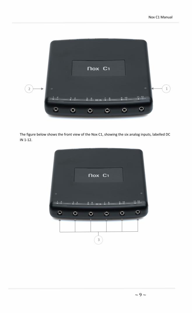
The figure below shows the top view of the Nox C1, showing the device’s status LED (1) and the
ambient light sensor (2). For device status indicated with the LED, refer to the “Device Status”
section.
* Currently the USB ports do not have any function
Nox C1 Manual
~ 9 ~
The figure below shows the front view of the Nox C1, showing the six analog inputs, labelled DC
IN 1-12.
3
2 1

Nox C1 Manual
~ 10 ~
The figure below shows the rear of the Nox C1, showing the six inputs available. Refer to the
table below for input definition.
The following table lists the Nox C1 access point inputs and the corresponding input labeling.
NUMBER FUNCTION INPUT/SENSOR LABEL
1 Indicator light for device status No label on device
2 Ambient light sensor No label on device
3 Analog inputs DC IN 1-12
4 Ethernet cable input LAN
5 Factory reset button No label on device
6 USB inputs* USB
7 Serial inputs 1 COM 2
8 Differential pressure sensor
inputs + PRES -
9 DC power supply connector
* Currently the USB ports do not have any function
9 8 7 6 5 4

Nox C1 Manual
~ 11 ~
OPERATING NOX C1
The Nox C1 Access Point is only intended to be operated by professionals (healthcare
professionals and service personnel) with relevant qualification in hospitals, institutions, sleep
centers, sleep clinics or other test environment, not including the patient’s home.
Connect to DC Power
Warning: Only use power supply FRIWO MP115 Medical-7555M/12 with the
Nox C1 access point. The use of an incorrect power supply may result in
electric shock or cause the device to overheat, which may result in
patient/operator harm.
The Nox C1 is powered by FRIWO MP115 Medical-7555M/12, a specific medical grade power
supply rated with operating voltage of 12 volts and providing medical grade isolation from
mains. Connect the power supply into the DC power connector on the rear of the device and
have the applicable regional adapter connected to the power supply.
Verify that the LED indicator light on top of the Nox C1 access point starts blinking amber
immediately after connection of the power supply and starts blinking green when the startup
sequence of the device is completed and the Nox C1 is available for configuration.
FRIWO MP115 Medical-7555M/12 (FW7555M/12)
The medical grade power supply FRIWO MP115 Medical-7555M/12 is the only power supply that
should be used with the Nox C1 access point to ensure safe and effective device operation. The
LED indicator is the operating indicator. For detailed user instructions, product specifications and
regulatory information please refer to the Nox Medical web page.
Caution: In the case of visible damages on the housing or on the cord do not
use the power supply.
Warning: The device should never be operated or even stored at places listed
below, because this could lead to operating failures:
o Places, which are heavily exposed to moisture or where water

Nox C1 Manual
~ 12 ~
condensing may occur
o Places, which are exposed to special environmental conditions
o Places, which are subject to constant vibrations
o Places, which are subject to high temperature fluctuations
o Outdoors
Caution: Always disconnect the power supply from mains during lighting
storms or when not in use.
Caution: The power supply itself is the disconnect device. Never use the cord
to pull the power supply from the mains.
Warning: The power supply is maintenance free. It must not be opened. (Risk
of electrical shock).
Warning: A modification of the power supply is not allowed.
Warning: The device may only be repaired by authorized personnel.
Warning: Remove from mains before cleaning. Do not clean with detergents.
Clean only with a dry cloth.
NOTE: The power supply unit is intended for supplying end medical product
by its output voltage.
Warning: The unit shall not be used for use in an oxygen rich environment.
Warning: The unit it is not intended to be used with flammable anesthetics
and not intended for use in conjunction with flammable agents.
Nox C1 Status
The Nox C1 access point has a built-in LED for device status indication. The LED is located on the
top panel of the device. Refer to the table below for a description of the different states of the
Nox C1 indicated with the LED.
Status Light Description
Off Nox C1 is not connected to power and is turned off
Blinking amber Nox C1 is connected to power and is completing the startup
sequence
Blinking green Nox C1 is connected to power and ready to use. A recording is
not running
Solid green A recording is running
Solid amber Firmware error indication, Nox C1 is not functional
Nox C1 should be factory reset (refer to section “Factory Reset”)
Alternating green and
amber
Firmware upgrade/factory reset is running

Nox C1 Manual
~ 13 ~
The LED brightness will automatically dim during a recording to ensure patient comfort.
Nox C1 Analog Inputs
Warning: The analog channels on the Nox C1 access point are signal input/output (SIP/SOP) auxiliary ports not to be connected in direct galvanic connection to the patient. This could result in electric shock.
The Nox C1 access point is equipped with 12 analog channels suitable for collecting of DC signals
from auxiliary devices. The channels are collected on 6 inputs, labeled DC IN from 1 to 12 on the
top of the device. The analog inputs which are 3.5 mm female stereo jack and yields 2 channels
each. The voltage range allows interfacing signals from -5 V to +5 V.
Auxiliary devices can be connected to the Nox C1 analog inputs using a standard 3.5 mm male
stereo jack or a 3.5 mm male mono jack.
The 12 analog channels offered by the Nox C1 have six inputs labeled DC IN from 1 to 12, see the
figure above. The table below addresses the channel identification.
Analog Inputs Analog Channels 1-12
Analog Input 1 and 2 Channel 1
Channel 2
Analog Input 3 and 4 Channel 3
Channel 4
Analog Input 5 and 6 Channel 5
Channel 6
Analog Input 7 and 8 Channel 7
Channel 8
Analog Input 9 and 10 Channel 9
Channel 10
Analog Input 11 and 12 Channel 11
Channel 12

Nox C1 Manual
~ 14 ~
The table below lists available commercial connectors that can be used for connection to the
Nox C1 analog channel inputs.
Connector Type Channel Identification
3,5 mm male
stereo jack
A stereo jack can carry two
analog channels (e.g. channels
1 and 2)
3,5 mm male
mono jack
A mono connector can carry
one analog channel (e.g.
channel 1)
For the analog channel specifications refer to the “Specifications” section. Please refer to the
Noxturnal manual for more information on how to configure and license the analog channels.
Nox C1 Differential Pressure Sensor
To setup the Nox C1 access point for a recording of patient airflow at the proximal airway when using a CPAP device, connect two Nox filter tube connectors to the differential pressure sensor inputs on the rear of the device, labelled + PRES -. The differential pressure sensor inputs are designed to fit directly with the filter tube connector interface from Nox Medical. The figure below shows the Nox filter tube connectors connected to the differential pressure sensor inputs.
For the differential pressure sensor specifications refer to the “Specifications” section.
Nox C1 Serial Inputs
Warning: The serial channels on the Nox C1 access point are signal input/output (SIP/SOP) auxiliary ports not to be connected in direct galvanic connection to the patient. This could result in electric shock.
Odd number channel
Even number channel GND
Odd number channel
GND

Nox C1 Manual
~ 15 ~
To record signals from auxiliary devices over a serial connection connect a 3.5 mm male stereo
jack carrying the serial signal to a COM input on the rear of the Nox C1 access point. The figure
below shows the rear of the device, where the serial inputs are located. The serial inputs are
labelled 1 COM 2. For the serial input specifications refer to the “Specifications” section.
Connector Type Channel Identification
3,5 mm male
stereo jack
The COM stereo jacks carry
one serial channel each with
TxD, RxD and GND at RS232
levels.
Nox C1 Serial-over-USB Inputs
Warning: The USB channels on the Nox C1 access point are signal input/output (SIP/SOP) auxiliary ports not to be connected in direct galvanic connection to the patient. This could result in electric shock.
The Nox C1 access point contains USB ports that currently do not have any function within the
Nox Sleep System. The USB inputs are on the rear of the device. The figure below shows the rear
of the device, where the USB inputs are located. The USB inputs are labelled USB. For the USB
input specifications refer to the “Specifications” section.
TxD
RxD
GND
Nox C1 Manual
~ 16 ~
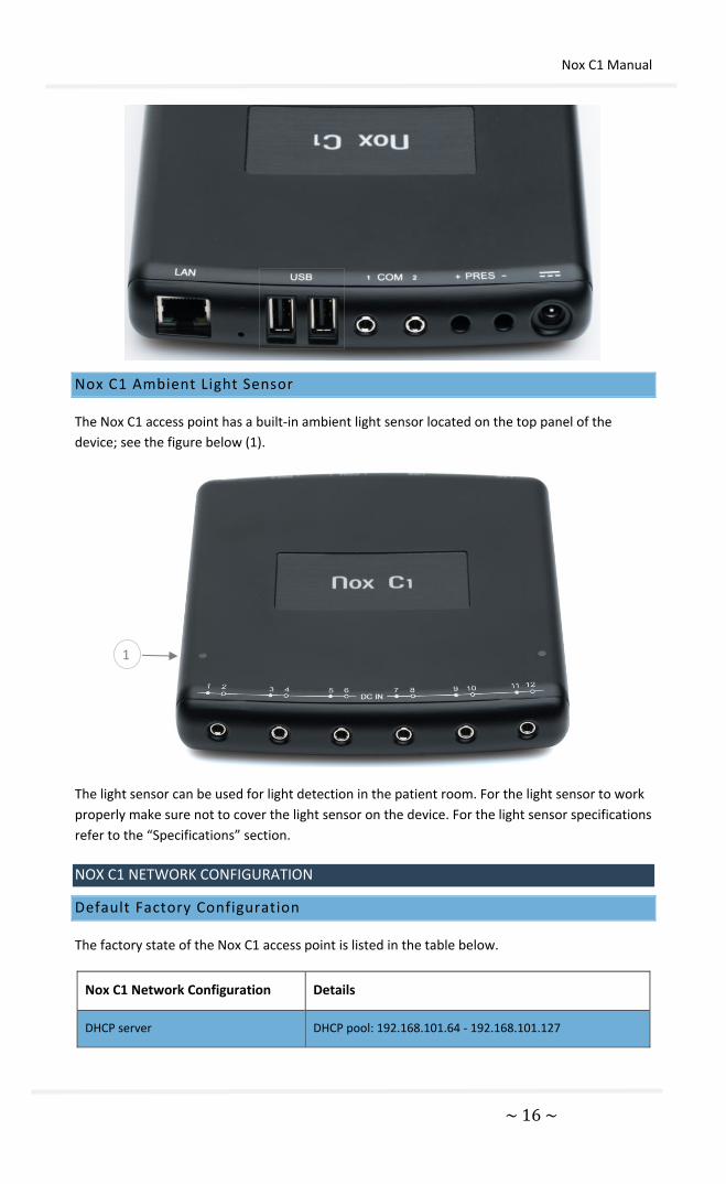
Nox C1 Ambient Light Sensor
The Nox C1 access point has a built-in ambient light sensor located on the top panel of the
device; see the figure below (1).
The light sensor can be used for light detection in the patient room. For the light sensor to work
properly make sure not to cover the light sensor on the device. For the light sensor specifications
refer to the “Specifications” section.
NOX C1 NETWORK CONFIGURATION
Default Factory Configuration
The factory state of the Nox C1 access point is listed in the table below.
Nox C1 Network Configuration Details
DHCP server DHCP pool: 192.168.101.64 - 192.168.101.127
1
Nox C1 Manual
~ 17 ~
Static IP address 192.168.101.10
Universal Plug and Play (UPnP)
discovery
Networking protocol that permits the Nox C1 to be
discovered on a network
The Nox C1 network configuration can be managed through the Noxturnal software. Please refer
to the Noxturnal manual for instructions on how to configure the Nox C1 network settings.
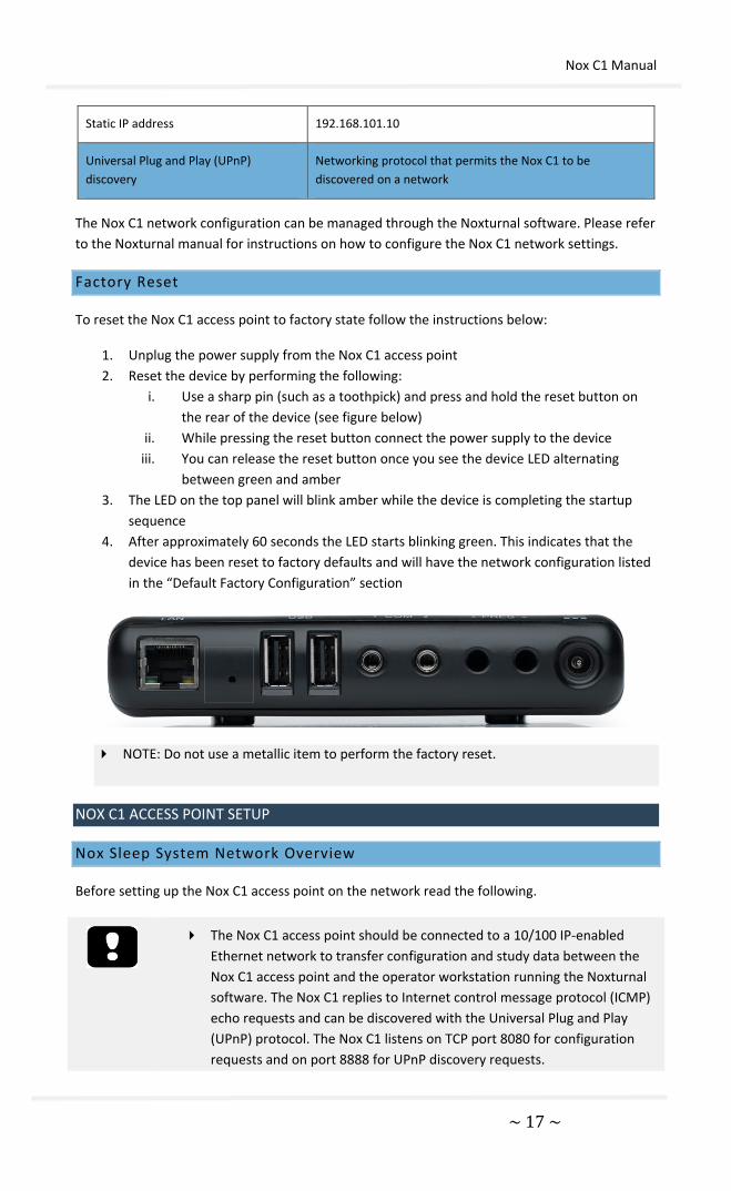
Factory Reset
To reset the Nox C1 access point to factory state follow the instructions below:
1. Unplug the power supply from the Nox C1 access point
2. Reset the device by performing the following:
i. Use a sharp pin (such as a toothpick) and press and hold the reset button on
the rear of the device (see figure below)
ii. While pressing the reset button connect the power supply to the device
iii. You can release the reset button once you see the device LED alternating
between green and amber
3. The LED on the top panel will blink amber while the device is completing the startup
sequence
4. After approximately 60 seconds the LED starts blinking green. This indicates that the
device has been reset to factory defaults and will have the network configuration listed
in the “Default Factory Configuration” section
NOTE: Do not use a metallic item to perform the factory reset.
NOX C1 ACCESS POINT SETUP
Nox Sleep System Network Overview
Before setting up the Nox C1 access point on the network read the following.
The Nox C1 access point should be connected to a 10/100 IP-enabled
Ethernet network to transfer configuration and study data between the
Nox C1 access point and the operator workstation running the Noxturnal
software. The Nox C1 replies to Internet control message protocol (ICMP)
echo requests and can be discovered with the Universal Plug and Play
(UPnP) protocol. The Nox C1 listens on TCP port 8080 for configuration
requests and on port 8888 for UPnP discovery requests.

Nox C1 Manual
~ 18 ~
Any study data collected during a network outage is discarded and the
user will be notified in Noxturnal if such an event occurs.
NOTE: If the Nox C1 access point is connected to a shared network please
make sure that any device connected to the network does not cause
network congestion reducing the operational integrity of the Nox C1
access point.
To ensure steady operation of the Nox Sleep System please follow the recommended system
setup below.
Use a separate local area network (LAN) for each Nox C1 access point and a computer
running the Noxturnal software, i.e. each patient room that includes the Nox C1 should
be on a separate network.
Use a separate Nox C1 access point for each Nox A1 recorder to be used.
Use a separate computer running Noxturnal for each Nox C1 access point.
The table below describes the setup of the control room where the computer with Noxturnal
installed is located.
Control Room
Item Connection
PC Connected to the same network as the Nox C1
with a network cable
Noxturnal Installed on PC
The table below describes the setup of the patient room where the patient is sleeping during a
sleep study.
Patient Room
Item Name Description Function Setup/Connection
Nox C1 Access Point
Bluetooth access point with analog and serial inputs and built in light sensor and differential pressure sensor
Data transfer received from Nox A1 over Bluetooth connection and forwarded to Noxturnal via Ethernet
Commands received from Noxturnal via Ethernet and forwarded to Nox A1 using Bluetooth connection
Data transfer received from auxiliary devices connected to analog and/or serial inputs and forwarded to Noxturnal via Ethernet
Located in the patient room. Connected to the same LAN as the PC running the Noxturnal software
Nox A1 Recording device Records physiological Attached to the

Nox C1 Manual
~ 19 ~
Recorder and applicable sensors
that may be configured for different types of sleep studies
signals from built-in and attached sensors
patient in the patient room
Medical auxiliary devices
Any medical device that fits the input channel specifications of the Nox C1 Access Point. Medical devices supported by the system to be connected to Nox A1 Recorder via Bluetooth link
Depends on the auxiliary device being used
The applicable connection cable connected to the analog input/serial on the Nox C1 Access Point. Via Bluetooth link to the Nox A1 recorder
Noxturnal App
Android App
Can be used to connect to Online Rooms, review signal traces and perform bio calibration and impedance check. Can also be used to start and stop recordings
Set the App to Online Mode and connect to the applicable online room
The figure below shows the overview of the online setup for the Nox Sleep System .
The Nox C1 Access Point is operated by the Noxturnal software. For instructions on how to configure and operate the Nox C1 Access Point and Nox A1 Recorder from the Noxturnal software refer to the Noxturnal manual.
MAINTENANCE
The Nox Sleep System is only intended to be maintained by professionals (healthcare
professionals and service personnel) with relevant qualifications and skills.
The Nox C1 Access Point and accessories should be stored in a clean, dry place.
Handle the Nox C1 Access Point with care and protect it against mechanical shocks, dirt, and
liquids. The device is not waterproof or splash proof.
Nox C1 Manual
~ 20 ~
To update the Nox C1 firmware you will need the Noxturnal software running on a computer
which is on the same network as the Nox C1 Access Point. Please refer to the Noxturnal manual
for more information on how to perform this task.
No regular testing of the Nox C1 access point is needed.
The service life of the Nox C1 Access Point and the FRIWO MP115 Medical-7555M/12 power
supply is 5 years.
Environmental Conditions
Note: The environmental conditions listed below apply both for the Nox C1 Access Point and the accompanying FRIWO MP115 Medical-7555M/12 power supply.
Temperature
Operation: +5°C to +40°C (41°F to 104°F)
Transport/Storage: -25°C to +70°C (-13°F to 158°F)
Relative Humidity Operation: 15-90% (non-condensing)
Transport/Storage: 10-95% (non-condensing)
Pressure Withstands atmospheric pressures from 700 hPa to 1060 hPa
Calibration
The Nox C1 Access Point is factory calibrated. No further calibration is needed.
Warning: There are no user serviceable parts inside the Nox C1 Access Point. The device should be serviced by authorized parties only. Service performed by non-authorized parties may affect data analysis and result in possible incorrect treatment. The warranty is void if the Nox C1 Access Point is opened.
Warning: No modification of the Nox C1 Access Point is allowed. Un-authorized modifications may affect data analysis and result in possible incorrect treatment.
Cleaning
Warning: The Nox C1 Access Point device is not designed to give a specified
degree of protection against harmful ingress of liquids. Do not autoclave or
immerse the device in any kind of liquids. Ingress of liquids may result in
electric shock.
Warning: In the United States of America, only use United States
Environmental Protection Agency (EPA) registered products for cleaning of the
Nox C1 Access Point to prevent harm to the operator/patient

Nox C1 Manual
~ 21 ~
The Nox C1 Access Point is NOT intended to be sterilized.
Clean the Nox C1 Access Point with a soft cloth dampened with hospital grade cleaner that is not
corrosive to plastic or metal. Do not pour or spray any liquids onto the device, and do not allow
any liquids to enter any openings on the device. Allow the unit to dry thoroughly before use.
For disinfection of the Nox C1 Access Point the following materials may be used:
• Sodium hypochlorite diluted with water at 1:500 (bleach)
• 70-90% isopropanol
• Super Sani-Cloth Plus disinfection wipes (from PDI)
For cleaning of FRIWO MP115 Medical-7555M/12 power supply only use dry cloth. Do not clean
with detergents.
Warning: Remove from mains before cleaning. Do not clean with detergents.
Clean only with a dry cloth
Disposal
According to the regulation in Europe on Waste of Electrical and Electronic
Equipment (WEEE) the components labeled with this symbol may not be
disposed of as unsorted municipal waste. The components shall be collected
separately and returned to the appropriate collection system available.
Please contact your sales representative regarding take-back or recycling of the
components.
Follow local governing ordinances and recycling instructions regarding disposal or recycling of
the Nox C1 Access Point and accessories.
COMPATIBLE DEVICES, SENSORS AND ACCESSORIES
Warning: Do not use damaged equipment, sensors or accessories. This may
result in bad performance of the device or patient/operator injury.
Warning: External equipment and all auxiliary devices intended for connection
to signal input, signal output or other connectors shall comply with the
relevant product safety standards, e.g. IEC 60950-1 for IT equipment and the
IEC 60601 series for medical electrical equipment, to prevent electric shocks.
In addition, all such combinations – systems – shall comply with the safety
requirements stated in the general standard IEC 60601-1, edition 3/3.1, clause
16. Any equipment not complying with the leakage current requirements in
IEC 60601-1 shall be kept outside the patient environment i.e. at least 1.5 m
from the patient support. Any person who connects external equipment to
signal input, signal output or other connectors has formed a system and is
therefore responsible for the system to comply with the requirements. If in
doubt, contact a qualified medical technician or your local representative.
Caution: After connecting a new auxiliary signal to the C1 connectors OR after
modifying the connection of the auxiliary signals OR after changing the mode

Nox C1 Manual
~ 22 ~
of the auxiliary devices signal output, always verify the correct setup by
performing an actual recording, making the auxiliary device create a known
signal, and monitoring the appearance and values measured in the recording
software, in order to prevent signals that would lead to incorrect
interpretation and possible incorrect treatment.
Warning: All the auxiliary devices connected to the C1 device should be
powered from a single power strip to ensure a common ground, avoid ground
potential difference skewing or disturbing the signals and thus prevent
possible incorrect treatment.
The following table includes information on accessories, sensors and devices that have been
validated with the Nox C1 Access Point.
The items listed below are Nox products and have been validated for use with the Nox C1 Access
Point:
NOX FILTER TUBE CONNECTORS
Type Catalog Number
Nox Filter Tube Connector, 50 units 552110
NOX SLEEP SYSTEM COMPONENTS
Type Catalog Number
Nox A1 System Kit 513010
Nox A1 Recorder 561410
Noxturnal CD 539010
Noxturnal NA
Noxturnal App 536210
Nox C1 Access Point 544020
POWER SOURCE
Type Catalog Number
FRIWO MP115 Medical-7555M/12 NA*
*The 3rd party FRIWO MP115 Medical-7555M/12 medical grade power supply has been validated with the Nox C1 Access
point and is included in the C1 Kit. C1 Kit has the catalog number 544020
The items listed below are 3rd party products and have been validated for use with the Nox C1
Access Point:

Nox C1 Manual
~ 23 ~
ACCESSORIES FOR DIFFERENTIAL PRESSURE SENSOR
Type Catalog Number
Mask tubing 183 cm (72 in) Female x Male 552320
Pneumoflow Sensor 552810
CLEANING
Type Catalog Number
Super Sani-Cloth Plus Disinfection Wipes 559010
SPECIFICATIONS
Nox C1 Access Point and Power Supply
DESCRIPTION PROPERTIES
FUNCTION
Nox C1 Channels Ambient Light Channel
Differential Pressure Channel
Twelve Analog Input Channels (DC)
Two USB Input Channels*
Two Serial Input Channels
PHYSICAL
Nox C1 Dimensions 135 mm x 149 mm x 26 mm (5.3" x 5.9" x 1.0")
Nox C1 Weight 264 g (9.3 oz)
Nox C1 DC Inputs Number of Channels: 12
Number of Inputs: 6
Input Voltage Range: +/- 5 V
Sampling: 16 bit, 250 sample/s
Connector: 3.5 mm Female Stereo Jack
Nox C1 Light Sensor
Input
Light Range: Can distinguish between dark room and
a slightly lit room
Sampling: 16 bit, 250 sample/s
Nox C1 Light Indicator Number of LEDs: 1
Colors: Green and Amber for status indication
* Currently the USB ports do not have any function

Nox C1 Manual
~ 24 ~
Nox C1 Pressure Sensor
Input
Number of Channels: 1
Number of Inputs: 2
Absolute Maximum Input Pressure: +/- 7 kPa
Pressure Input Range: +/- 40 cmH2O
Sampling: 16 bit, 250 sample/s
Connector: Differential sensor port
Nox C1 USB Inputs
(currently nonfunctional)
Number of Channels: 2
Number of Inputs: 2
USB 2.0 compliance
High Speed (up to 480 Mbit/s)
Connector: USB Type A
Nox C1 Serial Inputs Number of Channels: 2
Number of Inputs: 2
RS-232
Connector: 3.5 mm Female Stereo Jack
POWER SUPPLY
Power Supply Model FRIWO MP115 Medical-7555M/12
Nominal Input Voltage 100-240 V AC +/- 10%
Nominal Input
Frequency
50-60 Hz
Nominal Input Current 0.350-0.150 Arms (at max load)
Nominal Output Voltage 12 V DC +/- 5%
Nominal Output Current 0-1250 mA
COMMUNICATION
Nox C1 Bluetooth® Bluetooth® v.4.0
Bluetooth Classic and Bluetooth Low Energy dual
mode compliant
Operating frequency: 2.402-2.480 GHz
Bandwidth: 2 MHz
Transmit power: 10 mW max.
Range: up to 35 meters in line-of-sight
Antenna type: Internal
Network Topology: Point-to-Point: Point-to-
Multipoint
Operation: Scatter-Net Master
Modulation Type: Frequency Shift Keying/Frequency
Hopping Spread Spectrum
Nox C1 Ethernet Number of Inputs: 1
10/100 BASE-TX
Connector: RJ-45
REGULATORY INFORMATION
Performance Testing and Validation Summary
The Nox Sleep System has been tested and verified in various phases to include internal testing,
verification and validation as well as external testing to assure product safety, effectiveness and
reliability. The design was verified and validated, including clinical evaluation, throughout the
design process, according to requirement specifications and intended use. External accredited
test houses were used to conduct testing needed to comply with the applicable standards
regarding EMC and patient safety as well as additional RF testing to assure compliance to Radio
and Telecommunication Terminal Equipment (R&TTE) Directive (R&TTE).

Nox C1 Manual
~ 25 ~
Nox Medical holds a ISO 13485:2016 certified Quality Management System which complies with
the requirements of the Medical Device Directive (MDD), FDA Quality System Regulation (QSR)
and Canada Medical Device Regulations (CMDR).
Nox C1 Classification
Degree of protection against electric shock: The device is classified as class II
equipment (see the symbol to the left).
Powering of the device: The device is powered from an external electrical
power source.
Degree of protection against harmful ingress of liquids and particulate matter:
The Nox C1 Access Point is classified IP20, i.e., as defined by the standard IEC
60529 it is protected against solid foreign objects of 12,5 mm diameter and
greater, but it is not protected against harmful ingress of liquids.
Method of sterilization: The device is NOT delivered sterile or intended to be
sterilized.
Suitability for use in an oxygen rich environment: The device is NOT intended
for use in an oxygen rich environment.
Suitability for use with flammable agents and anesthetics: The device is NOT
intended for use in conjunction with flammable agents or with flammable
anesthetic mixture with air or with oxygen or nitrous oxide.
Mode of operation: The device is intended for continuous operation.
Description of Symbols and Labels
Operating instructions / Consult instructions for use
Caution
Manufacturer information
Date of manufacture
Serial number
Catalogue number / Reference number

Nox C1 Manual
~ 26 ~
(01)15694311110590(11)YYMM
DD(21)931XXXXXX
Unique Device Identifier (UDI); the Application Identifier (01) represents the device identifier (DI) (“15694311110590”), the Application Identifier (11) the production date/date of manufacture (“YYMMDD”, with “YY” the last two digits of the production year, “MM” the production month and “DD” the production day), and the Application Identifier (21) the serial number of the device (“931XXXXXX”)
Class II equipment
In compliance with the European Directive on Waste of Electrical and Electronic Equipment (WEEE) 2002/96/EC, do not dispose of this product as unsorted municipal waste
Non-ionizing radiation. The equipment includes a RF transmitter: interference may occur in the vicinity of equipment marked with this symbol
CE marking indicating conformance to EC directives 93/42/EEC and 2007/47/EC concerning medical devices
Bluetooth® wireless technology
Federal Communications Commission (FCC) logo
Keep dry
Fragile, handle with care
Temperature limit
Humidity limitation
Atmospheric pressure limitation

Nox C1 Manual
~ 27 ~
Contains IC ID: 5123A-BGTBT111 Industry Canada (IC) ID label
Contains FCC ID: QOQBT111 Federal Communications Commission (FCC) ID label
DC IN 1-12 Analog inputs (DC)
LAN Ethernet cable input
USB USB inputs (currently nonfunctional)
1 COM 2 Serial inputs
+ PRES - Differential pressure sensor inputs
DC power supply connector
Bluetooth® Wireless Technology
The Nox C1 Access Point uses Bluetooth® 4.0 wireless technology to communicate with external
Bluetooth modules.
The Bluetooth wireless technology is based on a radio link that offers fast and reliable
transmission of data. Bluetooth radio uses globally available frequency range in the industrial,
scientific, and medical (ISM) band, intended to ensure communication compatibility worldwide
and a fast acknowledgement and frequency-hopping scheme to make the link robust, even in
noisy radio environments. Please refer to the “Specifications” section for details on Radio
Frequency (RF) specifications for the Nox C1 Access Point.
The Bluetooth® word mark and logos are registered trademarks owned by the Bluetooth SIG, Inc.
and any use of such marks by Nox Medical is under license. Other trademarks and trade names
are those of their respective owners.
Electromagnetic Compatibility (EMC) Information
Portable and mobile RF communications can affect the performance of the Nox C1 Access Point.
Warning: Electromagnetic interference (EMI) can be picked up by the analog channels of the Nox C1 Access point, causing disturbed or altered signals to appear in the Noxturnal software. This may affect data analysis and result in possible incorrect treatment.
Warning: The Nox C1 access point(s) should not be used adjacent to or stacked with other equipment. If adjacent or stacked use is necessary, the device(s) should be observed to verify normal operation in the configuration in which it will be used and prevent abnormal operation which might cause injuries to the operator/patient.
Warning: The use of accessories, transducers, sensors, and cables other than those listed in this manual may result in increased emissions and/or decreased immunity of this device and cause injuries to the operator/patient.
Warning: The Nox Sleep System may be interfered with by other equipment, even if that equipment complies with CISPR (Special International Committee

Nox C1 Manual
~ 28 ~
on Radio Interference) emission requirements, causing possible patient harm.
Refer to the tables below in this section for specific information regarding the Nox C1 Access Point’s compliance to the standard IEC60601-1-2: Medical electrical equipment - Part 1-2: General requirements for basic safety and essential performance - Collateral Standard: Electromagnetic disturbances - Requirements and tests.
Declarations of Conformity with the US Federal Communications Commission
(FCC) and Industry Canada Regulations
USA - FEDERAL COMMUNICATIONS COMMISSION (FCC)
The Nox C1 Access Point complies with Part 15 of the FCC Rules. Operation is subject to the
following two conditions:
1. This device may not cause harmful interference, and
2. This device must accept any interference, including interference that may cause undesired operation of this device.
FCC RF Radiation Exposure Statement:
This equipment complies with FCC radiation exposure limits set forth for an uncontrolled
environment. End users must follow the specific operating instructions for satisfying RF exposure
compliance. This transmitter meets both portable and mobile limits as demonstrated in the RF
Exposure Analysis and should not be used closer than 5 mm from a human body in portable
configuration. This transmitter must not be co-located or operating in conjunction with any
other antenna or transmitter except in accordance with FCC multi-transmitter product
procedures.
CANADA - INDUSTRY CANADA (IC)
the Nox C1 Access point complies with Industry Canada license-exempt RSS standard(s).
Operation is subject to the following two conditions:
(1) this device may not cause interference, and
(2) this device must accept any interference, including interference that may cause undesired
operation of the device.
Under Industry Canada regulations, this radio transmitter may only operate using an antenna of a type and maximum (or lesser) gain approved for the transmitter by Industry Canada. To reduce potential radio interference to other users, the antenna type and its gain should be so chosen that the equivalent isotropically radiated power (e.i.r.p.) is not more than that necessary for successful communication.
COMPLIANCE WITH FCC AND INDUSTRY CANADA REGULATIONS
• The antenna(s) must be installed such that a minimum separation distance of 5 mm is
maintained between the radiator (antenna) and all persons at all times.
Nox C1 Manual
~ 29 ~
• The transmitter module must not be co-located or operating in conjunction with any
other antenna or transmitter except in accordance with FCC multi-transmitter product
procedures.
MODIFICATION STATEMENT
Any changes or modifications not expressly approved by Nox Medical could void the user’s
authority to operate the equipment.
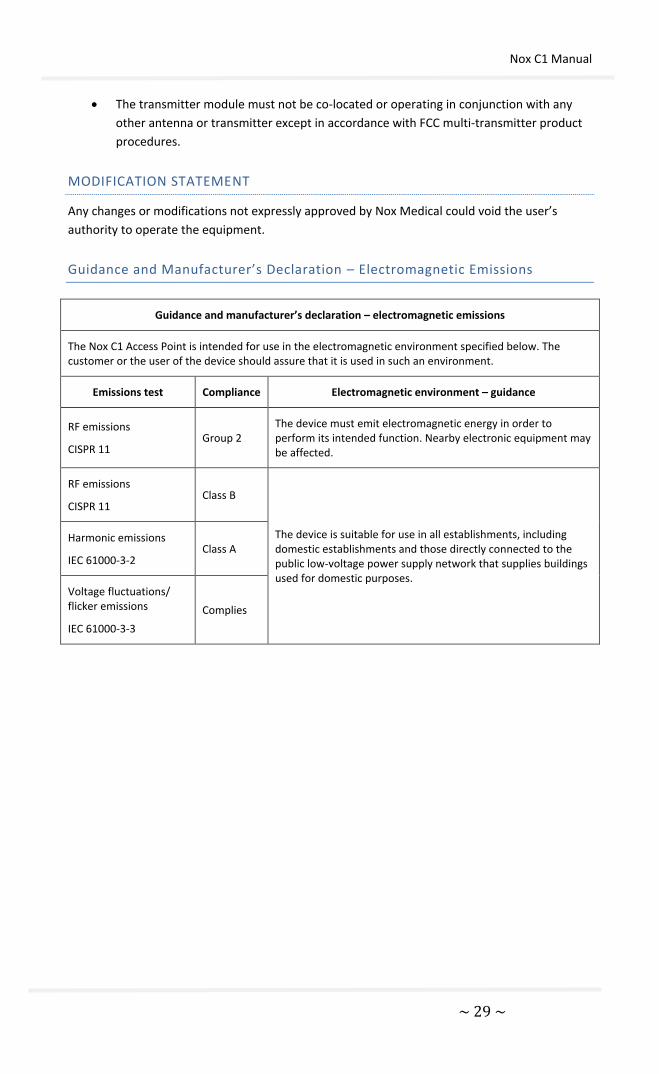
Guidance and Manufacturer’s Declaration – Electromagnetic Emissions
Guidance and manufacturer’s declaration – electromagnetic emissions
The Nox C1 Access Point is intended for use in the electromagnetic environment specified below. The customer or the user of the device should assure that it is used in such an environment.
Emissions test Compliance Electromagnetic environment – guidance
RF emissions
CISPR 11 Group 2
The device must emit electromagnetic energy in order to perform its intended function. Nearby electronic equipment may be affected.
RF emissions
CISPR 11 Class B
The device is suitable for use in all establishments, including domestic establishments and those directly connected to the public low-voltage power supply network that supplies buildings used for domestic purposes.
Harmonic emissions
IEC 61000-3-2 Class A
Voltage fluctuations/ flicker emissions
IEC 61000-3-3
Complies
Nox C1 Manual
~ 30 ~
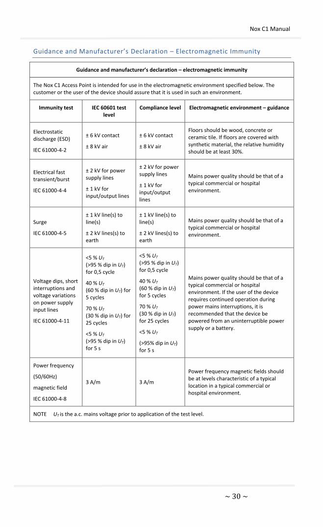
Guidance and Manufacturer’s Declaration – Electromagnetic Immunity
Guidance and manufacturer’s declaration – electromagnetic immunity
The Nox C1 Access Point is intended for use in the electromagnetic environment specified below. The customer or the user of the device should assure that it is used in such an environment.
Immunity test IEC 60601 test level
Compliance level Electromagnetic environment – guidance
Electrostatic discharge (ESD)
IEC 61000-4-2
± 6 kV contact
± 8 kV air
± 6 kV contact
± 8 kV air
Floors should be wood, concrete or ceramic tile. If floors are covered with synthetic material, the relative humidity should be at least 30%.
Electrical fast transient/burst
IEC 61000-4-4
± 2 kV for power supply lines
± 1 kV for input/output lines
± 2 kV for power supply lines
± 1 kV for input/output lines
Mains power quality should be that of a typical commercial or hospital environment.
Surge
IEC 61000-4-5
± 1 kV line(s) to line(s)
± 2 kV lines(s) to earth
± 1 kV line(s) to line(s)
± 2 kV lines(s) to earth
Mains power quality should be that of a typical commercial or hospital environment.
Voltage dips, short interruptions and voltage variations on power supply input lines
IEC 61000-4-11
<5 % UT (>95 % dip in UT) for 0,5 cycle
40 % UT (60 % dip in UT) for 5 cycles
70 % UT (30 % dip in UT) for 25 cycles
<5 % UT (>95 % dip in UT) for 5 s
<5 % UT (>95 % dip in UT) for 0,5 cycle
40 % UT (60 % dip in UT) for 5 cycles
70 % UT (30 % dip in UT) for 25 cycles
<5 % UT
(>95% dip in UT) for 5 s
Mains power quality should be that of a typical commercial or hospital environment. If the user of the device requires continued operation during power mains interruptions, it is recommended that the device be powered from an uninterruptible power supply or a battery.
Power frequency
(50/60Hz)
magnetic field
IEC 61000-4-8
3 A/m 3 A/m
Power frequency magnetic fields should be at levels characteristic of a typical location in a typical commercial or hospital environment.
NOTE UT is the a.c. mains voltage prior to application of the test level.

Nox C1 Manual
~ 31 ~
Guidance and Manufacturer’s Declaration – Electromagnetic Immunity
(Continued)
Guidance and manufacturer’s declaration – electromagnetic immunity
The Nox C1 Access Point is intended for use in the electromagnetic environment specified below. The
customer or the user of the device should assure that it is used in such an environment.
Immunity test IEC 60601 test level
Compliance level Electromagnetic environment – guidance
Portable and mobile RF communications equipment should be used no closer to any part of device, including cables, than the recommended separation distance calculated from the equation applicable to the frequency of the transmitter.
Recommended separation distance
Conducted RF
IEC 61000-4-6
3 Vrms
150 kHz to 80 MHz 3 V d = 1.2 √P
Radiated RF
IEC 61000-4-3
3 V/m
80 MHz to 2.5 GHz 3 V/m
d = 1.2 √P 80 MHz to 800 MHz
d = 2.3 √P 800 MHz to 2.5 GHz
where P is the maximum output power rating of the transmitter in watts (W) according to the transmitter manufacturer and d is the recommended separation distance in meters (m).
Field strengths from fixed RF transmitters, as determined by an electromagnetic site survey,a should be less than the compliance level in each frequency range.b
Interference may occur in the vicinity of equipment marked with the following symbol:
NOTE 1 At 80 MHz and 800 MHz, the higher frequency range applies.
NOTE 2 These guidelines may not apply in all situations. Electromagnetic propagation is affected by absorption and reflection from structures, objects and people.

Nox C1 Manual
~ 32 ~
a Field strengths from fixed transmitters, such as base stations for radio (cellular/cordless) telephones and land mobile radios, amateur radio, AM and FM radio broadcast and TV broadcast cannot be predicted theoretically with accuracy. To assess the electromagnetic environment due to fixed RF transmitters, an electromagnetic site survey should be considered. If the measured field strength in the location in which the Nox C1 Access Point is used exceeds the applicable RF compliance level above, the device should be observed to verify normal operation. If abnormal performance is observed, additional measures may be necessary, such as reorienting or relocating the device.
b Over the frequency range 150 kHz to 80 MHz, field strengths should be less than 3 V/m.
Recommended Separation Distance between Portable and Mobile RF
Communications Equipment and the Nox C1 Access Point
Recommended separation distance between portable and mobile RF communications equipment and the C1 device
The Nox C1 Access Point is intended for use in an electromagnetic environment in which radiated RF disturbances are controlled. The customer or the user of the device can help prevent electromagnetic interference by maintaining a minimum distance between portable and mobile RF communications equipment (transmitters) and the device as recommended below, according to the maximum output power of the communications equipment.
Rated maximum output
power of transmitter
W
Separation distance according to frequency of transmitter
m
150 kHz to 80 MHz
d = 1.2 √P
80 MHz to 800 MHz
d = 1.2 √P
800 MHz to 2.5 GHz
d = 2.3 √P
0.01 0.12 0.12 0.23
0.1 0.38 0.38 0.73
1 1.2 1.2 2.3
10 3.8 3.8 7.3
100 12 12 23
For transmitters rated at a maximum output power not listed above, the recommended separation distance d in meters (m) can be estimated using the equation applicable to the frequency of the transmitter, where P is the maximum output power rating of the transmitter in watts (W) according to the transmitter manufacturer.
NOTE 1 At 80 MHz and 800 MHz, the separation distance for the higher frequency range applies.
NOTE 2 These guidelines may not apply in all situations. Electromagnetic propagation is affected by absorption and reflection from structures, objects and people.

Nox C1 Manual
~ 33 ~
ABOUT
This manual and associated translations are also provided in electronic format according to
Commission Regulation (EU) No 207/2012 of 9 March 2012 on electronic instructions for use of
medical devices. They are available in electronic format on Nox Medical's website:
www.noxmedical.com.
Electronic versions are provided as PDF documents and a PDF reader is required to open the
documents. PDF readers are commonly available at no cost for users. Refer to the applicable
system and hardware requirements for the PDF reader that is used.
Hard copies can be requested at no additional cost by emailing [email protected]. The
hard copy will be sent within 7 calendar days.