manual of modern hydronics - the radiant store inc
TRANSCRIPT

Manual ofModernHydronics
• Resident ia l
• Industr ia l
• Commercia l
• Snow and Ice Melt
Profess ional Radiant Heat ing Solut ions
S E C O N D E D I T I O N

MA N UA L O F MO D E R N HY D R O N I C S
This manual is published in good faith and is believed to be
reliable. Data presented is the result of laboratory tests and
field experience.
IPEX maintains a policy of ongoing product improvement. This
may result in a modification of features or specifications
without notice.
www.warmrite.com
www.ipexinc.com
© 2004 by IPEX. All rights reserved. No part of this book may
be used or reproduced in any manner whatsoever without prior
written permission. For information, address IPEX, Marketing,
2441 Royal Windsor Drive, Mississauga, Ontario L5J 4C7.
© 2004 IPEX WR003UC
INTRODUCTION
MODERN HYDRONICS
Each year, construction begins on tens of thousands of new buildings all across North America. Thousands moreundergo renovation. Whether new or remodeled, most of these buildings will require the installation or alterationof a comfort heating system. Along with hundreds of other decisions, the owners of these buildings musteventually select a heating system.
Unfortunately—and in most cases unintentionally—the choice is often based on factors that in the end, don’tprovide the comfort the owner or the occupants are expecting.
In many cases the heating system, which is often thought of as a necessary but uninspiring part of the building,is selected solely on the basis of installation cost. In other cases, the selection is based strictly on what thebuilder offers or recommends. Still other times, the choice is based on what’s customary for the type of buildingbeing constructed or its location. Such decisions often lead to years of discomfort in thermally-challengedbuildings. In retrospect, many people who have made such decisions—and lived with the consequences—wouldquickly change their mind if given the opportunity. Most would gladly spend more (if necessary) for a heatingsystem that meets their expectations.
It doesn’t have to be this way!
Few people don’t appreciate a warm, comfortable interior environment on a cold winter day. A warm home orworkplace lets them forget about the snow, ice, and wind outside. It’s an environment that encourages a senseof well being, contentment, and productivity.
Hydronic heating can provide such an environment. It can enable almost any building to deliver unsurpassedthermal comfort year after year.
Hydronics technology is unmatched in its ability to transfer precise amounts of heat where and when it’s needed.The warmth is delivered smoothly, quietly, and without objectionable drafts that cause discomfort, or carry dust
1
THE IPEX MANUAL OF MODERN HYDRONICS
2
and airborne pollutants through the building. Properlydesigned hydronic systems are often significantly lessexpensive to operate than other forms of heating.
A wide variety of hydronic heating options exist foreverything from a single room addition to huge industrial and commercial buildings. Knowledgeabledesigners can configure systems to the exact needs ofeach building and its occupants. The systems can thenbe installed without compromising the structure oraesthetics of the building.
In short, hydronic heating is for discriminating peoplewho expect buildings to be as comfortable to live andwork in as they are elegant to look at. Hydronic heatingsets the standard of comfort, versatility and efficiencyagainst which other forms of heating should bemeasured.
Now Is the Time
There has never been a better time for heating professionals to be involved with hydronics. Newmaterials, design tools and installation techniquesoffer unprecedented and profitable opportunities toprogressively-minded professionals.
IPEX produced this manual to assist you in deployinghydronic heating technology using the latest designand installation strategies. It is our goal to help you tomeet the exact needs of your customer using the finestmethods and materials available for modern hydronicheating. We want to inspire your thinking, and give youa “can do” attitude when faced with job requirementsthat often lead to compromise when undertakenwithout the versatility hydronics has to offer.
A Universal Piping System
Piping is obviously a crucial component in anyhydronic system. Not only must it safely contain heatedand pressurized water but it must also resist corrosion,withstand thermal cycling and be easy to install.
Kitec® XPATM pipe was launched by IPEX in 1988 as amultipurpose pressure pipe with many potential uses inhydronic heating, including potable water distribution.Kitec’s construction combines the best properties ofboth aluminum and cross-linked polyethylene (a.k.a.PEX) to create a unique composite tube that can beused in applications often beyond the limits of eithermetal or plastic alone.
The aluminum core of Kitec pipe provides strength,yet allows for easy bending. It results in a tube thatexpands and contracts far less than all plastic tubingwhen heated and cooled. It also provides an extremelyeffective barrier against oxygen penetration, which canlead to corrosion of other hydronic system components.
The outer PEX layer protects the integrity of thealuminum core, shielding it from abrasion or chemicalreactions when embedded in materials such asconcrete. The inner PEX layer provides a smoothsurface for excellent flow characteristics as well aschemical resistance.
The unique construction of Kitec tubing also providesexcellent flexibility for easy installation, especially intight situations where rigid pipe is simply out of thequestion.
Unlike most plastic tubing, Kitec retains the desiredshape when bent. It can also be easily straightened fora neat and professional appearance in exposedlocations.
Kitec pipe is truly a “universal” product suitable for alltypes of service in hydronic heating systems. Fromheated floor slabs, to heated walls and ceilings orsnowmelting systems to baseboard circuits, you’ll findthe qualities Kitec possesses will soon make it thetubing of choice for all your hydronic heating needs.
From piping to systems
In addition to Kitec tubing, IPEX also offers acomplete line of accessories such as tubingconnectors, adapter fittings, manifolds and WarmRiteFloor® Control Panels. These products are designed toallow fast and easy installation and can be used in avariety of applications.
In the sections that follow, we’ll show you how to applythese products in new ways that let you design andinstall systems that epitomize the quality and comforthydronics has long been known for. These aretechniques that let you profitably take on thechallenging jobs others stay away from while steadilybuilding your reputation as a true comfort professional.
Together with IPEX, you can successfully harness thealmost endless possibilities offered through modernhydronics technology.


THE IPEX MANUAL OF MODERN HYDRONICS
5
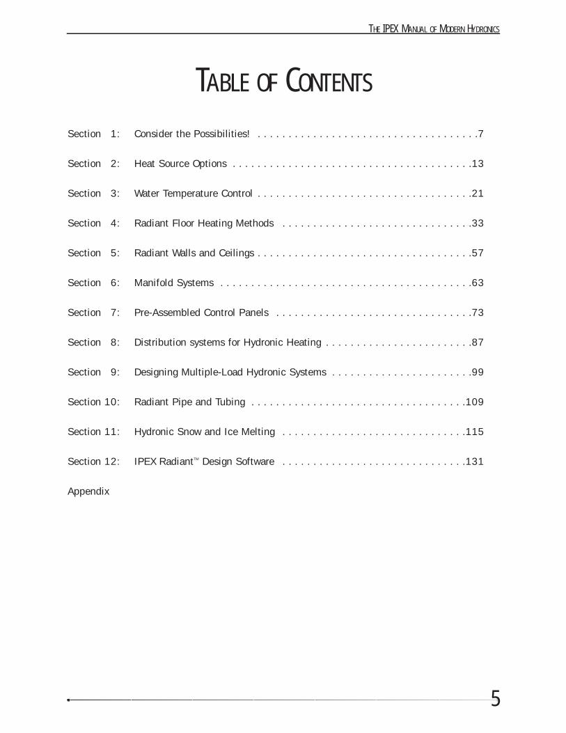
Section 1: Consider the Possibilities! . . . . . . . . . . . . . . . . . . . . . . . . . . . . . . . . . . . .7
Section 2: Heat Source Options . . . . . . . . . . . . . . . . . . . . . . . . . . . . . . . . . . . . . . .13
Section 3: Water Temperature Control . . . . . . . . . . . . . . . . . . . . . . . . . . . . . . . . . . .21
Section 4: Radiant Floor Heating Methods . . . . . . . . . . . . . . . . . . . . . . . . . . . . . . .33
Section 5: Radiant Walls and Ceilings . . . . . . . . . . . . . . . . . . . . . . . . . . . . . . . . . . .57
Section 6: Manifold Systems . . . . . . . . . . . . . . . . . . . . . . . . . . . . . . . . . . . . . . . . .63
Section 7: Pre-Assembled Control Panels . . . . . . . . . . . . . . . . . . . . . . . . . . . . . . . .73
Section 8: Distribution systems for Hydronic Heating . . . . . . . . . . . . . . . . . . . . . . . .87
Section 9: Designing Multiple-Load Hydronic Systems . . . . . . . . . . . . . . . . . . . . . . .99
Section 10: Radiant Pipe and Tubing . . . . . . . . . . . . . . . . . . . . . . . . . . . . . . . . . . .109
Section 11: Hydronic Snow and Ice Melting . . . . . . . . . . . . . . . . . . . . . . . . . . . . . .115
Section 12: IPEX RadiantTM Design Software . . . . . . . . . . . . . . . . . . . . . . . . . . . . . .131
Appendix
TABLE OF CONTENTS

SECTION
1
CONSIDER THE POSSIBILITIES!
Question:
What kinds of heating loads can be handled using modern hydronics technology?
Answer:
Almost any load you can think of!
For years the concept of hydronic heating evoked thoughts of cast-iron radiators or fin-tube baseboards in homesand commercial buildings—and not much else.
Early hydronic systems were usually classified as being “residential” or “commercial” in nature. Residentialsystems were the domain of plumbing / heating contractors. Rule of thumb design was usually good enough giventhe limited variety of systems installed. The piping and control methods used in these systems remained essen-tially unchanged between the 1950’s and the 1980’s in North America.
Commercial hydronic systems were a world apart from their residential counterparts. Techniques such as primary/ secondary piping, multiple water temperature distribution systems, and outdoor reset control were successfullydeployed in commercial systems, but almost never considered for residential applications.
A New Era for Hydronics
Times have changed considerably, hydronically speaking. Residential and commercial systems now share somecommon piping and control strategies. Successful installation strategies first developed decades ago are being“redeployed” using modern materials and control strategies that ensure decades of reliable and energy efficientoperation.
7
THE IPEX MANUAL OF MODERN HYDRONICS
8
The days when hydronic systems consisted solely ofcast-iron radiators, copper or black iron pipe and fin-tube baseboard are gone. New hardware such as Kitecpipe and WarmRite Control Panels now make itpossible to install quality systems that serve amultitude of heating loads. Modern systems can incor-porate a variety of heat emitters. Each are selected tomatch the exact thermal, aesthetic and budgetconstraints of a project.
Today, hydronic heating contractors are being asked tofurnish heating systems for everything from smallapartments to large custom-built houses, as well as avariety of commercial buildings. Each job brings itsown particular set of requirements.
Many modern systems contain several types of heatemitters operating at different water temperatures anddivided up into a dozen or more independentlycontrolled zones.
Some contractors hesitate to take on such challengingsystems. Others recognize that with the right materialsand design methods, these systems are not onlypossible, but also offer excellent profit potential as wellas the likelihood of future referrals.
Contractors who recognize what modern hydronicstechnology has to offer, and who take the time to learnhow to apply new design techniques and hardware, areenjoying unprecedented business growth.Discriminating clients seek out these hydronicspecialists because they offer what their competitioncannot—the ability to pull together modern materialsand design methods to create heating systems specifi-cally tailored to their client’s needs.
To take advantage of such opportunities, you need toknow how to use these modern piping and controltechniques. That’s what this manual is all about. It willshow you how to use Kitec pipe, WarmRite ControlPanels, and other hardware to assemble state-of-the-art hydronic systems that deliver comfort, economicaland reliable operation and most importantly, satisfiedcustomers. Armed with this knowledge you’ll findmodern hydronic heating to be among the most satis-fying and profitable niches in the HVAC industry.
IPEX Incorporated is ready, willing, and able to helpyou achieve the many benefits offered to those whoknow how to apply modern hydronics technology.
One System that Does It All
The concept that best describes modern hydronicheating is:
One heat source serving multiple loads
Those loads include:
• Radiant heating of floors, walls and ceilings• Baseboard heating• Panel radiators• Hydro-air subsystems• Indirect domestic water heating • Intermittent garage heating• Pool and spa heating• Snow melting• “District heating” of several adjacent buildings• Agricultural / horticultural loads such as
animal enclosures, greenhouse heating, and turf warming
Many projects may have several of these loads, eachrequiring heat in different amounts, at different timesand at different temperatures.
For example, the space heating loads of a givenbuilding might best be served by a combination ofhydronic heat emitters. Some areas might be perfectfor radiant floor heating while others are better suitedto radiant ceiling heating. Still other areas might beideal for baseboard or even ducted forced-air throughan air handler equipped with a hot water coil.
Almost every house and commercial building alsoneeds domestic hot water. In some cases, this load canbe as large or larger than the space heating load.
Many facilities are also perfect candidates for hydronicsnow melting - if those in charge are aware of thebenefits it offers compared to traditional methods ofsnow removal.
Some designers approach situations like these byproposing a separate, isolated hydronic system for eachload. One boiler to heat the building, another to meltthe snow in the driveway, and perhaps still another toheat the pool. The same building might also use one ormore direct-fired domestic water heaters.
Although such an approach is possible, it seldom takesadvantage of the unique ability of hydronics to connectall the loads to a single heat source. The latterapproach often reduces the size and cost of the overallsystem. It also makes for easier servicing and reducesfuel consumption. Such a synergistic system is madepossible through modern hydronics technology.
9
From Simple to Sophisticated
Let’s look at the versatility of modern hydronicstechnology in meeting the demands of both simple andsophisticated load requirements.
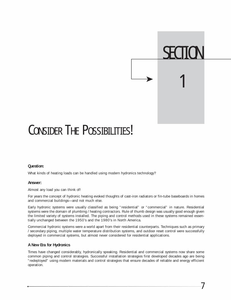
We’ll start with something basic: a floor heating systemfor a small addition to a home. Because the load issmall, a water heater will be used as the heat source.It, as well as the other system components, is shown infigure 1-1
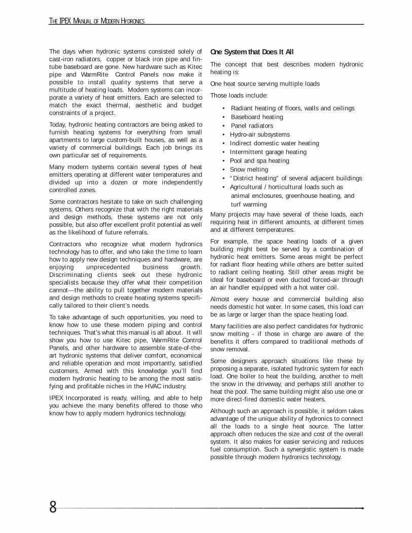
Although the installer could purchase components(such as the manifolds, a bronze circulator, expansiontank) and all the valving separately, using a WarmRitecontrol panel can save much time and labor. All theneeded components are preassembled into a compact
and easily mounted unit. All that’s left to do is to pipe
the WarmRite control panel to the water heater,connect the floor circuits, and then route power to it.
Although this system is very simple in concept andconstruction it’s also capable of delivering comfort farsuperior to its alternatives, several of which may costmore to install as well as to operate.
A Slightly Larger Requirement
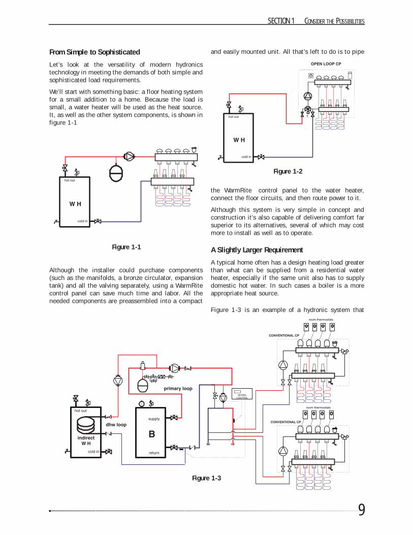
A typical home often has a design heating load greaterthan what can be supplied from a residential waterheater, especially if the same unit also has to supplydomestic hot water. In such cases a boiler is a moreappropriate heat source.
Figure 1-3 is an example of a hydronic system that
SECTION 1 CONSIDER THE POSSIBILITIES
Figure 1-1
Figure 1-2
Figure 1-3
THE IPEX MANUAL OF MODERN HYDRONICS
10
supplies space heating through a radiant floorsubsystem as well as domestic hot water via an indirectwater heater.
Two WarmRite control panels are used to provide thewater and electrical control functions for the spaceheating portion of the system. In this case, electricvalve actuators have been included in the WarmRitecontrol panels to allow individual temperature controlof several rooms. An external injection mixing systemhas been installed between the WarmRite controlpanels and the primary loop, to vary the water temper-ature supplied to the floor circuits based on outsidetemperature (e.g. outdoor reset control). This mixingsystem also protects the boiler from flue gas conden-sation that can be caused by low return water temper-atures.
Multiple Water Temperatures...No Problem
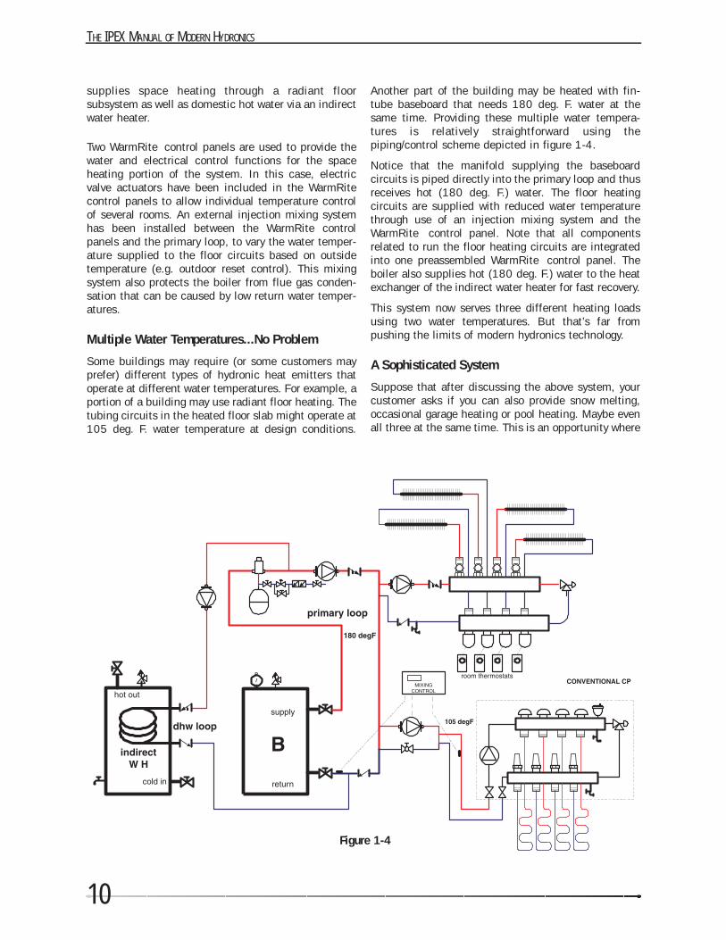
Some buildings may require (or some customers mayprefer) different types of hydronic heat emitters thatoperate at different water temperatures. For example, aportion of a building may use radiant floor heating. Thetubing circuits in the heated floor slab might operate at105 deg. F. water temperature at design conditions.
Another part of the building may be heated with fin-tube baseboard that needs 180 deg. F. water at thesame time. Providing these multiple water tempera-tures is relatively straightforward using thepiping/control scheme depicted in figure 1-4.
Notice that the manifold supplying the baseboardcircuits is piped directly into the primary loop and thusreceives hot (180 deg. F.) water. The floor heatingcircuits are supplied with reduced water temperaturethrough use of an injection mixing system and theWarmRite control panel. Note that all componentsrelated to run the floor heating circuits are integratedinto one preassembled WarmRite control panel. Theboiler also supplies hot (180 deg. F.) water to the heatexchanger of the indirect water heater for fast recovery.
This system now serves three different heating loadsusing two water temperatures. But that’s far frompushing the limits of modern hydronics technology.
A Sophisticated System
Suppose that after discussing the above system, yourcustomer asks if you can also provide snow melting,occasional garage heating or pool heating. Maybe evenall three at the same time. This is an opportunity where
Figure 1-4
11
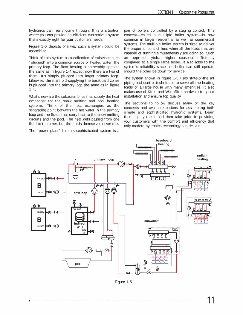
hydronics can really come through. It is a situationwhere you can provide an efficient customized systemthat’s exactly right for your customers needs.
Figure 1-5 depicts one way such a system could beassembled.
Think of this system as a collection of subassemblies“plugged” into a common source of heated water: theprimary loop. The floor heating subassembly appearsthe same as in figure 1-4 except now there are two ofthem. It’s simply plugged into larger primary loop.Likewise, the manifold supplying the baseboard zonesis plugged into the primary loop the same as in figure1-4.
What’s new are the subassemblies that supply the heatexchanger for the snow melting and pool heatingsystems. Think of the heat exchangers as theseparating point between the hot water in the primaryloop and the fluids that carry heat to the snow meltingcircuits and the pool. The heat gets passed from onefluid to the other, but the fluids themselves never mix.
The “power plant” for this sophisticated system is a
pair of boilers controlled by a staging control. Thisconcept—called a multiple boiler system—is nowcommon in larger residential as well as commercialsystems. The multiple boiler system is sized to deliverthe proper amount of heat when all the loads that arecapable of running simultaneously are doing so. Suchan approach yields higher seasonal efficiencycompared to a single large boiler. It also adds to thesystem’s reliability since one boiler can still operateshould the other be down for service.
The system shown in figure 1-5 uses state-of-the artpiping and control techniques to serve all the heatingloads of a large house with many amenities. It alsomakes use of Kitec and WarmRite hardware to speedinstallation and ensure top quality.
The sections to follow discuss many of the keyconcepts and available options for assembling bothsimple and sophisticated hydronic systems. Learnthem, apply them, and then take pride in providingyour customers with the comfort and efficiency thatonly modern hydronics technology can deliver.
SECTION 1 CONSIDER THE POSSIBILITIES
Figure 1-5

SECTION
2
HEAT SOURCE OPTIONS
A wide variety of heat sources can be used with hydronic heating systems. They include gas- and oil-fired boilers,hydronic heat pumps and domestic water heaters to name a few. Some are better suited to higher temperaturesystems, while others are ideal for low temperature systems.
This section briefly describes the characteristics of several heat sources suitable for hydronic systems. Moredetailed information pertaining to their selection and installation is best found in manufacturer’s literature andmanuals. Relevant building / mechanical codes should also be consulted for specific installation requirement.
The information at the end of this section allows designers to compare the cost of energy provided by severalcommon fuels based on their local cost and the efficiency at which they are converted to heat.
2-1 Conventional Boilers
The most common hydronic heat source is a “conventional” gas- or oil-fired boiler. They are available with heatexchangers made of cast-iron, steel and finned copper tubing.
Although designed to operate at relatively high water temperatures, conventional boilers can be adapted to lowertemperature hydronic systems such as radiant floor heating by using a mixing device. Their ability to producehigh temperature water makes them a good choice in systems where both low temperature and high temperatureheat emitters are used.
The term “conventional” describes boilers that are intended to operate without sustained condensation of the fluegases produced during the combustion process inside the boiler. These flue gases are made up of water vapor,carbon dioxide, and trace amounts of other combustion products depending on the fuels used, and the tuning ofthe burner.
All boilers experience temporary flue gas condensation during cold starts. If the boiler is connected to a low mass
13
THE IPEX MANUAL OF MODERN HYDRONICS
14
distribution system that is designed to operate athigher water temperatures—fin-tube baseboard forexample—such flue gas condensation is short-lived. Itrapidly evaporates as the boiler warms above the dewpoint of the exhaust gases.
However, when a conventional boiler serves as the heatsource for a low temperature distribution system it isimperative to keep the inlet temperature to the boilerabove the dew point of the exhaust gases. For gas-firedboilers, the inlet water temperature during sustainedoperation should not be less than 130 deg. F. For oil-fired boilers, it should not be less than 150 deg. F.
Failure to provide such boiler inlet temperatureprotection will cause the water vapor (and othercompounds present in the exhaust gases) to contin-ually condense on the internal heat exchangersurfaces. The acidic nature of such condensate cancause swift and severe corrosion along with scaleformation inside the boiler. It can also rapidly corrodegalvanized vent piping, as well as the deterioration ofmasonry chimneys
Hydronic distribution systems with high thermal masscan also cause prolonged flue gas condensation as thesystem warms up to normal operating temperature. Acool concrete slab with embedded tubing circuits is agood example. As the slab begins to warm, its thermalmass can extract heat from the circulating waterstream 3 to 4 times faster than normal. Since the rateof heat release from the water is much higher than therate of heat production, the water temperature (in anunprotected boiler) will quickly drop well below thedew point temperature of the exhaust gases. The boilercan operate for hours with sustained flue gas conden-sation. Such a situation must be avoided.
The key to avoiding low boiler inlet water temperatureis preventing the distribution system—whatever type ithappens to be—from extracting heat from the waterfaster than the boiler can produce heat.
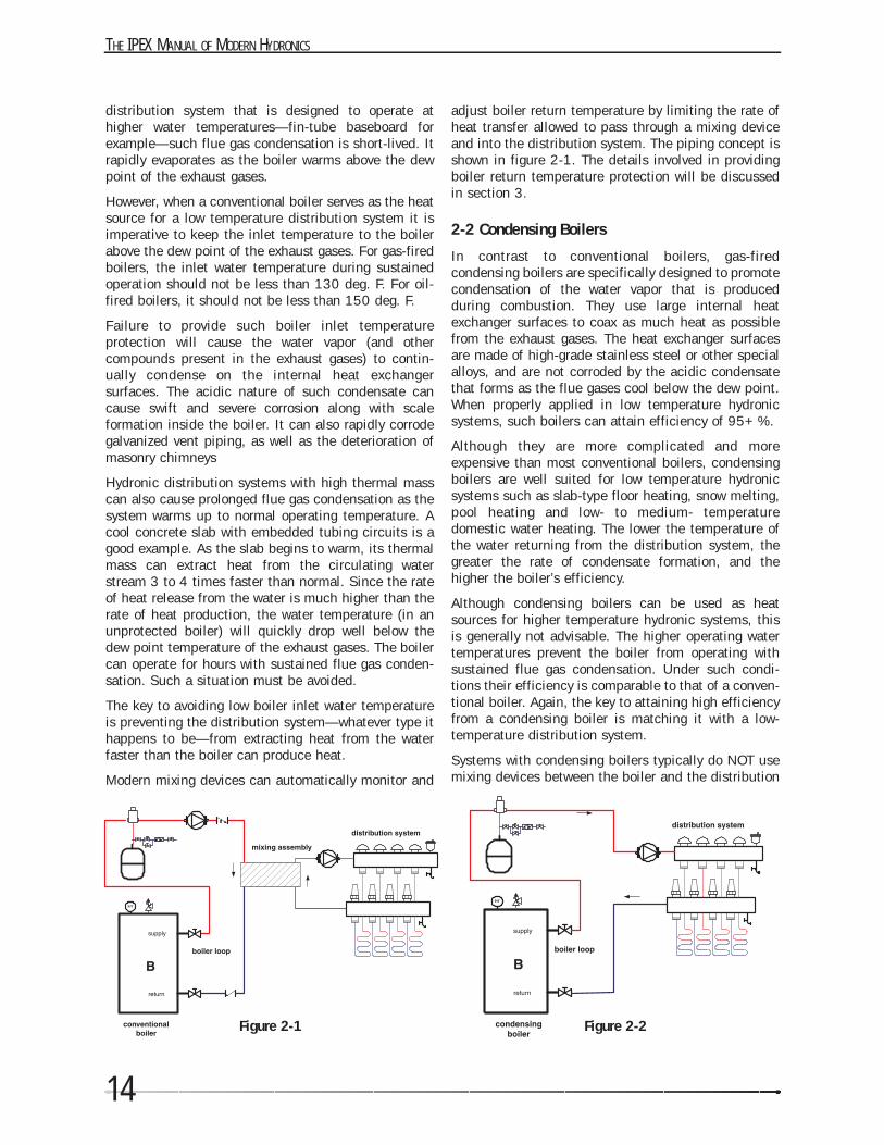
Modern mixing devices can automatically monitor and
adjust boiler return temperature by limiting the rate ofheat transfer allowed to pass through a mixing deviceand into the distribution system. The piping concept isshown in figure 2-1. The details involved in providingboiler return temperature protection will be discussedin section 3.
2-2 Condensing Boilers
In contrast to conventional boilers, gas-firedcondensing boilers are specifically designed to promotecondensation of the water vapor that is producedduring combustion. They use large internal heatexchanger surfaces to coax as much heat as possiblefrom the exhaust gases. The heat exchanger surfacesare made of high-grade stainless steel or other specialalloys, and are not corroded by the acidic condensatethat forms as the flue gases cool below the dew point.When properly applied in low temperature hydronicsystems, such boilers can attain efficiency of 95+ %.
Although they are more complicated and moreexpensive than most conventional boilers, condensingboilers are well suited for low temperature hydronicsystems such as slab-type floor heating, snow melting,pool heating and low- to medium- temperaturedomestic water heating. The lower the temperature ofthe water returning from the distribution system, thegreater the rate of condensate formation, and thehigher the boiler’s efficiency.
Although condensing boilers can be used as heatsources for higher temperature hydronic systems, thisis generally not advisable. The higher operating watertemperatures prevent the boiler from operating withsustained flue gas condensation. Under such condi-tions their efficiency is comparable to that of a conven-tional boiler. Again, the key to attaining high efficiencyfrom a condensing boiler is matching it with a low-temperature distribution system.
Systems with condensing boilers typically do NOT usemixing devices between the boiler and the distribution
Figure 2-1 Figure 2-2
15
system. This helps offset a portion of the boiler’s highercost. Most condensing boilers can also be side wallvented through a 2” CPVC pipe. This too lowers instal-lation cost relative to boilers vented through a chimney.Figure 2-2 shows how a condensing boiler would bepiped in a typical floor heating system.
2-3 Tank-type Water Heaters
Some hydronic systems can use tank-type domesticwater heaters as their heat source. Usually the size ofsuch systems is limited by the heating capacity of thewater heater. Residential water heaters have heatoutputs in the range of 15,000 to 40,000 Btu/hr. Thisusually limits their application to small apartments ormodest residential additions.
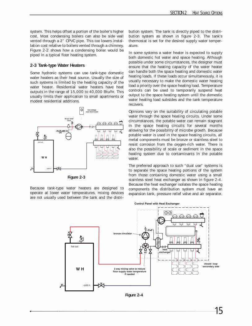
Because tank-type water heaters are designed tooperate at lower water temperatures, mixing devicesare not usually used between the tank and the distri-
bution system. The tank is directly piped to the distri-bution system as shown in figure 2-3. The tank’sthermostat is set for the desired supply water temper-ature.
In some systems a water heater is expected to supplyboth domestic hot water and space heating. Althoughpossible under some circumstances, the designer mustensure that the heating capacity of the water heatercan handle both the space heating and domestic waterheating loads. If these loads occur simultaneously, it isusually necessary to make the domestic water heatingload a priority over the space heating load. Temperaturecontrols can be used to temporarily suspend heatoutput to the space heating system until the domesticwater heating load subsides and the tank temperaturerecovers.
Opinions vary on the suitability of circulating potablewater through the space heating circuits. Under somecircumstances, the potable water can remain stagnantin the space heating circuits for several monthsallowing for the possibility of microbe growth. Becausepotable water is used in the space heating circuits, allmetal components must be bronze or stainless steel toresist corrosion from the oxygen-rich water. There isalso the possibility of scale or sediment in the spaceheating system due to contaminants in the potablewater.
The preferred approach to such “dual use” systems isto separate the space heating portions of the systemfrom those containing domestic water using a smallstainless steel heat exchanger as shown in figure 2-4.Because the heat exchanger isolates the space heatingcomponents the distribution system must have anexpansion tank, pressure relief valve and air separator.
SECTION 2 HEAT SOURCE OPTIONS
Figure 2-3
Figure 2-4
THE IPEX MANUAL OF MODERN HYDRONICS
16
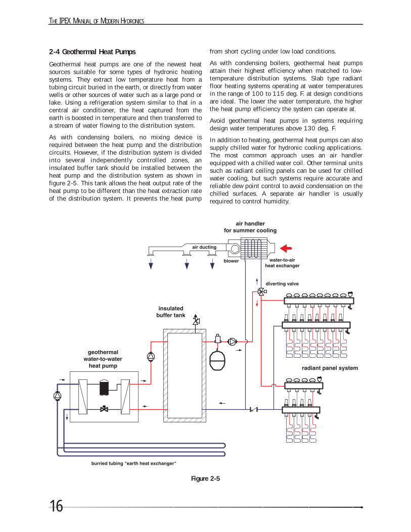
2-4 Geothermal Heat Pumps
Geothermal heat pumps are one of the newest heatsources suitable for some types of hydronic heatingsystems. They extract low temperature heat from atubing circuit buried in the earth, or directly from waterwells or other sources of water such as a large pond orlake. Using a refrigeration system similar to that in acentral air conditioner, the heat captured from theearth is boosted in temperature and then transferred toa stream of water flowing to the distribution system.
As with condensing boilers, no mixing device isrequired between the heat pump and the distributioncircuits. However, if the distribution system is dividedinto several independently controlled zones, aninsulated buffer tank should be installed between theheat pump and the distribution system as shown infigure 2-5. This tank allows the heat output rate of theheat pump to be different than the heat extraction rateof the distribution system. It prevents the heat pump
from short cycling under low load conditions.
As with condensing boilers, geothermal heat pumpsattain their highest efficiency when matched to low-temperature distribution systems. Slab type radiantfloor heating systems operating at water temperaturesin the range of 100 to 115 deg. F. at design conditionsare ideal. The lower the water temperature, the higherthe heat pump efficiency the system can operate at.
Avoid geothermal heat pumps in systems requiringdesign water temperatures above 130 deg. F.
In addition to heating, geothermal heat pumps can alsosupply chilled water for hydronic cooling applications.The most common approach uses an air handlerequipped with a chilled water coil. Other terminal unitssuch as radiant ceiling panels can be used for chilledwater cooling, but such systems require accurate andreliable dew point control to avoid condensation on thechilled surfaces. A separate air handler is usuallyrequired to control humidity.
Figure 2-5
17
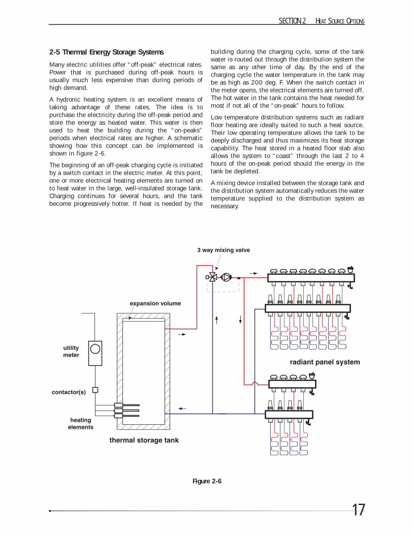
2-5 Thermal Energy Storage Systems
Many electric utilities offer “off-peak” electrical rates.Power that is purchased during off-peak hours isusually much less expensive than during periods ofhigh demand.
A hydronic heating system is an excellent means oftaking advantage of these rates. The idea is topurchase the electricity during the off-peak period andstore the energy as heated water. This water is thenused to heat the building during the “on-peaks”periods when electrical rates are higher. A schematicshowing how this concept can be implemented isshown in figure 2-6.
The beginning of an off-peak charging cycle is initiatedby a switch contact in the electric meter. At this point,one or more electrical heating elements are turned onto heat water in the large, well-insulated storage tank.Charging continues for several hours, and the tankbecome progressively hotter. If heat is needed by the
building during the charging cycle, some of the tankwater is routed out through the distribution system thesame as any other time of day. By the end of thecharging cycle the water temperature in the tank maybe as high as 200 deg. F. When the switch contact inthe meter opens, the electrical elements are turned off.The hot water in the tank contains the heat needed formost if not all of the “on-peak” hours to follow.
Low temperature distribution systems such as radiantfloor heating are ideally suited to such a heat source.Their low operating temperature allows the tank to bedeeply discharged and thus maximizes its heat storagecapability. The heat stored in a heated floor slab alsoallows the system to “coast” through the last 2 to 4hours of the on-peak period should the energy in thetank be depleted.
A mixing device installed between the storage tank andthe distribution system automatically reduces the watertemperature supplied to the distribution system asnecessary.
SECTION 2 HEAT SOURCE OPTIONS
Figure 2-6
THE IPEX MANUAL OF MODERN HYDRONICS
18
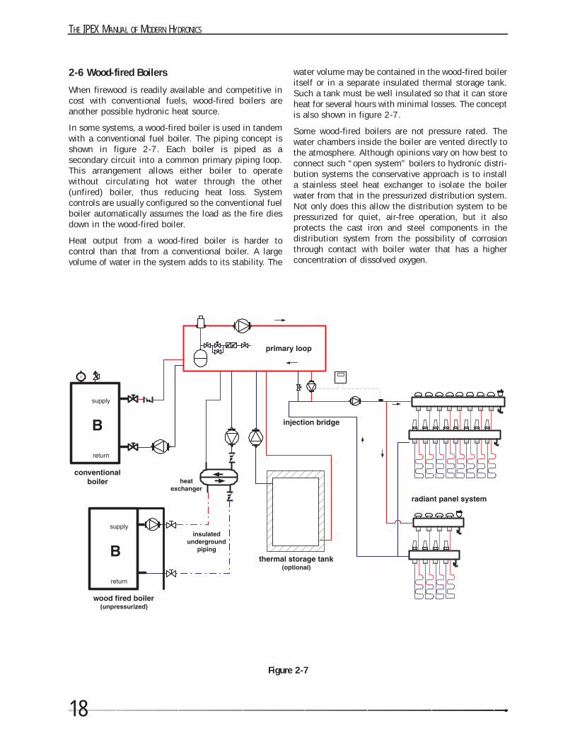
2-6 Wood-fired Boilers
When firewood is readily available and competitive incost with conventional fuels, wood-fired boilers areanother possible hydronic heat source.
In some systems, a wood-fired boiler is used in tandemwith a conventional fuel boiler. The piping concept isshown in figure 2-7. Each boiler is piped as asecondary circuit into a common primary piping loop.This arrangement allows either boiler to operatewithout circulating hot water through the other(unfired) boiler, thus reducing heat loss. Systemcontrols are usually configured so the conventional fuelboiler automatically assumes the load as the fire diesdown in the wood-fired boiler.
Heat output from a wood-fired boiler is harder tocontrol than that from a conventional boiler. A largevolume of water in the system adds to its stability. The
water volume may be contained in the wood-fired boileritself or in a separate insulated thermal storage tank.Such a tank must be well insulated so that it can storeheat for several hours with minimal losses. The conceptis also shown in figure 2-7.
Some wood-fired boilers are not pressure rated. Thewater chambers inside the boiler are vented directly tothe atmosphere. Although opinions vary on how best toconnect such “open system” boilers to hydronic distri-bution systems the conservative approach is to installa stainless steel heat exchanger to isolate the boilerwater from that in the pressurized distribution system.Not only does this allow the distribution system to bepressurized for quiet, air-free operation, but it alsoprotects the cast iron and steel components in thedistribution system from the possibility of corrosionthrough contact with boiler water that has a higherconcentration of dissolved oxygen.
Figure 2-7

19
SECTION 2 HEAT SOURCE OPTIONS
2-7 Comparing Fuel Costs
In many cases the heat source is selected based on thetype of fuel that is available or determined to be mosteconomical over the life of the system. The commonlyused fuels are sold in different units such as kilowatt-hours for electricity, therms for natural gas, gallons forfuel oil and face cords for firewood. To perform anaccurate comparison it is necessary to express the costand energy content of each candidate fuel on a
common basis.
The formulas in figure 2-8 allow the cost of heatingenergy from each of several fuels to be expressed onthe common basis of dollars per million Btu’s ofdelivered heat. This is abbreviated as $/MMBtu. Theseformulas take into account the cost, purchase units, aswell as efficiency of the heat source in converting thefuel into useful heat.
Figure 2-8

SECTION
3
WATER TEMPERATURE CONTROL
All hydronic heating systems must control the water temperature supplied to their heat emitters. A simple systemmay only need to supply one water temperature to all the loads it serves. A more sophisticated system containingseveral types of heat emitters may need to simultaneously supply two or more water temperatures.
This section discusses several methods of water temperature control and the hardware necessary to accomplish it.
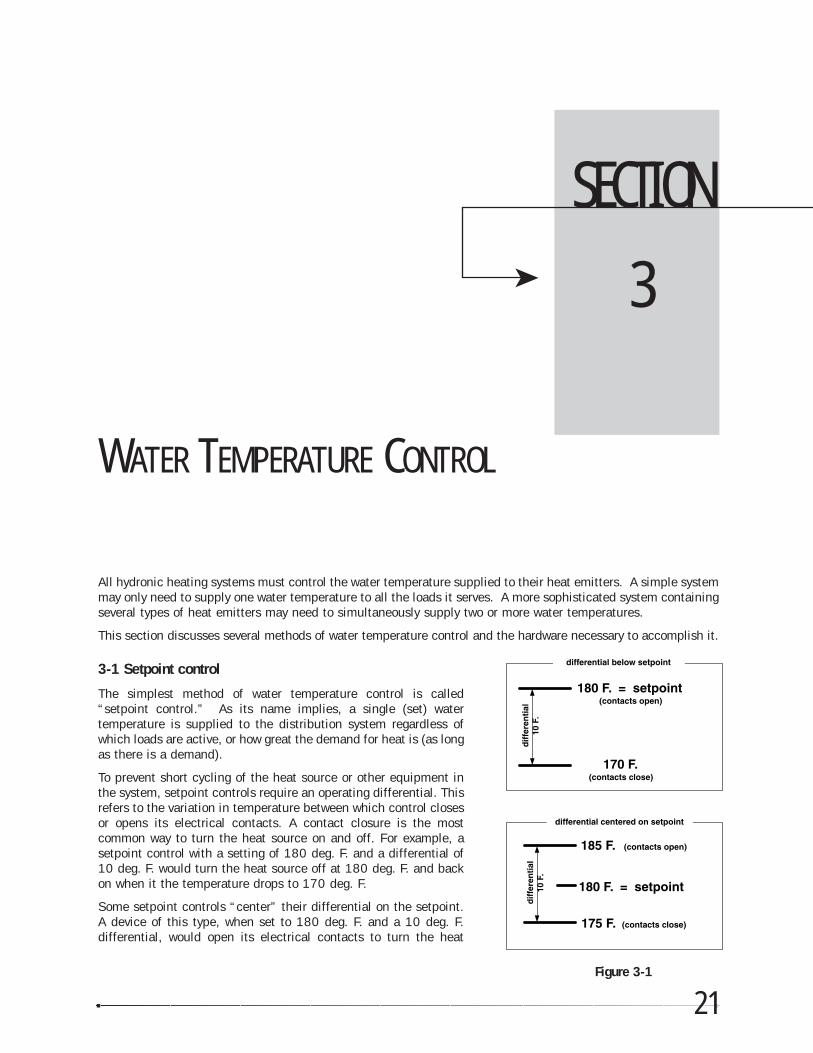
3-1 Setpoint control
The simplest method of water temperature control is called“setpoint control.” As its name implies, a single (set) watertemperature is supplied to the distribution system regardless ofwhich loads are active, or how great the demand for heat is (as longas there is a demand).
To prevent short cycling of the heat source or other equipment inthe system, setpoint controls require an operating differential. Thisrefers to the variation in temperature between which control closesor opens its electrical contacts. A contact closure is the mostcommon way to turn the heat source on and off. For example, asetpoint control with a setting of 180 deg. F. and a differential of10 deg. F. would turn the heat source off at 180 deg. F. and backon when it the temperature drops to 170 deg. F.
Some setpoint controls “center” their differential on the setpoint.A device of this type, when set to 180 deg. F. and a 10 deg. F.differential, would open its electrical contacts to turn the heat
21Figure 3-1
THE IPEX MANUAL OF MODERN HYDRONICS
22
source off at 185 deg. F. and close them when thesensed temperature drops to 175 deg. F. Figure 3-1compares these two types of setpoint control.
Some setpoint controls have fixed (non-adjustable)differentials, while others provide an adjustable differ-ential. The narrower the differential, the closer thewater temperature stays to the desired setpoint.However if the differential is too narrow, the heatsource or other equipment in the system couldexperience excessively short operating cycles thatreduce their efficiency and shorten their life. Heatsource operating differentials in the range of 10 deg. F.are common in hydronic systems.
Systems using setpoint controls provide the sameaverage water temperature to the loads whenever thereis a call for heat, regardless of the rate of heat inputrequired by the load. For example, a boiler operated bya setpoint control supplying a circuit of fin-tubebaseboard would deliver hot water (perhaps averagingaround 175 deg. F.) whether the outdoor temperaturewas -10 deg. F. on a cold January night, or 50 deg. F.on a mild October afternoon. To prevent overheatingunder all but design load conditions, flow must beperiodically interrupted by turning off the circulator orclosing the zone valves. To keep room temperaturevariations to a minimum, it’s important to have athermostat with a narrow differential of perhaps 1 or 2deg. F. If the thermostat has an anticipator it should becarefully set for the electrical current flow through itduring its on-cycle.
3-2 Outdoor reset control
Rather than deliver heat in “spurts,” an ideal systemwould continually adjust its rate of heat delivery tomatch the heat loss of the building. The indoor airtemperature would remain constant, and there wouldbe no difference in comfort regardless of outside condi-tions.
Outdoor reset control (ORC) was developed for thispurpose. It enables heat to flow from the heat emittersto the space being heated at just the right rate. ORC isincreasingly recognized as the preferred method ofwater temperature control, especially for high thermalmass floor heating systems.
All outdoor reset controls use outside air temperatureto determine the ideal “target” water temperature to besupplied to the system’s heat emitters. The colder it isoutside, the higher the water temperature. The goal isto match the rate of heat delivery to the rate of heatloss from the building.
There are two methods of using reset control in ahydronic system. Each can be used by itself, or the twocan be used in combination.
They are:
1. boiler reset control
2. mixing reset control
A boiler reset control takes over operation of the burnerfrom the standard (fixed) high limit control suppliedwith most boilers. As the outside air temperaturechanges, the reset control continually recalculates howhigh the boiler water temperature will be allowed toclimb and operates the burner accordingly.
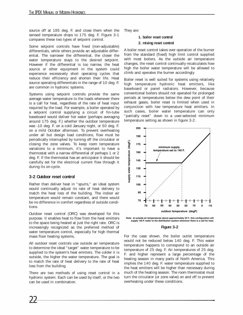
Boiler reset is well suited for systems using relativelyhigh temperature hydronic heat emitters, likebaseboard or panel radiators. However, becauseconventional boilers should not operated for prolongedperiods at temperatures below the dew point of theirexhaust gases, boiler reset is limited when used inconjunction with low temperature heat emitters. Insuch cases, boiler water temperature can only“partially reset” down to a user-selected minimumtemperature setting as shown in figure 3-2.
For the case shown, the boiler outlet temperaturewould not be reduced below 140 deg. F. This watertemperature happens to correspond to an outside airtemperature of 25 deg. F. Air temperatures of 25 deg.F. and higher represent a large percentage of theheating season in many parts of North America. Thisimplies the 140 deg. F. water temperature supplied tothe heat emitters will be higher than necessary duringmuch of the heating season. The room thermostat mustturn the circulator (or zone valve) on and off to preventoverheating under these conditions.
Figure 3-2
23
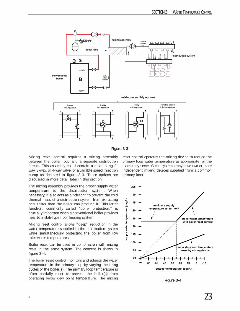
Mixing reset control requires a mixing assemblybetween the boiler loop and a separate distributioncircuit. This assembly could contain a modulating 2-way, 3-way, or 4-way valve, or a variable speed injectionpump as depicted in figure 3-3. These options arediscussed in more detail later in this section.
The mixing assembly provides the proper supply watertemperature to the distribution system. Whennecessary, it also acts as a “clutch” to prevent the coldthermal mass of a distribution system from extractingheat faster than the boiler can produce it. This latterfunction, commonly called “boiler protection,” iscrucially important when a conventional boiler providesheat to a slab-type floor heating system.
Mixing reset control allows “deep” reduction in thewater temperature supplied to the distribution systemwhile simultaneously protecting the boiler from lowinlet water temperatures.
Boiler reset can be used in combination with mixingreset in the same system. The concept is shown infigure 3-4.
The boiler reset control monitors and adjusts the watertemperature in the primary loop by varying the firingcycles of the boiler(s). The primary loop temperature isoften partially reset to prevent the boiler(s) fromoperating below dew point temperature. The mixing
reset control operates the mixing device to reduce theprimary loop water temperature as appropriate for theloads they serve. Some systems may have two or moreindependent mixing devices supplied from a commonprimary loop.
SECTION 3 WATER TEMPERATURE CONTROL
Figure 3-3
Figure 3-4
THE IPEX MANUAL OF MODERN HYDRONICS
24
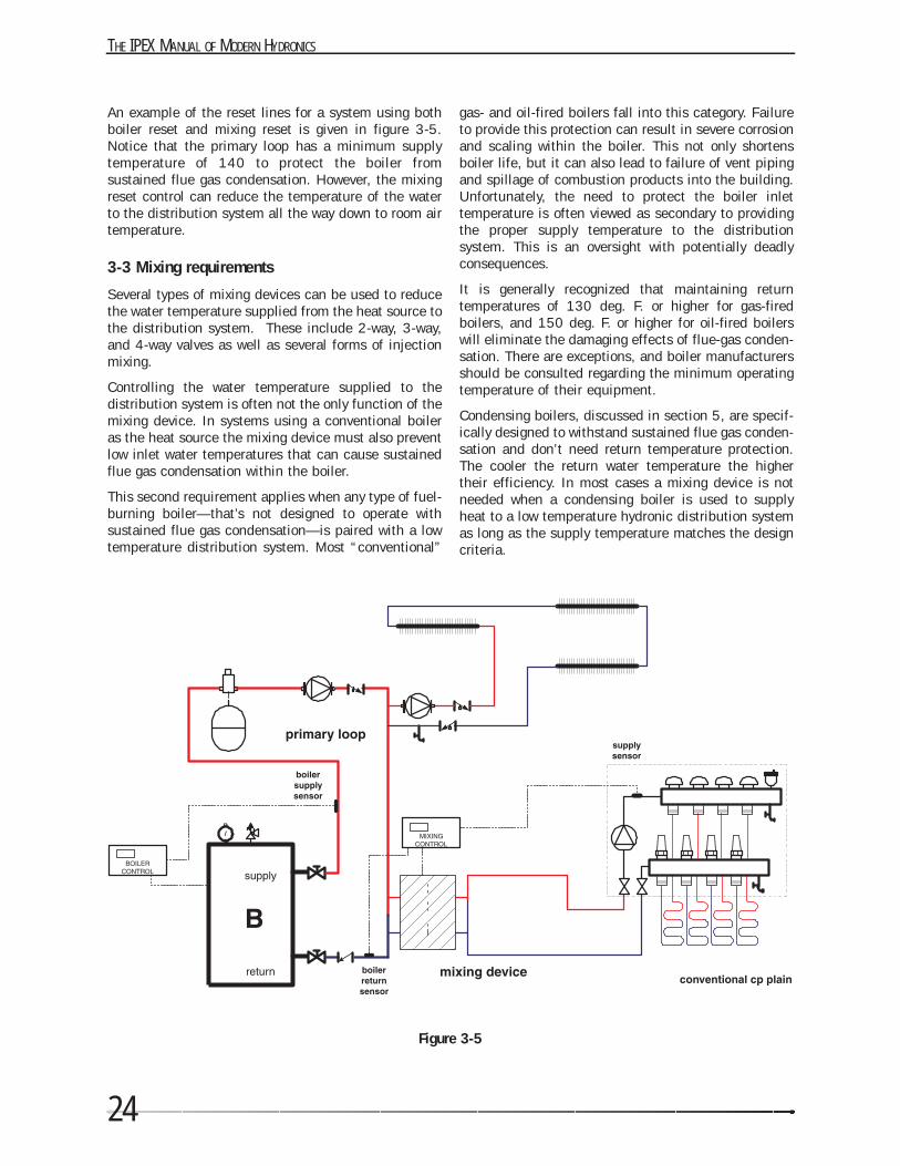
An example of the reset lines for a system using bothboiler reset and mixing reset is given in figure 3-5.Notice that the primary loop has a minimum supplytemperature of 140 to protect the boiler fromsustained flue gas condensation. However, the mixingreset control can reduce the temperature of the waterto the distribution system all the way down to room airtemperature.
3-3 Mixing requirements
Several types of mixing devices can be used to reducethe water temperature supplied from the heat source tothe distribution system. These include 2-way, 3-way,and 4-way valves as well as several forms of injectionmixing.
Controlling the water temperature supplied to thedistribution system is often not the only function of themixing device. In systems using a conventional boileras the heat source the mixing device must also preventlow inlet water temperatures that can cause sustainedflue gas condensation within the boiler.
This second requirement applies when any type of fuel-burning boiler—that’s not designed to operate withsustained flue gas condensation—is paired with a lowtemperature distribution system. Most “conventional”
gas- and oil-fired boilers fall into this category. Failureto provide this protection can result in severe corrosionand scaling within the boiler. This not only shortensboiler life, but it can also lead to failure of vent pipingand spillage of combustion products into the building.Unfortunately, the need to protect the boiler inlettemperature is often viewed as secondary to providingthe proper supply temperature to the distributionsystem. This is an oversight with potentially deadlyconsequences.
It is generally recognized that maintaining returntemperatures of 130 deg. F. or higher for gas-firedboilers, and 150 deg. F. or higher for oil-fired boilerswill eliminate the damaging effects of flue-gas conden-sation. There are exceptions, and boiler manufacturersshould be consulted regarding the minimum operatingtemperature of their equipment.
Condensing boilers, discussed in section 5, are specif-ically designed to withstand sustained flue gas conden-sation and don’t need return temperature protection.The cooler the return water temperature the highertheir efficiency. In most cases a mixing device is notneeded when a condensing boiler is used to supplyheat to a low temperature hydronic distribution systemas long as the supply temperature matches the designcriteria.
Figure 3-5
25
Hydronic heat sources that don’t produce flue gasesdon’t need to be protected against flue gas conden-sation. These include electric boilers, hydronic heatpumps, thermal storage tanks, and heat exchangers.
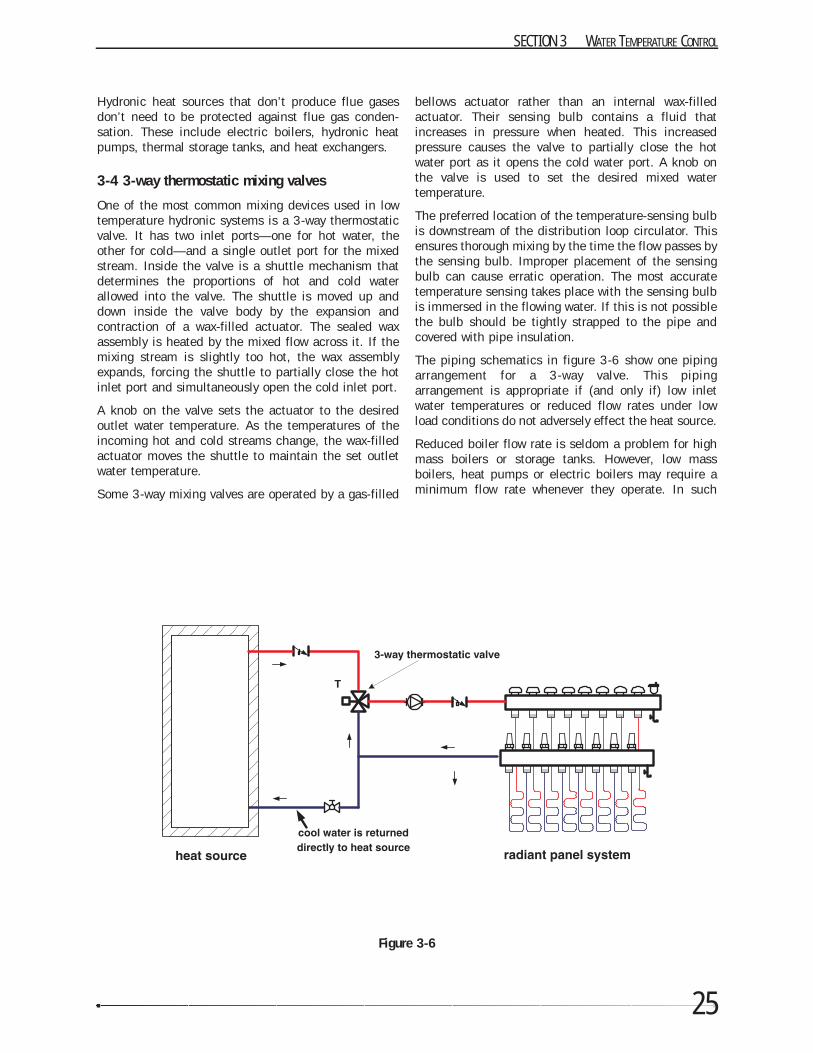
3-4 3-way thermostatic mixing valves
One of the most common mixing devices used in lowtemperature hydronic systems is a 3-way thermostaticvalve. It has two inlet ports—one for hot water, theother for cold—and a single outlet port for the mixedstream. Inside the valve is a shuttle mechanism thatdetermines the proportions of hot and cold waterallowed into the valve. The shuttle is moved up anddown inside the valve body by the expansion andcontraction of a wax-filled actuator. The sealed waxassembly is heated by the mixed flow across it. If themixing stream is slightly too hot, the wax assemblyexpands, forcing the shuttle to partially close the hotinlet port and simultaneously open the cold inlet port.
A knob on the valve sets the actuator to the desiredoutlet water temperature. As the temperatures of theincoming hot and cold streams change, the wax-filledactuator moves the shuttle to maintain the set outletwater temperature.
Some 3-way mixing valves are operated by a gas-filled
bellows actuator rather than an internal wax-filledactuator. Their sensing bulb contains a fluid thatincreases in pressure when heated. This increasedpressure causes the valve to partially close the hotwater port as it opens the cold water port. A knob onthe valve is used to set the desired mixed watertemperature.
The preferred location of the temperature-sensing bulbis downstream of the distribution loop circulator. Thisensures thorough mixing by the time the flow passes bythe sensing bulb. Improper placement of the sensingbulb can cause erratic operation. The most accuratetemperature sensing takes place with the sensing bulbis immersed in the flowing water. If this is not possiblethe bulb should be tightly strapped to the pipe andcovered with pipe insulation.
The piping schematics in figure 3-6 show one pipingarrangement for a 3-way valve. This pipingarrangement is appropriate if (and only if) low inletwater temperatures or reduced flow rates under lowload conditions do not adversely effect the heat source.
Reduced boiler flow rate is seldom a problem for highmass boilers or storage tanks. However, low massboilers, heat pumps or electric boilers may require aminimum flow rate whenever they operate. In such
SECTION 3 WATER TEMPERATURE CONTROL
Figure 3-6
THE IPEX MANUAL OF MODERN HYDRONICS
26
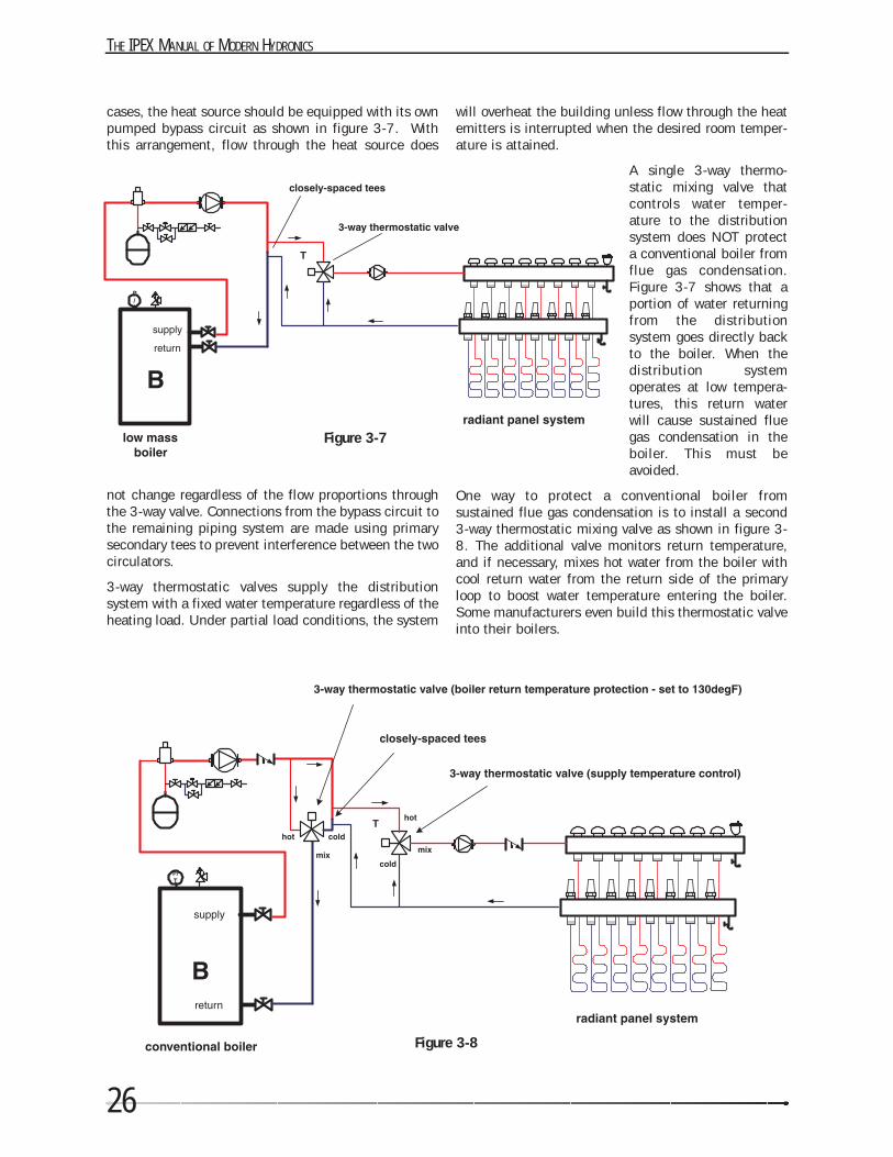
cases, the heat source should be equipped with its ownpumped bypass circuit as shown in figure 3-7. Withthis arrangement, flow through the heat source does
not change regardless of the flow proportions throughthe 3-way valve. Connections from the bypass circuit tothe remaining piping system are made using primarysecondary tees to prevent interference between the twocirculators.
3-way thermostatic valves supply the distributionsystem with a fixed water temperature regardless of theheating load. Under partial load conditions, the system
will overheat the building unless flow through the heatemitters is interrupted when the desired room temper-ature is attained.
A single 3-way thermo-static mixing valve thatcontrols water temper-ature to the distributionsystem does NOT protecta conventional boiler fromflue gas condensation.Figure 3-7 shows that aportion of water returningfrom the distributionsystem goes directly backto the boiler. When thedistribution systemoperates at low tempera-tures, this return waterwill cause sustained fluegas condensation in theboiler. This must beavoided.
One way to protect a conventional boiler fromsustained flue gas condensation is to install a second3-way thermostatic mixing valve as shown in figure 3-8. The additional valve monitors return temperature,and if necessary, mixes hot water from the boiler withcool return water from the return side of the primaryloop to boost water temperature entering the boiler.Some manufacturers even build this thermostatic valveinto their boilers.
Figure 3-8
Figure 3-7
27
3-5 3-way motorized mixing valves
3-way valve bodies can also be paired with precisionmotorized actuators. An electronic controller regulatessuch actuators. The resulting motorized valve systemcan supply either fixed or variable water temperaturesto a radiant panel.
The valve body used for this type of mixing system isoften different from that used for a 3-way thermostaticvalve. It has a rotating (as opposed to linear motion)shaft. As the shaft rotates through approximately 90degrees of arc, the internal spool simultaneously opensone inlet port and closes the other. This regulates theproportions of hot and cold water entering the valve,and thus determines the mixed outlet temperature.
The actuating motor turns the valve shaft very slowly.Rotating the shaft through 90 degrees of arc may take2 to 3 minutes. This slow rotation is not a problemgiven the slow response of many high mass distributionsystems. It actually helps stabilize the system againstovershooting or undershooting the target water temper-ature.
A temperature sensor attached to the piping leading tothe distribution system measures the mixed watertemperature leaving the valve. It provides feedback toan electronic controller that regulates the valve motor.If the temperature is exactly where it should be, themotor does not change the valve’s stem position. If thesupply temperature is slightly low, the motor veryslowly rotates the valve stem to allow more hot water to
enter the mix and vice versa. Since the sensor isdownstream of the valve’s outlet port, it providesconstant feedback to the controller allowing it to finetune water temperature.
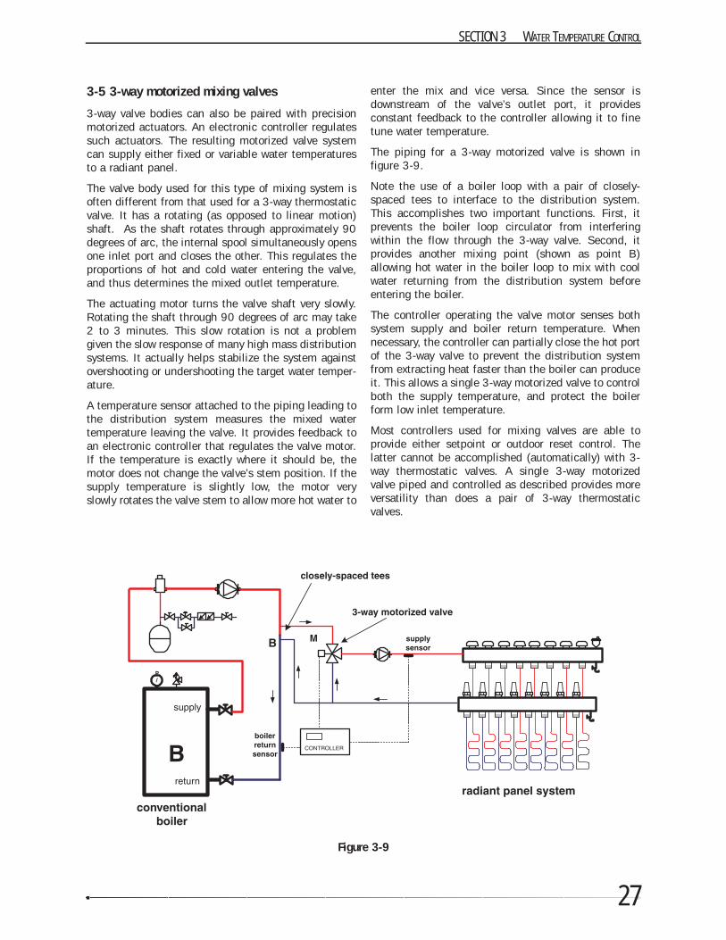
The piping for a 3-way motorized valve is shown infigure 3-9.
Note the use of a boiler loop with a pair of closely-spaced tees to interface to the distribution system.This accomplishes two important functions. First, itprevents the boiler loop circulator from interferingwithin the flow through the 3-way valve. Second, itprovides another mixing point (shown as point B)allowing hot water in the boiler loop to mix with coolwater returning from the distribution system beforeentering the boiler.
The controller operating the valve motor senses bothsystem supply and boiler return temperature. Whennecessary, the controller can partially close the hot portof the 3-way valve to prevent the distribution systemfrom extracting heat faster than the boiler can produceit. This allows a single 3-way motorized valve to controlboth the supply temperature, and protect the boilerform low inlet temperature.
Most controllers used for mixing valves are able toprovide either setpoint or outdoor reset control. Thelatter cannot be accomplished (automatically) with 3-way thermostatic valves. A single 3-way motorizedvalve piped and controlled as described provides moreversatility than does a pair of 3-way thermostaticvalves.
SECTION 3 WATER TEMPERATURE CONTROL
Figure 3-9
THE IPEX MANUAL OF MODERN HYDRONICS
28
3-6 4-way motorized mixing valves
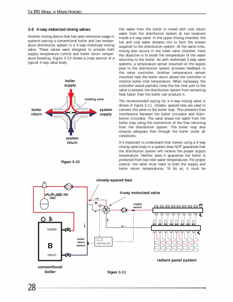
Another mixing device that has seen extensive usage insystems pairing a conventional boiler and low temper-ature distribution system is a 4-way motorized mixingvalve. These valves were designed to provide bothsupply temperature control and boiler return temper-ature boosting. Figure 3-10 shows a cross section of atypical 4-way valve body.
Hot water from the boiler is mixed with cool returnwater from the distribution system at two locationsinside a 4-way valve. In the upper mixing chamber, thehot and cool water streams mix to form the streamsupplied to the distribution system. At the same time,mixing also occurs in the lower valve chamber. Herethe objective is to boost the temperature of the waterreturning to the boiler. As with motorized 3-way valvesystems, a temperature sensor mounted on the supplypipe to the distribution system provides feedback tothe valve controller. Another temperature sensormounted near the boiler return allows the controller tomonitor boiler inlet temperature. When necessary, thecontroller would partially close the hot inlet port to thevalve to prevent the distribution system from extractingheat faster than the boiler can produce it.
The recommended piping for a 4-way mixing valve isshown in figure 3-11. Closely- spaced tees are used toconnect the valve to the boiler loop. This prevents flowinterference between the boiler circulator and distri-bution circulator. The valve draws hot water from theboiler loop using the momentum of the flow returningfrom the distribution system. The boiler loop alsoensures adequate flow through the boiler under allconditions.
It’s important to understand that merely using a 4-waymixing valve body in a system does NOT guarantee thatthe distribution system will receive the proper supplytemperature. Neither does it guarantee the boiler isprotected from low inlet water temperatures. For propercontrol, the valve must react to both the supply andboiler return temperatures. To do so, it must be
Figure 3-11
Figure 3-10
29
directed by a controller that senses both supply andreturn temperature. It’s pointless to install a 4-wayvalve body while omitting the actuator / controller itneeds for proper operation.
3-7 Injection Mixing (the concept)
Injection mixing is one of the simplest yet mostversatile methods of controlling the water temperaturein a hydronic distribution system. The concept isshown in figure 3-12.
Hot water from the boiler loop is pushed through a pipecalled an injection riser. It enters the side port of a teeat point (A) where it mixes with cool water returningfrom the distribution system. The blending of these twostreams determines the supply temperature to thesecondary circuit. The greater the flow rate of hot waterentering the tee, the warmer the distribution systemgets and the greater its heat output.
Injection mixing is ideal for systems pairing a conven-tional boiler to a low temperature distribution system.The large temperature difference (∆T) between theincoming hot water and the outgoing return waterallows a high rate of heat transfer using a minimalinjection flow rate.
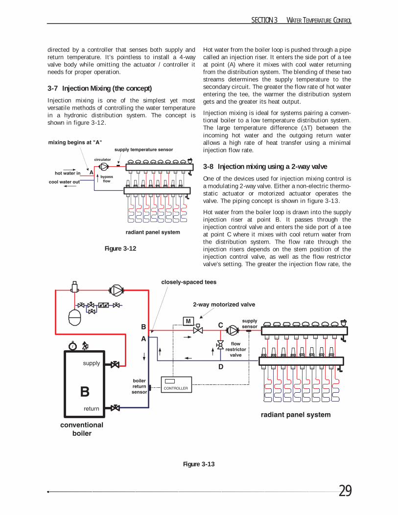
3-8 Injection mixing using a 2-way valve
One of the devices used for injection mixing control isa modulating 2-way valve. Either a non-electric thermo-static actuator or motorized actuator operates thevalve. The piping concept is shown in figure 3-13.
Hot water from the boiler loop is drawn into the supplyinjection riser at point B. It passes through theinjection control valve and enters the side port of a teeat point C where it mixes with cool return water fromthe distribution system. The flow rate through theinjection risers depends on the stem position of theinjection control valve, as well as the flow restrictorvalve’s setting. The greater the injection flow rate, the
SECTION 3 WATER TEMPERATURE CONTROL
Figure 3-13
Figure 3-12
THE IPEX MANUAL OF MODERN HYDRONICS
30
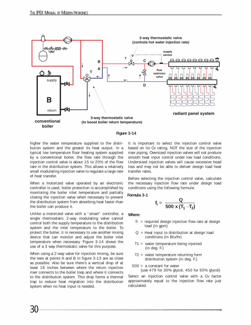
higher the water temperature supplied to the distri-bution system and the greater its heat output. In atypical low temperature floor heating system suppliedby a conventional boiler, the flow rate through theinjection control valve is about 15 to 20% of the flowrate in the distribution system. This allows a relativelysmall modulating injection valve to regulate a large rateof heat transfer.
When a motorized valve operated by an electroniccontroller is used, boiler protection is accomplished bymonitoring the boiler inlet temperature and partiallyclosing the injection valve when necessary to preventthe distribution system from absorbing heat faster thanthe boiler can produce it.
Unlike a motorized valve with a “smart” controller, asingle thermostatic 2-way modulating valve cannotcontrol both the supply temperature to the distributionsystem and the inlet temperature to the boiler. Toprotect the boiler, it is necessary to use another mixingdevice that can monitor and adjust the boiler inlettemperature when necessary. Figure 3-14 shows theuse of a 3 way thermostatic valve for this purpose.
When using a 2-way valve for injection mixing, be surethe tees at points A and B in figure 3-13 are as closeas possible. Also be sure there’s a vertical drop of atleast 18 inches between where the return injectionriser connects to the boiler loop and where it connectsto the distribution system. This drop forms a thermaltrap to reduce heat migration into the distributionsystem when no heat input is needed.
It is important to select the injection control valvebased on its Cv rating, NOT the size of the injectionriser piping. Oversized injection valves will not producesmooth heat input control under low load conditions.Undersized injection valves will cause excessive headloss and may not be able to deliver design load heattransfer rates.
Before selecting the injection control valve, calculatethe necessary injection flow rate under design loadconditions using the following formula:
Where:
fi = required design injection flow rate at designload (in gpm)
Q = Heat input to distribution at design loadconditions (in Btu/hr)
T1 = water temperature being injected (in deg. F.)
T2 = water temperature returning formdistribution system (in deg. F.)
500 = a constant for water(use 479 for 30% glycol, 450 for 50% glycol)
Select an injection control valve with a Cv factorapproximately equal to the injection flow rate justcalculated.
Figure 3-14
fi = Q500 x (T1
_T2)
Formula 3-1
31
Once the system is operational, set the flow restrictorvalve so the injection control valve remains fully openat design load conditions. This allows the valve tooperate over its full range of stem travel as heat inputto the distribution system varies from zero to fulldesign load.
3-9 Injection mixing using a variable speed pump
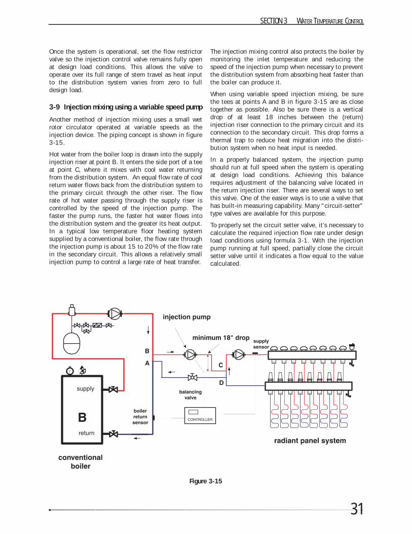
Another method of injection mixing uses a small wetrotor circulator operated at variable speeds as theinjection device. The piping concept is shown in figure3-15.
Hot water from the boiler loop is drawn into the supplyinjection riser at point B. It enters the side port of a teeat point C, where it mixes with cool water returningfrom the distribution system. An equal flow rate of coolreturn water flows back from the distribution system tothe primary circuit through the other riser. The flowrate of hot water passing through the supply riser iscontrolled by the speed of the injection pump. Thefaster the pump runs, the faster hot water flows intothe distribution system and the greater its heat output.In a typical low temperature floor heating systemsupplied by a conventional boiler, the flow rate throughthe injection pump is about 15 to 20% of the flow ratein the secondary circuit. This allows a relatively smallinjection pump to control a large rate of heat transfer.
The injection mixing control also protects the boiler bymonitoring the inlet temperature and reducing thespeed of the injection pump when necessary to preventthe distribution system from absorbing heat faster thanthe boiler can produce it.
When using variable speed injection mixing, be surethe tees at points A and B in figure 3-15 are as closetogether as possible. Also be sure there is a verticaldrop of at least 18 inches between the (return)injection riser connection to the primary circuit and itsconnection to the secondary circuit. This drop forms athermal trap to reduce heat migration into the distri-bution system when no heat input is needed.
In a properly balanced system, the injection pumpshould run at full speed when the system is operatingat design load conditions. Achieving this balancerequires adjustment of the balancing valve located inthe return injection riser. There are several ways to setthis valve. One of the easier ways is to use a valve thathas built-in measuring capability. Many “circuit-setter”type valves are available for this purpose.
To properly set the circuit setter valve, it’s necessary tocalculate the required injection flow rate under designload conditions using formula 3-1. With the injectionpump running at full speed, partially close the circuitsetter valve until it indicates a flow equal to the valuecalculated.
SECTION 3 WATER TEMPERATURE CONTROL
Figure 3-15

SECTION
4
RADIANT FLOOR HEATING METHODS
The availability of modern materials such as Kitec pipe has allowed the market for hydronic radiant floor heatingto increase approximately ten fold over the last decade. Installation methods have been developed for manytypes of floor constructions in residential, commercial and industrial buildings. Each year these installationtechniques allow thousands of buildings to be equipped with what many consider to be the ultimate comfortheating system.
4-1 What is radiant heating?
Before discussing the installation details of radiant floor heating, it’s important to have a clear understanding ofhow radiant heating works as well as how it differs from other forms of heating.
Nature has three means of transferring heat from objects at a given temperature to objects at lower temperatures.
Conduction is how heat moves through solid materials, or from one solid material to another when the two are incontact. If you stand barefooted on a cool basement floor slab, heat transfers from your feet to the floor byconduction.
Convection is how heat moves between a solid surface and a fluid. The fluid may be either a liquid or a gas. Hotwater flowing through a pipe transfers heat to the inside wall of the pipe by convection. Likewise, air flowingacross the heat exchanger inside a furnace absorbs heat from the hot metal surfaces.
Radiant heat transfer occurs when infrared light leaves the surface of an object and travels to the surface(s) ofother cooler objects. Unlike conduction and convection, radiant heat transfer does not require a fluid or solidmaterial between the two objects transferring heating. It only requires a space between the two objects. Solarenergy travels approximately 93 million miles from the sun to the earth, through the emptiness of space, solelyas radiant energy. The radiant energy only becomes sensible heat when absorbed by a surface.
33
THE IPEX MANUAL OF MODERN HYDRONICS
34
The radiant energy emitted by the relatively lowtemperature heat emitters used in hydronic heating istechnically described as infrared electromagneticradiation. It’s simply light that the human eye can’tsee. However, other than the fact that it’s invisible,infrared light behaves just like visible light. It travels instraight lines at the speed of light (186,000 miles persecond), and can be partially reflected by polishedmetallic surfaces. Unlike warm air, radiant energytravels equally well in any direction. Up, down orsideways, direction simply doesn’t matter. This charac-teristic allows a heated ceiling to deliver radiant heatto the room below.
The radiant energy emitted by a warm floor, wall orceiling is a completely natural phenomenon that’sliterally as old as the universe itself. A surface warmedby sunlight gives off infrared radiation just like onewarmed by embedded tubing. The latter simply uses adifferent heat source and transport system to deliverheat to the surface. Most low temperature radiantpanels emit less than 1/10 the radiant flux of brightsunlight, and all of it is infrared as opposed to ultra-violet light. Even the human body gives off infraredradiation to cooler surrounding surfaces.
4-2 The Benefits of Hydronic Radiant FloorHeating
Radiant floor heating is considered by many as theultimate form of comfort heating. In addition to theadvantages of hydronic heating in general, warm floorsprovide benefits that virtually no other system canmatch. Any one of these benefits can become the “hotbutton” that convinces a discriminating customer toinstall a hydronic radiant floor heating system. Here’s asummary of these key benefits.
Unsurpassed thermal comfort:
Buildings equipped with radiant flooring have interiorenvironments that are highly favorable to humanthermal comfort. Unlike many systems that directlyheat the air, radiant floor heating gently warms thesurfaces of objects in the room as well as the air itself.The warm surfaces significantly reduce the rate of heatloss from the occupants, allowing most to feelcomfortable at room temperatures 3 to 5 deg. F. lowerthan with other methods of heating.
The air temperature at floor level is slightly higher thanthe average room temperature. This significantlyreduces the rate of heat loss from the feet and legs.Several feet above the floor, the air temperature beginsto decrease. Most people tend to feel more alert withslightly lower air temperatures at head level. The lowestair temperatures in the room typically occur just belowthe ceiling. The result is reduced heat loss through the
ceiling insulation and hence lower heating costs.
A system that’s out of sight:
Most people realize that just about every occupiedbuilding in North America needs a heating system.However, few enjoy looking at the heat emitters that area necessary part of that system. The fact that such heatemitters often restrict furniture placement further addsto their invasiveness.
With hydronic radiant floor heating, the floor surface isthe heat emitter. There’s no need to compromise theaesthetics of the space or restrict furniture placement.It’s a system that gives your clients a building interiorthat’s as thermally luxurious as it is aestheticallyelegant.
A quiet system:
One of the strengths of hydronic heating is its ability todeliver heat without delivering noise. A properlydesigned radiant floor heating system is the epitome ofsilence. The gas or oil burner on the boiler is often theonly component that makes any detectable noise, andit’s usually located in the mechanical room away fromthe occupied spaces.
A clean system:
One of the biggest complaints associated with forcedair heating is its tendency to distribute dust, odors andgerms throughout a house. In contrast to whole houseair movement, hydronic flooring heating creates verygentle (imperceptible) room air circulation. Manypeople who suffer from allergies have found thatradiant floor heating doesn’t aggravate the symptomsthe way a forced air system often does.
A durable system:
A slab type floor heating system is nearly as indestruc-tible as the slab itself. It’s the ideal way to heat garagefacilities, industrial buildings, recreation rooms orother buildings with high interior traffic.
A system that reduces fuel usage:
Hydronic floor heating systems have a proven record ofreduced energy usage relative to other forms ofheating, both in residential and commercial / industrialbuildings. The savings result from several factors suchas the ability to sustain comfort at lower indoor airtemperatures, reduced air temperature stratification,non-pressurization of rooms (which leads to higherrates of air leakage), and the ability to operate withlower water temperatures.
Savings vary from one building to the next. Althoughsome projects have shown savings in excess of 50%, amore conservative estimate is 10 to 20% in savings.
As energy costs continue to escalate, the ability to
35
reduce fuel consumption will play an increasinglyimportant role in how heating systems are selected.Hydronic radiant floor heating can keep energy costs toa minimum while also delivering exceptional comfort.It’s truly the benchmark system against which all othermethods of heating will be compared.
4-3 The History of Hydronic Radiant Floor Heating
The origins of hydronic radiant floor heating date backto the early 1900s when systems were installed usingwrought iron and steel piping. During the 1940s and50’s, many radiant floor heating systems were installedby embedding copper tubing in concrete slabs.Although the installations were somewhat crude incomparison to today, these early systems quicklyproved they could deliver unsurpassed comfort.
Some of these early systems are still in operation.However, others have long since been abandoned dueto fatigue or corrosion of the embedded metal tubing.Although the comfort they delivered was exceptional,too many of the early systems using embedded copper,steel or iron pipe eventually developed leaks. Consumerconfidence in the thought that a hydronic floor heatingsystem could provide both comfort as well as a long,trouble-free service life steadily declined. The debut ofcentral air conditioning in the late 50’s, along withstrong promotion of forced air (ducted) systems as a“preferred” means of delivering both heating andcooling all but eliminated the use of hydronic floorheating. Or so it seemed.
Ironically, as the hydronic floor heating market wasnearing extinction in North America, a new tubingmaterial was being developed in Western Europe. That
material was cross-linked polyethylene (or PEX). Itwould soon prove to be the single biggest factor under-lying the reemergence of hydronic floor heating inNorth America.
Europeans had amassed considerable experience withPEX and PEX-AL-PEX tubing in floor heating applica-tions by the time these products made their firstappearances on the North American market in the early1980’s. Slowly but surely these modern pipingmaterials demonstrated they could deliver comfort,easy installation and long life. The rest—as they say—is history.
Today consumers are learning about new methods forinstallation of hydronic floor heating as never before.They are seeking qualified professional installers andquality products. Kitec pipe and WarmRite accessorieslet you give these discriminating consumers exactlywhat they’re looking for. Read on to see all the differentways these systems can be installed.
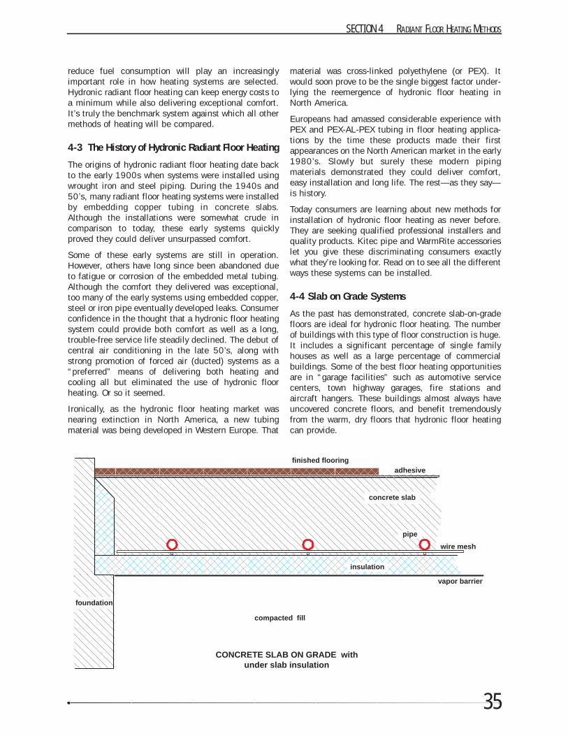
4-4 Slab on Grade Systems
As the past has demonstrated, concrete slab-on-gradefloors are ideal for hydronic floor heating. The numberof buildings with this type of floor construction is huge.It includes a significant percentage of single familyhouses as well as a large percentage of commercialbuildings. Some of the best floor heating opportunitiesare in “garage facilities” such as automotive servicecenters, town highway garages, fire stations andaircraft hangers. These buildings almost always haveuncovered concrete floors, and benefit tremendouslyfrom the warm, dry floors that hydronic floor heatingcan provide.
SECTION 4 RADIANT FLOOR HEATING METHODS
concrete slab
pipe
wire mesh
insulation
foundation
adhesivefinished flooring
vapor barrier
compacted fill
CONCRETE SLAB ON GRADE withunder slab insulation
THE IPEX MANUAL OF MODERN HYDRONICS
36
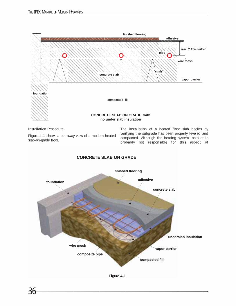
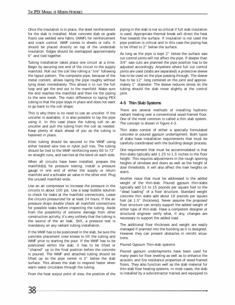
Installation Procedure:
Figure 4-1 shows a cut-away view of a modern heatedslab-on-grade floor.
The installation of a heated floor slab begins byverifying the subgrade has been properly leveled andcompacted. Although the heating system installer isprobably not responsible for this aspect of
Figure 4-1
concrete slab
pipe
wire mesh
foundation
adhesivefinished flooring
vapor barrier
compacted fill
CONCRETE SLAB ON GRADE withno under slab insulation
"chair"
max. 2" from surface
37
construction, failing to check for proper subgradepreparation could eventually compromise theembedded tubing circuits. It could also leave theinstaller having to defend why the floor heating systemisn’t at least partly responsible for cracks in the slab orother defects.
After the subgrade has been prepared, the soil vaporbarrier and underslab insulation should be installed.Some building specifications may not call for anunderslab vapor barrier. However, its ability to resistmoisture migration from the underlying soils can beindispensable, especially when wood products are usedas the finish flooring.
Heat loss from the edge and underside of a heated slabon grade can be substantial, especially in areas withhigh water tables or where the slab rests on bedrock.Edge and underslab insulation are essential inreducing these losses. They are a necessary part of anyquality floor heating system. Not taking steps tomitigate such heat loss is like leaving the windowsopen throughout the winter.
Realistically there’s only one opportunity to installunderslab insulation—before the slab is poured.Discovering high downward heat loss after the systemis in operation is a situation that’s virtually impossibleto correct. It makes little sense to attempt the instal-lation of a high quality heating system while omittingcrucial and relatively low cost details. Do it right thefirst time.
The most commonly used material for slab edge andunderside insulation is extruded polystyrene. It’s soldin 2 by 8 foot and 4 by 8 foot sheets in several thick-nesses. It’s also available in several densities to handledifferent floor loading. Extruded polystyrene panels arehighly resistant to moisture absorption, and have awell-established record in ground contact insulationapplications.
New insulating materials are developed to promote theuse of under slab insulation. One of them is calledradiant barrier foil. It is a composite of plastic andaluminum layers. The concrete Barrier Foils consists ofan aluminum layer sandwiched between two layers of“bubble” insulation. The “insulating” effect of thisnew product is comparable with the rigid foamproducts, but its handling and resistance tomechanical damage is far superior.
The amount of underside insulation depends on severalfactors. Among them are:
• The severity of the climate: colder climates justify edge- and underside insulation of greater R-value.
• The cost of energy: higher energy costs justify
edge- and underside insulation of greater R-value.
• The thermal resistance (R-value) of the floor covering(s): high thermal resistance coveringsjustify edge- and underside insulation of greater R-value.
• The shape of the slab: slabs with high ratios ofedge length to floor area justify edge- and underside insulation of greater R-value.
In most buildings the underslab insulation should havea minimum R-value of 5. In colder climates, it is oftenrecommended that the outer 4 feet of the slab (referredto as the “outer band”) have R-10 undersideinsulation. The insulation is generally omitted understructural bearing points such as beneath interiorcolumns or bearing walls.
The edge of the slab is especially vulnerable to heatloss. It should be insulated to a minimum of R-5 inmild climates and R-10 in colder climates.
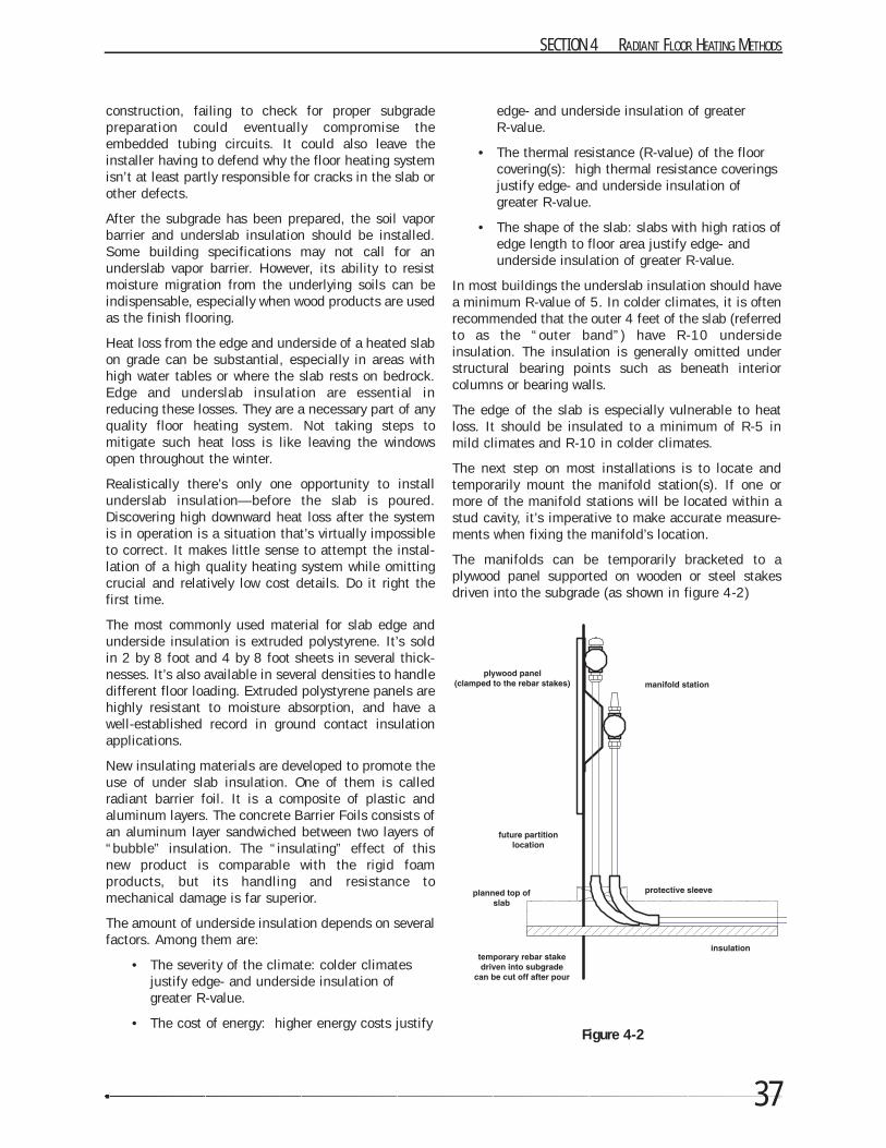
The next step on most installations is to locate andtemporarily mount the manifold station(s). If one ormore of the manifold stations will be located within astud cavity, it’s imperative to make accurate measure-ments when fixing the manifold’s location.
The manifolds can be temporarily bracketed to aplywood panel supported on wooden or steel stakesdriven into the subgrade (as shown in figure 4-2)
SECTION 4 RADIANT FLOOR HEATING METHODS
Figure 4-2
THE IPEX MANUAL OF MODERN HYDRONICS
38
Once the insulation is in place, the steel reinforcementfor the slab is installed. Most concrete slab on gradefloors use welded wire fabric (WWF) for reinforcementand crack control. WWF comes in sheets or rolls. Itshould be placed directly on top of the underslabinsulation. Edges should be overlapped approximately6” and tied together.
Tubing installation takes place one circuit at a time.Begin by securing one end of the circuit to the supplymanifold. Roll out the coil like rolling a “tire” followingthe layout pattern. The composite pipe, because of themetal content, allows laying the pipe roughly withouttying down immediately. This allows it to run the fullloop and get the end out to the manifold. Make surethe end reaches the manifold and then tie the pipingto the wire mesh. The main difference to laying PEXtubing is that the pipe stays in place and does not wantto go back to the coil shape.
This is why there is no need to use an uncoiler. If theuncoiler is available, it is also possible to lay the pipeusing it. In this case place the tubing coil on anuncoiler and pull the tubing from the coil as needed.Keep plenty of slack ahead of you as the tubing isfastened in place.
Kitec tubing should be secured to the WWF usingeither twisted wire ties or nylon pull ties. The tubingshould be tied to the WWF reinforcing every 60 to 72”on straight runs, and two ties at the bend on each side.
When all circuits have been installed, prepare themanifold(s) for pressure testing. Install a pressuregauge in one end of either the supply or returnmanifold and a schrader air valve in the other end. Plugthe unused manifold ends.
Use an air compressor to increase the pressure in thecircuits to about 100 psi. Use a soap bubble solutionto check for leaks at the manifold connections. Leavethe circuits pressurized for at least 24 hours. If the airpressure drops double check all manifold connectionsfor possible leaks before inspecting the tubing. Asidefrom the possibility of extreme damage from otherconstruction activity, it’s very unlikely that the tubing isthe source of the air leak. Still, a pressure test ismandatory on any radiant tubing installation.
If the WWF has to be positioned in the slab, be sure theconcrete placement crew knows to lift the tubing andWWF prior to starting the pour. If the WWF has to bepositioned within the slab, it has to be lifted or“chaired” up to the final position before the concreteis poured. The WWF and attached tubing should belifted up so the pipe center is 2” below the slabsurface. This allows the slab to respond faster whenwarm water circulates through the tubing.
From the heat output point of view, the position of the
piping in the slab is not so critical if full slab insulationis used. Appropriate thermal break will direct the heatflow towards the surface. If insulation is not used thepipe position is critical and in this case the piping hasto be lifted to 2” below the surface.
As long as the pipe is kept 2” below the surface sawcut control joints will not affect the pipe. If deeper than3/4” saw cuts are planned the pipe position has to beadjusted accordingly. Anywhere where full cut controljoints are used (slabs are separated) a protective sleevehas to be used on the pipe passing through. The sleevehas to be 12” long centered on the joint and approxi-mately 1” diameter. The sleeve reduces stress on thetubing should the slab move slightly at the controljoint.
4-5 Thin Slab Systems
There are several methods of installing hydronicradiant heating over a conventional wood-framed floor.One of the most common is called a thin slab system.The concept is shown in figure 4-3.
Thin slabs consist of either a specially formulatedconcrete or poured gypsum underlayment. Both typesof slabs have installation requirements that must becarefully coordinated with the building design process.
One requirement that must be accommodated is thatthin-slabs typically add 1.25 to 1.5 inches to the floorheight. This requires adjustments in the rough openingheights of windows and doors as well as the height ofdoor thresholds. It will also affect the riser heights onstairs.
Another issue that must be addressed is the addedweight of the thin-slab. Poured gypsum thin-slabstypically add 13 to 15 pounds per square foot to the“dead loading” of a floor structure. Standard weightconcrete thin slabs add about 18 pounds per squarefoot (at 1.5” thickness). Never assume the proposedfloor structure can simply support the added weight ofeither type of thin-slab. Have a competent designer orstructural engineer verify what, if any, changes arenecessary to support the added load.
The additional floor thickness and weight are easilymanaged if planned into the building as it is designed.However they can present obstacles in retrofit situa-tions.
Poured Gypsum Thin-slab systems
Poured gypsum underlayments have been used formany years for floor leveling as well as to enhance theacoustic and fire resistance properties of wood-framedfloors. They also function well as the slab material forthin-slab floor heating systems. In most cases, the slabis installed by a subcontractor trained and equipped to
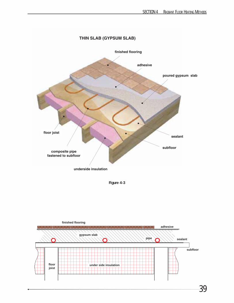
39
SECTION 4 RADIANT FLOOR HEATING METHODS
gypsum slabpipe
under side insulation
adhesivefinished flooring
sealant
floorjoist
subfloor
Figure 4-3
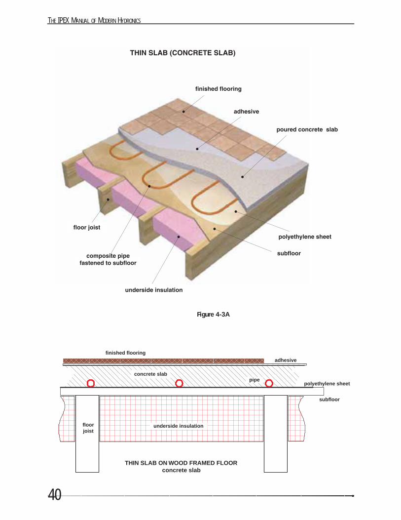
THE IPEX MANUAL OF MODERN HYDRONICS
40
concrete slabpipe
underside insulation
adhesivefinished flooring
polyethylene sheet
THIN SLAB ON WOOD FRAMED FLOORconcrete slab
floorjoist
subfloor
Figure 4-3A
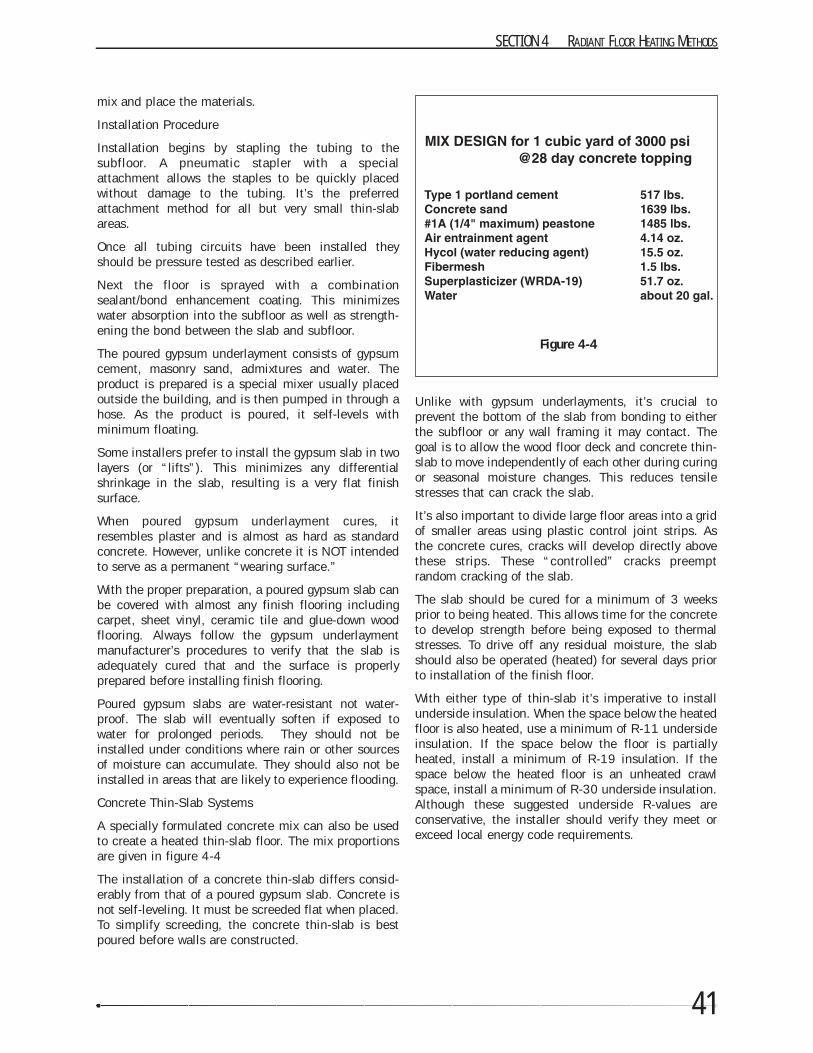
41
mix and place the materials.
Installation Procedure
Installation begins by stapling the tubing to thesubfloor. A pneumatic stapler with a specialattachment allows the staples to be quickly placedwithout damage to the tubing. It’s the preferredattachment method for all but very small thin-slabareas.
Once all tubing circuits have been installed theyshould be pressure tested as described earlier.
Next the floor is sprayed with a combinationsealant/bond enhancement coating. This minimizeswater absorption into the subfloor as well as strength-ening the bond between the slab and subfloor.
The poured gypsum underlayment consists of gypsumcement, masonry sand, admixtures and water. Theproduct is prepared is a special mixer usually placedoutside the building, and is then pumped in through ahose. As the product is poured, it self-levels withminimum floating.
Some installers prefer to install the gypsum slab in twolayers (or “lifts”). This minimizes any differentialshrinkage in the slab, resulting is a very flat finishsurface.
When poured gypsum underlayment cures, itresembles plaster and is almost as hard as standardconcrete. However, unlike concrete it is NOT intendedto serve as a permanent “wearing surface.”
With the proper preparation, a poured gypsum slab canbe covered with almost any finish flooring includingcarpet, sheet vinyl, ceramic tile and glue-down woodflooring. Always follow the gypsum underlaymentmanufacturer’s procedures to verify that the slab isadequately cured that and the surface is properlyprepared before installing finish flooring.
Poured gypsum slabs are water-resistant not water-proof. The slab will eventually soften if exposed towater for prolonged periods. They should not beinstalled under conditions where rain or other sourcesof moisture can accumulate. They should also not beinstalled in areas that are likely to experience flooding.
Concrete Thin-Slab Systems
A specially formulated concrete mix can also be usedto create a heated thin-slab floor. The mix proportionsare given in figure 4-4
The installation of a concrete thin-slab differs consid-erably from that of a poured gypsum slab. Concrete isnot self-leveling. It must be screeded flat when placed.To simplify screeding, the concrete thin-slab is bestpoured before walls are constructed.
Unlike with gypsum underlayments, it’s crucial toprevent the bottom of the slab from bonding to eitherthe subfloor or any wall framing it may contact. Thegoal is to allow the wood floor deck and concrete thin-slab to move independently of each other during curingor seasonal moisture changes. This reduces tensilestresses that can crack the slab.
It’s also important to divide large floor areas into a gridof smaller areas using plastic control joint strips. Asthe concrete cures, cracks will develop directly abovethese strips. These “controlled” cracks preemptrandom cracking of the slab.
The slab should be cured for a minimum of 3 weeksprior to being heated. This allows time for the concreteto develop strength before being exposed to thermalstresses. To drive off any residual moisture, the slabshould also be operated (heated) for several days priorto installation of the finish floor.
With either type of thin-slab it’s imperative to installunderside insulation. When the space below the heatedfloor is also heated, use a minimum of R-11 undersideinsulation. If the space below the floor is partiallyheated, install a minimum of R-19 insulation. If thespace below the heated floor is an unheated crawlspace, install a minimum of R-30 underside insulation.Although these suggested underside R-values areconservative, the installer should verify they meet orexceed local energy code requirements.
SECTION 4 RADIANT FLOOR HEATING METHODS
Figure 4-4
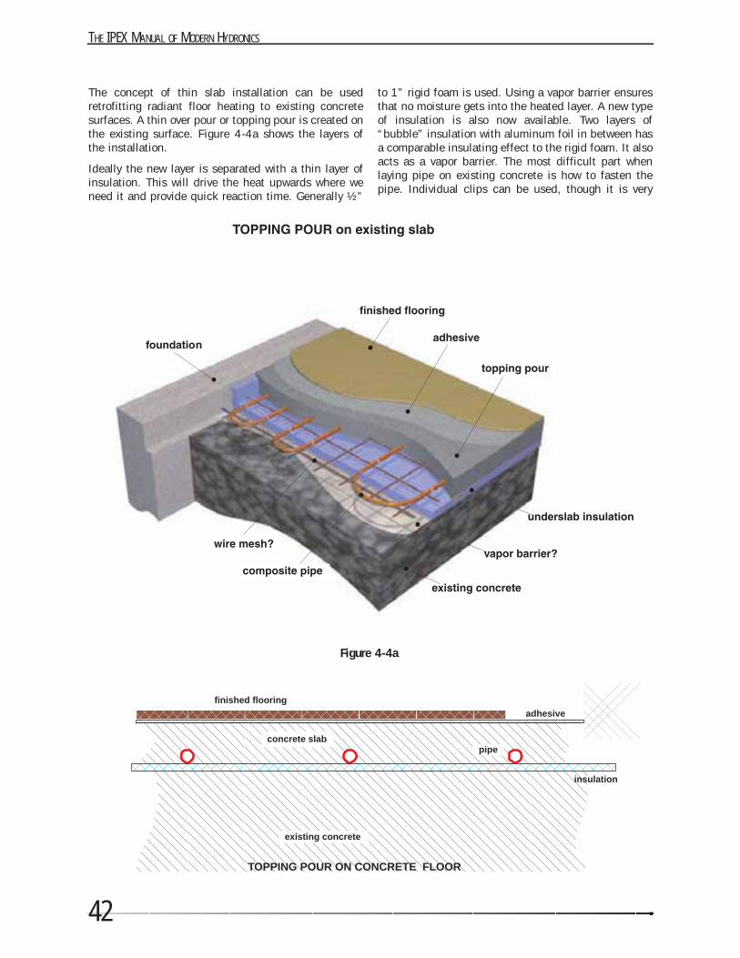
THE IPEX MANUAL OF MODERN HYDRONICS
42
The concept of thin slab installation can be usedretrofitting radiant floor heating to existing concretesurfaces. A thin over pour or topping pour is created onthe existing surface. Figure 4-4a shows the layers ofthe installation.
Ideally the new layer is separated with a thin layer ofinsulation. This will drive the heat upwards where weneed it and provide quick reaction time. Generally ½”
to 1” rigid foam is used. Using a vapor barrier ensuresthat no moisture gets into the heated layer. A new typeof insulation is also now available. Two layers of“bubble” insulation with aluminum foil in between hasa comparable insulating effect to the rigid foam. It alsoacts as a vapor barrier. The most difficult part whenlaying pipe on existing concrete is how to fasten thepipe. Individual clips can be used, though it is very
Figure 4-4a
concrete slabpipe
adhesivefinished flooring
existing concrete
TOPPING POUR ON CONCRETE FLOOR
insulation
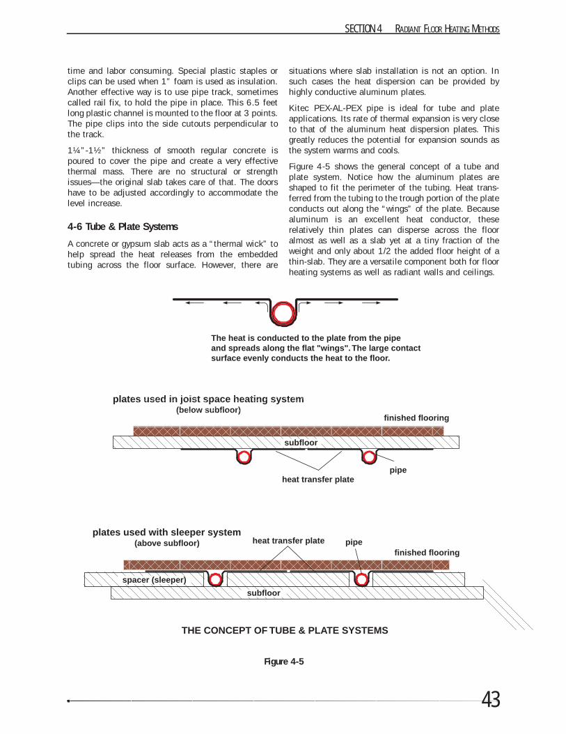
43
time and labor consuming. Special plastic staples orclips can be used when 1” foam is used as insulation.Another effective way is to use pipe track, sometimescalled rail fix, to hold the pipe in place. This 6.5 feetlong plastic channel is mounted to the floor at 3 points.The pipe clips into the side cutouts perpendicular tothe track.
1¼”-1½” thickness of smooth regular concrete ispoured to cover the pipe and create a very effectivethermal mass. There are no structural or strengthissues—the original slab takes care of that. The doorshave to be adjusted accordingly to accommodate thelevel increase.
4-6 Tube & Plate Systems
A concrete or gypsum slab acts as a “thermal wick” tohelp spread the heat releases from the embeddedtubing across the floor surface. However, there are
situations where slab installation is not an option. Insuch cases the heat dispersion can be provided byhighly conductive aluminum plates.
Kitec PEX-AL-PEX pipe is ideal for tube and plateapplications. Its rate of thermal expansion is very closeto that of the aluminum heat dispersion plates. Thisgreatly reduces the potential for expansion sounds asthe system warms and cools.
Figure 4-5 shows the general concept of a tube andplate system. Notice how the aluminum plates areshaped to fit the perimeter of the tubing. Heat trans-ferred from the tubing to the trough portion of the plateconducts out along the “wings” of the plate. Becausealuminum is an excellent heat conductor, theserelatively thin plates can disperse across the flooralmost as well as a slab yet at a tiny fraction of theweight and only about 1/2 the added floor height of athin-slab. They are a versatile component both for floorheating systems as well as radiant walls and ceilings.
SECTION 4 RADIANT FLOOR HEATING METHODS
pipe
plates used in joist space heating system(below subfloor)
finished flooring
heat transfer plate
THE CONCEPT OF TUBE & PLATE SYSTEMS
subfloor
pipeplates used with sleeper system
(above subfloor)finished flooring
heat transfer plate
subfloor
spacer (sleeper)
The heat is conducted to the plate from the pipeand spreads along the flat "wings". The large contactsurface evenly conducts the heat to the floor.
Figure 4-5
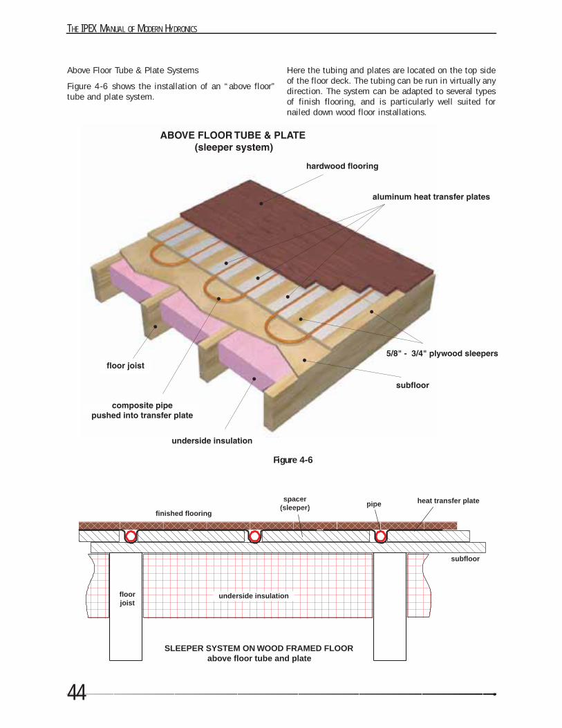
THE IPEX MANUAL OF MODERN HYDRONICS
44
Above Floor Tube & Plate Systems
Figure 4-6 shows the installation of an “above floor”tube and plate system.
Here the tubing and plates are located on the top sideof the floor deck. The tubing can be run in virtually anydirection. The system can be adapted to several typesof finish flooring, and is particularly well suited fornailed down wood floor installations.
Figure 4-6
spacer(sleeper) pipe
underside insulation
finished flooring
SLEEPER SYSTEM ON WOOD FRAMED FLOORabove floor tube and plate
floorjoist
subfloor
heat transfer plate
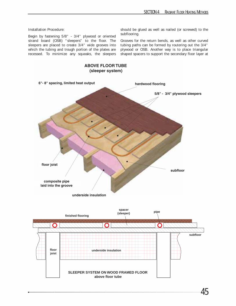
45
Installation Procedure:
Begin by fastening 5/8” - 3/4” plywood or orientedstrand board (OSB) “sleepers” to the floor. Thesleepers are placed to create 3/4” wide grooves intowhich the tubing and trough portion of the plates arerecessed. To minimize any squeaks, the sleepers
should be glued as well as nailed (or screwed) to thesubflooring.
Grooves for the return bends, as well as other curvedtubing paths can be formed by routering out the 3/4”plywood or OSB. Another way is to place triangularshaped spacers to support the secondary floor layer at
SECTION 4 RADIANT FLOOR HEATING METHODS
spacer(sleeper) pipe
underside insulation
finished flooring
SLEEPER SYSTEM ON WOOD FRAMED FLOORabove floor tube
floorjoist
subfloor
THE IPEX MANUAL OF MODERN HYDRONICS
46
curved areas.
The plates are set into the grooves with ends spacedabout 1” apart. Pull each plate against one edge of thesleeper and tack it in place with two or three lightgauge staples on the same side (and only on this side).This allows the plate to expand as the tubing is pushedinto it as well as when the plate heats and cools.
Then tubing is laid out and pushed into the grooves inthe plates. Stepping on the tube as it aligns with thegrooves ensures it is pushed all the way into the groove.
It is NOT necessary to install silicone caulking into thetroughs of the plates when installing Kitec PEX-AL-PEXpipe.
Above floor tube and plate systems are ideal whennailed-down wood flooring will be installed. Theflooring can be placed directly over the tube and plateswithout needing an additional cover sheet. The flooringshould be installed with its long dimension perpen-dicular to the tubing. Nails can be driven through theheat transfer plates, through the sleepers and into thesubfloor. Be careful not to drive nails through thetubing on return bends or other areas when the tubingis not visible as the flooring is laid. If the tubing needsto run parallel to the flooring at times, it is best to drilla shallow hole through the subfloor and route thetubing through the floor framing where it is protectedagainst nail punctures. The tubing can also be“plunged” beneath the subfloor and then routed upthrough the bottom plate of a partition to connect tothe manifolds.
For other types of flooring, it is necessary to install athin 1/4” or 3/8” cover sheet over the tube and platesto serve as a smooth stable substrate. Plywood is oftenused as the cover sheet under vinyl flooring or carpet.Cement board has also been used under ceramic tile.All tubing circuits should be pressure tested prior toinstalling the cover sheet. The tubing should remainpressurized as the cover sheet is installed. Be carefulnot to drive fasteners through the tubing when securingthe cover sheet.
The same concept of the sleeper system can be usedin low heat load installations, but without the heattransfer plates—mostly for floor warming systems.
The wood structure is a poor conductor of heat so thereis limited heat transfer sideways. The relatively thinlayer directly above the pipe will allow a lot more heatthrough than sideways. This results in large localtemperature differences depending on the position ofthe pipe. This effect limits the amount of heat that canbe transferred without creating high temperature“lines” on the floor surface.
The spacing used should be 6”-8” and again only a
limited amount of heat output can be provided. Toovercome this limitation, some manufacturers producepre-routed plywood sheets with aluminum layerattached to it to improve sideways transfer.
Below floor tube & plate systems
It’s also possible to fasten the tubing and aluminumheat dispersion plates against the bottom of thesubfloor. Below floor tube and plate systems work wellwhen raising the floor level is not an option. Theconcept is shown in figure 4-7.
The plate cradles the tubing against the subfloor aswell as disperses the heat across the floor to avoidobjectionable variations in floor surface temperatures.
The ideal installation conditions for this system wouldbe completely unobstructed floor joist cavities.However this is often not what the installer has to dealwith. In some cases, plumbing, electrical, ducting orother utilities may already be routed through the joistcavities. This could make access to the underside ofthe subfloor difficult or even impossible. Alwaysinspect the underside of the floor deck beforecommitting to a below floor tube & plate installationmethod.
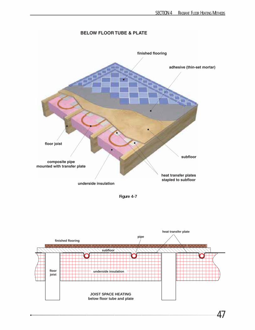
47
SECTION 4 RADIANT FLOOR HEATING METHODS
Figure 4-7
pipe
underside insulation
finished flooring
heat transfer plate
JOIST SPACE HEATINGbelow floor tube and plate
floorjoist
subfloor
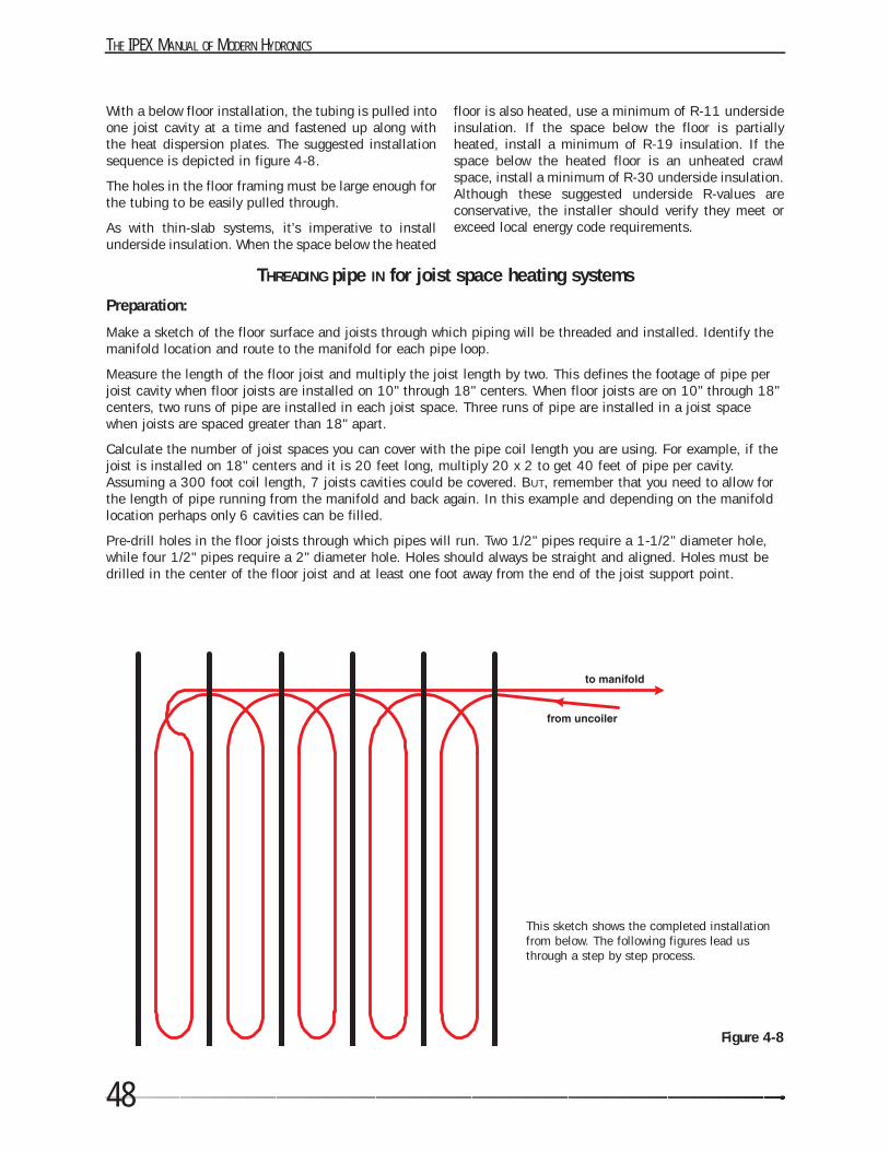
THE IPEX MANUAL OF MODERN HYDRONICS
48
With a below floor installation, the tubing is pulled intoone joist cavity at a time and fastened up along withthe heat dispersion plates. The suggested installationsequence is depicted in figure 4-8.
The holes in the floor framing must be large enough forthe tubing to be easily pulled through.
As with thin-slab systems, it’s imperative to installunderside insulation. When the space below the heated
floor is also heated, use a minimum of R-11 undersideinsulation. If the space below the floor is partiallyheated, install a minimum of R-19 insulation. If thespace below the heated floor is an unheated crawlspace, install a minimum of R-30 underside insulation.Although these suggested underside R-values areconservative, the installer should verify they meet orexceed local energy code requirements.
Figure 4-8
THREADING pipe IN for joist space heating systems
Preparation:
Make a sketch of the floor surface and joists through which piping will be threaded and installed. Identify themanifold location and route to the manifold for each pipe loop.
Measure the length of the floor joist and multiply the joist length by two. This defines the footage of pipe perjoist cavity when floor joists are installed on 10" through 18" centers. When floor joists are on 10" through 18"centers, two runs of pipe are installed in each joist space. Three runs of pipe are installed in a joist spacewhen joists are spaced greater than 18" apart.
Calculate the number of joist spaces you can cover with the pipe coil length you are using. For example, if thejoist is installed on 18" centers and it is 20 feet long, multiply 20 x 2 to get 40 feet of pipe per cavity.Assuming a 300 foot coil length, 7 joists cavities could be covered. BUT, remember that you need to allow forthe length of pipe running from the manifold and back again. In this example and depending on the manifoldlocation perhaps only 6 cavities can be filled.
Pre-drill holes in the floor joists through which pipes will run. Two 1/2" pipes require a 1-1/2" diameter hole,while four 1/2" pipes require a 2" diameter hole. Holes should always be straight and aligned. Holes must bedrilled in the center of the floor joist and at least one foot away from the end of the joist support point.
This sketch shows the completed installationfrom below. The following figures lead usthrough a step by step process.
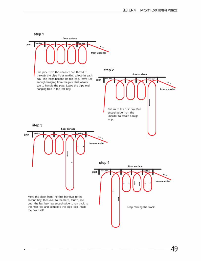
49
SECTION 4 RADIANT FLOOR HEATING METHODS
Pull pipe from the uncoiler and thread itthrough the pipe holes making a loop in eachbay. The loops needn’t be too long, leave justenough hanging from the joist that allowsyou to handle the pipe. Leave the pipe endhanging free in the last bay.
Move the slack from the first bay over to thesecond bay, then over to the third, fourth, etc.,until the last bay has enough pipe to run back tothe manifold and complete the pipe loop insidethe bay itself.
Keep moving the slack!
Return to the first bay. Pullenough pipe from theuncoiler to create a largeloop.
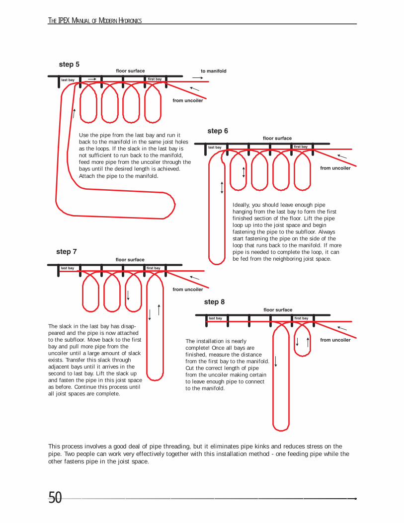
THE IPEX MANUAL OF MODERN HYDRONICS
50
Use the pipe from the last bay and run itback to the manifold in the same joist holesas the loops. If the slack in the last bay isnot sufficient to run back to the manifold,feed more pipe from the uncoiler through thebays until the desired length is achieved.Attach the pipe to the manifold.
Ideally, you should leave enough pipehanging from the last bay to form the firstfinished section of the floor. Lift the pipeloop up into the joist space and beginfastening the pipe to the subfloor. Alwaysstart fastening the pipe on the side of theloop that runs back to the manifold. If morepipe is needed to complete the loop, it canbe fed from the neighboring joist space.
The slack in the last bay has disap-peared and the pipe is now attachedto the subfloor. Move back to the firstbay and pull more pipe from theuncoiler until a large amount of slackexists. Transfer this slack throughadjacent bays until it arrives in thesecond to last bay. Lift the slack upand fasten the pipe in this joist spaceas before. Continue this process untilall joist spaces are complete.
This process involves a good deal of pipe threading, but it eliminates pipe kinks and reduces stress on thepipe. Two people can work very effectively together with this installation method - one feeding pipe while theother fastens pipe in the joist space.
The installation is nearlycomplete! Once all bays arefinished, measure the distancefrom the first bay to the manifold.Cut the correct length of pipefrom the uncoiler making certainto leave enough pipe to connectto the manifold.
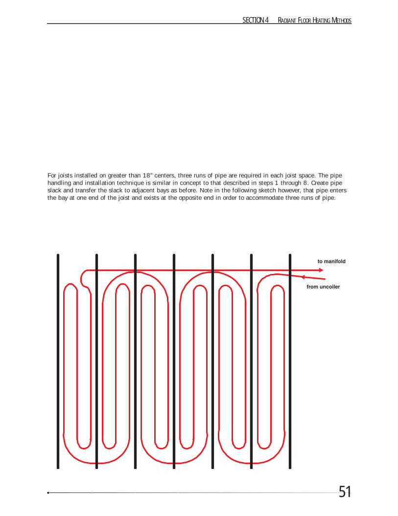
51
SECTION 4 RADIANT FLOOR HEATING METHODS
For joists installed on greater than 18" centers, three runs of pipe are required in each joist space. The pipehandling and installation technique is similar in concept to that described in steps 1 through 8. Create pipeslack and transfer the slack to adjacent bays as before. Note in the following sketch however, that pipe entersthe bay at one end of the joist and exists at the opposite end in order to accommodate three runs of pipe.
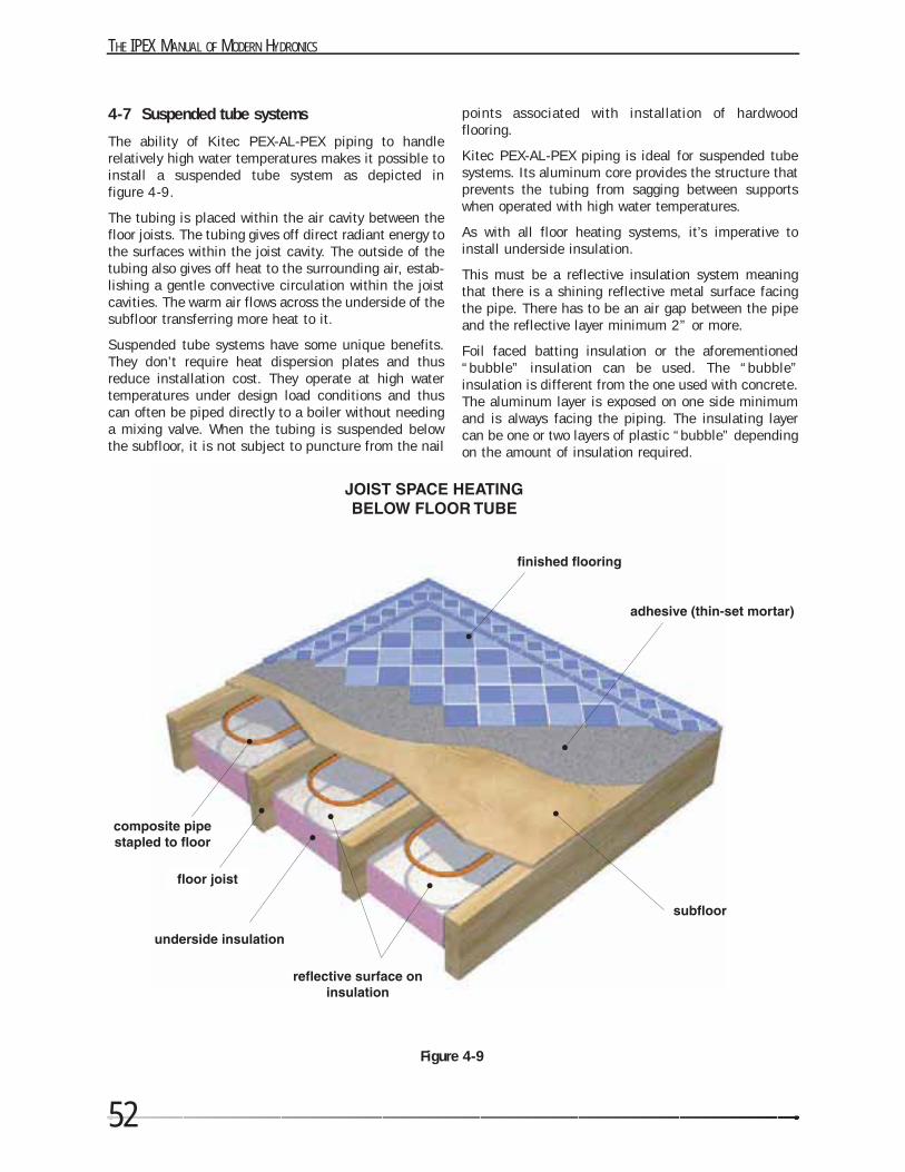
THE IPEX MANUAL OF MODERN HYDRONICS
52
4-7 Suspended tube systems
The ability of Kitec PEX-AL-PEX piping to handlerelatively high water temperatures makes it possible toinstall a suspended tube system as depicted in figure 4-9.
The tubing is placed within the air cavity between thefloor joists. The tubing gives off direct radiant energy tothe surfaces within the joist cavity. The outside of thetubing also gives off heat to the surrounding air, estab-lishing a gentle convective circulation within the joistcavities. The warm air flows across the underside of thesubfloor transferring more heat to it.
Suspended tube systems have some unique benefits.They don’t require heat dispersion plates and thusreduce installation cost. They operate at high watertemperatures under design load conditions and thuscan often be piped directly to a boiler without needinga mixing valve. When the tubing is suspended belowthe subfloor, it is not subject to puncture from the nail
points associated with installation of hardwoodflooring.
Kitec PEX-AL-PEX piping is ideal for suspended tubesystems. Its aluminum core provides the structure thatprevents the tubing from sagging between supportswhen operated with high water temperatures.
As with all floor heating systems, it’s imperative toinstall underside insulation.
This must be a reflective insulation system meaningthat there is a shining reflective metal surface facingthe pipe. There has to be an air gap between the pipeand the reflective layer minimum 2” or more.
Foil faced batting insulation or the aforementioned“bubble” insulation can be used. The “bubble”insulation is different from the one used with concrete.The aluminum layer is exposed on one side minimumand is always facing the piping. The insulating layercan be one or two layers of plastic “bubble” dependingon the amount of insulation required.
Figure 4-9
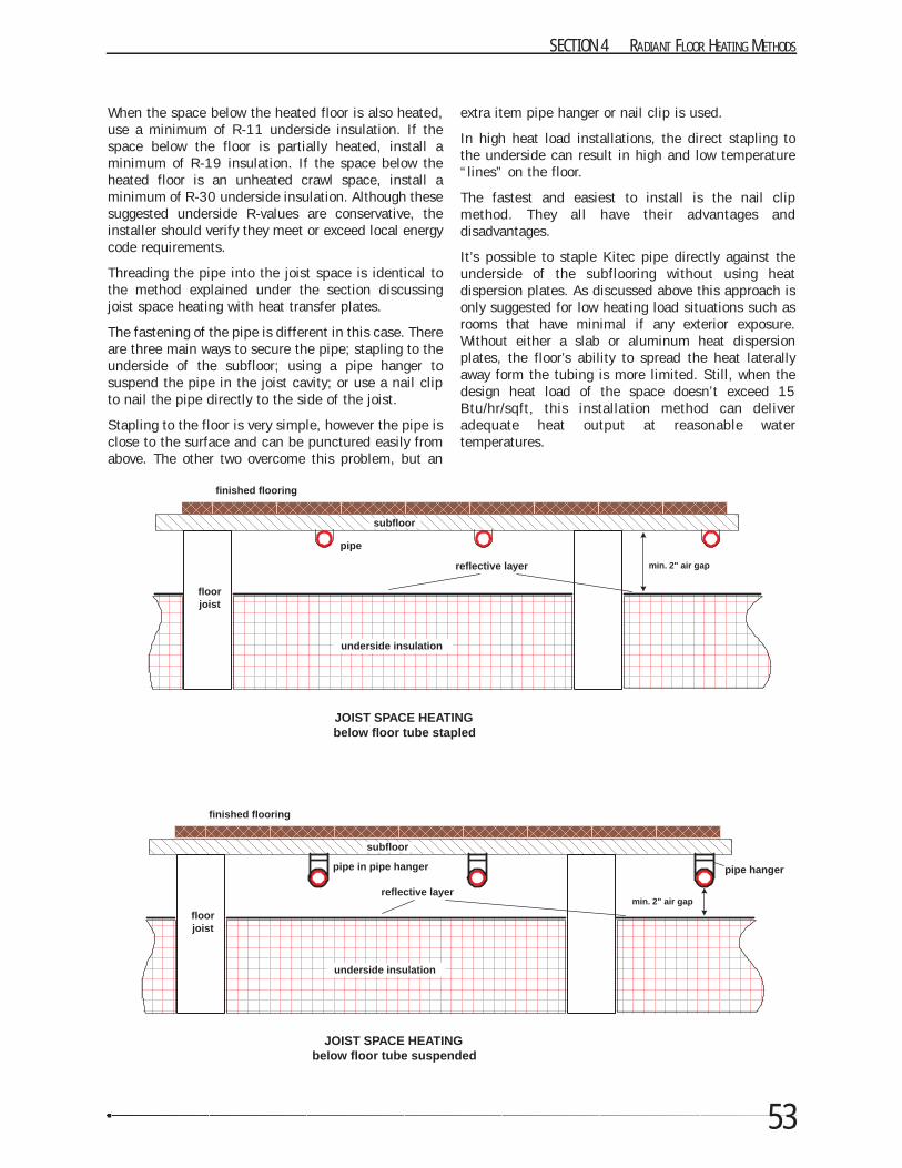
53
SECTION 4 RADIANT FLOOR HEATING METHODS
When the space below the heated floor is also heated,use a minimum of R-11 underside insulation. If thespace below the floor is partially heated, install aminimum of R-19 insulation. If the space below theheated floor is an unheated crawl space, install aminimum of R-30 underside insulation. Although thesesuggested underside R-values are conservative, theinstaller should verify they meet or exceed local energycode requirements.
Threading the pipe into the joist space is identical tothe method explained under the section discussingjoist space heating with heat transfer plates.
The fastening of the pipe is different in this case. Thereare three main ways to secure the pipe; stapling to theunderside of the subfloor; using a pipe hanger tosuspend the pipe in the joist cavity; or use a nail clipto nail the pipe directly to the side of the joist.
Stapling to the floor is very simple, however the pipe isclose to the surface and can be punctured easily fromabove. The other two overcome this problem, but an
extra item pipe hanger or nail clip is used.
In high heat load installations, the direct stapling tothe underside can result in high and low temperature“lines” on the floor.
The fastest and easiest to install is the nail clipmethod. They all have their advantages and disadvantages.
It’s possible to staple Kitec pipe directly against theunderside of the subflooring without using heatdispersion plates. As discussed above this approach isonly suggested for low heating load situations such asrooms that have minimal if any exterior exposure.Without either a slab or aluminum heat dispersionplates, the floor’s ability to spread the heat laterallyaway form the tubing is more limited. Still, when thedesign heat load of the space doesn’t exceed 15Btu/hr/sqft, this installation method can deliveradequate heat output at reasonable water temperatures.
pipe
underside insulation
finished flooring
JOIST SPACE HEATINGbelow floor tube stapled
floorjoist
subfloor
reflective layer min. 2" air gap
pipe in pipe hanger
underside insulation
finished flooring
JOIST SPACE HEATINGbelow floor tube suspended
floorjoist
subfloor
reflective layermin. 2" air gap
pipe hanger
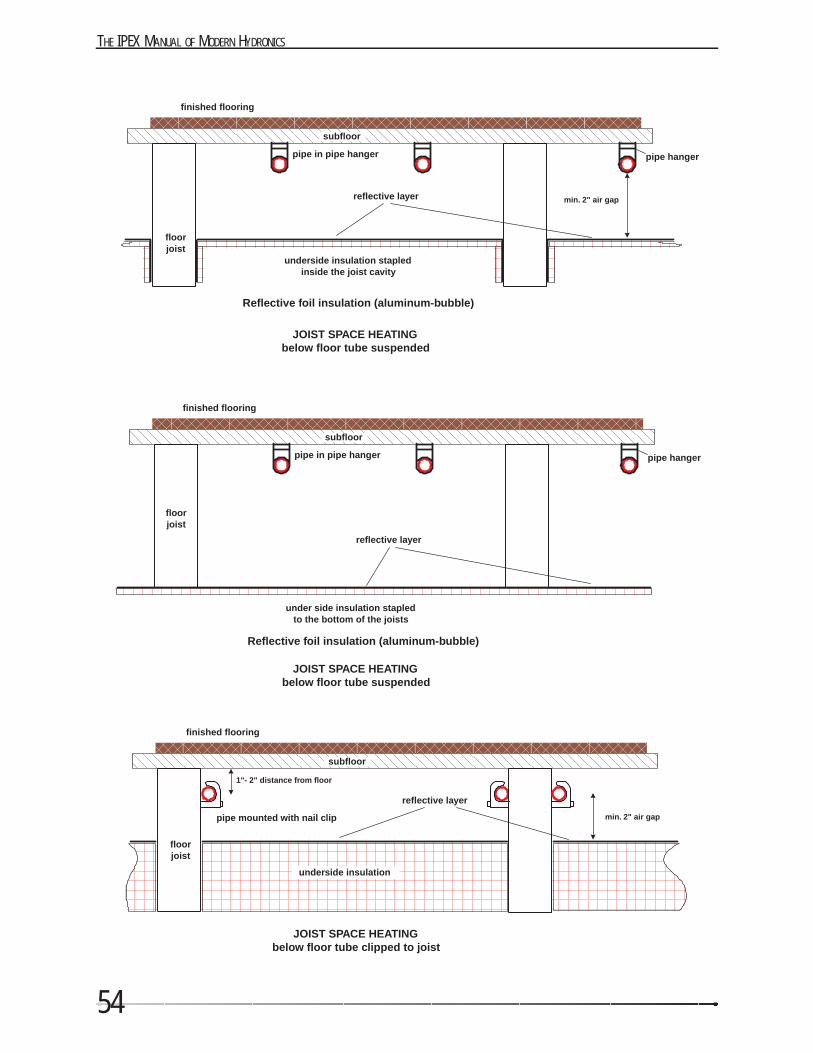
THE IPEX MANUAL OF MODERN HYDRONICS
54
pipe in pipe hanger
underside insulation stapledinside the joist cavity
finished flooring
JOIST SPACE HEATINGbelow floor tube suspended
floorjoist
subfloor
reflective layer min. 2" air gap
pipe hanger
Reflective foil insulation (aluminum-bubble)
pipe in pipe hanger
under side insulation stapledto the bottom of the joists
finished flooring
JOIST SPACE HEATINGbelow floor tube suspended
floorjoist
subfloor
reflective layer
pipe hanger
Reflective foil insulation (aluminum-bubble)
pipe mounted with nail clip
underside insulation
finished flooring
JOIST SPACE HEATINGbelow floor tube clipped to joist
floorjoist
subfloor
reflective layer
min. 2" air gap
1"- 2" distance from floor
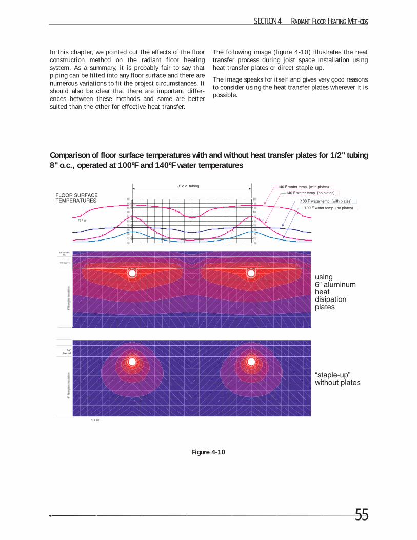
55
SECTION 4 RADIANT FLOOR HEATING METHODS
In this chapter, we pointed out the effects of the floorconstruction method on the radiant floor heatingsystem. As a summary, it is probably fair to say thatpiping can be fitted into any floor surface and there arenumerous variations to fit the project circumstances. Itshould also be clear that there are important differ-ences between these methods and some are bettersuited than the other for effective heat transfer.
The following image (figure 4-10) illustrates the heattransfer process during joist space installation usingheat transfer plates or direct staple up.
The image speaks for itself and gives very good reasonsto consider using the heat transfer plates wherever it ispossible.
Figure 4-10
Comparison of floor surface temperatures with and without heat transfer plates for 1/2" tubing8" o.c., operated at 100ºF and 140ºF water temperatures