manual of naval preventive medicine · manual of naval preventive medicine chapter 7 wastewater...
TRANSCRIPT
Bureau ofMedicine and Surgery NAVMED P010-7 (Rev. 1995)Washington, D.C. 20372-5300 0510-LP-209-9600
Manual of Naval Preventive Medicine
Chapter 7
WASTEWATER TREATMENTAND DISPOSAL,
ASHORE AND AFLOAT
DISTRIBUTION STATEMENT “A”
CONTENTS
Section I. GeneralArticle 7-1.
7-2.7-3.7-4.7-5.7-6.
Page
Scope . . . . . . . . . . . . . . . . . . . . . . . . . . . . . . . . . . . . . . . . . . . . . . . . . . . . . . . . . . . . . . . . . . . . . . . . . . . . . . . . . . . . . . . . . . . . . . . . . . . . . . . . . . . . . . 7-1Definitions . . . . . . . . . . . . . . . . . . . . . . . . . . . . . . . . . . . . . . . . . . . . . . . . . . . . . . . . . . . . . . . . . . . . . . . . . . . . . . . . . . . . . . . . . . . . . . . . . . . . . . 7-1National Effluent Guidelines . . . . . . . . . . . . . . . . . . . . . . . . . . . . . . . . . . . . . . . . . . . . . . . . . . . . . . . . . . . . . . . . . . . . . . . . . 7-2Policy . . . . . . . . . . . . . . . . . . . . . . . . . . . . . . . . . . . . . . . . . . . . . . . . . . . . . . . . . . . . . . . . . . . . . . . . . . . . . . . . . . . . . . . . . . . . . . . . . . . . . . . . . . . . . . 7-3Responsibilities . . . . . . . . . . . . . . . . . . . . . . . . . . . . . . . . . . . . . . . . . . . . . . . . . . . . . . . . . . . . . . . . . . . . . . . . . . . . . . . . . . . . . . . . . . . . . . 7-3Navy Discharge Permit Requirements . . . . . . . . . . . . . . . . . . . . . . . . . . . . . . . . . . . . . . . . . . . . . . . . . . . . . . . . . . 7-4
Section II. Wastewater Treatment and Disposal Systems Ashore
Section III.
Article 7-7.7-8.7-9.
7-10.7-11.7-12.7-13.7-14.7-15.
Introduction . . . . . . . . . . . . . . . . . . . . . . . . . . . . . . . . . . . . . . . . . . . . . . . . . . . . . . . . . . . . . . . . . . . . . . . . . . . . . . . . . . . . . . . . . . . . . . . . . . .Individual Sewage Disposal Systems . . . . . . . . . . . . . . . . . . . . . . . . . . . . . . . . . . . . . . . . . . . . . . . . . . . . . . . . . . . .Community Wastewater Treatment Systems . . . . . . . . . . . . . . . . . . . . . . . . . . . . . . . . . . . . . . . . . . . . . . .Disinfection . . . . . . . . . . . . . . . . . . . . . . . . . . . . . . . . . . . . . . . . . . . . . . . . . . . . . . . . . . . . . . . . . . . . . . . . . . . . . . . . . . . . . . . . . . . . . . . . . . . .Advanced Wastewater Treatment . . . . . . . . . . . . . . . . . . . . . . . . . . . . . . . . . . . . . . . . . . . . . . . . . . . . . . . . . . . . . . . . .Sludge Digestion and Disposal . . . . . . . . . . . . . . . . . . . . . . . . . . . . . . . . . . . . . . . . . . . . . . . . . . . . . . . . . . . . . . . . . . . . . .Industrial Wastewater Treatment and Disposal . . . . . . . . . . . . . . . . . . . . . . . . . . . . . . . . . . . . . . . . . . .Health Precautions for Wastewater Treatment System Personnel . . . . .Medical Department Responsibilities . . . . . . . . . . . . . . . . . . . . . . . . . . . . . . . . . . . . . . . . . . . . . . . . . . . . . . . . . . . .
Wastewater Treatment and Disposal AfloatArticle 7-16. Introduction . . . . . . . . . . . . . . . . . . . . . . . . . . . . . . . . . . . . . . . . . . . . . . . . . . . . . . . . . . . . . . . . . . . . . . . . . . . . . . . . . . . . . . . . . . . . . . . . . . .
7-17. Marine Sanitation Device Systems Descriptions . . . . . . . . . . . . . . . . . . . . . . . . . . . . . . . . . . . . . . . . . .7-18. Inspection of Marine Sanitation Devices . . . . . . . . . . . . . . . . . . . . . . . . . . . . . . . . . . . . . . . . . . . . . . . . . . . . . . .7-19. Ship-To-Shore Sewage Transfer . . . . . . . . . . . . . . . . . . . . . . . . . . . . . . . . . . . . . . . . . . . . . . . . . . . . . . . . . . . . . . . . . . . .7-20. Personal Hygiene, Sanitation, and Safety . . . . . . . . . . . . . . . . . . . . . . . . . . . . . . . . . . . . . . . . . . . . . . . . . . . . .7-21. Medical Department Responsibilities . . . . . . . . . . . . . . . . . . . . . . . . . . . . . . . . . . . . . . . . . . . . . . . . . . . . . . . . . . . .7-22. Safety and Health Hazards of CHT Systems . . . . . . . . . . . . . . . . . . . . . . . . . . . . . . . . . . . . . . . . . . . . . . . .7-23. CHT Pump Room Safety . . . . . . . . . . . . . . . . . . . . . . . . . . . . . . . . . . . . . . . . . . . . . . . . . . . . . . . . . . . . . . . . . . . . . . . . . . . . . . . .
IllustrationsFigure 7-1.
7-2.7-3.7-4.7-5.7-6.7-7.
7-8.
7-9.7-10.7-11.7-12.7-13.7-14.7-15.7-16.7-17.7-18.7-19.
Leaching Cesspool . . . . . . . . . . . . . . . . . . . . . . . . . . . . . . . . . . . . . . . . . . . . . . . . . . . . . . . . . . . . . . . . . . . . . . . . . . . . . . . . . . . . . . . . . .Typical Septic Tank . . . . . . . . . . . . . . . . . . . . . . . . . . . . . . . . . . . . . . . . . . . . . . . . . . . . . . . . . . . . . . . . . . . . . . . . . . . . . . . . . . . . . . .Typical Imhoff Tank . . . . . . . . . . . . . . . . . . . . . . . . . . . . . . . . . . . . . . . . . . . . . . . . . . . . . . . . . . . . . . . . . . . . . . . . . . . . . . . . . . . . . .Schematic Diagram of Primary Sewage Treatment . . . . . . . . . . . . . . . . . . . . . . . . . . . . . . . . . . . . . .Rectangular Sedimentation Tank, Chain Sludge Collector . . . . . . . . . . . .Rectangular Sedimentation Tank, Traveling Bridge Collector . . . . . . . . . . . . . . . . . . . . .Schematic Flow Diagram of Secondary Treatment Using
Activated Sludge . . . . . . . . . . . . . . . . . . . . . . . . . . . . . . . . . . . . . . . . . . . . . . . . . . . . . . . . . . . . . . . . . . . . . . . . . . . . . . . . . . . . . . . .Cross Section of a Secondary Treatment Plant Using Activated
Sludge Treatment . . . . . . . . . . . . . . . . . . . . . . . . . . . . . . . . . . . . . . . . . . . . . . . . . . . . . . . . . . . . . . . . . . . . . . . . . . . . . . . . . . . . . . .Schematic Flow Diagram of Secondary Treatment with Trickling Filter . .Cross Section of Trickling Filter . . . . . . . . . . . . . . . . . . . . . . . . . . . . . . . . . . . . . . . . . . . . . . . . . . . . . . . . . . . . . . . . . . . .Floating Cover Digester . . . . . . . . . . . . . . . . . . . . . . . . . . . . . . . . . . . . . . . . . . . . . . . . . . . . . . . . . . . . . . . . . . . . . . . . . . . . . . . . .Fixed Cover Digester . . . . . . . . . . . . . . . . . . . . . . . . . . . . . . . . . . . . . . . . . . . . . . . . . . . . . . . . . . . . . . . . . . . . . . . . . . . . . . . . . . . . .Comminutor Type CHT System . . . . . . . . . . . . . . . . . . . . . . . . . . . . . . . . . . . . . . . . . . . . . . . . . . . . . . . . . . . . . . . . . . . .Strainer Type CHT System . . . . . . . . . . . . . . . . . . . . . . . . . . . . . . . . . . . . . . . . . . . . . . . . . . . . . . . . . . . . . . . . . . . . . . . . . . .GATX Evaporative Toilet System . . . . . . . . . . . . . . . . . . . . . . . . . . . . . . . . . . . . . . . . . . . . . . . . . . . . . . . . . . . . . . . . . .GATX MK2 System . . . . . . . . . . . . . . . . . . . . . . . . . . . . . . . . . . . . . . . . . . . . . . . . . . . . . . . . . . . . . . . . . . . . . . . . . . . . . . . . . . . . . . . .JERED Vacuum Collection and Incineration System . . . . . . . . . . . .Pall-Trinity Biological Treatment System . . . . . . . . . . . . . . . . . . . . . . . . . . . . . . . . . . . . . . . . . . . . . . . . . . . . .Nested Ship Sewage Transfer . . . . . . . . . . . . . . . . . . . . . . . . . . . . . . . . . . . . . . . . . . . . . . . . . . . . . . . . . . . . . . . . . . . . . . . .
7-47-57-8
7-147-157-197-237-237-23
7-247-257-327-347-367-377-377-38
7-67-77-77-87-97-9
7-11
7-127-127-137-207-207-277-287-297-307-317-337-34
January 1995 III
Chapter 7
WASTEWATER TREATMENT ANDDISPOSAL, ASHORE AND AFLOAT
Section 1. General
ArticleScope ---------------------------------------------------------------------------------------------------------- 7-1Definitions --------------------------------------------------------------------------------------------------- 7-2National Effluent Guidelines --------------------------------------------------------------------------- 7-3Policy ---------------------------------------------------------------------------------------------------------- 7-4Responsibilities --------------------------------------------------------------------------------------------- 7-5Navy Discharge Permit Requirements -------------------------------------------------------------- 7-6
2-1. Scope.
This chapter describes the methods usedin wastewater treatment and/or disposal atNaval activities ashore and afloat and pre-scribes procedures relevant to the preventionof communicable disease associated with hu-man wastes in the operation and mainte-nance of these wastewater systems. Thischapter is not intended as a technical guidefor treatment plant operation.
7-2. Definitions
1. Aerobic Waste Treatment. The stabili-zation of wastes through the action of micro-organisms in the presence of oxygen.
2. Anaerobic Waste Treatment. Waste sta-bilization brought about through the actionof microorganisms in the absence of air orelemental oxygen.
3. Black Water. Human body wastes andwastes from toilets, urinals, soil drains, andreceptacles intended to receive or retain bodywastes. Also referred to as sewage.
4. Comminutor. A comminutor is a motor-driven grinder used to pulp or liquify sewagesolids before they enter the Marine Sanita-tion Device (MSD).
5. Contiguous Zone. A zone of the highseas, established by the U.S. under the Con-vention of the Territorial Sea and the Con-
January 1995
tiguous Zone, which is contiguous to the terri-torial sea which extends nine nautical miles
(nm) seaward from the outer limit of the terri-torial sea.
6. Cross Connection. Any actual or poten-tial connection between the potable watersupply and a source of contamination or pol-lution.
7. Effluent. Wastewater or other liquidpartially or completely treated or in its natu-ral state flowing out of a reservoir, basin,sewage treatment plant, industrial plant ormarine sanitation device.
8. EPA. The abbreviation for the Environ-mental Protection Agency.
9. Facultative Anaerobic Bacteria. Bacte-ria which can adapt to grow in the presenceof, as well as the absence of, oxygen.
10. Gray Water. Refers to ship generatedwastewater which originates from culinaryactivities, bathing, laundry facilities, deckdrains, and other waste drains.
11. Inland Waters. Inland waters are gen-erally navigable fresh or brackish waters up-stream from coastal territorial waters.
12. Marine Sanitation Device (MSD). Anyequipment on board a ship or craft which isdesigned to receive and treat sewage to alevel acceptable for overboard discharge; orwhich receives and retains sewage on boardfor later discharge ashore; or in waters
7-1
7-2 MANUAL OF NAVAL PREVENTIVE MEDICINE 7-3
where discharge is permissible. Within thegeneric term “MSD,” the Navy uses the follow-ing terms to identify the general types:
a. Type I. “Flow-through” and “Dis-charge” device designed to receive and treatsewage aboard ship and produce an over-board effluent with a fecal coliform count ofnot more than 1,000 per 100 milliliters andno visible solids.
b. Type II. “Flow-through” and “dis-charge” device that produces an overboardeffluent with a fecal coliform count of notmore than 200 per 100 milliliters and totalsuspended solids of not more than 150 milli-grams per liter. The Pall Trinity BiologicalWaste Treatment System is an example of aType II MSD.
c. Type III-A. “Nonflow-through” devicedesigned to collect shipboard sewage bymeans of vacuum or other reduced-flush sys-tems and hold the sewage while transitingnavigable waters. This type may includeequipment for shipboard evaporation or in-cineration of collected sewage. Examples in-clude the GATX Evaporative Toilet System,The Jered Vacu-Burn Treatment Systemand the Koehler-Dayton Recirculating FlushSystem.
d. Type III-B. Collection, holding, andtransfer (CHT) system designed to collectboth sewage and gray water while in port; tooffload sewage and gray water to suitableshore receiving facilities; to hold sewagewhile transiting navigable waters; and todischarge overboard both sewage and graywater while operating beyond navigable wa-ters. The CHT system consists of collectionand discharge piping, pumps, comminutors(or strainers) an aeration system and hold-ing tanks.
13. Navigable Waters of the United States.The coastal territorial waters (sea) of theUnitedUnited
7-2
States, the inland waters of theStates, including the United States
portion of the Great Lakes, the St. LawrenceSeaway, and the Panama Canal
14. Restricted Zone. The navigable watersof the United States, O to 3 nm from shore.
15. Sewage. Sewage when referred to inshipboard application, is defined as wastes ofhuman origin from water closets and urinalsand transported by the ship’s soil drain sys-tem. Sewage is also referred to asbackwater. When referred to in shore-basedtreatment applications, the term “sewage”may include a combination of backwaterand other wastewater.
16. Soil Drains. Drains which collect sew-age from toilets and urinals.
17. Territorial Sea. The belt of the seasmeasured from the line of ordinary low wateralong that portion of the coast which is indirect contact with the open sea, and the linemarking the seaward limit of inland watersand extending seaward a distance of 3 nm.
18. Wastewater. The spent water of aship, base, industrial plant or other activity.From the standpoint of source, it may be acombination of the liquid and water carriedwastes from soil and waste drains of ships,industrial plants, housing areas, and institu-tions-together with any groundwater, sur-face water, or storm water that may bepresent.
19. Waste Drains. Drains which collectwastewater (gray water) from showers, laun-dries and galleys, etc.
7-3. National Effluent Guidelines.
The Federal Water Pollution Control ActAmendments of 1972 (PL92-500) establishedthe National Pollutant Discharge Elimina-tion System (NPDES) which is a program tocontrol water pollution in the nation’s water-ways by limiting the discharge of pollutedeffluents into the navigable waters frompoint sources. Each industrial, agricultural,
January 1995
7-3 CHAPTER 7. WASTEWATER TREAMENT AND DISPOSAL, ASHORE AND AFLOAT 7-5
and municipal wastewater discharger is re-quired to obtain a discharge permit from theEnvironmental Protection Agency (EPA) orstate regulatory agency, which sets an efflu-ent limitation for that activity based on thenational effluent limitation guidelines pub-lished by the EPA. Under this system, thedischarger is required to monitor its owndischarges of pollutants and submit periodicreports to the control agency. If the dis-charger cannot comply immediately with es-tablished limitations, the permit includes aschedule which sets forth specific dates whenthe required reduction of pollutants must beachieved. Non-compliance with NPDES per-mits carries a maximum penalty of $50,000per day and two years in prison. Informationregarding the effluent guidelines are pub-lished in 40 Code of Federal Regulations,Parts 100-149 (40 CFR 100-149). This docu-ment is available through the GovernmentPrinting Office, Washington, DC 20402.
7-4. Policy
1. The above legislation and ExecutiveOrder 12088 requires federal agencies toconform to federal, state, and local pollutioncontrol regulations and provide leadership inthe protection and enhancement of the qual-ity of air, water, and land resources. Installa-tion, operation, and maintenance of shipboardpollution control equipment and systems ismandatory. Shipboard personnel must use ex-isting pollution control equipment and proce-dures to prevent pollution of the seas andcoastal areas. This will effectively protect andenhance the water quality of these areas andprevent possible litigation against the Navy.
2. OPNAVINST 5090.1 Series, The Envi-ronmental Natural Resources ProtectionManual, promulgates Navy policy and as-signs responsibilities for Navy-wide actionsfor prevention, control, and abatement of en-vironmental pollution caused by Naval ships
and facilities. The following policy is includedin this instruction.
a. The Navy will actively participate ina program to protect and enhance the qualityof the environment through strict adherenceto all applicable regulatory standards, posi-tive planning and programming actions tocontrol pollution caused by Navy facilities,and establishment of methods to monitor theeffectiveness and compliance of such actions.
b. Executive Order 12088, requiresNavy shore facilities and forces afloat, asappropriate, to corporate with federal, stateand local environmental protection organiza-tions and comply with the official substan-tive standards and criteria promulgated bysuch agencies. The Clean Water Act of 1977,PL 95-217, requires Naval facilities to com-ply with state or local administrative proce-dures for pollution abatement and control.Where, in the interest of national defense orother relevant reasons, it is considered im-practical to comply with standards and cri-teria, the matter must be referred to theChief of Naval Operations, via the chain ofcommand, for resolution.
c. Naval installations overseas must co-operate with foreign host nations and com-munities and, to the extent practicable,provide pollution abatement measures equalin degree and timing to those of host nations.Navy ships in foreign harbors and units over-seas must conform to environmental qualitystandards set forth in applicable interna-tional, bilateral, and Status of Forces Agree-ments to which the U.S. Government is aparty.
7-5. Responsibilities
1. The Chief of Naval Operations promul-gates Navy Policy and assigns responsibili-ties concerning prevention, control, andabatement of environmental pollutioncaused by Naval ships and shore stations. See
January 1995 7-3
7-5 MANUAL OF NAVAL PREVENTIVE MEDICINE 7-7
OPNAVINST 5090.1 Series and NavalShip’s Technical Manual (NSTM), Chapter593, Pollution Control.
2. The Commander, Naval Facilities En-gineering Command (NAVFACENGCOM)through the Naval Facilities EngineeringField Divisions (EFDs) provides technical as-sistance on compliance with the permit sys-tem to area coordinators and Naval activities.EFDs also serve as the principal contact pointbetween Naval commands and EPA regionaloffices, in obtaining permit application formatsand forwarding completed applications.
3. The Chief, Bureau of Medicine and Sur-gery (BUMED), through the OccupationalHealth and Preventive Medicine Services atNaval hospitals, Navy EnvironmentalHealth Center, and Navy Environmentaland Preventive Medicine Units, is respon-sible for evaluation of wastewater disposalsystems ashore and afloat as they relate topotentially hazardous conditions whichcould adversely affect the health of Navymilitary and civilian personnel.
4. Local commanders are responsible forobtaining a discharge permit and ensuring
that the operation of wastewater treatmentfacilities and quality of all applicable efflu-ents discharged into navigable waters are incompliance with the permit.
7-6. Navy Discharge PermitRequirements.
Discharge permits are required for all Navalactivities that discharge domestic or indus-trial wastes into navigable waters and/or thewaters of the contiguous zone or the oceans.Navy shore facilities which discharge intopublicly-owned treatment works or non-Navy-owned sewage systems require per-mits to provide pretreatment of industrialwastes. Ships, boats, and yard craft, stormsewer outlets which do not receive pollutedeffluents; and injection wells or agricultureprojects are exempt from discharge permitrequirements. Permit applications are com-pleted by EFDs for submittal to EPA or thestate as appropriate. Applications must befiled 180 days prior to the date the dischargeis to begin. Most permits are valid for 5 yearsand reapplication is required 180 days inadvance of the expiration date.
SECTION Il. WASTEWATER TREATMENTAND DISPOSAL SYSTEMS ASHORE
ArticleIntroduction ------------------------------------------------------------------------------------------------- 7-7Individual Sewage Disposal Systems ---------------------------------------------------------------- 7-8Community Wastewater Treatment Systems ----------------------------------------------------- 7-9Disinfection -------------------------------------------------------------------------------------------------- 7-10Advanced Wastewater Treatment -------------------------------------------------------------------- 7-11Sludge Digestion and Disposal ------------------------------------------------------------------------- 7-12Industrial Wastewater Treatment and Disposal -------------------------------------------------- 7-13Health Precautions for Wastewater Treatment System Personnel -------------------------- 7-14Medical Department Responsibilities ---------------------------------------------------------------- 7-15
7-7. Introduction are all examples of simple self-contained sys-1. Sewage may be treated by a wide vari- tems used for wastewater treatment. More
ety of methods using simple settling tech- advanced systems are defined by the level ofniques or sophisticated engineering systems. sewage treatment they provide.Cesspools, septic tanks, and Imhoff tanks
7-4 January 1995
7-7 CHAPTER 7. WASTEWATER TREAMENT AND DISPOSAL, ASHORE AND AFLOAT 7-8
These methods are referred to as:a. Primary treatment (with or without
chemicals)b. Secondary treatment (biological
treatment)c. Tertiary Treatment (advanced
wastewater treatment)2. Primary treatment consists of methods
designed to remove a considerable portion ofthe suspended solids and colloidal sub-stances. Primary treatment is used for theremoval of floating and suspended solids,neutralization, and equalization, and to pre-pare the wastewater for subsequent. treat-ment or discharge.
3. Secondary treatment oxidizes the sus-pended solids and the organic solids in solu-tion that remain after primary treatment.The principle methods of secondary treat-ment are activated sludge and trickling fil-ters. Stabilization ponds are another methodof secondary treatment, often used wherelarge land areas are available and a highquality effluent is not required at all times.
4. Tertiary treatment or advanced waste-water treatment is defined as treatment ofwastewater for the removal of pollutants notremoved by conventional biological treat-ment processes (activated sludge, tricklingfilters, oxidation ponds, etc.). These pollut-ants include suspended solids, BiologicalOxygen Demand (BOD), refractory organics(reported as Total Organic Carbon orChemical Oxygen Demand), nutrients (ni-trogen and phosphorus), and inorganic salts.Advanced wastewater treatment is also as-sociated with the term “water reclamation,”which is a system that employs a combina-tion of conventional and tertiary treatmentprocesses that returns the wastewater to itsoriginal quality.
7-8. Individual Sewage DisposalSystems
1. Pit Privy. The pit privy is the most primi-tive of all the individual sewage disposal sys-tems. This type of system is no longerauthorized at Naval activities (except in fieldconditions such as bivouacs). It consists of ahole in the ground with the toilet seat locateddirectly over it. A variation of the pit privy isthe bored-hole latrine which is a hole 10-25inches in diameter and 15-25 feet deep. A con-crete slab is usually placed over the hole. Thelocation of a privy is critical. Whenever pos-sible, it should be located down-slope from awell. In some special cases, however, wherethe soil is uniformly compact and the groundwater does not enter the pit, or the pit itselfdoes not penetrate the water table, a privymay be constructed up-slope from a well.When this is done, the privy must be at least100 feet from the well, particularly if there isthe possibility that the water table may riseinto the privy during a period of heavy rain. Ifthe water table is permanently within a fewfeet of the ground surface, conditions are notfavorable for a pit privy. Other variations onthe pit privy include the vault toilet andchemical toilet. A vault toilet consists of a wa-ter-tight concrete vault over which a toilet seatis placed. It is used where soil conditions do notfavor a pit privy. Vault toilets must be peri-odically emptied and are not an efficient wastedisposal method. A chemical toilet consists of atank with a capacity of about 45 gallons perseat. The operation of this system dependson the action of a caustic disinfectant andwater. The solution is used to kill the bacte-ria and liquify the solids. As with the vaulttoilet, this system must be periodically emp-tied. In addition, the system must be re-
January 1995 7-5
7-8 MANUAL OF NAVAL PREVENTIVE MEDICINE 7-8
charged with the full amount of chemical. Allof these systems are subject to the problemsof odor production and insect breeding whennot properly maintained.
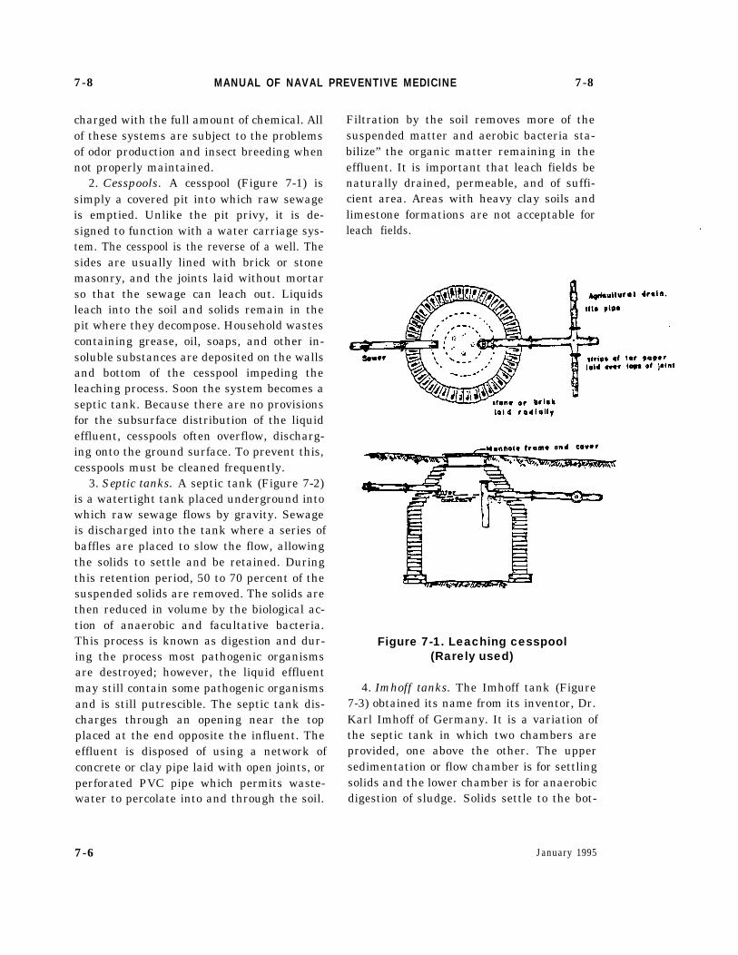
2. Cesspools. A cesspool (Figure 7-1) issimply a covered pit into which raw sewageis emptied. Unlike the pit privy, it is de-signed to function with a water carriage sys-tem. The cesspool is the reverse of a well. Thesides are usually lined with brick or stonemasonry, and the joints laid without mortarso that the sewage can leach out. Liquidsleach into the soil and solids remain in thepit where they decompose. Household wastescontaining grease, oil, soaps, and other in-soluble substances are deposited on the wallsand bottom of the cesspool impeding theleaching process. Soon the system becomes aseptic tank. Because there are no provisionsfor the subsurface distribution of the liquideffluent, cesspools often overflow, discharg-ing onto the ground surface. To prevent this,cesspools must be cleaned frequently.
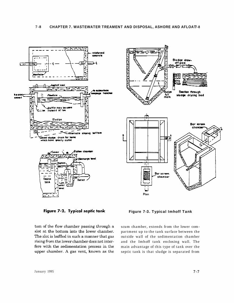
3. Septic tanks. A septic tank (Figure 7-2)is a watertight tank placed underground intowhich raw sewage flows by gravity. Sewageis discharged into the tank where a series ofbaffles are placed to slow the flow, allowingthe solids to settle and be retained. Duringthis retention period, 50 to 70 percent of thesuspended solids are removed. The solids arethen reduced in volume by the biological ac-tion of anaerobic and facultative bacteria.This process is known as digestion and dur-ing the process most pathogenic organismsare destroyed; however, the liquid effluentmay still contain some pathogenic organismsand is still putrescible. The septic tank dis-charges through an opening near the topplaced at the end opposite the influent. Theeffluent is disposed of using a network ofconcrete or clay pipe laid with open joints, orperforated PVC pipe which permits waste-water to percolate into and through the soil.
Filtration by the soil removes more of thesuspended matter and aerobic bacteria sta-bilize” the organic matter remaining in theeffluent. It is important that leach fields benaturally drained, permeable, and of suffi-cient area. Areas with heavy clay soils andlimestone formations are not acceptable forleach fields. .
Figure 7-1. Leaching cesspool(Rarely used)
4. Imhoff tanks. The Imhoff tank (Figure7-3) obtained its name from its inventor, Dr.Karl Imhoff of Germany. It is a variation ofthe septic tank in which two chambers areprovided, one above the other. The uppersedimentation or flow chamber is for settlingsolids and the lower chamber is for anaerobicdigestion of sludge. Solids settle to the bot-
January 19957-6
7-8 CHAPTER 7. WASTEWATER TREAMENT AND DISPOSAL, ASHORE AND AFLOAT 7-8
January 1995
Plan
Figure 7-3. Typical Imhoff Tank
scum chamber, extends from the lower com-partment up to the tank surface between theoutside wall of the sedimentation chamberand the Imhoff tank enclosing wall. Themain advantage of this type of tank over theseptic tank is that sludge is separated from
7-7
7-8 MANUAL OF NAVAL PREVENTIVE MEDICINE 7-9
the effluent, which allows for more completesettling and digestion. Operated properly,these systems are capable of removing 30 to60 percent of the suspended matter, andfrom 25 to 40 percent of the BOD.
5. Other Non-Sewered Waste DisposalSystems. This category of waste disposal sys-tems includes various portable or temporarytoilets such as chemical toilets, combustiontoilets, vaulted toilets and recirculating toi-lets. The standards for these devices mustnot be less than those established by theAmerican National Standards Institute, Inc.(ANSI) Z4.3-1979 “Minimum Requirementsfor Non-Water Carriage Disposal Systems”or its subsequent revisions.
7-9. Community WastewaterTreatment Systems
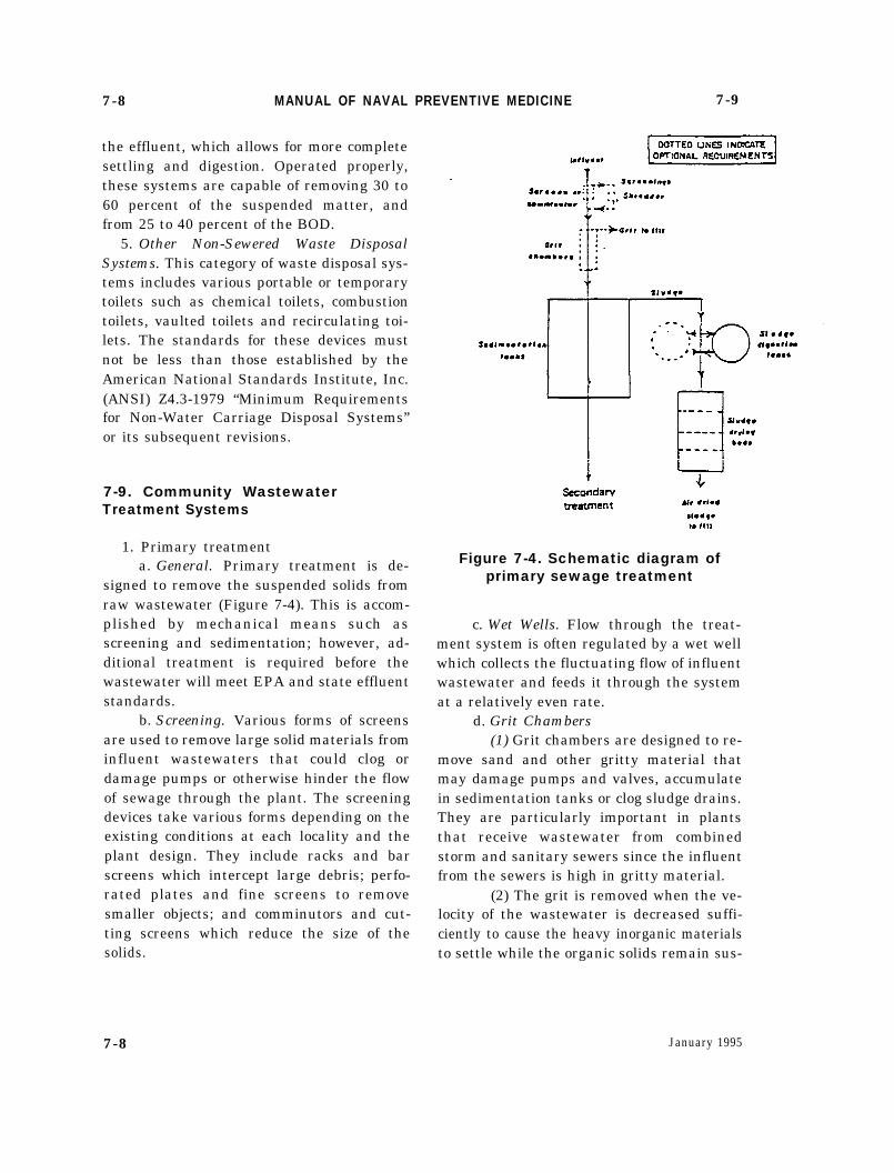
1. Primary treatmenta. General. Primary treatment is de-
signed to remove the suspended solids fromraw wastewater (Figure 7-4). This is accom-plished by mechanical means such asscreening and sedimentation; however, ad-ditional treatment is required before thewastewater will meet EPA and state effluentstandards.
b. Screening. Various forms of screensare used to remove large solid materials frominfluent wastewaters that could clog ordamage pumps or otherwise hinder the flowof sewage through the plant. The screeningdevices take various forms depending on theexisting conditions at each locality and theplant design. They include racks and barscreens which intercept large debris; perfo-rated plates and fine screens to removesmaller objects; and comminutors and cut-ting screens which reduce the size of thesolids.
Figure 7-4. Schematic diagram ofprimary sewage treatment
c. Wet Wells. Flow through the treat-ment system is often regulated by a wet wellwhich collects the fluctuating flow of influentwastewater and feeds it through the systemat a relatively even rate.
d. Grit Chambers(1) Grit chambers are designed to re-
move sand and other gritty material thatmay damage pumps and valves, accumulatein sedimentation tanks or clog sludge drains.They are particularly important in plantsthat receive wastewater from combinedstorm and sanitary sewers since the influentfrom the sewers is high in gritty material.
(2) The grit is removed when the ve-locity of the wastewater is decreased suffi-ciently to cause the heavy inorganic materialsto settle while the organic solids remain sus-
7-8 January 1995
7-9 CHAPTER 7. WASTEWATER TREAMENT AND DISPOSAL, ASHORE AND AFLOAT 7-9
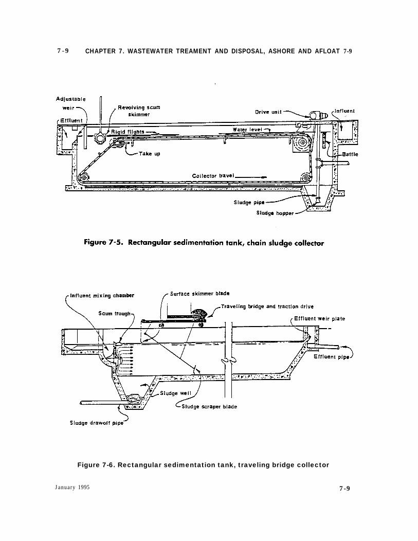
Figure 7-6. Rectangular sedimentation tank, traveling bridge collector
January 1995 7-9

7-9 MANUAL OF NAVAL PREVENTIVE MEDICINE 7-9
pended. There are usually two grit chambersarranged in parallel so that one remains inoperation while the other is cleaned.
(3) The accumulated grit is removedfrom the chamber either manually or me-chanically. The washed grit is relatively in-offensive and can be used in landfills.
e. Sedimentation Tanks.(1) Sedimentation involves removal
of a large part of the suspended solids fromraw wastewater. Sedimentation is used inboth primary and secondary treatment pro-cesses and, when employed in a primarytreatment process, is designated as “primarysedimentation .“
(2) Plain sedimentation and chemi-cal precipitation are two types of sedimenta-tion used in wastewater treatment operations.
(a) Plain sedimentation with sepa-rate sludge removal is a common practice. Theinfluent enters either a circular or rectangularsedimentation tank (Figures 7-5 and 7-6)where the flow rate is slowed and distributedevenly across the tank by a system of baffles,weirs, and multiple inlets. The slow even flowallows solids to settle to the bottom of the tankas sludge. The sludge is removed from thebottom of the sedimentation tank to a digesterthrough pipes under hydrostatic pressure orsuction. The sludge must be routinely removedin order to prevent its decomposition in thesedimentation tank resulting in the release ofgases to the surface which would hinder effec-tive settling and produce malodors.
(b) Chemical precipitation of waste-water is sometimes used to enhance the set-tling process. In this method chemicals such aslime, alum, ferrous sulfate, and/or ferric chlo-ride are added to the wastewater before itenters the sedimentation tank. As the chemi-cals mix with the wastewater they form an
insoluble gelatinous floe which settles rap-idly, carrying with it most of the suspendedsolids in the wastewater. This method ismost often used when industrial wastewa-ters are being treated.
(3) Mechanical skimming devices areinstalled on most sedimentation tanks to re-move scum and oil products which float onthe surface of the wastewater.
(4) The outlet weir of the sedimenta-tion tank extends across the full width ofrectangular sedimentation tanks andaround the periphery of circular ones to en-sure a smooth even flow. The effluent contin-ues on to secondary treatment or to finaldisposition.
f. Efficiency. Primary treatment re-moves only a portion of those substanceswhich are in the suspended state, leaving thecolloidal and dissolved substances in the liq-uid effluent. Between 40 to 75 percent of thesuspended matter is removed depending onthe concentration, the retention time in thesedimentation tank, and the evenness ofdistribution and flow in the tank. The BOD isreduced 30-40 percent.
2. Secondary Treatmenta. General. Secondary treatment in-
volves removal of most of the colloidal anddissolved organic materials in the wastewa-ter. This is usually accomplished underaerobic conditions by biological oxidative de-composition and production of biologicalgrowths that are removed in secondarysludge. Activated sludge, trickling filters,and stabilization ponds are most often usedto maintain aerobic conditions and the inti-mate contact between the wastewaters andorganisms necessary for the removal of thepollutants.
7-10 January 1995
7-9 CHAPTER 7. WASTEWATER TREAMENT AND DISPOSAL, ASHORE AND AFLOAT 7-9
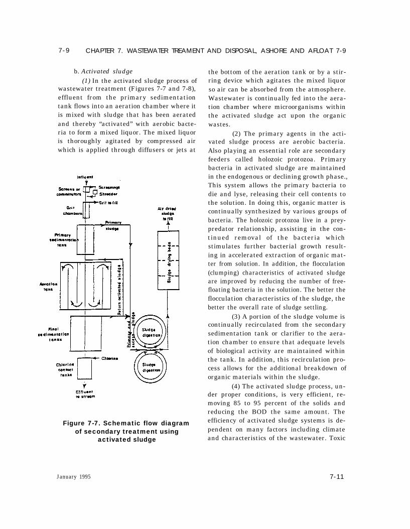
b. Activated sludge(1) In the activated sludge process of
wastewater treatment (Figures 7-7 and 7-8),effluent from the primary sedimentationtank flows into an aeration chamber where itis mixed with sludge that has been aeratedand thereby “activated” with aerobic bacte-ria to form a mixed liquor. The mixed liquoris thoroughly agitated by compressed airwhich is applied through diffusers or jets at
Figure 7-7. Schematic flow diagramof secondary treatment using
activated sludge
the bottom of the aeration tank or by a stir-ring device which agitates the mixed liquorso air can be absorbed from the atmosphere.Wastewater is continually fed into the aera-tion chamber where microorganisms withinthe activated sludge act upon the organicwastes.
(2) The primary agents in the acti-vated sludge process are aerobic bacteria.Also playing an essential role are secondaryfeeders called holozoic protozoa. Primarybacteria in activated sludge are maintainedin the endogenous or declining growth phase.,This system allows the primary bacteria todie and lyse, releasing their cell contents tothe solution. In doing this, organic matter iscontinually synthesized by various groups ofbacteria. The holozoic protozoa live in a prey-predator relationship, assisting in the con-tinued removal of the bacteria whichstimulates further bacterial growth result-ing in accelerated extraction of organic mat-ter from solution. In addition, the flocculation(clumping) characteristics of activated sludgeare improved by reducing the number of free-floating bacteria in the solution. The better theflocculation characteristics of the sludge, thebetter the overall rate of sludge settling.
(3) A portion of the sludge volume iscontinually recirculated from the secondarysedimentation tank or clarifier to the aera-tion chamber to ensure that adequate levelsof biological activity are maintained withinthe tank. In addition, this recirculation pro-cess allows for the additional breakdown oforganic materials within the sludge.
(4) The activated sludge process, un-der proper conditions, is very efficient, re-moving 85 to 95 percent of the solids andreducing the BOD the same amount. Theefficiency of activated sludge systems is de-pendent on many factors including climateand characteristics of the wastewater. Toxic
January 1995 7-11
7-9 MANUAL OF NAVAL PREVENTIVE MEDICINE 7-9
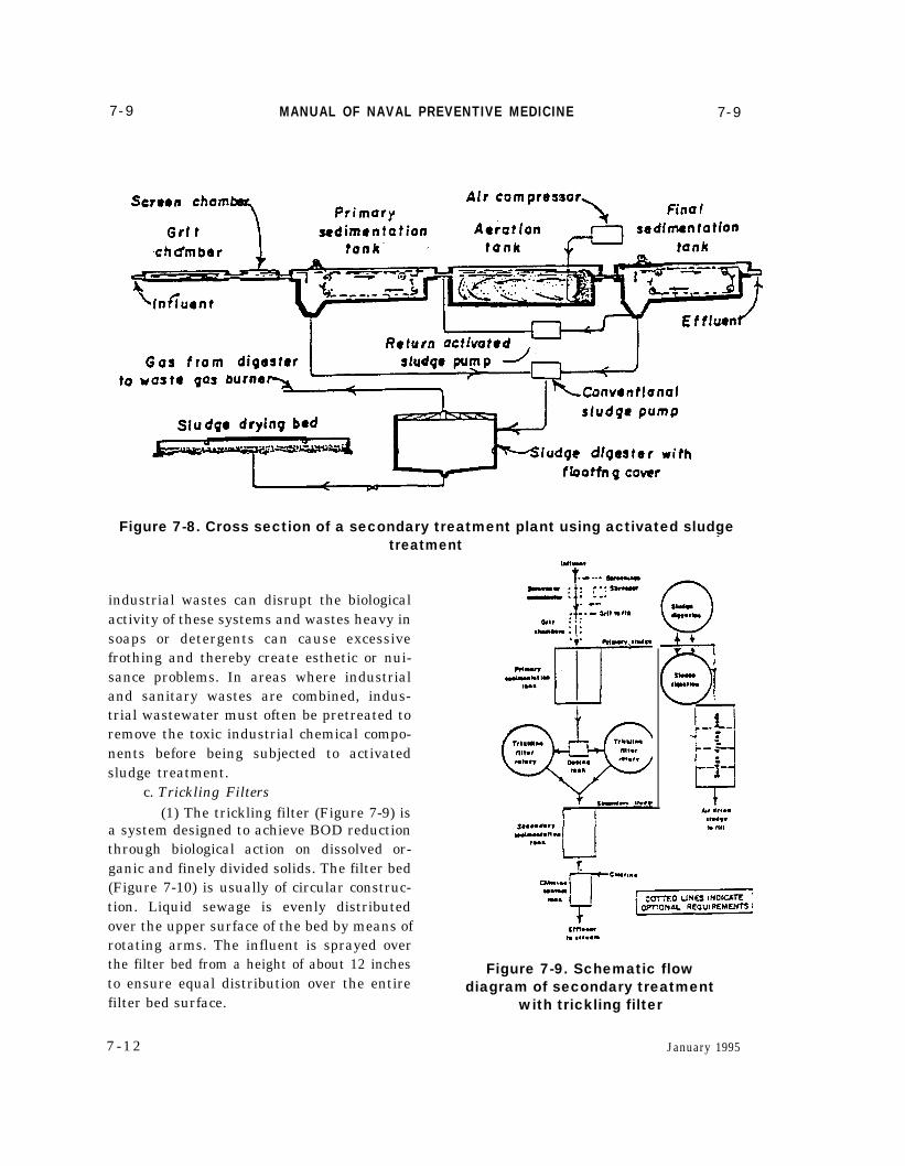
Figure 7-8. Cross section of a secondary treatment plant using activated sludge
industrial wastes can disrupt the biologicalactivity of these systems and wastes heavy insoaps or detergents can cause excessivefrothing and thereby create esthetic or nui-sance problems. In areas where industrialand sanitary wastes are combined, indus-trial wastewater must often be pretreated toremove the toxic industrial chemical compo-nents before being subjected to activatedsludge treatment.
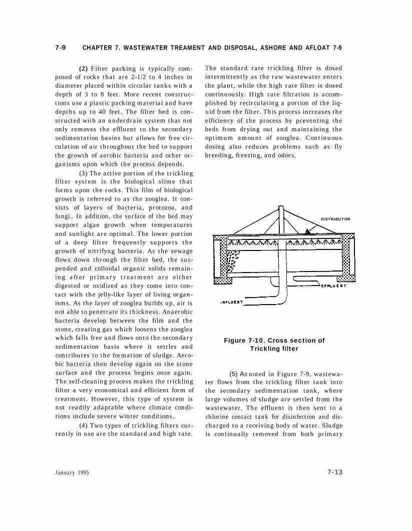
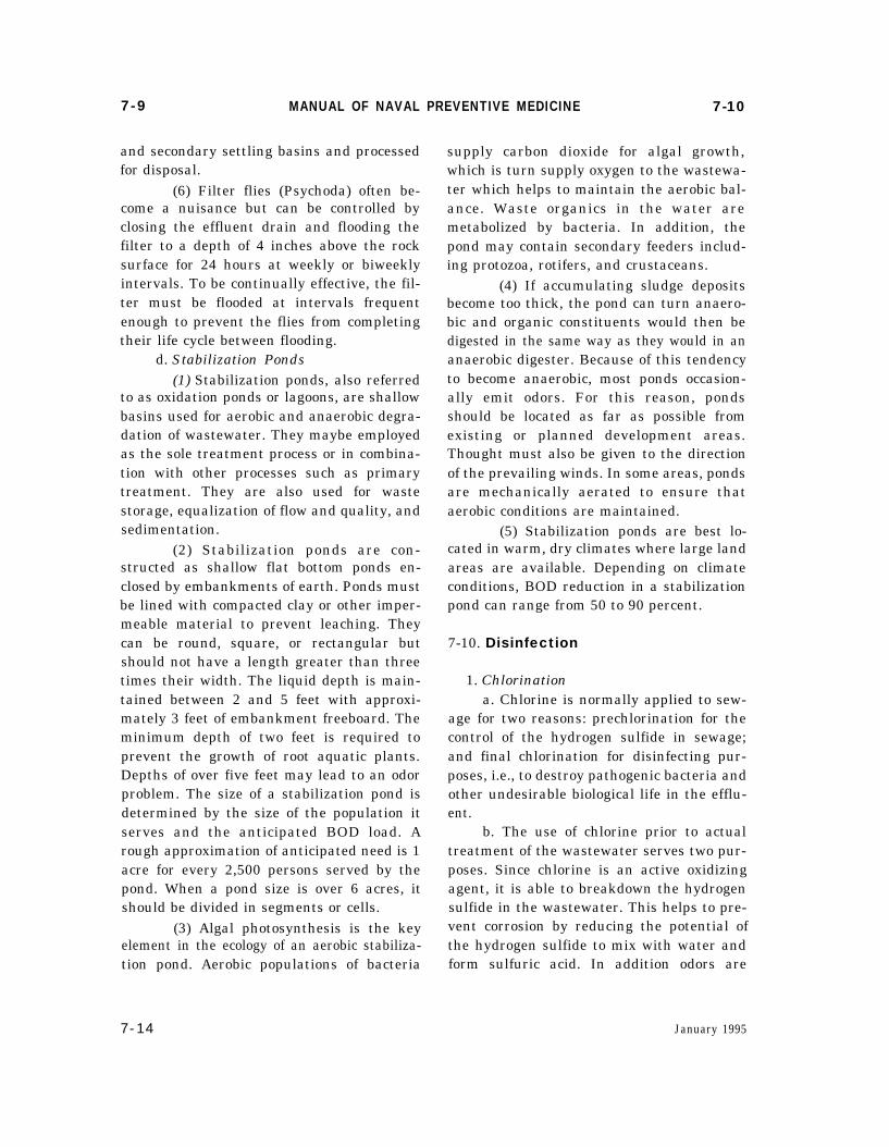
c. Trickling Filters(1) The trickling filter (Figure 7-9) is
a system designed to achieve BOD reductionthrough biological action on dissolved or-ganic and finely divided solids. The filter bed(Figure 7-10) is usually of circular construc-tion. Liquid sewage is evenly distributedover the upper surface of the bed by means ofrotating arms. The influent is sprayed overthe filter bed from a height of about 12 inchesto ensure equal distribution over the entirefilter bed surface.
7 -12
treatment
Figure 7-9. Schematic flowdiagram of secondary treatment
with trickling filter
January 1995
7-9 CHAPTER 7. WASTEWATER TREAMENT AND DISPOSAL, ASHORE AND AFLOAT 7-9
(2) Filter packing is typically com-posed of rocks that are 2-1/2 to 4 inches indiameter placed within circular tanks with adepth of 3 to 8 feet. More recent construc-tions use a plastic packing material and havedepths up to 40 feet. The filter bed is con-structed with an underdrain system that notonly removes the effluent to the secondarysedimentation basins but allows for free cir-culation of air throughout the bed to supportthe growth of aerobic bacteria and other or-ganisms upon which the process depends.
(3) The active portion of the tricklingfilter system is the biological slime thatforms upon the rocks. This film of biologicalgrowth is referred to as the zooglea. It con-sists of layers of bacteria, protozoa, andfungi.. In addition, the surface of the bed maysupport algae growth when temperaturesand sunlight are optimal. The lower portionof a deep filter frequently supports thegrowth of nitrifyng bacteria. As the sewageflows down through the filter bed, the sus-pended and colloidal organic solids remain-ing after primary treatment are eitherdigested or oxidized as they come into con-tact with the jelly-like layer of living organ-isms. As the layer of zooglea builds up, air isnot able to penetrate its thickness. Anaerobicbacteria develop between the film and thestone, creating gas which loosens the zoogleawhich falls free and flows onto the secondarysedimentation basis where it settles andcontributes to the formation of sludge. Aero-bic bacteria then develop again on the stonesurface and the process begins once again.The self-cleaning process makes the tricklingfilter a very economical and efficient form oftreatment. However, this type of system isnot readily adaptable where climate condi-tions include severe winter conditions.
(4) Two types of trickling filters cur-rently in use are the standard and high rate.
The standard rate trickling filter is dosedintermittently as the raw wastewater entersthe plant, while the high rate filter is dosedcontinuously. High rate filtration is accom-plished by recirculating a portion of the liq-uid from the filter. This process increases theefficiency of the process by preventing thebeds from drying out and maintaining theoptimum amount of zooglea. Continuousdosing also reduces problems such as flybreeding, freezing, and odors.
DiSTRIBUTOR
Figure 7-10. Cross section ofTrickling filter
(5) AS noted in Figure 7-9, wastewa-ter flows from the trickling filter tank intothe secondary sedimentation tank, wherelarge volumes of sludge are settled from thewastewater. The effluent is then sent to achlorine contact tank for disinfection and dis-charged to a receiving body of water. Sludgeis continually removed from both primary
January 1995 7-13
7-9 MANUAL OF NAVAL PREVENTIVE MEDICINE 7-10
and secondary settling basins and processedfor disposal.
(6) Filter flies (Psychoda) often be-come a nuisance but can be controlled byclosing the effluent drain and flooding thefilter to a depth of 4 inches above the rocksurface for 24 hours at weekly or biweeklyintervals. To be continually effective, the fil-ter must be flooded at intervals frequentenough to prevent the flies from completingtheir life cycle between flooding.
d. Stabilization Ponds(1) Stabilization ponds, also referred
to as oxidation ponds or lagoons, are shallowbasins used for aerobic and anaerobic degra-dation of wastewater. They maybe employedas the sole treatment process or in combina-tion with other processes such as primarytreatment. They are also used for wastestorage, equalization of flow and quality, andsedimentation.
(2) Stabilization ponds are con-structed as shallow flat bottom ponds en-closed by embankments of earth. Ponds mustbe lined with compacted clay or other imper-meable material to prevent leaching. Theycan be round, square, or rectangular butshould not have a length greater than threetimes their width. The liquid depth is main-tained between 2 and 5 feet with approxi-mately 3 feet of embankment freeboard. Theminimum depth of two feet is required toprevent the growth of root aquatic plants.Depths of over five feet may lead to an odorproblem. The size of a stabilization pond isdetermined by the size of the population itserves and the anticipated BOD load. Arough approximation of anticipated need is 1acre for every 2,500 persons served by thepond. When a pond size is over 6 acres, itshould be divided in segments or cells.
(3) Algal photosynthesis is the keyelement in the ecology of an aerobic stabiliza-tion pond. Aerobic populations of bacteria
supply carbon dioxide for algal growth,which is turn supply oxygen to the wastewa-ter which helps to maintain the aerobic bal-ance. Waste organics in the water aremetabolized by bacteria. In addition, thepond may contain secondary feeders includ-ing protozoa, rotifers, and crustaceans.
(4) If accumulating sludge depositsbecome too thick, the pond can turn anaero-bic and organic constituents would then bedigested in the same way as they would in ananaerobic digester. Because of this tendencyto become anaerobic, most ponds occasion-ally emit odors. For this reason, pondsshould be located as far as possible fromexisting or planned development areas.Thought must also be given to the directionof the prevailing winds. In some areas, pondsare mechanically aerated to ensure thataerobic conditions are maintained.
(5) Stabilization ponds are best lo-cated in warm, dry climates where large landareas are available. Depending on climateconditions, BOD reduction in a stabilizationpond can range from 50 to 90 percent.
7-10. Disinfection
1. Chlorinationa. Chlorine is normally applied to sew-
age for two reasons: prechlorination for thecontrol of the hydrogen sulfide in sewage;and final chlorination for disinfecting pur-poses, i.e., to destroy pathogenic bacteria andother undesirable biological life in the efflu-ent.
b. The use of chlorine prior to actualtreatment of the wastewater serves two pur-poses. Since chlorine is an active oxidizingagent, it is able to breakdown the hydrogensulfide in the wastewater. This helps to pre-vent corrosion by reducing the potential ofthe hydrogen sulfide to mix with water andform sulfuric acid. In addition odors are
7-14 January 1995
7-10 CHAPTER 7. WASTEWATER TREAMENT AND DISPOSAL, ASHORE AND AFLOAT
eliminated by the removal of hydrogen sul-fide. When prechlorination is employed, it isimportant that an excessive amount of chlo-rine is not used since the bactericidal actionof free residual chlorine may interfere withthe biological processes of the secondarytreatment system.
c. The bactericidal action of chlorine re-sults from its strong oxidizing power on thebacterial cell’s chemical structure, destroy-ing the enzymatic processes required for life.Disinfection of wastewater is defined as theaddition of sufficient chlorine so that a freechlorine residual of between 0.5 ppm and 0.7ppm exists after a 30 minute contact time.The amount of chlorine required to maintainthe residual varies greatly depending uponthe composition, temperature, and flow rateof the wastewater. Frequent monitoring andadjustment of chlorine flow is needed tomaintain uniform results.
2. Other chemicals are occasionally usedas disinfecting agents in wastewater treat-ment processes. These include bromine, io-dine, and ozone. However, these chemicalsare more often used in swimming pools, spasand/or for drinking water treatment. Chlo-rine is still the most effective way of disin-fecting domestic wastewater.
7-11. Advanced WastewaterTreatment
1. Generala. Advanced wastewater treatment
(AWT) refers to processes and methods thatare designed to remove more contaminantsfrom wastewater than are usually removedby conventional treatment operations. Theterm tertiary treatment is often used whendiscussing AWT, but the two are not pre-cisely the same in meaning. Tertiary sug-gests a single additional step in wastewatertreatment beyond secondary treatment. Ad-
7-11
vanced treatment means any process or sys-tem not now in common use or a system thatmay modify or replace one or more steps ofconventional treatment. An example of thiswould be the addition of chemicals in a con-ventional activated sludge process to pre-cipitate phosphorus.
b. As stricter water quality require-ments are placed on wastewater treatmentfacilities, advanced processes for wastewatertreatment are becoming more common. AWTsystems are used to remove additional BOD,suspended solids, nitrogen, phosphorus, andpathogenic bacteria. In addition, many fa-cilities that have industrial operations musttreat their wastes to remove heavy metals,dissolved solids, color or specific inorganicsubstances. The technology for performingadvanced wastewater treatment is changingrapidly. The basis systems presented hereare used with a wide variety of modificationand under an equal variety of conditions foradvanced wastewater treatment.
2. Chemical Coagulationa. Chemical coagulation is the process
in which a chemical agent is introduced intothe wastewater to help remove both organicand inorganic colloidal suspensions in thewaste. The colloids found in wastewaterconsist of discrete particles held in suspen-sion. Their extremely small size prohibitsthem from precipitating out of solution un-der normal circumstances. These particlesmay range in size from 1 to 200 nanometers.
b. There are two types of colloidal sus-pensions: hydrophilic and hydrophobic. Hy-drophilic colloids readily disperse in water.Their lack of tendency to agglomerate de-pends upon a marked affinity for water. Hy-drophilic colloids include soaps, solublestarch, and synthetic detergents. Hydropho-bic colloids possess no affinity for water andget stability from their inherent electricalcharges. This charge causes repulsion be-
January 1995 7-15
7-11 MANUAL OF NAVAL PREVENTIVE MEDICINE 7-11
ween particles and is referred to as the zetapotential. Metal oxide colloids are examplesof hydrophobic solutions.
c. For coagulation to occur, destabiliza-tion of the colloidal particles is necessary.Destabilization employs two mechanisms.The addition of electrolytes in solution re-duces the net electrical repulsive force at theparticle surfaces. Flocculation facilitatesbridging between particles.
d. There are two operations involved inthe coagulation process. Mixing is the pro-cess wherein a dissolved coagulant materialis rapidly dispersed with violent agitationthroughout the water being treated. Floccu-lation involves the continuous agitation ofwastewater at much slower velocities to al-low for the agglomeration of very small par-ticles into well defined floes that settlereadily.
e. The most widely used coagulant forwastewater treatment are aluminum andiron salts. Waters high in organic matter arebest treated with aluminum sulfate. Ferriccompounds are useful in removing odor prob-lems. Aluminum sulfate and ferric chlorideare the coagulant of choice for the chemicalcoagulation of phosphorus from wastewater.
f. In many cases, coagulant aids are alsoadded to the mixing tanks to adjust the pH ofthe solution to optimize coagulation. Coagu-lant aids include activated silica, polyelectro-lyte compounds, and clay.
g. Coagulation processes are most oftencarried out in the secondary sedimentationchamber.
3. Biological Vitrification and De-nitrification
a. Biological vitrification is the processby which ammonia nitrogen (NH3) is con-verted to nitrate (NO3). Vitrification does not
remove the nitrogen but only changes itsform. Removal of the ammonia eliminatesthe demand for oxygen and the resultingproblem of ammonia toxicity. This oxygen re-quirement is often referred to as the nitrog-enous oxygen demand (NOD).
b. Two groups of bacteria are re-sponsible for carrying out the vitrificationprocess. They are Nitrosomonas a n dNitrobacter, both of which grow aerobicallyby obtaining carbon from inorganic sourcessuch as carbon dioxide (CO2). These nitriry-ing bacteria are present to some extent in alltypes of aerobic waste treatment procedures.Their growth rate, however, is very slowwhen compared to bacteria which are BODremovers. In order “to foster the vitrificationprocess, long detention times are needed (24hours), the mixed liquor suspended solidsconcentration must be high, the sludge mustbe well aged, and wastewater temperaturehas to be maintained above 12°C.
c. Vitrification can be accomplished inone or two stage systems. In a single stagesystem, BOD reduction and vitrification oc-cur simultaneously during an extended aera-tion activated sludge process. Two-stagevitrification requires separate aerationchambers for BOD removal and vitrification.This system is most successful for treatmentof waste with high ammonia concentrations.
d. In some areas, nitrate can be safelydischarged in the effluent. However, if this isnot allowable, the denitrification processmust be undertaken. Denitrification refers tothe biological process of reducing nitrate(NO3) to nitrite (NO2) and then to nitrogengas. This is accomplished under anaerobicconditions by facultative bacteria in the pres-ence of biodegradable organic matter. Thenitrate ion serves as an oxidizing agent andis reduced to nitrogen gas in the process.
7-16 January 1995
7-11 CHAPTER 7. WASTEWATER TREAMENT AND DISPOSAL, ASHORE AND AFLOAT
e. To achieve a satisfactory rate of deni-trification, the nitrogen must be in the ni-trate (NO3) or nitrite (NO2) form; thereshould be no dissolved oxygen present; andthere must be some BOD present to drive theprocess. Temperature control is essentialsince the rate of reaction falls off proportion-ally to a decrease in temperature.
f. Three systems are presently used forthe denitrification process. They includeanaerobic ponds, anaerobic sludge andanaerobic filters.
4. Ammonia Strippinga. Water soluble ammonium ions exist
in wastewater solutions in equilibrium withammonia gas. If the pH of a wastewatersolution is raised to a value of 10.5, the equi-librium is shifted in favor of ammonia gascausing it to be formed. In order to accom-plish this shift, lime is usually added towastewater streams to adjust the pH. Am-monia gas may then be removed from thewastewater by stripping with air, as thewaste is passed through a slot filled coolingtower equipped with an air blower. Thewastewater is allowed to enter the top of thecooling tower at a rate of 1 to 4 gallons perminute per square foot of tower. As the waterflows through the packing, air is injected intothe system countercurrent to the water. Theammonia gas is subsequently striped fromwastewater.
b. When proper balance between pH,air flow rate, tower depth, temperature, andhydraulic loading is maintained, 90 percentof the ammonia can be removed. After strip-ping is completed, the pH of the effluent isreadjusted in order to conform to local efflu-ent standards.
7-11
5. Filtration and Microscreeninga. Filtration is used for removal of finely
divided suspended material after an effluenthas been subjected to secondary clarificationor chemical precipitation units. In removingthe suspended matter, filtration helps to sig-nificantly reduce phosphates, COD, andBOD.
b. Filtration can be accomplished by us-ing filter beds made of diatomaceous earth,sand or mixed media. Wastewater flowsthrough the filter bed where suspended sol-ids are entrapped. After a period of opera-tion, flow through the filter is obstructed bythe entrapped material. When this occurs,the filter must be taken off line andbackwashes before filtration can continue. Ifthis cleaning is not completed, short-circuit-ing within the filter bed may occur, resultingin poor effluent quality. Filtration canachieve suspended solid values of 1 to 20milligrams per liter depending on the effi-ciency of biological processes that precededit.
c. A microstrainer can also be used toprovide the same results achieved by a filterbed. A microstrainer is a screen in the form ofa partially submerged rotating drum. Influ-ent wastewater enters the inside of the drumfrom one end and flows out through the fil-tering screen depositing solids on the innersurface of the screen. The screen is continu-ally washed and the solids are collected andreturned to the beginning of the treatmentsystem. Pore size in a microstrainer is be-tween 50 and 60 micrometers. The flow rateis maintained between 5 and 10 gallons perminute per, square foot of submergedscreen. One major disadvantage of themicrostraining technique is the occasional
January 1995 7-17
7-11 MANUAL OF NAVAL PREVENTIVE MEDICINE 7-11
buildup of grease and biological growth(slime). Extensive and frequent cleaning ofmircostraining equipment is required to con-trol these problems.
6. Ion Exchange.Ion exchange is the exchange of one
type of electrically charged particle for a dif-ferent type. A solid material containing ex-changeable ions is placed in a bed or columnand the wastewater to be treated is thenpassed through it. Ion exchange systems areused to soften water, selectively remove spe-cific impurities, and recover valuable chemi-cals lost in industrial waste discharges.Specific applications include the recovery ofcalcium and magnesium ions from solutionsby exchanging them with sodium ions inbeds of sodium zeolite, and the removal ofammonia by the use of a natural occurringzeolite material called clinoptilolite. Syn-thetic organic cation (positively chargedions) exchanges are available for capturingsodium, potassium, calcium, and magnesiumions. Ion exchange beds have a limited ca-pacity. When the number of ions availablefor exchange are used up, the system or bedmust be regenerated; that is, treated to re-store the ion exchange capacity.
7. Activated Carbona. Activated carbon treatment is used to
remove refractory soluble organics not re-moved by coagulation. These substances in-clude nonbiodegradable organics, color,COD, and odor producing compounds andother organics. Adsorption by means of acti-vated carbon can be accomplished in twoways. Powered carbon can be added to asedimentation basin where it is mixed, floc-culated, and settled from the waste. Morefrequently, activated carbon columns orcounter flow beds are used. Removal of the
organics occurs by adsorption of the less po-lar molecules, filtration of large particles,and deposition of colloidal material. The de-gree of waste removal is controlled by thelength of contact time between the carbonand the water.
b. Carbon used in the activated carbonsystem is generated by high temperatureactivation of coal. Activation results in theformation of a network of microporesthroughout the carbon which gives it adsorp-tive characteristics. As the carbon loses itsadsorptive and filtering capacity, an increasein the COD of the wastewater is noted. Thespent carbon is then regenerated.
c. Carbon removed from a column orbed for regeneration is first dewatered andthen placed in a multiple-hearth furnace.The activated carbon is thermally regener-ated by heating to a temperature of 1500 to1700” F where adsorbed impurities are vola-tilized and released in a gaseous form. Ap-proximately 10 percent of the carbon is lostper regeneration cycle.
8. Land Applicationa. In some remote areas, wastewaters
are disposed of by means of land application.In these projects, wastewaters are run ontograsslands and plowed fields or channeled bymeans of irrigation systems. These areas areoften referred to as sewage farms. The use ofwastewater for these purposes provides ben-efit from the water and the fertilizing com-ponents of the waste. When using primaryeffluent, attempts must be made to limit di-rect contact with crops. Sewage farms are ararity in the U.S.
b. In some instances, secondary effluentof high quality can be used for irrigation andspray purposes. The use of water for thesepurposes is controlled by the effluent stan-dards and disposal criteria established by
7-18 January 1995
7-11 CHAPTER 7. WASTEWATER TREAMENT AND DISPOSAL, ASHORE AND AFLOAT 7-12
the state government. Any projects involvingland application or reuse of wastewater ef-f luent must be coordinated throughNAVFACENGCOM Engineering Field Divi-sions and BUMED.
7-12. Sludge Digestion and Disposal
1. General. Primary treatment of domesticwastewater creates a sludge which containsapproximately 65 percent organic material.The bulk of this sludge is composed of thesolids settled from the wastewater. Secondarytreatment sludge contains about ,90 percentorganic material. Advanced wastewater treat-ment methods create a sludge composed ofeither a chemical or biological waste, depend-ing upon the composition of the wastewaterand the treatment procedure used. Before ul-timate disposal of sludge can occur, it must berendered innocuous. Therefore, most sludgesare subjected to digestion processes prior toterminal disposal. The intention of sludge di-gestion is to convert the bulky odorous andputrescible waste into a well digested sludgewhich can be easily dewatered and is rela-tively odor free.
2. Anaerobic Digestiona. In an anaerobic digestion process, the
organic matter in the waste sludge is de-composed in the absence of molecular oxy-gen. The end products of anaerobicdecomposition are methane gas (CH4), car-bon dioxide (C02), unused intermediate or-ganics, and a small amount of cellularprotoplasm.
b. There are two main groups of micro-organisms responsible for anaerobic diges-tion. These are bacteria from the acid-forminggroup and the methane-forming group. Theacid-formers convert the complex organicmatter to low-molecular weight fatty acids
such as acetic, propionic, and butyric acids,also known as volatile acids. The methaneforming bacteria convert the volatile acids tomethane and carbon dioxide. This is a simul-taneous process dependent upon a carefullycontrolled environment within the digester.Any shift in the delicate balance will result in adecrease of the efficiency of the system.Anaerobic digester failure can result from asudden increase in organic loading, a sharpdecrease in digestive sludge volume, an in-crease or decrease in the temperature or thepresence of an inhibitory substance.
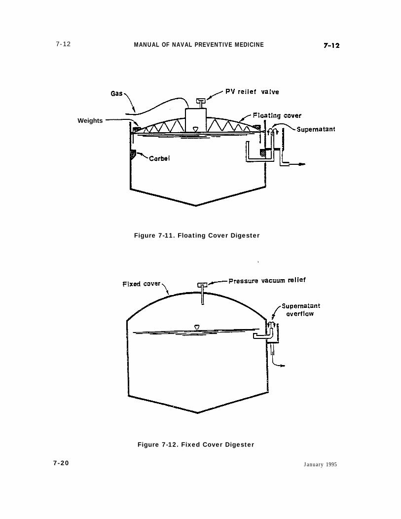
c. Anaerobic digesters are large cylindri-cal tanks with bottoms sloping toward thecenter so that the sand, grit, and heavy sludgecan be removed. In early construction, digest-ers were not covered; however, today most di-gesters have either a floating top (Figure 7-11)or a fixed cover (Figure 7-12). Most digestersare equipped with heaters to help maintainadequate sludge temperatures within thetank.
d. It is most important that air not beallowed into the digester. In a fixed coversystem, new sludge must be added to thesystem every time the finished sludge isdrawn off. The floating lid digester moves upand down with the tank level and the gaspressure.
e. The gasification process producesabout one cubic foot of the per capita per day.The gas contains approximately 2/3 methaneand 1/3 carbon dioxide. In many areas themethane produced by anaerobic digestion isused as fuel for the treatment plant. It can beused to heat the digester, or used in theoverall plant heating system. Some plantsuse the methane as incinerator fuel or ininternal combustion engines to run pumpsand compressors.
f. There are two principle classificationsof digesters; conventional (standard rate)
January 1995 7-19
7-12
Weights
MANUAL OF NAVAL PREVENTIVE MEDICINE
Figure 7-11. Floating Cover Digester
Figure 7-12. Fixed Cover Digester
7-20 January 1995
7-12 CHAPTER 7. WASTEWATER TREAMENT AND DISPOSAL, ASHORE AND AFLOAT 7-12
and high rate digesters. The primary differ-ence between the two systems is that thehigh-rate or two-stage system has a mixingtank or cycle which allows for higher loadingrates and continuous feeding and with-drawal of sludge. Detention time in the con-ventional digester is 30 to 90 days, while thehigh-rate unit has a detention period of 10 to20 days.
g. A liquid layer is formed during thedigestive process. This layer is referred to asthe supernatant. It contains a high concen-tration of organics and is rich in nitrogen andphosphorus. It must be returned to thewastewater treatment cycle at a point whereit will have the least effect.
3. Aerobic Digestiona. Aerobic digestion is another biologi-
cal process for treating organic waste sludgesprior to terminal disposal. In this system,waste sludge is subjected to extended aera-tion for a period of 12 to 25 days. During thistime, the microorganisms in the sludgebreak down the organic material. As thesupply of nutrients in the sludge decreases,the organisms consume their own cell mate-rial and reduce the organic content evenfurther.
b. Aerobic digestion is accomplished inone or more tanks mixed by diffused aera-tion. Multi-stage systems use the first tanksto accomplish most of the digestion. The laststage is used for solids concentration. A su-pernatant is produced during this step andmust be recycled.
c. The major advantages to aerobicsludge digestion include the production of amore stable sludge, fewer odor problems, andno safety problems related to the productionof methane and carbon dioxide. However,aerobic digestion produces a sludge which isdifficult to thicken, resulting in disposalproblems.
4. Sludge Conditioning, Dewatering, andFinal Disposition
a. Sludge handling and disposal is amajor part of the wastewater cycle. Evenafter digestion, sludge handling and disposalis difficult because of the water which is stilla major part of the overall sludge volume.
b. Sludges are often conditioned for sub-sequent dewatenng or disposal. Thickening,elutriation, and chemical coagulation are con-ditioning steps used prior to dewatering.
(1) In the thickening process, thesludge is placed in specifically designedtanks. The sludge is continuously stirred forperiods of 6 to 24 hours, during which timethe supernatant water is continually drawnoff. The continual stirring dislodges gasbubbles, prevents bridging of sludge solids,and keeps the sludge moving toward thecenter well of the tank. The thickening pro-cess usually doubles the sludge concentra-tion.
(2) Elutriation is the process bywhich a digested sludge is washed prior tofurther conditioning. The process involvesthe extraction of alkaline carbonate, phos-phates, and fine sludge particles from thesludge. The alkalinity is removed to reducethe amount of coagulant necessary for me-chanical dewatering. Elutriation is carriedout in tanks similar to sedimentation tanks.Rapid mixing of sludge and washwater iscarried out just prior to entering the sedi-mentation tanks.
(3) Sludge is often chemically treatedprior to undergoing the dewatering process.The addition of certain chemicals helps tobring about coagulation of the solids and alsoproduces a more rapid release of the waterfrom the sludge. Chemicals used in this pro-cess include lime, ferric chloride, ferric sul-fate, alum, and organic polymers.
c. Dewatering reduces the moisture con-tent of the sludge so that it can be handled
January 1995 7-21
7-12 MANUAL OF NAVAL PREVENTIVE MEDICINE 7-12
and disposed of in a solid form rather than asa liquid. The three principal methods of de-watering sludge are drying beds, vacuumfiltration, and centrifugation.
(1) Sludge drying beds are usedwhere the sewage plant flow is limited andland is available. The beds are composed of agravel bed covered with a layer of sand be-tween 6 and 12 inches in depth. A tileunderdrain system is often placed under thegravel bed to improve water removal. Thebed area is divided into cells of approxi-mately 20 by 50 feet. The sludge is drawn offfrom the digester and poured into the bed.Sludge is poured to a depth of 8 to 10 inches.The dewatering of sludge is due to drainageand evaporation. The major portion of sludgedrying is accomplished in the first 3 to 5days. Drying times depend on the initial wa-ter content and weather conditions, and mayrange from one to three weeks. Using sludgebeds, it is possible to obtain a sludge watercontent of approximately 25%.
(2) Vacuum filters are used forsludge dewatering at medium to large sizetreatment plants where large land areas arenot available for sludge drying beds. Vacuumfilters can also be used to handle raw sludgethat has not been digested. The vacuum fil-ter consists of a large drum on which a filtermedia has been placed. This media can bemade of cloth, synthetic fiber, stainless steelmesh or coil springs. The drum rotates sothat approximately 1/4 of it is submerged inthe sludge. Vacuum pressure applied to thedrum causes sludge to cake on the drumsurface. As the drum rotates, the water isdrawn from the sludge by the vacuum. Thedewatered sludge is then scraped off the fil-ter and collected in a hopper. Moisture con-tent of the dewatered sludge is approximately60-75 percent.
(3) Treatment plants handling largevolumes of waste material may use a centri-
fuge for dewatering sludge. Centrifugesseparate solids from the liquid by sedimen-tation and centrifugal force. Sludge for cen-trifugation is usually chemically conditionedprior to being dewatered. The sludge pro-duced in the use of the centrifuge has a watercontent of between 65 and 75 percent.
d. After the solids produced in wastewa-ter treatment operations are stabilized andreduce in volume, the problem of terminal dis-posal still remains. The only acceptable dis-posal alternative is disposal on land.
e. Sludge lagoons are a long-termmethod of storing sludge and are used wherethere is a large land area available. Lagoonsare natural or artificial basins with an aver-age depth of 4 to 10 feet that are lined withclay or other impermeable material. Di-gested sludge, when placed in a lagoon, willcontinue to dewater by means of evapora-tion. Liquid that settles to the bottom of thebeds must be collected by a leachate controlsystem and transported off site for furthertreatment or disposal. After lagoons havefilled up and the sludge has completely dried,the lagoon can be dug out and the sludgeresidue used for fill. Sludge which has beenpoorly digested may create an odor problem.
f. Sludge that has been dried on bedscan be successfully disposed of on land. Insome areas, liquid sludge that has not beendigested is poured directly onto the groundfrom tank trucks. This can be very beneficialto the soil, however, one must be made awareof the possible health hazards. Raw sludgemust be carefully monitored since thissludge may contain considerable quantitiesof disease producing organisms. It should notbe used as a general soil conditioner or fertil-izer if people are to be in contact with it. Thearea that has raw sludge disposed on itshould not be used for root crops or low grow-ing vegetables that may be eaten raw. Particu-lar attention should also be given to ground
7-22 January 1995
7-12 CHAPTER 7. WASTEWATER TREAMENT AND DISPOSAL, ASHORE AND AFLOAT 7-15
water and surface water runoff. Special careand attention should be given to sludges con-taining high concentrations of heavy metals.These types of sludge wastes must not be dis-posed of in an agriculture setting.
g. Disposal of dewatered sludge in aproperly run sanitary landfill is one of the bestdisposal methods available. Since the sludgeis buried and covered with a layer of soil,nuisance conditions are kept to a minimum.
7-13. Industrial WastewaterTreatment and Disposal
1. The character of industrial wastewatervaries as widely as industrial processes. In-dustrial wastes include organic chemicals,such as phenols and chlorinated hydrocar-bons; corrosive wastes, including acids andalkalies; toxic chemicals, such as cyanideand heavy metals; greases and oils; radioac-tive wastes, thermal pollution, and manyothers. Many of these industrial wastes canbe very disruptive to domestic wastewatertreatment systems by inhibiting or other-wise interfering with the treatment pro-cesses and causing major sludge handlingand disposal problems. In addition, thesewastewaters can adversely affect the qualityof the receiving waters into which they aredischarged.
2. Problems concerning the treatment anddisposal of industrial wastewaters at Navyand Marine Corps facilities must be broughtto the attention of the public works officer orthe responsible NAVFACENGCOM Engi-neering Field Division.
7-14. Health Precautions forWastewater Treatment SystemPersonnel
1. This section provides information re-garding health precautions and other pre-
ventive measures recommended for person-nel who work with wastewater treatmentsystems.
2. Those personnel who are in contactwith wastewater, or who work in or inspectwastewater treatment plants, must keeptheir basic immunizations current. Immuni-zations required include polio, tetanus, anddiphtheria.
3. Wastewater treatment plant personnelmust not eat, drink, or smoke when per-forming maintenance on or inspectingequipment which may be a direct source ofcontamination.
4. In the event of a significant wastewaterspill, those cleaning the area must wear cov-eralls, rubber boots, rubber gloves, hair cov-erings, and face shields. Upon completion ofspill clean-up, contaminated clothing mustbe removed and placed in a plastic bag forlaundering. Clean-up personnel must take ahot shower, using plenty of soap and water,promptly after spill clean-up is completed.Caution must be exercised when cleaningsewage spills in confined spaces. The gasesgiven off by sewage can be explosive, toxicand/or displace the oxygen in the space.
5. Clean-up of wastewater spills may beaccomplished using detergent and water,followed by thorough rinsing. Disinfection ofthe spill area is required in food service,berthing, and medical spaces. Disinfectionmay also be helpful in preventing odors inother areas. Recommended disinfectants arelisted in Article 7-20.
6. In the event of a major leak or spill, thecognizant medical department must be noti-fied.
7-15. Medical DepartmentResponsibilities
1. Cognizant medical department represen-tatives must periodically inspect wastewatertreatment facilities in order to detect potential
January 1995 7-23
7-15 MANUAL OF NAVAL PREVENTIVE MEDICINE 7-16
health hazards to operators and the sur- dence among treatment plant operators orrounding community. members of the surrounding community
2. Medical department representatives which may be attributed to exposure to hu-must be alert to any increase in disease inci- man wastes.
Section Ill. WASTEWATER TREATMENT AND DISPOSAL AFLOAT
ArticleIntroduction ------------------------------------------------------------------------------------------------- 7-16Marine Sanitation Device Systems Descriptions ------------------------------------------------- 7-17Inspection of Marine Sanitation Devices ------------------------------------------------------------ 7-18Ship-to-Shore Sewage Transfer ------------------------------------------------------------------------ 7-19Personal Hygiene, Sanitation, and Safety ---------------------------------------------------------- 7-20Medical Department Responsibilities -----------------------------------------------:---------------- 7-21Safety and Health Hazards of CHT Systems ------------------------------------------------------ 7-22CHT Pump Room Safety --------------------------------------------------------------------------------- 7-23
7-16. Introduction
1. The overboard discharge of untreatedsewage within the navigable waters of theU.S. and territorial seas (within 3 nauticalmiles of shore) is prohibited. Navy vesselsare equipped with marine sanitation devices(MSDS) which either treat sewage before dis-charge, or ‘collect and hold it until it can beproperly disposed of through dockside sewerconnections or pumped overboard in unre-stricted waters.
2. MSDS on Navy ships increase the poten-tial for contamination of berthing and workingspaces with raw sewage. Therefore, themedical department representative (MDR)must be familiar with the sewage disposalsystem and the procedures necessary to en-sure the health and safety of the ship’s crew.
3. There are three different types of marinesanitation devices including zero dischargesystems with full volume flush (FVF), zerodischarge systems with controlled volumeflush (CVF) and flow through treatment sys-tems.
a. The zero discharge system with FVFis a system which uses a standard 3-5 gallonflush and is able to store sewage in holdingtanks until it can be properly discharged.The Collection Holding and Transfer (CHT)System is a zero discharge, FVF system.
b. Zero discharge systems with CVFcollect, treat, and/or store sewage from toi-lets and urinals until it can be properly dis-charged over the side or otherwise disposedof through dockside facilities. They differfrom the FVF system in that they minimizethe volume of wastewater. This is accom-plished in various ways including reductionof the flushing medium followed by evapora-tion of the excess water, using a controlledvolume vacuum flush system and incinerat-ing the wastes, or recirculating the flushingmedium. Examples of this type system in-clude the GATX Evaporative Toilet System,the JERED VACU-BURN System and theKOELHER-DAYTON Recirculating FlushSystem. Some newer ship classes (e.g., DDG51) use a vacuum collection CVF systemwithout incineration.
7-24 January 1995
7-16 CHAPTER 7. WASTEWATER TREAMENT AND DISPOSAL, ASHORE AND AFLOAT 7-17
c. The flow through treatment systemtreats wastewater to acceptable limits anddischarges the effluent into receiving waters.The Pall-Trinity Biological Treatment Sys-tem is the only example of this type currentlyauthorized.
7-17. Marine Sanitation DeviceSystems Descriptions
1. Collection Holding and Transfer Sys-tem
a. CHT systems have been installed onthe majority of Navy ships. The systems aredesigned to operate in three modes; in re-stricted waters, sewage is collected andstored in holding tanks while gray water isdischarged overboard via diverter valves; atsea, all sewage and gray water, includingany stored in the holding tanks, is divertedor discharged overboard; and in port, sewageand gray water are collected in holding tanksand discharged into a sanitary sewer or shipwaste off-load barge (SWOB).
b. The CHT system is composed of threefictional elements:
(1) The collection element consistingof soil drains (from toilets and urinals), graywaters drains (from showers, laundries, andgalleys) and diverter valves which direct thewastewater over the side or to the holdingtanks.
(2) The holding element, consistingof tanks, retains sewage during transit ofrestricted waters for eventual disposal.These tanks are normally sized for a 12-hourholding period depending on individual shipconstraints. Holding tanks of 2,000 gallon(Figure 7-13) capacity and over are designedwith comminutors to macerate solids pass-ing into the tanks and an aeration system toprevent sludge from settling and becominganaerobic. Smaller tanks, on the other hand,
(Figure 7-14) incorporate strainers whichprevent solids from entering tanks.
(3) The transfer element includessewage pumps, overboard and deck connec-tion discharge piping and associated divertervalves and check valves. Each tank isequipped with two sewage pumps which areconnected in parallel to discharge sewageand gray water to a receiving facility, SWOB,or directly overboard.
c. The CHT system can be operated in amanual mode in which the pumps are actu-ated independent of the level of wastewaterin the holding tanks or in a fully automaticmode. When operating in a manual mode, anoption is available which will deactivate thepumps automatically when the low liquidlevel of the tanks reaches approximately10% of the tank volume in order to maintainpump suction. In the fully automatic mode,the following functions are accomplished:
(1) Duty pump alternation.(2) The low liquid level stops the
pump when the level reaches approximately10% of its capacity in order to keep thepumps primed.
(3) At 30% liquid level, a sensor sig-nals the duty pump to activate.
(4) At 60% liquid level, a sensor sig-nals the standby pump to activate.
(5) At 80% liquid level, a visual andaudible high level alarm is activated.
2. GATX Evaporative Toilet Systema. This system is a modular system
suitable for small vessels. It is designed tooperate in two modes. In restricted waters,the volume of wastewater generated is mini-mized by a reduction in flushing mediumusing CVF water closets and urinals. In re-stricted waters, the liquid portion of thewastewater is vaporized leaving a concen-trated sludge residue which can be stored for
January 1995 7-25
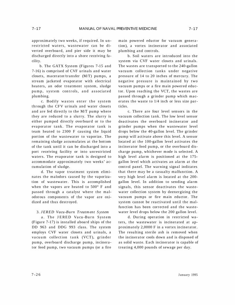
7-17 MANUAL OF NAVAL PREVENTIVE MEDICINE 7-17
approximately two weeks, if required. In un-restricted waters, wastewater can be di-verted overboard, and pier side it may bedischarged directly into a shore receiving fa-cility.
b. The GATX System (Figures 7-15 and7-16) is comprised of CVF urinals and waterclosets, macerator/transfer (M/T) pumps, astream jacketed evaporator with electricalheaters, an odor treatment system, sludgepump, system controls, and associatedplumbing.
c. Bodily wastes enter the systemthrough the CFV urinals and water closetsand are fed directly to the M/T pump wherethey are reduced to a slurry. The slurry iseither pumped directly overboard or to theevaporator tank. The evaporator tank isteam heated to 2300 F causing the liquidportion of the wastewater to vaporize. Theremaining sludge accumulates at the bottomof the tank until it can be discharged into aport receiving facility or into unrestrictedwaters. The evaporator tank is designed toaccommodate approximately two weeks’ ac-cumulation of sludge.
d. The vapor treatment system elimi-nates the malodors caused by the vaporiza-tion of wastewater. This is accomplishedwhen the vapors are heated to 500° F andpassed through a catalyst where the mal-odorous components of the vapor are oxi-dized and thus destroyed.
3. JERED Vacu-Burn Treatment Systema. The JERED Vacu-Burn System
(Figure 7-17) is installed aboard ships of theDD 963 and DDG 993 class. The systememploys CVF water closets and urinals, avacuum collection tank (VCT), grinderpump, overboard discharge pump, incinera-tor feed pump, two vacuum pumps (or a fire
7 -26
main powered eductor for vacuum genera-tion), a vortex incinerator and associatedplumbing and controls.
b. Soil waters are introduced into thesystem via CVF water closets and urinals.The wastes are transported to the 240-gallonvacuum collection tanks under negativepressure of 14 to 20 inches of mercury. Thenegative pressure is maintained by twovacuum pumps or a fire main powered educ-tor. Upon reaching the VCT, the wastes arepassed through a grinder pump which mac-erates the waste to 1/4 inch or less size par-ticles.
c. There are four level sensors in thevacuum collection tank. The low level sensordeactivates the overboard incinerator andgrinder pumps when the wastewater leveldrops below the 40-gallon level. The grinderpump will activate above this level. A sensorlocated at the 100-gallon level activates theincinerator feed pump, or the overboard dis-charge pump, whichever mode is selected. Ahigh level alarm is positioned at the 175-gallon level which activates an alarm at thecontrol panel. The warning signal indicatesthat there may be a casualty malfunction. Avery high level alarm is located at the 200-gallon level. In addition to sending alarmsignals, this sensor deactivates the waste-water collection system by deenergizing thevacuum pumps or fire main eductor. Thesystem cannot be reactivated until the mal-function has been corrected and the waste-water level drops below the 200 gallon level.
d. During operation in restricted wa-ters, the wastewater is incinerated at ap-proximately 2,0000 F in a vortex incinerator.The resulting sterile ash is removed whenthe incinerator cools down and is disposed ofas solid waste. Each incinerator is capable oftreating 4,000 pounds of sewage per day.
January 1995
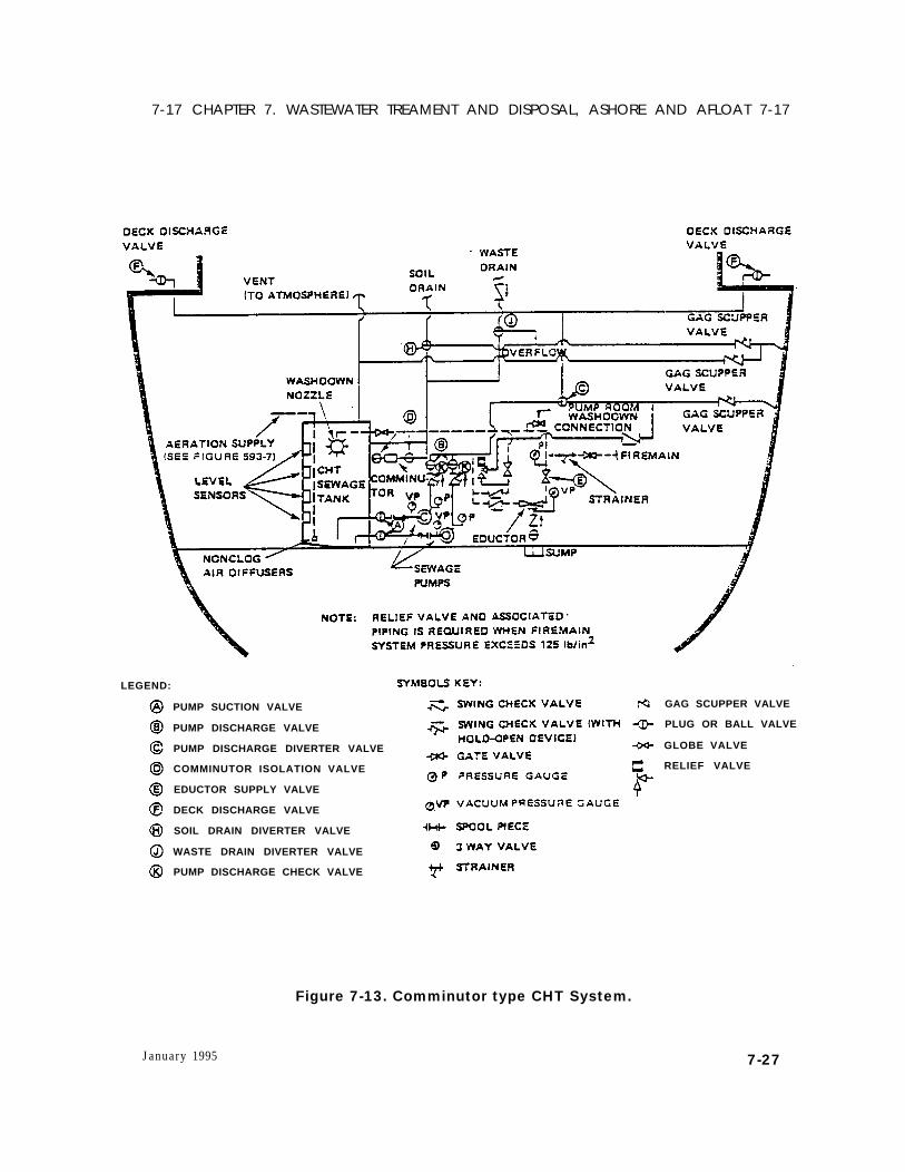
7-17 CHAPTER 7. WASTEWATER TREAMENT AND DISPOSAL, ASHORE AND AFLOAT 7-17
LEGEND:
PUMP SUCTION VALVE
PUMP DISCHARGE VALVE
PUMP DISCHARGE DIVERTER VALVE
COMMINUTOR ISOLATION VALVE
EDUCTOR SUPPLY VALVE
DECK DISCHARGE VALVE
SOIL DRAIN DIVERTER VALVE
WASTE DRAIN DIVERTER VALVE
PUMP DISCHARGE CHECK VALVE
GAG SCUPPER VALVE
PLUG OR BALL VALVE
GLOBE VALVE
RELIEF VALVE
Figure 7-13. Comminutor type CHT System.
January 1995 7-27
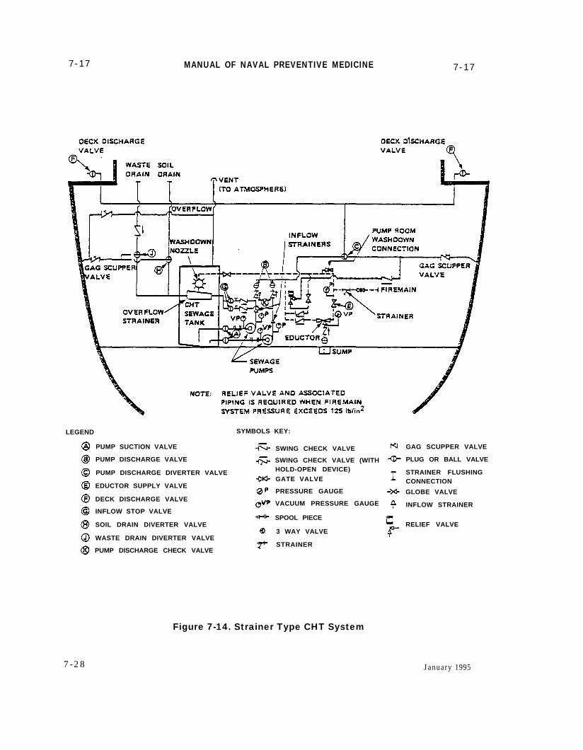
7-17 MANUAL OF NAVAL PREVENTIVE MEDICINE 7-17
LEGEND SYMBOLS KEY:
PUMP SUCTION VALVE
PUMP DISCHARGE VALVE
PUMP DISCHARGE DIVERTER VALVE
EDUCTOR SUPPLY VALVE
DECK DISCHARGE VALVE
INFLOW STOP VALVE
SOIL DRAIN DIVERTER VALVE
WASTE DRAIN DIVERTER VALVE
PUMP DISCHARGE CHECK VALVE
SWING CHECK VALVE
SWING CHECK VALVE (WITHHOLD-OPEN DEVICE)GATE VALVE
PRESSURE GAUGE
VACUUM PRESSURE GAUGE
SPOOL PIECE
3 WAY VALVE
STRAINER
GAG SCUPPER VALVE
PLUG OR BALL VALVE
STRAINER FLUSHINGCONNECTION
GLOBE VALVE
INFLOW STRAINER
RELIEF VALVE
Figure 7-14. Strainer Type CHT System
7-28 January 1995
7-17 CHAPTER 7. WASTEWATER TREAMENT AND DISPOSAL, ASHORE AND AFLOAT 7-17
Figure 7-15. GATX Evaporative Toilet System
e. In unrestricted waters, wastewateris discharged directly overboard. In port,the wastes are incinerated or discharged di-rectly into a shore collection facility o rSWOB.
4. KOEHLER-DAYTON (KD) Recircu-lating Flush System
a. The Koehler-Dayton RecirculatingFlush System is designed for small craft andships whose mission requires extensive op-erations within the restricted zone.
b . T h i s s y s t e m c o n s i s t s o f arecirculating flush toilet with a 20-gallonholding tank (KD unit), an electrical o rmanual recirculating pump, 30-gallon stor-age tank, and a macerator/transfer (M/T)pump for discharging both holding tanks,plus associated plumbing and controls.
c. The KD unit is initially charged with4 gallons of fresh water to which is added 4ounces of chemical-containing deodorizers,coloring and wetting agents, a biocide, and,in the event of freezing temperatures, anti-freeze. Whenever the unit holding tank isdrained into the 30-gallon storage tank ordischarged overboard, the unit must be re-charged with flushing medium.
d. Wastes are carried to the 20-gallonunit holding tank in the recirculating flushmedium. The flushing medium is pumpedfrom the unit holding tank through a filter orbaffle device, where the solids are removed,and back to the toilet bowl for reuse. The 20-gallon unit holding tank is designed to ac-commodate approximately 160 uses before itmust be emptied; however, the manufac-turer recommends the unit be drained into
January 1995 7-29
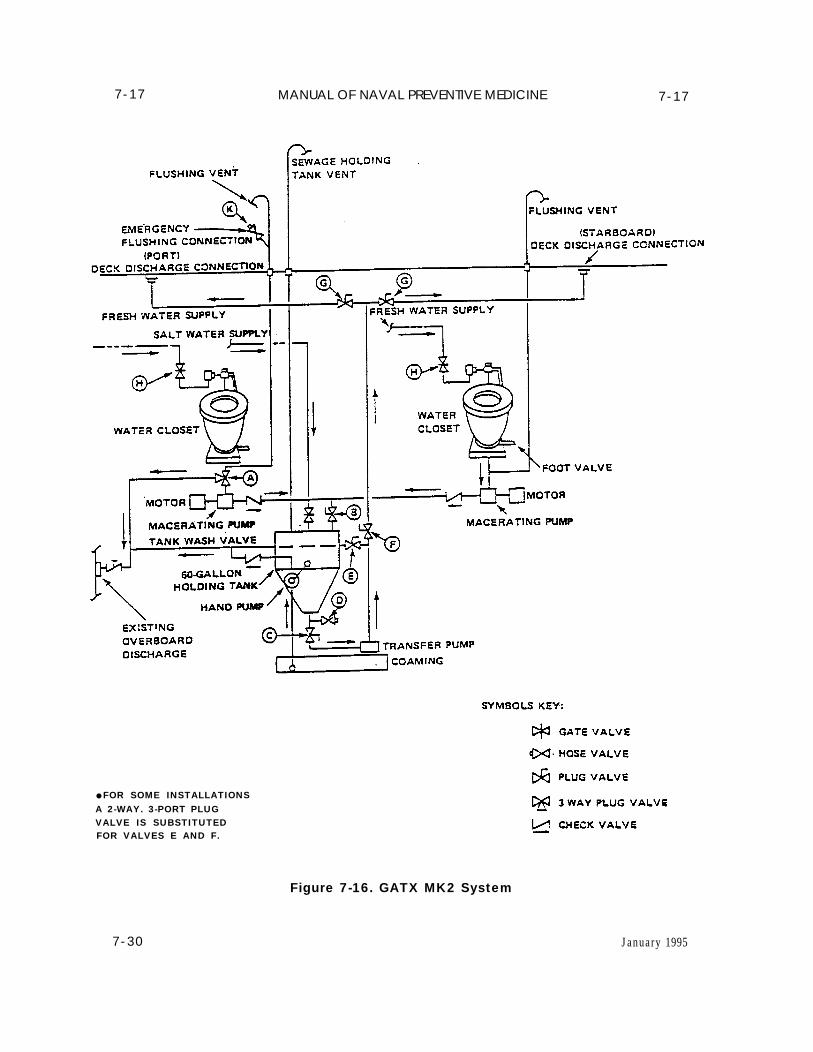
7-17 MANUAL OF NAVAL PREVENTIVE MEDICINE
● FOR SOME INSTALLATIONSA 2-WAY. 3-PORT PLUGVALVE IS SUBSTITUTEDFOR VALVES E AND F.
7-30
7-17
Figure 7-16. GATX MK2 System
January 1995
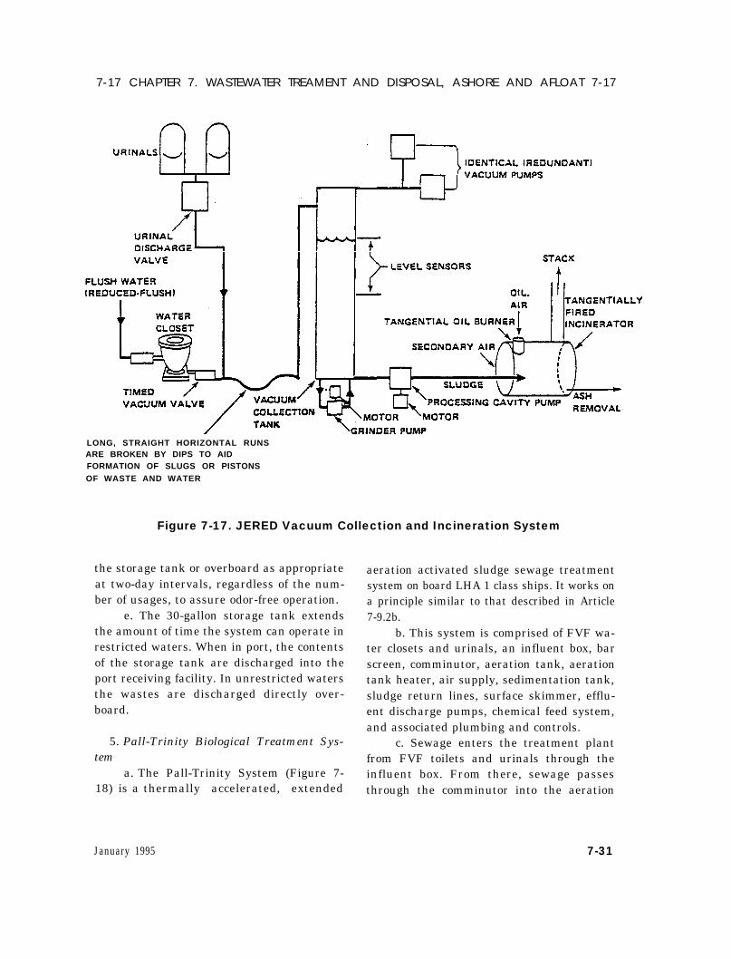
7-17 CHAPTER 7. WASTEWATER TREAMENT AND DISPOSAL, ASHORE AND AFLOAT 7-17
LONG, STRAIGHT HORIZONTAL RUNSARE BROKEN BY DIPS TO AIDFORMATION OF SLUGS OR PISTONSOF WASTE AND WATER
Figure 7-17. JERED Vacuum Collection and Incineration System
the storage tank or overboard as appropriateat two-day intervals, regardless of the num-ber of usages, to assure odor-free operation.
e. The 30-gallon storage tank extendsthe amount of time the system can operate inrestricted waters. When in port, the contentsof the storage tank are discharged into theport receiving facility. In unrestricted watersthe wastes are discharged directly over-board.
5. Pall-Trinity Biological Treatment Sys-tem
a. The Pall-Trinity System (Figure 7-18) is a thermally accelerated, extended
aeration activated sludge sewage treatmentsystem on board LHA 1 class ships. It works ona principle similar to that described in Article7-9.2b.
b. This system is comprised of FVF wa-ter closets and urinals, an influent box, barscreen, comminutor, aeration tank, aerationtank heater, air supply, sedimentation tank,sludge return lines, surface skimmer, efflu-ent discharge pumps, chemical feed system,and associated plumbing and controls.
c. Sewage enters the treatment plantfrom FVF toilets and urinals through theinfluent box. From there, sewage passesthrough the comminutor into the aeration
January 1995 7-31
7-17 MANUAL OF NAVAL PREVENTIVE MEDICINE 7-18
tank. In the event the comminutor becomesclogged, sewage enters the aeration tankthrough the bar screen. Sewage is decom-posed in the aeration tank by aerobic bacte-ria in an environment rich in oxygen andmaintained between 85°F and 105° F by theaeration tank heater. The effluent leavingthe aeration tank enters the sedimentationtank where sludge settles to the bottom andis conveyed back to the aeration tank by thesludge return lines for further treatment.When the sludge accumulation in the sedi-mentation tank reaches 40% of the tank ca-pacity, it is pumped out and dischargedoverboard in unrestricted waters or to ashore receiving facility. The scum, whichforms at the top of the sedimentation tank, isremoved by the surface skimmer and re-turned to the aeration tank. The clarifiedeffluent from the sedimentation tank entersthe effluent holding tank where chlorine isadded to disinfect the treated wastewaterbefore it is discharged overboard.
7-18. Inspection of Marine SanitationDevice:
1. Labeling and Color Codinga. On the interior of the ship, MSD
valve handles and operating levers (exclud-ing handwheels of gauge valves located ongaugeboards) must be color coded gold (PaintChip 17043). Exterior deck discharge sta-tions must be painted the same color as thesurrounding structure.
b. Deck discharge stations must beclearly labeled to include hose handling pro-cedures and sanitary health precautions asdescribed in GENSPECS 593.
2. MSD components must be regularly in-spected for leaks by appropriate engineeringpersonnel responsible for the compartment
in which the MSD components are located.These inspections should include the follow-ing:
a. Soil and waste drains, dischargelines, flanges, joints, access plates, and cleanout plugs.
b. Gate and ball valvesc. Plug valvesd. Comminutors and motorse. Automatic pump startersf. Sewage pumps, including housings
and sealsg. Tank penetrations and manholesh. Air compressorsi. Drip pansj. When operating in “port” mode, in-
clude sewage transfer hoses and riser con-nections
3. The “paper towel” test can be used top inpoint smal l l eaks f rom pumps,comminutors and pressurized sections of thepiping system. This test entails opening apaper towel and holding it suspended 2 to 3inches from the units for several minuteswhile they are operating. The source of eventhe finest spray can be detected by the papertowel becoming spotted or wet.
4. The ventilation system installed in theMSD room must be inspected and the spacesump (if present) must be checked for sewageaccumulation.
5. All leaks, spills or other sources of con-tamination observed during these inspec-tions or at any time must be promptly reportedto the executive officer, engineering officer/damage control officer, and the senior medicaldepartment representative. Appropriate ac-tion must be taken to arrest the leak andproperly clean and, when appropriate, disin-fect the contaminated area as described in Ar-ticle 7-20.
7-32 January 1995
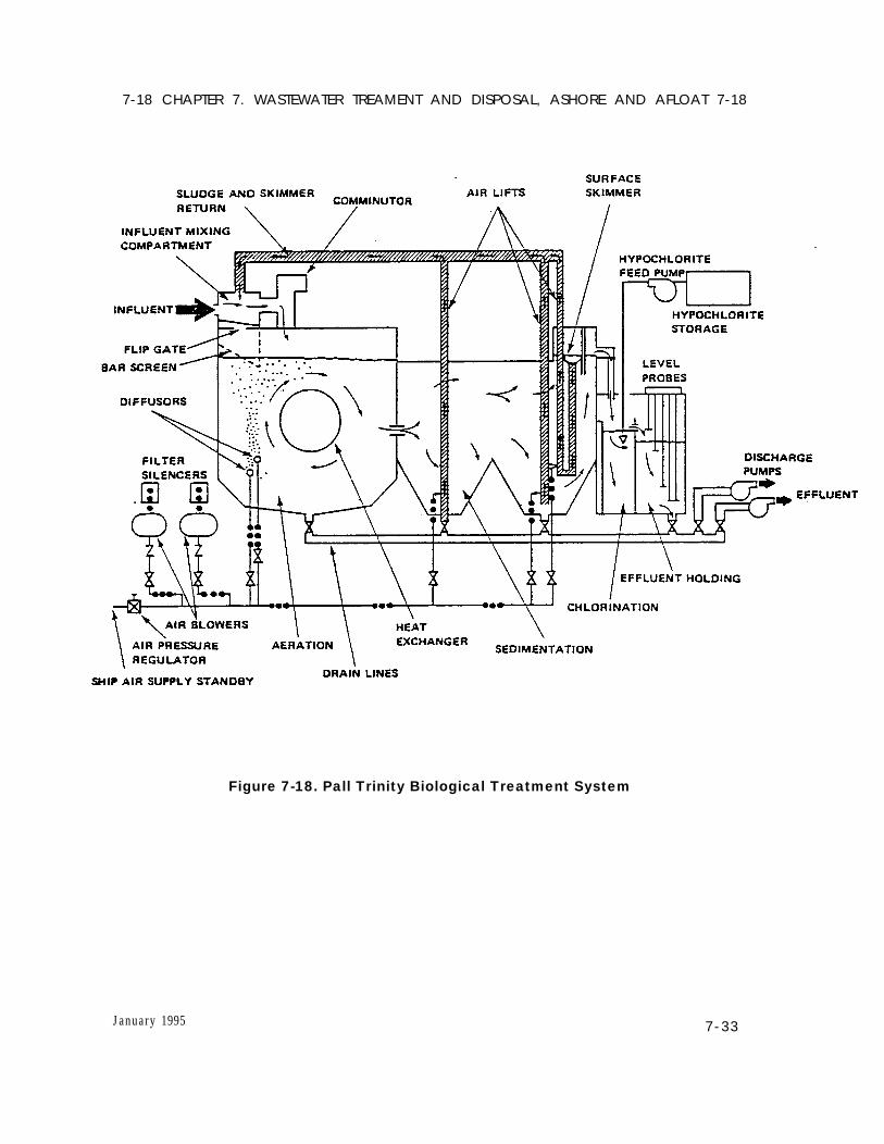
7-18 CHAPTER 7. WASTEWATER TREAMENT AND DISPOSAL, ASHORE AND AFLOAT 7-18
Figure 7-18. Pall Trinity Biological Treatment System
January 1995 7-33
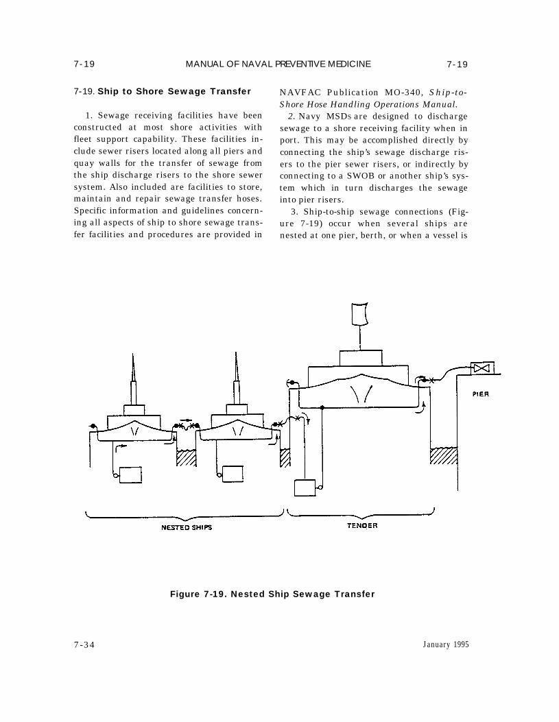
7-19 MANUAL OF NAVAL PREVENTIVE MEDICINE 7-19
7-19. Ship to Shore Sewage Transfer
1. Sewage receiving facilities have beenconstructed at most shore activities withfleet support capability. These facilities in-clude sewer risers located along all piers andquay walls for the transfer of sewage fromthe ship discharge risers to the shore sewersystem. Also included are facilities to store,maintain and repair sewage transfer hoses.Specific information and guidelines concern-ing all aspects of ship to shore sewage trans-fer facilities and procedures are provided in
NAVFAC Publication MO-340, Ship-to-Shore Hose Handling Operations Manual.
2. Navy MSDS are designed to dischargesewage to a shore receiving facility when inport. This may be accomplished directly byconnecting the ship’s sewage discharge ris-ers to the pier sewer risers, or indirectly byconnecting to a SWOB or another ship’s sys-tem which in turn discharges the sewageinto pier risers.
3. Ship-to-ship sewage connections (Fig-ure 7-19) occur when several ships arenested at one pier, berth, or when a vessel is
7-34
Figure 7-19. Nested Ship Sewage Transfer
January 1995
7-19 CHAPTER 7. WASTEWATER TREAMENT AND DISPOSAL, ASHORE AND AFLOAT 7-19
nested to a tender. Ships with CHT systemshave athwartship piping which allows themto receive sewage from an adjacent ship andtransfer it to another ship with the samecapability. Thus, several ships’ CHT systemscan be connected in series such that thesewage generated on these ships, is conveyedthrough the inboard ships’ systems to thepier risers. Vessels with other than CHTsystems do not have the pump-through capa-bility and must be connected directly to apier, SWOB, or a ship such as a tender whichhas pump-through capability.
4. Most sewage connections, includingship-to-shore and ship-to-ship, are made bymeans of 50-foot length, 4-inch flexible rub-ber or plastic sewage transfer hoses whichare provided by the sewage receiving facility.The only exceptions are submarines whichuse a 50-foot length, 2-1/2 inch rubber hose.When a ship arrives for berthing, a shorebased handling crew delivers the properamount of clean sewage transfer hoses to thepier, and connects the hoses to the pier ris-ers. The ship’s crew is responsible for con-necting transfer hoses to the ship’s risers onship-to-shore and ship-to-ship connections.
5. Sewage transfer hoses must be keptclean and in good repair to avoid unsanitaryconditions. Prior to returning the hoses tostorage after use, they must be cleaned ofresidual wastewater. This is usually accom-plished by flushing the hoses for at least 10minutes prior to disconnection with highpressure salt water which is admitted intothe MSD discharge piping from the ship’sfire fighting system. When a vessel does nothave this capability, the shore crew mustflush the hoses by connecting them to thenearest saltwater pier riser. In addition,hose couplings and exterior surfaces must becleaned and the ends of the hoses cappedprior to storage. Sewage transfer hoses must
never be used for potable water connections.6. In the event wastewater is spilled onto
the -deck of the ship or onto the pier, theaffected area must be thoroughly flushedinto the harbor with high pressure salt orfresh water. An approved disinfectant suchas NSN 6840-00-753-4797, disinfectant Ger-micidal Fungicidal concentrate (phenolictype) may be used to prevent or eliminatestrong odors caused by the wastewater spill.
7. Sewage hose handling and storage fa-cilities are designed to accommodate the re-pair, maintenance, and storage of sewagetransfer hoses. Hose handling and storagefacilities are required to incorporate the fol-lowing design features to preclude conditionswhich could cause accidents or communi-cable diseases:
a. Racks and tables used for the han-dling and storage of sewage transfer hosesmust be constructed of metal or other im-pervious material. Wooden racks and tablesare prohibited.
b. All windows and doors which open tothe outside must be adequately screened toprevent the entry of flying insects.
c. Back siphonage prevention devicesmust be installed on all potable water linesused for flushing and cleaning sewage trans-fer hoses.
d. Lavatories and showers with hot andcold running water, soap, and single usetowels must be provided.
e. Sufficient ventilation must be pro-vided in all indoor work spaces.
f. Incandescent and fluorescent lightsmust be protected from breakage, and non-slip surfaces must be installed on the deck inthe hose washing areas.
g. Disinfection of sewage transfer hosesis not normally required; however, the hosehandling facility should have this capabilityin the event the need arises.
January 1995 7-35
7-19 MANUAL OF NAVAL PREVENTIVE MEDICINE 7-20
h. The sewage hose handling and stor-age facility must be constructed, equippedand operated in conformance with appropri-ate health and safety requirements promul-gated by the Occupational Safety and HealthAdministration (OSHA).
7-20. Personal Hygiene, Sanitationand Safety
1. Strict adherence to good personal hy-giene and sanitary practices is essential toprevent the spread of fecal contaminationand resulting potential for the occurrence ofcommunicable diseases.
2. Personnel are required to wear protec-tive clothing including coveralls, rubberboots, rubber gloves, face shields, hair cov-ering and an oxygen breathing apparatus(OBA) as appropriate when contact withsewage is likely during maintenance, or spillclean-up operations.
3. Personnel who come in contact withsewage in the course of their duties, or as theresult of a sewage spill or system backflowmust adhere to the following requirements tominimize the spread of contamination toother areas of the ship.
a. Movement about the ship wearingcontaminated clothing must be kept to anabsolute minimum.
b. Contaminated clothing must beplaced in a plastic bag at the conclusion ofmaintenance or spill clean-up operations forlaundering in hot water and detergent. Nospecial laundering procedures are required.
c. Rubber boots, gloves, OBA, and othersimilar items must be washed with hot soapywater, rinsed with hot clean water andtreated with an approved disinfectant solu-tion.
d. Personnel must thoroughly washwith soap and water before engaging in other
activities. In the event of a sewage spill, allsanitary and safety requirements specifiedin Naval Ships Technical Manual (NSTM)593 must be strictly followed.
4. Spaces which become contaminatedwith sewage as a result of leaks, spills, orsewage system backflow must be thoroughlywashed down with water and a stock deter-gent. In addition, food service spaces,•berthing areas, and medical spaces must betreated with an approved disinfectant (EPAregistered and labeled) such as NSN 6840-00-753-4797, Disinfectant, Germicidal Fun-gicidal Concentrate (Phenolic Type) or NSN6840-00-526-1129, Disinfectant, Germicidaland Fungicidal Concentrate (Iodine Type).To be effective, these agents must be used inaccordance with instructions printed ontheir respective labels.
5. Bilges contaminated with sewagewastes must be pumped out, washed downwith a fire hose and pumped out again. Ifpotable water tanks form the floor of thebilge, daily bacteriological monitoring of thewater from those tanks must be promptlyinitiated and continued until it is assuredthat sewage contamination of the tanks hasnot occurred. Furthermore, if the potablewater system is suspected of being contami-nated, the appropriate tanks must be se-cured until the water is determined to besafe.
6. Signs must be posted in spaces con-taining MSD equipment warning mainte-nance personnel against consuming food andbeverages or smoking in MSD spaces anddirecting them to thoroughly wash with soapand water prior to leaving the area.
7. Personnel who handle or connect sew-age transfer hoses must not subsequentlyhandle potable water hoses without firstwashing, and changing into clean clothing.
7-36 January 1995
7-20 CHAPTER 7. WASTEWATER TREAMENT AND DISPOSAL, ASHORE AND AFLOAT 7-22
8. There must be no open flames, flash-lights, or other electrical apparatus in ornear open holding tanks or other voids untilthey have been certified safe by a gas-freeengineer. When the tank is designated gas-free and safe, personnel may enter using an(OBA) or other approved respiratory protec-tion device specified in NSTM Chapter 593.A safety harness and tending line must beused if only a single person enters the tank.If more than one person enters the tank, theymust keep in constant sight of one another.Personnel must always be on hand outsidethe tank to watch those inside and the readyto lend assistance. See Article 7-22 and 7-23for additional health and safety provisions.
7-21. Medical DepartmentResponsibilities
1. The presence of marine sanitation de-vices and the associated equipment and fa-cilities aboard ship increase the risk ofexposure to untreated wastewater which inturn increases the potential for the occur-rence of infectious diseases associated withhuman waste. Since preventive medicine isan integral part of the medical departmentresponsibility aboard ship, it is incumbentupon the MDRs to become familiar with theMSD system aboard their ship; knowledge-able in the proper personal hygiene practicesand decontamination procedures with re-gard to the operation and maintenance ofMSD systems; and to take an active role toinsure the systems are operated and main-tained in a safe and sanitary manner.
2. The MDR’s duties must include the fol-lowing:
a. Conduct visual inspections of MSDcomponents as described in Article 7-18 aspart of the routine habitability and sanita-tion inspection program or on a more fre-quent basis as the situation dictates.
Whenever practicable, inspections should beconducted in conjunction with engineeringdepartment personnel.
b. Indoctrinate personnel associatedwith the operation, maintenance, and repairof MSD systems concerning the potentialhealth hazards associated with humanwastes, proper personal hygiene necessary toreduce the risks associated with workingwith MSD systems, and the correct proce-dures for cleaning and disinfecting contami-nated spaces. This training must beconducted on a periodic basis to ensure thatthe appropriate personnel are able to operateand repair the MSD system without endan-gering themselves or the ship’s crew.
c. Provide on-site advice, when re-quested, in the correct procedures for per-sonal protection and disinfection of spaces inthe event of major sewage leaks or spills. TheMDR must be present for clean-ups and dis-infection of food services spaces, living areas,and medical spaces.
7-22. Safety and Health Hazards ofCHT Systems
1. A serious potential hazard associatedwith CHT systems is that toxic or explosivegases could be released in confined spaces.Hydrogen sulfide has been identified as themost likely gas hazard associated with thedecomposition of sewage in CHT tanks,however, other gases may include methane,ammonia, and carbon dioxide.
2. The following precautions will mini-mize the potential hazards resulting fromthe release of toxic gases.
a. Insure that the installed CHT tankaeration system is operated properly intanks larger than 2,000 gallons. The aera-tion system must be operated while transit-ing the three-mile zone or while in port assanitary wastes are being collected. Systems
January 1995 7-37
7-22 MANUAL OF NAVAL PREVENTIVE MEDICINE 7-23
with tank capacities of less than 2,000 gal-lons do not have aeration systems; but be-cause of the smaller tank capacity, the CHTdischarge pumps will cycle more often whilein port.
b. Always assume the CHT tank con-tains sewage and toxic gases. Any mainte-nance requiring the removal or disassemblyof valves, pumps, flanges, etc. inside theCHT pump room or below the CHT overflowmust be conducted in accordance with theNaval Ships’ Technical Manual, NAVSEAS9086-T8-STM-010, Chapter 593, Para-graph 4.21.2.1 through 4.21.2.10.
c. Personnel working in the CHT pumproom, comminutor space, or any space con-taining CHT piping, must evacuate the spaceimmediately if hydrogen sulfide is detectedby a “rotten egg” smell or by a portable per-sonal hydrogen sulfide alarm. A space inwhich hydrogen sulfide has been detectedmay only be reentered by personnel wearingair line respirators with full face masks.
d. Corrective maintenance not requir-ing immediate attention should be deferreduntil the ship is port and industrial facilitiesare available. In a situation where holdingwastes presents a health or safety hazard,the system should be secured and an engi-neering casualty report filed. If retention ofwaste interferes with operational effective-ness, it may be diverted over the side.
e. Smoking, eating, or drinking is neverpermitted inside CHT pump rooms,comminutor spaces or when working on anyCHT component.
7-23. CHT Pump Room Safely1. In most cases, CHT pumps are located
in very small compartments on lower decklevels. This provides an excellent collectionbasin for heavier-than-air gases, such as hy-drogen sulfide.
2. To eliminate hazardous gas exposuresin CHT pump rooms, it is strongly recom-mended that:
a. Slightly negative pressure ventila-tion, to include powered air supply and ex-haust ventilation be installed in CHT pumprooms in accordance with General Specifica-tions for Ships of the United States Navy(GENSPECS), Section 512. The exhaustventilation ducting should extend to within 9inches of the deck.
b. An indicator light be installed out-side the compartment to indicate the venti-lation system is operating.
c. Two emergency escape breathing de-vices (EEBD) be placed in each CHT pumproom.
d. A portable hydrogen sulfide detectorbe used during all CHT maintenance.
e. A placard be installed at access to theCHT pump room stating the following:
SEWAGE SPILLS PRODUCEHAZARDOUS GASES
1. SEWAGE SPILLS CAN PRODUCEHAZARDOUS GASSES
2. USE EEBD MOUNTED IN PUMPROOM FOR EMERGENCY ESCAPE INEVENT OF SEWAGE SPILL
3. FOLLOW SAFETY PROCEDURES INNAVSHIPS TECHNICAL MANUAL,“POLLUTION CONTROL,” N A V S E AS9086-T8-STM-010/CH-593 DURING SYS-TEM MAINTENANCE OR SPILL CLEANUP
4. USE OBA ONLY FOR EMERGENCYRESCUE AND DAMAGE CONTROL (SE-CURING OF FLOODING)
7-38 January 1995
7-23 CHAPTER 7. WASTEWATER TREAMENT AND DISPOSAL, ASHORE AND AFLOAT 7-23
f. The following label plate be placed inthe vicinity of each CHT holding tank accessand sewage tank access:
TOXIC OR EXPLOSIVE GASES MAYEXIST IN THE TANK. DO NOT OPEN UN-LESS AT A SUITABLE INDUSTRIAL AC-TIVITY AND TANK HAS BEEN CERTIFIEDGAS FREE IN ACCORDANCE WITH THE
REQUIREMENTS OF NAVAL SHIPSTECHNICAL MANUAL, ENTITLED “POL-LUTION CONTROL,” PUBLICATIONNAVSEA S98086-T8-STM-010/CH-593.
g. A safety watch with a spare OBAmust be posted at the compartment accessany time maintenance is conducted whichrequires the system to be opened in thepump room, or in any space below the CHTtank overflow.
January 1995 7-39