manual pacific 250 inglese - västerorts dyk nardi/manual pacific 250 inglese.pub.pdf · 1...
TRANSCRIPT

1
Instruction Manual and Spare Parts Catalogue Pacific 250
This manual contains operating instructions and maintenance schedules for the high pressure breathing air compressors. Operators must read and understand all information inside the manual. ATTENTION. This machine can be used only after a careful reading of this instruction manual. The machine may only used to produce compressed air. Other use is strictly prohibited. The manufacturer and the supplier void all responsibility for damage or injury resulting from failure to follow these instructions.
ENGLISH INSTRUCTION MANUAL

2
INSTRUCTION MANUAL PACIFIC 250
1. GENERAL INFORMATION: Before using the machine please put your attention to this general information: 1. Personnel engaged to operate the machine must have read the instruction manual before beginning work, especially the safety notices chapter. 2. Personnel may not wear long hair loose, loose clothing or jewellery, including rings. 3. Keep all safety and danger notices on the unit complete and in readable condition. 4. No modifications may be made to the unit which could impair safety without first obtaining permission from the suppliers. 5. Piping must be thoroughly checked (pressure and visual inspection) by the operator at appropriate time intervals, even if no safety related faults have been noticed.. 6. Intervals stipulated or given in the insruction manual for recurring checks/inspections must be adhered to. 7. It is absolutely essential that the workplace is appropriately equipped for maintenance measures. 8. Work on/with the unit may only be carried out by reliable personnel. Observe the legal minimum age permissible. 9. Only employ trained personnel, clearly establish responsibility of personnel for operation, maintenance and repair-work. 10. Ensure that only trained personnel work with the machine.
2. PURPOSE AND SHORT DESCRIPTION: The PACIFIC P 250 high pressure compressors are designed to compress air for braeathing as required in diving and fire fighting applications. The max pressure is 225 bar or 330 bar depending on unit. The compressor unit comprises the following major assemblies:
• Compressor block
• Electric or petrol/diesel engine
• Filters
• Filling assembly
• Protection and anti-vibration frame
• Automatic condensate drain*
• Electric control system**
• Automatic switch on/off*
• Inox frame*
(*) Optional extra according to order

3
3. COMPRESSOR BLOCK The compressor block PACIFIC 250 is used to compress air in the high pressure range up to 420 bar (6000 psi). The compressor block is of a three stage, three cylinders design. The cylinders are arranged in a W form, the 1st stage in the centre, 2nd stage on the right, and 3th stage on the left side looking from the filter side. The compressor bloks are particularly suitable for continuous operation because of their rugged design and the corrosion resistant intermediate filter and cooler assemblies. Smooth running is a particolar feature of this Nardi design. The moving parts of the driving gear are all equally balanced. This results in a vibration-free running. The driving gear is fitted with energy saving cylinder roller bearings. The upper and lower connecting rod bearings are also roller bearings. Crankcase, cylinders and heads are obtained from the gravity dies. Connecting rod are extracted from casting dies. Cylinder are in cast iron inside an aluminium pipe. Temperature can not reach high level thanks to this specific material used: the best solution against heating and corrosion. The oil geared pump with filter linked together with the classic flapping system assure a lubrification also in the worst conditions. This allows for an even longer life of the machine.
Description 1. Intake filter 1st stage 2. Valve Head 1st stage 4. Inter-cooler 1st stage 6. Inter-cooler 2nd stage 7. Head 2rd stage and safety valve 1nd stage 9. Intermediate separator 2nd stage 10.Safety valve 2nd stage 11.Head 3th stage 12.Separator 3th 13.Safety Valve 225 or 330 Bar ( 3200 or 4700 Psi ) 14.Oil drain 15.Oil pump 16.Oil filter housing
INSTRUCTION MANUAL PACIFIC 250

4
4. TECHNICAL DATA
Compressor unit PACIFIC 250 electric
Operating pressure PN 200 PN 300
Delivery * 250 l/min. 250 l/min.
Final pressure safety valve 225 bar 330 bar
Compressor block PACIFIC 250
Number of stages 3
Number of piston 3
Cylinder bore stage 1 88 mm
Cylinder bore stage 2 28 mm
Cylinder bore stage 3 12 mm
Piston stroke 40 mm
Intermediate pressure stage 1 12 bar
Intermediate pressure stage 2 55 – 75 bar
Intermediate pressure stage 3 225 - 330 bar
Oil capacity 3,5 litri
Oil pressure MAX 0,5 bar
Oil type Nardi oil High pressure
Max permissibile ambient temp. Olio normal Nardi Compressori -5° a +45°C ( +28° a +113°F ) - Olio technical 1 Nardi Compressori –25° a +35°C ( -9° a +95°F )
Max permissibile inclination of compressor 20°
Max dampness 80 %
Max sea level 2000 m sea level
Weight 55 Kg.
Drive engine Three phase
Operating voltage 380 - 415 Volt 50 Hz ; 380 - 480 Volt 50 Hz
Power 5,5 kW - 7,5 Hp
Speed 2890 r.p.m.
Mec 132
Type of enclosure IP 54
Current rating 13 Amps
Petrol engine HONDA (Gasoline) GX270 K1
Switch on/off Automatico (Optional)
Cubic capacity 270 cmq
Power 9 cv - 6,6 kW a 3600 r.p.m.
Consumption/h (unleaded petrol) 3 lit. (Tank capacity 6,0 Litres)
INSTRUCTION MANUAL PACIFIC 250

5
5. SAFETY MEASURES 5.1. Fundamental safety notices: Important instructions concerning the endangerment of personnel, technical safety and operating safety will be specially emphasized by special marks placing on the machine. For safety reasons you can find some components mounted on the compressors in order to prevent damages. These parts must not be changed or removed in any case. Before please consult our technician.
5.2. Authorized use : The unit is built according to state of the art technology and established safety technical regulations. Neverthless, its use can cause danger to life and limb of the operator or third parties or damage to the machine and other equipment. Operate the unit only in technically perfect condition in accordance with regulations and safety danger notices detailed in the instruction manual. The manufacturer/supplier is not re-sponsible for damage resulting from a wrong utilisation of the machine. The user alone is responsible for this risk. The compressor is built to produce top quality breathing air according to DIN EN 12021 rules.
5.3. Safety notices for operation : • Ensure that only trained personnel work with the machine.
• Filling hoses must be in satisfactory condition and threads undamaged..
• Ensure intake air is free from noxious gas,exhaust fumes and solvent vapour.
• The use of petrol and diesel compressors is forbidden in indoor place.
• Check the unit externally for damage and faults periodically. Inform the department/person responsible immediately if anything is not as is should be (including opearation). If necessary, shut the machine down immediately and make it safe.
• Observe switching on and off processes and monitoring indications according to the instructions manual.
• Use only Nardi original parts and equipments.
• Drain the valve regularly if manual drain valve. Check every ten minutes the valve if automatic drain valve.
• Switch off the machine when do not use it.
• Clean oil, fuel or care products from, the machine, in particular the connections and screw joints, before carrying out maintenance/repairwork. Do not use aggressive cleaning fluid. Use a fibre-free cleaning cloth.
• Completely remove all covers/seals after cleaning.
• Use only original fuses with specified current rating. If there is a failure in the electric energy supply, shut the machine/unit down immediately.
• Work on elelectric units or operating equipment may only carried out by a qualified electrician or by a person under the instruction and supervision of qualified electrician according to electric technical regulations.
• The electrical equipment of a unit must be regularly checked.
• When working in small rooms, observe any national regulations.
• Depressurize system and pressure lines before commencing repairwork.
• With regard to oil, grease and other chemical substances, ovserve the relevant safety rules for the product.
• When switching on the machine, check the arrow to ensure correct direction of rotation of the drive motor.
INSTRUCTION MANUAL PACIFIC 250

6
6. WARRANTY 6.1. Compressor warranty : Our compressors are warranted for 12 months from the delivery of the goods starting from the date showed in the documents. Warranty is valid only if the buyer respects all contract rules and the compressor is used according to our indications. Warranty is excluded for:
• Bad use
• The spares necessaries for a periodically maintenance.
• The use of not original spares.
• Other gas different to air or with more of 21% oxygen. Reparation must be made inside Nardi factory and the compressors must always delivered at the buyer’s charges and risks. Otherwise, in case of outside reparation all transport costs will be debted to the buyer (only trained personnel can work with the machine). If the reparation needs of a Nardi technician, all trip charges must be debted to the buyer.
7. INSTALLATION, OPERATION, FILLING PROCEDURE 7.1. Installation of the compressor unit: The compressor frame is equipped with anti-vibration mounts. The compressor is not seawater resistant . At operation in salty air spray com-pressor with anticorrosive protection. Electric driven units should be operated and stored below deck. Units with petrol engine should also be stored below deck after the filling process. Take care with the electrical unit.
7.2. Outdoor location: For installation observe the following:
• Locate the unit level in a good and safety place.
• Only clean air must be used. For petrol engine is important to position compressor in direction of wind so that exhaust fumes are blown away from the unit. It is good practice to have an intake hose with pre-filter and intake filter. Pre filter to be located high above ground. This arrangement will ensure necessary spacing between exhaust outlet and air inlet. On petrol or diesel engine, operation unit must only be located outdoors, never indoors.
• Do not operate unit in the vicinity of open fire(flue gas). 7.3. Indoor location: Ensure adeguate ventilation. Air must be free from exhaust fumes and hazard-ous vapours (smoke, gas, solvent vapours and so on.) Do not smoke inside the operation room. If possibile install unit such a manner that the compressor fan can get fresh air from outside. Open the wall if necessary. Never operate petrol driver units indoor!
INSTRUCTION MANUAL PACIFIC 250

7
7.4. Electrical installation: For installation of electrical equipment observe the following:
• In the annex of this instruction manual you will find the standard schematic diagrams valid for the respective compressor unit.
• Observe regulations of local electricity supply company.
• Connection must be carried out by an expert only.
• Ensure correct installation of protective conductor.
• Check conformity of motor and control device tension and frequency with those of electric network.
• ATTENTION: check the correct direction of the fan.
8. STARTING OPERATION: 8.1 Preparation for operation WARNING: this machine is built to produce breathing air. It is not suitable for compression of oxygen. Explosion occurs if an oil lubricated compressor is operated with pure oxygen or gases with oxygen content of more than 21%! All compressor units are tested prior to delivery to the customer, so after correct installation of the unit there should be no problem putting it into operation, observing the following points:
• Prior to first operation read Instruction Manual carefully. Make sure that all persons handling the compressor and the filling station are familiar with the function of all controls and monitors.
• Before taking unit into operation after a standstill period of 2 years or more change compressor oil and intake filter.
• Immediately after switching on the system for the first time check the direction of rotation of the motor for compliance with the arrow on the unit. If motor turns in the wrong direction, the phases are not connec-ted properly. Shut down unit immediately and interchange two of the three phase leads in the switch box. Never change leads at the motor terminal board.
• Prior to each operation check the oil level. Only for petrol unit: - check engine oil level according to manufacturer’s instruction manual - check fuel tank. Top up if necessary - open fuel shut-off valve.
• Every time the unit is started up check all systems for proper opera-tion. If any malfunction is observed stop unit immediately and find the cause of the fault or call the service department.
8.2. Starting the unit: Unit with electric engine without compressor control system: The motor is switched on manually by pressing the start button. Machine does not be left alone during working. Check continuosly the right function. On units without automatic condensate drain, the manual condensate drain valves have to be opened before starting the unit, as soon as the unit is running the valves can be closed again. Every 8/10 min drain the valves.
INSTRUCTION MANUAL PACIFIC 250

8
Units with electric engine with automatic control system: This model is deliverd with an automatic control system. Before starting check point 6.1 and then press ON button.Switch off the machine pressing STOP button. Units with petrol engine: Open condensate drain valves on the filters to release pressure, so that motor start without load. Set choke to position START. Start engine with recoil starter or crank handle. As soon as motor runs smoothly return choke to normal operating position. For all units: Close condensate drain valves tightly and run unit to final pressure. Check final pressure safety valve and pressure gauge. As soon as final pressure is reached and final pressure safety valve blows off, open condensate drain valves and drain condensate - unit is ready for filling operation.
9. FILLING PROCEDURE: 9.1. Connecting the bottles: WARNING: Filling hoses must be in satisfactory condition and threads undamaged.Pay particolar attention to damage on the interface from hose fitting to hose. If the rubber is scored, hose must be discarded otherwise water can enter and attack wire gauze causing it to rust. Normally connectors are allowed for pressures up to 200bar (2.850psi). Please follow the process below:
• Connect air bottle to filling valve.
• Open filling valve.
• Open bottle valve—bottle will be filled. .
• Switch on the compressor.
• Upon reaching final bottle pressure close bottle valve first, then filling valve by returning handle to closed position.
• Remove compressed air bottle.
• Depressurize unit before opening valve—A to avoid damage to the change - over device. If it is necessary more pressure of 220bar please ask for the suitable material: safety valves and connectors are different.
10. MAINTENANCE : 10.1. Maintenance record: We recommend that all maintenance work is recorded in a service book, showing the date and details of the work carried out. This will help to avoid expensive repairwork caused by missed maintenance work. Please fill in the appropriate lines to show what maintenance work has been carried out, and sign and date. Remember: 1– always shut down and decompress the complete system prior to car-rying out any work on the compressor; 2– never repair pressure lines by soldering or welding; 3– only use original spares for maintenance or repair work.
INSTRUCTION MANUAL PACIFIC 250
9
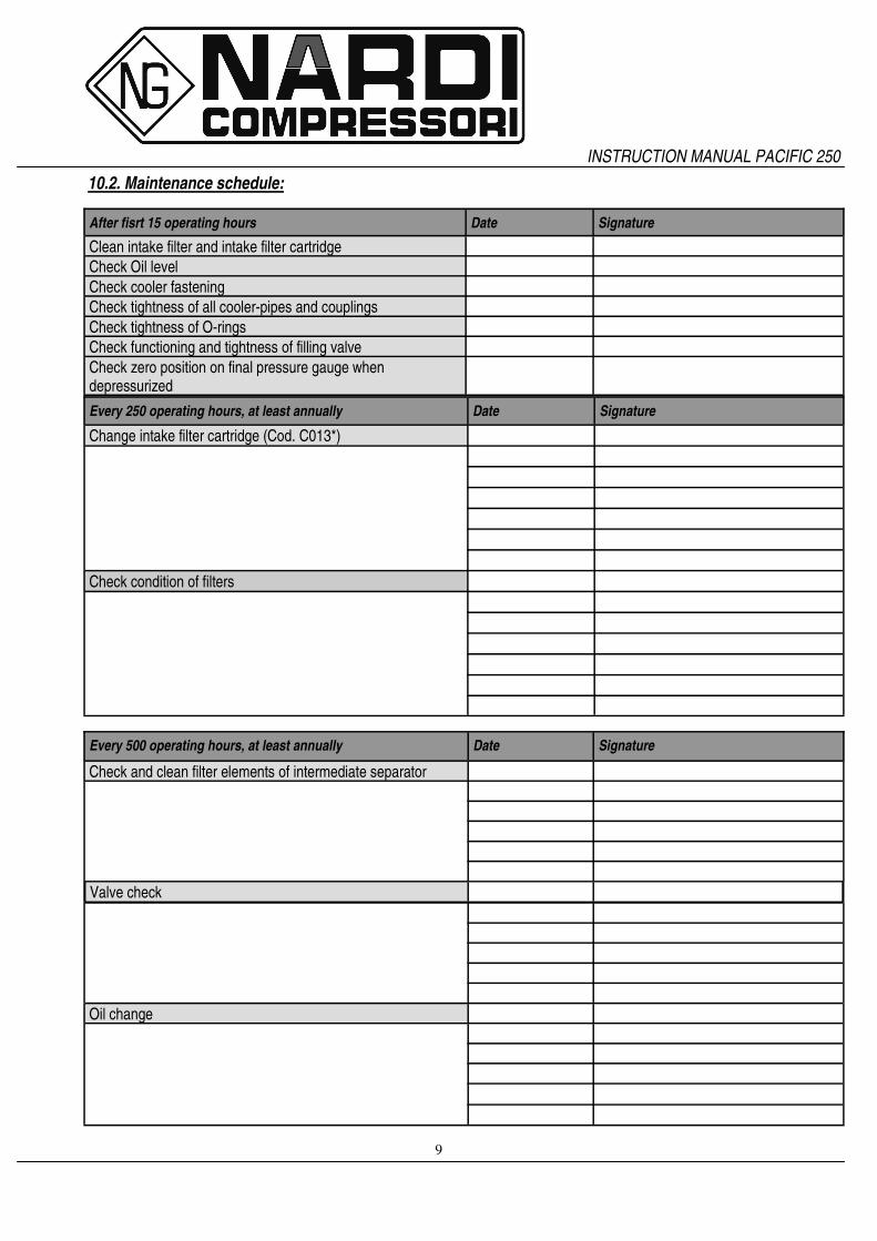
10.2. Maintenance schedule:
After fisrt 15 operating hours Date Signature
Clean intake filter and intake filter cartridge
Check Oil level
Check cooler fastening
Check tightness of all cooler-pipes and couplings
Check tightness of O-rings
Check functioning and tightness of filling valve
Check zero position on final pressure gauge when depressurized
Every 250 operating hours, at least annually Date Signature
Change intake filter cartridge (Cod. C013*)
Check condition of filters
Every 500 operating hours, at least annually Date Signature
Check and clean filter elements of intermediate separator
Valve check
Oil change
INSTRUCTION MANUAL PACIFIC 250

10
Every 1000 operating hours (Nardi technician) Date Signature
Valve change
Annually or as required Date Signature
Perform a breathing air quality check with aerotests
Check blow-off pressure of final pressure safety valve
After repair work Date Signature
Check functioning and tightness of filling valve
Clean intake filter and intake filter cartridge
Check tightness of O-rings
After storage and preservation Date Signature
Check tightness of all cooler-pipes and couplings
Clean intake filter
Check zero position on final pressure gauge when depressurized
INSTRUCTION MANUAL PACIFIC 250

11
11. MAINTENANCE WORK This chapter contains the maintenance work as well as short functional description for each component.
11.1. Lubrication : Two lubrication systems:
• Splashed lubrication: Mechanic lubrication by connecting-rod movement. Connecting-rod has a metal piece below that splashing in the oil during the fast movement causes a spray inside the cylinder.
• Forced lubrication: The oil pump is coupled to and driven by the crank-shaft. It pumps oil from the oil pump through the oil fine filter and a minimum pressure valve to the 3rd stage cylinder. The oil is then distributed by the guide piston of the 3rd stage and lubricates all moving parts of the compressor block.
Forced Lubrication
11.2. Type of oil : Using the correct oil is of vital importance for life and maintenance of the compressor. Nardi has a particular oil studied and tested for the best operation of his machine.Depending on the application of the compressor the requirements placed on the oil are:
• low deposits
• No carbonizing effect, especially in the valves
• Good anti-corrosive properties
• For breathing air application, also physiological and toxicological suitability. Due to the thermal load on the compressor only high quality oil should be used. You are recommended to restrict oils to those which have been approved by us: oil for not mixed air (21% O²).
11.3. Oil change : Please follow the procedure as below:
• Ensure to have a sufficient quantity of oil.
• Run compressor warm.
• Remove red cap from oil filler neck and drain oil while still warm by means of oil drain plug.
• Remove oil filter.
• Mount a new filter element.
• Fill new oil though filler neck to Max.—mark at sight gauge.
INSTRUCTION MANUAL PACIFIC 250

12
11.4. Changing the oil type: To avoid severe damage to the compressor unit when changing the oil type, the following measures should be strictly adhered to:
• Follow the procedure Chapter 9.3.
• Change or clean all parts with old oil.
• After approx. 10 operating hours check lubricating oil for degree of contamination, and change oil again if necessary.
• Fill compressor with the new oil and do not mix different oils.
• Refill compressor with same oil, only.
11.5. Filter oil change (only for compressor with oil pump) : Please follow the procedure as below:
• Remove nut.
• Screw off and take the filter.
• Check the O-ring.
• Assembly the filter and switch on the compressor. Please ensure that oil loss does not happen.
11.6. Intake filter A dry micronic filter is used to filter intake air. The filter cartridge must be cleanded or changed at regular intervals according to maintenance schedule. Do not use any cleaning fluids which are a hazard to respiration. Please clean intake filter as following:
• Remove micronic filter cartridge.
• Clean with brush or by blowing air inside out.
• Change with a new filter and make sure that top cover is installed properly.
11.7. Intermediate separator Separators are designed to remove water and oil accumulation due to cooling the air down after the compression process. An intermediate separator is mounted on the compressor between stages. Inside separators there are some parts that it is necessary to change perio-dically. Remove and clean sintered filter element as follows:
• Switch off the compressor and depressurize separators.
• Remove piping connected to filter head. Screw off union nut. Remove filter head along with sintered filter element.
• Remove centre screw and separate filter element.
• Clean filter element using hot soapy water and blow dry with compressed air.
• Replace O-ring.
• Close the filter strongly. Intermediate separators must be changed after 10.000 operating hours with more then 300 bar of use.
INSTRUCTION MANUAL PACIFIC 250

13
11.8. Coal filter cartridge : Coal filter cartridge removes water condensation and oil by a chemical system not mechanical. Activated carbon and molecular sieve absorb water and oil purifing breathing air according to DIN EN12021. Filter has two safety systems. The first one has a hole closed when the cartridge has put inside. It is not possibile to refill cylinders without cartridge. The second one is designed to prevent pressurizing in the absence of the filter cartridge. A bore provided in the filter bottom is sealed air-tight only if the cartridge is in place. Without cartridge the venting bore is not sealed, the air escapes into the atmosphere and no pressure can be built up. The filter system is subject to dynamic load. It is designed for a certain number of load cycles, which originate from an abrupt pressure loss at condensate drain.After 500 operating hours an inspections have to be arranged by the operator. After reaching the max. number of load cycles: 8000 cycles at 300Bar or 21000cycles at 225Bar the filter as-sembly must be replaced. Approximately, with 4cycles per hour at 300 bar filter must be changed after 2000 operating hours instead at 225 Bar after 5000 operating hours..
11.9. Filter maintenance : The cartridge in the picture removes water and oil Please follow the procedure below:
• Depressurize system before starting any maintenance work.
• Dry inside of filter housing with a clean cloth before installing new cartridge and check for corrosion. Chan-ge if necessary.
• Check the O-ring and change it if damaged.
• Change cartridge before reactiving a compressor unit. The number of operating hours or the amount of possibile bottle fillings per filter cartridge can be determinated taking into consideration the ambient temperature and the cartridge used. To avoid any ranger to your health or damage to your unit, change used up cartridges in good time.Never fill used up cartridges yourself. The filter material was chosen specifically by Nardi compressori for each kind of application. Never remove replace-ment cartridge from packaging prior to actual use otherwise highly sensitive molecular sieve will absorb water vapour from surrounding air and cartridge saturated.
INSTRUCTION MANUAL PACIFIC 250

14
11.10. Lifetime of filter cartridge
Lifetime of filter cartridge Pacific 250 (300 bar)
64
48
37
28
23
18
13
51
39
30
24
1915
11
10 15 20 25 30 35 40
Temperature °C
Ho
urs
Little Damp Higt Damp
Lifetime of filter cartridge Pacific 250 (200 bar)
45
34
26
2016
129
36
28
2117
1310
8
10 15 20 25 30 35 40
Temperature °C
Ho
urs
Little Damp High Damp
INSTRUCTION MANUAL PACIFIC 250

15
11.11. Valves: The valve heads of the individual stages form the top part of the cylinders. The intake and pressure valves are fitted inside the valve heads. Note that the valves are operated by the flow of the medium. On the suction stroke, the intake valves open and the medium flows into the cylinders. At the start of the compres-sion stroke the intake valve closes and the medium opens the pressure valve. Please follow the instructions below for changing the valves:
• Always replace valves as a complete set.
• Carefully clean dirty valves.
• Observe the correct sequence when fitting together again.
• Check individual components for excessive wear. If the valve seat and valve disks are dented, replace the valves.
• Use only satisfactory gaskets and O-rings on reassembly.
• After finishing all maintenance work on the valves, turn the compressor manually and check whether all items have been correctly installed. After 30 minutes after starting, switch off the unit and check again.
• Replace the valves every 1000 operating hours to avoid fatigue failure.
11.12. Valve change: Changing the valves of the 1st stage: Put the attention at the picure and check that the mark ‘T’ Is really at the top. Remove gaskets and O-rings if damaged.
INSTRUCTION MANUAL PACIFIC 250

16
Changing the valves of the 2rd stage: Please follow the procedure below:
• Uscrew the intake and pressure linesfrom the cylinder head.
• Fix the head.
• Unscrew the intake valve body with the special tool. In order to avoid damaging the special tool or the valve when using the tool, ensure that it is pushed properly and firmly into the valve bore so that it will not tilt when it is turner.
• Clean intake and pressure valves and check for wear. Valve seats and plate valves must not show any signs of wear or damage. Replace damaged parts.
• Assembly is performed in the riverse sequence of removal.
• Peen the cylinder head on the screw-in thread of the intake valve in three place with a small drift pin.
• Check the pressure valve function and stoke by lifting the valve plate.
• Check O-rings and replace them if damaged.
• Fix the head at cylinder.
• Reconnect the intake and pressure lines. Changing the valves of the 3th stage: Please follow the procedure below:
• Uscrew the intake and pressure linesfrom the cylinder head..
• Fix the head
• Unscrew the intake valve body with the special tool. In order to avoid damaging the special tool or the valve when using the tool, ensure that it is pushed properly and firmly into the valve bore so that it will not tilt when it is turned.
• Clean intake and pressure valves and check for wear. Valve seats and plate valves must not show any signs of wear or damage. Replace damaged parts.
• Assembly is performed in the reverse sequence of removal.
• Peen the cylinder head on the screw-in thread of the intake valve in three place with a small drift pin.
• Check the pressure valve function and stoke by lifting the valve plate.
• Check O-rings and replace them if damaged.
• Fix the head at cylinder.
• Reconnect the intake and pressure lines.
INSTRUCTION MANUAL PACIFIC 250

17
Pacific 250 SPARE PARTS
Code Description
P A001 Front safety O- ring
P A002 Roller bearing for front shaft
P R003 Compressor shaft pacific 250
P A004 Roller bearing for connecting rod
P A005 Small roller bearing for connecting rod
P A006 Connecting rod without oil thrower pin
P R006 Connecting rod with oil thrower pin
P A007 Washer for bearing connecting rod
P A008 Elastic washer for counterbalance fixing
P R009 Counterbalance
P A010 Rectified screw counterbalance fixing
P A011 Metallic self locking nut for counterbalance fixing
Code
P A012
P A013
Description
Back part safety O- ring
Roller bearing for the back part of the shaft

18
Code Description Code Description
P B001 Compressor crankcase
P B002 Pin flange
P B003 Circlip ring
P B004 Complete connecting rod assembly 250
P B005 Circlip ring
P B006 O-ring closing compressor crankcase
P B007 Closing crankcase flange
P B008 Closing crankcase screw
P B009 Oil seal
P B010 Fixing Flange oil seal
P B011 Screw flange oil seal
P B012 Iron protection
P B013 Screw wire netting
P B014 Pulley compressor
P B015 Washer pulley compressor
P B016 Nut pulley compressor
Pacific 250 SPARE PARTS

19
Code Description Code Description
P D001 Support stirrup tubes high pressure and crankcase P D020 Rilsan tube escape oil 12 mm
P D002 Support stirrup tubes cooling lateral external P D021 Plug
P D003 Support stirrup tubes cooling lateral internal P D022 Visual level plug oil
P D004 Central screw stirrup support lateral tubes P D023 Magneto plug
P D005 Lateral screw stirrup support lateral tubes P D024 Exhaust tap oil
P D006 Nut for stirrup support lateral tubes P D025 Tube suction oil's gear pump
P D007 Fixing nut cooling tubes P D026 Fixing screw oil pump
P D008 Fixing sheet cooling tubes high pressure P D027 Oil's gear pump
P D009 2 throats stirrup support cooling tubes high pressure P D028 O-ring pump crankcase
P E009 "L" 1/4 "connection tube diam. 6 mm P D029 Copper washer 1/4"
P D010 3 throats stirrup support cooling tubes high pressure P D030 O-ring oil filter chamber
P D011 Fixing screw cooling tubes high pressure P D031 Filter holder chamber
P D012 Stirrup nut and crankcase P D032 Oil filter
P D013 Stirrup washer and crankcase P D033 O-ring cover chamber oil filter
P D014 Stirrup screw and crankcase P D034 Cloosing flange oil filter chamber
P D015 Extension oil escape P D035 Screw flange oil filter chamber
P D016 Washer gasket oil escape P D036 No return oil valve
P D017 Labyrinthic extension oil escape P D037 Up-right connection 1/4" tube 6 mm for oil pump
P D018 Load plug oil P D038 Drive-tube oil gear pump
P D019 Fast positive clutch 1/4" rilsan tube 12 mm P D039 Crankcase flug 1/4"
Pacific 250 SPARE PARTS

20
Code Description Code Description
P H001 Stud cylinder 1° stage P G012 "L" 1/4 "connection tube 12 mm fast coupling
P H002 Piston 1° stage P G013 Male 3/4" connection- 1/2" male
P H003 Piston pin 1° stage P C013 Complete suction filter
P H004 Safety O-rings piston 1° stage P C013* Suction filter cartridge
P H005 Upper Piston ring 1° stage P C020 "L" 3/8 "connection tube diam. 12 mm complete
P H006 Lower o-ring, cylinder 1°stage
P H007 Cylinder 1° stage
P H008 Superior O-ring cylinder 1° Stage
P H009 Cylinder washer
P C009 Plate valve 1° stage
P G010 Cylinder nut
P C010 Gasket 1° stage
P G011 Head 1° stage
Pacific 250 SPARE PARTS

21
Code Description Code Description
P E001 Lower o-ring, cylinder 2°stage P F013 Inferior body valve 2° stage 250
P F002 Piston pin 2°stage P F014 Seal washer valve 2° stage 250
P F003 Stud cylinder 2° stage P F015 Up-right connection 3/8" tube 12 mm
P E004 Cylinder washer P F016 Head 2° stage
P F004 Pistone 2° Stadio 250 P F017 Pressure Spring valve 2° stage
P F005 Piston 2° Stage 250 P F018 Central body pressure valve 2° stage
P E005 Cylinder nut P F019 Cloosing washer pressure valve 2° stage
P F006 Inferior cylinder 2° Stage 250 P F020 O-ring pressure valve 2° stage
P F007 Central O-ring cylinder 2° Stage 250 P C020 "L" 3/8 "connection tube diam. 12 mm
P F008 Superior cylinder 2° Stage 250 P F021 Cloosing body pressure valve 2° stage
P F009 Body suction valve 2° stage 250 P F022 Cloosing stud valve 2° stage
P F010 Superior O-ring cylinder 2° Stage 250 P F023 Nut head 2° stage
P F011 Valve suction spring 2° stage 250 P F024 Safety valve 1° stage
P F012 Valve plate 2° stage 250 P F025 Screw head 2° stage
Pacific 250 SPARE PARTS

22
Code Description Code Description
P E001 Lower o-ring, cylinder 3°stage P E015 Cylinder's pipe 3° stage
P E002 Inferior piston 3°stage P E016 Upper o-ring pipe 3° stage
P E003 Stud cylinder 3° stage P E017 Up-right connection 1/4" tube 12 mm
P E004 Cylinder washer P E018 Up-right connection 1/4" tube 12 mm
P E005 Cylinder nut P E019 Suction valve 3° stage
P E006 Piston pin 3° stage P E020 Plate valve 3° stage
P E007 Safety o-ring piston 3° stage P E021 Pressure valve 3° stage
P E008 Inferior cylinder 3° stage P E022 O-ring pressure valve 3° stage
P E009 "L" 1/4 "connection tube diam. 12 mm P E023 Head 3° stage
P E011 Central o-ring cylinder 3° stage P E024 Stud head 3° stage
P E012 Complete piston of segments 3° stage P E025 Head washer 3° stage
P E013 Upper cylinder 3° stage P E026 Screw head 3° stage
P E014 Lower o-ring pipe 3° stage P E027 Head nut 3° stage
Pacific 250 SPARE PARTS

23
Cod. riferim. Descrizione Articolo Cod. riferim. Descrizione Articolo
P L001 Fitting 1/4" P L006 Fixing stirrup intermediate pressure filter
P M001 Inferior body filter high pressure P M006 Fixing stirrup high pressure filter
P L002 Inferior body filter intermediate pressure P L007 Safety valve 2° stage
P M002 O-ring filter high pressure P M007 Stirrup screw- Body high pressure filter
P L003 O-ring filter intermediate pressure P L008 Stirrup screw- Body intermediate pressure filter
P M003 Cartridge filter high pressure complete with distributor disc and sintered filter P M008 Safety valve 3°stage or overload valve 225 Bar
P L004 Upper body intermediate pressure filter complete with tube flux P M008* Safety valve 3°stage or overload valve 330 Bar
P M004 Upper body high pressure filter complete with tube air flux P C020 "L" 3/8 " fitting tube diam. 12 mm complete
P L005 Stirrup screw filter crankcase
P M005 'L' 1/4" connection tube 12 mm
Pacific 250 SPARE PARTS

24
Code Description Code Description
P T004 Connecting tube P T007 2° Stage intercooler
P T005 3° Stage intercooler
P T006 1° Stage intercooler
Pacific 250 SPARE PARTS

25
Code Description Code Description
P Q001 Support filter system P Q015 nozzle
P R001 Black screw of discharge P Q016 O-ring
P Q002 Stirrup screw filter system P Q017 base
P Q003 Up-right connection 1/4" tube 6 mm P Q018 Drain valve housing
P R003 Risan nut P Q018* Condensate drain valve complete
P Q005 Schew P Q019 O-ring
P Q006 O-ring P Q020 Set o-ring
P Q007 O-ring P Q021 Set o-ring
P Q009 Filter cartridge electric compressors P Q022 Maintaining valve
P Q009G Fiter cartridge gasolina compressor P Q023 Extaction cord
P Q013 Filter housing P D039 1/4” Plug
P Q014 Filter head
Pacific 250 SPARE PARTS

26
Code Description Code Description
P R001 Black screw of discharge 225 Bar P R016 Closing nut
P R002 Red screw of discharge 330 Bar P R017 Rubber pommel
P R003 Risan nut P R018 Nut fixing rubber pommel
P R004 Body of filling valve P R019 O-ring for guide
P R005 Closing valve P R020 Guide for fixing fitting
P R006 Inside Shaft P R021 Fixing fitting
P R007 O-ring inside shaft P R022 Internal connectin DIN 225 Bar
P R008 No brake O-ring P R023 Internal connectin DIN 330 Bar
P R009 Filling valve DIN 225 Bar P R024 Closing O-ring connection DIN
P R010 Filling valve DIN 330 Bar P R025 O-ring connection DIN
P R011 Charge's 4 hoses filling ramp P R026 Adapter DIN/INT 225 Bar
P R012 Pressure switch 50-400 Bar P R027 1/4’’ fitting tube 6 mm
P R013 1/4" Plug P R120 O-ring closing nut
P R014 1/4’’ filling P R150 Filling hose 1200 mm
P R015 Closing plug hose’s fitting
Pacific 250 SPARE PARTS

27
Pacific 250 SPARE PARTS
Code Description Code Description
P S001 water drain pommel P S015 rilsan hose 12 mm - 1/4 fitting
P S002 washer P S016 6 mm pipe - fitting 1/4
P S003 Water drain pommel spring P S017 closing plug for water drain valve
P S004 water drain body closing P S018 O-ring for water drain body valve
P S005 water drain piston O-ring P S019 water drain valve spring
P S006 Water drain piston P S020 water drain valve
P S007 water drain return spring P S021 1/4” plug
P S008 water drain body closing O-ring P S022 rilsan hose 6 mm - fitting 1/4
P S009 water drain body P S023 3 way solenoid valve
P S010 water drain fixing screw P S024 L fitting for solenoid valve
P S011 water drain complete valve P S025 12 mm pipe - fitting 1/4
P S012 8mm pipe - fitting1/4 P S026 fitting 1/4 - 1/8
P S012* fitting 1/4 - flexible hose P S027 Water drain stirrup
P S013 1/4” T fitting P S028 closing screw for water drain body
P S014 Rilsan hose 6 mm - L fitting 1/4 P S029 fixing stirrup screw water drain