manual part # 99904108 dominator iv parts & specifications 4.pdf · 99904085 ecn 10309 - added...
TRANSCRIPT

Printed on 21 January, 2011
Manual Part # 99904108
Dominator IV Parts & Specifications
Manual Effective October 2006
Revised 20110121
IOWA MOLD TOOLING CO., INC.
PO Box 189 Garner, IA 50438
Tel: 641-923-3711 FAX: 641-923-2424 Website: http://www.imt.com
Copyright © 2011 Iowa Mold Tooling Co., Inc. All rights reserved
No part of this publication may be reproduced, stored in a retrieval system, or transmitted in any form or by any means, electronic, mechanical, photocopying, recording or otherwise without the prior written permission of Iowa Mold Tooling Co., Inc.
Iowa Mold Tooling Co., Inc. is an Oshkosh Corporation Company.


i
Contents Revisions .....................................................................................................................................................iv
Specifications 5 Dominator IV Specifications ........................................................................................................................5 Dominator Chassis Specifications ................................................................................................................7
Assemblies & Installation 9 Body Assembly (99903654) .......................................................................................................................10 Body Components ......................................................................................................................................12 Door Assembly (99904001) (Post 11-2008)...............................................................................................14 Door Assembly (99904001) (Prior to 11-2008)..........................................................................................16 Crane Installation Hole Pattern (60129717) ...............................................................................................18 Body Installation (99904109) .....................................................................................................................19 Hydraulic Installation (99903766)..............................................................................................................22 Hydraulic Reservoir (51720133) ................................................................................................................25 PTO Wiring Installation-2006 & 2007 (99904085)....................................................................................27 PTO Wiring Installation Through 2005 (99903409) ..................................................................................32 PTO/Pump Rotation Guide (99904279) .....................................................................................................37 Compressor Mounting Locations (99903712) ............................................................................................38 Weather-Strip Installation (99904256) .......................................................................................................40 Battery Cover Installation (99904452) .......................................................................................................41
Compartment Options 43 Shelf Installation Drawing (99904062) ......................................................................................................44 Compartment Layout (99904062)...............................................................................................................46 Installation Drawing, Door Trays (99903667)............................................................................................48 Parts List, Drawer Units and Kits ...............................................................................................................49 Dominator IV Drawer Set Reference Drawing...........................................................................................51 Drawer Components ...................................................................................................................................53 Compartment Options.................................................................................................................................54 Tool Box Tray (51711548) .........................................................................................................................55 Tank Bracket, 2-Bottle (51719752) ............................................................................................................56 Tank Bracket, 3-Bottle (51720021) ............................................................................................................57 Pull-Out Bin Sets ........................................................................................................................................58
Tailgate & Bumper Options 61 Tailgate Assembly (51718801)...................................................................................................................62 Bumper Hitch & Workbench Options ........................................................................................................64
Boom Support 65 Boom Support (99903970) .........................................................................................................................65

ii Contents
Outriggers 69 Outrigger Installation (99904082) ..............................................................................................................70 Outrigger Hydraulic Installation (99904110) .............................................................................................75 Outrigger Hydraulic Schematic (99904110)...............................................................................................77 Cylinder Assembly, Right Side Power Out (99904714) (Eff 12-1-09).......................................................78 Cylinder Assembly, Right Side Power Out (99904083) (Thru 11-30-09) ..................................................79 Cylinder, Right Side Power Out (71713630) (Eff. 12-1-09).......................................................................80 Cylinder, Right Side Power Out (71412571) (Thru 11-30-09)...................................................................82 Cylinder, Left Side Power Out (99904715) (Eff. 12-1-09).........................................................................84 Cylinder Assembly, Left Side Power Out (99904084) ...............................................................................85 Cylinder, Left Side Power Out (71413626) (Eff. 12-1-09).........................................................................86 Cylinder, Left Side Power Out (71412588) (Thru 11-30-09) .....................................................................88 Cylinder, Power Down (71412308)............................................................................................................90 Valvebank, Power Out (73734280) (Eff. 12-1-09) .....................................................................................92 Valvebank, Power Out (73734083) ............................................................................................................93 Valvebank, Power Down (73734281) (Eff. 12-1-09) .................................................................................95 Valvebank, Power Down (73734084) (Thru 11-30-09)..............................................................................96 Hydraulic Schematic (99903980-1) ............................................................................................................98
Electrical Options & Installation 101 Electrical Installation (99904088) (Eff. 9-5-06) .......................................................................................102 Electrical Panel (99903974)......................................................................................................................105
Chassis Electrical Installation (99904034) (Eff. 9-1-06) ...............................................................107

Contents iii
Light Installation (99903687) ...................................................................................................................111 By-Pass Procedure for Reverse Activated Floodlights .............................................................................112 Electrical Outlet (51711674) ....................................................................................................................112 Light Reel Kits..........................................................................................................................................113
Miscellaneous Options 115 Salvage / Plumbing Installation Kit (99903803).......................................................................................116 Salvage Tank Installation, Welder in Load Bed (99903807)....................................................................118 Salvage Pump Assembly (51721592) (Eff. 6-08) .....................................................................................119 Antifreeze/Salvage/Water Pump (70734343) (Eff. 6-2008) .....................................................................120 Antifreeze Salvage Pump Assembly (51720270/Dwg. 99904048) (Through 5-2008) .............................122 Headache Rack Parts & Installation (99903657) ......................................................................................123 Master Lock Installation (99904143)........................................................................................................125 Fuel Fill, Chevy/GMC (99903710)...........................................................................................................127
Welder Platforms 129 Welder Deck, 24" Long with 2 Underbody Toolboxes (51720055) .........................................................129 Welder Deck, 35" Long with 2 Underbody Toolboxes (51720057) .........................................................130 Welder Deck, 36" Long with Flat Deck (51720059) ................................................................................131 Welder Deck, 24" Long with Tall Compartment (51719952) ..................................................................132 Welder Deck, 35" Long with Curbside Tall Compartment (51720061) ...................................................133 Welder Deck, 35" Long with Streetside Tall Compartment (51720063)..................................................134
Dominator Decal Examples & Placement 135 Decal List..................................................................................................................................................136 Dominator and Crane Logo Placement.....................................................................................................137 Body Safety Decal Placement...................................................................................................................138 Dominator Control Decal Placement ........................................................................................................139 Crane Safety Decal Placement on Dominator Door .................................................................................140 Hydraulic Oil Decal Placement ................................................................................................................141 Fuel Tank Decal Placement ......................................................................................................................142 Air Tank Decal Placement ........................................................................................................................143 Outrigger Decal Placement .......................................................................................................................144 Reflector & Hitch Decal Placement..........................................................................................................145 Compressor Decal Placement ...................................................................................................................147
Thread Torque Chart (English) 148
Thread Torque Chart (Metric) 149

iv Contents
Revisions DATE LOCATION DESCRIPTION 20060920 New manual release 20061108 99904088 ECN 10290 - Changed light from 77040493 to 77040432. 99903657 ECN 10319 - Changed bolts in 99903657 from 72060026 to 72060025. 51720021 Update BOM. 99904085 ECN 10309 - Added 2006& 2007 chassis wiring - 99904085. 20061206 99904143,
99904110 ECN 10308, 10323 - UPDATES TO OUTRIGGER HYDRAULIC KITS, ADDED MASTER LOCK DRAWING, UPDATES TO 99903970, 99904109, 99904082, 99904083, 99904084
20070111 99904062, 99904109
ECN 10348 - POST PROTOTYPE CHANGES.
70733798 CORRECTED PART NUMBER. 99904034 ADDED NOTES TO DRAWING. 99903712 ECN 10334 - ADDED DRAWING TO MANUAL. 20070306 WELDER
DECKS NEW DRAWINGS 51720055, 51720057, 51720059, 51719952, 51720061, 51720063
20070528 ROLLOUT DRAWERS
Added numerous rollout drawer drawings.
99904062 Changed shelf end part numbers for LV2 and RV2. 20070626 99904256 ECN 10388 - New weatherstrip installation drawing. Notes on
99903654 changed to reflect new weatherstrip. 20070809 99904109 ECN 10552 - Changed hardware. Corrected 99904034 typo. Updated
13", 26", & 39" drawer components. 20071004 99903766,
99903974, Pull-Out Bin Sets
ECN 10523 - Clamp 72661642 was 72066516. Added 99904279 pump rotation guide. ECN 10581 - Electrical dome light was 77040384, now 77040509. Corrected cabinet part number on Pull-Out Bin Sets.
20071115 51710172 Added note to vise mounting bracket. 20071218 99903687 Updated bracket information on 99903687. 20080218 Specifications Added chassis specifications. 20080702 51721592 ECN 10793 - Added 51721592 pump assembly to manual. 20080904 99904452 ECN 10802 - Battery relocation instructions. 20081031 99903766 ECN 10773 - Changed to single pump inlet. 20081112 99904001,
99904143, 99903667
ECN 10814 - Front compartment change to double doors.
20090116 Added replacement lock set information. Added 70734343 pump parts. 20090604 99904143 ECN 11034 - Changed rod in masterlock kit from 60123476 to
52715598. 20090630 Added summary drawings for drawer sets and components. 20090713 99904062 ECN 10814-3 – Replaced 60129831 shelf end with 60132731; replaced
60126424 with 60129832. 20091209 99903970 ECN 11125 - Replaced 60129810 tube pedestal with 60126561. 20100111 OUTRIGGER
SECTION ECN 11102 - Updated outrigger design and new outrigger valvebanks.
20100325 99903980, 99904110
ECN 11102-2 - Changes to outriggers and hydraulic drawings.
20101217 99904088 ECN 11315 - Change to electrical installation parts. 99904110 ECN 11343 - Change to outrigger kits 20110121 77441200 Added power panel harness to electrical section of manual.

5
In This Chapter Dominator IV Specifications .......................................................5 Dominator Chassis Specifications..............................................6
Dominator IV Specifications SPECIFICATIONS 14-foot 19-foot Body Rating 80,000 ft-lb 80,000 ft-lb Body Weight 6,355 lb (14' RF raised)
6,393 lb (14' standard) 7,885 (19' RF raised) 7,952 lb (19' standard) (Both weights based on tandem axle chassis.)
Storage Capacity (includes sidepacks, workbench, and crane box)
219.6 ft³ (14' RF raised) 225.4 ft³ (14' standard)
268.7 ft³ (19' RF raised) 281.1 ft³ (19' standard) (Tandem axles)
Body Width (including rain eaves) 98 in 98 in Sidepack Depth 24 in (curbside); 22 in
(streetside) 24 in (curbside); 22 in (streetside)
Cargo Deck Width 50 in 50 in Workbench Depth 24 in 24 in Tailgate Height 10 in 10 in Angle of Departure 14° 14° DOOR OPENING DIMENSIONS LH 1st Vertical 36.75”W x 54.5”H 36.75”W x 54.5”H LH 2nd Vertical 36.75”W x 54.5”H 36.75”W x 54.5”H LH Horizontal 1 46.88” W x 29.25” H 50.5” W x 29.25” H LH Horizontal 2 N/A 50.5” W x 29.25” H LH Rear 24.5”W x 54.5”H 24.5”W x 54.5”H RH 1st Vertical 36.75”W x 54.5”H 36.75”W x 54.5”H RH 2nd Vertical 36.75”W x 54.5”H 36.75”W x 54.5”H RH Horizontal 1 (Raised) 43.5”W x 21.25”H 50.5”W x 21.25”H RH Horizontal 1 (Standard) 43.5”W x 29.25”H 50.5”W x 29.25”H RH Horizontal 2 (Raised) N/A 47.0”W x 21.25”H RH Horizontal 2 (Standard) N/A 47.0”W x 29.25”H
C H A P T E R 1
Specifications

6 Dominator IV Parts & Specifications Manual Part # 99904108
Standard Configurations Standard - 60" left-horizontal and right-horizontal sidepacks (Except crane box) 14-foot body
Right front raised - Left horizontal sidepack 60”, Right horizontal sidepack 52" with Right front sidepacks 1 & 2 raised to 60"
Standard - Tandem Axle - 60" left-horizontal and right-horizontal sidepacks (Except crane box)
19-foot body Right front raised - Left horizontal sidepack 60”, Right horizontal sidepack 52"
with Right front sidepacks 1, 2, and 3 raised to 60" Body Materials The sidepacks are constructed of 10-gauge and 12-gauge galvannealed steel. The floor structure is constructed of 12-gauge galvannealed and 1/8” deckplate steel. The workbench is constructed of galvannealed and cold rolled steel. Body Sub-Structure Patent pending inverted A-frame design constructed of 10-gauge galvannealed material with integral crane box, front outrigger receptacles and front and rear outrigger housing. Electrical System The electrical system consists of a central power distribution point in the crane box using automotive-style harnesses. The circuits use white wire with the circuit function printed every 3”. The harness is protected by an overbraid that is heat and cut resistant. Doors The doors are constructed of 14-gauge galvannealed steel with internal formed eaves and hemmed edges. The latches are a 3-point, locking rotary T-handle style. They are constructed of cast steel with a powder-coat finish. The hinges are stainless steel with composite washers. Options 1. Drawers and drawer sets 6. Individual incandescent compartment lights 2. Standard adjustable shelves 7. Work lights 3. 3" high divided adjustable shelves 8. Air systems 4. Hydraulic outriggers 9. Telescopic cranes up to 80,000 ft-lb 5. Workbench vises and vise plates

Chapter 1 Specifications 7
Dominator Chassis Specifications CHASSIS SPECIFICATIONS Minimum Cab-to-Axle Dimensions (Cab-to-Trunnion for tandem axle) Dominator I & II without Welder Deck
Single Axle (CA) Tandem Axle (CT)
9' Body 60" 11' Body 84" 13' Body 108" 14' Body 120" Dominator I & II with Welder Deck
Single Axle (CA) (based on width of welder deck selected)
Tandem Axle (CT)
9' Body 84" - 96"
11' Body 108" - 120" 13' Body 132" - 144" 14' Body 144" - 156" Dominator IV without Welder Deck
Single Axle (CA) Tandem Axle (CT)
14' Body 120"
19' Body 150"
Dominator IV with Welder Deck Single Axle (CA) (based on width of welder deck selected)
Tandem Axle (CT) (based on width of welder deck selected)
14' Body 144" - 156"
19' Body 174" - 186"


9
In This Chapter Body Assembly (99903654) .......................................................10 Body Components......................................................................12 Door Assembly (99904001) (Post 11-2008)...............................14 Door Assembly (99904001) (Prior to 11-2008) ..........................15 Crane Installation Hole Pattern (60129717) ...............................18 Body Installation (99904109)......................................................19 Hydraulic Installation (99903766)...............................................21 Hydraulic Reservoir (51720133).................................................25 PTO Wiring Installation-2006 & 2007 (99904085)......................27 PTO Wiring Installation Through 2005 (99903409)....................32 PTO/Pump Rotation Guide (99904279) .....................................37 Compressor Mounting Locations (99903712) ............................38 Weather-Strip Installation (99904256)........................................40 Battery Cover Installation (99904452)........................................41
C H A P T E R 2
Assemblies & Installation

10 Dominator IV Parts & Specifications Manual Part # 99904108
Body Assembly (99903654)
12
11
10
8
9
5
3
14
15
15
15
13APPLY TREAD
DECAL FLUSH TOBOTTOM & OUTSIDEEDGE OF SIDEPACK
1
2
DETAIL ASCALE 1/4
ROD ATTACHMENTHARDWARE INCLUDEDWITH LATCH
7(2 PLCS)
RH SIDEPACK SHOWN.LH ASSEMBLY IS SIMILAR.
DOOR JAM WEATHERSHIPAPPLIED TO BODY (SEE NOTE):89397086 (DOM I 9' BODY)89397088 (DOM I 11' BODY)89397091 (DOM II 11' BODY)89397094 (DOM II 13' BODY)89397095 (DOM II 14' BODY)89397091 (DOM IV 14' BODY)89397095 (DOM IV 19' BODY)
CRANE SIDEONLY
16
APPLY WEATHERSTRIPTO DOOR WITHOUT LATCH
1/8"HOLE
NOTE: WEATHERSTRIP WAS CHANGED EFFECTIVE 6-15-07. THE OLD WEATHERSTRIP IS AVAILABLE FOR SERVICE. CHECK THE DOOR BRACE FOR A 1/8" HOLE TO DETERMINE WHICH WEATHERSTRIP PART NUMBER YOUR BODY REQUIRES. DOMINATOR IV 14' BODIES WITHOUT HOLES IN THE DOOR BRACE REQUIRE WEATHERSTRIP PART NUMBER 89395459. DOMINATOR IV 19' BODIES WITHOUT HOLES IN THE DOOR BRACE REQUIRE WEATHERSTRIP PART NUMBER 89395462.

Chapter 2 Assemblies & Installation 11
6
4
7 (10 PLCS) BODY ASSEMBLY PARTS LIST (99903654) ITEM PART # DESCRIPTION QUANTITY 1. 72661599 LATCH ASM-3PT COMPRESSION A/R 2. VARIOUS ROD-DOOR A/R 3. 72661467 HANDLE-BODY BOLT ON 7.0X2.5BLK 2 4. 60126311 STEP GRIP STRUT LH 1 5. 72601590 CAP SCR-SS .31-18X1.00 TRH PHH 4 6. 60126312 STEP GRIP STRUT RH 1 7. 72060833 CAP SCR-THD CUT .31-18X .75 HWH1 (WAS
72601829) 10
8. 72063152 WASHER-SS .31 R FLAT WRT TYPE 304 (WAS 6)
4
9. 72062167 NUT-SS .31-18 HEX NYLOC 4 10. 89396893 FENDER RUBBER (DOM 4-14') 2 10. 89396991 FENDER RUBBER (DOM 4-19') 2 11. 72661384 RIVET-AL LG HD .25X .50 GRIP A/R 12. 70034366 PLUG-PLSTC BUTTON BP-1-1/8 A/R 13. 60350056 TREAD-SHUR STEP 12"X 21 in. 2 14. 89393638 WEATHERSTRIP- .75X.38 TRIM-LOC X119 BT A/R 15. 89396626 EDGING-PLASTIC BLK A/R 16. 60129777 DRIP TRAY (DOM 4) 1 REV E 20070626

12 Dominator IV Parts & Specifications Manual Part # 99904108
Body Components Part # Body Description 51720996 DOMINATOR IV BODY - 14' RIGHT RAISED COMPT. 1-2/ LEFT STANDARD 51720997 DOMINATOR IV BODY - 14' RIGHT STANDARD / LEFT STANDARD 51720998 DOMINATOR IV BODY - 19' RIGHT RAISED COMPT. 1-2/LEFT STANDARD 51720999 DOMINATOR IV BODY - 19' RIGHT STANDARD/ LEFT STANDARD Component Part #
Component Description 14' R Rsd 1-2/ L Std
14' R & L Std
19' R Rsd 1-2/ L Std
19' R & L Std
99903654 DRAWING- DOM BASE BODY ASM 1 1 1 1 99904001 DRAWING- DOOR ASSY 1 1 1 1 60124432 ROD-DOOR 27.18 LG 10 10 10 10 60127446 ROD-DOOR 23.12 LG 2 2 2 2 60127636 ROD-DOOR 14.38 LG W/.75" OFFSET 2 4 4 8 60127447 ROD-DOOR 10.38 LG W/.75" OFFSET 2 0 4 0 70034366 PLUG-PLSTC BUTTON 8 8 8 8 72661599 LATCH ASM-3PT COMPRESSION 10 10 12 12 89395459 WEATHERSTRIP-148' ROLL .62X.50 1 1 0 0 89395462 WEATHERSTRIP- 88ft ROLL .62X.50 0 0 1 1 89393638 WEATHERSTRIP- .75X.38 TRIM-LOC X119 BT 5 6 10 12 89396626 EDGING-PLASTIC BLK 35 35 45 45 89396893 FENDER RUBBER-14' 2 2 0 0 89396991 FENDER RUBBER-19' 0 0 2 2 72060833 SCR-THRD.CUT .31-18X.75 HWH-1 (for step) 8 8 8 8 51716326 HARDWARE KIT-CRANE DRIP TRAY 1 1 1 1 60126312 STEP GRIP STRUT RH (BLACK) 1 1 1 1 60126311 STEP GRIP STRUT LH (BLACK) 1 1 1 1 70396637 DECAL KIT-OUTSIDE 1 1 1 1 72661467 HANDLE-BODY BOLT ON 7.0X2.5BLK 2 2 2 2 91720188 MANUAL-DOMINATOR IV WITH BINDER 1 1 1 1 60129777 DRIP TRAY-CRANE COMPARTMENT 1 1 1 1 60350056 TREAD-SHUR STEP 12"X 21 in. 2 2 2 2 51716366 HARDWARE KIT-RIVET/GRAB HANDLE
(+72601551 (QTY 2)) 1 1 0 0
51720267 KIT-HRDW DOM RIVET/GRAB HANDLE (+72601551 (QTY 2))
0 0 1 1
93719876 INSTALL KIT BODY-CHASSIS 1 1 1 1 51720174 ELEC KIT-BASE KIT (CHASSIS) 1 1 1 1 51720173 ELEC KIT-BASE KIT (BODY) 1 1 1 1 77441127 HARNESS-DOM (II) 13' & 14' FRT JUMPER 2 2 0 0 77441202 HARNESS-DOM (II) 19' FRT JUMPER 0 0 2 2 51719888 HARDWARE KIT- MUD FLAPS 1 1 1 1

Chapter 2 Assemblies & Installation 13
KEY CYLINDER REPLACEMENT: The Dominator service vehicle uses door latch assembly 72661599 on all compartment doors. Upon installation, the latch assemblies have a common key cylinder, part number 72661608. However, the key cylinders can be changed so compartments use different keys. This feature allows different Dominator compartments to have different keys, thus increasing security. Part # 72661619, Cylinder / Key Tool for Compression Latch, is required to change the key cylinders on the Dominators. Alternate key cylinders include: 72661609 Cylinder/Key Compression Latch J201 72661610 Cylinder/Key Compression Latch J202 72661611 Cylinder/Key Compression Latch J203 72661612 Cylinder/Key Compression Latch J204 72661613 Cylinder/Key Compression Latch J205 72661614 Cylinder/Key Compression Latch J206 72661615 Cylinder/Key Compression Latch J207 72661616 Cylinder/Key Compression Latch J208 72661617 Cylinder/Key Compression Latch J209 72661618 Cylinder/Key Compression Latch J210

14 Dominator IV Parts & Specifications Manual Part # 99904108
Door Assembly (99904001) (Post 11-2008)
1415
1617
19
56
78
19
20
22
21
18
23
12
34
1011
1213
9
99904001 PARTS LIST ITEM LOCATION BODY SIZE 52" SIDEPACK 60" SIDEPACK 1. LEFT VERTICAL 1 WITH LATCH ALL N/A 52719666 2. LEFT VERTICAL 2 WITHOUT LATCH ALL N/A 52721439 3. LEFT VERTICAL 2 WITH LATCH ALL N/A 52719666 4. LEFT VERTICAL 2 WITHOUT LATCH ALL N/A 52721440 5. LEFT HORIZONTAL WITH LATCH 19' ONLY N/A 52720239 6. LEFT HORIZONTAL WITHOUT LATCH 19' ONLY N/A 52720141 7. LEFT HORIZONTAL WITH LATCH 14' N/A 52719090 7. LEFT HORIZONTAL WITH LATCH 19' N/A 52720239 8. LEFT HORIZONTAL WITHOUT LATCH ALL N/A 52720141 9. LEFT REAR ALL N/A 52720102 10. RIGHT VERTICAL 1 WITH LATCH ALL N/A 52719666 11. RIGHT VERTICAL 1 WITHOUT LATCH ALL N/A 52721439 12. RIGHT VERTICAL 2 WITH LATCH ALL N/A 52719666 13. RIGHT VERTICAL 2 WITHOUT LATCH ALL N/A 52721441 14. RIGHT HORIZONTAL WITH LATCH 19' ONLY 52720238 52720239 15. RIGHT HORIZONTAL WITHOUT LATCH 19' ONLY 52720250 52720141

Chapter 2 Assemblies & Installation 15
99904001 PARTS LIST ITEM LOCATION BODY SIZE 52" SIDEPACK 60" SIDEPACK 16. RIGHT HORIZONTAL WITH LATCH 14' 52718727 52719090 16. RIGHT HORIZONTAL WITH LATCH 19' 52720238 52720239 17. RIGHT HORIZONTAL WITHOUT LATCH ALL 52719895 52720281 18. CRANE BOX ALL 52720100 52720100 19. WORKBENCH ALL 60126276 60126276 20. SCREW-MACH .25-20X .75 TRHTORXSS (4
PER HINGE) ALL 72601652 72601652
20. SCR-MACH .25-20X 1.00 TRHTORXSS (2 PER HINGE)
CRANE BOX 72601653 72601653
21. NUT-SS .25-20 NYLOC (3 PER HINGE) ALL 72062194 72062194 22. WELD NUT .25-20 (1 PER HINGE) ALL 72062264 72062264 23. HINGE-SS 10GA BUTT ALL 72661383 72661383 REV C 20081215

16 Dominator IV Parts & Specifications Manual Part # 99904108
Door Assembly (99904001) (Prior to 11-2008)
15141312
1110
98
1 23
45
67
15
17
1819
1
99904001 PARTS LIST ITEM LOCATION BODY SIZE 52" SIDEPACK 60" SIDEPACK 1. LEFT VERTICAL 1 ALL N/A 52720467 2. LEFT VERTICAL 2 ALL N/A 52720465 3. LEFT HORIZONTAL
W/LATCH 19' N/A 52720239
4. LEFT HORIZONTAL W/O LATCH
19' N/A 52720141
5. LEFT HORIZONTAL W/LATCH
14' N/A 52719090
LEFT HORIZONTAL W/LATCH
19' N/A 52720239
6. LEFT HORIZONTAL W/O LATCH
ALL N/A 52720141
7. LEFT REAR ALL N/A 52720102 8. RIGHT VERTICAL 1 ALL 52720467 52720467 9. RIGHT VERTICAL 2 ALL 52720466 52720466 10. RIGHT HORIZONTAL
W/LATCH 19' 52720238 52720239

Chapter 2 Assemblies & Installation 17
99904001 PARTS LIST ITEM LOCATION BODY SIZE 52" SIDEPACK 60" SIDEPACK 11. RIGHT HORIZONTAL
W/O LATCH 19' 52720250 52720141
12. RIGHT HORIZONTAL W/LATCH
14' 52718727 52719090
RIGHT HORIZONTAL W/LATCH
19' 52720238 52720239
13. RIGHT HORIZONTAL W/O LATCH
ALL 52719895 52720281
14. CRANE BOX ALL 52720100 52720100 15. WORKBENCH ALL 60126276 60126276 16. SCREW-MACH .25-20X
.75 TRHTORXSS (4 PER HINGE)
ALL 72601652 72601652
16. SCR-MACH .25-20X 1.00 TRHTORXSS (2 PER HINGE)
CRANE BOX 72601653 72601653
17. NUT-SS .25-20 NYLOC (3 PER HINGE)
ALL 72062194 72062194
18. WELD NUT .25-20 (1 PER HINGE)
ALL 72062264 72062264
19. HINGE-SS 10GA BUTT ALL 72661383 72661383 REV 20080417

18 Dominator IV Parts & Specifications Manual Part # 99904108
Crane Installation Hole Pattern (60129717)
0.001.72"2.59"
4.72"5.72"
11.72"12.34"
17.34"18.72"
21.72"
16 x ø 1.13"
R0.25TYP (4)
7.00"23.44±0.03"
A A A
A
A
A
A A
B
B
B
B
B
B
B
B
A - INSTALLATION HOLES FOR 7025 & 8025 MODEL CRANES B - INSTALLATION HOLES FOR 6625 MODEL CRANE

Chapter 2 Assemblies & Installation 19
Body Installation (99904109)
14' INSTALLATION
10
1
2
4,7
4,7
4,7
4,77,8
7,8
7,87,8
3,6
4, 7,11
5,9
BODY TO CHASSIS(SEE NOTE 2)TORQUE TO 160 FT-LB
MUDFLAPS TO FRONT OF REARCOMPARTMENT (COMPARTMENTNOT SHOWN)
BODY - SEENOTE #1
CHASSIS FRAME6"
3.69"3.61"
4"
BETWEEN129.3" & 156.3"
BETWEEN65.28" & 71.28"
56"
7"
58"
5.05"
2 X 0.63" PER SIDE THRU FRAMERAIL.POSITION BRACKET AS FAR FORWARDAS POSSIBLE IN THE SPECIFIED RANGE.
2 X 0.63" PERSIDE THRUFRAMERAIL.

20 Dominator IV Parts & Specifications Manual Part # 99904108
19' INSTALLATION
10
1
2
4,7
4,7
4,74,7
7,8
4,7
7,8
7,8
3,6
4,7,11
5,9
BODY TO CHASSIS(SEE NOTE 2)TORQUE TO160 FT-LB
MUDFLAPS TO FRONT OF REARCOMPARTMENT (COMPARTMENTNOT SHOWN)
BODY - SEENOTE #1
CHASSIS FRAME
6"
3.69" 3.61"
4"
BETWEEN70.58" & 76.58" OR
91.83 & 97.83"
7"
5.05"
2 X 0.63" PER SIDETHRU FRAMERAIL.POSITION BRACKETAS FAR FORWARDAS POSSIBLE W/ITHE SPECIFIED RANGE.
2 X 0.63" PER SIDETHRU FRAMERAIL.
88" (AFTERFRAME)
86"152" CAB
TO TRUNION
BETWEEN189.5" & 216.50"
2 X 0.63" PER SIDE THRUFRAMERAIL. POSITION BRACKETAS FAR FORWARD AS POSSIBLEW/I THE SPECIFIED RANGE.
NOTES: 1 LEFT AND RIGHT SIDE PACKS OMITTED FOR CLARITY. FASTENERS CAN BE INSTALLED FROM EITHER
DIRECTION.
2 WHEN USING A TORQUE WRENCH, ALWAYS HOLD THE BOLT AND APPLY TORQUE TO THE NUT WITH THE TORQUE WRENCH.
3 FOR TANDEM AXLE 19' DOMINATOR 4 VEHICLES, DIMENSIONS ARE TO THE CENTER OF THE TRUNNION.

Chapter 2 Assemblies & Installation 21
99904109 PARTS LIST ITEM PART # DESCRIPTION QUANTITY 1. 60115068 MTG ANGLE-BODY TIE DOWN 2 2. 60130827 PLATE-SHEAR-FRAME MOUNT MID 2 3. 72060026 CAP SCR .31-18X 1.25 HH GR5 Z 6 4. 72060151 CAP SCR .62-11X 2.00 HH GR8 Z 24 5. 72062109 NUT .31-18 HEX NYLOCK 6 6. 72063078 WASHER .31X1.50 OD ZINC 6 7. 72063119 WASHER .62 FLAT ASTM F436 40 8. 72601859 NUT .62-11 HEX ZINC NYLOK GR8 16 9. 76392598 WASHER-BONDED PLTD .31 6 10. 76393799 MUD FLAP W/IMT LOGO 16H X 24W 2 11. 72063055 WASHER .62 LOCK 8 REV. C 20070808

22 Dominator IV Parts & Specifications Manual Part # 99904108
Hydraulic Installation (99903766)
85
6
13
9
HOSE "N" FROMCOMPRESSOR TOCOOLER (CAS3560 ONLY)
HYD. COOLER(CAS3560 ONLY)
OUT TO TANK(HOSE "B")
IN FROM "T" PORTON COMPRESSOR�(HOSE "N")
PORT P(HYD OIL IN)(CAS3560)
PORT P(HYD OIL OUT)(CAS3560)
PORT IDENTIFICATION
HOSE ACAS435HA: TO "P"CAS3560: TO "HYD OIL IN"HOSE "C"
(CAS3560 ONLY)
SUCTION HOSE
COMPRESSOR(VIEWED FROM TOP)
HOSE "J"
HOSE "B"HOSE "H" TO "P"ON VALVE BANK
HOSE "K" TO "PB"ON VALVEBANKTO CRANE PRESSURESWIVEL
HOSE "L" TO CRANERETURN SWIVEL
HOSE "M" TO "T"ON VALVEBANK(51396662 FROMOUTRIGGER KIT)

Chapter 2 Assemblies & Installation 23
1516
17
18
14
19
16
124
10
12
3
13
16
22
11
RETURN SECTION(CURB SIDE)
SUCTION SECTION(STREET SIDE)
20,21
FRONTOF BODY
HOSE & COMPONENT PART NUMBERS - DOMINATOR IV BODY WITH CRANE, CAS435HA COMPRESSOR, AND NO WELDER DECK INSTALLATION KIT 93720673 HOSE KIT 51720674 APPLICATION PART # QUANTITY A COMP PRESSURE HOSE ASSEMBLY 51395433 1 B COMP TANK HOSE ASSEMBLY 51396823 1 C COMP CASE DRAIN HOSE ASSEMBLY 51396845 F STRAINER TO PUMP HOSE 60035598 1 G STRAINER TO PUMP HOSE 51396822 1 H CRANE PRESSURE HOSE ASSEMBLY 14' - 51396721
19' - 51397030 1
J CRANE RETURN TO TANK HOSE ASSEMBLY
14' - 51396831 19' - 51397031
1
K CRANE PRESSURE HOSE ASSEMBLY 51394524 1 L CRANE TANK HOSE ASSEMBLY 51396661 1 N COOLER INLET HOSE ASSEMBLY 51396747 18 REDUCER BUSHING 72531838 1 21 REDUCER BUSHING 72531837 1 22 FITTING 72534411 1 23 SUCTION TEE 72534466 1 25 HOSEBARB-STRAIGHT 72531552 1 26 CLAMP 72066517 2 27 HOSEBARB-ELBOW 72532346 1 28 CLAMP 1.25 (WAS 72066516) 72661642 2
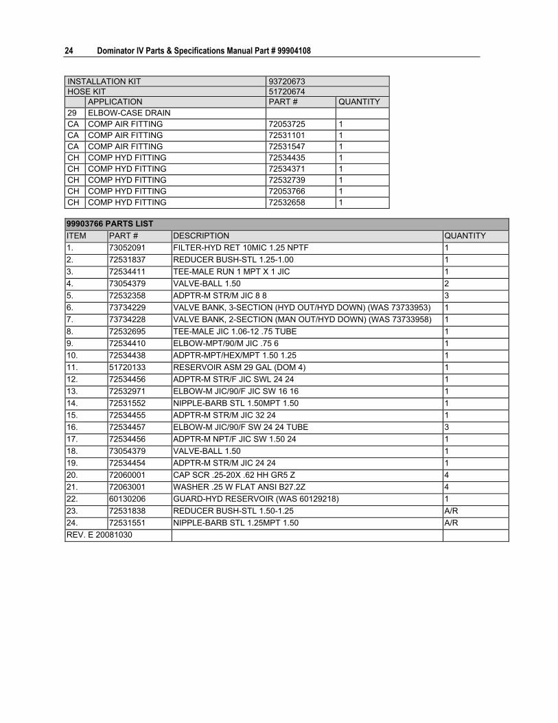
24 Dominator IV Parts & Specifications Manual Part # 99904108
INSTALLATION KIT 93720673 HOSE KIT 51720674 APPLICATION PART # QUANTITY 29 ELBOW-CASE DRAIN CA COMP AIR FITTING 72053725 1 CA COMP AIR FITTING 72531101 1 CA COMP AIR FITTING 72531547 1 CH COMP HYD FITTING 72534435 1 CH COMP HYD FITTING 72534371 1 CH COMP HYD FITTING 72532739 1 CH COMP HYD FITTING 72053766 1 CH COMP HYD FITTING 72532658 1
99903766 PARTS LIST ITEM PART # DESCRIPTION QUANTITY 1. 73052091 FILTER-HYD RET 10MIC 1.25 NPTF 1 2. 72531837 REDUCER BUSH-STL 1.25-1.00 1 3. 72534411 TEE-MALE RUN 1 MPT X 1 JIC 1 4. 73054379 VALVE-BALL 1.50 2 5. 72532358 ADPTR-M STR/M JIC 8 8 3 6. 73734229 VALVE BANK, 3-SECTION (HYD OUT/HYD DOWN) (WAS 73733953) 1 7. 73734228 VALVE BANK, 2-SECTION (MAN OUT/HYD DOWN) (WAS 73733958) 1 8. 72532695 TEE-MALE JIC 1.06-12 .75 TUBE 1 9. 72534410 ELBOW-MPT/90/M JIC .75 6 1 10. 72534438 ADPTR-MPT/HEX/MPT 1.50 1.25 1 11. 51720133 RESERVOIR ASM 29 GAL (DOM 4) 1 12. 72534456 ADPTR-M STR/F JIC SWL 24 24 1 13. 72532971 ELBOW-M JIC/90/F JIC SW 16 16 1 14. 72531552 NIPPLE-BARB STL 1.50MPT 1.50 1 15. 72534455 ADPTR-M STR/M JIC 32 24 1 16. 72534457 ELBOW-M JIC/90/F SW 24 24 TUBE 3 17. 72534456 ADPTR-M NPT/F JIC SW 1.50 24 1 18. 73054379 VALVE-BALL 1.50 1 19. 72534454 ADPTR-M STR/M JIC 24 24 1 20. 72060001 CAP SCR .25-20X .62 HH GR5 Z 4 21. 72063001 WASHER .25 W FLAT ANSI B27.2Z 4 22. 60130206 GUARD-HYD RESERVOIR (WAS 60129218) 1 23. 72531838 REDUCER BUSH-STL 1.50-1.25 A/R 24. 72531551 NIPPLE-BARB STL 1.25MPT 1.50 A/R REV. E 20081030

Chapter 2 Assemblies & Installation 25
Hydraulic Reservoir (51720133)
611,15
16
4
20
1511
16
16
1115
2
11 15
20
4
19
5
17
3
1214
7
818
5
13
9
10 (20)
NOTE: 1 MAXIMUM OIL CAPACITY OF RESERVOIR IS 30 GALLONS, WHICH INCLUDES A 10% AIR GAP. ACTUAL
TOTAL VOLUME OF RESERVOIR IS APPROXIMATELY 34 GALLONS.

26 Dominator IV Parts & Specifications Manual Part # 99904108
51720133 PARTS LIST ITEM PART # DESCRIPTION QUANTITY 1. 51719783 HARDWARE KIT-HYD INSTALL (INCL 12-14) 1 2. 52720128 RESERVOIR-WLDMT 30.00 GAL 1 3. 60130206 GUARD-HYD RESERVOIR 1 4. 60129778 COVER PLATE-RESERVOIR 2 5. 60129786 ROD-THREADED .50-13 X 11.50 2 6. 71412010 FILL-BREATHER BAYONET 1 7. 72053251 NIPPLE-PIPE BLK 1.50X CLOSE 1 8. 72053260 NIPPLE-PIPE BLK 2.00X CLOSE 1 9. 72053379 REDUCER BUSH-BLK 2.00-1.50 1 10. 72061151 SCR-SELF TAP .25X1.003PT HWH SEAL 20 11. 72062080 NUT .50-13 HEX NYLOCK 4 12. 72060001 CAP SCR .25-20X .62 HH GR5 Z 4 13. 72062301 NUT-TINNERMAN 1/4-20UNC 4 14. 72063001 WASHER .25 FLAT 4 15. 72063005 WASHER .50 FLAT 4 16. 73052001 PLUG-PIPE MAGNETIC .75NPT SQHD 3 17. 73052139 DIFFUSER-INTERNAL 55 GPM 3.00NPT
2.00NPT 1
18. 73052140 STRAINER-INTERNAL 50 GPM 3.00NPT 2.00NPT
1
19. 73052142 SIGHT GAUGE- 5" FLUID LEVEL 1 20. 76396890 GASKET-.25 X 11.63 X 5.75 (60) DURO BUNA
RUBBER 2
NEW 20061006
NOTE: IF RESERVOIR IS NOT REQUIRED, USE COVER KIT 51720648 TO COVER OPENINGS IN FLOOR.

Chapter 2 Assemblies & Installation 27
PTO Wiring Installation-2006 & 2007 (99904085) Allison T1000/T2000 TCM with Single PTO (4th Generation) (2006-7) (99904085-1)
23
7
56
77041701
TO PTO GROUND SPLICE (99903681)CHASSIS ELEC. INSTALL. INSTR.
PTO
3
IGNITION12V
1,2
3
5
E-BRAKE
80-PINCONNECTOR
ON T.C.M.
WIRE 43(143)
GM (143)
WIRE 50(150)
GM (104)
6
NOTE:
1 Different chassis may have different codes for the TCM wire numbers.
2 TCM for Freightliner is behind the dash on the passenger side of the cab. Splice into appropriate wires at that location.
3 TCM for Sterling Actera is located under the cab. Use customer access Metripack connector located on the driver's side wheel well. Use cavity "F" for pin 43 and cavity "G" for pin 50. Use item #5 terminal to connect.
4 TCM for International 4300 and 4400 models is located under the cab. Use customer access Metripack connector located in the driver's side, upper wheel well. Use cavity "B" for wire 43 and cavity "C" for wire 50. Use item #5 terminal to connect.
5 2007 and newer GM Transmission Connector (Located near upfitter connector in the engine compartment on the right side) Wire 143 = Pin C; Wire 104 = Pin K. ALLISON T1000/T2000 4th GEN SINGLE PTO WIRING PARTS LIST ITEM PART # DESCRIPTION QUANTITY 1. 77044764 FUSE HOLDER W/O FUSE 1 2. 77041527 FUSE-ATC 7.5 AMP 1 3. 77041251 RELAY 2 4. 77441047 TERMINAL, MP 150 16-18GA MALE 2 5. 77044556 DIODE 1 6. 77041701 SWITCH-ROCKER 1 NEW 20061108

28 Dominator IV Parts & Specifications Manual Part # 99904108
Allison T1000/T2000 TCM with Dual PTO (4th Generation) (2006-7) (99904085-2)
23
7
56
23
7
56
IGNITION12 V
1,2
4
3E-BRAKE
80-PINCONNECTOR
ON T.C.M.
WIRE 43�(143)
GM (143)WIRE 50
(150)GM (104)
COMPRESSORSWITCH
CRANESWITCH
77041701
77041701
6
6
3
4
COMPRELAY
CRANERELAY
PTOSOLENOID
4
PTO
PTO
CMPRSRPTO
CRANEPTO
TO PTO GROUND SPLICE(REF 99903681-CHASSISELEC. INSTL. INSTRUCTIONS)
NOTE:
1 Different chassis may have different codes for the TCM wire numbers.
2 TCM for Freightliner is behind the dash on the passenger side of the cab. Splice into appropriate wires at that location.
3 TCM for Sterling Actera is located under the cab. Use customer access Metripack connector located on the driver's side wheel well. Use cavity "F" for pin 43 and cavity "G" for pin 50. Use item #5 terminal to connect.
4 TCM for International 4300 and 4400 models is located under the cab. Use customer access Metripack connector located in the driver's side, upper wheel well. Use cavity "B" for wire 43 and cavity "C" for 50. Use item #5 terminal to connect.
5 2007 and newer GM Transmission Connector (Located near upfitter connector in the engine compartment on the right side) Wire 143 = Pin C; Wire 104 = Pin K. ALLISON T1000/T2000 4th GEN DUAL PTO WIRING PARTS LIST ITEM PART # DESCRIPTION QUANTITY 1. 77044764 FUSE HOLDER W/O FUSE 1 2. 77041527 FUSE-ATC 7.5 AMP 1 3. 77044556 DIODE - 2.2 AMP/ 274 V 3 4. 77041251 RELAY 3 5. 77441047 TERMINAL, MP 150 16-18GA MALE 2 6. 77041701 SWITCH-ROCKER 2 NEW 20061108

Chapter 2 Assemblies & Installation 29
Allison T3000/T4000 TCM with Single PTO (4th Generation) (2006-7) (99904085-3)
23
7
56
IGNITION12 V
1,2
53
E-BRAKE
PTO
3
3
PIN 45(145)
PIN 17(117)
PIN 3(103)
80 PINCONNECTOR
ON T.C.M.
6
77041701
TO PTO GROUND SPLICE(REF 99903681-CHASSISELEC. INSTALL. INSTRUCTIONS)
NOTE:
1 Different chassis may have different codes for the TCM wire numbers.
2 TCM for Freightliner is behind the dash on the passenger side of the cab. Splice into appropriate wires at that location.
3 2007 and newer GM Transmission Connector (Located near upfitter connector in the engine compartment on the right side) Pin 45 = Pin A; Pin 17 = Pin B; Pin 3 = Pin J ALLISON T3000/T4000 4th GEN SINGLE PTO WIRING PARTS LIST ITEM PART # DESCRIPTION QUANTITY 1. 77044764 FUSE HOLDER W/O FUSE 1 2. 77041527 FUSE-ATC 7.5 AMP 1 3. 77041251 RELAY 2 4. 77441047 TERMINAL MP 150 16-18GA 3 5. 77044556 DIODE - 2.2 AMP/ 274 V 1 6. 77041701 SWITCH-ROCKER 1 NEW 20061108

30 Dominator IV Parts & Specifications Manual Part # 99904108
Allison T3000/T4000 TCM with Dual PTO (4th Generation) (2006-7) (99904085-4)
23
7
56
23
7
56
IGNITION12 V
1,2
4
3E-BRAKE
80 PINCONNECTOR
ON T.C.M.
COMPRESSORSWITCH
CRANESWITCH
6
6
PIN 45(145)
PIN 17(117)
PIN 3(103)
3
COMPRELAY
CRANERELAY
PTOSOLENOID
4CMPRSR
PTO
CRANEPTO
TO PTO GROUND SPLICE(REF 99903681-CHASSISELEC. INSTL. INSTRUCTIONS)
4
4
NOTE:
1 Different chassis may have different codes for the TCM wire numbers.
2 TCM for Freightliner is behind the dash on the passenger side of the cab. Splice into appropriate wires at that location.2
3 007 and newer GM Transmission Connector (Located near upfitter connector in the engine compartment on the right side) Pin 45 = Pin A; Pin 17 = Pin B; Pin 3 = Pin J ALLISON T3000/T4000 4th GEN DUAL PTO WIRING PARTS LIST ITEM PART # DESCRIPTION QUANTITY 1. 77044764 FUSE HOLDER W/O FUSE 1 2. 77041527 FUSE-ATC 7.5 AMP 1 3. 77044556 DIODE - 2.2 AMP/ 274 V 3 4. 77041251 RELAY 4 5. 77441047 TERMINAL, MP 150 16-18GA MALE REF 6. 77041701 SWITCH-ROCKER 2 NEW 20061108

Chapter 2 Assemblies & Installation 31
Allison T1000/T2000 TCM Freightliner - Single PTO (4th Generation) (2006-7) (99904085-5)
PTO ENGAGE(IMT HARNESS)
2 200 1413 (PURPLE)
TO FREIGHTLINERHARNESS (BACK OFCAB) CONNECTIONTO PTO PRESSURESWITCHGROUND (BLACK)
2 PIN CONNECTORPTO
PTOPRESSURE
SWITCH
80-PINCONNECTOR
ON T.C.M.
WIRE 43(143)
WIRE 50(150)
E-BRAKE
1
1
200D 151T(PURPLE) GROUND (BLACK)
2 PIN CONNECTOR
TO FREIGHTLINER HARNESS�(BACK OF CAB) CONNECTION TO
PTO SOLENOID CONNECTOR
ALLISON T1000/T2000 4th GEN FREIGHTLINER PTO WIRING PARTS LIST ITEM PART # DESCRIPTION QUANTITY 1. 77041251 RELAY 2 2. 77044556 DIODE - 2.2 AMP/ 274 V 2 NEW 20061108

32 Dominator IV Parts & Specifications Manual Part # 99904108
PTO Wiring Installation Through 2005 (99903409)
Allison T1000/T2000 TCM with Single PTO Through 2005 (99903409-1)
IGNITION12V
1,2
3
5E-BRAKE
SUPPLIEDWITH PTO
PTOLAMP
SWITCH
GREYCONNECTOR
ON TCM
WIREJ1-06WIREJ1-19
3 PTO
PTOPRESSSWITCH
NOTE:
1 Different chassis may have different codes for the TCM wire numbers.
2 TCM for Freightliner is behind the dash on the passenger side of the cab. Splice into appropriate wires at that location.
3 TCM for Sterling Actera is located under the cab. Use customer access Metripack connector located on the driver's side wheel well. Use cavity "F" for wire J1-06 and cavity "G" for wire J1-19. Use item #4 terminal to connect.
4 TCM for International 4300 and 4400 models is located under the cab. Use customer access Metripack connector located in the driver's side, upper wheel well. Use cavity "B" for wire J1-06 and cavity "C" for J1-19. Use item #4 terminal to connect.
5 GM Transmission Connector (Located near upfitter connector in the engine compartment on the right side) Wire 106 = Pin B; Wire 119 = Pin J ALLISON T1000/T2000 SINGLE PTO WIRING PARTS LIST ITEM PART # DESCRIPTION QUANTITY 1. 77044764 FUSE HOLDER W/O FUSE 1 2. 77041527 FUSE-ATC 7.5 AMP 1 3. 77041251 RELAY 1 4. 77441047 TERMINAL, MP 150 16-18GA MALE 2 5. 77044556 DIODE, 2.2 AMP 1
REV. B 20050519

Chapter 2 Assemblies & Installation 33
Allison T1000/T2000 TCM with Dual PTO Through 2005 (99903409-2)
IGNITION12V
1,2
3E-BRAKE
SUPPLIEDWITH PTO
COMP. PTOLAMP
COMPRESSSWITCH
GREYCONNECTOR
ON TCM
WIREJ1-06WIREJ1-19
3
PTOPRESSSWITCH
4
CRANEPTO LAMP
CRANESWITCH
4
4
COMPRELAY
CRANERELAY
CRANEPTO
PTO
COMPRESSORPTO
PTO
PTOPRESSSWITCH
PTOSOLENOID
NOTE:
1 Different chassis may have different codes for the TCM wire numbers.
2 TCM for Freightliner is behind the dash on the passenger side of the cab. Splice into appropriate wires at that location.
3 TCM for Sterling Actera is located under the cab. Use customer access Metripack connector located on the driver's side wheel well. Use cavity "F" for wire J1-06 and cavity "G" for wire J1-19. Use item #5 terminal to connect.
4 TCM for International 4300 and 4400 models is located under the cab. Use customer access Metripack connector located in the driver's side, upper wheel well. Use cavity "B" for wire J1-06 and cavity "C" for J1-19. Use item #4 terminal to connect.
5 GM Transmission Connector (Located near upfitter connector in the engine compartment on the right side) Wire 106 = Pin B; Wire 119 = Pin J ALLISON T1000/T2000 DUAL PTO WIRING PARTS LIST ITEM PART # DESCRIPTION QUANTITY 1. 77044764 FUSE HOLDER W/O FUSE 1 2. 77041527 FUSE-ATC 7.5 AMP 1 3. 77044556 DIODE - 2.2 AMP 2 4. 77041251 RELAY 2 5. 77441047 TERMINAL, MP 150 16-18GA MALE 2
REV. B 20050519

34 Dominator IV Parts & Specifications Manual Part # 99904108
Allison T3000/T4000 TCM with Single PTO Through 2005 (99903409-3)
PIN 2
PIN 30
PIN 313
GRAYCONNECTOR
ON TCM
3
1,2
35
E-BRAKESWITCH
PTO LAMP
IGNITION12V
SUPPLIED WITH PTO
PTOPRESSURESWITCH
PTOPTO
NOTE:
1 Different chassis may have different codes for the TCM wire numbers.
2 TCM for Freightliner is behind the dash on the passenger side of the cab. Splice into appropriate wires at that location.
3 GM transmission connector (located near the GM upfitter connector in the engine compartment on the right side); Pin 2 = Pin A, Pin 30 = Pin B, Pin 31 = Pin J ALLISON T3000/T4000 SINGLE PTO WIRING PARTS LIST ITEM PART # DESCRIPTION QUANTITY 1. 77044764 FUSE HOLDER W/O FUSE 1 2. 77041527 FUSE-ATC 7.5 AMP 1 3. 77041251 RELAY 2 4. 77441047 TERMINAL, MP 150 16-18GA MALE 3
REV. B 20050519

Chapter 2 Assemblies & Installation 35
Allison T3000/T4000 TCM with Dual PTO Through 2005 (99903409-4)
IGNITION12V
1,2
3E-BRAKE
SUPPLIEDWITH PTO
COMP. PTOLAMP
COMPRESSSWITCH
GREYCONNECTOR
ON TCM
PIN 2
PIN 30
4CRANEPTO LAMP
CRANESWITCH
PIN 31
4
43
CRANERELAY
COMPRELAY
4
PTOSOLENOID
PTOCOMPRESSORPTO
PTOCRANEPTO
PTOPRESSSWITCH
PTOPRESSSWITCH
NOTE:
1 Different chassis may have different codes for the TCM wire numbers.
2 TCM for Freightliner is behind the dash on the passenger side of the cab. Splice into appropriate wires at that location.
3 GM transmission connector (located near the GM upfitter connector in the engine compartment on the right side); Pin 2 = Pin A, Pin 30 = Pin B, Pin 31 = Pin J
4 Use item #5 to connect. ALLISON T3000/T4000 DUAL PTO WIRING PARTS LIST ITEM PART # DESCRIPTION QUANTITY 1. 77044764 FUSE HOLDER W/O FUSE 1 2. 77041527 FUSE-ATC 7.5 AMP 1 3. 77044556 DIODE 2.2 AMP 2 4. 77041251 RELAY 2 5. 77441047 TERMINAL, MP 150 16-18GA MALE REF
REV. B 20050519

36 Dominator IV Parts & Specifications Manual Part # 99904108
Allison T1000/T2000 TCM with Single PTO on Freightliner with PTO Dash Switch Through 2005 (99903409-5)
TO FREIGHTLINER HARNESS (BACK OF CAB)CONNECTION TO PTO SOLENOID CONNECTOR
200D 151T (PURPLE)
200 1413 (PURPLE)2
PTO ENGAGE(IMT HARNESS)
GROUND (BLACK) 2 PIN CONNECTOR
1
E-BRAKE
TO FREIGHTLINERHARNESS (BACK OF CAB)CONNECTION TO PTOPRESSURE SWITCH
GROUND (BLACK) 2 PIN CONNECTOR
PTOPRESSURE
SWITCH
PTO1
GREYCONNECTORON TCM
WIREJ1-06WIREJ1-19
ALLISON T1000/T2000 TCM SINGLE PTO ON FREIGHTLINER WITH PTO DASH SWITCH ITEM PART # DESCRIPTION QUANTITY 1. 77041251 RELAY 2 2. 77044556 DIODE, 2.2 AMP 2
REV. B 20050519

Chapter 2 Assemblies & Installation 37
PTO/Pump Rotation Guide (99904279)
FRONTOFTRUCK
PTO ROTATION IS OPPOSITE OF ENGINE ROTATION (OPP)
FRONTOFTRUCK
CW
LOOKING FROM REAROF TRUCK, PTOROTATES CW
LOOKING FROM FRONTOF TRUCK, PUMP / DRIVEEQUIPMENT ROTATES CCW
LOOKING FROM REAROF TRUCK, PTOROTATES CCW
LOOKING FROM FRONTOF TRUCK, PUMP / DRIVEEQUIPMENT ROTATES CW
CCW
LOOKINGAT PUMPSHAFT
LOOKINGAT REAROF PUMP
CW CCW
P SPS
LOOKINGAT PUMPSHAFT
LOOKINGAT REAROF PUMP
CCW CW
P S PS
PTO ROTATION IS THE SAME AS ENGINE ROTATION (ENG) NOTES: 1 The pump / driven equipment should always rotate in the opposite direction of the PTO.
2 A geared adapter will always change the rotation of the PTO.

38 Dominator IV Parts & Specifications Manual Part # 99904108
Compressor Mounting Locations (99903712)
CAS435HA Compressor Mounting Locations
CAS435HA INSTALLATION ON SERIES 1 AND SERIES 2 DOMINATOR
4.40"
13.38"12.75" 12.00"
ø0.44" TYP (4)
4.40"
13.38"
18.75" 12.00"ø0.44" TYP (4)
CAS435HA INSTALLATION ON SERIES 2DOMINATOR WITH HEADACHE RACKAND STANDARD HEIGHT SIDEPACKON COMPRESSOR SIDE
NOTE: When installing a compressor, maintain a minimum clearance of 8" on each end of the compressor. If installing a compressor with a hydraulic aftercooler, maintain a minimum space of 10" between the compressor and aftercooler, while still maintaining the 8" of clearance on each end of the compressor-cooler combination.

Chapter 2 Assemblies & Installation 39
CAS2545 & CAS3560 Compressor Mounting Locations
CAS3560 & CAS2545 INSTALLATION ON SERIES 2 DOMWITH HEADACHE RACK, STANDARD HEIGHT SIDEPACKON COMPRESSOR SIDE, AND TELESCOPIC ROOF.
4.38"12.25"
16.5" 6" 12"18" MIN.
ø0.44"TYP (10)
4.38"12.25"
16.50"12.00"
12.00"6.00"
18.00" MIN.ø0.44" TYP (10)
CAS3560 & CAS2545 INSTALLATION ON SERIES 2 DOMWITH HEADACHE RACKAND STANDARD HEIGHTSIDEPACK ONCOMPRESSOR SIDE
CAS3560 & CAS2545 INSTALLATION ON SERIES 1 ANDSERIES 2 DOMINATORS
4.38"12.25"
10.50"12.00"
12.00"
6.00"18.00" MIN.
ø0.44" TYP (10)
NOTE: When installing a compressor, maintain a minimum clearance of 8" on each end of the compressor. If installing a compressor with a hydraulic aftercooler, maintain a minimum space of 10" between the compressor and aftercooler, while still maintaining the 8" of clearance on each end of the compressor-cooler combination.

40 Dominator IV Parts & Specifications Manual Part # 99904108
Weather-Strip Installation (99904256) WEATHER-STRIP:TOP WILL CAP THE SIDE.
GAP BETWEENWEATHER-STRIPAND DOOR JAMIS ACCEPTABLE.
VIEW A-A
A
WEATHER-STRIPFLUSH WITH DOOROPENING.
WEATHER-STRIPBOTTOM IS UNDERTHE SIDE.
B
B

Chapter 2 Assemblies & Installation 41
Battery Cover Installation (99904452)
6
78
7
5
109
4
8
11
1 2
NOTE: BATTERY COVERNOT SHOWN FOR CLARITY.
CHASSIS BATTERIESRELOCATED TO COMPARTMENT.
99904452 PARTS LIST ITEM PART # DESCRIPTION KIT # QUANTITY 1. 77041733 STUD-ELEC PASS THROUGH .38 RED REF 2. 77041774 STUD-ELEC PASS THROUGH .38 BLK REF 3. 51721742 HARDWARE KIT-BATTERY COVER 1 4. 60133203 BRACKET-BATTERY COVER MOUNT 1 5. 60133202 COVER-BATTERY DOM COMPARTMENT 1 6. 70039108 LATCH-RUBBER T-HANDLE #3 2 7. 72601940 CAP SCR .10-24X .50 BTNHD ZC #3 8 8. 72062106 NUT 10-24 HEX NYLOCK #3 8 9. 72063002 WASHER .31 FLAT #3 2 10. 72062109 NUT .31-18 HEX NYLOCK #3 2 11. 72060023 CAP SCR .31-18X .75 HH GR5 Z #3 2 REV. A 20080904

42 Dominator IV Parts & Specifications Manual Part # 99904108

43
In This Chapter Shelf Installation Drawing (99904062) .......................................44 Compartment Layout (99904062) ..............................................45 Installation Drawing, Door Trays (99903667).............................48 Parts List, Drawer Units and Kits................................................49 Dominator IV Drawer Set Reference Drawing............................51 Drawer Components ..................................................................52 Compartment Options ................................................................54 Tool Box Tray (51711548)..........................................................54 Tank Bracket, 2-Bottle (51719752) ............................................56 Tank Bracket, 3-Bottle (51720021) ............................................57 Pull-Out Bin Sets ........................................................................57
C H A P T E R 3
Compartment Options

44 Dominator IV Parts & Specifications Manual Part # 99904108
Shelf Installation Drawing (99904062)
A
B
11 12
13
1
2
4 5,6,7
(4 PER PANEL (TYP))5,6,7(4 PER
PANEL (TYP))
8,9,10
DETAIL A DETAIL B
SHELF DIVIDERS(PART OF DIVIDEDSHELF KITS)
FULLWIDTHSHELF
COMPARTMENTDIVIDERS
99904062 PARTS LIST ITEM PART # DESCRIPTION 1. SEE COMPARTMENT LAYOUT
CHART (see "Compartment Layout (99904062)" on page 45)
SHELF
2. SEE COMPARTMENT LAYOUT CHART
SHELF END #2
3. SEE COMPARTMENT LAYOUT CHART
SHELF END #1

Chapter 3 Compartment Options 45
99904062 PARTS LIST ITEM PART # DESCRIPTION 4. SEE COMPARTMENT LAYOUT
CHART DIVIDER PANEL
5. 72060023 CAP SCR .31-18X.75 HHGR5Z 6. 72062109 NUT .31-18 HEX NYLOC 7. 72063002 WASHER .31 FLAT 8. 72062167 NUT-SS .31-18 HEX NYLOC 9. 72062314 WASHER-SS BONDED PLTD .31 10. 72601831 CAP SCR-SS .31-18X1 HH 11. 51720216 DIVIDER KIT-BOLT ON DOM 20" H D4 12. 51720126 DIVIDER KIT-BOLT ON 44" & 52" SIDEPACK 13. 51720127 DIVIDER KIT-BOLT ON 60" REV A 20070111

46 Dominator IV Parts & Specifications Manual Part # 99904108
Compartment Layout (99904062)
LR LH2 LH1 LV2 LV1
RH2 RH1 RV2 RV1
COMPARTMENTS LEFT SIDE COMPARTMENT COMPONENTS COMPARTMENT LOCATION
ITEM #3 - SHELF END
ITEM #1 - SHELF
ITEM #2 - SHELF END
SHELF WIDTH (INCHES)
SHELF DEPTH (INCHES)
SHELF DIVIDER (60251115 )
SHELF KIT NUMBER
LEFT VERTICAL 1 (LV1)
60126425 60130473 60126424 41 19 51720488
60126425 60130474 60126424 41 19 6 INCLUDED 51720489 LEFT VERTICAL 2 (LV2)
60126429 60130475 60126424 37.38 19 51720490
60126429 60130476 60126424 37.38 19 4 INCLUDED 51720491 LEFT HORIZONTAL 14' LH (LH1)
60126423 60129822 60126429 52 19 51720200
60126423 60129825 60126429 52 19 10 INCLUDED 51720201 LEFT HORIZONTAL 19' (LH1)
60126423 60129956 60126429 55.5 19 51720284
60126423 60129957 60126429 55.5 19 10 INCLUDED 51720285 LEFT HORIZONTAL 19' (LH2)
60126423 60129956 60126429 55.5 19 51720284
60126423 60129957 60126429 55.5 19 10 INCLUDED 51720285 LEFT REAR (LR)
60126423 60129821 60126697 32 19 51720202
60126423 60129820 60126697 32 19 5 INCLUDED 51720203

Chapter 3 Compartment Options 47
RIGHT SIDE COMPARTMENT COMPONENTS COMPARTMENT LOCATION
ITEM #3 - SHELF END
ITEM #1 - SHELF
ITEM #2 - SHELF END
SHELF WIDTH (INCHES)
SHELF DEPTH (INCHES)
SHELF DIVIDER (60251228)
SHELF KIT NUMBER
RIGHT VERTICAL 1 (RV1)
60132731 60130477 60129841 41 21 51720492
60132731 60130478 60129841 41 21 6 INCLUDED 51720493 RIGHT VERTICAL 2 (RV2)
60132731 60130479 60129834 37.38 21 51720494
60132731 60130480 60129834 37.38 21 6 INCLUDED 51720495 RIGHT HORIZONTAL 14' LH (RH1)
60129830 60130218 60130217 48.38 21 51720214
60129830 60130219 60130217 48.38 21 10 INCLUDED 51720215 RIGHT HORIZONTAL 19' (RH1)
60132731 60129958 60129830 55.0 21 51720286
60132731 60129959 60129830 55.0 21 10 INCLUDED 51720287 RIGHT HORIZONTAL 19' (RH2)
60129830 60130220 60130220 52 21 51720288
60129830 60130221 60130217 52 21 10 INCLUDED 51720289 DIVIDER PANEL COMPONENTS DIVIDER PANELS
ITEM #3 - SHELF END
ITEM #1 - SHELF
ITEM #2 - SHELF END
SHELF WIDTH (INCHES)
SIDEPACK SHELF DIVIDER
SHELF KIT NUMBER
22" DIVIDER PANEL
60132731 60126313 60126267 11.5 SHELVES INCLUDED
51720216
60132731 60129733 60129732 11.5 51720217 60132731 60129734 60129732 11.5 60251213 (3) 51270218 60132731 60129737 60129732 17.5 51720219
40" TALL DIVIDER PANEL (51720126)
60132731 60129738 60129732 17.5 60251115 (4) 51720220 60132731 60129733 60129732 11.5 51720217 60132731 60129734 60129732 11.5 60251213 (3) 51720218 60132731 60129737 60129732 17.5 51720219
56" TALL DIVIDER PANEL (51720127)
60132731 60129738 60129732 17.5
RIGHT HAND
60251115 (4) 51720220 22" DIVIDER PANEL
60129832 60126313 60126267 11.5 SHELVES INCLUDED
51718229
60129832 60129733 60129732 11.5 51720122 60129832 60129734 60129732 11.5 60251213 (3) 51270123 60129832 60129737 60129732 17.5 51720124
40" TALL DIVIDER PANEL (51720126)
60129832 60129738 60129732 17.5 60251115 (4) 51720125 60129832 60129733 60129732 11.5 51720122 60129832 60129734 60129732 11.5 60251213 (3) 51270123 60129832 60129737 60129732 17.5 51720124
56" TALL DIVIDER PANEL (51720127) REV C 20090713
60129832 60129738 60129732 17.5
LEFT HAND
60251115 (4) 51720125

48 Dominator IV Parts & Specifications Manual Part # 99904108
Installation Drawing, Door Trays (99903667)
A
7
9
9
3
65
4
8
2
1
10
8.25"TYP
8.25"TYP
3"3" 3"
3"
3"
3"
8.25"TYP
3" 3"
38.89" 31.88" 27.63" 26.5" 23.5"
DETAIL A
HARDWAREPER TRAY:72062307 (4 TYP)72601818 (4 TYP)DRILL AT ASSEMBLY.
20.5" 19" 19"
NOTE:
1 Position all tray applications 3.0" above latch hole opening. Space all double tray applications 8.25" apart. 99903667 PARTS LIST ITEM PART # KIT # DESCRIPTION QUANTITY1. 52720635 51720645 TRAY-TORCH DOM 31.88 W-LATCH REF 2. 52720636 51720646 TRAY-SPRAY CAN DOM 31.88 W DOOR REF 3. 52718839 51718838 TRAY-TORCH DOM 31.88 W-LATCH REF 4. 52718841 51718840 TRAY-SPRAY CAN DOM 31.88 W DOOR REF 5. 52720227 51720230 TRAY-SPRAY CAN DOM 27.63 W DOOR REF 6. 52720226 51720229 TRAY-SPRAY CAN DOM 26.50 W DOOR REF 7. 52720225 51020228 TRAY-SPRAY CAN DOM 23.5 W DOOR REF 8. 52719152 51719166 TRAY-SPRAY CAN DOM 20.50 W DOOR REF 9. 52719153 51719167 TRAY-SPRAY CAN DOM 19.00 W DOOR REF 10. 52713972 51713973 TRAY-WELDMENT TORCH DOM 19" W/LATCH REF NOTE: Not all trays are available on all models. Check the door widths on your model to determine appropriate options. REV. D 20081112

Chapter 3 Compartment Options 49
Parts List, Drawer Units and Kits
LR LH2 LH1 LV2 LV1
RH2 RH1 RV2 RV1
COMPARTMENTS Compartment Key LR Left Rear RH Right Horizontal LH Left Horizontal RV2 Right Vertical 2 LV2 Left Vertical 2 RV1 Right Vertical 1 LV1 Left Vertical 1
The body configuration determines the rollout drawer sets which can be used in each body. COMPARTMENT BODY LENGTH DRAWER SET WIDTH LEFT & RIGHT VERTICAL 1 14', 19' 26" Wide LEFT & RIGHT VERTICAL 2 14', 19' 13" Wide or 26" Wide LEFT & RIGHT HORIZONTAL
14', 19' 39" Wide
LEFT REAR 14', 19' 13" Wide

50 Dominator IV Parts & Specifications Manual Part # 99904108
DRAWER SET WIDTH
COMPARTMENT APPLICATION
PART # 3" HIGH DRAWERS
5" HIGH DRAWERS
7" HIGH DRAWERS
DRAWER SET OVERALL HEIGHT
70733765 5 22" 70733766 3 21" 70733767 3 1 21" 70733768 3 15" 70733769 2 1 23" 70733780 5 2 1 41" 70733784 5 3 39" 70733786 3 2 1 34" 70733787 3 2 1 40" 70733788 8 1 39" 70733789 6 1 31" 70733791 3 3 32"
13" WIDE
LEFT & RIGHT VERTICAL 2, LEFT REAR
70733793 3 4 38" 70733774 5 22" 70733775 3 21" 70733776 3 1 21" 70733777 3 15" 70733778 2 1 23" 70733779 5 2 1 41" 70733781 3 2 1 34" 70733782 8 1 39" 70733783 5 1 40" 70733785 5 3 39" 70733790 6 1 31" 70733792 3 3 32"
26" WIDE
LEFT & RIGHT VERTICAL 1, LEFT & RIGHT VERTICAL 2
70733794 3 4 38" 70733770 5 22" 70733771 3 21" 70733772 3 1 21"
39" WIDE
LEFT & RIGHT HORIZONTAL COMPARTMENTS 70733773 2 1 23"

Chapter 3 Compartment Options 51
Dominator IV Drawer Set Reference Drawing
2
1
3
4
7
6
5
8
8
RISER
1
WIDTH
HEIGHT
3.0" DEPTH HEIGHT
SAMPLE DRAWER SETDRAWING WITH 3",5", AND 7" HIGH DRAWERS.
1
3
48
8
SAMPLE DRAWINGWITH 3" DRAWERS ONLY
NOTE: 1 Complete drawer set part numbers are included in Parts List, Drawer Units and Kits (on page 49).
2 The quantity of items 1- 5, panels, risers, and shelves, is 1 per drawer set.
3 The quantities of items 6 - 11, slides and drawers, are based on the number of drawers in the complete kits. drawer slides.

52 Dominator IV Parts & Specifications Manual Part # 99904108
ITEM DESCRIPTION 13" SET 26" SET 39" SET 1. PANEL-SIDE, LH REF REF REF 2. PANEL-SIDE, RH REF REF REF 3. RISER 60130555 60130556 60130557 4. SHELF 60130552 60130553 60130554 5. PANEL-DRAWER BACK REF REF REF 6. DRAWER SLIDE W-TABS LH 70734171 70734171 70734171 7. DRAWER SLIDE W-TABS RH 70734173 70734173 70734173 8. SHELF-ADJUSTABLE END 60130659 60130659 60130660 9. 3" DRAWER 70733800 70733798 70733804 10. 5" DRAWER 70733802 70733799 70733805 11. 7" DRAWER 70733803 70733801 70733806

Chapter 3 Compartment Options 53
Drawer Components
1(DIVIDER)
4(LOCK)
SAMPLE DRAWING - DRAWER WITH 4 DIVIDERS
4(LOCK)
3(DIVIDER-HEMMED)
1(DIVIDER)
2(DIVIDER-CENTER)
SAMPLE DRAWING - DRAWER WITH CENTER AND SIDE DIVIDERS
NOTE: 1 All drawers are painted.
2 Each IMT drawer comes with the standard lock 70734188. Optional replacement drawer lock sets are available for IMT drawers. Replacement lock sets 70734420 and 70734421 can be ordered from IMT customer service.
DRAWER COMPONENT PART NUMBERS (QUANTITY IN PARENTHESES)
DRAWER PART #
DRAWER WITH DIVIDER DIMENSIONS
ITEM 1-DIVIDER ITEM 2- DIVIDER, CENTER
ITEM 3- DIVIDER, HEMMED
70733800 3" H X 13" W 60251081 (4) 70733802 5" H X 13" W 60251233 (4) 70733803 7" H X 13" W 60251233 (4) 70733798 3" H X 26" W 60251081 (6) 60130560 (1) 60130558 (2) 70733799 5" H X 26" W 60251233 (6) 60130561 (1) 60130559 (2) 70733801 7" H X 26" W 60251233 (6) 60130561 (1) 60130559 (2) 70733804 3" H X 39" W 60251081 (9) 60130560 (2) 60130571 (2) 70733805 5" H X 39" W 60251233 (9) 60130561 (2) 60130572 (2) 70733806 7" H X 39" W 60251233 (9) 60130561 (2) 60130572 (2)

54 Dominator IV Parts & Specifications Manual Part # 99904108
Compartment Options Part # Dimensions / Description Compartments Available Roll-out Tool Box Tray 51711548 Tray dimensions – 32"W x 18.5"D LV1, LV2, RV1, RV2 Oxygen / Acetylene Tank Bracket 51720021 Tank bracket – Oxy/Acet 3 tanks with hook LV1, RV1 51719752 Tank bracket – Oxy/Acet 2 tanks with hook
(Mounted on front wall in vented compartment) LV1, RV1
Pull-out Drawer Sets 51704193 4 drawer set with base 18"D x 8.12"W x 19"H LV1, LV2, LV3, RV1, RV2, RV3, LH, RH,
LR 51704194 5 drawer set with base 18"D x 8.12"W x 23"H LV1, LV2, LV3, RV1, RV2, RV3, LR 51709946 16 bolt drawer set w/base 18"D x 16.25"W x
35.5"H LV1, LV2, LV3, RV1, RV2, RV3, LR
51704282 18 bolt drawer set w/base 18"D x 16.25"W x 39.5"H
LV1, LV2, LV3, RV1, RV2, RV3, LR
51712650 2 drawer set with base 18"D x 8.12"W x 11"H LV1, LV2, LV3, RV1, RV2, RV3, LH, RH, LR
Slide-out Parts Book Tray 51713240 Slide out parts / book tray LH, RH Bookshelf 51710102 Bookshelf dimensions 8"H x 45"L x 12"D RH, LH 51707629 Bookshelf dimensions 8"H x 26"L x 12"D RH, LH Note: Left Vertical Compartment 3 (LV3) and Right Vertical Compartment 3 (RV3) are only available on Dominator I and II 13' and 14' models, and may not be available on your model. Check your product specifications.

Chapter 3 Compartment Options 55
Tool Box Tray (51711548)
2,5,6,8
1
4,5,6,8
3,5,6,79,10,11
51711548 PARTS LIST ITEM PART # DESCRIPTION QUANTITY 1. 52711606 TRAY 16-3/4 X 32 1 2. 60117163 MTG BRACKET 32" 1 3. 60114300 MTG BRACKET 2 4. 70731440 DRAWER SLIDE 2 5. 72062106 NUT #10-24 LOCK 19 6. 72063123 WASHER #10 WRT 19 7. 72601284 MACH SCR #10-24 X 5/8 FLHD 8 8. 72601283 MACH SCR #10-24 X 5/8 RDHD 11 9. 72601329 CAP SCR 5/16-18X3/4 BTNHD 4 10. 72063002 WASHER 5/16 WRT 4 11. 72062109 NUT 5/16-18 LOCK 4
REV. A 20041230

56 Dominator IV Parts & Specifications Manual Part # 99904108
Tank Bracket, 2-Bottle (51719752)
2
3
1
9
8
4,5,6 (6 PLCS)6,7,10 (4 PLCS)
51719752 PARTS LIST ITEM PART # DESCRIPTION QUANTITY 1. 52704224 HOOK-WLDMT (J) (BOLT IN) 1 2. 60129198 BRACKET ACET BOTTLE 1 3. 60129197 BRACKET OXY BOTTLE 1 4. 72063001 WASHER .25 FLAT 12 5. 72060025 CAP SCR .31-18X 1.00 HH GR5 Z 6 6. 72062109 NUT .31-18 HEX NYLOCK 10 7. 72063002 WASHER .31 FLAT 4 8. 70733516 STRAP-36" BOTTLE HOLDER W/ SNAP HOOK 1 9. 70058959 CHAIN CONNECTOR-THREADED .19 2 10. 72060023 CAP SCR .31-18X .75 HH GR5 Z 4 REV A 20080417

Chapter 3 Compartment Options 57
Tank Bracket, 3-Bottle (51720021) Reference the 51719752 drawing for the Tank Bracket, 2-Bottle. The Tank Bracket, 3-Bottle, has an additional bracket 60129198 for the oxygen bottle. 51720021 PARTS LIST ITEM PART # DESCRIPTION QUANTITY 1. 52704224 HOOK-WLDMT (J) (BOLT IN) 1 2. 60129198 BRACKET ACET BOTTLE 1 3. 60129197 BRACKET OXY BOTTLE 2 4. 72063001 WASHER .25 FLAT 10 5. 72060025 CAP SCR .31-18X 1.00 HH GR5 Z 6 6. 72062109 NUT .31-18 HEX NYLOCK 10 7. 72063002 WASHER .31 FLAT 4 8. 70733516 STRAP-36" BOTTLE HOLDER W/ SNAP HOOK 1 9. 70058959 CHAIN CONNECTOR-THREADED .19 2 10. 72060023 CAP SCR .31-18X .75 HH GR5 Z 4 REV 20061107

58 Dominator IV Parts & Specifications Manual Part # 99904108
Pull-Out Bin Sets Pull-out bins are available for IMT Dominators in sets of 2, 4, 5, 16, and 18 units. BIN SET PARTS LISTS # BINS / QUANTITY ITEM PART # DESCRIPTION 2-BINS
(51712650) 4-BINS (51704193)
5-BINS (51704194)
16-BINS (51709946)
18-BINS (51704282)
1. 52712651 CABINET (2-BIN SET) 1 52710227 CABINET (4-BIN SET) 1 52710226 CABINET (5-BIN SET) 1 52710235 CABINET (16-BIN SET) 1 52710234 CABINET (18-BIN SET) 1 2. 52710274 BIN 2 4 5 16 18 3. 60114979 DIVIDER 3.38X7.62 8 12 15 48 54 4. 72060002 CAP SCR 1/4-20X3/4 HHGR5 4 4 4 8 8 5. 72062104 NUT 1/4-20 LOCK 4 4 4 8 8 6. 72063001 WASHER 1/4 WRT 8 8 8 16 16
2-Bin Set with Base (51712650)
3
2
1ITEMS 4,5,6 NOT SHOWN

Chapter 3 Compartment Options 59
4-Bin Set with Base (51704193)
3
2
1
ITEMS 4-7 NOT SHOWN
5-Bin Set with Base (51704194)
1
ITEMS 4,5,6 NOT SHOWN
2
3
16-Bin Set with Base (51709946)
1
2
3
ITEMS 4,5,6NOT SHOWN
18-Bin Set with Base (51704282)
1
2
3
ITEMS 4,5,6NOT SHOWN


61
In This Chapter Tailgate Assembly (51718801)...................................................61 Bumper Hitch & Workbench Options..........................................63
C H A P T E R 4
Tailgate & Bumper Options

62 Dominator IV Parts & Specifications Manual Part # 99904108
Tailgate Assembly (51718801)
7
28
151
6
15
8
3TAILGATE ASSEMBLY
9,119,10
BOTTOM SPRINGCONNECTION
15
18
TAILGATE INSTALLATION
12,13,14
15
17
12,13,14
TO EXISTING HOLES IN BODY
TO EXISTING HOLES IN BODY
INSTALLATION NOTES:
1 INSTALL ROD WELDMENT #2 INTO PANEL #3 SLOTS.
2 CONNECT SPRING #7 BETWEEN PANEL #3 BRACKET AND ROD #2 BRACKET.
3 JOIN PANEL #1 OVER PANEL #3.
4 CONNECT PANEL #1 TO PANEL #3 WITH RIVET #6.
5 INSERT LOWER MOUNTING PIN OF MOUNTING BRACKETS #17 AND #18 INTO LOWER HOLE OF ASSEMBLED TAILGATE.
6 BOLT ASSEMBLY TO REAR OF BODY.
7 CABLE #15 WILL SHARE THE TOP MOUNTING HOLE IN BRACKETS #17 AND #18. ATTACH THE OTHER END OF CABLE TO THE TOP END OF THE TAILGATE TO HOLD THE TAILGATE PARALLEL TO THE CARGO FLOOR. 51718801 PARTS LIST ITEM PART # DESCRIPTION QUANTITY 1. 52718802 TAILGATE WELDMENT REAR COVER 1 2. 52718803 TAILGATE WELDMENT LATCH ROD 1 3. 52718804 TAILGATE WELDMENT FRONT COVER 1 6. 72661226 RIVET-ALUMINUM .257 DIA X .38 GRIP 14 7. 71411138 SPRING-COMPRESSION .50 X 3.50 X 14GA 1 8. 60126539 BRACKET, TAILGATE REAR COVER 2 9. 72063001 WASHER .25 FLAT (WAS 72063166) 8 10. 72060002 CAP SCREW-.25-20X .75 HH GR5Z (WAS
72601827) 4
11. 72062104 NUT .25-20 HEX NYLOC (WAS 72062194) 4 12. 72063003 WASHER .38 FLAT (WAS SS) 8 13. 72060047 CAP SCREW .38-16X 1.25 HHGR5Z (WAS
72601835) 4

Chapter 4 Tailgate & Bumper Options 63
51718801 PARTS LIST 14. 72062103 NUT .38-16 HEX NYLOC (WAS 72062197) 4 15. 72661600 CABLE, PLASTIC COATED 2 17. 52719638 TAILGATE POST WELDMENT, RH 1 18. 52719639 TAILGATE POST WELDMENT, LH 1 REV. F 2007

64 Dominator IV Parts & Specifications Manual Part # 99904108
Bumper Hitch & Workbench Options Dominator Bumper Hitch & Workbench Options PART NUMBER DESCRIPTION NOTES 51709516 Pintle ball combination with
2" removable ball for hitch Tank Kit mounting
51709517 Hitch for hitch Tank Kit
mounting
51710172 Vise mounting bracket Can be located on RH side, LH side, or both with quantity of 2
3 56
46
21
Note: See drawing 99903161 for installation instructions.
70733332 Combination vise, 5" Can be located on RH side, LH side, or both with quantity of 2 60117003 Vise plate, weld-on 12" x 12"
x 1/2" Can be located on RH side, LH side, or both with quantity of 2

65
Boom Support (99903970)
18
1
3
18
18
2
5,8,12,16(8 PLCS)
5,8,12,16(4 PLCS)
DOMINATOR 414' RH STANDARD
DOMINATOR 414' RH RAISED
DOMINATOR 419' RH RAISED
4,11(2 PLCS)
9,11(2 PLCS)
10,14,15
6,7,13(2 PLCS)
5,8,12,16(4 PLCS)
C H A P T E R 5
Boom Support

66 Dominator IV Parts & Specifications Manual Part # 99904108
99903970 DRAWING
12.5"
12.5"
12.5"
46.06"
52.87"
49.37"
DOMINATOR 414' RH RAISED
DOMINATOR 419' RH RAISED
DOMINATOR 414' RH STANDARD
NOTE: 1 BOOM SUPPORT IS LOCATED 83" FROM REAR OF CRANE COMPARTMENT FOR 14' STANDARD BODIES,
AND 86.5" FROM REAR OF CRANE COMPARTMENT FOR 19' BODIES. 99903970 PARTS LIST ITEM PART # DESCRIPTION QUANTITY 1. 60030294 WEAR PAD-RC UHMW .62X6.00X7.00 1 2. 60126561 TUBE-PEDESTAL TEL 4.0X4.0X20.00 1 3. 60129813 SADDLE-BOOM SUPPORT 7025 SII 1 4. 72060026 CAP SCR .31-18X 1.25 HH GR5 Z 2 5. 72060047 CAP SCR .38-16X 1.25 HH GR5 Z A/R 6. 72060101 CAP SCR .50-13X 5.00 HH GR5 Z 2 7. 72062080 NUT .50-13 HEX NYLOCK 2 8. 72062103 NUT .38-16 HEX NYLOCK A/R 9. 72062109 NUT .31-18 HEX NYLOCK 2 10. 72062114 NUT .75-10 HEX NYLOCK 1 11. 72063002 WASHER .31 FLAT 4 12. 72063003 WASHER .38 FLAT A/R 13. 72063005 WASHER .50 FLAT 4
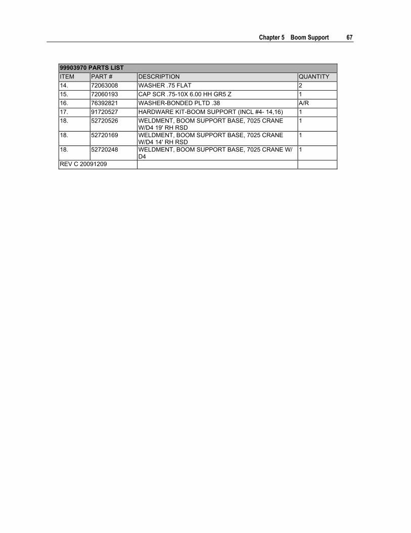
Chapter 5 Boom Support 67
99903970 PARTS LIST ITEM PART # DESCRIPTION QUANTITY 14. 72063008 WASHER .75 FLAT 2 15. 72060193 CAP SCR .75-10X 6.00 HH GR5 Z 1 16. 76392821 WASHER-BONDED PLTD .38 A/R 17. 91720527 HARDWARE KIT-BOOM SUPPORT (INCL #4- 14,16) 1 18. 52720526 WELDMENT, BOOM SUPPORT BASE, 7025 CRANE
W/D4 19' RH RSD 1
18. 52720169 WELDMENT, BOOM SUPPORT BASE, 7025 CRANE W/D4 14' RH RSD
1
18. 52720248 WELDMENT, BOOM SUPPORT BASE, 7025 CRANE W/ D4
1
REV C 20091209


69
In This Chapter Outrigger Installation (99904082)................................................................. 70 Outrigger Hydraulic Installation (99904110)................................................. 75 Outrigger Hydraulic Schematic (99904110) ................................................. 77 Cylinder Assembly, Right Side Power Out (99904714) (Eff 12-1-09) .......... 78 Cylinder Assembly, Right Side Power Out (99904083) (Thru 11-30-09) ..... 79 Cylinder, Right Side Power Out (71713630) (Eff. 12-1-09) .......................... 80 Cylinder, Right Side Power Out (71412571) (Thru 11-30-09) ...................... 81 Cylinder, Left Side Power Out (99904715) (Eff. 12-1-09) ............................ 83 Cylinder Assembly, Left Side Power Out (99904084) .................................. 85 Cylinder, Left Side Power Out (71413626) (Eff. 12-1-09) ............................ 86 Cylinder, Left Side Power Out (71412588) (Thru 11-30-09) ........................ 87 Cylinder, Power Down (71412308) .............................................................. 89 Valvebank, Power Out (73734280) (Eff. 12-1-09) ........................................ 91 Valvebank, Power Out (73734083) .............................................................. 93 Valvebank, Power Down (73734281) (Eff. 12-1-09)..................................... 94 Valvebank, Power Down (73734084) (Thru 11-30-09)................................. 96 Hydraulic Schematic (99903980-1) .............................................................. 98
C H A P T E R 6
Outriggers

70 Dominator IV Parts & Specifications Manual Part # 99904108
Outrigger Installation (99904082)
A
37
37
1
13
10
31
38
38
27
39
2634
3536
1428
15
28
16
DETAIL A24 (6 PLACES)
19 (6 PLACES)
39 (4 PLACES)

Chapter 6 Outriggers 71
99904082-2 DRAWING
B
C
D
31
31
34
2626
34
31
31
38
38 27
2
13
39 17
DETAIL B
DETAIL C
DETAIL D
21,23
22,23
19,24(6 PLCS)
31 (2 PLCS)
37 (2 PLCS)
39 (4 PLCS)
72 Dominator IV Parts & Specifications Manual Part # 99904108
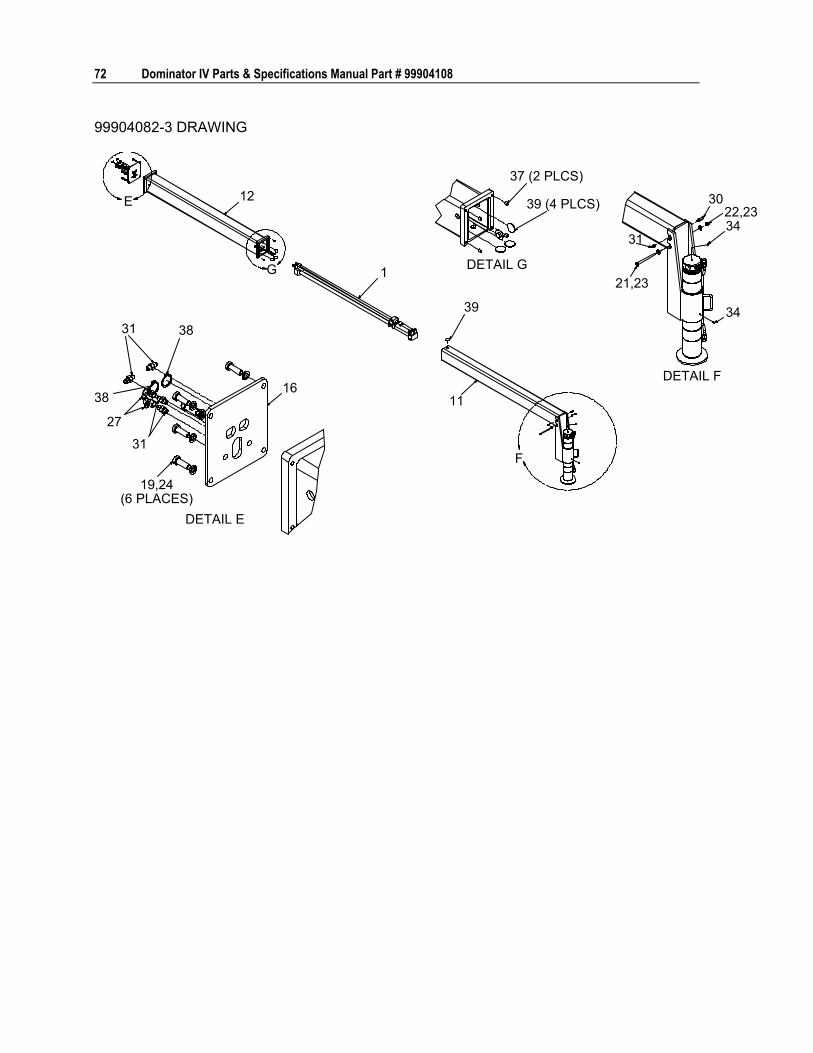
99904082-3 DRAWING
E
F
G
12
1
11
39 34
34
30
31
31 38
38
27
31
16
DETAIL E
19,24(6 PLACES)
21,23
DETAIL F
22,23
37 (2 PLCS)
39 (4 PLCS)
DETAIL G

Chapter 6 Outriggers 73
VALVE BANK LOCATION IN CRANE BOX
28
32
18
8
7
20,25(4 PLCS)
99904082 PARTS LIST ITEM PART # DESCRIPTION KIT # QUANTITY 1. 99904714 DRAWING-RH POWER OUT CYL ASY (WAS
99904083 THRU 11-30-09) REF
2. 99904715 DRAWING-LH POWER OUT CYL ASY (WAS 99904084 THRU 11-30-09)
REF
3. 51720582 HARDWARE KIT-OUTRIGGER (INCL 17-24) REF 4. 51720724 HARDWARE KIT-OUTRIGGER LOCKRINGS REF 5. 91720584 HYDRAULIC KIT-OUTRIGGERS, D4 14' (INCL
25-29) REF
6. 91720585 HYDRAULIC KIT-OUTRIGGERS, D4 19' (INCL 25-29)
REF
7. 73734280 VALVE BANK-3 SECTION POWER DOWN 1 8. 73734281 VALVE BANK-3 SECTION POWER OUT 1 9. 52720460 WLDMT-OUTRIGGER SLIDE OUT DOM4 LH 1 10. 52720461 WLDMT-OUTRIGGER SLIDE OUT DOM4 RR 1 11. 52720470 WLDMT-OUTRIGGER SLIDE OUT DOM4 RR 1 12. 52720558 WELDMENT-OR ARM SUPPORT FRONT 1 13. 52720463 WLDMT-OUTRIGGER ARM SUPPORT 1 14. 71412308 CYLINDER-3.5 BORE 3 15. 5P288970 PORT TUBE .5 OD X 20.67 LG 3 16. 60130300 PLATE-OTR LH CYL MNT D4 2

74 Dominator IV Parts & Specifications Manual Part # 99904108
99904082 PARTS LIST ITEM PART # DESCRIPTION KIT # QUANTITY 17. 60130708 PLATE-OTR RH REAR CYL MNT D4 1 18. 71413868 TUBE ASM-HYD 0.50 OD X 17.19 1 19. 72060093 CAP SCR .50-13X 1.50 HH GR5 Z #3 18 20. 72060923 CAP SCR .38-16X 3.75 HH GR5 Z #3 4 21. 72060103 CAP SCR .50-13X6 HHGR5Z #3 3 22. 72062080 NUT .50-13 HEX NYLOCK #3 3 23. 72063005 WASHER .50 FLAT #3 6 24. 72063053 WASHER .50 LOBK #3 18 25. 72063051 WASHER .38 LOCK #3 4 26. 72053758 ELBOW-M STR/90/M JIC 4 4 #5 OR 6 6 27. 72532690 ELBOW-M JIC/F JIC SW 4 4 #5 OR 6 6 28. 72053763 ELBOW-M STR/90/M JIC 8 8 #5 OR 6 7 29. 72532358 ADPTR-M STR/M JIC 8 8 #5 OR 6 5 30. 72534477 ADPTR-M STR/M JIC 4 4 XLG #5 OR 6 3 31. 72532351 ADPTR-M STR/M JIC 4 4 #5 OR 6 15 32. 72532360 ADPTR-M STR/M JIC 4 4 #5 OR 6 1 33. 72532355 ADPTR-M STR/M JIC 6 6 #5 OR 6 12 34. 72601851 SET SCREW .38-16 X .50 SH SS #4 6 35. 71411152 RETAINING RING-EXT 4.5 STD #4 3 36. 71411151 RING-LOCK DOMINATOR O/R #4 3 37. 72034479 PLUG-PLASTIC #3 8 38. 72661670 RETAINING RING-EXT 1.19 HD 6 39. 60125478 WEAR PAD-ROUND 2.00 15 REV. B 20100111
Chapter 6 Outriggers 75
Outrigger Hydraulic Installation (99904110)
VIEW FROM REAR OF VALVES IN CRANE BOXCRANEPRESSURE
FROMPUMP
FRONTALL "B" PORTS TO
CYLINDER PISTONENDS (EXTEND)
ALL "A" PORTS TOCYLINDER ROD
ENDS (RETRACT)
A3 A2 A1T
PBPB3 B2 B1
8
A3 A2 A1T
PBPB3 B2 B18
CRANE RETURN34 13
1614
TO TANK
LEFT REARRIGHT REAR
RIGHT FRONTLEFT REARRIGHT REAR
RIGHT FRONT
POWEROUT
POWERDOWNFRONT
VIEW FROM FRONT OF VALVES IN CRANE BOX
SEE 99903766 FORHOSES TO CRANE,PUMP, TANK
7
817
14
3412
9
13 (12)
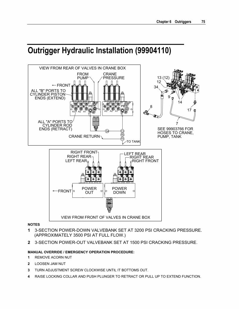
NOTES 1 3-SECTION POWER-DOWN VALVEBANK SET AT 3200 PSI CRACKING PRESSURE.
(APPROXIMATELY 3500 PSI AT FULL FLOW.)
2 3-SECTION POWER-OUT VALVEBANK SET AT 1500 PSI CRACKING PRESSURE. MANUAL OVERRIDE / EMERGENCY OPERATION PROCEDURE: 1 REMOVE ACORN NUT
2 LOOSEN JAM NUT
3 TURN ADJUSTMENT SCREW CLOCKWISE UNTIL IT BOTTOMS OUT.
4 RAISE LOCKING COLLAR AND PUSH PLUNGER TO RETRACT OR PULL UP TO EXTEND FUNCTION.

76 Dominator IV Parts & Specifications Manual Part # 99904108
5 RELEASE PLUNGER AND LOCKING COLLAR ON ANY ACTIVATED VALVE.
6 PUSH AND RELEASE PLUNGER TO RETURN LOCKING COLLAR TO NEUTRAL POSITION.
7 RETURN ADJUSTMENT SCREW TO ORIGINAL POSITION.
8 TIGHTEN JAM NUT.
9 REINSTALL ACORN NUT. 99904110 PARTS LIST ITEM PART # DESCRIPTION KIT # QUANTITY 1. 91720584 HYDRAULIC KIT- DOM IV (II) OUTRIGGER 14' REF 2. 91720585 HYDRAULIC KIT- DOM IV (II) OUTRIGGER 19' REF 3. 73734280 VALVE BANK- 3 SECT DOM O/R POWER
DOWN (WAS 73734083 THRU 11-30-09) 1
4. 73734281 VALVE BANK- 3 SECT DOM O/R POWER OUT (WAS 73734084 THRU 11-30-09)
1
5. 99904715 DWG-D4 OUTRG LH PWR OUT CYL ASY 1 6. 99904714 DWG-D4 OUTRG RH PWR OUT CYL ASY 2 7. 71413868 TUBE ASM-HYD 0.50 O.D X 17.19 1 8. 72532695 TEE-MALE JIC 1.06-12 .75 TUBE #1 or 2 1 9. 72053763 ELBOW-M STR/90/M JIC 8 8 #1 or 2 7 10. 72532690 ELBOW-M JIC/90/F JIC SW 4 4 #1 or 2 16 11. 72053758 ELBOW-M STR/90/M JIC 4 4 (WAS 6) #1 or 2 3 12. 72532364 ADPTR-M STR/M JIC 8 12 #1 or 2 1 13. 72532355 ADPTR-M STR/M JIC 6 6 #1 or 2 12 14. 72532358 ADPTR-M STR/M JIC 8 8 #1 or 2 3 15. 72532351 ADPTR-M STR/M JIC 4 4 #1 or 2 15 16. 72534477 ADPTR-M STR/M JIC 4 4 XLG #1 or 2 3 17. 72532360 ADPTR-M STR/M JIC 12 8 #1 or 2 1 18. 72533567 ELBOW-MSTR/MJUIC XLC 4 4 #1 or 2 3 19. 51396973 HOSE-FJ .50 X 13.5 OAL (8-8) 100R17 #1 or 2 2 20. 51396974 HOSE-FJ .75 X 18.00 OAL (12-12) 100R17 #1 or 2 2 21. 51396975 HOSE-FJ .25 X 13 OAL (4-4) 100R17 #1 or 2 2 22. 51397252 HOSE-FJ .25 X 53 OAL (4-6) 100R17 #1 or 2 1 23. 51397253 HOSE-FZ .25 X 53.00 OAL (4-6) 100R17 #1 or 2 1 24. 51397254 HOSE-FJ .25 X 43.00 (4-6) 100R17 #1 or 2 1 25. 51397255 HOSE-FZ .25 X 43.00 (4-6) 100R17 #1 or 2 1 26. 51397256 HOSE-FJ .25 X 92.00 (4-6) 100R17 #1 or 2 1 27. 51397257 HOSE-FJ .25 X 92.00 (4-6) 100R17 #1 or 2 1 28. 51397258 HOSE-FJ .25 X 104.00 (4-6) 100R17 #1 or 2 1 29. 51397259 HOSE-FZ .25 X 104.00 (4-6) 100R17 #1 or 2 1 30. 51397260 HOSE-FJ .25 X 204.00 (4-6) 100R17 #1 2 31. 51397261 HOSE-FZ .25 X 204.00 (4-6) 100R17 #1 2 32. 51397262 HOSE-FJ .25 X 264.00 (4-6) 100R17 #2 2 33. 51397263 HOSE-FZ .25 X 264.00 (4-6) 100R17 #2 2 34. 51714157 HOSE-FZ .75 X 25.00 (12-12) 100R2 #1 or 2 1 REV D 20101215

Chapter 6 Outriggers 77
Outrigger Hydraulic Schematic (99904110)
RIGHTREAR
LEFTREAR
RIGHTFRONT
EXTENDPORT
10RETRACT
PORT
1010 10
ENDVIEW
15 15
11 18
15 15
19 19
26
22
28
END VIEWEXTENDPORT
10RETRACT10
10 1015 15
30 for 14'32 for 19'
30 for 14'32 for 19'
31 for 14'33 for 19'
31 for 14'33 for 19'
10
1118
10 1516
20 20
27
23
29
25
24
22
RETRACTPORT
1010
10ENDVIEW
15 15
EXTENDPORT10
18
1121 21

78 Dominator IV Parts & Specifications Manual Part # 99904108
Cylinder Assembly, Right Side Power Out (99904714) (Eff 12-1-09)
22
1
3
4
7,8,9
5,6
99904714 PARTS LIST ITEM PART # DESCRIPTION QUANTITY 1. 71413630 CYLINDER-1.2/.7 56.50S 78.31CC C 1 2. 51722477 TUBE ASSEMBLY-POWER OUT OUTRIGGERS 2 3. 71413633 BLOCK-SPACER OUTRG CYL TRANSFER 1 4. 60134727 BRACKET-DOM IV OUTRIGGER 1 5. 72063051 WASHER .38 LOCK 2 6. 72060044 CAP SCREW .38-16X .75 HH GR5 Z 2 7. 72063001 WASHER .25 FLAT 8 8. 72060010 CAP SCREW .25-20X 2.50 HH GR5 Z 4 9. 72062104 NUT .25-20 HEX NYLOCK 4 NEW 20100111

Chapter 6 Outriggers 79
Cylinder Assembly, Right Side Power Out (99904083) (Thru 11-30-09)
11
3
2
6,9
6,9
5,7,8
99904083 PARTS LIST ITEM PART # DESCRIPTION QUANTITY 1. 51720564 TUBE ASY-HYD OTR D4 2 2. 71412571 CYL-1.2/.7 56.50S 78.31CC C 1 3. 71412600 BLOCK-SPACER OUTRG CYL TRANSFER 1 4. 51720581 HARDWARE KIT-P/O OUTRG CYL ASY (INCL 5-
9) 1
5. 72060010 CAP SCR .25-20 2.50 HH GR5Z 4 6. 72060797 CAP SCR .50-13X 2.50 SH PLAIN 4 7. 72062104 NUT .25-20 HEX NYLOCK 4 8. 72063001 WASHER .25 FLAT 8 9. 72063053 WASHER .50 LOCK 4 REV. A 20061206

80 Dominator IV Parts & Specifications Manual Part # 99904108
Cylinder, Right Side Power Out (71713630) (Eff. 12-1-09)
A
A 2
17416 128 10 11
13
14 159
37 7
78.31" CLOSED - 134.25" OPEN - 56.5" STROKE
70.5"SECTION A-A
14" 56.5"
NOTES: 1 TO REDUCE DOWNTIME, REPLACE ALL COMPONENTS OF THE SEAL KIT WHENEVER THE CYLINDER IS
DISASSEMBLED.
2 APPLY NEVER-SEEZ LUBRICATING COMPOUND TO THREADS ON THE CYLINDER HEAD ONLY. KEEP AWAY FROM ALL SEALS.
3 APPLY LUBRIPLATE 630-2 MEDIUM HEAVY, MULTI-PURPOSE LUBRICANT TO ALL SEALS ON PISTON, HEAD GLAND, AND HOLDING VALVE; AND APPLY TO NYLON LOCK RING, CAST IRON PISTON RINGS, AND ROD STINGER THREADS. 71413630 CYLINDER DATA EXTENDED 1.77 IN², 0.14 GAL VOLUME RETRACTED 0.98 IN², 0.08 GAL VOLUME CASE 1.88" BORE X ø1.50" X 21.38" LONG ROD ø 1" X 30.94" LONG DRY WEIGHT 24.37 LB TEST PRESSURE 5500 PSI OPERATING PRESSURE 4200 PSI PORTS SAE #4 O-RING BOSS (7/16-20 UNF-2B) CYLINDER TUBE BURST PRESSURE 20,000 PSI TORQUE TORQUE LOCKNUT (#7) WITH THREADLOCK
COMPOUND TO 35-40 FT-LB
71413630 PARTS LIST ITEM PART # DESCRIPTION KIT # QUANTITY 1. 94396955 SEAL-KIT EXT O/R CYL 1 2. 52722500 ROD ASM- .75 DIA X 75.76 LG 1.63 S 1 3. 71412593 HEAD-1.25 BORE X .75 ROD 1 4. 71412592 PISTON-1.25 BORE X .75 ROD X 1.63 STG 1 5. 52722501 CASE ASM-1.25 BORE X 67.82 LG 1 7. 60134706 STOP TUBE .75 ROD X 14.00 LONG 1 8. 73054218 VALVE-CHECK PILOT/OPEN NONVENT 100PSI 1 9. 76396941 SEAL-ROD .75ID X .187CS DEEP Z-TYPE #1 1 10. 76396950 WEAR RING-PISTON 1.25OD X .38W X .125CS #1 1 11. 76396954 SEAL-PISTON BACKER 1.25 OD X 1.00 ID #1 1 12. 7Q072014 O RING .50X .62X .06 70 #1 1

Chapter 6 Outriggers 81
71413630 PARTS LIST ITEM PART # DESCRIPTION KIT # QUANTITY 13. 7Q072214 O RING 1.00X 1.25X .12 70 #1 1 14. 7Q10P214 BACK-UP RING 1 BORE 1.25 O.D. 0.049 THK #1 1 15. 7R14P007 ROD WIPER TYPE D .75 ROD #1 1 16. 72062108 NUT .50-20 HEX CENTER LOCKING GR8 Z 1 17. 72066029 RETAINING RING-INT 1.31 STD 1 NEW 20100108

82 Dominator IV Parts & Specifications Manual Part # 99904108
Cylinder, Right Side Power Out (71412571) (Thru 11-30-09)
A
A 2 3
8657 139 111214 15
1610
4
78.31" CLOSED - 134.25" OPEN56.5" STROKE
SECTION A-ASCALE 1:1
6" 56.5"
RE
NOTES: 1 TO REDUCE DOWNTIME, REPLACE ALL COMPONENTS OF THE SEAL KIT WHENEVER THE CYLINDER IS
DISASSEMBLED.
2 APPLY NEVER-SEEZ LUBRICATING COMPOUND TO THREADS ON THE CYLINDER HEAD ONLY. KEEP AWAY FROM ALL SEALS.
3 APPLY LUBRIPLATE 630-2 MEDIUM HEAVY, MULTI-PURPOSE LUBRICANT TO ALL SEALS ON PISTON, HEAD GLAND, AND HOLDING VALVE; AND APPLY TO NYLON LOCK RING, CAST IRON PISTON RINGS, AND ROD STINGER THREADS. 71412571 CYLINDER DATA EXTENDED 1.23 IN², 0.24 GAL VOLUME RETRACTED 0.79 IN², 0.15 GAL VOLUME CASE 1.63" BORE X ø1.25" X 67.82" LONG ROD ø 0.750" X 30.94" LONG DRY WEIGHT 33.14 LB TEST PRESSURE 3000 PSI OPERATING PRESSURE 2500 PSI PORTS SAE #4 O-RING BOSS (7/16-20 UNF-2B) CYLINDER TUBE BURST PRESSURE 20,000 PSI TORQUE TORQUE LOCKNUT (#7) WITH THREADLOCK
COMPOUND TO 35-40 FT-LB
71412571 PARTS LIST ITEM PART # DESCRIPTION QUANTITY 1. 94396955 SEAL-KIT EXT O/R CYL (INCL 10-16) 1 2. 52720424 CASE ASM-1.25 BORE X 67.82 LG 1 3. 52720425 ROD ASM- .75 DIA X 75.76 LG 1.63 S 1 4. 71412593 HEAD-1.25 BORE X .75 ROD 1 5. 71412592 PISTON-1.25 BORE X .75 ROD X 1.63 STG 1 6. 60130375 STOP TUBE .75 ROD X 6.00 LONG 1 7. 72062108 NUT .50-20 HEX CENTER LOCKING GR8 Z 1 8. 72066029 RETAINING RING-INT 1.31 STD 1 9. 73054218 VALVE-CHECK PILOT/OPEN NONVENT 100PSI 1

Chapter 6 Outriggers 83
71412571 PARTS LIST ITEM PART # DESCRIPTION QUANTITY 10. 76396941 SEAL-ROD .75ID X .187CS DEEP Z-TYPE 1 11. 76396950 WEAR RING-PISTON 1.25OD X .38W X .125CS 1 12. 76396954 SEAL-PISTON BACKER 1.25 OD X 1.00 ID 1 13. 7Q072014 O RING .50X .62X .06 70 1 14. 7Q072214 O RING 1.00X 1.25X .12 70 1 15. 7Q10P214 BACK-UP RING 1 BORE 1.25 O.D. 0.049 THK 1 16. 7R14P007 ROD WIPER TYPE D .75 ROD 1 NEW 20061011

84 Dominator IV Parts & Specifications Manual Part # 99904108
Cylinder, Left Side Power Out (99904715) (Eff. 12-1-09)
1
1111
4
3
7,8,95,6
99904715 PARTS LIST ITEM PART # DESCRIPTION QUANTITY 1. 71413626 CYLINDER-1.2/.7 44.50S 78.31CC C 1 3. 60134727 BRACKET-DOM IV OUTRIGGER 1 4. 71413633 BLOCK-SPACER OUTRG CYL TRANSFER 1 5. 72063051 WASHER .38 LOCK 2 6. 72060044 CAP SCREW .38-16X .75 HH GR5 Z 2 7. 72063001 WASHER .25 FLAT 8 8. 72060010 CAP SCREW .25-20X 2.50 HH GR5 Z 4 9. 72062104 NUT .25-20 HEX NYLOCK 4 11. 51722724 TUBE ASSEMBLY-POWER OUT OUTRIGGERS 2 NEW 20100111

Chapter 6 Outriggers 85
Cylinder Assembly, Left Side Power Out (99904084)
1
1
2
3
7,8
5,8
6,9
6,9
99904084 PARTS LIST ITEM PART # DESCRIPTION QUANTITY 1. 51720564 TUBE ASY-HYD OTR D4 2 2. 71412588 CYL-1.2/.7 44.50S 78.31CC C 1 3. 71412600 BLOCK-SPACER OUTRG CYL TRANSFER 1 4. 51720581 HARDWARE KIT-P/O OUTRG CYL ASY (INCL 5-
9) 1
5. 72060010 CAP SCR .25-20 2.50 HH GR5Z 4 6. 72060797 CAP SCR .50-13X 2.50 SH PLAIN 4 7. 72062104 NUT .25-20 HEX NYLOCK 4 8. 72063001 WASHER .25 FLAT 8 9. 72063053 WASHER .50 LOCK 4 REV. A 20061206

86 Dominator IV Parts & Specifications Manual Part # 99904108
Cylinder, Left Side Power Out (71413626) (Eff. 12-1-09)
A
A2
19318 128 11 13
149 15
16
20
78.31" CLOSED - 122.88" OPEN - 44.50" STROKE
70.53"44.50"
SECTION A-A4 10
NOTES: 1 TO REDUCE DOWNTIME, REPLACE ALL COMPONENTS OF THE SEAL KIT WHENEVER THE CYLINDER IS
DISASSEMBLED.
2 APPLY NEVER-SEEZ LUBRICATING COMPOUND TO THREADS ON THE CYLINDER HEAD ONLY. KEEP AWAY FROM ALL SEALS.
3 APPLY LUBRIPLATE 630-2 MEDIUM HEAVY, MULTI-PURPOSE LUBRICANT TO ALL SEALS ON PISTON, HEAD GLAND, AND HOLDING VALVE; AND APPLY TO NYLON LOCK RING, CAST IRON PISTON RINGS, AND ROD STINGER THREADS.
71413626 CYLINDER DATA EXTENDED 1.23 IN², 0.24 GAL RETRACTED 0.79 IN², 0.15 GAL CASE 1.63 x 1.25 x 67.82" ROD 0.75 x 30.94" DRY WEIGHT 33.14 LB TEST PRESSURE 3000 PSI OPERATING PRESSURE 2500 PSI PORTS SAE #4 O-RING BOSS (7/16-20 UNF-2B) CYLINDER CASE BURST PRESSURE 20,000 PSI TORQUES LOCKING NUT (#7) 35-40 FT-LB 71413626 PARTS LIST ITEM PART # DESCRIPTION KIT # QUANTITY 1. 94396955 SEAL-KIT EXT O/R CYL 1 2. 52722500 ROD ASM- .75 DIA X 75.76 LG 1.63 S 1 3. 71412593 HEAD-1.25 BORE X .75 ROD 1 4. 71412592 PISTON-1.25 BORE X .75 ROD X 1.63 STG 1 5. 52722501 CASE ASM-1.25 BORE X 67.82 LG 1 8. 73054218 VALVE-CHECK PILOT/OPEN NONVENT 100PSI 1 9. 76396941 SEAL-ROD .75ID X .187CS DEEP Z-TYPE #1 1 10. 76396950 WEAR RING-PISTON 1.25OD X .38W X .125CS #1 1 11. 76396954 SEAL-PISTON BACKER 1.25 OD X 1.00 ID #1 1 12. 7Q072014 O RING .50X .62X .06 70 #1 1 13. 7Q072214 O RING 1.00X 1.25X .12 70 #1 1 14. 7Q10P214 BACK-UP RING 1 BORE 1.25 O.D. 0.049 THK #1 1

Chapter 6 Outriggers 87
71413626 PARTS LIST ITEM PART # DESCRIPTION KIT # QUANTITY 15. 7R14P007 ROD WIPER TYPE D .75 ROD #1 1 16. 70034060 TIES-PLASTIC .18W 8.00L BLACK 1 18. 72062108 NUT .50-20 HEX CENTER LOCKING GR8 Z 1 19. 72066029 RETAINING RING-INT 1.31 STD 1 20. 60134710 STOP TUBE .75 ROD X 26.00 LONG 1 NEW 20100108

88 Dominator IV Parts & Specifications Manual Part # 99904108
Cylinder, Left Side Power Out (71412588) (Thru 11-30-09)
A
A2 3
8457 139
111214 15
10 16
17
SECTION A-ASCALE 1:1
78.31" CLOSED - 122.88" OPEN - 44.5" STROKE
6(3 PLCS)
NOTES: 1 TO REDUCE DOWNTIME, REPLACE ALL COMPONENTS OF THE SEAL KIT WHENEVER THE CYLINDER IS
DISASSEMBLED.
2 APPLY NEVER-SEEZ LUBRICATING COMPOUND TO THREADS ON THE CYLINDER HEAD ONLY. KEEP AWAY FROM ALL SEALS.
3 APPLY LUBRIPLATE 630-2 MEDIUM HEAVY, MULTI-PURPOSE LUBRICANT TO ALL SEALS ON PISTON, HEAD GLAND, AND HOLDING VALVE; AND APPLY TO NYLON LOCK RING, CAST IRON PISTON RINGS, AND ROD STINGER THREADS.
71412588 CYLINDER DATA EXTENDED 1.23 IN², 0.24 GAL RETRACTED 0.79 IN², 0.15 GAL CASE 1.63 x 1.25 x 67.82" ROD 0.75 x 30.94" DRY WEIGHT 33.14 LB TEST PRESSURE 3000 PSI OPERATING PRESSURE 2500 PSI PORTS SAE #4 O-RING BOSS (7/16-20 UNF-2B) CYLINDER CASE BURST PRESSURE 20,000 PSI TORQUES LOCKING NUT (#7) 35-40 FT-LB 71412588 PARTS LIST ITEM PART # DESCRIPTION QUANTITY 1. 94396955 SEAL KIT (INCL 10-16) 1 2. 52720424 CASE ASSEMBLY 1 3. 52720425 ROD ASSEMBLY 1 4. 71412593 HEAD 1 5. 71412592 PISTON 1 6. 60130375 STOP TUBE 3 7. 72062108 NUT .50-20 HEX CENTER LOCKING GR8 Z 1 8. 72066029 RETAINING RING 1 9. 73054218 VALVE-CHECK PILOT/OPEN NONVENT 100PSI 1 10. 76396941 ROD SEAL 1 11. 76396950 PISTON WEAR RING 1

Chapter 6 Outriggers 89
71412588 PARTS LIST ITEM PART # DESCRIPTION QUANTITY 12. 76396954 SEAL-PISTON BACKER 1 13. 7Q072014 O RING .50X .62X .06 70 1 14. 7Q072214 O RING 1.00X 1.25X .12 70 1 15. 7Q10P214 BACK-UP RING 1 BORE 1.25 O.D. 0.049 THK 1 16. 7R14P007 ROD WIPER 1 17. 70034060 TIES-PLASTIC 1 REV. C 20060927

90 Dominator IV Parts & Specifications Manual Part # 99904108
Cylinder, Power Down (71412308)
18" ± 0.06" (STROKE)
28.38" ± 0.12" RETRACT - 46.38" EXTEND
87
218
1410
4 9 1
6
5 31113
1715
1912
16
SAE #8 O-RING BOSS(3/4-16 UNF-2B)
.375-16 UNC-2B(3/4" FULL THREAD)
ø7.5"
SAE #8 O-RING BOSS(3/4-16 UNF-2B)
SAE #4 O-RING BOSS(7/16-20 UNF)
NOTES: 1 TO REDUCE DOWNTIME, REPLACE ALL COMPONENTS OF THE SEAL KIT WHENEVER THE CYLINDER IS
DISASSEMBLED.
2 APPLY NEVER-SEEZ LUBRICATING COMPOUND TO THREADS ON THE CYLINDER HEAD ONLY. KEEP AWAY FROM ALL SEALS.
3 APPLY LUBRIPLATE 630-2 MEDIUM HEAVY, MULTI-PURPOSE LUBRICANT TO ALL SEALS ON PISTON, HEAD GLAND, AND HOLDING VALVE; AND APPLY TO NYLON LOCK RING, CAST IRON PISTON RINGS, AND ROD STINGER THREADS. 71412308 CYLINDER DATA EXTENDED 9.62 IN², 0.75 GAL RETRACTED 4.71 IN², 0.37 GAL CASE 3.50 BORE X ø4.50" ROD ø2.50" DRY WEIGHT 93.1 LB TEST PRESSURE 3500 PSI OPERATING PRESSURE 3000 PSI PORTS SAE #4 O-RING BOSS (7/16-20 UNF-2B) (QUANTITY 2)
SAE #8 O-RING BOSS (3/4-16 UNF-2B) (QUANTITY 2) CYLINDER CASE BURST PRESSURE 19,380 PSI TORQUES •USING LOCTITE GRADE 271 OR EQUIVALENT, TORQUE
LOCKING NUT (#5) 500-550 FT-LB WITH THREADLOCK COMPOUND. •USING LOCKTITE GRADE 243 OR EQUIVALENT, TORQUE O-RING BOSS PLUG (#6) TO 10-12 FT-LB WITH THREADLOCK COMPOUND. •TORQUE HEAD GLAND (#3) TO 250-300 FT-LB. •TORQUE CHECK VALVE (#8) TO 30-35 FT-LB.

Chapter 6 Outriggers 91
71412308 PARTS LIST ITEM PART # DESCRIPTION QUANTITY 1. 71412309 CASE WLDMT-LIFT CYL 1 2. 71411930 ROD WLDMT-EXT O/R CYL 1 3. 71411931 HEAD GLAND-EXT O/R CYL 1 4. 71411932 PISTON-EXT O/R CYL 1 5. -REF- 1.25-12 UNF LOCKNUT 1 6. -REF- SAE NO. 4 STEEL HOL. HEX PLUG 2 7. 94396793 SEAL KIT 1 8. 73054218 VALVE-CHECK PILOT/OPEN NONVENT 100PSI 2 REV. A 20061011

92 Dominator IV Parts & Specifications Manual Part # 99904108
Valvebank, Power Out (73734280) (Eff. 12-1-09)
3
4
7
68
56
8
7
6
TORQUETO 90 FT-LB
TORQUETO 25 FT-LB
TORQUETO 3 FT-LB
1,2(2) 1,2(2) 1,2(2)
73734280 PARTS LIST ITEM PART # DESCRIPTION QUANTITY 1. 73540377 VALVE-SOLENOID DOM IV (INCLUDES COILS) 3 2. 77040498 COIL-12V LEAD WIRE 6 3. 73540269 VALVE-RELIEF 3200 PSI 1 4. 73540270 VALVE-SOLENOID SOFT SHIFT 1 5. 77040499 COIL-12V 36W LEADWIRE 1 6. 72534559 PLUG-STR SOC HD STL 2 ZERO LEAK 3 7. 72534560 PLUG-STR SOC HD STL 4 ZERO LEAK 3 8. 72534561 PLUG-STR SOC HD STL 6 ZERO LEAK 2 NEW 20100108

Chapter 6 Outriggers 93
Valvebank, Power Out (73734083)
WP CONNECTORWP CONNECTOR
15 17 1914 16 18
71110
1 6
5,89
2,4
3,12
NOTE: PUSH BUTTONOVERRIDES THE 4W3P
VALVE TO THISPOSITION:
A B
P TA1 B1 A2 B2 A3 B3
P
PB
3200 PSI2 1
3A 3B 3C
4T
HYDRAULIC SCHEMATIC NOTES: 1 PORTS A1, A2, A3, B1, B2 AND B3 ARE #6 SAE.
2 PORTS P, PB, AND T ARE #8 SAE.
3 RELIEF VALVE 1 IS SET AT 3200 PSI. 73734083 PARTS LIST ITEM PART # DESCRIPTION QUANTITY 1. 73540183 RELIEF VALVE 3200 PSI 1 2. 73540184 2W N.O. POPPET VALVE 1 3. 73540185 4W39 SPOOL VALVE 3 4. 77040477 12 VDC COIL 1 5. 72534430 ORFICE PLUG, Ø.078 1 6. . MANIFOLD 1 7. . 7 mm EXPANDER PLUG 3 8. . #4 SAE PLUG 1 9. . #6 SAE PLUG 2 10. . NAME PLATE 1

94 Dominator IV Parts & Specifications Manual Part # 99904108
73734083 PARTS LIST ITEM PART # DESCRIPTION QUANTITY 11. . #10 SAE PLUG 1 12. 77040476 12 VDC COIL 6 13. . . . 14. . WIRE MARKER, 1 1 15. . WIRE MARKER, 2 1 16. . WIRE MARKER, 3 1 17. . WIRE MARKER, 4 1 18. . WIRE MARKER, 5 1 19. . WIRE MARKER, 6 1 . #6 SAE PLASTIC PLUG 6 . #8 SAE PLASTIC PLUG 3 REV. A 20061011

Chapter 6 Outriggers 95
Valvebank, Power Down (73734281) (Eff. 12-1-09)
4
5
6
645 4
3
4 7
7TORQUETO 25 FT-LB
TORQUETO 3 FT-LB
1,2(2) 1,2(2) 1,2(2)
73734281 PARTS LIST ITEM PART # DESCRIPTION QUANTITY 1. 73540377 VALVE-SOLENOID DOM IV (INCLUDES COILS) 3 2. 77040498 COIL-12V LEAD WIRE 6 3. 73540384 VALVE-RELIEF 1500 PSI 1 4. 72534559 PLUG-STR SOC HD STL 2 ZERO LEAK 3 5. 72534560 PLUG-STR SOC HD STL 4 ZERO LEAK 3 6. 72534561 PLUG-STR SOC HD STL 6 ZERO LEAK 2 7. 72534562 PLUG-STR SOC HD STL 8 ZERO LEAK 2 NEW 20100108

96 Dominator IV Parts & Specifications Manual Part # 99904108
Valvebank, Power Down (73734084) (Thru 11-30-09)
NOTE: PUSH BUTTONOVERRIDES THE 4W3P
VALVE TO THISPOSITION:
A B
P TA1 B1 A2 B2 A3 B3
P
PB
2 1
3A 3B 3C
4T
HYDRAULIC SCHEMATIC
WP CONNECTOR15 17 19
14 16 18
11 10 2
5,8
9
7
1 6
113,12
NOTES: 1 PORTS A1, A2, A3, B1, B2 AND B3 ARE #6 SAE.
2 PORTS P, PB, AND T ARE #8 SAE. 73734084 PARTS LIST ITEM PART # DESCRIPTION QUANTITY 1. . CAVITY PLUG 1 2. . #8 SAE PLUG 1 3. 73540184 4W39 SPOOL VAVLE 3 4. . . . 5. 72534430 ORFICE PLUG, Ø.078 1 6. . MANIFOLD 1 7. . 7 mm EXPANDER PLUG 3

Chapter 6 Outriggers 97
73734084 PARTS LIST ITEM PART # DESCRIPTION QUANTITY 8. . #4 SAE PLUG 1 9. . #6 SAE PLUG 2 10. . NAME PLATE 1 11. . #10 SAE PLUG 1 12. 77040476 12 VDC COIL 6 13. . . . 14. . WIRE MARKER, 1 1 15. . WIRE MARKER, 2 1 16. . WIRE MARKER, 3 1 17. . WIRE MARKER, 4 1 18. . WIRE MARKER, 5 1 19. . WIRE MARKER, 6 1 . #6 SAE PLASTIC PLUG 6 . #8 SAE PLASTIC PLUG 3
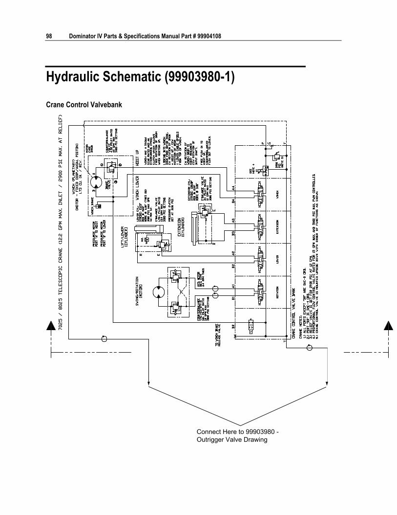
98 Dominator IV Parts & Specifications Manual Part # 99904108
Hydraulic Schematic (99903980-1)
Crane Control Valvebank
Connect Here to 99903980 -Outrigger Valve Drawing

Chapter 6 Outriggers 99
Outrigger Control Valvebank
Connect here to 99903980 -Crane Control Valvebank Drawing


101
In This Chapter Electrical Installation (99904088) (Eff. 9-5-06) ...........................102 Electrical Panel (99903974) .......................................................105 Chassis Electrical Installation (99904034) (Eff. 9-1-06) .............107 Light Installation (99903687) ......................................................111 By-Pass Procedure for Reverse Activated Floodlights...............112 Electrical Outlet (51711674).......................................................112 Light Reel Kits ............................................................................113
C H A P T E R 7
Electrical Options & Installation

102 Dominator IV Parts & Specifications Manual Part # 99904108
Electrical Installation (99904088) (Eff. 9-5-06)
1
277,8,926242425
16,17,18
7,8,27
15
6
12,13,1411 4
28
2,3,4,5
29
NOTES (SEE REFERENCE NUMBER IN BOX):
1 LICENSE PLATE KIT 51715985. TERMINATE WITH 77044690, 77045887 AND 70394069. GROUND EYELET FROM HARNESS ATTACHES TO ONE OF THE SCREWS.
2 CHASSIS GROUND AND BODY GROUND EYELETS FROM LIGHTING HARNESS SHOULD BE ATTACHED TO CHASSIS AND BODY, RESPECTIVELY. USE HARDWARE ITEMS #23, 24, 25, AND 26. DRILL AS NEEDED.
3 USE HEATSHRINK 77045926 TO PROTECT UNUSED COMPARTMENT LIGHT CONNECTOR.

Chapter 7 Electrical Options & Installation 103
HARNESS 77441185REAR OF BODYTAILLIGHTS, MARKERLIGHTS, ETC.
HARNESS 77441133 (ONE PER SIDEPACK)FLOOD LIGHTS, COMPARTMENT LIGHTS
HARNESS AS PART OF CONTROL PANELCHASSIS, CRANE, OUTRIGGER, LIGHT CONTROLS
VIEW OF BODY SHOWN WITHOUT DOORS OR SIDEPACK TOPS
NOTES (SEE REFERENCE NUMBER IN BOX):
4 EXTENSION HARNESS TO FRONT MARKER LIGHT AND FLOODLIGHTS. ONE PER SIDE
5 9' HARNESS - 77441125
6 11' HARNESS - 77441126
7 13', 14' HARNESS - 77441127
8 19' HARNESS - 77441202 99904088 PARTS LIST ITEM PART # DESCRIPTION QUANTITY 1. 51720172 ELECTRICAL PANEL (DOM4) 1 1. 51719191 ELECTRICAL PANEL (DOM1 & DOM2) 1 2. 72063050 WASHER .31 LOCK 4 3. 72060021 CAP SCR .31-18X .50 HH GR5 Z 4 4. 89396626 EDGING-PLASTIC BLK A/R 5. 77040484 GROMMET-2IN DIA LED MARKER 2 6. 77040483 LIGHT-3-BAR LED 1 7. 72063000 WASHER .19 W FLAT ANSI B27.2Z 5 8. 72062106 NUT 10-24 HEX NYLOCK 4 9. 77441004 LIGHT-LICENSE PLATE 1 10. 60130829 MTG BRACKET-WIRE HARNESS (DOM IV) 2 11. 60120705 MTG BRKT-WIRE HARNESS (DOM I AND II) 2 12. 72060025 CAP SCR .31-18X 1.00 HH GR5 Z 6

104 Dominator IV Parts & Specifications Manual Part # 99904108
99904088 PARTS LIST ITEM PART # DESCRIPTION QUANTITY 13. 72063002 WASHER .31 FLAT 6 14. 72062109 NUT .31-18 HEX NYLOCK 6 15. 77040020 ALARM-BACK UP HORN 1 16. 72060005 CAP SCR .25-20X 1.25 HH GR5 Z (WAS
72060002) 2
17. 72063001 WASHER .25 FLAT 2 18. 72062104 NUT .25-20 HEX NYLOCK 2 19. 72060047 CAP SCR .38-16X 1.25 HH GR5 Z 2 20. 72063003 WASHER .38 W FLAT ANSI B27.2Z 2 21. 72063051 WASHER .38 LOCK ZINC 2 22. 72062103 NUT .38-16 HEX NYLOC ZINC 2 23. 77040481 GROMMET-FOR LED S/T/T D(I) 6 24. 77040493 LIGHT-STOP/TURN/TAIL LED 4in DIA (WAS
77040432) 4
25. 77040180 LIGHT-BACKUP 2 26. 76392275 GROMMET-TAIL LIGHT 6 27. 72060636 SCR-MACH #10-24X .75 RDH PH ZINC 4 28. 77040570 LIGHT-CLEARANCE RED LED OVAL
W/GROMMET 2
29. 77040569 LIGHT-CLEARANCE AMBER LED OVAL W/GROMMET
2
REV. E 20101217

Chapter 7 Electrical Options & Installation 105
Electrical Panel (99903974)
4
1
1213
14
915
16
W5W6
W3W4
W1W2
87
3
BACK VIEW
FRONT VIEW
CJ-909CJ-910CJ-911
M1
CJ-912CJ-913
CJ-914
NOTPOLARITYSENSITIVE
TETHERCONNECTIONFOR RADIOREMOTE
CJ-905CJ-906CJ-907CJ-908
CJ-901CJ-902
CJ-903CJ-904
CONNECTIONSFROM HARNESS (#10)
10,115,6

106 Dominator IV Parts & Specifications Manual Part # 99904108
99903974 PARTS LIST ITEM PART # DESCRIPTION QUANTITY 1. 60251214 PANEL-ELECTRICAL CONTROL DOM IV 1 2. 70034061 TIES-PLASTIC .18W 12.00L BLACK 10 3. 70396891 DECAL-ELECTRICAL CONTROL PANEL 1 4. 70733496 METER-HOUR DATCON PUSH LOCK
MOUNTING 3
5. 72060612 SCR-MACH # 8-32X .75 RDH 4 6. 72063181 WASHER-SS 10 WRT TYPE 304 4 7. 76394572 GROMMET-2 X 6 OVAL CMPT LIGHT 1 8. 77040509 LIGHT-COMPARTMENT LED (WAS 77040384) 1 9. 77041500 SWITCH-ROCKER BODY 8 10. 77041502 SWITCH-ROCKER MTG PANEL END 4 11. 77041504 SWITCH-ROCKER MTG PANEL MIDDLE 4 12. 77041687 SWITCH-ROCKER BODY MOMENTARY 6 13. 77041688 SWITCH-ROCKER ACTUATOR 6 14. 77041689 SWITCH-ROCKER SINGLE MOUNTING PANEL 6 15. 77044779 SWITCH-ROCKER GREEN ACTUATOR 8 16. 77441200 HARNESS (DOM IV) 1 REV A 20071003

107
Chassis Electrical Installation (99904034) (Eff. 9-1-06)
1
16
14
19
20
EXTRA HARDWARE AND BRACKET (#51)ARE SUPPLIED FOR MOUNTING ASNECESSARY. THE RECOMMENDEDORIENTATION OF COMPONENTS IS SHOWN.
IF THE WIRE BETWEEN THEPOWER MODULE (#5) AND THEBATTERY IS LONGER THAN 24"INSTALL PARTS #19 AND #20IN-LINE, AS CLOSE TO THEBATTERY AS POSSIBLE.
5,6,7,8,9
2,3,4
12,13,1512,13,15
4,11
USE HEAT SHRINK(#45) OVER THESECONNECTIONS.
LEFT POST:PASS THROUGH(FUSED)
RIGHT POST:SWITCHEDTHROUGH RELAY(FUSED)
99904034 PARTS LIST ITEM PART # DESCRIPTION QUANTITY 1. 60128133 BRACKET-EFM 1 2. 72060003 CAP SCR .25-20X .88 HH GR5 Z 4 3. 72063001 WASHER .25 FLAT 4 4. 72062104 NUT .25-20 HEX NYLOCK 6 5. 77040490 RELAY-12 VOLT POWER RELAY MODULE 2 6. 77041712 FUSE-FMX 30 AMP PINK 1 7. 77041713 FUSE-FMX 40 AMP GREEN 1 8. 77041711 FUSE-FMX 20 AMP BLUE 1 9. 77041714 FUSE-FMX 60 AMP YELLOW 1 10. 77040491 CONNECTOR - 2 CAV FEMALE 2 11. 72060654 SCR-MACH .25-20X 2.00 RDH ZINC 2

108 Dominator IV Parts & Specifications Manual Part # 99904108
12. 72062207 NUT 8-32 HEX NYLOCK 3 13. 72063181 WASHER-SS 10 WRT TYPE 304 3 14. 51717388 KIT-EFM (ENGINE FUNCTION MODULE) 1 15. 72060612 SCR-MACH # 8-32X .75 RDH 3 16. 77041251 RELAY-12V 30 AMP NOM/40 AMP MAX 1 17. 77040053 TERM-RING I .25 STUD 12-10 GA 1 18. 77040354 TERM-RING NI .25 STUD 8 WIRE 2 19. 77441116 FUSEHOLDER-HIGH AMP2 BOLT WITH
COVER 1
20. 77441115 FUSE-AMG-125 AMP 1 21. 77040045 TERM-RING NI .31 STUD 6 WIRE 6 22. 77040492 TERM-RING NI .25 STUD 6 WIRE 1 23. 77045948 TERM-FEM MP 16-18 AWG 4 24. 77045949 SEAL-MP RED CABLE SEAL 4 25. 77040137 TERM-FEM SLIP ON12-10/.25 TAB 2 26. 77040186 TERM-FSLPON I .25TAB 16-14 GA 2 27. 51719331 KIT-DIODE DEUTSCH DT SERIES 3 28. 51719332 KIT-SPLICE METRIPACK 6 PIN 4 29. 77044984 WIRE-6 GA GXL RED A/R 30. 77441199 HARNESS DOM CHASSIS DOM4 1 30. 77441130 HARNESS DOM CHASSIS DOM1 & DOM2 1 42. 89044232 WIRE-14GA RED STRD TYPE GPT A/R 43. 89044274 WIRE-14GA BLACK STRD TYPE GPT A/R 44. 89396659 TUBE-HEAT SHRINK .38X 2IN DOUBLE WALL 8 45. 77045926 TUBE-HEAT SHRINK-1.5 INCH DUAL WALL 4FT 0.0833 46. 89393368 TUBE-HEAT SHRNK .25X 6"LG (OBS) 2 48. 77040473 TERM-RING NI .38 STUD 6 WIRE 1 49. 77044651 TERM-RING .38 STUD 16-14 GA 1 50. 89044363 WIRE-12GA WHITE STRD TYPE GPT 4 51. 60025470 ANGLE-AL .12X1.00X1.00X 4.00 1 52. 70034061 TIES-PLASTIC .18W 12.00L BLACK 6 53. 77441110 CABLE POWER RED #6 X 36 1 REV A 20060922

10
9
9990
4034
DRA
WIN
G
3086
8785
3086
8785
3086
87a
85
3086
8785
3086
8785
87a
IGN
ITIO
NP
OW
ER
GR
OU
ND
16
8630 87
85
14
SE
E E
FM M
AN
UA
L
INTE
RLO
CK
PO
WE
RIG
NIT
ION
PO
WE
RB
ATT
ER
Y P
OW
ER
IGN
ITIO
N &
E-B
RA
KE
PO
WE
RE
NG
INE
SP
EE
DE
NG
INE
STO
PE
NG
INE
STA
RT
RE
LAY
#1
RE
LAY
#2
RE
LAY
#3
RE
LAY
#4
E-B
RA
KE
CO
NN
EC
TIO
NS
TO
HA
RN
ES
S #
304SW
ITC
H A
ND
LIG
HT
SU
PP
LIE
DW
ITH
PTO
3227
1
2827
2625
2625
16
CH
AS
SIS
IGN
ITIO
N
1817
1822
28
28
3086
8785 10 23 24
70A
27
28
PO
WE
R/R
ELA
YM
OD
ULE
- #5
PO
WE
R/R
ELA
YM
OD
ULE
- #5
2121
2121
8630 87
85 10 23 24
70A
60A
30A
20A
40A
E-B
RA
KE
(SW
ITC
HS
UP
PLI
ED
AS
PA
RT
OF
CH
AS
SIS
)
21
125A
21
BA
TTE
RY
9990
4034
-AU
TOM
ATI
CSI
NG
LE P
TO (M
UN
CIE
/CH
ELSE
A)
ALL
ISO
N M
D (6
000/
4000
) SER
IES
TRA
NSM
ISSI
ON
TO P
TOG
RO
UN
DS
PLI
CE
TO P
TO A
CTI
VA
TIO
NC
IRC
UIT
12V
IGN
ITIO
N H
OT
NO
T U
SE
D IN
THIS
AP
PLI
CA
TIO
N77
0417
01
6 5 7
3 2 10A
4
3
1 2
NO
TE: 7
7041
701
WIL
L E
NG
AG
E T
HE
PTO
AN
D P
RO
VID
E A
GR
OU
ND
SIG
NA
L TO
THE
IMT
CH
AS
SIS
ELE
CTR
ICA
L W
IRIN
GW
HE
N T
HE
SW
ITC
H IS
AC
TIV
E.
THIS
ALL
OW
S E
NG
INE
STA
RT
TO F
UN
CTI
ON
IFTH
E P
RE
SS
UR
E S
WIT
CH
ON
TH
E P
TOO
PE
NS
(AFT
ER
EN
GIN
E K
ILL
OC
CU
RS
,FO
R E
XA
MP
LE.)


111
Light Installation (99903687)
B
CA
A
3
1
6
7
ADD 1/4" FOR DOM4CRANE BOX
1.38"1.50"
6.0"0.5"0.28"
(QTY 3)
0.5"
OPTIONALLOCATIONS
DETAIL A: DIMENSIONS TYPICALBOTH SIDES -STANDARD(CRANE ROTATOR TO SIDE/FRONT)
DETAIL D: ALT. LOCATIONCRANE SIDE ONLY(CRANE ROTATOR TO REAR)
0.5"0.5"
9.25"
ALL COMPARTMENTSEXCEPT CRANE BOX
DETAIL COPTIONALLOCATIONS
4.63" 4.75"
0.28" (3)
SEE DETAILSA & D
4,5
2HARDWAREINCLUDED
TERMINATE WIRESWITH #8, 9, 10.NOT POLARITYSENSITIVE.
DETAIL B
99903687 PARTS LIST ITEM PART # DESCRIPTION 51719944 51719193 51719194 51720234 51719195 9-FOOT
COMPT. LIGHTS
11-FOOT COMPT. LIGHTS
13 & 14-FOOT COMPT. LIGHTS
19-FOOT COMPT. LIGHTS
FLOODLIGHT KIT (2 LIGHTS)
1. 60117375 BRACKET-FLOODLIGHT 12V REAR SP
2 2 2 2
2. 77040424 FLOODLIGHT-COMPOSITE WORK LAMP
2 2 2 2 2
3. 72601846 CAP SCR-SS .25-20X 1.25 HH 4 4 4 4 4 4. 72063183 WASHER-SS .25 W MS811 FLAT
18-8 4 4 4 4 4
5. 72062194 NUT-SS .25-20 NYLOC 4 4 4 4 4 6. 77040384 LIGHT-COMPARTMENT 12V
2.1AMP 5 7 9 11
7. 72617558 SCR-SELF TAP-SS #10X .50 HH SLOT
10 14 18 22
8. 77044574 CONN-2 CAV TOWER 2 2 2 2 2 9. 77045888 TERM-14-16GA FEMALE 4 4 4 4 4 10. 77044927 CABLE SEAL-14 GA GREY 4 4 4 4 4 REV. D 20071218

112 Dominator IV Parts & Specifications Manual Part # 99904108
By-Pass Procedure for Reverse Activated Floodlights A floodlight installed on the rear driver's side of the body will illuminate when the chassis transmission is in reverse.
NOTE:
Some state and local laws prohibit reverse-activated rear-facing floodlights. Consult your local and state regulations regarding reverse-activated, rear-facing floodlights. Disable if necessary.
To disable, remove the relay located behind the crane box switch panel as shown.
Electrical Outlet (51711674) 51711674 PARTS LIST ITEM PART # DESCRIPTION QUANTITY 1. 76393038 GROMMET 1 2. 77040232 TERMINAL-INSULATED SPADE 12-10 GA 3 3. 77044018 CONNECTOR-1/2 STRAIN RELIEF 3/8-1/2 1 4. 77044135 GROUND PLUG 1 5. 77044372 ELECTRICAL BOX 2X44 DEEP WELL 1 6. 77044384 WEATHERPROOF COVER 1 7. 77044501 OUTLET 110V GFI 20A 1 8. 89044039 CABLE 14GA/3WIRE 20FT

Electrical Options & Installation 113
Light Reel Kits LIGHT REEL KIT - 12 VOLT (51707758) LIGHT REEL KIT - 110 VOLT - LIGHT DUTY (51707759) LIGHT REEL KIT - 110 VOLT W/50' CORD (51712724) ITEM PART # DESCRIPTION 12 VOLT
QUANTITY 110 VOLT QUANTITY
110 VOLT QUANTITY W/CORD
1. 77040187 REEL - 50' 1 1 77040368 REEL - 50' 1 2. 77040225 BULB - 12V 1 77040224 BULB - 120V 75W ROUGH SERVICE 1 1 3. 77040049 BUTT CONNECTOR 1 4. 77040000 TERMINAL 1 5. 72060012 CAP SCR 1/4-20X3 HH GR5 1 1 72060025 CAP SCR 5/16-18X1 HH GR5 4 6. 72062104 NUT 1/4-20 LOCK 5 3 72062109 NUT 5/16-18 HEX NYLOC 4 7. 72060002 CAP SCR 1/4-20X3/4 HH GR 5 2 2 8. 89044234 WIRE 14GA YELLOW X 96" 1 9. 89044235 WIRE 14GA WHITE X 12" 1 10. 89044072 WIRE 12GA/3 WIRE X 216" 1 1 11. 72063002 WASHER 5/16 FLAT 8


115
In This Chapter Salvage / Plumbing Installation Kit (99903803) 115 Salvage Tank Installation, Welder in Load Bed (99903807) 118 Salvage Pump Assembly (51721592) (Eff. 6-08) 119 Antifreeze/Salvage/Water Pump (70734343) (Eff. 6-2008) 120 Antifreeze Salvage Pump Assembly (51720270/Dwg. 99904048) (Through 5-2008) 122 Headache Rack Parts & Installation (99903657) 123 Master Lock Installation (99904143) 125 Fuel Fill, Chevy/GMC (99903710) 127
C H A P T E R 8
Miscellaneous Options

116 Dominator IV Parts & Specifications Manual Part # 99904108
Salvage / Plumbing Installation Kit (99903803)
1
4
3
56
15
2
16
12
1314
17
10
7,8,9SELECTFITTINGAS NEEDED
7,8,9SELECTFITTINGAS NEEDED
NOTE: PLUMBINTO LUBRICATED AIR11
99903803 HOLE DETAIL - INSTALLATION OF SALVAGE TANK ON UNITS WITHOUT A WELDER CUTOUT
DETAIL OF HOLE TO BE CUT IN THE FLOORFOR THE SALVAGE TANK. USE THIS LOCATIONONLY IF THERE IS NOT A WELDER CUTOUT.
3.50"14.0"
5.50"
FRONT

Chapter 8 Miscellaneous Options 117
51712838 PARTS LIST (DRAWING 99903803) ITEM PART # DESCRIPTION QUANTITY 1. REF TANK-WLDMT 1 52719967 34 GALLON SALVAGE TANK WELDMENT 52719985 60 GALLON SALVAGE TANK WELDMENT 52720009 TANK-WLDMT, 34 GAL SALVAGE (LOADBED) 52720028 TANK-WLDMT, 60 GAL SALVAGE (LOADBED) 51719983 34 GALLON SALVAGE KIT (W/O WELDER) 51719984 60 GALLON SALVAGE KIT (W/O WELDER) 2. REF PUMP ASM SALVAGE 1 3. 72532681 SIGHT GAUGE- .75 PLUG W/REFLCT 1 4. 72532436 FAST FILL-VENT (ZV10) 1 5. 72531836 REDUCER BUSH-STL 1.25- .75 1 6. 72533054 ELBOW-MPT/45/M JIC .75 12 1 7. 72532976 HOSE FTG-TYPE F 12 .75 PARK A/R 8. 72533378 HOSE FTG-TYPE J 12 .75 PARK A/R 9. 72533445 HOSE FTG-TYPE Z 12 .75 PARK A/R 10. REF FILTER-REGULATOR-LUBRICATOR 1 11. 72531991 TEE-STREET STL .50 1 12. 72533592 NIPPLE-BARB BRS .50MPT/90/.75 (PART OF
FRL) 1
13. 72531830 REDUCER BUSH-STL .50- .25 1 14. 72053459 NIPPLE-BARB BRS .25MPT .25 1 15. 89393634 HOSE-HYD .75 100R4 881-12 PAR A/R 16. 89392146 HOSE-GP .25 X 250 WP GRAY 801-4 A/R 17. 72066452 CLAMP-HOSE .25- .62 SAE 4 SS 2 22. 52719770 HYD RESERVOIR WELDMENT 1 23. 99903748 FLOOR, 11' RR CRANE 1
REV. A 20060307

118 Dominator IV Parts & Specifications Manual Part # 99904108
Salvage Tank Installation, Welder in Load Bed (99903807)
4 HOLES ø 0.41"
10.0"
10.0"
2.92"
SLOT RADIUS 2.50"
24.79"(60 GAL)
15.53"(34 GAL)
4.28"5.00"
37.75"
MOUNTING HOLES AND CUTOUTSFOR INSTALLATION OF SALVAGETANK WITH WELDER IN LOADBED.
NOTE:
See 99903803 for plumbing information.
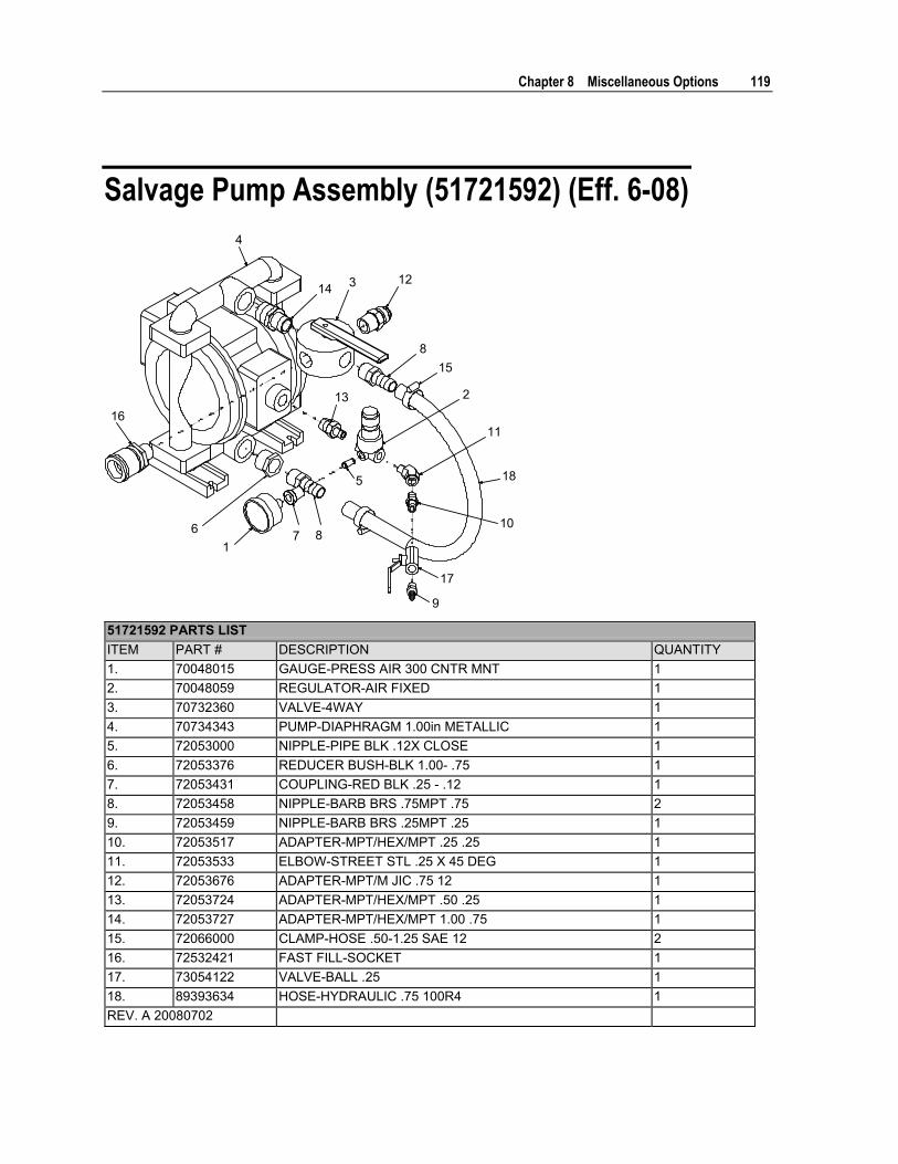
Chapter 8 Miscellaneous Options 119
Salvage Pump Assembly (51721592) (Eff. 6-08)
176 8
5
2
11
17
123
815
16
9
10
4
14
13
18
51721592 PARTS LIST ITEM PART # DESCRIPTION QUANTITY 1. 70048015 GAUGE-PRESS AIR 300 CNTR MNT 1 2. 70048059 REGULATOR-AIR FIXED 1 3. 70732360 VALVE-4WAY 1 4. 70734343 PUMP-DIAPHRAGM 1.00in METALLIC 1 5. 72053000 NIPPLE-PIPE BLK .12X CLOSE 1 6. 72053376 REDUCER BUSH-BLK 1.00- .75 1 7. 72053431 COUPLING-RED BLK .25 - .12 1 8. 72053458 NIPPLE-BARB BRS .75MPT .75 2 9. 72053459 NIPPLE-BARB BRS .25MPT .25 1 10. 72053517 ADAPTER-MPT/HEX/MPT .25 .25 1 11. 72053533 ELBOW-STREET STL .25 X 45 DEG 1 12. 72053676 ADAPTER-MPT/M JIC .75 12 1 13. 72053724 ADAPTER-MPT/HEX/MPT .50 .25 1 14. 72053727 ADAPTER-MPT/HEX/MPT 1.00 .75 1 15. 72066000 CLAMP-HOSE .50-1.25 SAE 12 2 16. 72532421 FAST FILL-SOCKET 1 17. 73054122 VALVE-BALL .25 1 18. 89393634 HOSE-HYDRAULIC .75 100R4 1 REV. A 20080702

120 Dominator IV Parts & Specifications Manual Part # 99904108
Antifreeze/Salvage/Water Pump (70734343) (Eff. 6-2008)

Chapter 8 Miscellaneous Options 121
70734343 PARTS LIST ITEM PART # DESCRIPTION QUANTITY 1. 73734362 AIR VALVE ASSEMBLY (PART OF 30) 1 2. 73734363 CHECK BALL (PART OF 29) 4 3. 73734364 BEARING, SLEEVE 2 4. VALVE, PILOT (PART OF 30) 1 5. INTERMEDIATE 1 6. BUMPER (PART OF 30) 2 7. BUSHING (PART OF 30) 2 8. CAP, AIR INLET ASSEMBLY 1 9. CAPSCREW, 3/8-16 X 1.00 4 10. CAPSCREW, HEX 5/16-18 X 1.00 16 11. CAPSCREW, HEX HD, 5/16-18 X 1 1/4 16 12. CAPSCREW, HEX HD 5/16-18 X 1 3/4 4 13. CHAMBER, OUTER 2 14. 73734365 DIAPHRAGM (PART OF 29) 2 15. 73734366 GASKET, AIR VALVE (PART OF 30) 1 16. 73734367 GASKET, PILOT VALVE (PART OF 30) 1 17. 73734368 GASKET, AIR INLET CAP (PART OF 30) 1 18. MANIFOLD, SUCTION 1 19. MANIFOLD, DISCHARGE 1 20. 73734369 O-RING (PART OF 30) 2 21. PLATE, INNER DIAPHRAGM 2 22. PLATE, OUTER 2 23. ACTUATOR PIN (PART OF 30) 2 24. RING, RETAINER (PART OF 30) 2 25. 73734370 DIAPHRAGM ROD 1 26. 73734371 SEAL, U-CUP (PART OF 30) 2 27. 73734372 SEAT, CHECK BALL (PART OF 29) 4 28. LOCK WASHER, 5/16 16 29. 94744179 FLUID REPAIR KIT (INCL. 2,14,27) REF 30. 94744180 AIR END KIT (INCL. 1,4,6,7,15-17,20,23,24,26) REF

122 Dominator IV Parts & Specifications Manual Part # 99904108
Antifreeze Salvage Pump Assembly (51720270/Dwg. 99904048) (Through 5-2008)
10
26
1
11
78
17
13714
12
20
9
15
163,4,5
51720270 PARTS LIST (DRAWING 99904048) ITEM PART # DESCRIPTION QUANTITY 1. 70732360 VALVE-4WAY 1 2. 70731387 PUMP 1 3. 72060026 CAP SCR .31-18X 1.25 HH GR5 Z 4 4. 72062109 NUT .31-18 HEX NYLOCK 4 5. 72063002 WASHER .31 FLAT 4 6. 72053558 ADPTR-MPT/HEX/MPT .75 .75 1 7. 72053458 NIPPLE-BARB BRS .75MPT .75 2 8. 72066000 CLAMP-HOSE .50-1.25 SAE 12 2 9. 72053676 ADPTR-MPT/M JIC .75 - 12 (WAS 72053671) 1 10. 72053679 ADPTR-MPT/M JIC .75 - 16 1 11. 72053517 ADPTR-MPT/HEX/MPT .25 .25 2 12. 70048147 REGULATOR-AIR 1 13. 72053000 NIPPLE-PIPE BLK .12X CLOSE 1 14. 72053431 COUPLING-RED BLK .25 - .12 1 15. 70048205 GAUGE-PRESS AIR (WAS 70048015) 1 16. 72531412 ELBOW-MPT/90/M JIC .25 4 (WAS
72053533) 1
17. 89393634 HOSE-HYD .75 100R4 881-12 PAR 18" 20. 72053376 REDUCER BUSH-BLK 1.00- .75 1 REV. B 20070523

Chapter 8 Miscellaneous Options 123
Headache Rack Parts & Installation (99903657)
DETAIL ASCALE 3/16:1
2
3
1
4, 54, 5
4, 5, 7
4, 5
6, 7(SEE NOTE #3)
5, 7
4, 5
6, 7(SEENOTE #3)
NOTES: 1 Drill 3/8" diameter holes to fasten headache rack.

124 Dominator IV Parts & Specifications Manual Part # 99904108
2 Item #3, headache rack end, required only with standard compartment. Used on either side.
3 Use bonded washers when attaching to sidepack. 99903657 PARTS LIST ITEM PART # DESCRIPTION QUANTITY 1. N/A BODY-W D2-11' R 1 L STD REF 2. 52718845 HEADACHE RACK BODY-BOLT ON A/R 3. 52718846 HEADACHE RACK END GUSSET-BOLT ON A/R 4. 72060025 CAP SCR.31-18X 1.0 HHGR5Z (WAS
72060026, 72601832) A/R
5. 72063002 WASHER .31 FLAT (WAS 72063184) A/R 6. 76392598 WASHER-BONDED PLTD .31 A/R 7. 72062109 NUT .31-18 HEX NYLOC (WAS 72062167) A/R REF 51718842 HEADACHE RACK, DOMINATOR STANDARD
RIGHT AND STANDARD LEFT
REF 51718843 HEADACHE RACK, DOMINATOR STANDARD LEFT AND RAISED RIGHT
REF 51718844 HEADACHE RACK, DOMINATOR RAISED RIGHT AND LEFT
REV B 20061107
REV. A 20051122

Chapter 8 Miscellaneous Options 125
Master Lock Installation (99904143)
43
5
9187
5
6710655
4
6
11
15
16
116
3
1415
13
13
16
14 11B-BB-B
C-C
A-A
F-F DRILL HOLESIN SIDEPACKTHRU ONEWALL ONLY.
1.19"
2.13"5.26"
1.0"
2.31"ø0.33
ø0.63FOR LH SIDEPACKTHE END IS THESAME.5,6,7,10,11
13,1413,14
AT EACH DOORROD LOCATION
3,4,5,6 3,4,5,6RH FRONT
FF
AA
AA
B
BAA
CC
5,6,7,10,11 3,4,5,63,4,5,6
MASTER LOCK KIT #
BODY DESCRIPTION
51720688 14' DOMINATOR IV RAISED RIGHT FRONT 51720685 14' DOMINATOR IV STANDARD 51720687 19' DOMINATOR IV STANDARD 51720686 19' DOMINATOR IV RAISED RIGHT FRONT KIT # 51720688 51720685 51720686 51720687 ITEM #
PART # DESCRIPTION QUANTITY
1. 52715598 (WAS 60123476, 60130843)
ROD-MASTER LOCK 160" X 6" 1 1
1. 60130846 ROD-MASTER LOCK 110" X 6" 1 1. 60130844 ROD-MASTER LOCK 28" 1 1. 60130845 ROD-MASTER LOCK 83" X 6" 1 1 1. 52720566
(WAS 60130847)
ROD-MASTER LOCK 220" X 6" 1 1
1. 60130848 ROD-MASTER LOCK 88" 1 1. 60130849 ROD-MASTER LOCK 170" X 6" 1
126 Dominator IV Parts & Specifications Manual Part # 99904108
KIT # 51720688 51720685 51720686 51720687 ITEM #
PART # DESCRIPTION QUANTITY
3. 60117216 BRACKET-ROD STOP 7 7 9 9 8. 60117213 BRACKET-PADLOCK 4 4 4 4 10. 60117214 BRACKET-ROD HANGER 3 2 3 2 13. 60117775 SPROCKET 2 2 15. 70144864 SPRING 1 1 16. 70144865 CHAIN-ROLLER #25 STANDARD 15" 15" 17. 51720711 HARDWARE KIT 1 17. 51720712 HARDWARE KIT 1 17. 51720713 HARDWARE KIT 1 17. 51720714 HARDWARE KIT 1 99904143 PARTS LIST ITEM PART # DESCRIPTION QUANTITY 1. VARIOUS ROD-MASTER LOCK XXX" LG X 6" AS REQ'D 2. 3. 60117216 BRACKET-ROD STOP AS REQ'D 4. 72601847 BOLT-CARRIAGE .31-18X1.25 SQNK SS AS REQ'D 5. 72062167 NUT-SS .31-18 HEX NYLOC AS REQ'D 6. 72063152 WASHER-SS .31 R FLAT WRT TYPE 304 AS REQ'D 7. 72601590 CAP SCR-SS .31-18 X 1 TRH PHH AS REQ'D 8. 60117213 BRACKET-PADLOCK MASTER LOCK AS REQ'D 9. 70034277 GROMMET - POLY .52 ID AS REQ'D 10. 60117214 BRACKET-ROD HANGER MASTER LOCK AS REQ'D 11. 70143654 COLLAR-SHAFT AS REQ'D 12. 13. 60117775 SPROCKET-BROWNING AS REQ'D 14. 72060556 SET SCREW .25-20 X .25 AS REQ'D 15. 70144864 SPRING AS REQ'D 16. 70144865 CHAIN-ROLLER #25 STANDARD AS REQ'D 17. VARIOUS HARDWARE KIT (INCL 4-7,9,11,14) AS REQ'D REV. B 20090604

Chapter 8 Miscellaneous Options 127
Fuel Fill, Chevy/GMC (99903710)
2
23
1
FRONT OFCHASSIS
EXISTING CLAMP
EXISTING ELBOW
EXISTING CLAMP
EXISTINGTUBE
99903710 PARTS LIST ITEM PART # DESCRIPTION QUANTITY 1. 70396444 ELBOW, 90 DEG FUEL HOSE 2” (RUBBER) 2 2. 72066062 HOSE CLAMP 4 3. 60128990 TUBE 1
NEW 20051020


129
In This Chapter Welder Deck, 24" Long with 2 Underbody Toolboxes (51720055)...................129 Welder Deck, 35" Long with 2 Underbody Toolboxes (51720057)...................130 Welder Deck, 36" Long with Flat Deck (51720059)..........................................131 Welder Deck, 24" Long with Tall Compartment (51719952) ............................131 Welder Deck, 35" Long with Curbside Tall Compartment (51720061).............133 Welder Deck, 35" Long with Streetside Tall Compartment (51720063) ...........134
Welder Deck, 24" Long with 2 Underbody Toolboxes (51720055)
A
A
1
3
4
65
2
77
SECTION A-ASCALE 0.16:1
51720055 PARTS LIST ITEM PART # DESCRIPTION QUANTITY 1. 52720056 WELDER DECK-WLDMT 35in L UBT-R UBT 1 2. 72661599 LATCH ASM-3PT DOM (II) COMPRESSION 2 3. 60108981 TIE DOWN-BODY 4.00 FRAME 4 4. 60109048 ROD-THREADED .62-11 X 14.00 4 5. 72063007 WASHER .62 FLAT 8 6. 72062091 NUT .62-11 HEX NYLOCK 8 7. 60128412 ROD-DOOR 8.12 LG W/.75" OFFSET 4 NEW 20070302
C H A P T E R 9
Welder Platforms

130 Dominator IV Parts & Specifications Manual Part # 99904108
Welder Deck, 35" Long with 2 Underbody Toolboxes (51720057)
A
A
B
B C
C
1
3
4
65
2
77
VIEW C-CSCALE 0.16:1
VIEW:INSIDEUBTB
SECTION A-ASCALE 0.16:1
51720057 PART LIST ITEM PART # DESCRIPTION QUANTITY 1. 52720058 WELDER DECK-WLDMT 35in L UBT-R UBT 1 2. 72661599 LATCH ASM-3PT DOM (II) COMPRESSION 2 3. 60108981 TIE DOWN-BODY 4.00 FRAME 4 4. 60109048 ROD-THREADED .62-11 X 14.00 4 5. 72063007 WASHER .62 FLAT 8 6. 72062091 NUT .62-11 HEX NYLOCK 8 7. 60128412 ROD-DOOR 8.12 LG W/.75" OFFSET 4 NEW 20070302

Chapter 9 Welder Platforms 131
Welder Deck, 36" Long with Flat Deck (51720059) 51720059 PARTS LIST ITEM PART # DESCRIPTION QUANTITY 1. 77044807 HARNESS-LUBE FRONT MARKER LIGHTS 1 2. 51716399 HARDWARE KIT 1 3. 52720060 WELDER DECK, 36" FLAT 1 4. 60108981 TIE DOWN 4 5. 60109048 THREADED ROD, 0.62-11 X 14 4

132 Dominator IV Parts & Specifications Manual Part # 99904108
Welder Deck, 24" Long with Tall Compartment (51719952)
A
A11 12
18
13
4 5
8
16 17
17 16
FOR CLARITY, COMPARTMENTTOP, FLOOR, DOORSNOT SHOWN
SECTION A-ASCALE 0.12:1
51719952 PARTS LIST ITEM PART # DESCRIPTION QUANTITY REF 52719953 D(II)-WELDER DECK-W D2 24in L RSD-R UBT INCL 4-28 4. 60128310 PANEL WELDER DECK UBTB RF #2 1 5. 60128312 PANEL WELDER DECK UBTB RF #1 1 8. 60128315 CHANNEL-FORM 1.24X 4.00X 50.00 3 11. 60128317 PANEL-WELDERDECK LF 60H #1 1 12. 60128318 PANEL-WELDERDECK LF 60H #2 1 13. 70144288 DOOR STOP-SELF CLOSING SPRING 2 16. 60116990 GUSSET-FRONT PANEL RH BTTM D2 2 17. 60117060 GUSSET-FRONT PANEL LH BTTM D2 2 18. 72661383 HINGE-SS 10GA BUTT W/IMT LOGO OFFSET 4 20. 60129361 BACK-BTM WELDER DECK RF D2 24in 1 21. 60129358 SDPK HEADER WELDER DECK 19.62 2 22. 60129362 CHANNEL-FORM 1.00X 2.00X 23.62 1 23. 60129360 MTG BAR-WLDR DECK 24in W D(II) 2 2 24. 60129357 BACK-BTM WELDER DECK LF D2 24in 1 25. 60129356 TOP WELDER DECK CARGO FLOOR UBTB-
VERT COMPT 24in 1
26. 60129359 TOP-WELDER DECK RSD COMPT D2 24in 1 27. 52719954 DOOR-WLDMT HEM D(II) 18.88H X 20.50W (40 1 28. 52719092 DOOR-WLDMT HEM D(II) 56.88H X 20.50W (40 1 NEW 20070302

Chapter 9 Welder Platforms 133
Welder Deck, 35" Long with Curbside Tall Compartment (51720061)
B
B
C
C
58 3
3
15 4
76
SECTION B-BSCALE 0.12:1SECTION C-C
SCALE 0.12:1 51720061 PARTS LIST ITEM PART # DESCRIPTION QUANTITY 1. 52720062 WELDER DECK-WLDMT 35in L UBTB-R RSD 1 3. 72661599 LATCH ASM-3PT DOM (II) COMPRESSION 2 4. 60109048 ROD-THREADED .62-11 X 14.00 4 5. 60108981 TIE DOWN-BODY 4.00 FRAME 4 6. 72062091 NUT .62-11 HEX NYLOCK 8 7. 72063007 WASHER .62 FLAT 8 8. 60128412 ROD-DOOR 8.12 LG W/.75" OFFSET 2 10. 60130297 ROD-DOOR 27.12 LG W/.75" OFFSET 2 REV. A 20070302

134 Dominator IV Parts & Specifications Manual Part # 99904108
Welder Deck, 35" Long with Streetside Tall Compartment (51720063)
56
1
3 LEFT SIDERIGHT SIDE
ITEM PART # DESCRIPTION QUANTITY 1. 52720064 WELDER DECK-WLDMT 35in L RSD-R UBT 1 3. 72661599 LATCH ASM-3PT DOM (II) COMPRESSION 2 5. 60108981 TIE DOWN-BODY 4.00 FRAME 4 6. 60109048 ROD-THREADED .62-11 X 14.00 4 7. 72062091 NUT .62-11 HEX NYLOCK 8 8. 72063007 WASHER .62 FLAT 8 9. 60128412 ROD-DOOR 8.12 LG W/.75" OFFSET 2 10. 60130297 ROD-DOOR 27.12 LG W/.75" OFFSET 2

135
In This Chapter Decal List....................................................................................135 Dominator and Crane Logo Placement ......................................137 Body Safety Decal Placement....................................................138 Dominator Control Decal Placement ..........................................139 Crane Safety Decal Placement on Dominator Door...................140 Hydraulic Oil Decal Placement...................................................141 Fuel Tank Decal Placement .......................................................142 Air Tank Decal Placement..........................................................143 Outrigger Decal Placement ........................................................144 Reflector & Hitch Decal Placement ............................................145 Compressor Decal Placement....................................................147
C H A P T E R 1 0
Dominator Decal Examples & Placement

136 Dominator IV Parts & Specifications Manual Part # 99904108
Decal List Dominator I, II, IV, and DSC20 have many common and some unique decals. See the chart below and the decal application photos on subsequent pages for application details. ITEM
DECAL PART NUMBER
DESCRIPTION QUANTITY PER BODY
MODEL NOTES
1. 70396637 DOMINATOR DECAL KIT 1 ALL INCLUDES ITEMS 2-8 2. 70396657 DECAL-DOMINATOR
IDENTIFICATION 2 ALL
3. 70392213 DECAL-CAUTION, DON'T WASH/WAX
1 ALL
4. 70392309 DECAL-DIESEL FUEL ONLY 2 ALL FOR DIESEL ENGINES ONLY
5. 70392453 DECAL-UNLEADED GASOLINE ONLY
2 ALL FOR GASOLINE ENGINES ONLY
6. 71393886 DECAL-DANGER EXPLODING TANK 1 ALL 7. 70391601 DECAL-AIR TANK DRAIN 1 ALL 8. 70392982 DECAL-SERVICE & REPAIR 1 ALL 9. 70396635 DECAL-FUSE PANEL LAYOUT 1 DOM I & II 10. 70396600 DECAL-ELECTRICAL PANEL 1 DOM I & II 11. 70396254 DECAL-SWITCH BRACKET 1 DSC20 12. 70396891 DECAL-ELECTRICAL PANEL 1 DOM IV 13. 70396892 DECAL-SWITCH PANEL 1 DOM IV 14. 70398872 MANUAL OPERATION, OUTRIGGER
VALVEBANK (WAS 70396633 PRIOR TO 6-15-07, 70397215 FROM 6-15-07 THRU 11-30-09)
1 DOM I & II
15. 70398873 MANUAL OPERATION, DOM IV OUTRIGGER VALVEBANK (WAS 70396921 THRU 11-30-09)
1 DOM IV
16. 70397063 DECAL-HITCH, RECEIVER 2000V-16000P
1 DOM I & DSC
17. 70397064 DECAL-HITCH, PINTLE 6000V-30000P
1 DOM II & IV
18. 70398983 DECAL-CAUTION, WELDING DAMAGE
1 ALL BY LIGHT BOX ON REAR OF VEHICLE
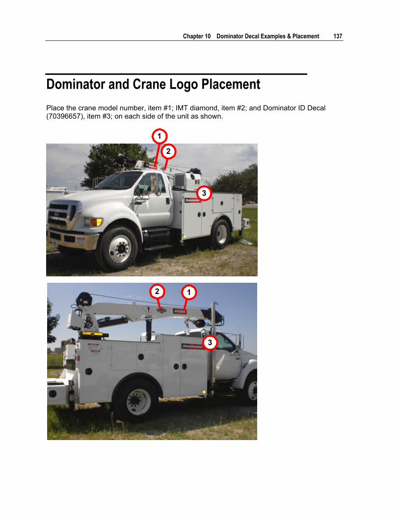
Chapter 10 Dominator Decal Examples & Placement 137
Dominator and Crane Logo Placement Place the crane model number, item #1; IMT diamond, item #2; and Dominator ID Decal (70396657), item #3; on each side of the unit as shown.
1
2
3
3
12

138 Dominator IV Parts & Specifications Manual Part # 99904108
Body Safety Decal Placement
1
1
2
1 2
Both Sides2
Both item #1 - 70394445, and item #2 - 70392868, are applied on all four sides of the carrier vehicle, so the operator can see the dangers regarding electrocution and the crane loadline from any point of crane operation.

Chapter 10 Dominator Decal Examples & Placement 139
Dominator Control Decal Placement
1 23
4
1 70396164 Decal - Danger, Breathing Hazard 2 70396635 Decal - Dominator Fuse Panel 3 70396600 Decal - Dominator Electrical Panel (Dominator I and II)
(Dominator IV uses 70396891 Electrical Panel Decal)
4 70398872 Decal - Manual Operation, Outrigger (Dominator I and II) (Dominator IV uses 70398873)

140 Dominator IV Parts & Specifications Manual Part # 99904108
Crane Safety Decal Placement on Dominator Door

Chapter 10 Dominator Decal Examples & Placement 141
Hydraulic Oil Decal Placement
1
Place 70394189, Decal-Mobil Oil Recommendations, on top of the hydraulic tank and on the right side of the fill cap. Decal must be legible from inside the load bed.

142 Dominator IV Parts & Specifications Manual Part # 99904108
Fuel Tank Decal Placement
Note: If unleaded gas fuel tank, use decal part number 70392453.

Chapter 10 Dominator Decal Examples & Placement 143
Air Tank Decal Placement

144 Dominator IV Parts & Specifications Manual Part # 99904108
Outrigger Decal Placement
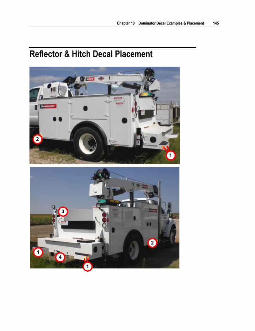
Chapter 10 Dominator Decal Examples & Placement 145
Reflector & Hitch Decal Placement
1
2
2
1
1
3
4

146 Dominator IV Parts & Specifications Manual Part # 99904108
Place four red reflector decals, 70039057, item #1, at the sides and outer edges of the tailgate as shown.
Place two amber reflector decals, 70039058, item #2, at the front of the sidepacks as shown.
Place the welding caution decal, 70398983, item #3, on the side of the light box at the left rear of the body.
Place a hitch decal, item #4, above the hitch on the rear of the body. Typically, Dominator I and DSC use 70397063 - Receiver Hitch, 2000 lb tongue and 16,000 lb gross trailer weight. Typically, Dominator II and IV us 70397064 - Pintle Hitch, 6000 lb tongue and 30,000 lb gross trailer weight.

Chapter 10 Dominator Decal Examples & Placement 147
Compressor Decal Placement The Dominator 2 may be purchased with a CAS435HA or CAS3560 compressor.
Decal placement on a CAS435HA compressor:
Decal placement on a CAS3560 compressor:
Note: All decals for the CAS3560 air compressor are included on decal sheet 95718232. See the CAS3560 manual for complete decal placement information.

148 Dominator IV Parts & Specifications Manual Part # 99904108
FINE THREAD BOLTS (ENGLISH) COARSE THREAD BOLTS (ENGLISH) SIZE BOLT
DIA. GRADE 5
SAE J429GRADE 5
GRADE 8
SAE J429GRADE 8
SIZE BOLT DIA.
GRADE 5
SAE J429GRADE 5
GRADE 8
SAE J429GRADE 8
(DIA-TPI) (INCHES) PLAIN PLATED PLAIN PLATED (DIA-TPI)
(INCHES) PLAIN PLATED PLAIN PLATED
(FT-LB) (FT-LB) (FT-LB) (FT-LB) (FT-LB) (FT-LB) (FT-LB) (FT-LB) 5/16-24 0.3125 19 14 27 20 5/16-18 0.3125 17 13 25 18 3/8-24 0.375 35 26 49 35 3/8-16 0.375 31 23 44 33 7/16-20 0.4375 55 41 78 58 7/16-14 0.4375 49 37 70 52 1/2-20 0.5 90 64 120 90 1/2-13 0.5 75 57 105 80 9/16-18 0.5625 120 90 170 130 9/16-12 0.5625 110 82 155 115 5/8-18 0.625 170 130 240 180 5/8-11 0.625 150 115 220 160 3/4-16 0.75 300 225 420 315 3/4-10 0.75 265 200 375 280 7/8-11 0.875 445 325 670 500 7/8-9 0.875 395 295 605 455 1-12 1 645 485 995 745 1-8 1 590 445 910 680 1 1/8-12 1.125 890 670 1445 1085 1 1/8-7 1.125 795 595 1290 965 1 1/4-12 1.25 1240 930 2010 1510 1 1/4-7 1.25 1120 840 1815 1360 1 3/8-12 1.375 1675 1255 2710 2035 1 3/8-6 1.375 1470 1100 2380 1780 1 1/2-12 1.5 2195 1645 3560 2670 1 1/2-6 1.5 1950 1460 3160 2370 NOTES 1 Tightening torques provided are midrange.
2 Consult bolt manufacturer’s particular specifications, when provided.
3 Use flat washers of equal strength.
4 All torque measurements are given in foot-pounds.
5 Torque values specified are for bolts with residual oils or no special lubricants applied. If special lubricants of high stress ability, such as Never-Seez compound graphite and oil, molybdenum disulphite, collodial copper or white lead are applied, multiply the torque values in the charts by the factor .90. The use of Loctite does not affect the torque values listed above.
WARNING
Anytime a gear-bearing bolt is removed, it must be replaced with a new bolt of the identical grade and size. Once a bolt has been torqued to 75% of its proof load and then removed, the torque coefficient may no longer be the same as when the bolt was new thus giving indeterminate clamp loads after torquing. Failure to replace gear-bearing bolts may result in bolt failure due to metal fatigue causing death or serious injury.
Thread Torque Chart (English)

Chapter 10 Thread Torque Chart (Metric) 149
FINE THREAD TORQUE CHART (METRIC)
COARSE THREAD TORQUE CHART (METRIC)
TIGHTENING TORQUE
TIGHTENING TORQUE
SAE J429GRADE 5
SAE J429GRADE 8
SIZE (DIA-TPI)
BOLT DIA (INCHES)
SAE J429GRADE 5
SAE J429GRADE 8
SIZE (DIA-TPI)
BOLT DIA. (INCHES)
PLAIN (KG-M)
PLATED (KG-M)
PLAIN (KG-M)
PLATED (KG-M)
PLAIN (KG-M)
PLATED (KG-M)
PLAIN (KG-M)
PLATED (KG-M)
5/16-24 0.3125 3 2 4 3 5/16-18 0.3125 2 2 3 2 3/8-24 0.375 5 4 7 5 3/8-16 0.375 4 3 6 5 7/16-20 0.4375 8 6 11 8 7/16-14 0.4375 7 5 10 7 1/2-20 0.5 12 9 17 12 1/2-13 0.5 10 8 15 11 9/16-18 0.5625 17 12 24 18 9/16-12 0.5625 15 11 21 16 5/8-18 0.625 24 18 33 25 5/8-11 0.625 21 16 30 22 3/4-16 0.75 41 31 58 44 3/4-10 0.75 37 28 52 39 7/8-11 0.875 62 45 93 69 7/8-9 0.875 55 41 84 63 1-12 1 89 67 138 103 1-8 1 82 62 126 94 1 1/8-12 1.125 123 93 200 150 1 1/8-7 1.125 110 82 178 133 1 1/4-12 1.25 171 129 278 209 1 1/4-7 1.25 155 116 251 188 1 3/8-12 1.375 232 174 375 281 1 3/8-6 1.375 203 152 329 246 1 1/2-12 1.5 304 228 492 369 1 1/2-6 1.5 270 210 438 328 NOTES 1 Tightening torques provided are midrange.
2 Consult bolt manufacturer’s particular specifications, when provided.
3 Use flat washers of equal strength.
4 All torque measurements are given in kilogram-meters.
5 Torque values specified are for bolts with residual oils or no special lubricants applied. If special lubricants of high stress ability, such as Never-Seez compound graphite and oil, molybdenum disulphite, collodial copper or white lead are applied, multiply the torque values in the charts by the factor .90. The use of Loctite does not affect the torque values listed above.
WARNING
Anytime a gear-bearing bolt is removed, it must be replaced with a new bolt of the identical grade and size. Once a bolt has been torqued to 75% of its proof load and then removed, the torque coefficient may no longer be the same as when the bolt was new thus giving indeterminate clamp loads after torquing. Failure to replace gear-bearing bolts may result in bolt failure due to metal fatigue causing death or serious injury.
Thread Torque Chart (Metric)