manual rabbit stunner: with integrated recorder
TRANSCRIPT

MANUAL RABBIT STUNNER: WITH INTEGRATED RECORDER MODEL: ATM-002-R
USER’S GUIDE Rev.2.3

USER’S GUIDE MANUAL RABBIT STUNNER MOD. ATM‐002‐R
2
PRESENTATION INTRODUCTION Dear customer, Congratulations on having purchased a MANUAL RABBIT STUNNER WITH INTEGRATED RECORDER and on having placed your trust in NOVA MEVIR S.L. You have the best rabbit feet cutting machine. It’s the result of research, excellent design and years of experience. You can be sure you will be completely satisfied with the machine performance. However, you must carefully follow a few simple rules for use and maintenance. We hope the machine more than meets your slaughterhouse requirements. NOVA MEVIR S.L.

USER’S GUIDE MANUAL RABBIT STUNNER MOD. ATM‐002‐R
3
INDEX
1. TECHNICAL DATA SHEET 4
2. GENERAL INSTRUCTIONS 5
2.1 INSTALLATION AND CONNECTION 5
2.2 MACHINE FUNCTIONING 7
2.3 OPTIONAL OPERATING (FOOD SUPPORT) 10
2.4 CONTROL 11 2.4.1 MAIN SCREEN 11 2.4.2 CONFIGURATION 15 2.4.3 STUNNER CONFIGURATION 17 2.4.4 USB FILES CONFIGURATION 21 2.4.5 SERVER CONFIGURATION 22 2.4.6 LANGUAGE CONFIGURATION 24 2.4.7 RECORDS AND SAVING OF FILES 24 2.4.8 RECORDS AND SENDING TO SERVER 27 2.4.9 PRODUCTION STATISTICS 29
2.5 FILES 30
2.6 SERVER 33
2.7 REMOTE CONTROL 34
2.8 USB CONNEXION 36
2.9 MANDATORY SAFETY GLOVES CHARACTERISTICS 37
2.10 CLEANING AND MAINTENANCE 38
3. SPARE PARTS 39
4. SAFETY, WARNINGS AND CALIBRATION 40

USER’S GUIDE MANUAL RABBIT STUNNER MOD. ATM‐002‐R
4
1. TECHNICAL DATA SHEET
Manual Rabbit Stunner Production max: 300 rabbits/h The machine is compliant with EC regulations Nº1099/2009 An electronic panel with a digital voltage and amperage screen, anesthesia adjustment, 0‐200 V (optional version 0‐400V), power on light. Transformer with separate windings. Standard electrodes, interchangeable with our ATM and AT stunner models. Possibility of purchasing an adjustable base (photo). The clamp electrodes only activate upon pressing a safety button, which is very important to prevent workplace accidents. Correct stunning confirmation light.
Electro‐polished stainless steel machine. Weight : 10 kg – Weight of adjustable base: 10 kg. (*) Pursuant to EC regulations, as of January 2013, all new slaughterhouses must comply with the following (annex II of Regulation 1099/2009): Stunning equipment must be equipped with a system that records the stunning settings and these records must be kept for one year. It eners into effect for all other slaughterhouses as of December 2019

USER’S GUIDE MANUAL RABBIT STUNNER MOD. ATM‐002‐R
5
2. GENERAL INSTRUCTIONS
2.1 INSTALLATION AND CONNECTION
The installation of the machine in your work place will be carried out by operators of Nova Mevir S.L., or by specialized personnel authorized by Nova Mevir S.L. Once the machine has been removed from the transport box ( ready to move it with forklift to the place chosen for installation provided it has the regulating foot that is OPTIONAL), it will proceed to its ideal positioning according to the manipulation of the animal prior to its hanging. We attached next, the measurements and images of the height adjustment in a simple way, of the support to support the stunner. Thanks to its versatility we can achieve very ergonomic and customized measures according to the operator’s height and needs.
There is also the possibility of fixing the Machine to the ground with the supports below, although it is not a mandatory or fundamental operation for the proper functioning of the stunning system.
Working height fixing screw
Ground fixing support
Stainless Steel screw type “TACO REIDO” (4 units)

USER’S GUIDE MANUAL RABBIT STUNNER MOD. ATM‐002‐R
6
Later we will move on to place the electrical cabinet / recorder. It is recommended to place this element in a clean area (out of reach of the cleaning hoses) and at a sufficient height to access the controls and also protected from the water. The connection to the mono‐phase electric network (50/60Hz), will be carried out by means of the terminals (PHASE + NEUTRAL + EARTH), the equipment is prepared to operate between 0 and 240 V (take into account that the output voltage will be directly proportional to that of the input with a correction factor of 1.66). Last, only remains the cabinet with the stunner, which is done with a 5 meter long cable (standard and customizable measure if required by the client) where the communication and power passes.
Next we will enumerate and describe the connectors (harting type) that the cabinet has, we will use the connectors depending on the type of stunner we have:
0‐240V AC 50/60Hz I phase+Neutral+Earth
Connection 1 POWER (5 PINS): AT‐004 fix tray ‐> unique cable AT‐004 mobile tray‐>power cable ATP‐002 grill‐> power cable ATM‐002 hand‐> unique cable
Connection 2 MANEUVER (5 PINS): AT‐004 mobile tray‐>maneuver cable ATP‐002 grill‐> maneuver cable
Connection 3 OPTIONAL BEACON (4 PINS)
INTERCONNECTING CABLE

USER’S GUIDE MANUAL RABBIT STUNNER MOD. ATM‐002‐R
7
2.2 MACHINE FUNCTIONING This machine is intended to stun the rabbit before hanging and slaughtering one by one and manually, as indicated by European regulations for animal welfare. The stunning process consists of circulating a current through the head of the rabbit for a certain period of time in such a way that the rabbit is stunned. To achieve this, a voltage is applied between the terminals which generates sufficient current. The machine indicates in various ways whether the stunning has been correct or incorrect, depending on whether the current and time are within the configured settings. The machine allows to adjust, according to the customer's needs and preferences, the voltage, the minimum and maximum current, the minimum and maximum time. The numbers (x) used below refer to the images shown at the end of the chapter. Once it has been checked that there are no personnel or objects not related to the production, we will switch on the power of the main switch (1) located on the electrical cabinet door (wait a few seconds until the PLC program is loaded), if everything is correct, the white light of the pilot (2) will come on and the main screen will appear. The first time we connect the machine, we must follow a few simple steps to configure it according to our model and needs, which will be saved for the future. To do this we must consult the chapter Stunner configuration where the concepts of correct and incorrect stunning are also explained. Before starting to produce with the machine, it must be verified that the operator uses safety insulating gloves (such as those in attached image, up to 500 V AC protection), and foot wear with the same characteristics (electrical insulators). Once the basic safety standards described above have been met (very important due to energy involved in the process) we will proceed to use the use of the machine. First we will select the volts for the stunning using the potentiometer (3); our choice will be reflected on the PLC screen (4) in the voltage column, for a maximum input voltage of 240 V (208 V) there will produce up to 400 V (350 V) output, indicate that with output voltages between 200 and 250 V the result is very satisfactory.

USER’S GUIDE MANUAL RABBIT STUNNER MOD. ATM‐002‐R
8
Now we will explain how to use the machine manual stunner model ATM‐002‐R, and how to manipulate the animal correctly for an optimum stunned: pick up the rabbit by the loin with one hand and the stunner with the other hand ( as if it were a gun), support the rabbit on a table or horizontal surface and introduce the forehead (as indicated in the image) of the animal against the skewers / electrodes, then press the button as a trigger (7) to enable the voltage circuit (this safety measure is applied so that an involuntary friction of the operator with the operator with the electrodes does NOT cause an accidental discharge)..
The SATISFACTORY stunned process (god stunning) it will be confirm with the green pilot (5) in the electrical panel (and the green light of the beacon of optional form (5.1)). And it can be temporally consult in the screen (4). The NON‐SATISFACTORY stunned process (bad stunning) will turn on the red light (6) and the sound (and the red light of the beacon optional form (6.1) and the sound (6.2)), and don’t’ be necessary to rearm it. Only when the values exceed the maximum time and the maximum intensity, and make the thermal differentials jump, will the red light button be reset by pressing it (the differentials will have been reset beforehand).
Contact zone for the spikes/electrodes Attached is a
information sheet for safety gloves

USER’S GUIDE MANUAL RABBIT STUNNER MOD. ATM‐002‐R
9
(6) Red pilot –Bad stunned
(4)Monitor ‐ PLC
(3) Potentiometer ‐ voltage
(1) General selector
(5) Green pilot – Good stunned
(2)White pilot ‐ tension
(7) Button (trigger) security
(6.1) Red pilot – Bad stunned (optional beacon)
(5.1) Green pilot – Good stunned (optional beacon)
(6.2) Sound warning – Bad stunned (optional beacon)

USER’S GUIDE MANUAL RABBIT STUNNER MOD. ATM‐002‐R
10
2.3 OPTIONAL OPERATING (FOOD SUPPORT) With the acquisition of the support foot (optional), there is a variant of operation, which can be useful sporadically and in particular. The hand stunner is positioned as indicated in the following image:
Then the rabbit is placed in a table, place some laterals limits (green color) as indicated in the sketch to limit the movements of the animal. Then, taking the rabbit by ears with one hand, it slides towards the electrodes, while with other hand we press the safety button (trigger) (7). This is an operation that mimics our AT‐004 stunner, designed for higher production, but it can be a more economical way to simulate geometries and methodology of a superior model. For this mode, the same safety guidelines and actions must be followed (insulating gloves, insulating boots, etc.) as in standard operation.
Side guides (limits)

USER’S GUIDE MANUAL RABBIT STUNNER MOD. ATM‐002‐R
11
2.4 CONTROL According to the EC, from January 2013 the new slaughterhouses must respect the following (Annex II of the regulation 1099/2099): “The material of the stunner must be equipped with the stunned parameters of the register that must be conserved for a year”. With the purpose to adapt the new regulation, this model has the function of visualization, catchment register and sending the data. For this purpose, it has a controller with a touch screen to display and perform all operations. Each of the different screens available is described below.
2.4.1 MAIN SCREEN
This is the normal work screen. From here you can access the rest of the available screens. The central area shows the real‐time measurements of voltage (volts), current (milliamps) and stunning time (milliseconds). At the beginning of the stunning process, the voltage will be a constant value, the intensity will increase its value and the time will increase until the end of the stunning process, which will be when the operator stops applying the terminals to the rabbit.

USER’S GUIDE MANUAL RABBIT STUNNER MOD. ATM‐002‐R
12
Each stun is stored in a record with the measurements obtained in its execution. The lower part shows the measurements taken in the last stun, N: the record number and <‐‐> indicates the time between the last 2 stuns and the average time between all stuns (times longer than 10 seconds are not displayed or used). While stunning is in progress and the configured stun parameters are met, this is indicated by the green pilot/light in the cabinet and by the following green stripe on the display.
If a stun is completed and the set parameters are not met, this is indicated by the red pilot/light in the cabinet, an audible warning if enabled, and the following red stripe on the display.

USER’S GUIDE MANUAL RABBIT STUNNER MOD. ATM‐002‐R
13
The measurements of each stunning in progress are moved to the lower part of the screen at the end of the stun, which is the last record made. The following additional information is displayed on the screen:
Indicates that the electrodes are under voltage. In AT No Micro mode it is always on.
Indicates that the push button on the pistol or the detector is activated. There is a separate indication for each of them.
Indicates the stunner mode selected in the configuration.
Indicates the version of the stunner program.
In the event that the emergency button is pressed or the electrical safety protections of the control panel are triggered, the machine will cease to be operational and the following messages will appear to signal this, which will disappear automatically when the incident is restored.
At the top there is an icon that allows us to see the status of the USB stick.
This is the normal working state. Indicates that the USB memory is connected and ready for use. When a USB memory stick is connected, this mark will appear automatically.
Indicates activity on the USB memory, data is being recorded.
Indicates that the USB flash drive is not connected or is ready to be safely disconnected. Very important, no data will be recorded in this state.

USER’S GUIDE MANUAL RABBIT STUNNER MOD. ATM‐002‐R
14
To safely remove the USB stick, click on the green notch and a dialogue box will appear. If we accept, we will be able to remove it safely. If we click on the red mark, the following will appear.
Important, once the extraction has been accepted, to reactivate it, you must physically disconnect the USB memory stick and reconnect it. Only if the server mode is activated, there is an icon at the top that allows you to see the status of the server.
This is the normal working state. Indicates that sending data to the server is enabled and that the last connection to the server was successful.
Indicates that data is being sent to the server.
Indicates that sending data to the server is enabled and that the last connection to the server failed.
Indicates that the connection to the server is Paused. Records are still being saved, but not sent to the server.
The following buttons give access to the rest of the screens.
Configuration
List of records and recording of files.
Production statistics
Indicates that data is being sent to the server.

USER’S GUIDE MANUAL RABBIT STUNNER MOD. ATM‐002‐R
15
2.4.2 CONFIGURATION
The following options are available:
Stunner configuration.
USB files configuration.
Sendings to server configuration.
Language selection.
Manufacturer configuration.(restricted access with special code).
In order to access each option, you will be asked to enter the code shown below, once entered, it will remain active until 1 minute has passed without interacting with the screen:

USER’S GUIDE MANUAL RABBIT STUNNER MOD. ATM‐002‐R
16
Most screens have navigation buttons at the top with the following functionality:
Go back to the main screen.
Go back to previous screen.
MEVIR86

USER’S GUIDE MANUAL RABBIT STUNNER MOD. ATM‐002‐R
17
2.4.3 STUNNER CONFIGURATION
This chapter is one of the most important chapters in order to use the machine correctly. The configuration options are as follows.
Model. It must be selected according to the machine model, according to the following options: ATM Micro ATM‐002R is the model that comes with a pistol with a push
button to activate the stun (power cable and manoeuvre).
ATP Micro ATP‐002R with tilting grille and AT‐004R with tilting tray (power cable and control cable).
AT No Micro
AT‐004R with fixed tray. This model does not have a push button to activate stunning. Voltage is continuously supplied between the electrodes and automatically when a minimum current is detected, stunning is considered to be initiated.
ATA Micro ATA‐02R re‐stunner. It has a detector and a pneumatic cylinder. When the animal is detected, voltage is applied to the electrodes and at the same time the pneumatic cylinder is activated, which pushes the animal to the electrode grid for a set time.

USER’S GUIDE MANUAL RABBIT STUNNER MOD. ATM‐002‐R
18
Stunner intensity. This adjustment sets the current values read to consider a stun within range. The current sent to the animal is not adjusted, the current is only read and depends only on the applied voltage and the resistance of the rabbit. The voltage can be adjusted with the rotary voltage regulator (3). I. Maximum Maximum current that the equipment will give under any
circumstances (factory set, cannot be adjusted). Default 1,500mA.
I. Minimum Minimum current for correct stunning. Range 50mA to 1,300mA. Default 200mA.
Min. I. in AT mode
Only in the AT model, it is the minimum intensity to be considered as the start of stunning. It must be less than or equal to I. Minimum. Range 50mA to 500mA. Default 100mA.
Stunning time. This setting establishes the time values during which the animal receives the current to consider a stun in range. Maximum time
Maximum exposure time of the animal to the electric current. Under no circumstances shall the machine give more than 3000 milliseconds current (factory set, cannot be adjusted).
Minimum time
Minimum time to consider correct stunning. Range 100ms to 3,000ms. Default 1.000ms.
Stunning time Only on the ATA model. This is the exact time that the stun will take place and trigger the pneumatic piston. Range 100ms to 3,000ms. Default 1.000ms.
Delay time Only in the ATA model. Time delay between animal detection
USER’S GUIDE MANUAL RABBIT STUNNER MOD. ATM‐002‐R
19
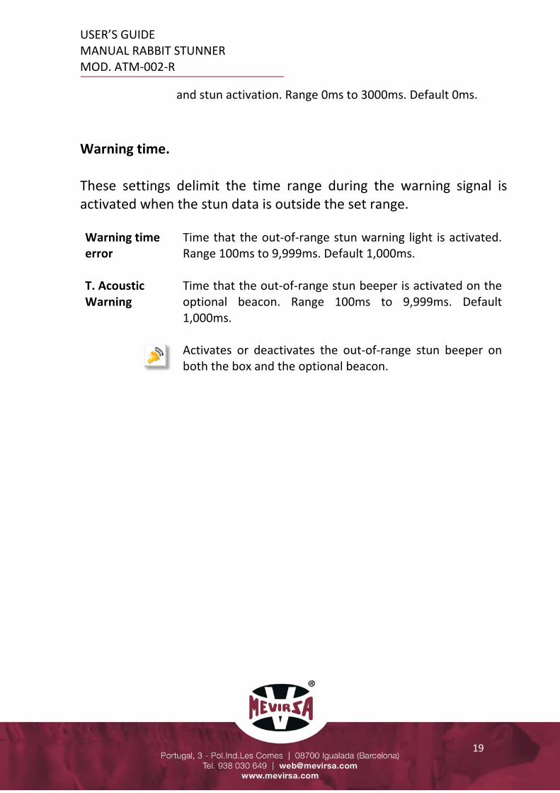
and stun activation. Range 0ms to 3000ms. Default 0ms.
Warning time. These settings delimit the time range during the warning signal is activated when the stun data is outside the set range. Warning time error
Time that the out‐of‐range stun warning light is activated. Range 100ms to 9,999ms. Default 1,000ms.
T. Acoustic Warning
Time that the out‐of‐range stun beeper is activated on the optional beacon. Range 100ms to 9,999ms. Default 1,000ms. Activates or deactivates the out‐of‐range stun beeper on both the box and the optional beacon.

USER’S GUIDE MANUAL RABBIT STUNNER MOD. ATM‐002‐R
20
Concept overview: Correct stunning
Condition: 1. The stunning time must be greater than Minimum time. 2. And the current (intensity) must be higher than the I. Minimum
Indication: 1. The counter of correct stuns is incremented.
Wrong stunning
Condition: 1. The stunning time is less than the Minimum time. 2. Or current is less than I. Minimum. Indication:
1. Incorrect stun counter is increased. Stun indication in recommended range
Condition: 1. The stunning time must be between Min. T. and Max. T. 2. And the current (intensity) must be between I. Minimum and I. Maximum. Indication: 1. The green indicator pilot in the panel lights up. 2. The monitor displays a green band in the measurement area.
Indication of stun out of recommended range
Condition: 1. The stunning time is less than Min. T. or greater than Max. T. 2. Either the current is less than the I. Minimum or greater than the I.
Maximum. Indication: 1. The red pilot comes on in the panel. 2. The monitor shows a red stripe in the measurement area. 3. The acoustic signal will sound if activated.

USER’S GUIDE MANUAL RABBIT STUNNER MOD. ATM‐002‐R
21
2.4.4 USB FILES CONFIGURATION
Enables the generation of stun log files in CSV format on the USB memory stick.
The measurements corresponding to each stun are stored in records internally in the controller for later consultation on screen, with a capacity of 500 records. In order not to lose records when this limit is exceeded, they are saved in CSV files on the USB memory stick. See the chapter Records and File Recording and the chapter Files. Deactivated They do not save records to USB. The last 500 records are
displayed on the display.
Activated Records are saved in CSV files on the USB stick. By default activated.
The activation of the generation of files in CSV format on the USB memory stick is independent of the configuration for sending data to the server. Activating this option implies periodically picking up the USB memory stick to extract the files for consultation and backup, as well as deleting them to free up space on the USB memory stick.

USER’S GUIDE MANUAL RABBIT STUNNER MOD. ATM‐002‐R
22
2.4.5 SERVER CONFIGURATION
Allows configuring the sending of stun logs to a server on the local network via an ethernet connection.
This functionality allows the stun records to be automatically retrieved from a server without having to travel to the machine to retrieve the USB stick with the data. The measurements for each stun are temporarily stored in logs internally in the controller. Periodically, as configured, the logs are sent to the server and deleted from the controller. Deactivated No logs are sent or saved. It is mandatory to select this option
when the machine is not connected to a server. By default deactivated. If before selecting this option there are records pending to be sent, confirmation will be requested, because when sending to the server is deactivated they will be deleted.
Activated Logs are saved and sent to the server at the configured rate.
On pause They are saved, but no logs are sent to the server. Use when the server is temporarily unavailable and you do not want to constantly retry your connection. Switching from Paused to Enabled will allow all retained logs to be sent.

USER’S GUIDE MANUAL RABBIT STUNNER MOD. ATM‐002‐R
23
Minimum records to be sent. When the number of pending records to be sent reaches this value, the records will be sent to the server. If you want to receive records to the server quickly as they are generated, set a low value. Range 1 to 3000. Default 100. Minutes without new records to send. When these minutes pass without any stun, i.e. without generating a new record, the pending records will be sent to the server. This allows to finish sending the last block of records that does not reach the minimum number to send, when a lack of activity in the machine is detected. Range 1 to 1440. Default 5. If error, repeat sending every (minutes). If, when trying to send a block of records, an error occurs with the server that prevents it, the sending will be reattempted at the indicated rate. Range from 0 to 1440. Default 10. If 0, no resend attempt is made. Important. If the logs cannot be sent to the server because there is a connection error or because Pause is selected, the controller will store up to 3,000 logs, at which point the logs will be dumped to a file on the USB memory stick and deleted from the controller. If the USB memory is not available, the most recent 3,000 records will be stored in the controller and the oldest records will be lost. When the connection to the server is restored, the entire list of pending records will be sent, not the ones on the USB stick or the lost ones. To use this functionality, special software must be installed on the server provided by MEVIRSA. This software receives the records and saves them in CSV files on the server's hard disk. See chapter Files and Server.

USER’S GUIDE MANUAL RABBIT STUNNER MOD. ATM‐002‐R
24
2.4.6 LANGUAGE CONFIGURATION
Allows you to select the language of the texts on the screens. The options are as shown in the image.
2.4.7 RECORDS AND SAVING OF FILES
Allows the consultation of the stunning records and control of the saving of the files.
The list shows the last 500 stun records made, the columns that are not visible are on the right side of the screen. They are ordered from most recent to oldest, from top to bottom respectively. The columns indicate date and time of recording, record number, time, intensity, voltage and frequency.
USER’S GUIDE MANUAL RABBIT STUNNER MOD. ATM‐002‐R
25
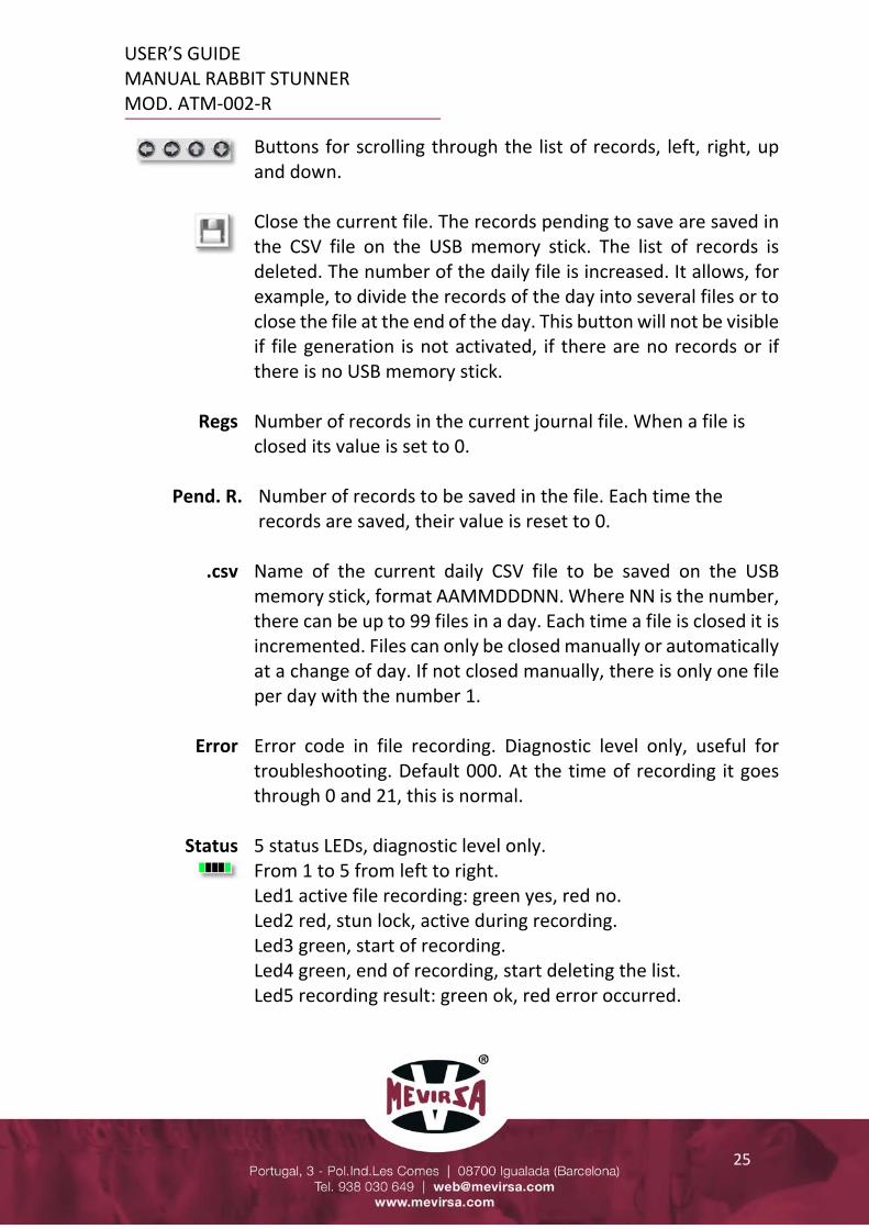
Buttons for scrolling through the list of records, left, right, up and down.
Close the current file. The records pending to save are saved in the CSV file on the USB memory stick. The list of records is deleted. The number of the daily file is increased. It allows, for example, to divide the records of the day into several files or to close the file at the end of the day. This button will not be visible if file generation is not activated, if there are no records or if there is no USB memory stick.
Regs Number of records in the current journal file. When a file is closed its value is set to 0.
Pend. R. Number of records to be saved in the file. Each time the records are saved, their value is reset to 0.
.csv Name of the current daily CSV file to be saved on the USB memory stick, format AAMMDDDNN. Where NN is the number, there can be up to 99 files in a day. Each time a file is closed it is incremented. Files can only be closed manually or automatically at a change of day. If not closed manually, there is only one file per day with the number 1.
Error Error code in file recording. Diagnostic level only, useful for troubleshooting. Default 000. At the time of recording it goes through 0 and 21, this is normal.
Status
5 status LEDs, diagnostic level only. From 1 to 5 from left to right. Led1 active file recording: green yes, red no. Led2 red, stun lock, active during recording. Led3 green, start of recording. Led4 green, end of recording, start deleting the list. Led5 recording result: green ok, red error occurred.

USER’S GUIDE MANUAL RABBIT STUNNER MOD. ATM‐002‐R
26
Starting from the beginning, the records are stored only in the controller, when they reach 500 they are saved in a file on the USB memory stick with a temporary name SA00001.CSV, every 500 new records are dumped in the file, although the screen always shows the last 500 at any given moment. When the file is closed, the unsaved pending records are saved and the file is renamed to AAMMDDNN.CSV where AA is the year, MM month, DD day and NN file number, the date indicates the day to which the records belong. These files are located in the folder F:\SAMP01 on the USB memory stick. The file is closed manually by pressing the button on the display or automatically when a change of day is detected. The change of day is detected when the machine is switched on at midnight or when the machine is switched on the next day. If when trying to save the records in the file, there is a problem with the USB memory, the records are not deleted from the list, but if new records over 500 are entered, records will be lost. It is mandatory to always have a memory stick connected to the USB port, while it is running. See the chapter Files.

USER’S GUIDE MANUAL RABBIT STUNNER MOD. ATM‐002‐R
27
2.4.8 RECORDS AND SENDING TO SERVER
Allows the consultation of the records pending to be sent to the server and to control the sending.
This screen is similar to the one explained in the previous section. In this case, only the records pending to be sent to the server are shown. They are different lists that work independently with independent record numbers. This list of records is filled until the number of records required to be sent to the server is reached, at that point they are sent and deleted from the screen. New records will fill the screen again, and so on. When enough time has elapsed without a stun, i.e. without a new record, the pending records will be sent to the server.
Buttons for scrolling through the list of records, left, right, up and down.
Send to server manually. The current list of records is sent to the server and deleted from the screen. This button will not be visible if there are no pending records.
Regs Number of records made during the day. When the day is changed, the counter is reset.
Pend R. Number of records pending to be sent to the server. Each time records are sent, its value is set to 0.

USER’S GUIDE MANUAL RABBIT STUNNER MOD. ATM‐002‐R
28
Sent R. Number of records sent to the server on the day. Its value is reset at day change. The sum of Pend R. plus Sent R will normally be Regs, although at day change they are all reset except Pend. R.
Bkp Nbr. Number of backup files. If the maximum of 3,000 records to be sent is reached, before they are lost, they are saved in a file on the USB memory stick and deleted from the screen and Pend R. = 0. Indicates the number of files saved, its value should always be 0.
Error Error code in sending logs. Diagnostic level only, useful for troubleshooting. Default 0.
Status
5 status LEDs, diagnostic level only. From 1 to 5 from left to right. Led1 active file recording: green yes, red no. Led2 red, stun lock, active during recording. Led3 green, start of recording. Led4 green, end of recording, start deleting the list. Led5 recording result: green ok, red error occurred.
Although each new record can be configured to be sent to the server, it is usual to optimise the sending in blocks of records that will be sent as they are created, and after a period of time without generating records, the rest of the pending records will be sent. In the event that the records cannot be sent to the server due to a connection problem or because the Pause option is selected, up to 3,000 records will be saved on the screen, at which point they will be saved in a backup file on the USB memory stick and deleted from the controller. If the USB memory stick fails, they will not be deleted from the display, but if new records come in, old records will be lost. See chapter Files and chapter Server.

USER’S GUIDE MANUAL RABBIT STUNNER MOD. ATM‐002‐R
29
2.4.9 PRODUCTION STATISTICS
This screen shows very useful production information.
During the operation of the machine, correct and wrong stuns are counted and their percentage of the total number of stuns is calculated. There are two groups of counters named Partial counter and Total counter, but they do the same thing independently, they have their own reset button, with the intention to use them at convenience, e.g. one for a daily reset and one for a monthly reset. Remember that only those records that do not exceed the Min. intensity or Min. time are counted as erroneous records, those that exceed the Max. time or Max. intensity are counted as correct but are signalled, just like the erroneous ones, visually and acoustically to indicate stun out of the desired range.
Press and hold for more than 2 seconds to reset the counters.

USER’S GUIDE MANUAL RABBIT STUNNER MOD. ATM‐002‐R
30
2.5 FILES CSV files on USB memory These files are generated daily or manually and contain the stunning records. They are located in the folder F:\SAMP0101. They are delimited separated text files. The name of the files is YYMMDDNN.CSV where YY is the year, MM month, DD day of the date to which the records belong and the NN the file number within the same day, range 1 to 99. They contain the header "Date", "Time", "N", "ms", "mA", "V", "Hz" and a row for each record, which are values enclosed in inverted commas and separated by a comma. The "N" column is the record number within the file. File example 20111901.CSV "Date","Time","N","ms","mA","V","Hz" "2020/11/19","16:05:43"," 1","1510","1000","240","50" "2020/11/19","16:06:45"," 2","1530","1050","240","50" "2020/11/19","16:07:46"," 3","1520","1080","240","50" Backup files CSV in USB memory from Server sending These files are only generated when the records cannot be sent to the server and the number of pending records exceeds 3,000. To avoid losing the records, these files are generated for security reasons as a backup, but this is not the normal way of working. These files are located in the folder F:SAMP02\. They are delimited separated text files. The name of the files is SANNNNN_YYYYYMMDD.CSV where YYYY is the year, MM month, DD day of the date the file was generated and NNNNN the backup file number, from 0 to 99999. This number is perpetual and is reset to 0 when the limit is reached. They contain the header "Date", "Time", "N", "ms", "mA", "V", "Hz" and a row for each record, they are values in quotation marks and separated by commas. The column "N" is the record number within the day.

USER’S GUIDE MANUAL RABBIT STUNNER MOD. ATM‐002‐R
31
File example SA00000_20201119.CSV "Date","Time","N","ms","mA","V","Hz" "2020/11/19","16:05:43"," 1","1510","1000","240","50" "2020/11/19","16:06:45"," 2","1530","1050","240","50" "2020/11/19","16:07:46"," 3","1520","1080","240","50" CSV files generated on the server These files are generated on the server upon receipt of the records sent by the controller and contain the stun records. When the first block of records is received, the daily file is generated, and each new block of records is added to the same file. When the server changes day and new records are received, a new file is generated with the new date. If during the current day not all the records of the day are sent, the pending records will be sent the next day and placed in the next day's file. To avoid this, it is necessary to ensure that all pending records of the day are sent before stopping the stunner or stopping the server. A correct setting of the "minutes without new log to send" parameter of the stunner ensures that this does not happen. It doesn't matter too much if the logs are in one file or another as the important thing is the time stamp that each log has. They are found by default in the folder C:\MEVIRSA\STUNNER. They are delimited‐separated text files. The name of the files is STUNNER1_YYYY_MM_DD.CSV where YYYY is the year, MM month, DD day of the date the file is created. If there is more than one stunner, STUNNER2 and successive stunners shall be used. They contain the header "Date", "Time", "N", "ms", "mA", "V", "Hz" and a row for each record, which are values enclosed in inverted commas and separated by a comma. The "N" column is the record number within the file. See chapter Server and chapter Records and sending to server.
USER’S GUIDE MANUAL RABBIT STUNNER MOD. ATM‐002‐R
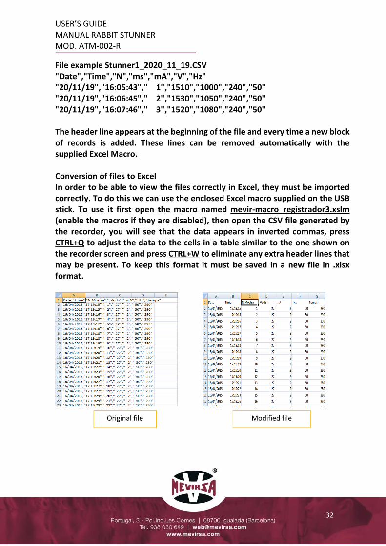
32
File example Stunner1_2020_11_19.CSV "Date","Time","N","ms","mA","V","Hz" "20/11/19","16:05:43"," 1","1510","1000","240","50" "20/11/19","16:06:45"," 2","1530","1050","240","50" "20/11/19","16:07:46"," 3","1520","1080","240","50" The header line appears at the beginning of the file and every time a new block of records is added. These lines can be removed automatically with the supplied Excel Macro. Conversion of files to Excel In order to be able to view the files correctly in Excel, they must be imported correctly. To do this we can use the enclosed Excel macro supplied on the USB stick. To use it first open the macro named mevir‐macro_registrador3.xslm (enable the macros if they are disabled), then open the CSV file generated by the recorder, you will see that the data appears in inverted commas, press CTRL+Q to adjust the data to the cells in a table similar to the one shown on the recorder screen and press CTRL+W to eliminate any extra header lines that may be present. To keep this format it must be saved in a new file in .xlsx format.
Original file Modified file

USER’S GUIDE MANUAL RABBIT STUNNER MOD. ATM‐002‐R
33
2.6 SERVER In order to use the functionality of sending logs to the server, it is necessary to purchase, install and configure the Pro‐Server software supplied by MEVIRSA. This installation process can be done remotely without having to travel to the client's home. Each stunner sends the records, at the rate configured in the stunner, to this software, which saves them in an independent daily file per stunner and day in the server folder that is configured. Regardless of the rate at which the records arrive, they will be added to the daily file. Once the files are on the server, they can be used in the same way as those generated on the USB memory stick. Multiple stunners can be connected to the same software. This software must always be running as it communicates with the stunners to receive the logs and save them to files. It is unattended and has no user interface and can be run as a Windows service. Important to consult chapter Servidor configuration, chapter Records and Sending to server and chapter Files, where all the necessary information is detailed.
SERVER
LOCAL NETWORK
STUNNERS

USER’S GUIDE MANUAL RABBIT STUNNER MOD. ATM‐002‐R
34
2.7 REMOTE CONTROL In order to use the remote control functionality of the stunner it is necessary to purchase, install and configure the Remote HMI software supplied by MEVIRSA. This installation process can be done remotely without having to travel to the customer's home. Remote control consists of being able to access the stunner screen remotely from a PC connected to the same local network. On the PC monitor we will see the screen as if we were in front of the stunner and we will be able to interact with it.
The image shows an example with 4 stunners configured, to access any of them simply click on it.

USER’S GUIDE MANUAL RABBIT STUNNER MOD. ATM‐002‐R
35
When you click on one of the accesses, a connection is made through the local network with the stunner and a window appears as shown in the following image.
It is possible to have multiple windows open simultaneously, i.e. you can see as many stunners as you want in real time. By clicking on the screen with the mouse as if it were your finger, you can navigate through the stunner screen.
Close the window and connect to the stunner.
Allows you to enable/disable screen touches to be operational. It is used to avoid pressing by mistake.
Save an image file with the content of the screen.
Synchronous mode: interactions with the screen are mirrored on the stunner screen. Asynchronous mode: interactions are not reflected on the stunner screen, the original screen is maintained. Change with the menu Operations ‐Synchronous / Asynchronous.

USER’S GUIDE MANUAL RABBIT STUNNER MOD. ATM‐002‐R
36
2.8 USB CONNEXION NOTE: For safety reasons, it is recommended that the control panel is switched off when connecting or disconnecting the USB memory stick. In standard boxes (without double transparent doors) the USB port for connecting and disconnecting the memory stick is located inside the box to keep it away from humidity.
USB connexion

USER’S GUIDE MANUAL RABBIT STUNNER MOD. ATM‐002‐R
37
2.9 MANDATORY SAFETY GLOVES CHARACTERISTICS
Description of the characteristics of the electrical protection gloves which are of mandatory use with the AT‐004 stunner:
MODELO DE REFERENCIA

USER’S GUIDE MANUAL RABBIT STUNNER MOD. ATM‐002‐R
38
2.10 CLEANING AND MAINTENANCE DAILY: At the end of a workday, carefully clean the machine of all residues. For that purpose you should do: 1º Unplug the machine. Clean the tray (the work area that gets dirty) on the stunner with water, making sure NOT to get water directly on the electrical interconnection box on the bottom of the tray. 2º Do not get the sensors directly wet (7) (inductive sensors). Covering the electrical interconnection box is mandatory (as shown below) for the daily cleaning; otherwise, the machine may begin operating poorly.
VERY IMPORTANT NOVA MEVIR S.L. IS NOT LIABLE FOR ANY DAMAGES CAUSED DUE TO NEGLIGENCE OR IMPROPER USE OF THE MACHINE.
Example protection of electrical elements for daily cleaning.
USER’S GUIDE MANUAL RABBIT STUNNER MOD. ATM‐002‐R
39
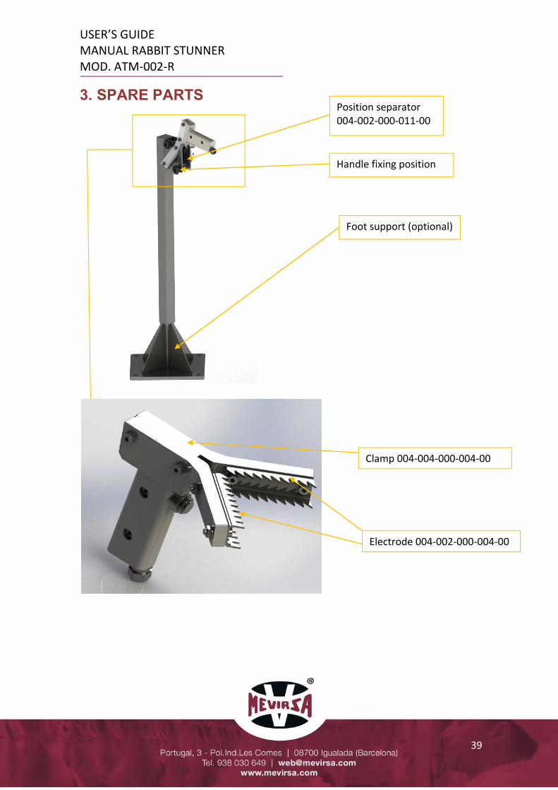
3. SPARE PARTS
Electrode 004‐002‐000‐004‐00
Clamp 004‐004‐000‐004‐00
Position separator 004‐002‐000‐011‐00
Handle fixing position
Foot support (optional)

USER’S GUIDE MANUAL RABBIT STUNNER MOD. ATM‐002‐R
40
4. SAFETY, WARNINGS AND CALIBRATION This section emphasizes the importance of closely following the safety notes found throughout the guide and provides a short explanatory list of the safety pictograms on the machine:
Meaning: “Electrical danger”. Found in the main electrical cabinet is the recorder (optional) and connection box (on the bottom of the tray), which is where the electricity moves from the power supply to the stunner. Do not clean with water and protect when cleaning is being done nearby.
400V single‐phase AC is a hazardous voltage for people. BE CAREFUL WHEN HANDLING THESE ELEMENTS IF THEY ARE NOT DISCONNECTED FROM THE POWER SUPPLY. USING INSULATED SAFETY GLOVES IS MANDATORY WHEN USING THE AT‐004 STUNNER. VERY IMPORTANT NOVA MEVIR, S.L. IS NOT LIABLE FOR ANY DAMAGES CAUSED DUE TO NEGLIGENCE OR IMPROPER USE OF THE MACHINE. It’s recommended, every three months, make a comparison between the voltage and current data on the display and the practical data taken directly at the electrodes. A calibration of the equipment by MEVIRSA would be required ONCE A YEAR.