manual retu
DESCRIPTION
retuTRANSCRIPT

RETU Installation Instruction
Installation Instructions
1/1531-CNH 160 267/1 Uae U

Copyright
© Copyright Ericsson AB 2006–2009. All rights reserved.
Disclaimer
No part of this document may be reproduced in any form without the writtenpermission of the copyright owner. The contents of this document are subjectto revision without notice due to continued progress in methodology, designand manufacturing.
Ericsson shall have no liability for any error or damage of any kind resultingfrom the use of this document.
1/1531-CNH 160 267/1 Uae U | 2009-09-17

Contents
Contents
1 Introduction 1
1.1 Target Group 1
2 Prerequisites 1
2.1 Documentation 1
2.2 Tools and Equipment 1
3 RETU Installation Procedure 4
3.1 Checking Deliveries and Unpacking RETUs 4
3.2 Shutting Down Power 5
3.3 Connecting RETUs to Antennas 5
3.4 Connecting RETUs to ASC KRY 112 42/4 or ASC KRY112 134/1 6
3.5 Connecting RETUs to RRUs 8
3.6 Connecting RETUs to RIUs 11
3.7 Connecting RETUs to TMAs 11
3.8 Connecting RETUs to other RETUs (Cascading) 12
3.9 Connecting RETUs to ASC KRY 112 42/2 and ASC KRY112 42/3 12
3.10 Testing the Antenna System 14
3.11 Sealing the Connector 14
3.12 Powering Up the Antenna System 16
3.13 Calibrating the RETU 16
4 Concluding Routines 17
Reference List 19
1/1531-CNH 160 267/1 Uae U | 2009-09-17

RETU Installation Instruction
1/1531-CNH 160 267/1 Uae U | 2009-09-17

Prerequisites
1 Introduction
This document describes the installation of a Remote Electrical Tilt Unit (RETU)on an antenna with adjustable electrical tilt.
The RETU is available with two different communication interfaces; Ericssonproprietary and 3GPP/AISG 2.0. If nothing else is mentioned the instructionsapplies for all versions.
1.1 Target Group
The target groups for these instructions are on-site service and installationpersonnel.
Technicians working on Ericsson products or systems must have the necessarytraining and competence in order to perform their work correctly.
2 Prerequisites
The following general conditions must apply before performing this installation:
2.1 Documentation
Ensure that the following documents have been read and understood:
• Personal Health and Safety Information
• System Safety Information
See document Reference List on page 19 for other documents.
2.2 Tools and Equipment
The following tools and equipment are required:
11/1531-CNH 160 267/1 Uae U | 2009-09-17

RETU Installation Instruction
2.2.1 Tools
The following tools are required for the installation:
• Side cutters or knife
• 13 mm combination wrench
• Cable clamps
• Flat-bladed screwdriver
2.2.2 Equipment
This section describes the equipment required for the installation. Theequipment depends on the type of hardware.
• Sealing set, NTM 201 2426
• Cable or cable kit, according to tables below.
Table 1 shows the cables available when connecting an RETU to thefollowing:– Radio Remote Unit W (RRUW)– RET Interface Unit (RIU), KRC 115 032/2– Tower-Mounted Amplifier (TMA) with 3GPP/AISG 2.0 interface– Another RETU in a cascading chain
Table 1 RETU Cables and Cable Kits
Cable Cable Color Cable Length
1/TSR 484 21/1000(1) Black 1 meters
1/TSR 484 21/2000 (1) Black 2 meters
1/TSR 484 21/3000 (1) Black 3 meters
1/TSR 484 21/15M Black 15 meters
1/TSR 484 21/1000 Gray 1 meters
1/TSR 484 21/2000 Gray 2 meters
1/TSR 484 21/3000 Gray 3 meters
1/TSR 484 21/15M Gray 15 meters
(1) AISG Standard Cable
• Table 2 shows the cables available when connecting an RETU to thefollowing:– Antenna System Controller (ASC) KRY 112 42/4– Antenna System Controller (ASC) KRY 112 134/1– Radio Remote Unit 11 (RRU11)– Radio Remote Unit 22 (RRU22)
2 1/1531-CNH 160 267/1 Uae U | 2009-09-17

Prerequisites
– RIU, KRC 115 032/1
Table 2 RETU Cables
Cable Cable Color Cable Length
TSR 484 31/1500 Black 1 meters
TSR 484 31/2500 Black 2 meters
TSR 484 31/3500 Black 3 meters
TSR 484 31/15M Black 15 meters
TSR 484 32/1500 Gray 1 meters
TSR 484 32/2500 Gray 2 meters
TSR 484 32/13500 Gray 3 meters
TSR 484 32/15M Gray 15 meters
• Table 3 shows the cables available when connecting an RETU to thefollowing:- ASC, KRY 112 42/2- ASC, KRY 112 42/3
Table 3 RETU Cables and Cable Kits
Cable Kit(1) Cable in Cable Kit CableColor
Cable Length(m)
NTM 503 94/1000 1/TSR 484 21/1000(2) Black 1
NTM 503 94/2000 1/TSR 484 21/2000 (1) Black 2
NTM 503 94/3000 1/TSR 484 21/3000 (1) Black 3
NTM 503 94/15M 1/TSR 484 21/15M Black 15
NTM 503 95/1000 1/TSR 484 21/1000 Gray 1
NTM 503 95/2000 1/TSR 484 21/2000 Gray 2
NTM 503 95/3000 1/TSR 484 21/3000 Gray 3
NTM 503 95/15M 1/TSR 484 21/15M Gray 15
(1) Contains cold shrink tube MPB 111 13/1 and metal cable gland SXK 120 2260/1.(2) Antenna Interface Standards Group (AISG) cable.
31/1531-CNH 160 267/1 Uae U | 2009-09-17

RETU Installation Instruction
3 RETU Installation Procedure
This section describes the procedures when installing the RETU.
P0208
Reading Instructions
Checking Deliveries
Shutting DownPower
Testing AntennaSystem
Powering UpAntenna System
Concluding Routines
Sealing Connectors
Calibrating RETUs
Connecting RETUsto Antennas
ConnectingRETUs to RRUs
ConnectingRETUs to ASCs
ConnectingRETUs to RIUs
ConnectingRETUs to TMAs
ConnectingRETUs to other
RETUs(Cascading)
Figure 1 RETU Installation Flowchart
3.1 Checking Deliveries and Unpacking RETUs
To check the delivery, do the following:
4 1/1531-CNH 160 267/1 Uae U | 2009-09-17
RETU Installation Procedure
1. Inspect the delivery box for any damage. If the box is damaged, reportaccording to local procedures.
2. Unpack the RETU and check that the delivery is correct according to theSite Installation Documentation, Reference [3].
3.2 Shutting Down Power
The site must be taken out of traffic in a controlled way and the RadioFrequency (RF) and DC power to the feeder system must be shut down beforedisconnecting cables.
To shut down power, see relevant sections in document Replacing RadioUnits, Reference [4].
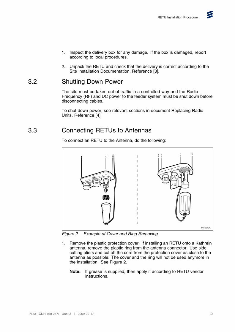
3.3 Connecting RETUs to Antennas
To connect an RETU to the Antenna, do the following:
P019072A
Figure 2 Example of Cover and Ring Removing
1. Remove the plastic protection cover. If installing an RETU onto a Kathreinantenna, remove the plastic ring from the antenna connector. Use sidecutting pliers and cut off the cord from the protection cover as close to theantenna as possible. The cover and the ring will not be used anymore inthe installation. See Figure 2.
Note: If grease is supplied, then apply it according to RETU vendorinstructions.
51/1531-CNH 160 267/1 Uae U | 2009-09-17

RETU Installation Instruction
P019073A
Figure 3 Example of RETU to Antenna fastening
2. Insert the RETU in the steering slots, and tighten the screw connector firmlyby hand or according to RETU vendor instructions.
3.4 Connecting RETUs to ASC KRY 112 42/4 or ASCKRY 112 134/1
This section describes how to connect the RETU to an ASC, KRY 112 42/4 orASC, KRY 112 134/1.
6 1/1531-CNH 160 267/1 Uae U | 2009-09-17

RETU Installation Procedure
P016755A
RETU
Antenna
ASC
Figure 4 Cable between RETU and ASC
To connect an RET cable an ASC, do the following:
1. Connect the applicable cable to the RETU and tighten it firmly by hand.
2. Remove the protective cap from the ASC RETU connector using ascrewdriver.
3. Connect the cable to the ASC and tighten it to a torque of 0.4–0.6 Nm.
Note: This connector should not be sealed.
71/1531-CNH 160 267/1 Uae U | 2009-09-17

RETU Installation Instruction
3.5 Connecting RETUs to RRUs
This section describes how to connect an RETU to a RRU11, RRU22 or RRUW.
To connect an RET cable to the RRU, do the following:
Note: The type of RRU determines cable types used (see Table 1 and Table2).
8 1/1531-CNH 160 267/1 Uae U | 2009-09-17

RETU Installation Procedure
1. Remove the protective cap fromthe RET connector by turning itcounterclockwise, using a 5.5 mmflat-bladed screw driver.
P015612B
RET
RRU11
_out
PT_IinOPT
B000026A
RRU22
P020483A
RRUW91/1531-CNH 160 267/1 Uae U | 2009-09-17

RETU Installation Instruction
2. Connect the RET cable to the RETconnector and tighten the connectorcollar clockwise by hand.Seal the RET connector. SeeSection 3.11 Sealing the Connectoron page 14
RET
A015613A
RRU11
OPT_IN
RET
OPT.OUTPWR
B000028A
RRU22
P020484A
RRUW
10 1/1531-CNH 160 267/1 Uae U | 2009-09-17

RETU Installation Procedure
3.6 Connecting RETUs to RIUs
To connect an RETU to an RIU, do the following:
Note: The type of RIU determines cable types used (see Table 1 and Table 2).
P017194A
Antenna
RIU
RETU
Figure 5 Example of RETU to RIU Connection
1. Connect the applicable cable to the RETU and tighten it firmly by hand.
2. Remove the protective cap from the RIU RETU connector.
3. Connect the cable to the RIU and tighten it firmly by hand.
3.7 Connecting RETUs to TMAs
To connect an RETU with 3GPP/AISG 2.0 interface to a TMA with 3GPP/AISG2.0 interface, do the following:
1. Connect the relevant cable to the RETU and tighten it firmly by hand.
2. Remove the protective cap from the TMA RETU connector.
3. Connect the cable to the TMA and tighten it firmly by hand.
111/1531-CNH 160 267/1 Uae U | 2009-09-17

RETU Installation Instruction
3.8 Connecting RETUs to other RETUs (Cascading)
To connect an RETU with 3GPP/AISG 2.0 interface to another RETU with3GPP/AISG 2.0 interface in a cascading chain, do the following:
P020964A
Figure 6 RETU Cascading Connection
1. Connect the relevant cable on the first RETU and tighten it firmly by hand.
2. Remove the protective cap from the second RETU connector.
3. Connect the cable to the second RETU and tighten it firmly by hand.
4. If required, repeat steps 1 to 3 to install more RETUs in the cascading chain.
3.9 Connecting RETUs to ASC KRY 112 42/2 and ASCKRY 112 42/3
This section describes how to connect the RETU to an ASC, KRY 112 42/2or an ASC, KRY 112 42/3 connector.
12 1/1531-CNH 160 267/1 Uae U | 2009-09-17

RETU Installation Procedure
Figure 7 Cable between RETU and ASC
To connect the RETU to the ASC, do the following:
1. Connect the applicable cable to the RETU and tighten it firmly by hand.
2. Remove the protective cap from the ASC RETU connector using a13 mm combination wrench.
3. Unpack the cold shrink tube and the threaded metal cable gland. SeeFigure 8 for details.
4. Holding the shrink tube, release a sufficient length of the plastic spiralband to enable it to pass through the tube and leave enough to grasp atthe other end.
5. Pass the shrink tube over the cable with the end of the plastic band facingaway from the connector.
6. Pass the metal cable gland over the cable. See Figure 8.
131/1531-CNH 160 267/1 Uae U | 2009-09-17

RETU Installation Instruction
Figure 8 Cold Shrink Kit on Cable
7. Connect the cable to the ASC and tighten it firmly by hand, see Figure 9.
Figure 9 RETU Cable Connection to ASC with Top-Mounted Connector
3.10 Testing the Antenna System
Test the antenna system tests before the connectors on the units are sealed.For instructions on how to test the antenna system, see WCDMA AntennaSystem Test Instruction, Reference [5].
3.11 Sealing the Connector
This section provides the following instructions:
14 1/1531-CNH 160 267/1 Uae U | 2009-09-17

RETU Installation Procedure
• Sealing with self-fusing (self-amalgamating) tape and insulation tape onan RETU cable connector
• Applying a water drop loop on an RETU cable, when relevant.
Note: Before sealing the connector, make sure it is properly tightened andfree from moisture.
3.11.1 Sealing the RETU cable Connector
To seal a connector on the RETU cable using the sealing set, do the following:
1. Make sure that the connector is clean and dry to avoid dirt and moisturebeing trapped under the tape.
2. On the connector, start applying the self-fusing tape 50 mm below the edgeof the connector of the cable. Varying the stretching of the tape, wrap alongthe cable onto the connector, overlapping each turn by 50%. Continuewrapping onto the connector chassis.
Note: Avoid leaving gaps in the tape.
Figure 10 Applying Tape on the RETU Cable Connector
3. Apply two half-overlapped layers of insulation tape (electrotape) over theself-fusing tape. Start each layer 30 mm below the end of the self-fusingtape and continue wrapping onto the connector chassis.
4. Make sure that there are no gaps in the insulation tape, and that the sealingcompletely covers the connector.
151/1531-CNH 160 267/1 Uae U | 2009-09-17

RETU Installation Instruction
3.11.2 Applying a Water Drip Loop on the RETU Cable
To ensure that as much water as possible is led away from an RETU connectoron a ASC, KRY 112 42/3, or ASC, KRY 112 42/3, a drip loop must be appliedon the RETU cable.
To apply a drip loop, perform the following steps:
1. Bend the cable close to the RETU connector on the ASC. The bendingradius of the cable must not be less than 20 mm.
2. Use a cable strap to fasten the cable to the antenna jumper. Ensure thatthe cable leaves the shrink tube in a straight line, with no gap between thecable and the shrink tube.
The cable is now forming a drip loop, see Figure 11.
P012940D
50
Unit of measurement: mm
Figure 11 RETU Cable with Drip Loop
3.12 Powering Up the Antenna System
To power up the antenna system, follow the instructions in relevant sections ofdocument Replacing Radio Units, Reference [4].
3.13 Calibrating the RETU
To calibrate an RETU, follow the instructions in document ModifyingConfigurations, Reference [6].
16 1/1531-CNH 160 267/1 Uae U | 2009-09-17

Concluding Routines
4 Concluding Routines
Before leaving the site, ensure the following:
• The Operating and Maintenance Center (OMC) or Network ManagementCenter (NMC) is informed that the installation procedure is completedinstructions from the OMC or NMC are followed
• All connectors of the unit are correctly connected and, if applicable, sealed
• All tools are collected
• The RBS cabinet door is closed and locked
• The work order is completed
• The site is clean and waste disposed of in accordance with local regulations
• All checklists in the Site Installation Documentation, Reference [3], arecompleted
• The Site Installation Documentation, Reference [3], is updated with the newhardware installed and handed over to the person responsible for the site
• The site is secured and all doors and gates are locked
171/1531-CNH 160 267/1 Uae U | 2009-09-17

RETU Installation Instruction
18 1/1531-CNH 160 267/1 Uae U | 2009-09-17
Reference List
Reference List
[1] Personal Health and Safety Information, 124 46-2885
[2] System Safety Information, 124 46-2886
[3] Site Installation Documentation (specific for the site)
[4] Replacing Radio Units (see relevant cabinet documentation)
[5] WCDMA Antenna System Test Instruction, 3/1532 LZA 701 0003
[6] Modifying Configurations, 126/1543-LZA 701 6003
191/1531-CNH 160 267/1 Uae U | 2009-09-17