manual: rosemount™ 2140 level detector - emerson · 00809-0100-4140, rev aa introduction january...
TRANSCRIPT
Reference Manual00809-0100-4140, Rev AA
January 2017
Rosemount™ 2140 Level DetectorVibrating Fork


Reference Manual 00809-0100-4140, Rev AA
ContentsJanuary 2017
Contents
1Section 1: Introduction1.1 Models covered . . . . . . . . . . . . . . . . . . . . . . . . . . . . . . . . . . . . . . . . . . . . . . . . . . . . . . . 1
1.2 Point level detector overview. . . . . . . . . . . . . . . . . . . . . . . . . . . . . . . . . . . . . . . . . . . . 1
1.3 Using this manual. . . . . . . . . . . . . . . . . . . . . . . . . . . . . . . . . . . . . . . . . . . . . . . . . . . . . . 2
1.4 Product recycling/ disposal . . . . . . . . . . . . . . . . . . . . . . . . . . . . . . . . . . . . . . . . . . . . . 3
2Section 2: Configuration2.1 Safety messages . . . . . . . . . . . . . . . . . . . . . . . . . . . . . . . . . . . . . . . . . . . . . . . . . . . . . . . 5
2.2 Overview . . . . . . . . . . . . . . . . . . . . . . . . . . . . . . . . . . . . . . . . . . . . . . . . . . . . . . . . . . . . . 5
2.3 Get started with your preferred configuration tool . . . . . . . . . . . . . . . . . . . . . . . . . 6
2.3.1 AMS Device Manager . . . . . . . . . . . . . . . . . . . . . . . . . . . . . . . . . . . . . . . . . . . . 6
2.3.2 Field Communicator . . . . . . . . . . . . . . . . . . . . . . . . . . . . . . . . . . . . . . . . . . . . . 7
2.3.3 Local Operator Interface (LOI) . . . . . . . . . . . . . . . . . . . . . . . . . . . . . . . . . . . . 7
2.4 Switching HART Revision . . . . . . . . . . . . . . . . . . . . . . . . . . . . . . . . . . . . . . . . . . . . . . . 8
2.4.1 Switching HART revision with a generic menu . . . . . . . . . . . . . . . . . . . . . . 8
2.4.2 Switching HART revision with Field Communicator . . . . . . . . . . . . . . . . . . 9
2.4.3 Switching HART Revision with AMS Device Manager . . . . . . . . . . . . . . . . . 9
2.4.4 Switching HART revision with Local Operator Interface. . . . . . . . . . . . . . . 9
2.5 Configuration basics . . . . . . . . . . . . . . . . . . . . . . . . . . . . . . . . . . . . . . . . . . . . . . . . . .10
2.5.1 Setting the security switch . . . . . . . . . . . . . . . . . . . . . . . . . . . . . . . . . . . . . . 10
2.5.2 Setting the loop to manual . . . . . . . . . . . . . . . . . . . . . . . . . . . . . . . . . . . . . . 10
2.6 Configure device using Guided Setup . . . . . . . . . . . . . . . . . . . . . . . . . . . . . . . . . . .10
2.6.1 Guided setup on the AMS Device Manager . . . . . . . . . . . . . . . . . . . . . . . . 10
2.6.2 Guided setup on the Field Communicator . . . . . . . . . . . . . . . . . . . . . . . . . 10
2.6.3 Guided setup on the LOI . . . . . . . . . . . . . . . . . . . . . . . . . . . . . . . . . . . . . . . . 11
2.7 Verify the configuration before installation . . . . . . . . . . . . . . . . . . . . . . . . . . . . . .11
2.7.1 Verifying configuration (Field Communicator or AMS) . . . . . . . . . . . . . . 11
2.7.2 Verifying configuration (LOI) . . . . . . . . . . . . . . . . . . . . . . . . . . . . . . . . . . . . 12
2.7.3 Dynamic variables configuration . . . . . . . . . . . . . . . . . . . . . . . . . . . . . . . . . 13
2.8 Basic setup. . . . . . . . . . . . . . . . . . . . . . . . . . . . . . . . . . . . . . . . . . . . . . . . . . . . . . . . . . .14
2.8.1 Sensor operation mode . . . . . . . . . . . . . . . . . . . . . . . . . . . . . . . . . . . . . . . . . 14
2.8.2 Sensor output delay . . . . . . . . . . . . . . . . . . . . . . . . . . . . . . . . . . . . . . . . . . . . 16
2.8.3 Media density. . . . . . . . . . . . . . . . . . . . . . . . . . . . . . . . . . . . . . . . . . . . . . . . . . 17
2.8.4 Media learn. . . . . . . . . . . . . . . . . . . . . . . . . . . . . . . . . . . . . . . . . . . . . . . . . . . . 19
2.8.5 Allowable change in dry fork frequency . . . . . . . . . . . . . . . . . . . . . . . . . . . 21
IContents
Reference Manual00809-0100-4140, Rev AA
ContentsJanuary 2017
2.8.6 Sensor fault delay . . . . . . . . . . . . . . . . . . . . . . . . . . . . . . . . . . . . . . . . . . . . . . 22
2.8.7 Analog output type and operating modes . . . . . . . . . . . . . . . . . . . . . . . . . 23
2.8.8 Analog output range points . . . . . . . . . . . . . . . . . . . . . . . . . . . . . . . . . . . . . 26
2.8.9 Scaled Variable damping . . . . . . . . . . . . . . . . . . . . . . . . . . . . . . . . . . . . . . . . 28
2.9 Local Operator Interface (LOI) display . . . . . . . . . . . . . . . . . . . . . . . . . . . . . . . . . . .29
2.9.1 Electronics temperature units . . . . . . . . . . . . . . . . . . . . . . . . . . . . . . . . . . . 30
2.10Detailed setup . . . . . . . . . . . . . . . . . . . . . . . . . . . . . . . . . . . . . . . . . . . . . . . . . . . . . . .31
2.10.1 HART (re-mapping dynamic variables) . . . . . . . . . . . . . . . . . . . . . . . . . . . . 31
2.10.2 Configuring alarm and saturation levels . . . . . . . . . . . . . . . . . . . . . . . . . . . 33
2.10.3 Configuring process alerts. . . . . . . . . . . . . . . . . . . . . . . . . . . . . . . . . . . . . . . 35
2.10.4 Configuring Scaled Variable . . . . . . . . . . . . . . . . . . . . . . . . . . . . . . . . . . . . . 36
2.11Configuring burst mode (optional) . . . . . . . . . . . . . . . . . . . . . . . . . . . . . . . . . . . . .38
2.12System readiness . . . . . . . . . . . . . . . . . . . . . . . . . . . . . . . . . . . . . . . . . . . . . . . . . . . . .40
2.12.1 Confirm correct Device Driver (DD). . . . . . . . . . . . . . . . . . . . . . . . . . . . . . . 40
2.13Establishing multi-drop communications (optional) . . . . . . . . . . . . . . . . . . . . . .40
2.13.1 Communicating with a multi-dropped level detector . . . . . . . . . . . . . . . 41
2.13.2 Changing a level detector polling address . . . . . . . . . . . . . . . . . . . . . . . . . 42
2.14Configuring level detector security . . . . . . . . . . . . . . . . . . . . . . . . . . . . . . . . . . . . .42
2.14.1 Setting the security switch . . . . . . . . . . . . . . . . . . . . . . . . . . . . . . . . . . . . . . 43
2.14.2 HART Lock. . . . . . . . . . . . . . . . . . . . . . . . . . . . . . . . . . . . . . . . . . . . . . . . . . . . . 44
2.14.3 Configuration button lock . . . . . . . . . . . . . . . . . . . . . . . . . . . . . . . . . . . . . . . 44
2.14.4 Local Operator Interface (LOI) password . . . . . . . . . . . . . . . . . . . . . . . . . . 45
2.15Setting the alarm switch . . . . . . . . . . . . . . . . . . . . . . . . . . . . . . . . . . . . . . . . . . . . . .46
3Section 3: Hardware Installation3.1 Safety messages . . . . . . . . . . . . . . . . . . . . . . . . . . . . . . . . . . . . . . . . . . . . . . . . . . . . . .47
3.2 Considerations before installation . . . . . . . . . . . . . . . . . . . . . . . . . . . . . . . . . . . . . .48
3.2.1 Safety considerations . . . . . . . . . . . . . . . . . . . . . . . . . . . . . . . . . . . . . . . . . . . 48
3.2.2 Environmental considerations . . . . . . . . . . . . . . . . . . . . . . . . . . . . . . . . . . . 48
3.2.3 Application considerations . . . . . . . . . . . . . . . . . . . . . . . . . . . . . . . . . . . . . . 49
3.2.4 Installation considerations . . . . . . . . . . . . . . . . . . . . . . . . . . . . . . . . . . . . . . 51
3.2.5 Installation examples . . . . . . . . . . . . . . . . . . . . . . . . . . . . . . . . . . . . . . . . . . . 56
3.3 Installation procedures . . . . . . . . . . . . . . . . . . . . . . . . . . . . . . . . . . . . . . . . . . . . . . . .57
3.3.1 Process connection seals . . . . . . . . . . . . . . . . . . . . . . . . . . . . . . . . . . . . . . . . 57
3.3.2 Correct fork alignment. . . . . . . . . . . . . . . . . . . . . . . . . . . . . . . . . . . . . . . . . . 58
3.3.3 Tightening the threaded Rosemount 2140 . . . . . . . . . . . . . . . . . . . . . . . . 60
3.3.4 Insulation . . . . . . . . . . . . . . . . . . . . . . . . . . . . . . . . . . . . . . . . . . . . . . . . . . . . . 60
II Contents

Reference Manual 00809-0100-4140, Rev AA
ContentsJanuary 2017
4Section 4: Electrical Installation4.1 Safety messages . . . . . . . . . . . . . . . . . . . . . . . . . . . . . . . . . . . . . . . . . . . . . . . . . . . . . .61
4.2 Cable selection . . . . . . . . . . . . . . . . . . . . . . . . . . . . . . . . . . . . . . . . . . . . . . . . . . . . . . .62
4.3 Cable gland/conduit . . . . . . . . . . . . . . . . . . . . . . . . . . . . . . . . . . . . . . . . . . . . . . . . . .62
4.4 Power supply. . . . . . . . . . . . . . . . . . . . . . . . . . . . . . . . . . . . . . . . . . . . . . . . . . . . . . . . .62
4.5 Hazardous areas . . . . . . . . . . . . . . . . . . . . . . . . . . . . . . . . . . . . . . . . . . . . . . . . . . . . . .63
4.6 Wiring diagram. . . . . . . . . . . . . . . . . . . . . . . . . . . . . . . . . . . . . . . . . . . . . . . . . . . . . . .63
4.7 Grounding . . . . . . . . . . . . . . . . . . . . . . . . . . . . . . . . . . . . . . . . . . . . . . . . . . . . . . . . . . .63
4.7.1 Level switch grounding . . . . . . . . . . . . . . . . . . . . . . . . . . . . . . . . . . . . . . . . . 64
4.7.2 Signal cable shield grounding . . . . . . . . . . . . . . . . . . . . . . . . . . . . . . . . . . . . 64
4.7.3 Transient protection terminal block grounding . . . . . . . . . . . . . . . . . . . . 65
4.8 Wiring and power-up. . . . . . . . . . . . . . . . . . . . . . . . . . . . . . . . . . . . . . . . . . . . . . . . . .65
5Section 5: Operation and Maintenance5.1 Overview . . . . . . . . . . . . . . . . . . . . . . . . . . . . . . . . . . . . . . . . . . . . . . . . . . . . . . . . . . . .69
5.2 Safety messages . . . . . . . . . . . . . . . . . . . . . . . . . . . . . . . . . . . . . . . . . . . . . . . . . . . . . .69
5.3 Analog output calibration. . . . . . . . . . . . . . . . . . . . . . . . . . . . . . . . . . . . . . . . . . . . . .70
5.3.1 Trimming the analog output. . . . . . . . . . . . . . . . . . . . . . . . . . . . . . . . . . . . . 70
5.3.2 Site calibration of analog output . . . . . . . . . . . . . . . . . . . . . . . . . . . . . . . . . 70
5.3.3 Restoring factory calibration of the analog output. . . . . . . . . . . . . . . . . . 72
5.4 Performing tests and simulations . . . . . . . . . . . . . . . . . . . . . . . . . . . . . . . . . . . . . . .73
5.4.1 Device tests (partial proof test) . . . . . . . . . . . . . . . . . . . . . . . . . . . . . . . . . . 73
5.4.2 Proof tests. . . . . . . . . . . . . . . . . . . . . . . . . . . . . . . . . . . . . . . . . . . . . . . . . . . . . 75
5.4.3 Verifying alarm level (optional) . . . . . . . . . . . . . . . . . . . . . . . . . . . . . . . . . . 75
5.4.4 Analog loop test (optional) . . . . . . . . . . . . . . . . . . . . . . . . . . . . . . . . . . . . . . 76
5.4.5 Simulate device variables. . . . . . . . . . . . . . . . . . . . . . . . . . . . . . . . . . . . . . . . 77
5.5 Diagnostics and service. . . . . . . . . . . . . . . . . . . . . . . . . . . . . . . . . . . . . . . . . . . . . . . .79
5.5.1 Restart device . . . . . . . . . . . . . . . . . . . . . . . . . . . . . . . . . . . . . . . . . . . . . . . . . 79
5.5.2 Load user defaults . . . . . . . . . . . . . . . . . . . . . . . . . . . . . . . . . . . . . . . . . . . . . . 80
5.5.3 Sensor frequency. . . . . . . . . . . . . . . . . . . . . . . . . . . . . . . . . . . . . . . . . . . . . . . 80
5.5.4 Sensor compensation. . . . . . . . . . . . . . . . . . . . . . . . . . . . . . . . . . . . . . . . . . . 81
5.5.5 Sensor state . . . . . . . . . . . . . . . . . . . . . . . . . . . . . . . . . . . . . . . . . . . . . . . . . . . 82
5.5.6 Sensor status . . . . . . . . . . . . . . . . . . . . . . . . . . . . . . . . . . . . . . . . . . . . . . . . . . 83
5.5.7 Dry fork frequency and switching points . . . . . . . . . . . . . . . . . . . . . . . . . . 85
5.5.8 Counters and timers . . . . . . . . . . . . . . . . . . . . . . . . . . . . . . . . . . . . . . . . . . . . 86
5.6 Dry fork calibration . . . . . . . . . . . . . . . . . . . . . . . . . . . . . . . . . . . . . . . . . . . . . . . . . . .87
5.6.1 Site calibration of dry fork sensor. . . . . . . . . . . . . . . . . . . . . . . . . . . . . . . . . 87
5.6.2 Restoring factory calibration of dry fork sensor. . . . . . . . . . . . . . . . . . . . . 88
IIIContents
Reference Manual00809-0100-4140, Rev AA
ContentsJanuary 2017
5.6.3 Sensor calibration status and calibration count. . . . . . . . . . . . . . . . . . . . . 90
5.6.4 Configuring Power Advisory Diagnostic . . . . . . . . . . . . . . . . . . . . . . . . . . . 90
5.7 Frequency profiling functions . . . . . . . . . . . . . . . . . . . . . . . . . . . . . . . . . . . . . . . . . .94
5.8 Upgrading to Extended Features Package (EFP). . . . . . . . . . . . . . . . . . . . . . . . . . .95
6Section 6: Troubleshooting6.1 Overview . . . . . . . . . . . . . . . . . . . . . . . . . . . . . . . . . . . . . . . . . . . . . . . . . . . . . . . . . . . .97
6.2 Safety messages . . . . . . . . . . . . . . . . . . . . . . . . . . . . . . . . . . . . . . . . . . . . . . . . . . . . . .97
6.3 Troubleshooting for 4-20 mA Output . . . . . . . . . . . . . . . . . . . . . . . . . . . . . . . . . . .98
6.4 Diagnostic messages. . . . . . . . . . . . . . . . . . . . . . . . . . . . . . . . . . . . . . . . . . . . . . . . . .98
6.4.1 Diagnostic message: failed - fix now . . . . . . . . . . . . . . . . . . . . . . . . . . . . . . 99
6.4.2 Diagnostic message: maintenance - fix soon. . . . . . . . . . . . . . . . . . . . . . . 99
6.4.3 Diagnostic message: advisory. . . . . . . . . . . . . . . . . . . . . . . . . . . . . . . . . . .100
6.5 Service support. . . . . . . . . . . . . . . . . . . . . . . . . . . . . . . . . . . . . . . . . . . . . . . . . . . . . 101
AAppendix A: Specifications and Reference DataA.1 Specifications . . . . . . . . . . . . . . . . . . . . . . . . . . . . . . . . . . . . . . . . . . . . . . . . . . . . . . 103
A.1.1 General . . . . . . . . . . . . . . . . . . . . . . . . . . . . . . . . . . . . . . . . . . . . . . . . . . . . . .103
A.1.2 Physical specifications . . . . . . . . . . . . . . . . . . . . . . . . . . . . . . . . . . . . . . . . .103
A.1.3 Performance specifications . . . . . . . . . . . . . . . . . . . . . . . . . . . . . . . . . . . . .104
A.1.4 Electrical specifications . . . . . . . . . . . . . . . . . . . . . . . . . . . . . . . . . . . . . . . .104
A.1.5 Environmental specifications . . . . . . . . . . . . . . . . . . . . . . . . . . . . . . . . . . .104
A.2 Dimensional drawings. . . . . . . . . . . . . . . . . . . . . . . . . . . . . . . . . . . . . . . . . . . . . . . 106
A.3 Ordering information . . . . . . . . . . . . . . . . . . . . . . . . . . . . . . . . . . . . . . . . . . . . . . . 115
A.3.1 Rosemount 2140 Spares and Accessories . . . . . . . . . . . . . . . . . . . . . . . .119
BAppendix B: Product CertificationsB.1 Overview . . . . . . . . . . . . . . . . . . . . . . . . . . . . . . . . . . . . . . . . . . . . . . . . . . . . . . . . . . 121
B.2 European directive information. . . . . . . . . . . . . . . . . . . . . . . . . . . . . . . . . . . . . . . 121
B.3 Ordinary locations certifications . . . . . . . . . . . . . . . . . . . . . . . . . . . . . . . . . . . . . . 121
B.4 Hazardous locations certifications . . . . . . . . . . . . . . . . . . . . . . . . . . . . . . . . . . . . 121
B.4.1 North America and Canada . . . . . . . . . . . . . . . . . . . . . . . . . . . . . . . . . . . . .121
B.4.2 Europe . . . . . . . . . . . . . . . . . . . . . . . . . . . . . . . . . . . . . . . . . . . . . . . . . . . . . . .122
B.4.3 International. . . . . . . . . . . . . . . . . . . . . . . . . . . . . . . . . . . . . . . . . . . . . . . . . .123
CAppendix C: Field Communicator Menu TreeC.1 Field Communicator menu trees. . . . . . . . . . . . . . . . . . . . . . . . . . . . . . . . . . . . . . 125
IV Contents

Reference Manual 00809-0100-4140, Rev AA
ContentsJanuary 2017
DAppendix D: Local Operator Interface D.1 LOI menu trees . . . . . . . . . . . . . . . . . . . . . . . . . . . . . . . . . . . . . . . . . . . . . . . . . . . . . 129
D.2 Number entry . . . . . . . . . . . . . . . . . . . . . . . . . . . . . . . . . . . . . . . . . . . . . . . . . . . . . . 131
D.3 Text entry. . . . . . . . . . . . . . . . . . . . . . . . . . . . . . . . . . . . . . . . . . . . . . . . . . . . . . . . . . 132
VContents

Reference Manual00809-0100-4140, Rev AA
ContentsJanuary 2017
VI Contents

Reference Manual 00809-0100-4140, Rev AA
Title PageJanuary 2017
Rosemount 2140 Level DetectorVibrating Fork
NOTICE
Read this manual before working with the product. For personal and system safety, and for optimum product performance, make sure you thoroughly understand the contents before installing, using, or maintaining this product.
For technical assistance, contacts are listed below:
Customer Central
Technical support, quoting, and order-related questions.
United States: 1 800 999 9307 (7:00 am to 7:00 pm CST)
Asia Pacific: 65 777 8211
Europe/ Middle East/ Africa: 49 (8153) 9390
North American Response Center
Equipment service needs.
1 800 654 7768 (24 hours — includes Canada)
Outside of these areas, contact your local Emerson™ representative.
The products described in this document are NOT designed for nuclear-qualified applications.
Using non-nuclear qualified products in applications that require nuclear-qualified hardware or products may cause inaccurate readings.
For information on nuclear-qualified products, contact your local Emerson representative.
Replacement equipment or spare parts not approved by Emerson for use as spare parts could reduce the capabilities of the Rosemount 2140 and 2140:SIS Level Detectors (“level detectors”), and may render the instrument dangerous.
Use spare parts supplied or sold by Emerson.
VIITitle Page

Reference Manual00809-0100-4140, Rev AA
Title PageJanuary 2017
Failure to follow these installation guidelines could result in death or serious injury.
The Rosemount 2140 and 2140:SIS Level Detectors (“level detectors”) must be installed, connected, commissioned, operated, and maintained by suitably qualified personnel only, observing any national and local requirements that may apply.
Use the equipment only as specified in this manual. Failure to do so may impair the protection provided by the equipment.
The weight of a level detector with a heavy flange and extended fork length may exceed 37 lb. (18 kg). A risk assessment is required before carrying, lifting, and installing the level detector.
Explosions could result in death or serious injury.
Please review the approvals section of this reference manual for any restrictions associated with an installation.
Electrical shock could cause death or serious injury.
If the level detector is installed in a high voltage environment and a fault condition or installation error occurs, high voltage may be present on leads and terminals.
Use extreme caution when making contact with the leads and terminals.
Make sure that power to the level detector is off while making connections.
External surface may be hot.
Care must be taken to avoid possible burns. The flange and process seal may be hot at high process temperatures. Allow time to cool before servicing.
VIII Title Page
Reference Manual 00809-0100-4140, Rev AA
IntroductionJanuary 2017
Section 1 Introduction
1.1 Models covered
The following point level detectors are covered by this manual:
Rosemount 2140 Level Detector – Vibrating Fork
Rosemount 2140:SIS Level Detector Vibrating Fork
NoteFor detailed information about proof-testing the Rosemount 2140:SIS, refer to the Rosemount 2140:SIS Functional Safety Manual.
1.2 Point level detector overview
The Rosemount 2140 and Rosemount 2140:SIS are point level detectors, and are designed to use the principle of a tuning fork. A piezo-electric crystal oscillates the forks at their natural frequency, and changes to this frequency are continuously monitored by electronics. The frequency of the vibrating fork sensor changes depending on the liquid medium in which it is immersed. The denser the liquid, the lower the frequency.
When the level detector is used as a low level alarm, the liquid medium in the tank or pipe drains down past the fork, causing a change of frequency that is detected by the electronics and it indicates a dry condition.
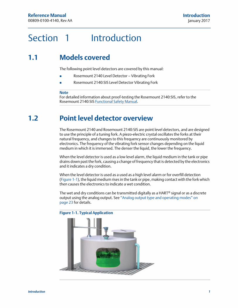
When the level detector is used as a used as a high level alarm or for overfill detection (Figure 1-1), the liquid medium rises in the tank or pipe, making contact with the fork which then causes the electronics to indicate a wet condition.
The wet and dry conditions can be transmitted digitally as a HART® signal or as a discrete output using the analog output. See “Analog output type and operating modes” on page 23 for details.
Figure 1-1. Typical Application
1Introduction

Reference Manual00809-0100-4140, Rev AA
IntroductionJanuary 2017
Major components of the point level detector are the fork and the electronics housing.The electronics housing contains the output electronics board, optional external configuration buttons, and terminal block.
An optional Local Operator Interface (“LOI”) uses a character display (Figure 1-2) to indicate the live output state, diagnostic messages, and menus. There are two rows of characters, with 8 on the upper row and 6 on the lower row. The LOI also comes with two integral buttons (“internal buttons”) for using the menu system.
Figure 1-2. Local Operator Interface (LOI) Display
1.3 Using this manual
The sections in this manual provide information on installing, operating, and maintaining the Rosemount 2140 and Rosemount 2140:SIS Level Detectors (“level detectors”).The sections are organized as follows:
Section 2: Configuration provides instruction on basic and advanced configuration tasks when commissioning and operating the level detectors.
Section 3: Hardware Installation contains mechanical installation instructions.
Section 4: Electrical Installation contains electrical installation instructions.
Section 5: Operation and Maintenance provides information on calibrating and testing.
Section 6: Troubleshooting provides troubleshooting techniques for common operating problems.
Appendix A: Specifications and Reference Data contains specifications, dimension drawings, and ordering information.
Appendix B: Product Certifications contains intrinsic safety approval information.
Appendix C: Field Communicator Menu Tree provides full menu trees to assist with commissioning, operating, and maintenance tasks.
Appendix D: Local Operator Interface provides detailed LOI menu trees to assist with commissioning, operating, and maintenance tasks.
2 Introduction

Reference Manual 00809-0100-4140, Rev AA
IntroductionJanuary 2017
1.4 Product recycling/disposal
Recycling of equipment and packaging should be taken into consideration and disposed of in accordance with local and national legislation/regulations.
3Introduction

Reference Manual00809-0100-4140, Rev AA
IntroductionJanuary 2017
4 Introduction
Reference Manual 00809-0100-4140, Rev AA
ConfigurationJanuary 2017
Section 2 Configuration
2.1 Safety messages
Procedures and instructions in this section may require special precautions to ensure the safety of the personnel performing the operations. Information that raises potential safety
issues is indicated by a warning symbol ( ). Refer to the following safety messages before performing an operation preceded by this symbol.
2.2 Overview
This section provides instructions for using a Field Communicator, AMSTM Device Manager, or Local Operator Interface (LOI) to configure the Rosemount 2140 or Rosemount 2140:SIS Level Detectors.
For convenience, Field Communicator fast key sequences are labeled “Fast keys”.
Full Field Communicator menu trees are in Appendix C: Field Communicator Menu Tree.
Local Operator Interface menu trees are in Appendix D: Local Operator Interface.
Explosions could result in death or serious injury.
Installation of this Rosemount 2140 and Rosemount 2140:SIS Level Detectors (“level detectors”) in an explosive environment must be in accordance with the appropriate local, national, and international standards, codes, and practices.
Please review Appendix B: Product Certifications for any restrictions associated with a safe installation.
Before connecting a Field Communicator in an explosive atmosphere, ensure the instruments in the loop are installed in accordance with intrinsically safe or non-incendive field wiring practices.
In an explosion-proof/flameproof installation, do not remove the level detector covers when power is applied to the unit.
Process leaks may cause harm or result in death.
Install and tighten process connectors before applying pressure.
Electrical shock can result in death or serious injury.
Avoid contact with the leads and terminals. High voltage that may be present on leads can cause electrical shock.
5Configuration
Reference Manual00809-0100-4140, Rev AA
ConfigurationJanuary 2017
2.3 Get started with your preferredconfiguration tool
The Rosemount 2140 Level Detector and Rosemount 2140:SIS Level Detector can easily be configured by using:
Device Description (DD) based systemse.g. AMS Device Manager and the 475 Field Communicator
Local Operator Interface (LOI)
2.3.1 AMS Device Manager
Get the latest Device Description (DD)
The Device Description (DD) is a configuration tool that is developed to assist the user through the configuration tasks. The Rosemount 2140 DD is typically installed together with AMS Device Manager.
To download the latest HART DD, visit the Emerson Process Management Device Install Kit site at Emerson.com/devicefiles
After downloading, add the DD to AMS Device Manager:
1. Close AMS Device Manager.
2. Click the Start button, and then select All Programs > AMS Device Manager > Add Device Type.
3. Browse to the downloaded DD files and select OK.
In the Add Device Type application, select the Help button for more information on how to complete this operation.
Configure the HART® modem interface
Before connecting to the device using a HART modem, the HART modem interface must be configured in AMS Device Manager:
1. Close AMS Device Manager.
2. Click the Start button, and then select All Programs > AMS Device Manager > Network Configuration.
3. Select Add.
4. In the drop down list, select HART modem and select Install.
5. Follow the on-screen instructions.
In the Network Configuration application, select the Help button for more information on how to complete this operation.
6 Configuration
Reference Manual 00809-0100-4140, Rev AA
ConfigurationJanuary 2017
2.3.2 Field Communicator
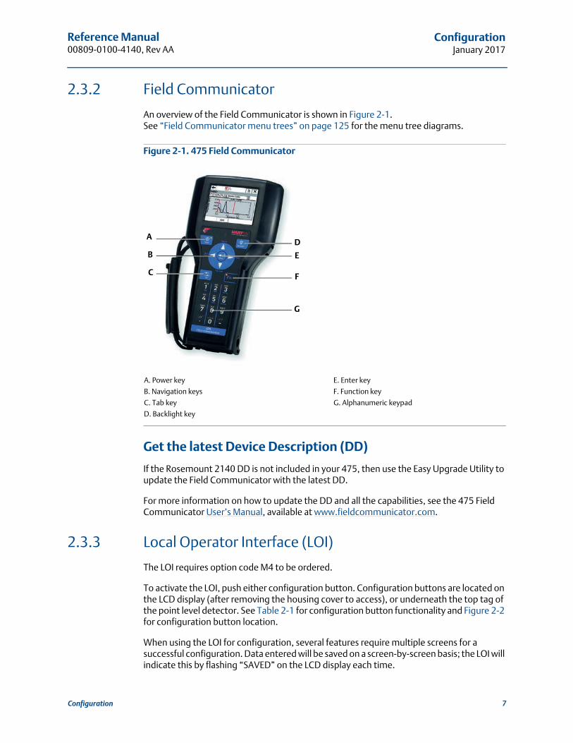
An overview of the Field Communicator is shown in Figure 2-1.See “Field Communicator menu trees” on page 125 for the menu tree diagrams.
Figure 2-1. 475 Field Communicator
A. Power key E. Enter key
B. Navigation keys F. Function key
C. Tab key G. Alphanumeric keypad
D. Backlight key
Get the latest Device Description (DD)
If the Rosemount 2140 DD is not included in your 475, then use the Easy Upgrade Utility to update the Field Communicator with the latest DD.
For more information on how to update the DD and all the capabilities, see the 475 Field Communicator User’s Manual, available at www.fieldcommunicator.com.
2.3.3 Local Operator Interface (LOI)
The LOI requires option code M4 to be ordered.
To activate the LOI, push either configuration button. Configuration buttons are located on the LCD display (after removing the housing cover to access), or underneath the top tag of the point level detector. See Table 2-1 for configuration button functionality and Figure 2-2 for configuration button location.
When using the LOI for configuration, several features require multiple screens for a successful configuration. Data entered will be saved on a screen-by-screen basis; the LOI will indicate this by flashing “SAVED” on the LCD display each time.
A
B
C
D
E
F
G
7Configuration

Reference Manual00809-0100-4140, Rev AA
ConfigurationJanuary 2017
LOI menu trees are available in Appendix D: Local Operator Interface.
Figure 2-2. LOI Configuration Buttons
A. Internal configuration buttons
B. External configuration buttons
Table 2-1. LOI Button Operation
2.4 Switching HART Revision
2.4.1 Switching HART revision with a generic menu
If the HART configuration tool is not capable of communicating with a HART Revision 7 device, it should load a generic menu with limited capability. The following procedures allow for switching between HART Revision 7 and HART Revision 5 from a generic menu.
1. Locate “Message” field.
a. To change to HART Revision 5, enter HART5 and 27 spaces in the message field.
b. To change to HART Revision 7, Enter: HART7 and 27 spaces in the message field.
Button
Left No (SCROLL
Right Yes (ENTER
A
B
8 Configuration
Reference Manual 00809-0100-4140, Rev AA
ConfigurationJanuary 2017
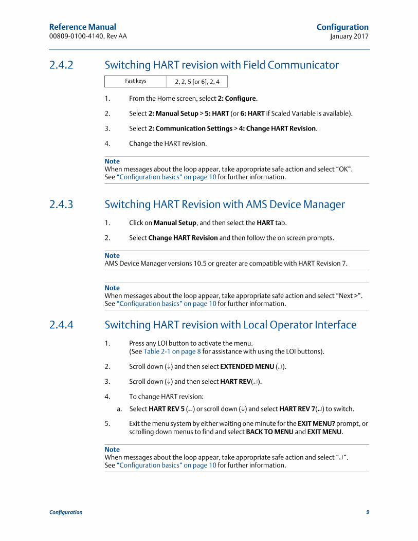
2.4.2 Switching HART revision with Field Communicator
1. From the Home screen, select 2: Configure.
2. Select 2: Manual Setup > 5: HART (or 6: HART if Scaled Variable is available).
3. Select 2: Communication Settings > 4: Change HART Revision.
4. Change the HART revision.
NoteWhen messages about the loop appear, take appropriate safe action and select “OK”. See “Configuration basics” on page 10 for further information.
2.4.3 Switching HART Revision with AMS Device Manager
1. Click on Manual Setup, and then select the HART tab.
2. Select Change HART Revision and then follow the on screen prompts.
NoteAMS Device Manager versions 10.5 or greater are compatible with HART Revision 7.
NoteWhen messages about the loop appear, take appropriate safe action and select “Next >”. See “Configuration basics” on page 10 for further information.
2.4.4 Switching HART revision with Local Operator Interface
1. Press any LOI button to activate the menu.(See Table 2-1 on page 8 for assistance with using the LOI buttons).
2. Scroll down () and then select EXTENDED MENU ().
3. Scroll down () and then select HART REV().
4. To change HART revision:
a. Select HART REV 5 () or scroll down () and select HART REV 7() to switch.
5. Exit the menu system by either waiting one minute for the EXIT MENU? prompt, or scrolling down menus to find and select BACK TO MENU and EXIT MENU.
NoteWhen messages about the loop appear, take appropriate safe action and select “”. See “Configuration basics” on page 10 for further information.
Fast keys 2, 2, 5 [or 6], 2, 4
9Configuration

Reference Manual00809-0100-4140, Rev AA
ConfigurationJanuary 2017
2.5 Configuration basics
The Rosemount 2140 and 2140:SIS Level Detectors (“level detectors”) can be configured before or after installation. Configuring the point level detector before installation ensures all level detector components are in working order before installation.
2.5.1 Setting the security switch
Verify that the security switch is set in the unlock position ( ) to proceed with configuration. See Figure 2-6 on page 43 for the switch location.
2.5.2 Setting the loop to manual
When sending or requesting data that would disrupt the loop or change the point level detector output, set the process application loop to manual control. The Field Communicator, AMS Device Manager, or the LOI prompts you to set the loop to manual when necessary. The prompt is only a reminder. Acknowledging this prompt does not set the loop to manual. It is necessary to set the loop to manual control as a separate operation.
2.6 Configure device using Guided Setup
The options available in the Guided Setup wizard include all items required for basic operation. All basic configuration parameters are described in “Basic setup” on page 14.
2.6.1 Guided setup on the AMS Device Manager
1. Click the Start button, and then select All Programs > AMS Device Manager > AMS Device Manager.
2. Select View > Device Connection View.
3. In the Device Connection View, double-click the HART modem icon.
4. Double-click the device icon.
5. From the Home screen, select Configure > Guided Setup.
6. Select Basic Setup and follow the on-screen instructions.
2.6.2 Guided setup on the Field Communicator
1. Turn on the Field Communicator.
2. From the Main Menu, tap the HART symbol. The Field Communicator now connects to the device.
3. From the Home screen, select Configure > Guided Setup.
4. Select Basic Setup and follow the on-screen instructions.
10 Configuration

Reference Manual 00809-0100-4140, Rev AA
ConfigurationJanuary 2017
2.6.3 Guided setup on the LOI
The Guided Setup wizard is not available on the LOI. Turn to “Basic setup” on page 14 for the LOI instructions to configure basic parameters, and then return here to verify configuration.
2.7 Verify the configuration before installation
It is recommended that various configuration parameters are verified prior to installation into the process. The various parameters are detailed out for each configuration tool.
2.7.1 Verifying configuration (Field Communicator or AMS)
Configuration parameters, listed in Table 2-2, are to be reviewed before the level detector is installed. From the HOME screen of the Field Communicator, enter the fast key sequences listed. Alternatively, turn to the page for detailed instructions.
Table 2-2. Verifying Configuration (Fast Key Sequences)
Parameter
Fast key sequence
HART 7 HART 5
Tag 1, 8, 1, 2 1,8, 1, 1
Model 1, 8, 1, 3 1,8, 1, 3
Primary Variable (page 11) 3, 2, 1, 1 3, 2, 1, 1
Sensor Operating Mode (page 14) 2, 2, 1, 1, 1 2, 2, 1, 1, 1
Sensor Output Delay (page 16) 2, 2, 1, 1, 2 2, 2, 1, 1, 2
Media Density (page 17) 2, 2, 1, 1, 3 2, 2, 1, 1, 3
Sensor Fault Delay (page 22) 2, 2, 1, 3, 2 2, 2, 1, 3, 2
Current Output Type(1) (page 23)
1. Only applicable when the Primary Variable is mapped to the Output State variable.
2, 2, 2, 1, 1 2, 2, 2, 1, 1
Custom Off Current(2) (page 23)
2. Only applicable when Current Output Type is set to “Custom”.
2, 2, 2, 1, 3 2, 2, 2, 1, 3
Custom On Current(2) (page 23) 2, 2, 2, 1, 4 2, 2, 2, 1, 4
Upper Range Value(3) (page 26)
3. Only applicable when the Primary Variable is mapped to the Sensor Frequency or Scaled Variable variables.See “Dynamic variables configuration” on page 13 and “Analog output range points” on page 26 for details.
2, 2, 2, 2, 2 2, 2, 2, 2, 2
Lower Range Value(3) (page 26) 2, 2, 2, 2, 3 2, 2, 2, 2, 3
High Alarm Level(4) (page 33)
4. Alarm level and saturation level indicated depends on the setting of alarm level switch (page 46) and the ordered Alarm Level code (Table A-6 on page 115).
2, 2, 2, 5, 3 2, 2, 2, 5, 3
Low Alarm Level(4) (page 33) 2, 2, 2, 5, 6 2, 2, 2, 5, 6
High Saturation Level(3)(4) (page 33) 2, 2, 2, 5, 4 2, 2, 2, 5, 4
Low Saturation Level(3)(4) (page 33) 2, 2, 2, 5, 5 2, 2, 2, 5, 5
Alarm Switch Position/Direction (page 46) 2, 2, 2, 5, 2 2, 2, 2, 5, 2
11Configuration

Reference Manual00809-0100-4140, Rev AA
ConfigurationJanuary 2017
2.7.2 Verifying configuration (LOI)
1. Press any configuration button to activate the LOI.
2. Select VIEW CONFIG ().
3. Scroll down () to review the following parameters prior to installation:
4. Exit the menu system by either waiting one minute for the EXIT MENU? prompt, or scrolling down menus to find and select BACK TO MENU and EXIT MENU.
TAG
MODEL – e.g. “2140”.
T Range – Operating temperature range (page 115)
EFP – Extended Features Package enabled (Yes/No)
IS PV(1)
1. Only available when the Extended Features Package (EFP) is enabled.
– Primary Variable mapping (page 11)
S UNIT(1) – Secondary Variable units (page 129)
T UNIT(2)
2. SI units only.
– Electronics temperature units (page 30)
OP MODE – Operating mode (page 14).
DENSITY – Media density (page 17).
O DLY – Sensor output delay (page 16).
F DLY – Fault output delay (page 22).
AOMODE(3)
3. Only visible when the Primary Variable (“PV”) is mapped to the Output State variable.
– Analog Output operating mode (page 23)
OFF MA(4)
4. Only visible when the Analog Output operating mode is set to custom.
– Custom mA output for ‘off’ output state (page 23)
ON MA(4) – Custom mA output for ‘on’ output state (page 23)
S-START – Device test (page 73)/proof test (page 75) at start.
URV(5)
5. Only visible when the Primary Variable (“PV”) is mapped to the Sensor Frequency or Scaled Variable variables.
– Upper range value for analog output (page 26)
LRV(5) – Lower range value for analog output (page 26)
DAMPING(1) – Scaled Variable damping (page 28)
HIALRM(6)
6. Alarm level and saturation level indicated depends on the setting of hardware alarm level switch (page 46) and the ordered Alarm Level code (Table A-6 on page 115).
– High alarm level (page 33)
LOALRM(6) – Low alarm level (page 33)
HI SAT(5)(6) – High saturation level (page 33)
LO SAT(5)(6) – Low saturation level (page 33)
ALARM – Alarm switch position/direction (page 46)
SECURE – Security switch position (page 43)
12 Configuration
Reference Manual 00809-0100-4140, Rev AA
ConfigurationJanuary 2017
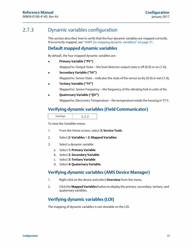
2.7.3 Dynamic variables configuration
This section describes how to verify that the four dynamic variables are mapped correctly.If incorrectly mapped, see “HART (re-mapping dynamic variables)” on page 31.
Default mapped dynamic variables
By default, the four mapped dynamic variables are:
Primary Variable (“PV”)
Mapped to: Output State – the level detector output state is off (0.0) or on (1.0).
Secondary Variable (“SV”)
Mapped to: Sensor State – indicates the state of the sensor as dry (0.0) or wet (1.0).
Tertiary Variable (“TV”)
Mapped to: Sensor Frequency – the frequency of the vibrating fork in units of Hz.
Quaternary Variable (“QV”)
Mapped to: Electronics Temperature – the temperature inside the housing in °F/°C.
Verifying dynamic variables (Field Communicator)
To view the Variables menu:
1. From the Home screen, select 3: Service Tools.
2. Select 2: Variables > 2: Mapped Variables
3. Select a dynamic variable:
a. Select 1: Primary Variable.
b. Select 2: Secondary Variable.
c. Select 3: Tertiary Variable.
d. Select 4: Quaternary Variable.
Verifying dynamic variables (AMS Device Manager)
1. Right click on the device and select Overview from the menu.
2. Click the Mapped Variables button to display the primary, secondary, tertiary, and quaternary variables.
Verifying dynamic variables (LOI)
The mapping of dynamic variables is not viewable on the LOI.
Fast keys 3, 2, 2
13Configuration

Reference Manual00809-0100-4140, Rev AA
ConfigurationJanuary 2017
Optional re-mapping of PV
Versions of the Rosemount 2140 with the Extended Features Package (EFP)can re-map the PV to:
Sensor Frequency
Scaled Variable
Optional re-mapping of SV, TV, or QV
The Rosemount 2140 and Rosemount 2140:SIS can re-map the SV, TV, or QV to:
Output State
Sensor State
Sensor Frequency
Electronics Temperature
Terminal Voltage
Versions of the Rosemount 2140 with the Extended Features Package (EFP)can also re-map the SV, TV, or QV to:
Scaled Variable
NoteSee “HART (re-mapping dynamic variables)” on page 31 for related information.
2.8 Basic setup
2.8.1 Sensor operation mode
The level detector has three operation modes:
Normal (Rosemount 2140 only)
Default mode with no sensor fault detection enabled.
Enhanced wet
Optional mode where the Sensor State device variable is forced to a ‘wet state’ while sensor faults are detected. (Default mode on Rosemount 2140:SIS).
Enhanced dry
Optional mode where the Sensor State device variable is forced to a ‘dry state’ while sensor faults are detected.
NoteSensor State (page 82) is used to derive the Output State (page 13).
Fast keys 2, 2, 1, 1, 1
14 Configuration
Reference Manual 00809-0100-4140, Rev AA
ConfigurationJanuary 2017
To change or view the mode (Field Communicator)
1. From the Home screen, select 2: Configure.
2. Select 2: Manual Setup > 1: Operation > 1: Application.
3. Select 1: Sensor Operation Mode.
4. If changing the mode setting:
a. Select a mode: “Normal”, “Enhanced (Fault=Wet)”, or “Enhanced (Fault=Dry)”.
NoteWhen messages about the loop appear, take appropriate safe action and select “OK”.See “Configuration basics” on page 10 for further information.
To change or view the mode (AMS Device Manager)
1. Right click on the device and select Configure.
2. Select Manual Setup, and then select the Operation tab.
3. If changing the mode setting:
a. Select a mode: “Normal”, “Enhanced (Fault=Wet)”, or “Enhanced (Fault=Dry)” at the Sensor Operation Mode field.
NoteWhen messages about the loop appear, take appropriate safe action and select “Next >”. See “Configuration basics” on page 10 for further information.
To change or view the mode (LOI)
1. Press any LOI button to activate the menu.(See Table 2-1 on page 8 for assistance with using the LOI buttons).
2. If changing the mode setting:
a. Scroll down () and then select EXTENDED MENU ().
b. Scroll down () and then select SENSOR ().
c. Select SENSOR OPMODE ().
d. Follow on-screen instructions to select a new mode:NORM (normal), EN WET (enhanced wet), or EN DRY (enhanced dry).
3. If viewing the mode setting:
a. Select VIEW CONFIG ().
b. Scroll down () until OPMODE and the mode setting appears.
4. Exit the menu system by either waiting one minute for the EXIT MENU? prompt, or scrolling down menus to find and select BACK TO MENU and EXIT MENU.
15Configuration

Reference Manual00809-0100-4140, Rev AA
ConfigurationJanuary 2017
NoteWhen messages about the loop appear, take appropriate safe action and select “”. See “Configuration basics” on page 10 for further information.
2.8.2 Sensor output delay
When there is a detected change in process conditions, from wet-to-dry ordry-to-wet, the Sensor Output Delay variable can action a delay of up to 3600 seconds before the new state change is indicated. The default delay is one second.
Depending on the application, a suitable delay can prevent constant switching of the output state. If, for example, there are waves in a tank, then there may be splashes causing intermittently detected changes in process conditions. The sensor output delay ensures that the fork is dry or wet for a suitable period before switching.
To change or view the delay setting (Field Communicator)
1. From the Home screen, select 2: Configure.
2. Select 2: Manual Setup > 1: Operation > 1: Application.
3. Select 2: Sensor Output Delay.
4. If changing the delay setting:
a. Edit a delay value in the range 0 to 3600 seconds.
NoteWhen messages about the loop appear, take appropriate safe action and select “OK”.See “Configuration basics” on page 10 for further information.
To change or view the delay setting (AMS Device Manager)
1. Right click on the device and select Configure.
2. Select Manual Setup, and then the select the Operation tab.
3. If changing the delay setting:
a. Edit a delay in the range 0 to 3600 seconds at the Sensor Output Delay field.
To change or view the delay setting (LOI)
1. Press any LOI button to activate the menu.(See Table 2-1 on page 8 for assistance with using the LOI buttons).
2. If changing the mode setting:
a. Scroll down () and then select EXTENDED MENU ().
b. Scroll down () and then select SENSOR ().
Fast keys 2, 2, 1, 1, 2
16 Configuration

Reference Manual 00809-0100-4140, Rev AA
ConfigurationJanuary 2017
c. Scroll down () and then select OUTPUT DELAY ().
d. Follow on-screen instructions and edit a new delay setting in the range 0 to 3600. Entering a delay outside this range results in ERROR being displayed.
3. If viewing the mode setting:
a. Select VIEW CONFIG ().
b. Scroll down () until O DELAY and the delay setting appears.
4. Exit the menu system by either waiting one minute for the EXIT MENU? prompt, or scrolling down menus to find and select BACK TO MENU and EXIT MENU.
NoteWhen messages about the loop appear, take appropriate safe action and select “”. See “Configuration basics” on page 10 for further information.
2.8.3 Media density
The measured frequency of the fork, when immersed in process medium, can be affected by liquid density variations. As a result, the dry-to-wet and wet-to-dry switching points are different for all types and varieties of process medium (Figure 2-3 on page 18).
To overcome this, accurate switching points can be calculated by the Rosemount 2140 and Rosemount 2140:SIS after a suitable density band is selected for the process medium.
Media Density options the Rosemount 2140 and Rosemount 2140:SIS are:
0.4 – 0.6 SG (for a 400 to 600 kg/m3 range – e.g. propane)
0.5 – 0.9 SG (for a 500 to 900 kg/m3 range – e.g. alcohol)
0.8 – 1.3 SG (for a 800 to 1300 kg/m3 range – e.g. water) (default selection)
1.2 – 3.0 SG (for a 1200 to 3000 kg/m3 range – e.g. acid)
Extra options on the Rosemount 2140 are:
Low compacted sediment
Medium compacted sediment
High compacted sediment
Extreme compacted sediment
NoteVersions of the Rosemount 2140 and Rosemount 2140:SIS with the Extended Features Package (EFP) can use Media Learn (page 19) to automatically select a density band.For all other versions, keep the default setting for Media Density when the liquid specific gravity is unknown.
Fast keys 2, 2, 1, 1, 3
17Configuration
Reference Manual00809-0100-4140, Rev AA
ConfigurationJanuary 2017
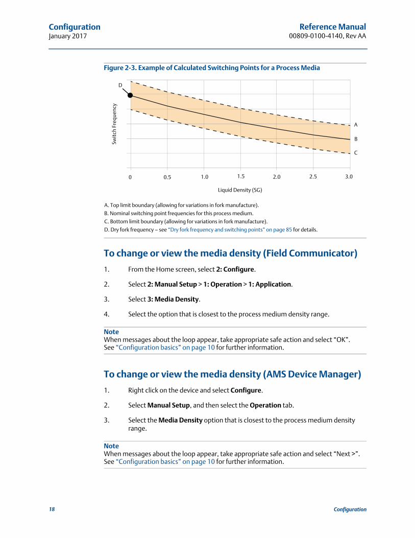
Figure 2-3. Example of Calculated Switching Points for a Process Media
A. Top limit boundary (allowing for variations in fork manufacture).
B. Nominal switching point frequencies for this process medium.
C. Bottom limit boundary (allowing for variations in fork manufacture).
D. Dry fork frequency – see “Dry fork frequency and switching points” on page 85 for details.
To change or view the media density (Field Communicator)
1. From the Home screen, select 2: Configure.
2. Select 2: Manual Setup > 1: Operation > 1: Application.
3. Select 3: Media Density.
4. Select the option that is closest to the process medium density range.
NoteWhen messages about the loop appear, take appropriate safe action and select “OK”.See “Configuration basics” on page 10 for further information.
To change or view the media density (AMS Device Manager)
1. Right click on the device and select Configure.
2. Select Manual Setup, and then select the Operation tab.
3. Select the Media Density option that is closest to the process medium density range.
NoteWhen messages about the loop appear, take appropriate safe action and select “Next >”. See “Configuration basics” on page 10 for further information.
Liquid Density (SG)
0 0.5 1.0 1.5 2.0 2.5 3.0
Swit
ch F
requ
ency
A
B
C
D
18 Configuration

Reference Manual 00809-0100-4140, Rev AA
ConfigurationJanuary 2017
To change or view the media density (LOI)
1. Press any LOI button to activate the menu.(See Table 2-1 on page 8 for assistance with using the LOI buttons).
2. Scroll down () and then select EXTENDED MENU ().
3. Scroll down () and then select MEDIA ().
4. Select DENSITY ().
5. Follow on-screen instructions to select an option that is closest to the process medium density range.
NoteWhen messages about the loop appear, take appropriate safe action and select “”. See “Configuration basics” on page 10 for further information.
2.8.4 Media learn
Versions of the Rosemount 2140 and Rosemount 2140:SIS with the Extended Features Package (EFP) can use the Media Learn function.
Media Learn makes configuring the Media Density variable (page 17) even easier.
This procedure requires the fork tines to be fully immersed in the process medium for a short period to gather the frequency data, calculate the liquid density, and then auto-select the option for the Media Density variable.
NoteMedia Learn may have unexpected results in high temperatures.
Figure 2-4. Fully Immersed Tines for Media Learn
Fast keys 2, 2, 1, 1, 5
OKTines FullyImmersed
19Configuration

Reference Manual00809-0100-4140, Rev AA
ConfigurationJanuary 2017
To use Media Learn (Field Communicator)
1. From the Home screen, select 2: Configure.
2. Select 2: Manual Setup > 1: Operation > 1: Application.
3. Select 5: Media Learn.
4. Follow on-screen instructions until the learning procedure is completed.
NoteWhen messages about the loop appear, take appropriate safe action and select “OK”.See “Configuration basics” on page 10 for further information.
To use Media Learn (AMS Device Manager)
1. Right click on the device and select Configure.
2. Select Manual Setup, and then select the Operation tab.
3. Click on the Media Learn button (in the Application box).
4. Follow on-screen instructions until the learning procedure is completed.(The “Recall Learnt” option restores a previously learnt media density).
5. In the Application box, the Learnt box is now marked.
NoteWhen messages about the loop appear, take appropriate safe action and select “Next >”. See “Configuration basics” on page 10 for further information.
To use Media Learn (LOI)
1. Press any LOI button to activate the menu.(See Table 2-1 on page 8 for assistance with using the LOI buttons).
2. Scroll down () and select EXTENDED MENU ().
3. Scroll down () and select MEDIA ().
4. Scroll down () and select LEARN ().
5. Follow on-screen instructions until the learning procedure is completed.
NoteWhen messages about the loop appear, take appropriate safe action and select “”. See “Configuration basics” on page 10 for further information.
20 Configuration

Reference Manual 00809-0100-4140, Rev AA
ConfigurationJanuary 2017
2.8.5 Allowable change in dry fork frequency
When the level detector is re-calibrated in the field, a comparison is made between the new dry fork frequency and original factory-set Dry Fork Frequency value. If the difference is greater than the allowable change value, the re-calibration is rejected. Check the fork for damage, corrosion, or coating, and clean the fork if necessary before re-trying.
The default setting is 100 Hz, but can be set to a value in the range 0 to 255 Hz.Setting the value to 0 Hz switches off the allowable change monitoring.
NoteFast key sequence is 3, 4, 1, 2, 1 for the original factory-set Dry Fork Frequency.
To change or view the allowable change(Field Communicator)
1. From the Home screen, select 2: Configure.
2. Select 2: Manual Setup > 1: Operation > 3: Sensor.
3. Select 1: Allowable Change In Dry Fork Frequency.
4. Follow the on-screen instructions to configure the allowable change.
NoteWhen messages about the loop appear, take appropriate safe action and select “OK”.See “Configuration basics” on page 10 for further information.
To change or view the allowable change(AMS Device Manager)
1. Right click on the device and select Configure.
2. Select Manual Setup, and then select the Operation tab.
3. If changing the allowable change setting:
a. Edit a frequency in the range 0 to 255 Hz at the Allowable Change In Dry Fork Frequency field.
NoteWhen messages about the loop appear, take appropriate safe action and select “Next >”. See “Configuration basics” on page 10 for further information.
To change or view the allowable change (LOI)
This configuration parameter is not available on the LOI.
Fast keys 2, 2, 1, 3, 1
21Configuration

Reference Manual00809-0100-4140, Rev AA
ConfigurationJanuary 2017
2.8.6 Sensor fault delay
When the level detector is operating in Enhanced Mode and detects a fork sensor fault, Sensor State (page 82) indicates a fault state after a delay.
The default setting is 5 seconds. It can be set to a value in the range 0 to 3600 seconds.
NoteWhen the Rosemount 2140 is operating in Normal mode, a fork sensor fault is not detected and Sensor State continues to indicate a valid state.
To change or view the sensor fault delay(Field Communicator)
1. From the Home screen, select 2: Configure.
2. Select 2: Manual Setup > 1: Operation > 3: Sensor.
3. Select 2: Sensor Fault Delay.
4. Follow the on-screen instructions to configure the delay.
NoteWhen messages about the loop appear, take appropriate safe action and select “OK”.See “Configuration basics” on page 10 for further information.
To change or view the sensor fault delay(AMS Device Manager)
1. Right click on the device and select Configure.
2. Select Manual Setup, and then select the Operation tab.
3. If changing the delay setting:
a. Edit the number of seconds at the Sensor Fault Delay field.
NoteWhen messages about the loop appear, take appropriate safe action and select “Next >”. See “Configuration basics” on page 10 for further information.
To change or view the sensor fault delay (LOI)
1. Press any LOI button to activate the menu.(See Table 2-1 on page 8 for assistance with using the LOI buttons).
2. If changing the mode setting:
a. Scroll down () and then select EXTENDED MENU ().
b. Scroll down () and then select SENSOR ().
Fast keys 2, 2, 1, 3, 2
22 Configuration

Reference Manual 00809-0100-4140, Rev AA
ConfigurationJanuary 2017
c. Scroll down () and then select FAULT DELAY ().
d. Follow on-screen instructions and edit a new delay setting in the range 0 to 3600. Entering a delay outside this range results in ERROR being displayed.
3. If viewing the mode setting:
a. Select VIEW CONFIG ().
b. Scroll down () until F DELAY and the delay setting appears.
4. Exit the menu system by either waiting one minute for the EXIT MENU? prompt, or scrolling down menus to find and select BACK TO MENU and EXIT MENU.
NoteWhen messages about the loop appear, take appropriate safe action and select “”. See “Configuration basics” on page 10 for further information.
2.8.7 Analog output type and operating modes
The analog output is driven by a device variable mapped to the Primary Variable (“PV”). Carefully read displayed warnings that appear before applying changes.
This sub-section is for establishing how the analog output will operate.
Current output type
Options to select are:
4 and 20 mA – i.e. 4mA = ‘off’ and 20 mA = ‘on’ switched output states.
Continue reading this sub-section for related configuration steps.
8 and 16 mA – i.e. 8 mA = ‘off’ and 16 mA = ‘on’ switched output states.
Continue reading this sub-section for related configuration steps.
Custom– i.e. user-set output currents for ‘off’/‘on’ switched output states.
The output current levels for ‘off’ and ‘on’ output states are user-entered under the Custom Off Current and Custom On Current variables. Continue reading this sub-section for related configuration steps.
LEVELTESTER– compatibility mode
See Table 2-3 for output current information.
Table 2-3. LEVELTESTER Output Current
Fast keys 2, 2, 2, 1, 1
Output current Wet on Dry on
Wet 18.5±0.5 mA @ 0.5 Hz 6 mA
Dry 9 mA 13.5±0.5 mA @ 0.5 Hz
23Configuration

Reference Manual00809-0100-4140, Rev AA
ConfigurationJanuary 2017
Current output operating mode
This selects the fork sensor state associated with the Output State device variable indicating ‘on’. Options to select are:
Dry on
Wet on
Custom “off” current
When the Current Output Type is set to “Custom”, this parameter is for entering the output current to be applied when:
The Current Output Operating Mode variable is set to “Dry on”and the fork is immersed in liquid or sand/sediment.
The Current Output Operating Mode variable is set to “Wet on”and the fork is not immersed in liquid or sand/sediment.
Custom “on” current
When the Current Output Type is set to “Custom”, this parameter is for entering the output current to be applied when:
The Current Output Operating Mode variable is set to “Wet on”and the fork is immersed in liquid or sand/sediment.
The Current Output Operating Mode variable is set to “Dry on”and the fork is not immersed in liquid or sand/sediment.
To change current output type and operating mode(Field Communicator)
1. From the Home screen, select 2: Configure.
2. Select 2: Manual Setup > 2: Analog Output > 1: Mode Setup.
3. If changing the current output type:
a. Select 1: Current Output Type.
b. Make the type selection.
c. If the type is set to Custom, enter output current levels in the3: Custom Off Current and 4: Custom On Current screens.
4. If changing the current output operating mode:
a. Select 2: Current Output Operating Mode.
b. Make the mode selection.
Fast keys 2, 2, 2, 1, 2
Fast keys 2, 2, 2, 1, 3
Fast keys 2, 2, 2, 1, 4
24 Configuration

Reference Manual 00809-0100-4140, Rev AA
ConfigurationJanuary 2017
NoteWhen messages about the loop appear, take appropriate safe action and select “OK”.See “Configuration basics” on page 10 for further information.
To change the current output type and operating mode(AMS Device Manager)
1. Right click on the device and select Configure.
2. Select Manual Setup, and then select the Analog Output tab.
3. If changing the current output type:
a. Select an option for the Current Output Type field.
b. If the type selected is Custom, enter output currents for ‘off’/‘on’ output states at the Custom Off Current and Custom On Current fields.
4. If changing the current output operating mode:
a. Select an option for the Current Output Operating Mode field.
5. Click on Send.
6. Carefully read the warning and click Yes if it is safe to apply the changes.
NoteWhen messages about the loop appear, take appropriate safe action.See “Configuration basics” on page 10 for further information.
To change the current output type and operating mode (LOI)
1. Press any LOI button to activate the menu.(See Table 2-1 on page 8 for assistance with using the LOI buttons).
2. If changing the current output type:
a. Scroll down () and then select EXTENDED MENU ().
b. Scroll down () and then select ANALOG OUTPUT ().
c. Scroll down () and then select OUTPUT TYPE ().
d. Follow on-screen instructions and select a current output type(“4 and 20 mA”, “8 and 16 mA”, or “Custom”).
e. If the type selected is “Custom”, enter output currents for ‘off’ and ‘on’ output states at the CUSTOM OFF and CUSTOM ON menus.
3. If changing the current output operating mode:
a. Scroll down () and then select EXTENDED MENU ().
b. Scroll down () and then select ANALOG OUTPUT ().
c. Scroll down () and then select OPERATE MODE ().
d. Follow on-screen instructions and select a current output operating mode(“Wet on” or “Dry on”).
25Configuration

Reference Manual00809-0100-4140, Rev AA
ConfigurationJanuary 2017
NoteWhen messages about the loop appear, take appropriate safe action and select “”. See “Configuration basics” on page 10 for further information.
2.8.8 Analog output range points
The analog output is driven by a device variable mapped to the Primary Variable (“PV”). Carefully read displayed warnings that appear before applying changes.
This section is for entering the range points for the PV to be output using the analog output.
The Lower Range Value (LRV) variable is the PV represented by 4 mA, and the Upper Range Value (URV) variable is the PV represented by 20 mA. This PV range can be a sub-set of the sensor limits defined by Upper PV Limit and Lower PV Limit variables (see Table 2-4 on page 28).
However, by default, the Output State is mapped to the PV. The range points for this are read-only and identical to the associated sensor limits (see “Sensor limits” on page 28).
If supported, Sensor Frequency or Scaled Variable can instead be re-mapped to the PV.The range points then automatically change from read-only to editable, allowing range points to be changed, but are subject to the sensor limits (see “Sensor limits” on page 28).
Optionally, use Scaled Variable Damping (page 28) to smooth out large steps in output current changes when the PV is a scaled variable.
See also “Site calibration of analog output” on page 70 for other related information.
Entering range points (Field Communicator)
1. From the Home screen, select 2: Configure.
2. Select 2: Manual Setup > 2: Analog Output > 2: Set Range Points.
3. Enter the PV value at 20 mA in the 2: Upper Range Value variable.
4. Enter the PV value at 4 mA in the 3: Lower Range Value variable.
NoteAt the 4: Readings menu (2, 2, 2, 4), the 1: Analog Output item indicates the live output current. The 2: Percent of Range item indicates the percentage of that output current in terms of the complete 4–20 mA range. For example, 8 mA is 25% of range, 12 mA is 50%
NoteWhen messages about the loop appear, take appropriate safe action and select “OK”.See “Configuration basics” on page 10 for further information.
Fast keys 2, 2, 2, 2
26 Configuration

Reference Manual 00809-0100-4140, Rev AA
ConfigurationJanuary 2017
Entering range points (AMS Device Manager)
1. Right click on the device and select Configure.
2. Select Manual Setup, and then select the Analog Output tab.
3. Enter the PV at 4 mA in the Lower Range Value field.
4. Enter the PV at 20 mA in the Upper Range Value field.
5. Click Send.
6. Carefully read the warning and click Yes if it is safe to apply the changes.
NoteIn the Readings box, the Analog Output device variable indicates the live output current. The Percent of Range device variable indicates a percentage of that output current in terms of the complete 4–20 mA range. For example, 8 mA is 25% of range, 12 mA is 50%, etc.
NoteWhen messages about the loop appear, take appropriate safe action.See “Configuration basics” on page 10 for further information.
Entering range points (LOI)
1. Press any LOI button to activate the menu.(See Table 2-1 on page 8 for assistance with using the LOI buttons).
2. If changing the range points:
a. Scroll down () and then select RERANGE ().
b. Select ENTER VALUES ().
c. Select LRV ().
d. Follow on-screen instructions and edit a new PV value at 4 mA.(Attempting to enter an invalid value results in ERROR being displayed).
e. Scroll down () and then select URV ().
f. Follow on-screen instructions and edit a new PV value at 20 mA.(Attempting to enter an invalid value results in ERROR being displayed).
3. If viewing the range points:
a. Select VIEW CONFIG ().
b. Scroll down () until LRV and the lower range value setting appears.
c. Scroll down () until URV and the upper range value setting appears.
4. Exit the menu system by either waiting one minute for the EXIT MENU? prompt,or scrolling down menus to find and select BACK TO MENU and EXIT MENU.
NoteWhen messages about the loop appear, take appropriate safe action and select “”. See “Configuration basics” on page 10 for further information.
27Configuration

Reference Manual00809-0100-4140, Rev AA
ConfigurationJanuary 2017
Sensor limits
Table 2-4 shows the sensor limits applied when a device variable is mapped to the PV dynamic variable. They are used for scaling gauges in a Host system (e.g. AMS Device Manager) and for validating the range points in the analog output (page 26).
NoteSee also “Dynamic variables configuration” on page 13 for related information.
Table 2-4. Sensor Limits for Device Variables
2.8.9 Scaled Variable damping
Damping is an optional parameter for changing the response time of the level detector when the PV is mapped to the Scaled Variable. Increasing the damping value can smooth wide variations in the output caused by rapid input changes, but at the cost of decreasing response times.
Damping settings range from 0.0 to 60.0 seconds. An appropriate damping setting is a balance of the necessary response time, signal stability, and other requirements of the loop dynamics within your system.
Carefully read displayed warnings that appear before applying changes.
NoteVersions of the Rosemount 2140 with the Extended Features Package (EFP) can re-map the PV to Scaled Variable.
Damping with a Field Communicator
1. From the Home screen, select 2: Configure.
2. Select 2: Manual Setup > 2: Analog Output > 2: Set Range Points.
3. Select 4: Damping.
4. Enter the damping setting.
Device Variables Lower PV Limit Upper PV Limit
Output State 0.0 1.0
Sensor State 0.0 1.0
Sensor Frequency 250.0 Hz 1800.0 Hz
Electronics Temperature –40 °C 85 °C
Terminal Voltage 10.5 V 42.4 V
Scaled Variable Defined by sensor frequency limits and scaling data.
Fast keys 2, 2, 2, 2, 4
28 Configuration

Reference Manual 00809-0100-4140, Rev AA
ConfigurationJanuary 2017
NoteWhen messages about the loop appear, take appropriate safe action.See “Configuration basics” on page 10 for further information.
Damping with AMS Device Manager
1. Right click on the device and select Configure.
2. Select Manual Setup, and then select the Analog Output tab.
3. Enter the damping setting, and click Send.
4. Carefully read the warning and click Yes if it is safe to apply the changes.
Damping with a LOI
1. Press any LOI button to activate the menu.(See Table 2-1 on page 8 for assistance with using the LOI buttons).
2. If changing the damping setting:
a. Scroll down () and then select EXTENDED MENU ().
b. Scroll down () and then select DAMPING ().
c. Follow on-screen instructions and edit a new damping setting in the range 0 to 60. Attempting to enter a value outside this range results in ERROR being displayed.
If viewing the damping setting:
a. Select VIEW CONFIG ().
b. Scroll down () until DAMPING and the damping setting appears.
3. Exit the menu system by either waiting one minute for the EXIT MENU? prompt, or scrolling down menus to find and select BACK TO MENU and EXIT TO MENU.
2.9 Local Operator Interface (LOI) display
The LOI display configuration allows customization of the displayed information to suit application requirements. The LOI alternates between selected items.
NoteThe LOI can also be configured to display configuration information during the device startup. Select Review Parameters at Startup to enable this functionality.
Fast keys 2, 2, 2
Output State (page 13) Electronics Temperature (page 13)
Sensor State (page 13) Terminal Voltage (page 13)
Sensor Frequency (page 13) Percent of Range (page 26)
Scaled Variable(1) (page 13)
1. This is selectable only if the Rosemount 2140 has the Extended Features Package enabled.
Analog Output (page 26)
29Configuration
Reference Manual00809-0100-4140, Rev AA
ConfigurationJanuary 2017
Configuring LOI display (using Field Communicator)
1. From the Home screen, select 2: Configure.
2. Select 2: Manual Setup > 5: Display.
3. For items 1 to 8, select or de-select the parameters to show on the LOI display. Optionally, select 9: Review Parameters at Startup.
Configuring LOI display (using AMS Device Manager)
1. Right click on the device and select Configure.
2. Click Manual Setup, and then select the Display tab.
3. Select or de-select the parameters to show on the LOI display, and then click Send.
4. Optionally, select Review Parameters at Startup.
Configuring LOI display (using LOI)
1. Press any LOI button to activate the menu.(See Table 2-1 on page 8 for assistance with using the LOI buttons).
2. Scroll down () and then select DISPLAY ().
3. Scroll down (), and then for each item:
a. Use the select () to change the setting to ON or OFF
b. Answer YES () to confirm the change or NO () to abandon the change.
4. Exit the menu system by either waiting one minute for the EXIT MENU? prompt, or scrolling down menus to find and select BACK TO MENU and EXIT TO MENU.
2.9.1 Electronics temperature units
NoteAvailable on SI units only.
Changing temperature units (Field Communicator)
1. From the Home screen, select 2: Configure.
2. Select 2: Manual Setup > 4: Device Temperature > 3: Units.
3. Select the measurement units.
NoteWhen messages about the loop appear, take appropriate safe action and select “OK”.See “Configuration basics” on page 10 for further information.
Fast keys 2, 2, 4, 3
30 Configuration

Reference Manual 00809-0100-4140, Rev AA
ConfigurationJanuary 2017
Changing temperature units (AMS Device Manager)
1. Right click on the device and select Configure.
2. Select Manual Setup, and then select the Device Temperature tab.
3. Select the measurement units at the Setup Unit box, and click Send.
NoteWhen messages about the loop appear, take appropriate safe action.See “Configuration basics” on page 10 for further information.
Changing temperature units (LOI)
1. Press any LOI button to activate the menu.(See Table 2-1 on page 8 for assistance with using the LOI buttons).
2. Scroll down () and then select UNITS ().
3. Select DEG C or scroll down () and select DEG F ().
4. Exit the menu system by either waiting one minute for the EXIT MENU? prompt, or scrolling down menus to find and select BACK TO MENU and EXIT MENU.
NoteWhen messages about the loop appear, take appropriate safe action and select “”. See “Configuration basics” on page 10 for further information.
2.10 Detailed setup
2.10.1 HART (re-mapping dynamic variables)
The re-mapping of process variables to the primary, secondary, tertiary, and quaternary variables (“PV”, “SV”, “TV”, and “QV” respectively) can be performed here, if supported. See “Dynamic variables configuration” on page 13 to find out what is supported.
The PV can be re-mapped with a Field Communicator, AMS Device Manager, or a LOI. However, the other three variables (SV, TV, and QV) can only be re-mapped using a Field Communicator or the AMS Device Manager.
NoteThe process variable assigned to the PV drives the analog output. See “Analog output type and operating modes” on page 23 for further information.
31Configuration
Reference Manual00809-0100-4140, Rev AA
ConfigurationJanuary 2017
Re-mapping process variables (Field Communicator)
1. From the Home screen, select 2: Configure.
2. Select 2: Manual Setup > 5: (or 6:) HART.
3. Select 1: Variable Mapping.
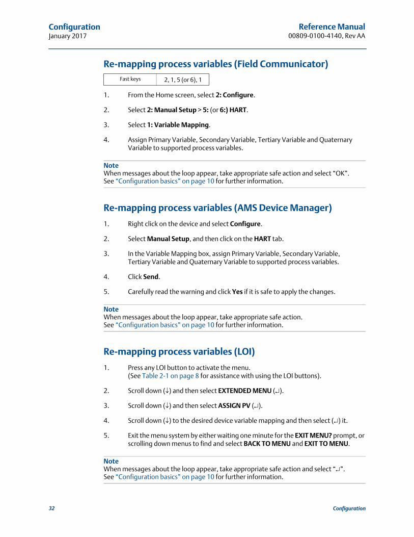
4. Assign Primary Variable, Secondary Variable, Tertiary Variable and Quaternary Variable to supported process variables.
NoteWhen messages about the loop appear, take appropriate safe action and select “OK”.See “Configuration basics” on page 10 for further information.
Re-mapping process variables (AMS Device Manager)
1. Right click on the device and select Configure.
2. Select Manual Setup, and then click on the HART tab.
3. In the Variable Mapping box, assign Primary Variable, Secondary Variable,Tertiary Variable and Quaternary Variable to supported process variables.
4. Click Send.
5. Carefully read the warning and click Yes if it is safe to apply the changes.
NoteWhen messages about the loop appear, take appropriate safe action.See “Configuration basics” on page 10 for further information.
Re-mapping process variables (LOI)
1. Press any LOI button to activate the menu.(See Table 2-1 on page 8 for assistance with using the LOI buttons).
2. Scroll down () and then select EXTENDED MENU ().
3. Scroll down () and then select ASSIGN PV ().
4. Scroll down () to the desired device variable mapping and then select () it.
5. Exit the menu system by either waiting one minute for the EXIT MENU? prompt, or scrolling down menus to find and select BACK TO MENU and EXIT TO MENU.
NoteWhen messages about the loop appear, take appropriate safe action and select “”. See “Configuration basics” on page 10 for further information.
Fast keys 2, 1, 5 (or 6), 1
32 Configuration

Reference Manual 00809-0100-4140, Rev AA
ConfigurationJanuary 2017
2.10.2 Configuring alarm and saturation levels
NoteThis function is available only when the Primary Variable (”PV”) is mapped to the Sensor Frequency or Scaled Variable device variables.
The Rosemount 2140 continuously performs self-diagnostic routines. When there is a device malfunction that is an alarm condition, the Analog Output current is driven to a configured alarm level (see tables) based on the HI or LO alarm switch position (see “Setting the alarm switch” on page 46) and the ordered Alarm Level code.
In normal operation, the Analog Output current is driven in response to fork frequency changes. If the fork frequency goes outside sensor limits (see Table 2-4 on page 28), or if the output current would be beyond the saturation points (see tables), the current is limited to a saturation level based on the alarm switch position and the ordered Alarm Level code.
Table 2-5. Rosemount Alarm and Saturation Values (Alarm Level code C8)
Table 2-6. NAMUR-Compliant Alarm and Saturation Values (Alarm Level codes C4/C5)
Table 2-7. Custom Alarm and Saturation Values (Alarm Level code C1)
Failure mode alarm and saturation levels can be custom-configured using a Field Communicator, AMS Device Manager, or the Local Operator Interface (LOI).The following limitations exist for custom-configurable levels:
Low alarm level must be less than the low saturation level.
High alarm level must be higher than the high saturation level.
Alarm and saturation levels must be separated by at least 0.1 mA.
The configuration tool will provide an error message if the configuration rule is violated.
NoteWhen set to HART multi-drop mode, all saturation and alarm information is sent digitally; saturation and alarm conditions will not affect the analog output.See also “Establishing multi-drop communications (optional)” on page 40.
Level 4–20 mA saturation 4–20 mA alarm
Low (LO position) 3.9 mA 3.75 mA
High (HI position) 20.8 mA 21.75 mA
Level 4–20 mA saturation 4–20 mA alarm
Low (LO position) 3.8 mA 3.6 mA
High (HI position) 20.5 mA 22.5 mA
Level 4–20 mA saturation 4–20 mA alarm
Low (LO position) 3.7 mA to 3.9 mA 3.6 mA to 3.8 mA
High (HI position) 20.1 mA to 22.9 mA 20.2 mA -to 23.0 mA
33Configuration

Reference Manual00809-0100-4140, Rev AA
ConfigurationJanuary 2017
To change or view alarm and saturation levels(Field Communicator)
1. From the Home screen, select 2: Configure.
2. Select 2: Manual Setup > 2: Analog Output > 5: Alarm/Saturation Levels.
3. Select 7: Config Alarm/Sat Levels.
4. Follow prompts to configure alarm and saturation levels. (See Table 2-5, Table 2-6, and Table 2-7 for reference).
NoteWhen messages about the loop appear, take appropriate safe action and select “OK”.See “Configuration basics” on page 10 for further information.
To change or view alarm and saturation levels(AMS Device Manager)
1. Right click on the device, and select Configure.
2. Select Manual Setup, and then select Analog Output tab.
3. Click on the Configure Alarm and Saturation Levels button.
4. Follow screen prompts to configure Alarm and Saturation Levels.(See Table 2-5, Table 2-6, and Table 2-7 for reference).
NoteWhen messages about the loop appear, take appropriate safe action.See “Configuration basics” on page 10 for further information.
To change or view alarm and saturation levels (LOI)
1. Press any LOI button to activate the menu.(See Table 2-1 on page 8 for assistance with using the LOI buttons).
2. If changing the alarm and saturation levels setting:
a. Scroll down () and then select EXTENDED MENU ().
b. Scroll down () and then select ALRM SAT VALUES ().
c. Scroll down () to the desired option (“ROSEMOUNT VALUES”, “NAMUR VALUES” or “CUSTOM VALUES”) and then select () it.
d. Follow screen prompts to configure Alarm and Saturation Levels.(See Table 2-5, Table 2-6, and Table 2-7 for reference).
3. If viewing the alarm and saturation levels:
Fast keys 2, 2, 2, 5, 7
34 Configuration

Reference Manual 00809-0100-4140, Rev AA
ConfigurationJanuary 2017
a. Select VIEW CONFIG ().
b. Scroll down () until HI SAT and the high saturation level setting appears.
c. Scroll down () until LO SAT and the high saturation level setting appears.
4. Exit the menu system by either waiting one minute for the EXIT MENU? prompt, or scrolling down menus to find and select BACK TO MENU and EXIT TO MENU.
NoteWhen messages about the loop appear, take appropriate safe action and select “”. See “Configuration basics” on page 10 for further information.
2.10.3 Configuring process alerts
NoteThis function is available only a Rosemount 2140 and Rosemount 2140:SIS with the Extended Features Package enabled.
Process alerts allow the level detector to indicate when a pre-set data point is exceeded. Alerts can be set for the following device variables:
Output State
Sensor State
Sensor Frequency
Scaled Variable (if supported)
Terminal Voltage
Electronics Temperature
An active alert is displayed on a Field Communicator, AMS Device Manager status screen or in the error section of an LOI display. When the value returns within range, an alert is reset.
Alerts are configured by:
Alert Mode – Select “on” to enable the alert, or “off” to disable it.
High Value Alert – Defines the upper boundary limit for a device variable value.
Low Value Alert – Defines the lower boundary limit for a device variable value.
NoteThe high alert value must be higher than the low alert value. Both alert values must also be within the sensor limits.
35Configuration

Reference Manual00809-0100-4140, Rev AA
ConfigurationJanuary 2017
Configuring process alerts (Field Communicator)
1. From the Home screen, select 2: Configure.
2. Select 3: Alert Setup.
3. Select a device variable e.g. Output State.
4. Select 1: Configure Alert.
5. Follow screen prompts to configure the alert.
Configuring process alerts (AMS Device Manager)
1. Right click on the device and select Configure.
2. Select Guided Setup, and then click the Process Alerts button.
3. Follow screen prompts to configure Process Alerts.
Configuring process alerts (LOI)
This function is not configurable on the Local Operator Interface.
2.10.4 Configuring Scaled Variable
NoteThe Scaled Variable function is available if the Rosemount 2140 has the Extended Features Package (EFP) enabled.
The Scaled Variable function allows custom units to be displayed on the LOI display and drive the 4-20 mA output.
If custom units are to drive the 4-20 mA analog output, Scaled Variable must be re-mapped as the primary variable. See “Configuring burst mode (optional)” on page 38.
The Scaled Variable configuration defines the following items:
Scaled Variable units
– Enter the custom unit description to be displayed.
Scaled data options
– Select the transfer function for the application: Linear or discrete.
Frequency value position 1
– Enter the lower known value point (with consideration of linear offset).
Scaled Variable value position 1
– Enter the custom unit (equivalent to the lower known value point).
Fast keys 2, 3
36 Configuration

Reference Manual 00809-0100-4140, Rev AA
ConfigurationJanuary 2017
Frequency value position 2
– Enter the upper known value point.
Scaled Variable value position 2
– Enter the custom unit (equivalent to the upper known value point).
Linear offset
– The value required to zero out fork frequency effecting the desired fork frequency reading.
Configuring Scaled Variable (Field Communicator)
1. From the Home screen, select 2: Configure.
2. Select 1: Guided Setup, and then 3: (or 4:) Scaled Variable.
3. Follow the screen prompts to configure the Scaled Variable function.
NoteWhen messages about the loop appear, take appropriate safe action and select “OK”.See “Configuration basics” on page 10 for further information.
Configuring Scaled Variable (AMS Device Manager)
1. Right click on the device and, select Configure.
2. Select the Scaled Variable tab and click the Scaled Variable button.
3. Follow the prompts to configure the Scaled Variable function.
NoteWhen messages about the loop appear, take appropriate safe action.See “Configuration basics” on page 10 for further information.
Configuring Scaled Variable (LOI)
1. Press any LOI button to activate the menu.(See Table 2-1 on page 8 for assistance with using the LOI buttons).
2. Scroll down () and then select EXTENDED MENU ().
3. Scroll down () and then select SCALED VARIAB ().
4. Scroll down () and then select CONFIG SCALED ().
5. Follow the prompts to configure the Scaled Variable function.
NoteWhen messages about the loop appear, take appropriate safe action and select “”. See “Configuration basics” on page 10 for further information.
Fast keys 2, 1, 4
37Configuration

Reference Manual00809-0100-4140, Rev AA
ConfigurationJanuary 2017
2.11 Configuring burst mode (optional)
Burst mode is compatible with the analog output signal. Due to the way that HART protocol features simultaneous digital and analog data transmission, the analog value can drive other equipment in the loop while the control system is receiving the digital information.
Burst mode applies only to the transmission of dynamic variables (PV, SV, TV, and QV), and does not affect the way other data is accessed. However, when activated, burst mode can slow down communication of non-dynamic variable data to the host by 50%.
Access to information other than dynamic variables is obtained through the normal poll/response method of HART communication. A Field Communicator, AMS Device Manager or the control system may request any of the information that is normally available while the level detector is in burst mode. Between each message sent by the level detector, a short pause allows the Field Communicator, AMS Device Manager or a control system to initiate a request.
Choosing burst mode options in HART 5
Message content options:
PV only
Percent of Range
PV, SV, TV, and QV
Process Variables
Device Status
Choosing burst mode options in HART 7
Message content options:
PV only
Percent of Range
PV, SV, TV, and QV
Process Variables and Status
Process Variables
Device Status
Choosing a HART 7 Trigger Mode
When in HART 7 mode, the following trigger modes can be selected.
Continuous (same as HART5 burst mode)
Rising
Falling
Windowed
On Change
Fast keys 2, 2, 5 or 6, 3
38 Configuration

Reference Manual 00809-0100-4140, Rev AA
ConfigurationJanuary 2017
NoteConsult your host system manufacturer for burst mode requirements.
Configuring burst mode (Field Communicator)
1. From the Home screen, select 2: Configure.
2. Select 2: Manual Setup > (5: or 6:) HART. > 3: Burst Mode Configuration.
3. Configure Burst Message 1.
a. Select Burst Message 1 and choose Enabled.
b. Select Message 1 Content and choose an option e.g. “PV, SV, TV, and QV”.
4. Optionally configure Burst Message 2 and Burst Message 3.
NoteWhen messages about the loop appear, take appropriate safe action.See “Configuration basics” on page 10 for further information.
NoteBurst Message 1 will burst at a continuous rate of 0.5 s.Alternatively, use the guided setup for configuring burst mode (fast keys 2, 1, 5).
Configuring burst mode (AMS Device Manager)
1. Right click on the device and select Configure.
2. Select Manual Setup and click on the HART tab.
3. Configure Burst Message 1 in the Burst Mode Configuration box.
a. Select “Enabled” for Burst Message 1.
b. Select an option e.g. “PV, SV, TV, and QV” for Message 1 Content.
4. Optional click on the Configure Additional Messages button to configureBurst Message 2 and Burst Message 3.
a. Select the message content e.g. “PV Only”.
b. Select the trigger mode e.g. “Rising”, and then the trigger level and update rate.
NoteBurst Message 1 will burst at a continuous rate of 0.5 s.Alternatively, use the guided setup for configuring burst mode.
39Configuration

Reference Manual00809-0100-4140, Rev AA
ConfigurationJanuary 2017
2.12 System readiness If using HART based control or asset management systems, confirm the HART
capability of such systems prior to commissioning and installation. Not all systems are capable of communicating with HART revision 7 devices.
For instructions on how to change the HART revision of your point level detector, see “Switching HART Revision” on page 8.
Verify the latest Device Driver (DD/DTM) is loaded on your systems to ensure proper communications.
2.12.1 Confirm correct Device Driver (DD)
1. Download the latest DD from Emerson.com (or www.hartcomm.org).
2. In the Browse by Member drop-down menu, select Rosemount business unit of Emerson Process Management.
3. Select Rosemount 2140.
2.13 Establishing multi-drop communications (optional)
Multi-dropping refers to the connection of several devices to a single communications transmission line. Communication between the host device and another device takes place digitally with the analog output of the level detector deactivated.
Multi-drop installation requires consideration of the update rate necessary from each device, the combination of different device types, and the length of the transmission line. Communication with devices can be accomplished with HART modems and a host implementing the HART protocol. Each device is identified by a unique address and responds to the commands defined in the HART protocol.
Field Communicators and AMS Device Manager can test, configure, and format a multi-dropped device the same way as a device in a standard point-to-point installation.
Figure 2-5 shows a typical multi-drop network.
NoteA multi-drop device in HART Revision 7 mode has a fixed analog output of 4 mA for all but one device. Only one device is allowed to have an active analog signal.
40 Configuration

Reference Manual 00809-0100-4140, Rev AA
ConfigurationJanuary 2017
Figure 2-5. Typical Multi-drop Network
A. HART modem
B. Power supply
The Rosemount 2140 and Rosemount 2140:SIS are set to address zero (0) at the factory, which allows operation in the standard point-to-point manner with a 4–20 mA output signal.
To activate multi-drop communication, the level detector address must be changed to a number from 1 to 15 for HART Revision 5, or 1 to 63 for HART Revision 7. This change deactivates the 4–20 mA analog output, sending it to 4 mA. It also disables the failure mode alarm signal, which is controlled by the upscale/downscale switch position.Failure signals in multi-dropped devices are communicated through HART messages.
2.13.1 Communicating with a multi-dropped level detector
To communicate with a multi-drop level detector, the Field Communicator or AMS Device Manager has to be set up for polling.
Communicating with a multi-dropped device(Field Communicator)
1. Select Utility and Configure HART Application.
2. Select Polling Addresses, and then enter 0 to 63.
Communicating with a multi-dropped device(AMS Device Manager)
Click on the HART modem icon and select Scan All Devices.
A.
B.
41Configuration

Reference Manual00809-0100-4140, Rev AA
ConfigurationJanuary 2017
2.13.2 Changing a level detector polling address
To activate multi-drop communication, the Rosemount 2140 or Rosemount 2140:SIS poll address must be assigned a unique number from 1 to 15 for HART 5, or 1 to 63 for HART 7.Each device in a multi-dropped loop must have a unique poll address.
Changing the polling address (Field Communicator)
1. From the Home screen, select 2: Configure.
2. Select 2: Manual Setup > 6: HART > 2: Communication Settings.
3. Change the polling address.
a. In HART 5 mode, enter a polling address in the 1: Polling Address screen.
b. In HART 7 mode, enter a polling address in the 2: Change Polling Address screen.
Changing the polling address (AMS Device Manager)
1. Right click on the device and select Configure.
2. In HART 5 mode:
a. Click on Manual Setup, select the HART tab.
b. In the Communication Settings box, enter a new polling address and click Send.
3. In HART 7 mode:
a. Click on Manual Setup, and then select the HART tab.
b. Click the Change Polling Address button.
4. Carefully read the warning and click Yes if it is safe to apply the changes.
2.14 Configuring level detector security
There are four security methods with the Rosemount 2140 and Rosemount 2140:SIS.
Security switch
HART Lock
Configuration buttons lock
LOI password
Fast keys 2, 2, 5 or 6, 2, 2
42 Configuration

Reference Manual 00809-0100-4140, Rev AA
ConfigurationJanuary 2017
Figure 2-6. Alarm and Security Switches
A. Alarm switch
B. Security switch
2.14.1 Setting the security switch
The security switch is used to prevent changes to the configuration data.Figure 2-6 indicates the security switch location.
If the security switch is set to the locked location ( ), any configuration requests made using HART, LOI, or local configuration buttons are rejected and the configuration data will not be modified.
Enabling the security switch (lock position)
1. Set process loop to manual and remove power.
2. Remove the housing cover.
3. Use a small screwdriver to slide the security switch to the lock ( ) position.
4. Replace the housing cover.
5. The cover must be fully engaged to comply with explosion-proof requirements.
Viewing the security switch status (Field Communicator)
1. From the Home screen, select 3: Service Tools.
2. Select 4: Maintenance > 6: Security.
3. Select 1: Security Switch Status.
Viewing the security switch status (AMS device Manager)
1. Right click on the device and select Service Tools.
2. Select Maintenance, and then select the Security tab.
3. The Security Switch Status is in the Hardware box.
Without LOI display With LOI display
A
B
43Configuration
Reference Manual00809-0100-4140, Rev AA
ConfigurationJanuary 2017
Viewing the security switch status (LOI)
1. Press any configuration button to activate the LOI.(See Table 2-1 on page 8 for assistance with using the LOI buttons).
2. Select VIEW CONFIG ().
3. Scroll down () until SECURE and the status is displayed.
4. Exit the menu system by either waiting one minute for the EXIT MENU? prompt, or scrolling down the menus to find and select BACK TO MENU and EXIT TO MENU.
2.14.2 HART Lock
The HART Lock prevents changes to the configuration data from all sources.
The HART Lock can only be set using HART communication, and is only available in HART Revision 7 mode. The HART Lock can be enabled or disabled with a Field Communicator orAMS Device Manager.
Configuring HART Lock (Field Communicator)
1. From the Home screen, select 2: Configure.
2. Select 2: Manual Setup. > 6: Security (or 7: Security if Scaled Variable is available).
3. Select 4: HART Lock.
4. Select the Lock or Unlock option.
Configuring HART Lock (AMS device Manager)
1. Right click on the device and select Configure.
2. Select Manual Setup, and then select the Security tab.
3. Click on the Lock/Unlock button in HART Lock (Software) box.
4. Follow the screen prompts to lock or unlock.
2.14.3 Configuration button lock
The configuration button lock disables all local button functionality. Changes to the configuration using the LOI and local buttons will be rejected. Local external buttons can be locked using HART communication only.
Fast keys 2, 2, 6 [or 7], 4
Fast keys 2, 2, 6 [or 7], 3
44 Configuration

Reference Manual 00809-0100-4140, Rev AA
ConfigurationJanuary 2017
Configuring the configuration button lock(Field Communicator)
1. From the Home screen, select 2: Configure.
2. Select 2: Manual Setup > 6: Security (or 7: Security if Scaled Variable is available).
3. Select 3: Configuration Buttons.
4. Select the Disable option to lock, or the Enabled option to unlock.
Configuring the configuration button lock(AMS device Manager)
1. Right click on the device and select Configure.
2. Select Manual Setup, and then select the Security tab.
3. Within the Configuration Buttons drop-down menu, select Disabled to lock the external local buttons or Enabled to unlock.
4. Click Send.
5. Confirm service reason and click Yes.
2.14.4 Local Operator Interface (LOI) password
A Local Operator Interface password can be entered and enabled to prevent review and modification of device configuration using the LOI.
This password protection does not prevent configuration from HART or external buttons.A LOI password is a 4-digit code that is to be set by the user.
LOI password protection can be configured and enabled/disabled by HART communication using a Field Communicator, AMS Device Manager, or the LOI.
Configuring LOI password (Field Communicator)
1. From the Home screen, select 2: Configure.
2. Select 2: Manual Setup. > 6: Security (or 7: Security if Scaled Variable is available).
3. Select 5: LOI Password Protection.
4. Select the Enabled option.
5. Enter a 4-digit number as the password.
Fast keys 2, 2, 6 [or 7], 5
45Configuration

Reference Manual00809-0100-4140, Rev AA
ConfigurationJanuary 2017
Configuring LOI password (AMS Device Manager)
1. Right click on the device and select Configure.
2. Select Manual Setup, and then select the Security tab.
3. Within the Local Operator Interface box, click the Configure Password button.
4. Follow the screen prompts:
a. Enable the LOI password protection.
b. Enter a 4-digit number as the password.
Configuring LOI password (using Local Operator Interface)
1. Press any LOI button to activate the menu.(See Table 2-1 on page 8 for assistance with using the LOI buttons).
2. Scroll down () and then select EXTENDED MENU ().
3. Scroll down () and then select PASSWORD ().
4. Enable the LOI password protection.
5. Enter a 4-digit number as the password.
6. Exit the menu system by either waiting one minute for the EXIT MENU? prompt, or scrolling down the menus to find and select BACK TO MENU and EXIT TO MENU.
2.15 Setting the alarm switch
On the electronics board is an alarm switch (see Figure 2-6 on page 43).Follow the steps below to configure the alarm switch.
1. Set process loop to manual and remove power.
2. Remove the housing cover.
3. Use a small screwdriver to slide the alarm switch to desired position.
4. Replace the housing cover.
5. The cover must be fully engaged to comply with explosion-proof requirements.
46 Configuration
Reference Manual 00809-0100-4140, Rev AA
Hardware InstallationJanuary 2017
Section 3 Hardware Installation
3.1 Safety messages
Procedures and instructions in this section may require special precautions to ensure the safety of the personnel performing the operation. Information that raises potential safety issues is indicated by a warning symbol ( ). The external hot surface symbol ( ) is used when a surface is hot and care must be taken to avoid possible burns. If there is a risk of an electrical shock, the ( ) symbol is used. Refer to the following safety messages before performing an operation preceded by this symbol.
Failure to follow these installation guidelines could result in death or serious injury.
The Rosemount 2140 Level Detector and Rosemount 2140:SIS Level Detector (“level detectors”) must be installed, connected, commissioned, operated, and maintained by suitably qualified personnel only, observing any national and local requirements that may apply.
Ensure the wiring is suitable for the electrical current and the insulation is suitable for the voltage, temperature, and environment.
Use the equipment only as specified in this manual. Failure to do so may impair the protection provided by the equipment.
Any substitution of non-recognized parts may jeopardize safety and is under no circumstances allowed.
The weight of a level detector with a heavy flange and extended fork length may exceed 37 lb. (18 kg). A risk assessment is required before carrying, lifting, and installing the level detector.
Failure to comply with the following requirements will result in the invalidation of the product safety certification.
Check for risk of process medium build-up on the level switch forks.Avoid situations where drying and coating products may create an excessive build-up (see Figure 3-3 on page 51) or implement preventative maintenance programs to ensure the build-up is not enough to impair performance.
Ensure there is no risk of 'bridging' the level switch forks. Examples of products that create 'bridging' of the forks are dense paper slurries and bitumen.
Explosions could result in death or serious injury.
Installation of this level detector in a hazardous area environment must be in accordance with the appropriate local, national, and international standards, codes, and practices.
Please review Appendix B: Product Certifications for restrictions associated with hazardous area installation.
Before connecting a Field Communicator in an explosive atmosphere, ensure the instruments in the loop are installed in accordance with intrinsically safe or non-incendive field wiring practices.
In an explosion-proof/flameproof installation, do not remove the level detector covers when power is applied to the unit.
47Hardware Installation

Reference Manual00809-0100-4140, Rev AA
Hardware InstallationJanuary 2017
3.2 Considerations before installation
ImportantEmerson is not in a position to evaluate or guarantee the compatibility of the process fluid or other process parameters with the product, options, configuration or materials of construction selected.
3.2.1 Safety considerations
Control drawings for hazardous area installations are in Appendix B: Product Certifications, and there are safety instructions in the Rosemount 2140 Product Certifications Manual(see Emerson.com/Rosemount for other language versions).
3.2.2 Environmental considerations
The Rosemount 2140 Level Detector and Rosemount 2140:SIS Level Detector are wired point level detectors, and are available as Intrinsically Safe (IS) or explosion-proof/flame-proof versions for hazardous area installations. There are also ordinary location versions for unclassified, safe areas. Approvals are listed in Appendix B: Product Certifications of this manual.
These level detectors are designed for open or closed tanks, and pipe installation. It is weatherproof and protected against the ingress of dust, but must be protected from flooding. Avoid installing the level detector near heat sources.
External surface may be hot.
Care must be taken to avoid possible burns.
Process leaks may cause harm or result in death.
Install and tighten process connectors before applying pressure.
Do not attempt to loosen or remove process connectors while a level detector is in service.
Electrical shock can result in death or serious injury.
If the level detector is installed in a high voltage environment and a fault condition or installation error occurs, high voltage may be present on leads and terminals.
Use extreme caution when making contact with the leads and terminals.
Make sure that power to the level detector is off while making connections.
Replacement equipment or spare parts not approved by Emerson for use as spare parts could reduce the pressure retaining capabilities of the level detector and may render the instrument dangerous.
Use only spare parts supplied or sold by Emerson.
48 Hardware Installation

Reference Manual 00809-0100-4140, Rev AA
Hardware InstallationJanuary 2017
Figure 3-1. Environmental Considerations
3.2.3 Application considerations
For most liquids, including coating, aerated liquids and slurries, the function is virtually unaffected by flow, turbulence, bubbles, foam, vibration, solid particles, build-up, or properties of the liquid.
The Rosemount 2140 and 2140:SIS Level Detectors (“level detectors”) are available as Intrinsically Safe (IS) or explosion-proof/flameproof versions for hazardous area installations. There are also ordinary location versions for unclassified, safe areas.
The level detectors can be mounted in an open or closed tank, or a pipe. There is a wide range of threaded, flanged, and hygienic process connection options.
Supported process temperature ranges are dependent on the selected Operating Temperature code in the model number.
2140****M is the mid range option: -40 °F (-40 °C) to 356 °F (180 °C)
2140****E is the high range option: -94 °F (-70 °C) to 500 °F (260 °C)
If applicable, see also Appendix B: Product Certifications for the process temperature range limits required to comply with hazardous area product approvals.
OKOK
49Hardware Installation

Reference Manual00809-0100-4140, Rev AA
Hardware InstallationJanuary 2017
Application limits Check for risk of process medium build-up on the level switch forks.
Avoid situations where a drying and coating process medium may create an excessive build-up (see Figure 3-3 on page 51) or implement preventative maintenance programs to ensure the build-up is not enough to impair performance.
Ensure there is no risk of ‘bridging’ the level switch forks. Examples of products that can create ‘bridging’ of forks are dense paper slurries and bitumen.
Problems may occur if product coats and dries causing caking.
Ensure the process is operating within the instrument operating temperature and pressure ranges (see “Specifications” on page 103).
Ensure the liquid viscosity is within the recommended viscosity range(see “Specifications” on page 103).
Check that the liquid density is higher than 0.4 SG (400 kg/m3)(see “Specifications” on page 103).
Liquid density affects the switch-point e.g. dry-to-wet (see Figure 3-2 on page 50).
The Rosemount 2140 and 2140:SIS are normally insensitive to foams (i.e. they do not see the foam). However, on rare occasions, some very dense foams may be seen as liquid; known examples of this are found in ice-cream and orange juice manufacturing.
Figure 3-2. Level Detection Switching Point
SP: Switching point (H20)
HY: Switching point hysteresis
SP
HYSP
0.1 in.(2.5 mm)
0.5 in.(13 mm)
0.5 in.(13 mm)
50 Hardware Installation

Reference Manual 00809-0100-4140, Rev AA
Hardware InstallationJanuary 2017
NoteWhen mounted vertically, a low density process medium has a switching point closer to the process connection. A high density process medium has a switching point closer to fork tip.
Figure 3-3. Avoid Product Build-up
3.2.4 Installation considerations
Measurement accuracy is dependent upon the proper installation of the level detector.Keep in mind the need for easy access, personnel safety, practical field calibration, and a suitable environment for the level detector.
For dimensional drawings, see “Dimensional drawings” on page 106.
Device identification
To identify the Rosemount 2140 version, see the labels on the housing.
Electronics housing clearances
Mount the level detector in a position to allow easy access to the terminals.
Provide 0.75 in. (19 mm) of clearance for a standard cover to be removed. If an LCD display is installed, provide 3 in. (76.2 mm) of clearance for the extended cover to be removed.
For dimensional drawings, see “Dimensional drawings” on page 106.
Covers installation
Always ensure a proper seal by installing the electronics housing covers so that metal contacts metal. Use Rosemount O-rings.
OK
51Hardware Installation

Reference Manual00809-0100-4140, Rev AA
Hardware InstallationJanuary 2017
Grounding
Always ground the housing in accordance with national and local electrical codes.
The most effective grounding method for the housing is a direct connection to earth ground with minimal impedance. Housings have an external earth ground point for making this connection.
Adjust display rotation
To rotate the housing (Figure 3-4), perform the following procedure:
1. Loosen the set screw until the level detector housing can rotate smoothly.
a. Do not unscrew all the way. Rotating the housing, without this screw in place, can damage the internal wiring.
2. First, rotate the housing clockwise to the desired location.
a. If the desired location cannot be achieved due to the internal thread limit, rotate the housing counterclockwise
3. Re-tighten the set screw.
Figure 3-4. Housing Rotation
How to handle the Rosemount 2140
The weight of the level detector with a heavy flange and extended fork length may exceed37 lb. (18 kg). A risk assessment is required before carrying, lifting, and installing the Rosemount 2140.
Use both hands to carry the level detector, and do not hold using the forks (Figure 3-5).
H3/32 in.Torque 30 in-lb (3 Nm)
Do not attempt to rotate the display beyond the thread limits.
52 Hardware Installation

Reference Manual 00809-0100-4140, Rev AA
Hardware InstallationJanuary 2017
Figure 3-5. Handling the Rosemount 2140
Do not change the Rosemount 2140 in any way
Figure 3-6. Do Not Change the Rosemount 2140
OK
53Hardware Installation

Reference Manual00809-0100-4140, Rev AA
Hardware InstallationJanuary 2017
Installation recommendations
Avoid installing near to liquid entering the tank at the fill point.
Avoid heavy splashing on the forks.
Increasing the sensor output delay reduces accidental switching caused by splashing (see “Sensor output delay” on page 16).
Ensure that the forks do not come into contact with the tank wall, any internal fittings, or obstructions.
Ensure there is sufficient distance between build-up on the tank wall and the fork(see Figure 3-3 on page 51).
Ensure the installation does not create tank crevices around the forks where liquid may collect. This can happen with high-viscosity and high-density liquids.
Extra consideration is needed if the plant vibration is close to the 1400 Hz. operating frequency of the Rosemount 2140.
Supporting the fork extension tube avoids long fork length vibration(see Figure 3-7 on page 55).
54 Hardware Installation

Reference Manual 00809-0100-4140, Rev AA
Hardware InstallationJanuary 2017
Figure 3-7. Required Supports for Extended Fork
OK
OK
OK
OK
3.28 ft. (1.0 m)3.28 ft. (1.0 m)
Maximum3.28 ft.(1.0 m)
3.28 ft. (1.0 m)
3.28 ft. (1.0 m)
Maximum 3.28 ft. (1.0 m)
55Hardware Installation
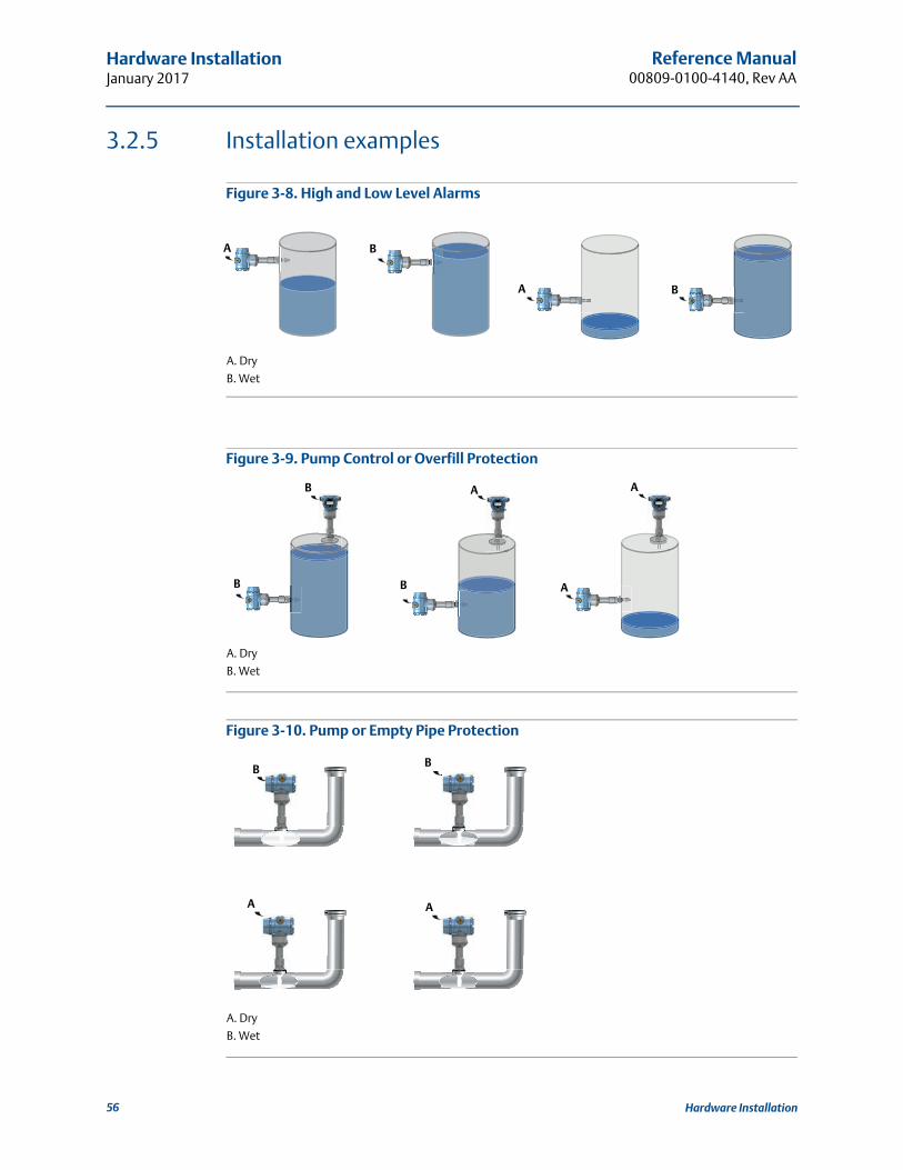
Reference Manual00809-0100-4140, Rev AA
Hardware InstallationJanuary 2017
3.2.5 Installation examples
Figure 3-8. High and Low Level Alarms
A. Dry
B. Wet
Figure 3-9. Pump Control or Overfill Protection
A. Dry
B. Wet
Figure 3-10. Pump or Empty Pipe Protection
A. Dry
B. Wet
A B
A B
B B
B A A
A
A
BB
A
56 Hardware Installation
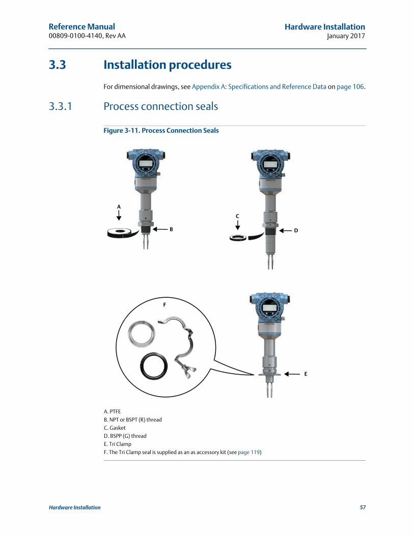
Reference Manual 00809-0100-4140, Rev AA
Hardware InstallationJanuary 2017
3.3 Installation procedures
For dimensional drawings, see Appendix A: Specifications and Reference Data on page 106.
3.3.1 Process connection seals
Figure 3-11. Process Connection Seals
A. PTFE
B. NPT or BSPT (R) thread
C. Gasket
D. BSPP (G) thread
E. Tri Clamp
F. The Tri Clamp seal is supplied as an as accessory kit (see page 119)
A
C
B D
E
F
57Hardware Installation

Reference Manual00809-0100-4140, Rev AA
Hardware InstallationJanuary 2017
3.3.2 Correct fork alignment
Ensure the fork is correctly aligned by using the notches and grooves as indicated in Figure 3-12.
Figure 3-12. Correct Fork Alignment
A. Alignment groove on standard length Rosemount 2140
B. Alignment notch on flanged Rosemount 2140
C. Alignment notch on extended length Rosemount 2140
Pipe installation
Figure 3-13. Pipe Installation
A
BC
OK
58 Hardware Installation

Reference Manual 00809-0100-4140, Rev AA
Hardware InstallationJanuary 2017
Tank installation
Figure 3-14. Tank Installation
OKOK
OK
OK OK
OK
59Hardware Installation

Reference Manual00809-0100-4140, Rev AA
Hardware InstallationJanuary 2017
3.3.3 Tightening the threaded Rosemount 2140
Figure 3-15. Tightening the Threaded Rosemount 2140
3.3.4 Insulation
Figure 3-16. Insulation
A. 3.9 in. (100 mm) clearance all around
B. ROCKWOOL®
OK
A
B
A
60 Hardware Installation

Reference Manual 00809-0100-4140, Rev AA
Electrical InstallationJanuary 2017
Section 4 Electrical Installation
4.1 Safety messages
Procedures and instructions in this section may require special precautions to ensure the safety of the personnel performing the operations. Information that raises potential safety issues is indicated by a warning symbol ( ). Refer to the following safety messages before performing an operation preceded by this symbol.
Explosions could result in death or serious injury.
Installation of Rosemount 2140 and 2140:SIS Level Detectors (“level detectors”) in an explosive environment must be in accordance with the appropriate local, national, and international standards, codes, and practices.
Please review Appendix B: Product Certifications for any restrictions associated with a safe installation.
Before connecting a Field Communicator in an explosive atmosphere, ensure the instruments in the loop are installed in accordance with intrinsically safe or non-incendive field wiring practices.
In an explosion-proof/flameproof installation, do not remove the level detector covers when power is applied to the unit.
Covers are not to be removed in extreme environmental conditions. The internals must be kept free from moisture and conductive dust.
Process leaks may cause harm or result in death.
Install and tighten process connectors before applying pressure.
Electrical shock can result in death or serious injury.
Avoid contact with the leads and terminals. High voltage that may be present on leads can cause electrical shock.
Make sure all electrical installation is in accordance with national and local code requirements.
Do not run signal wiring in conduit or open trays with power wiring or near heavy electrical equipment.
For explosion-proof and ordinary locations installations in accordance with the National Electrical Code, ANSI/NFPA 70 or the Canadian Electrical Code, C22.1., the Rosemount 2140 is to be supplied by a Class 2 or Limited Energy Source.
61Electrical Installation

Reference Manual00809-0100-4140, Rev AA
Electrical InstallationJanuary 2017
4.2 Cable selection
Wiring should be adequately rated and not be susceptible to mechanical damage. Electrical conduit is commonly used to protect wiring. The wiring to this device must maintain creepage(1) and clearance distances. Therefore, the conductors stripping length should be no greater than 6 mm and be free from stray strands.
Use shielded twisted pairs to get the best results. To ensure proper communications, use24 AWG, to a maximum of 14 AWG, and do not exceed 5000 ft. (1500 m). Cable length is limited by the selection of monitoring resistance and wire gauge.
All power to the level detector is supplied over the signal wiring. Signal wiring does not need to be shielded, but use twisted pairs for best results. Do not run unshielded signal wiring in conduit or open trays with power wiring, or near heavy electrical equipment. For high EMI/RFI environments, shielded twisted pair cable should be used.
4.3 Cable gland/conduit
For explosion-proof/flameproof installations, only use cable glands/conduit entry devices certified as explosion-proof/flameproof. For ordinary location installations, use suitably rated cable glands to maintain the IP rating.
Un-used conduit entries must be sealed with a suitably rated blanking plug.See “Conduit entries” on page 103 for all other details.
4.4 Power supply
Terminals in the housing provide connections for signal wiring.
Rosemount 2140 and Rosemount 2140:SIS Level Detectors (“level detectors”) operate with the following power supplies:
10.5 to 42.4 Vdc (10.5 to 30 Vdc in Intrinsically Safe installations).
For HART communication, a minimum loop resistance of 250 is required. Maximum loop resistance is determined by the voltage level of the external power supply (Figure 4-1).
Figure 4-1. Load Limitation
Maximum Loop Resistance = 43.5 * (External Power Supply Voltage – 10.5)
Voltage (Vdc)
Load
(s)
OperatingRegion
1387
1000
500
010.5 20 30
42.4
62 Electrical Installation

Reference Manual 00809-0100-4140, Rev AA
Electrical InstallationJanuary 2017
4.5 Hazardous areas
When the level detector is installed in hazardous areas, local regulations and specifications in applicable certificates must be observed.
4.6 Wiring diagram
Figure 4-2. 4-20 mA/HART® Communication
A. Field Communicator (IS approved for intrinsically safe installations)
B. Approved IS barrier (for intrinsically safe installations only)
C. HART modem
D. Load resistance (250)
E. Current meter
F. Power supply
4.7 Grounding
Always ground the housing in accordance with national and local electrical codes. Failure to do so may impair the protection provided by the equipment.
Do not connect the power signal wiring to the test terminals.Incorrect wiring can damage the test circuit.
-+-
+
Fn1 2 34 5 67 8 90 -
.
A
BD
E
F
C
63Electrical Installation

Reference Manual00809-0100-4140, Rev AA
Electrical InstallationJanuary 2017
4.7.1 Level switch grounding
The most effective grounding method is a direct connection to earth ground with minimal impedance (< 1). Figure 4-3 on page 64 shows the two grounding screw connections provided on the level detector.
NoteGrounding the level detector using a threaded conduit connection may not provide a sufficient ground.
Figure 4-3. Ground Screws
A. External ground screw
B. Internal ground screw
4.7.2 Signal cable shield grounding
Make sure the instrument cable shield is:
trimmed close and insulated from touching the level detector housing.
continuously connected throughout the segment.
connected to a good earth ground at the power supply end.
Figure 4-4. Cable Shield
A. Trim shield and insulate C. Trim shield
B. Minimize distance D. Connect shield back to power supply ground
BA
A
B
B
CC D
64 Electrical Installation

Reference Manual 00809-0100-4140, Rev AA
Electrical InstallationJanuary 2017
4.7.3 Transient protection terminal block grounding
The level detector can withstand electrical transients of the energy level usually encountered in static discharges or induced switching transients. However, high-energy transients, such as those induced in wiring from nearby lightning strikes, can damage the level detector.
A transient protection terminal block can be ordered as an installed option (code T1). The lightning bolt symbol in identifies the transient protection terminal block.
NoteThe transient protection terminal block does not provide transient protection unless the housing is properly grounded.
4.8 Wiring and power-up
1. Verify the power supply is disconnected.
2. Remove the field terminals cover.
In an explosion-proof/flameproof installation, do not remove the level detector covers when power is applied to the unit. Covers are also not to be removed in extreme environmental conditions.
3. Remove the plastic plugs
65Electrical Installation

Reference Manual00809-0100-4140, Rev AA
Electrical InstallationJanuary 2017
4. Pull the cable through the cable gland/conduit.
5. Connect the cable wires (see also Figure 4-2 on page 63).
6. Ensure proper grounding (see “Grounding” on page 63).
7. Tighten the cable gland.
Apply PTFE tape or other sealant to the threads.
½-14 NPT M20 x 1.5
M20(No marking)
Identification of thread size and type
Torque 7 in-lb (0.8 Nm)
66 Electrical Installation
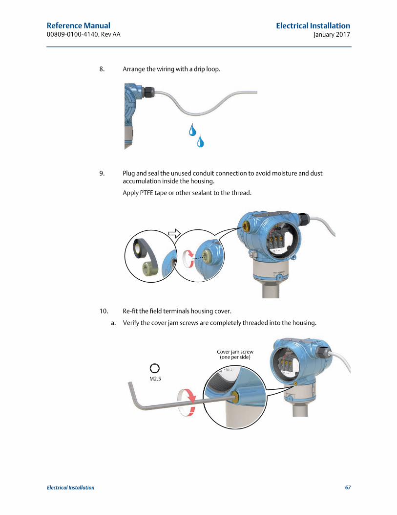
Reference Manual 00809-0100-4140, Rev AA
Electrical InstallationJanuary 2017
8. Arrange the wiring with a drip loop.
9. Plug and seal the unused conduit connection to avoid moisture and dust accumulation inside the housing.
Apply PTFE tape or other sealant to the thread.
10. Re-fit the field terminals housing cover.
a. Verify the cover jam screws are completely threaded into the housing.
M2.5
Cover jam screw(one per side)
67Electrical Installation

Reference Manual00809-0100-4140, Rev AA
Electrical InstallationJanuary 2017
b. Attach and tighten the covers. Make sure the covers are fully engaged.
11. Required for explosion-proof/flameproof installations only:
The cover must be fully engaged to comply with explosion-proof requirements.
a. Turn the cover jam screw counterclockwise until it contacts the cover.
b. Turn the jam screw an extra 1/2 turn counterclockwise to secure the cover.
12. Connect the power supply.
M2.5
Verify that the covers cannot be removed.
68 Electrical Installation

Reference Manual 00809-0100-4140, Rev AA
Operation and MaintenanceJanuary 2017
Section 5 Operation and Maintenance
5.1 Overview
This section contains information on calibrating and testing the Rosemount 2140 and Rosemount 2140:SIS. Field Communicator, AMS, and Local Operator Interface (LOI) instructions are given to perform configuration functions.
5.2 Safety messages
Procedures and instructions in this section may require special precautions to ensure the safety of the personnel performing the operations. Information that raises potential safety
issues is indicated by a warning symbol ( ). Refer to the following safety messages before performing an operation preceded by this symbol.
Explosions could result in death or serious injury.
Installation of this Rosemount 2140 and 2140:SIS Level Detector (“level detectors”) in an explosive environment must be in accordance with the appropriate local, national, and international standards, codes, and practices.
Please review Appendix B: Product Certifications for any restrictions associated with a safe installation.
Before connecting a Field Communicator in an explosive atmosphere, ensure the instruments in the loop are installed in accordance with intrinsically safe or non-incendive field wiring practices.
In an explosion-proof/flameproof installation, do not remove the level detector covers when power is applied to the unit.
Process leaks may cause harm or result in death.
Install and tighten process connectors before applying pressure.
Electrical shock can result in death or serious injury.
Avoid contact with the leads and terminals. High voltage that may be present on leads can cause electrical shock.
69Operation and Maintenance

Reference Manual00809-0100-4140, Rev AA
Operation and MaintenanceJanuary 2017
5.3 Analog output calibration
The analog output can be calibrated to match the user's measurement system. The Analog Output Trim (4-20mA Output Trim) will calibrate the loop at the 4 mA and 20 mA points.
5.3.1 Trimming the analog output
The Analog Output Trim commands allow you to adjust the level detector’s current output at the 4 and 20 mA points to match the plant standards. This trim is performed after the digital to analog conversion so only the 4-20mA analog signal will be affected. Figure 5-1 graphically shows the two ways the characterization curve is affected when an analog output trim is performed.
Figure 5-1. Analog Output Trim Example
A. Before trimB. After Trim
NoteIf a resistor is added to the loop, ensure that the power supply is sufficient to power the level detector to a 20 mA output with additional loop resistance. Refer to “Power supply” on page 62.
5.3.2 Site calibration of analog output
This command starts the on-site calibration of the analog output. It should only be performed by authorized persons.
NoteA reference meter (ammeter) is a required for measuring the actual output current at 4 mA and 20 mA. See “Wiring diagram” on page 63 for the analog output connections.
Fast Keys 3, 4, 4, 2
A A
BB
mA output mA output
70 Operation and Maintenance
Reference Manual 00809-0100-4140, Rev AA
Operation and MaintenanceJanuary 2017
To start the on-site calibration (Field Communicator)
1. From the Home screen, select 3: Service Tools.
2. Select 4: Maintenance > 4: Calibrate Analog.
3. Select 2: Calibrate.
4. Follow on-screen instructions to perform the calibration of 4 mA and 20 mA.
NoteIn the Calibrate Analog menu, the 4: Analog Output option indicates the live output current output and the 5: Percent Range option indicates the percentage of that output current in terms of the complete 4–20 mA range. For example, 8 mA is 25% of range, 12 mA is 50%, etc.
NoteWhen messages about the loop appear, take appropriate safe action and select “OK”.See “Configuration basics” on page 10 for further information.
To start the on-site calibration (AMS Device Manager)
1. Right click on the device and select Service Tools.
2. Select Maintenance, and then select the Calibrate Analog tab.
3. Click on the Calibrate button in the Analog box.
4. Follow on-screen instructions to perform the calibration of 4 mA and 20 mA.
NoteThe Analog Output device variable indicates the live output current output, and the Percent of Range device variable indicates the percentage of that output current in terms of the complete 4–20 mA range. For example, 8 mA is 25% of range, 12 mA is 50%, etc.
NoteWhen messages about the loop appear, take appropriate safe action.See “Configuration basics” on page 10 for further information.
71Operation and Maintenance
Reference Manual00809-0100-4140, Rev AA
Operation and MaintenanceJanuary 2017
To start the on-site calibration (using LOI)
1. Press any LOI button to activate the menu.(See Table 2-1 on page 8 for assistance with using the LOI buttons).
2. Scroll down () and then select EXTENDED MENU ().
3. Select CALIBRATE ().
4. Scroll down () and then select ANALOG TRIM ().
5. Follow on-screen instructions to perform the calibration of 4 mA and 20 mA.
6. Exit the menu system by either waiting one minute for the EXIT MENU? prompt, or scrolling down the menus to find and select BACK TO MENU and EXIT TO MENU.
NoteWhen messages about the loop appear, take appropriate safe action and select “”. See “Configuration basics” on page 10 for further information.
5.3.3 Restoring factory calibration of the analog output
The Recall Factory Trim—Analog Output command allows the restoration of the as-shipped factory settings of the analog output trim. This command can be useful for recovering from an inadvertent trim, incorrect Plant Standard or faulty meter. It is accessible after a site calibration has been performed, but should only be performed by authorized persons.
To restore the factory calibration (Field Communicator)
1. From the Home screen, select 3: Service Tools.
2. Select 4: Maintenance > 4: Calibrate Analog.
3. Select 3: Restore Factory Calibration.
4. Follow on-screen instructions to restore the calibration.
NoteA Restore Site Calibration command becomes available afterwards.
NoteWhen messages about the loop appear, take appropriate safe action and select “OK”.See “Configuration basics” on page 10 for further information.
Fast Keys 3, 4, 4, 3
72 Operation and Maintenance

Reference Manual 00809-0100-4140, Rev AA
Operation and MaintenanceJanuary 2017
To restore the factory calibration (AMS Device Manager)
1. Right click on the device and select Service Tools.
2. Select Maintenance, and then select the Calibrate Analog tab.
3. Click on the Restore Factory Calibration in the Analog box.
4. Follow on-screen instructions to restore the calibration.
NoteA Restore Site Calibration command becomes available afterwards.
NoteWhen messages about the loop appear, take appropriate safe action.See “Configuration basics” on page 10 for further information.
To restore the factory calibration (LOI)
1. Press any LOI button to activate the menu.(See Table 2-1 on page 8 for assistance with using the LOI buttons).
2. Scroll down () and then select EXTENDED MENU ().
3. Select CALIBRATE ().
4. Scroll down () and then select PARAMETR RECALL ().
5. Scroll down () and then select ANALOG RECALL ().
6. Follow on-screen instructions to restore the calibration.
7. Exit the menu system by either waiting one minute for the EXIT MENU? prompt, or scrolling down the menus to find and select BACK TO MENU and EXIT TO MENU.
NoteWhen messages about the loop appear, take appropriate safe action and select “”. See “Configuration basics” on page 10 for further information.
5.4 Performing tests and simulations
5.4.1 Device tests (partial proof test)
The Rosemount 2140 Level Detector (“level detector”) has device-testing functionality. Checks include:
Critical RAM
Program ROM
Configuration storage non-volatile memory
Device supply voltage
73Operation and Maintenance
Reference Manual00809-0100-4140, Rev AA
Operation and MaintenanceJanuary 2017
The level detector can be configured to exercise the analog output to produce the currents representing the lower and upper range values (page 26) and alarm current (page 33).
If the level detector has the Extended Features Package (EFP) and the Scaled Variable or Sensor Frequency is assigned to the PV, the analogue output is also exercised from the low saturation level to the high saturation level (page 33).
By default, the device-testing sequence is not started at every power-up. It can be started by an operator through the LOI menu system i.e. TEST > DEVICE TEST or, when no LOI is not fitted, by using an optional single external push-button fitted to the top of the level detector (underneath the movable nameplate).
There are optional settings to configure:
Duration of the whole testing sequence (each phase takes an equal division of that total time).
Enable/disable device-testing at start-up.
To change device-test parameters (Field Communicator)
1. From the Home screen, select 2: Configure.
2. Select 2: Manual Setup > 1: Operation > 2: Device Test.
3. Choose the device-test parameter to change:
a. Select 1: Duration for setting how long the device-test lasts.
b. Select 2: Start-up Device-Test for setting if device-testing at start-up is enabled/disabled.
NoteWhen messages about the loop appear, take appropriate safe action and select “OK”.See “Configuration basics” on page 10 for further information.
To change device-test parameters (AMS Device Manager)
1. Right click on the device and select Configure.
2. Select Manual Setup, and then select the Operation tab.
3. Edit the Duration field if changing the setting for how long the device-test lasts.
4. Select enabled or disabled at the Start-up Device Test field.
NoteWhen messages about the loop appear, take appropriate safe action.See “Configuration basics” on page 10 for further information.
74 Operation and Maintenance
Reference Manual 00809-0100-4140, Rev AA
Operation and MaintenanceJanuary 2017
To change device-test parameters (LOI)
1. Press any LOI button to activate the menu.(See Table 2-1 on page 8 for assistance with using the LOI buttons).
2. Scroll down () and then select EXTENDED MENU ().
3. Scroll down () and then select DEVICE TEST ().
4. Choose the device-test parameter to change:
c. Select DURATION for setting how long the test lasts.
d. Select START-UP for setting if device-testing at start-up is enabled/disabled.
5. Exit the menu system by either waiting one minute for the EXIT MENU? prompt, or scrolling down the menus to find and select BACK TO MENU and EXIT TO MENU.
NoteWhen messages about the loop appear, take appropriate safe action and select “”. See “Configuration basics” on page 10 for further information.
5.4.2 Proof tests
The Rosemount 2140:SIS must be tested at regular intervals to detect any failures not automatically detected by the device self-test at start-up and the continuous fork sensor diagnostics when operating in Enhanced mode (page 14).
For full information about proof testing the Rosemount 2140:SIS, refer to the Functional Safety Manual.
5.4.3 Verifying alarm level (optional)
If the electronics board, sensor module, or LOI display is repaired or replaced, verify the alarm current level before returning the level detector to service. This is useful in testing the reaction of the control system to a level detector in an alarm state. Thus ensuring the control system recognizes the alarm when activated.
To verify alarm values, run an analog loop test with the simulate alarm option selected (page 76). Ensure that the alarm switch is in the required high or low position (page 46).
NoteBefore returning to service, verify the security switch is set to the correct position. Refer to “Setting the security switch” on page 43.
75Operation and Maintenance

Reference Manual00809-0100-4140, Rev AA
Operation and MaintenanceJanuary 2017
5.4.4 Analog loop test (optional)
This test verifies the analog output of the level detector, the integrity of the loop, and the operations of any recorders or similar devices installed in the loop.
It is recommended that the 4-20 mA points, in addition to alarm levels, are verified when installing, repairing, or replacing a level detector.
The host system may provide a current measurement for the 4-20 mA HART output. If not, connect a reference meter (ammeter) to the level detector by either connecting the meter to the test terminals on the terminal block, or shunting level detector power through the meter at some point in the loop.
This loop test simulation temporarily overrides the analog output with a fixed level of current. Options are:
4 mA
20 mA
Simulate alarm
Other (custom mA)
NoteSimulations are canceled by exiting a screen. They also be cleared by a power re-cycle or device reset. See “Configuring alarm and saturation levels” on page 33 to review output current levels for alarms.
To start the loop test (Field Communicator)
1. From the Home screen, select 3: Service Tools.
2. Select 5: Simulate > 1: Loop Test.
3. Select from the loop test options (e.g. 4 mA) to start the simulation.
NoteWhen messages about the loop appear, take appropriate safe action and select “OK”.See “Configuration basics” on page 10 for further information.
To start the loop test (AMS Device Manager)
1. Right click on the device and select Service Tools.
2. Select Simulate.
3. Click on Loop Test.
4. Follow on-screen instructions to select a loop test and start the simulation.
Fast Keys 3, 5, 1
76 Operation and Maintenance
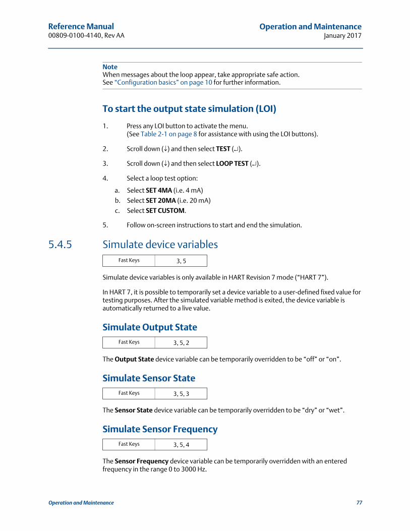
Reference Manual 00809-0100-4140, Rev AA
Operation and MaintenanceJanuary 2017
NoteWhen messages about the loop appear, take appropriate safe action.See “Configuration basics” on page 10 for further information.
To start the output state simulation (LOI)
1. Press any LOI button to activate the menu.(See Table 2-1 on page 8 for assistance with using the LOI buttons).
2. Scroll down () and then select TEST ().
3. Scroll down () and then select LOOP TEST ().
4. Select a loop test option:
a. Select SET 4MA (i.e. 4 mA)
b. Select SET 20MA (i.e. 20 mA)
c. Select SET CUSTOM.
5. Follow on-screen instructions to start and end the simulation.
5.4.5 Simulate device variables
Simulate device variables is only available in HART Revision 7 mode (“HART 7”).
In HART 7, it is possible to temporarily set a device variable to a user-defined fixed value for testing purposes. After the simulated variable method is exited, the device variable is automatically returned to a live value.
Simulate Output State
The Output State device variable can be temporarily overridden to be “off” or “on”.
Simulate Sensor State
The Sensor State device variable can be temporarily overridden to be “dry” or “wet”.
Simulate Sensor Frequency
The Sensor Frequency device variable can be temporarily overridden with an entered frequency in the range 0 to 3000 Hz.
Fast Keys 3, 5
Fast Keys 3, 5, 2
Fast Keys 3, 5, 3
Fast Keys 3, 5, 4
77Operation and Maintenance
Reference Manual00809-0100-4140, Rev AA
Operation and MaintenanceJanuary 2017
Simulate Scaled Variable (if supported)
The Scaled Variable device variable can be temporarily overridden with an entered value.
Simulate Electronics Temperature
The Electronics Temperature device variable can be temporarily overridden with an entered temperature value.
Simulate Terminal Voltage
The Terminal Voltage device variable can be temporarily overridden with an entered voltage value.
0
To start a device variable simulation (Field Communicator)
1. From the Home screen, select 3: Service Tools.
2. Select 5: Simulate, and then select a device variable option:
a. Output State.
b. Sensor State.
c. Sensor Frequency.
d. Scaled Variable.
e. Electronics Temperature.
f. Terminal Voltage.
3. Follow on-screen instructions to start the simulation.
NoteWhen messages about the loop appear, take appropriate safe action.See “Configuration basics” on page 10 for further information.
To start a device variable simulation (AMS Device Manager)
1. Right click on the device and select Service Tools.
2. Select Simulate, and then select a device variable:
a. Output State.
b. Sensor State.
c. Sensor Frequency.
d. Scaled Variable.
e. Electronics Temperature.
Fast Keys 3, 5, 5
Fast Keys 3, 5, 6 [or 5]
Fast Keys 3, 5, 7 [or 6]
78 Operation and Maintenance
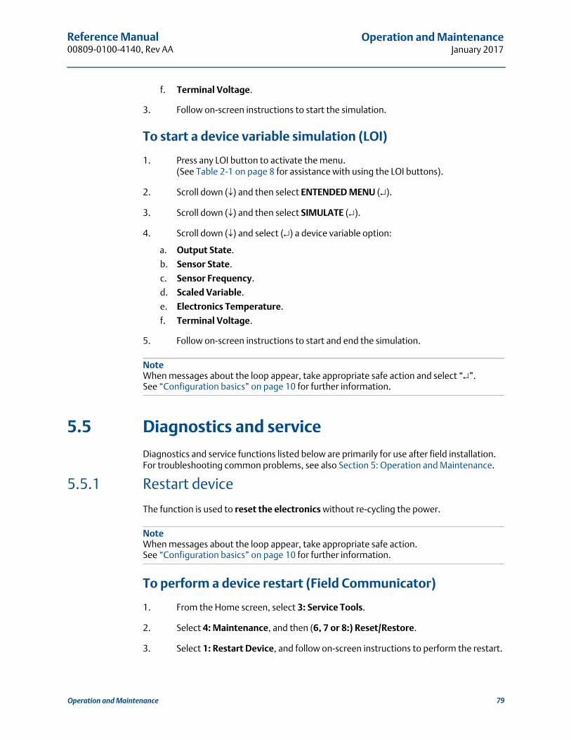
Reference Manual 00809-0100-4140, Rev AA
Operation and MaintenanceJanuary 2017
f. Terminal Voltage.
3. Follow on-screen instructions to start the simulation.
To start a device variable simulation (LOI)
1. Press any LOI button to activate the menu.(See Table 2-1 on page 8 for assistance with using the LOI buttons).
2. Scroll down () and then select ENTENDED MENU ().
3. Scroll down () and then select SIMULATE ().
4. Scroll down () and select () a device variable option:
a. Output State.
b. Sensor State.
c. Sensor Frequency.
d. Scaled Variable.
e. Electronics Temperature.
f. Terminal Voltage.
5. Follow on-screen instructions to start and end the simulation.
NoteWhen messages about the loop appear, take appropriate safe action and select “”. See “Configuration basics” on page 10 for further information.
5.5 Diagnostics and service
Diagnostics and service functions listed below are primarily for use after field installation. For troubleshooting common problems, see also Section 5: Operation and Maintenance.
5.5.1 Restart device
The function is used to reset the electronics without re-cycling the power.
NoteWhen messages about the loop appear, take appropriate safe action.See “Configuration basics” on page 10 for further information.
To perform a device restart (Field Communicator)
1. From the Home screen, select 3: Service Tools.
2. Select 4: Maintenance, and then (6, 7 or 8:) Reset/Restore.
3. Select 1: Restart Device, and follow on-screen instructions to perform the restart.
79Operation and Maintenance
Reference Manual00809-0100-4140, Rev AA
Operation and MaintenanceJanuary 2017
To perform a device restart (AMS Device Manager)
1. Right click on the device and select Service Tools.
2. Select Maintenance, and then click on the Reset/Restore tab.
3. Click on Restart Device, and follow on-screen instructions to perform the restart.
To perform a device restart (LOI)
This function is not available on the Local Operator Interface.
5.5.2 Load user defaults
The function resets variables to their ex-factory settings (see Table on page 80).
NoteWhen messages about the loop appear, take appropriate safe action.See “Configuration basics” on page 10 for further information.
To load user defaults (using Field Communicator)
1. From the Home screen, select 3: Service Tools.
2. Select 4: Maintenance, and then (6, 7, or 8:) Reset/Restore.
3. Select 2: Load User Defaults.
4. Follow on-screen instructions to load user defaults.
To load user defaults (AMS Device Manager)
1. Right click on the device and select Service Tools.
2. Select Maintenance, and then click on the Reset/Restore tab.
3. Click on Load User Defaults.
4. Follow on-screen instructions to load user defaults.
To load user defaults (LOI)
This function is not available on the Local Operator Interface.
5.5.3 Sensor frequency
The vibrating fork frequency is indicated in the Sensor Frequency device variable after sensor compensation has been applied.
Fast Keys 3, 4, 1, 1, 1
80 Operation and Maintenance
Reference Manual 00809-0100-4140, Rev AA
Operation and MaintenanceJanuary 2017
Sensor Frequency is mapped to the HART dynamic variable SV (Secondary Variable). It is indicated on the LOI (see “Local Operator Interface (LOI) display” on page 29).
To view the fork frequency (Field Communicator)
1. From the Home screen, select 3: Service Tools.
2. Select 4: Maintenance > 1: Diagnostics > 1: Sensor.
3. Select 1: Sensor Frequency.
NoteFast Key sequence 3, 2, 3, 3 also indicates the compensated fork frequency.The uncompensated fork frequency, i.e. before sensor compensation is applied,is available at fast key sequence 3, 4, 1, 1, 3.
To view the fork frequency (AMS Device Manager)
1. Right click on the device and select Service Tools.
2. Select Maintenance, and then select the Diagnostics tab.
3. Sensor Frequency is displayed in the Sensor box.
To view the fork frequency (LOI)
See “Local Operator Interface (LOI) display” on page 29.
5.5.4 Sensor compensation
The frequency of the vibrating fork sensor may be affected by a process temperature being different to the calibrated temperature. Entering a known process temperature can compensate accordingly and provide an improved frequency switching point (page 85).
To change the compensation (Field Communicator)
1. From the Home screen, select 3: Service Tools.
2. Select 4: Maintenance > 3: Calibrate Sensor > 3: Sensor Compensation.
3. Select 3: Process Temperature.
4. Enter the known process temperature.
Fast Keys 3, 4, 3, 3, 3
81Operation and Maintenance

Reference Manual00809-0100-4140, Rev AA
Operation and MaintenanceJanuary 2017
To change the compensation (AMS Device Manager)
1. Right click on the device and select Service Tools.
2. Select Maintenance, and then select the Calibrate Sensor tab.
3. Process Temperature is displayed in the Sensor Calibration box.
4. Enter the known process temperature, and select Send.
To change the compensation (LOI)
This function is not available on the Local Operator Interface.
5.5.5 Sensor state
Sensor State indicates the present state of the vibrating fork sensor.
As the vibrating fork sensor becomes immersed in a process liquid, the vibration frequency decreases and the sensor state changes to a ‘wet state’ at a switching point.
When a process liquid falls away from the fork, the vibration frequency increases and the sensor state changes to a ‘dry state’ at a switching point.
If the fork sensor becomes damaged or develops a fault, the vibrating frequency moves outside normal operating limits and the sensor state changes to ‘too dry’, ‘too wet’, or ‘zero’. (See “Dry fork frequency and switching points” on page 85 for band limits).
To view the sensor state (Field Communicator)
1. From the Home screen, select 3: Service Tools.
2. Select 4: Maintenance > 1: Diagnostics > 1: Sensor.
3. Select 4: Sensor State.
To view the sensor state (AMS Device Manager)
1. Right click on the device and select Overview.
2. Sensor State is indicated in the Primary Process Variables box.
To view the sensor state (LOI)
See “Local Operator Interface (LOI) display” on page 29 for how to configure the LOI to display this device variable.
Fast Keys 3, 4, 1, 1, 4
82 Operation and Maintenance

Reference Manual 00809-0100-4140, Rev AA
Operation and MaintenanceJanuary 2017
5.5.6 Sensor status
Sensor Status indicates if the point level device is operating in a valid or fault state.
The sensor status is dependent on the Sensor State diagnostic (page 82) and theSensor Operation Mode configuration (page 14).
NoteIf the operation mode is set to “Normal”, Sensor State cannot indicate “Too Dry”,“Too Wet”, or “Zero”, and the Sensor Status always indicates a valid state.
To view the sensor status (Field Communicator)
1. From the Home screen, select 3: Service Tools.
2. Select 4: Maintenance > 1: Diagnostics > 1: Sensor.
3. Select 5: Sensor Status.
To view the sensor status (AMS Device Manager)
1. Right click on the device and select Overview.
2. Sensor Status is indicated in the Status box.
Fast Keys 3, 4, 1, 1, 5
83Operation and Maintenance

Reference Manual00809-0100-4140, Rev AA
Operation and MaintenanceJanuary 2017
Table 5-1. Sensor Status Logic (Normal Mode)
Table 5-2. Sensor Status Logic (Enhanced Mode, Fault = Wet)
Table 5-3. Sensor Status Logic (Enhanced Mode, Fault = Dry)
Sensor Status Sensor State(1)
1. Sensor Fault Delay (page 22) does not delay the update of Sensor State when the operation mode is normal.
Current Output Operating Mode PV (Output State)
Valid Dry Wet on Off (0.0)
Valid Dry Dry on On (1.0)
Valid Wet Wet on On (1.0)
Valid Wet Dry on Off (0.0)
Sensor Status Sensor State(1)
1. Sensor Fault Delay (page 22) delays the update of Sensor State when the operation mode is enhanced.
Current Output Operating Mode PV (Output State)
Valid Dry Wet on Off (0.0)(2)
2. PV is not changed.
Valid Dry Dry on On (1.0)(2)
Fault Too Dry Wet on On (1.0)(3)
3. PV is automatically changed to on (1.0).
Valid Wet Wet on On (1.0)(2)
Valid Wet Dry on Off (0.0)(2)
Fault Too Wet Dry on On (1.0)(3)
Fault Zero Wet on On (1.0)(3)
Sensor Status Sensor State(1)
1. Sensor Fault Delay (page 22) delays the update of Sensor State when the operation mode is enhanced.
Current Output Operating Mode PV (Output State)
Valid Dry Wet on Off (0.0)(2)
2. PV is not changed.
Valid Dry Dry on On (1.0)(2)
Fault Too Dry Wet on Off (0.0)(3)
3. PV is automatically changed to off (0.0).
Valid Wet Wet on On (1.0)(2)
Valid Wet Dry on Off (0.0)(2)
Fault Too Wet Wet on Off (0.0)(3)
Fault Zero Wet on Off (0.0)(3)
84 Operation and Maintenance

Reference Manual 00809-0100-4140, Rev AA
Operation and MaintenanceJanuary 2017
5.5.7 Dry fork frequency and switching points
The Dry Fork Frequency and switching points for Sensor Status transitions, can be viewed as values on a Field Communicator or graphically on the AMS Device Manager.
Dry Fork Frequency (DFF)
This is the fork frequency recorded when the point level device is calibrated indry conditions i.e. air. The frequency is typically 1260 to 1500 Hz.
The default dry fork frequency is established at the point of manufacture. However, it can be re-established by using the dry fork calibration procedure (page 87) when the level detector is installed in a working environment.
The dry fork frequency is also used by the Media Density (page 17) and Media Learn functions (page 19).
Dry to Too Dry
Upper boundary for frequencies considered to be outside of the normal dry range.The “too dry” fault is indicated for the enhanced operating mode only.
Dry to Indeterminate
Lower boundary for frequencies considered to be outside of the normal dry range.
Wet to Indeterminate
Upper boundary for frequencies considered to be outside of the normal wet range.
Wet to Too Wet
Lower boundary for frequencies considered to be outside of the normal wet range.The “too wet” fault is indicated for the enhanced operating mode only.
Zero
The cut-off boundary, below which the sensor frequency is considered to be 0 Hz.The “zero” fault is indicated for the enhanced operating mode only.
NoteIn normal mode, a 0 Hz sensor frequency represents a wet condition (not a fault). When operating in enhanced mode, a 0 Hz sensor frequency represents a fault condition.
To view the switch points (Field Communicator)
1. From the Home screen, select 3: Service Tools.
2. Select 4: Maintenance > 1: Diagnostics > 3: Switch Points.
3. Select items 1: to 5: to see individual switching points.
To view the switch points (AMS Device Manager)
1. Right click on the device and select Overview.
2. Sensor Frequency is the default mapped dynamic variable TV in the Tertiary box.
3. The colored bands on the gauge are based on the switching points.
Fast Keys 3, 4, 1, 3
85Operation and Maintenance
Reference Manual00809-0100-4140, Rev AA
Operation and MaintenanceJanuary 2017
To view the switch points (LOI)
These device variables are not available to view on the Local Operator Interface.
5.5.8 Counters and timers
The following counters are available:
Sensor Wet Count
The count increments each time the Sensor State changes from dry to wet. This counter can be reset by entering a new value using Reset/Preset Wet Count.
Calibration Count
The Rosemount 2140 and Rosemount 2140:SIS are calibrated under reference conditions at the factory. In special circumstances, it may be re-calibrated in the field and this increments the count.
Fault Count
The count increments each time there is a fault (see “Sensor status” on page 83). This counter can be reset to zero using Reset Fault Count.
The following timers are available when in HART 7 mode:
Time Since Output Change
The time elapsed since the Output State last changed.
Total Time Dry
A totalized time for how long the Sensor State has been indicating ‘dry’.This timer can be reset to zero.
Total Time Wet
A totalized time for how long the Sensor State has been indicating ‘wet’.This timer can be reset to zero.
NoteUnits for the times are days, hours, minutes, and seconds.Seconds are not shown for long times.
To view the counters/timers menu (Field Communicator)
1. From the Home screen, select 3: Service Tools.
2. For HART 5:
a. Select 4: Maintenance > 2: Times
b. Select 1: Counters.
3. For HART 7:
a. Select 4: Maintenance > 2: Counts/Times
b. Select 1: Counters or 2: Timers.
Fast Keys 3, 4, 2, 1 or 2
86 Operation and Maintenance

Reference Manual 00809-0100-4140, Rev AA
Operation and MaintenanceJanuary 2017
4. Select individual items to see the counters and timers.
To view the counters/timers menu (AMS Device Manager)
1. Right click on the device and select Service Tools.
2. Select Maintenance, and then select the Counts/Times tab.
To view the counters or timers menu (LOI)
These device variables are not available to view on the Local Operator Interface.
5.6 Dry fork calibration
5.6.1 Site calibration of dry fork sensor
This command starts the on-site calibration of the fork sensor in dry process conditions.It should only be performed by authorized persons.
A comparison is made between the live fork sensor frequency measured in dry process conditions and original factory-set Dry Fork Frequency value (page 85).
If the difference is greater than Allowable Change In Dry Fork Frequency (page 21), the re-calibration is rejected. Check the fork for damage, corrosion, or coating, and clean the fork if necessary before re-trying.
When the calibration is successful, Dry Fork Frequency is set to the new dry frequency.See also “Dry fork frequency and switching points” on page 85 for related information.
NoteThe Dry Fork Frequency variable is available at various locations in the menu system.For convenience when calibrating, it is provided on the Field Communicator within the Sensor Calibration menu, along with the live fork sensor frequency.
To start the on-site calibration (Field Communicator)
1. From the Home screen, select 3: Service Tools.
2. Select 4: Maintenance > 3: Calibrate Sensor > 1: Sensor Calibration.
3. Select 3: Calibrate Dry Fork.
4. Follow on-screen instructions to perform the calibration.
NoteWhen messages about the loop appear, take appropriate safe action and select “OK”.See “Configuration basics” on page 10 for further information.
Fast Keys 3, 4, 3, 1, 3
87Operation and Maintenance

Reference Manual00809-0100-4140, Rev AA
Operation and MaintenanceJanuary 2017
To start the on-site calibration (AMS Device Manager)
1. Right click on the device and select Service Tools.
2. Select Maintenance, and then select the Calibrate Sensor tab.
3. Click on the Calibrate Dry Fork button in the Sensor Calibration box.
4. Follow on-screen instructions to perform the calibration.
NoteWhen messages about the loop appear, take appropriate safe action.See “Configuration basics” on page 10 for further information.
To start the on-site calibration (LOI)
1. Press any LOI button to activate the menu.(See Table 2-1 on page 8 for assistance with using the LOI buttons).
2. Scroll down () and then select EXTENDED MENU ().
3. Select CALIBRATE ().
4. Select SENSOR CAL ().
5. Follow on-screen instructions to perform the calibration.
6. Exit the menu system by either waiting one minute for the EXIT MENU? prompt, or scrolling down menus to find and select BACK TO MENU and EXIT TO MENU.
5.6.2 Restoring factory calibration of dry fork sensor
This command restores the factory calibration of the fork sensor in dry process conditions. It is accessible after a site calibration has been performed, but should only be performed by authorized persons.
To restore the factory calibration (Field Communicator)
1. From the Home screen, select 3: Service Tools.
2. Select 4: Maintenance > 3: Calibrate Sensor > 2: Reset Sensor Calibration.
3. Select 1: Restore Factory Calibration.
4. Follow on-screen instructions to restore the calibration.
NoteWhen messages about the loop appear, take appropriate safe action and select “OK”.See “Configuration basics” on page 10 for further information.
Fast Keys 3, 4, 3, 2, 1
88 Operation and Maintenance
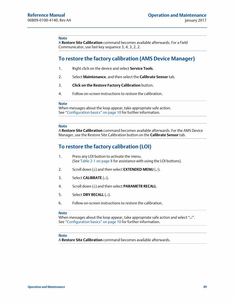
Reference Manual 00809-0100-4140, Rev AA
Operation and MaintenanceJanuary 2017
NoteA Restore Site Calibration command becomes available afterwards. For a Field Communicator, use fast key sequence 3, 4, 3, 2, 2.
To restore the factory calibration (AMS Device Manager)
1. Right click on the device and select Service Tools.
2. Select Maintenance, and then select the Calibrate Sensor tab.
3. Click on the Restore Factory Calibration button.
4. Follow on-screen instructions to restore the calibration.
NoteWhen messages about the loop appear, take appropriate safe action.See “Configuration basics” on page 10 for further information.
NoteA Restore Site Calibration command becomes available afterwards. For the AMS Device Manager, use the Restore Site Calibration button on the Calibrate Sensor tab.
To restore the factory calibration (LOI)
1. Press any LOI button to activate the menu.(See Table 2-1 on page 8 for assistance with using the LOI buttons).
2. Scroll down () and then select EXTENDED MENU ().
3. Select CALIBRATE ().
4. Scroll down () and then select PARAMETR RECALL.
5. Select DRY RECALL ().
6. Follow on-screen instructions to restore the calibration.
NoteWhen messages about the loop appear, take appropriate safe action and select “”. See “Configuration basics” on page 10 for further information.
NoteA Restore Site Calibration command becomes available afterwards.
89Operation and Maintenance

Reference Manual00809-0100-4140, Rev AA
Operation and MaintenanceJanuary 2017
5.6.3 Sensor calibration status and calibration count
Sensor Calibration Status indicates:
Factory Calibrated – No further calibration is normally required.
Site Calibrated – Calibration successfully performed on-site.
Un-calibrated – Calibration is required. Contact the factory.
The Rosemount 2140 and Rosemount 2140:SIS are supplied with an ex-factory calibration, but can optionally be calibrated on-site using the Calibrate Dry Fork command (page 87).
Calibration Count stores the number of times a site calibration has been performed.
To view sensor calibration status and calibration count(Field Communicator)
1. From the Home screen, select 3: Service Tools.
2. Select 4: Maintenance > 3: Calibrate Sensor > 1: Sensor Calibration.
3. Select 4: Sensor Calibration Status or select 5: Calibration Count.
To view sensor calibration status and calibration count(AMS Device Manager)
1. Right click on the device and select Service Tools.
2. Select Maintenance, and then select the Calibrate Sensor tab.
3. The Sensor Calibration Status and Calibration Count variables are in the Sensor Calibration box.
To view sensor calibration status and calibration count (LOI)
This data is not available on the Local Operator Interface.
5.6.4 Configuring Power Advisory Diagnostic
Introduction
The optional Power Advisory diagnostic provides a means to detect issues that may jeopardize the integrity of the electrical loop. Some examples are: water entering the wiring compartment and making contact with the terminals, an unstable power supply nearing end of life, or heavy corrosion on the terminals.
This technology is based on the premise that, after a Rosemount 2140 or 2140:SIS (“level detector”) is installed and powered up, the electrical loop has a baseline characteristic that reflects the proper installation. If the level detector terminal voltage deviates from the
Fast Keys 3, 4, 3, 1, 4 or 5
90 Operation and Maintenance

Reference Manual 00809-0100-4140, Rev AA
Operation and MaintenanceJanuary 2017
baseline and outside the user configured threshold, the level detector can generate a HART alert or analog alarm.
To make use of this diagnostic, the user must first create a baseline characteristic for the electrical loop after the level detector has been installed. The loop is automatically characterized with the push of a button. This creates a linear relationship for expected terminal voltage values along the operating region from 4 – 20 mA (see Figure 5-2).
Figure 5-2. Baseline Operating Region
A. Terminal voltage B. Output current
Overview
The Rosemount 2140 and 2140:SIS Level Detectors (“level detectors”), with Extended Features Packages, are shipped with the Power Advisory function switched off and without any loop characterization performed. After the level detector is installed and powered-up, the loop characterization must be performed for Power Advisory to function.
When the user initiates a loop characterization, the level detector checks to see if the loop has sufficient power for proper operation. Next, the output is driven to 4 and 20 mA points to establish a baseline and determine the maximum allowable terminal voltage deviation. After this is complete, the user enters a sensitivity threshold called “Terminal Voltage Deviation Limit”. A check is made to make sure this threshold value is valid.
With the loop characterized and Terminal Voltage Deviation Limit is set, the Power Advisory function actively monitors the electrical loop for deviations from the baseline. Now, the level detector generates an alert or alarm whenever the terminal voltage changes (relative to the expected baseline value) and exceeds the Terminal Voltage Deviation Limit.
NotePower Advisory monitors and detects changes in the terminal voltage from expected values to detect common failures. It is not possible to predict and detect all types of electrical failures on the 4-20 mA analog output. Therefore, Emerson cannot absolutely warrant or guarantee that Power Advisory will accurately detect failures under all circumstances.
10.5
4 mA 20 mA
B
A
42.5
91Operation and Maintenance

Reference Manual00809-0100-4140, Rev AA
Operation and MaintenanceJanuary 2017
Terminal voltage
This field shows the current terminal voltage value in volts. The terminal voltage is a dynamic value and is directly related to the mA output value.
Terminal voltage deviation limit +/-
The Terminal Voltage Deviation Limit should be set large enough such that expected voltage changes do not cause false failures.
Figure 5-3. Voltage Deviation Limit
Resistance
This value is the calculated resistance of the electrical loop (in ) measured during the loop characterization procedure. Changes in the resistance may occur due to changes in the physical condition of the loop installation. Baseline and previous baselines can be compared to see how much resistance has changed over time.
Power supply
This value is the calculated power supply voltage of the electrical loop (in volts) measured during the loop characterization procedure. Changes in this value may occur due to degraded performance of the power supply. Baseline and previous baselines can be compared to see how much the power supply has changed over time.
Severe changes in the electrical loop may inhibit HART communication or the ability to reach alarm values. Therefore, Emerson cannot absolutely warrant or guarantee that the correct failure alarm level (high or low) can be read by the host system at the time of annunciation.
92 Operation and Maintenance

Reference Manual 00809-0100-4140, Rev AA
Operation and MaintenanceJanuary 2017
Characterize loop
Loop characterization must be initiated when the level detector is first installed or when electrical loop characteristics have been intentionally altered. Examples include a modified power supply level or loop resistance of the system, changing the terminal block on the level detector, or adding a Smart Wireless THUM to the level detector.
NotePower Advisory is not recommended for a level detector operating in multi-drop mode.
Power Advisory action
When the voltage deviation exceeds the set limit, four possible actions can be configured and can be set to “Latched” or “Unlatched”.
When the alert or alarm is unlatched, the alert or alarm will disappear if voltage deviation returns to a normal level. A latched alarm or alert will not disappear when the voltage deviation returns to normal levels. This requires the user to acknowledge and clear the alert or alarm.
The four Power Advisory diagnostic actions are:
None
Alert latched
Alarm unlatched
Alert unlatched
NoteWhen messages about the loop appear, take appropriate safe action.See “Configuration basics” on page 10 for further information.
Configuring Power Advisory (Field Communicator)
1. From the Home screen, select 2: Configure.
2. Select 1: Guided Setup.
3. Select (5: or 6:) Power Advisory.
4. Follow on-screen instructions to configure the Power Advisory function.
Configuring Power Advisory (AMS Device Manager)
1. Right click on the device and select Configure.
2. Select Guided Setup.
3. Click the Power Advisory button.
4. Follow on-screen instructions to configure the Power Advisory function.
Fast Keys 2, 1, 5 or 6
93Operation and Maintenance

Reference Manual00809-0100-4140, Rev AA
Operation and MaintenanceJanuary 2017
Configuring Power Advisory (LOI)
This function is not available on the Local Operator Interface.
5.7 Frequency profiling functions
There are two frequency profiling functions supported on a level detector with the Extended Features Package (EFP) enabled:
Minimum deviation
Maximum deviation
Both functions monitor the sensor frequency change for a defined time duration. An alert is generated whenever the maximum frequency variation is smaller or larger than the pre-set thresholds (minimum deviation duration or maximum deviation duration as applicable).
Figure 5-4. Frequency Profile Definition
Minimum Deviation - The smallest change in Sensor Frequency that must occur during the Minimum Deviation
Duration in order to prevent an alert from being generated.
Minimum Deviation Duration - the period of time in which the Sensor Frequency must change by more than the
Minimum Deviation in order to prevent an alert from being generated.
Maximum Deviation - The change in Sensor Frequency occurring during the Maximum Deviation Duration that will
cause an alert to be generated.
Maximum Deviation Duration - the period of time during which a change in the Sensor Frequency greater than the
Maximum Deviation will cause an alert to be generated.
Fast Keys 2, 2, 8
94 Operation and Maintenance
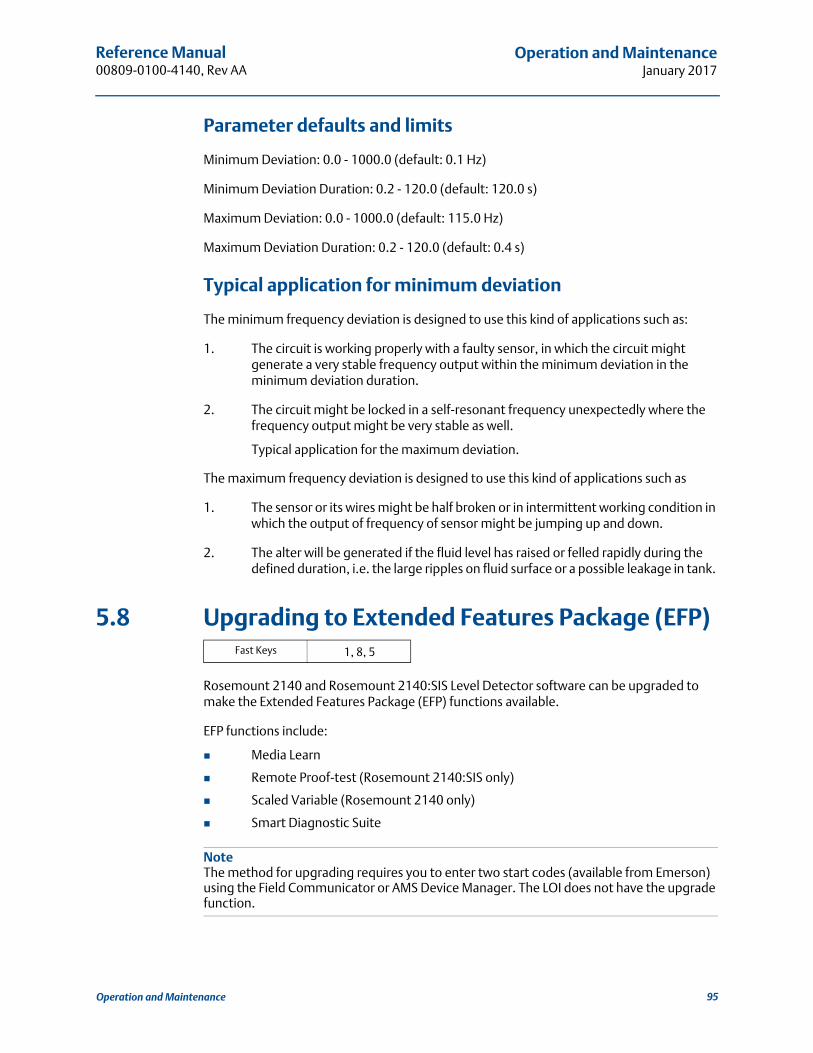
Reference Manual 00809-0100-4140, Rev AA
Operation and MaintenanceJanuary 2017
Parameter defaults and limits
Minimum Deviation: 0.0 - 1000.0 (default: 0.1 Hz)
Minimum Deviation Duration: 0.2 - 120.0 (default: 120.0 s)
Maximum Deviation: 0.0 - 1000.0 (default: 115.0 Hz)
Maximum Deviation Duration: 0.2 - 120.0 (default: 0.4 s)
Typical application for minimum deviation
The minimum frequency deviation is designed to use this kind of applications such as:
1. The circuit is working properly with a faulty sensor, in which the circuit might generate a very stable frequency output within the minimum deviation in the minimum deviation duration.
2. The circuit might be locked in a self-resonant frequency unexpectedly where the frequency output might be very stable as well.
Typical application for the maximum deviation.
The maximum frequency deviation is designed to use this kind of applications such as
1. The sensor or its wires might be half broken or in intermittent working condition in which the output of frequency of sensor might be jumping up and down.
2. The alter will be generated if the fluid level has raised or felled rapidly during the defined duration, i.e. the large ripples on fluid surface or a possible leakage in tank.
5.8 Upgrading to Extended Features Package (EFP)
Rosemount 2140 and Rosemount 2140:SIS Level Detector software can be upgraded to make the Extended Features Package (EFP) functions available.
EFP functions include:
Media Learn
Remote Proof-test (Rosemount 2140:SIS only)
Scaled Variable (Rosemount 2140 only)
Smart Diagnostic Suite
NoteThe method for upgrading requires you to enter two start codes (available from Emerson) using the Field Communicator or AMS Device Manager. The LOI does not have the upgrade function.
Fast Keys 1, 8, 5
95Operation and Maintenance

Reference Manual00809-0100-4140, Rev AA
Operation and MaintenanceJanuary 2017
To upgrade to Extended Features Package(Field Communicator)
1. From the Home screen, select 1: Overview.
2. Select 8: Device Information > 5: Device Upgrade
3. If proceeding with upgrade:
a. Select 5: Upgrade.
b. Follow on-screen instructions to enter the two start codes.
4. If checking the upgrade success or current model:
a. Select 1: Model or select 2: Upgrade Options.
To upgrade to Extended Features Package(AMS Device Manager)
1. Right click on the device and select Overview.
2. Click on the Device Information button.
3. Click on the Upgrade Device tab.
4. If a tick is indicated against a ready to upgrade option:
a. Click on the Upgrade button.
b. Follow on-screen instructions to enter the two start codes.
5. Verify the upgrade success by viewing the Upgrade Device tab again.
96 Operation and Maintenance

Reference Manual 00809-0100-4140, Rev AA
TroubleshootingJanuary 2017
Section 6 Troubleshooting
6.1 Overview
Table 6-1 provides summarized maintenance and troubleshooting suggestions for the most common operating problems. If you suspect malfunction despite the absence of any diagnostic messages on the Field Communicator display, consider using Section 5: Operation and Maintenance to identify any potential problem.
6.2 Safety messages
Procedures and instructions in this section may require special precautions to ensure the safety of the personnel performing the operations. Information that raises potential safety issues is indicated by a warning symbol ( ). Refer to the following safety messages before performing an operation preceded by this symbol.
Explosions could result in death or serious injury.
Installation of this Rosemount 2140 and 2140:SIS Level Detector (“level detector”) in an explosive environment must be in accordance with the appropriate local, national, and international standards, codes, and practices.
Please review Appendix B: Product Certifications for any restrictions associated with a safe installation.
Before connecting a Field Communicator in an explosive atmosphere, ensure the instruments in the loop are installed in accordance with intrinsically safe or non-incendive field wiring practices.
In an explosion-proof/flameproof installation, do not remove the level detector covers when power is applied to the unit.
Process leaks may cause harm or result in death.
Install and tighten process connectors before applying pressure.
Electrical shock can result in death or serious injury.
Avoid contact with the leads and terminals. High voltage that may be present on leads can cause electrical shock.
External surface may be hot.
Care must be taken to avoid possible burns. The flange and process seal may be hot at high process temperatures. Allow time to cool before servicing.
97Troubleshooting

Reference Manual00809-0100-4140, Rev AA
TroubleshootingJanuary 2017
6.3 Troubleshooting for 4-20 mA Output
Table 6-1. Rosemount 2140 Troubleshooting for 4-20 mA Output
6.4 Diagnostic messages
Listed in the below sections are detailed table of the possible messages that will appear on either the LCD/LOI Display, a Field Communicator, or an AMS system. Use the tables below to diagnose particular status messages.
Good
Failed – fix now
Maintenance – fix soon
Advisory
Listed in the below sections are detailed tables of the possible messages that will appear on either: LOI display, Field Communicator, or an AMS system.
Symptom Corrective actions
Level detector milliamp readingis zero
Verify terminal voltage is 10.5 to 42.4 Vdc at signal terminals
Check power wires for reversed polarity
Check that power wires are connected to signal terminals
Check for open diode across test terminal
Level detector not communicating with Field Communicator
Verify terminal voltage is 10.5 to 42.4 Vdc
Check loop resistance, 250 minimum (PS voltage -level detector voltage/loop current)
Check that power wires are connected to signal terminals and not test terminals
Verify clean DC Power to level detector (Max AC noise 0.2 volts peak to peak)
Verify the output is between 4 and 20 mA or saturation levels
Have Field Communicator poll for all addresses
Level detector milliamp reading islow or high
Verify 4 and 20 mA range points
Verify output is not in alarm condition
Perform analog trim
Check that power wires are connected to the correct signal terminals (positive to positive, negative to negative) and not the test terminal
Milliamp reading is erratic Verify power source to level detector has adequate voltage and current
Check for external electrical interference
Verify level detector is properly grounded
Verify shield for twisted pair is only grounded at one end
98 Troubleshooting

Reference Manual 00809-0100-4140, Rev AA
TroubleshootingJanuary 2017
6.4.1 Diagnostic message: failed - fix now
Table 6-2. Status: Failed – Fix Now
6.4.2 Diagnostic message: maintenance - fix soon
Table 6-3. Status: Maintenance – Fix Soon
Alert name LOI screen Problem Recommended action
Electronics Board Failure
FAILBOARD
A failure has been detected in the electronics circuit board
1.Contact your local Emerson representative for advice.
Critical Electronics Data Error
MEMORYERROR
A user written parameter does not match the expected value
1.Confirm and correct all parameters listed in Device Information.
2.Perform a Device Reset.
3.Replace electronics board.
Sensor Failure
FAILSENSOR
A failure has been detected in the fork sensor
1.Contact Customer Services.
Alert name LOI screen Problem Recommended action
Electronics Temperature Beyond Limits
TEMP OUTLIMITS
The temperature of the electronics has exceeded its safe operating range.
1.Confirm electronics temperature is within limits of –40 to 175 °F (–40 to 80 °C) with or without the LOI display.
2.Contact your local Emerson representative for advice.
Power Advisory Diagnostic
POWERADVISE
The level detector has detected a deviation of the terminal voltage outside of configured limits. This may indicate degraded electrical or loop integrity
1.Check the dc power supply to ensure power is correct, stable, and has minimal ripple.
2.Check loop wiring for degradation or improper grounding.
3.Remove the wiring compartment cover (considering hazardous location requirements) to check for presence or water or corrosion.
If conditions have resumed to normal, clicking on Reset Alert will clear the alert.
Electronics Board Parameter Error
MEMORYWARN
(also inadvisory)
A device parameter does not match the expected value. The error does not affect level detector operation or analog output.
1.Contact your local Emerson representative for advice.
Configuration Buttons Operator Error
STUCKBUTTON
Device is not responding to button presses.
1.Check configuration buttons are not stuck.
2.Contact your local Emerson representative for advice.
99Troubleshooting
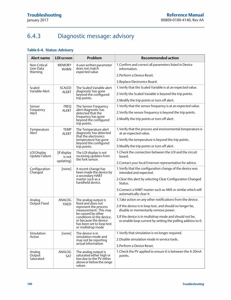
Reference Manual00809-0100-4140, Rev AA
TroubleshootingJanuary 2017
6.4.3 Diagnostic message: advisory
Table 6-4. Status: Advisory
Alert name LOI screen Problem Recommended action
Non-Critical User Data Warning
MEMORYWARN
A user written parameter does not match expected value
1.Confirm and correct all parameters listed in Device Information.
2.Perform a Device Reset.
3.Replace Electronics Board.
Scaled Variable Alert
SCALEDALERT
The Scaled Variable alert diagnostic has gone beyond the configured trip points.
1.Verify that the Scaled Variable is at an expected value.
2.Verify the Scaled Variable is beyond the trip points.
3.Modify the trip points or turn off alert.
Sensor Frequency Alert
FREQALERT
The Sensor Frequency alert diagnostic has detected that the frequency has gone beyond the configured trip points.
1.Verify that the sensor frequency is at an expected value.
2.Verify the sensor frequency is beyond the trip points.
3.Modify the trip points or turn off alert.
Temperature Alert
TEMPALERT
The Temperature alert diagnostic has detected that the electronics temperature has gone beyond the configured trip points.
1.Verify that the process and environmental temperature is at an expected value.
2.Verify the temperature is beyond the trip points.
3.Modify the trip points or turn off alert.
LOI Display Update Failure
[If displayis not
updating]
The LOI display is not receiving updates from the fork sensor.
1.Check the connection between the LOI and the circuit board.
2.Contact your local Emerson representative for advice.
Configuration Changed
[none] A recent change has been made the device by a secondary HART master such as a handheld device.
1.Verify that the configuration change of the device was intended and expected.
2.Clear this alert by selecting Clear Configuration Changed Status.
3.Connect a HART master such as AMS or similar which will automatically clear it.
Analog Output Fixed
ANALOGFIXED
The analog output is fixed and does not represent the process measurement. This may be caused by other conditions in the device, or because the device has been set to loop test or multidrop mode
1.Take action on any other notifications from the device.
2.If the device is in loop test, and should no longer be, disable or momentarily remove power.
3.If the device is in multidrop mode and should not be, re-enable loop current by setting the polling address to 0.
Simulation Active
[none] The device is in simulation mode and may not be reporting actual information
1.Verify that simulation is no longer required.
2.Disable simulation mode in service tools.
3.Perform a Device Reset.
Analog Output Saturated
ANALOGSAT
The analog output is saturated either high or low due to the PV either above or below the range values
1.Check the PV applied to ensure it is between the 4-20mA points.
100 Troubleshooting

Reference Manual 00809-0100-4140, Rev AA
TroubleshootingJanuary 2017
6.5 Service support
Within the United States, call the Emerson Response Center using the 1-800-654-RSMT (7768) toll-free number. This center, available 24 hours a day, will assist you with any needed information or materials.
The center will ask for product model and serial numbers, and will provide a Return Material Authorization (RMA) number. The center will also ask for the process material to which the product was last exposed.
For inquiries outside of the United States, contact the nearest Emerson representative for RMA instructions. To expedite the return process outside of the United States, contact the nearest Emerson representative.
Emerson Response Center representatives will explain the additional information and procedures necessary to return goods exposed to hazardous substances.
Individuals who handle products exposed to a hazardous substance can avoid injury if they are informed of and understand the hazard. The product being returned will require a copy of the required Material Safety Data Sheet (MSDS) for each substance to be included with the returned goods.
101Troubleshooting

Reference Manual00809-0100-4140, Rev AA
TroubleshootingJanuary 2017
102 Troubleshooting

Specifications and Reference DataJanuary 2017
Reference Manual00809-0100-4140, Rev AA
Appendix A Specifications and Reference Data
Specifications . . . . . . . . . . . . . . . . . . . . . . . . . . . . . . . . . . . . . . . . . . . . . . . . . . . . . . . . . . . . . . . . . . . . page 103Dimensional drawings . . . . . . . . . . . . . . . . . . . . . . . . . . . . . . . . . . . . . . . . . . . . . . . . . . . . . . . . . . . . . page 106Ordering information . . . . . . . . . . . . . . . . . . . . . . . . . . . . . . . . . . . . . . . . . . . . . . . . . . . . . . . . . . . . . page 115
A.1 Specifications
A.1.1 General
Products
Rosemount 2140 and Rosemount 2140:SIS Level Detectors.
Measuring technology
Vibrating fork.
Applications
Most liquids including coating liquids, aerated liquids, and slurries.
A.1.2 Physical specifications
Material selection
Emerson provides a variety of Rosemount product with various product options and configurations including materials of construction that can be expected to perform well in a wide range of applications. The Rosemount product information presented is intended as a guide for the purchaser to make an appropriate selection for the application. It is the purchaser’s sole responsibility to make a careful analysis of all process parameters (such as all chemical components, temperature, pressure, flow rate, abrasives, contaminants, etc.), when specifying product, materials, options and components for the particular application.
Emerson is not in a position to evaluate or guarantee the compatibility of the process fluid or other process parameters with the product, options, configuration or materials of construction selected.
Electronics housing
Materials
Aluminum Alloy ASTM B85 A360.0 orStainless steel (316C)
Rotation
Rotatable housing to allow more convenient cable position.
Display
Optional two-line LCD display with Local Operator Interface (LOI) by selecting option code M4. There are two internal and two external configuration buttons. Includes extended cover with glass window.
Device-test button
The Rosemount 2140 can have an single external button for device testing by selecting the DP option code. (This is not selectable if the LCD with LOI option is selected).
Proof-test button
The Rosemount 2140:SIS comes supplied with an external button for local proof-testing. This can be upgraded to the LCD with LOI by selecting the M4 option code.
Conduit entries
Two M20 X 1.5 or ½-in ANPT conduit entries for cabling.
Rosemount 2140 ships with dust caps installed in the conduit entries. One blanking plug is supplied in a plastic bag, ready to be installed. No cables or cable glands are supplied.
Ingress protection
IP66/67 to EN60529, NEMA® 4X (when supplied blanking plug and suitably-rated cable glands are used).
Process wetted connections
Threaded, Tri Clamp, and flanged process connections.See Table A-6 on page 115 for a full list.
Materials
316/316L Stainless Steel (1.4401/1.4404 dual certified). Mechanically polished option to better than 0.1 m for Tri Clamp connections.
Alloy C (UNS N10002) and Alloy C-276 (UNS N10276) – available for flanged and selected threaded process connections (3/4- and 1-in. BSPT (R), and 3/4- and 1-in. NPT).
ECTFE co-polymer coated 316/316L Stainless Steel (1.4401/1.4404 dual certified) – only available for a flanged Rosemount 2140 but excludes 1-in./DN25/25A flanges.
103Specifications and Reference Data

Specifications and Reference DataJanuary 2017
Reference Manual 00809-0100-4140, Rev AA
Gasket material for 3/4- and 1-in. BSPP (G) process connection is non-asbestos BS7531 Grade X carbon fiber with rubber binder. Gaskets are not supplied with flanged process connections.
Extended fork lengths
The maximum extended length is 157.5 in. (4000 mm) except for ECTFE copolymer coating and polished process connection options which have a maximum length of 59.1 in. (1500 mm) and 39.4 in. (1000 mm) respectively.
Table A-1 has a summary of the minimum extended lengths.See “Dimensional drawings” on page 106 for other dimensions.
Table A-1. Minimum Extended Lengths
A.1.3 Performance specifications
Hysteresis (water)
Approximately 0.1 in. (2.5 mm).
Switching point (water)
Approximately 0.5 in. (13 mm) from tip of fork (if vertical installation) or from edge of fork (if horizontal installation).
Switching points vary with different liquid densities. The Rosemount 2140, with Extended Features Package added, allows pre-selection of a liquid type, and has a built-in learning function to make it even easier.
Switching delay
Switching delay is programmable from 0 to 3600 seconds. Default delay is 1 second.
Liquid density ranges
Low (400 to 600 kg/m3), medium (500 to 900 kg/m3), standard (800 to 1300 kg/m3), and high (1200 to 3000 kg/m3)
Liquid viscosity ranges
Up to 1000 cP (centiPoise) in Enhanced mode.
Up to 10000 cP (centiPoise) in Normal mode.
A.1.4 Electrical specifications
Power supply
10.5 to 42.4 Vdc (with no load).
Output
Software selectable analog output type:– 8/16 mA HART switched output state,– Custom mA HART switched output state,– 4–20 mA HART, or– LEVELTESTER switched output state.
Digital process variable is superimposed on 4-20 mA signal, available to any host that conforms to HART protocol.
Selectable digital HART revisions, HART5 (default) or HART7. The revision can be switched using any HART-based configuration tool or the optional local operator interface.
Grounding
The Rosemount 2140 and Rosemount 2140:SIS must always be grounded through the provided external ground connection.
Terminal connections (wire diameter)
Minimum 24 AWG and maximum 14 AWG (0.2 to 2.5 mm2)
A.1.5 Environmental specifications
Ambient temperature limits
–40 to 175 °F (–40 to 80 °C) with or without the LOI display.
See also Appendix B: Product Certifications for the reduced ambient temperature limits required by approvals.
Minimum and maximum operating temperatures
See Figure A-1 for operating temperatures.
Check Appendix B: Product Certifications for the operating temperature ranges covered by the approvals.
Maximum operating pressures
The final rating depends on the selected process connection.
Threaded connection: See Figure A-2 for operating pressures.
Tri Clamp connection: 435 psig (30 bar g).
Flanged connection: See Figure A-2 or Table A-2 (whichever gives the lowest pressure).
Process connection Minimum extended length
3/4–in. threaded 3.8 in. (95 mm)
1–in. threaded 3.7 in. (94 mm)
Flanged 3.5 in. (89 mm)
Tri Clamp 4.1 in. (105 mm)
104 Specifications and Reference Data
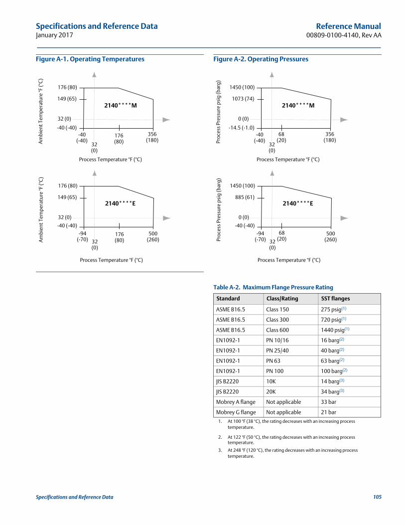
Specifications and Reference DataJanuary 2017
Reference Manual00809-0100-4140, Rev AA
Figure A-1. Operating Temperatures Figure A-2. Operating Pressures
Table A-2. Maximum Flange Pressure Rating
176 (80)
176 (80)
-40 (-40)-40
(-40)356
(180)
Process Temperature °F (°C)
Am
bien
t Tem
pera
ture
°F (°
C)
149 (65)
32 (0)
32 (0)
176 (80)
176 (80)
-40 (-40)
-94 (-70)
500 (260)
Process Temperature °F (°C)
Am
bien
t Tem
pera
ture
°F (°
C)
149 (65)
32 (0)
32 (0)
2140****M
2140****E
Standard Class/Rating SST flanges
ASME B16.5 Class 150 275 psig(1)
1. At 100 °F (38 °C), the rating decreases with an increasing process temperature.
ASME B16.5 Class 300 720 psig(1)
ASME B16.5 Class 600 1440 psig(1)
EN1092-1 PN 10/16 16 barg(2)
EN1092-1 PN 25/40 40 barg(2)
EN1092-1 PN 63 63 barg(2)
2. At 122 °F (50 °C), the rating decreases with an increasing process temperature.
EN1092-1 PN 100 100 barg(2)
JIS B2220 10K 14 barg(3)
3. At 248 °F (120 °C), the rating decreases with an increasing process temperature.
JIS B2220 20K 34 barg(3)
Mobrey A flange Not applicable 33 bar
Mobrey G flange Not applicable 21 bar
1450 (100)
68 (20)
-14.5 (-1.0)-40
(-40)356
(180)
Process Temperature °F (°C)
Proc
ess
Pres
sure
psi
g (b
arg)
1073 (74)
0 (0)
32 (0)
1450 (100)
68 (20)
-40 (-40)
-94 (-70)
500 (260)
Process Temperature °F (°C)
Proc
ess
Pres
sure
psi
g (b
arg)
885 (61)
0 (0)
32 (0)
2140****M
2140****E
105Specifications and Reference Data
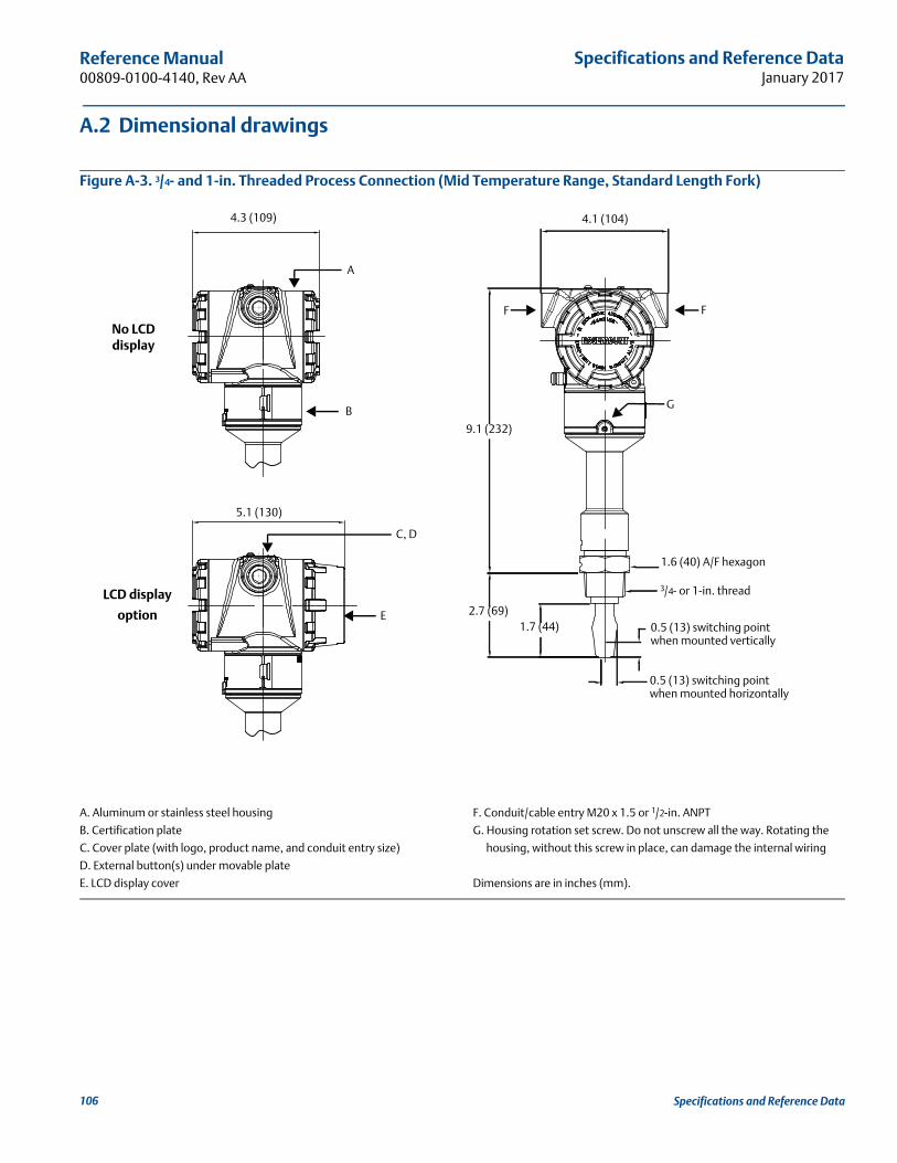
Specifications and Reference DataJanuary 2017
Reference Manual 00809-0100-4140, Rev AA
A.2 Dimensional drawings
Figure A-3. 3/4- and 1-in. Threaded Process Connection (Mid Temperature Range, Standard Length Fork)
A. Aluminum or stainless steel housing
B. Certification plate
C. Cover plate (with logo, product name, and conduit entry size)
D. External button(s) under movable plate
E. LCD display cover
F. Conduit/cable entry M20 x 1.5 or 1/2-in. ANPT
G. Housing rotation set screw. Do not unscrew all the way. Rotating the
housing, without this screw in place, can damage the internal wiring
Dimensions are in inches (mm).
4.3 (109)
5.1 (130)
4.1 (104)
LCD display
option
No LCD display
E
A
B
C, D
F
G
F
9.1 (232)
2.7 (69)1.7 (44)
0.5 (13) switching point when mounted horizontally
0.5 (13) switching point when mounted vertically
1.6 (40) A/F hexagon
3/4- or 1-in. thread
106 Specifications and Reference Data

Specifications and Reference DataJanuary 2017
Reference Manual00809-0100-4140, Rev AA
Figure A-4. 3/4- and 1-in. Threaded Process Connection (Mid Temperature Range, Extended Length Fork)
A. Aluminum or stainless steel housing
B. Certification plate
C. Cover plate (with logo, product name, and conduit entry size)
D. External button(s) under movable plate
E. LCD display cover
F. Conduit/cable entry M20 x 1.5 or 1/2-in. ANPT
G. Housing rotation set screw. Do not unscrew all the way. Rotating the
housing, without this screw in place, can damage the internal wiring
Dimensions are in inches (mm).
Table A-3. Fork Length for 3/4- and 1-in. Threaded Rosemount 2140
4.3 (109)
5.1 (130)
4.1 (104)
LCD display
option
No LCD display
E
A
B
C, D
F
G
F
9.9 (253)
E (M)customer specified
length
1.7 (44)
0.5 (13) switching point when mounted horizontally
0.5 (13) switching point when mounted vertically
1.6 (40) A/F hexagon
3/4- or 1-in. thread
Ø1.14 (29) for 1-in. threadØ0.9 (23) for 3/4-in. thread
Processconnection
Standard lengthfork length code A
Minimum lengthfork length code E (M)
Maximum length fork length code E (M)
3/4-in. thread 1.7 in. (44 mm) 3.75 in. (95 mm) 157.5 in. (4000 mm)
1-in. thread 1.7 in. (44 mm) 3.74 in. (94 mm) 157.5 in. (4000 mm)
107Specifications and Reference Data

Specifications and Reference DataJanuary 2017
Reference Manual 00809-0100-4140, Rev AA
Figure A-5. 3/4- and 1-in. Threaded Process Connection (High Temperature Range, All Fork Lengths)
A. Thermal tube
Dimensions are in inches (mm).
For dimensions and features not shown here, see Figure A-3 on page 106.
4.1 (104)4.1 (104)
17.7 (449)
E (M)customer specified
length
1.7 (44)
0.5 (13) switching point when mounted horizontally
0.5 (13) switching point when mounted vertically
1.6 (40) A/F hexagon
3/4- or 1-in. thread
Ø1.14 (29) for 1-in. threadØ0.9 (23) for 3/4-in. thread
16.9 (428)
1.7 (44)2.8 (70)
1.6 (40) A/F hexagon
3/4- or 1-in. thread
0.5 (13) switching pointwhen mounted
horizontally
0.5 (13) switching pointwhen mountedvertically
108 Specifications and Reference Data
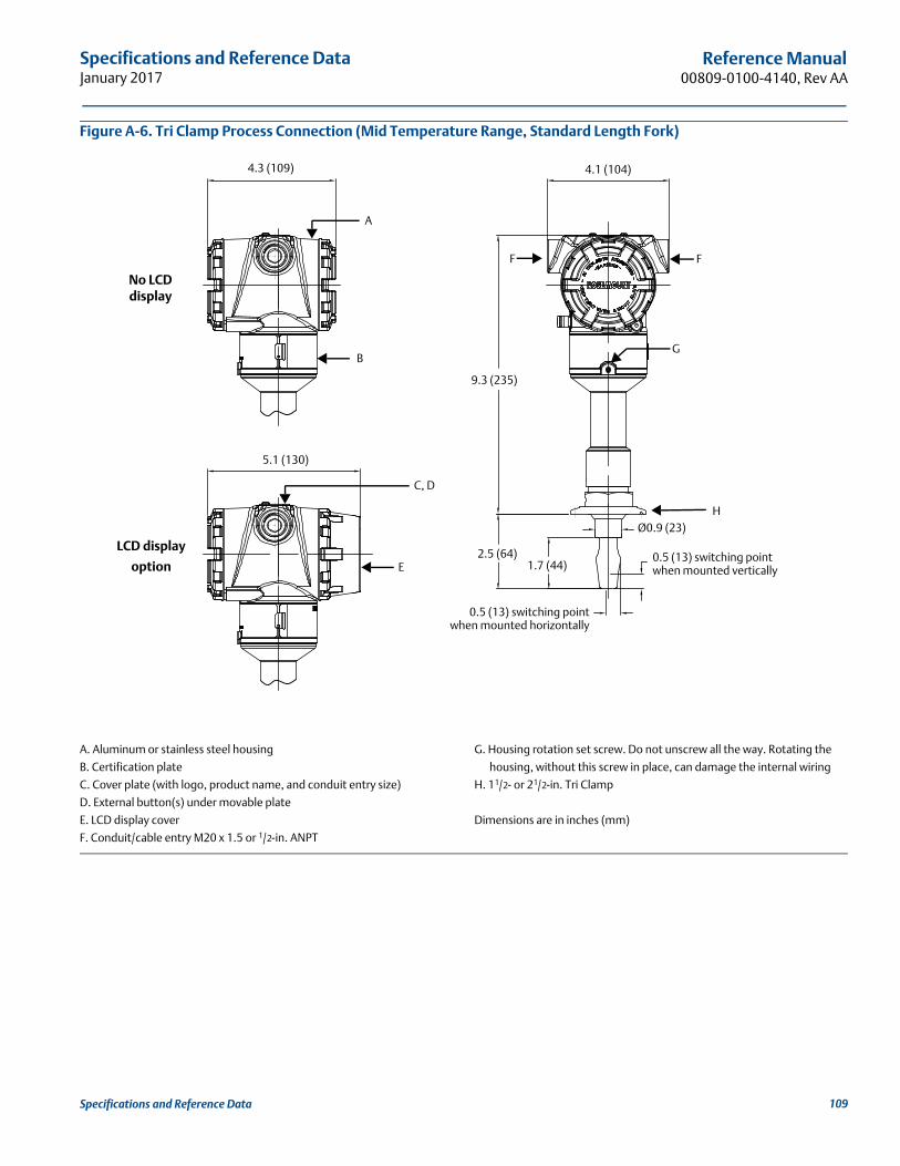
Specifications and Reference DataJanuary 2017
Reference Manual00809-0100-4140, Rev AA
Figure A-6. Tri Clamp Process Connection (Mid Temperature Range, Standard Length Fork)
A. Aluminum or stainless steel housing
B. Certification plate
C. Cover plate (with logo, product name, and conduit entry size)
D. External button(s) under movable plate
E. LCD display cover
F. Conduit/cable entry M20 x 1.5 or 1/2-in. ANPT
G. Housing rotation set screw. Do not unscrew all the way. Rotating the
housing, without this screw in place, can damage the internal wiring
H. 11/2- or 21/2-in. Tri Clamp
Dimensions are in inches (mm)
4.3 (109)
5.1 (130)
4.1 (104)
LCD display
option
No LCD display
E
A
B
C, D
F
G
F
9.3 (235)
2.5 (64)1.7 (44)
0.5 (13) switching pointwhen mounted horizontally
0.5 (13) switching point when mounted vertically
Ø0.9 (23)H
109Specifications and Reference Data

Specifications and Reference DataJanuary 2017
Reference Manual 00809-0100-4140, Rev AA
Figure A-7. Tri Clamp Process Connection (Mid Temperature Range, Extended Length Fork)
A. Aluminum or stainless steel housing
B. Certification plate
C. Cover plate (with logo, product name, and conduit entry size)
D. External button(s) under movable plate
E. LCD display cover
F. Conduit/cable entry M20 x 1.5 or 1/2-in. ANPT
G. Housing rotation set screw. Do not unscrew all the way. Rotating the
housing, without this screw in place, can damage the internal wiring
H. 11/2- or 21/2-in. Tri Clamp
Dimensions are in inches (mm).
Table A-4. Fork Length for Hygienic Rosemount 2140
4.3 (109)
5.1 (130)
4.1 (104)
LCD display
option
No LCD display
E
A
B
C, D
F
G
F
9.6 (244)
E (M)customer specified
length
1.7 (44)
0.5 (13) switching point when mounted horizontally
0.5 (13) switching point when mounted vertically
Ø1.6 (39)
Ø1.14 (29)
H
Processconnection
Standard lengthfork length code A
Minimum lengthfork length code E (M)
Maximum length fork length code E (M)
Tri Clamp 1.7 in. (44 mm) 4.13 in. (105 mm) 157.5 in. (4000 mm)
O-ring seal (1-in. BSPP)(1)
1. For these dimension drawings, refer to the Rosemount 2140 Type 1 drawings at Emerson.com/Rosemount.
1.7 in. (44 mm) 4.13 in. (105 mm) 38.4 in. (1000 mm)
110 Specifications and Reference Data
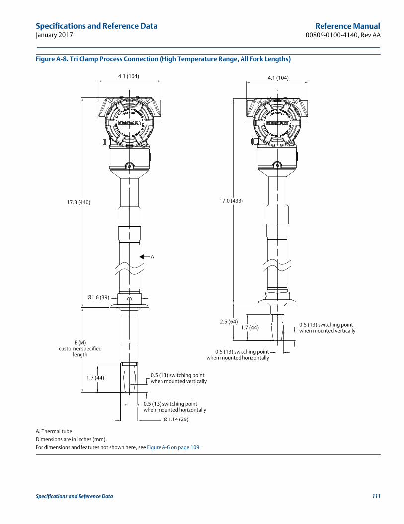
Specifications and Reference DataJanuary 2017
Reference Manual00809-0100-4140, Rev AA
Figure A-8. Tri Clamp Process Connection (High Temperature Range, All Fork Lengths)
A. Thermal tube
Dimensions are in inches (mm).
For dimensions and features not shown here, see Figure A-6 on page 109.
4.1 (104)4.1 (104)
17.3 (440)
E (M)customer specified
length
1.7 (44)
0.5 (13) switching point when mounted horizontally
0.5 (13) switching point when mounted vertically
Ø1.6 (39)
Ø1.14 (29)
A
17.0 (433)
2.5 (64)1.7 (44)
0.5 (13) switching pointwhen mounted horizontally
0.5 (13) switching point when mounted vertically
111Specifications and Reference Data

Specifications and Reference DataJanuary 2017
Reference Manual 00809-0100-4140, Rev AA
Figure A-9. Flanged Process Connection (Mid Temperature Range, Standard Length Fork)
A. Aluminum or stainless steel housing
B. Certification plate
C. Cover plate (with logo, product name, and conduit entry size)
D. External button(s) under movable plate
E. LCD display cover
F. Conduit/cable entry M20 x 1.5 or 1/2-in. ANPT
G. Housing rotation set screw. Do not unscrew all the way. Rotating the
housing, without this screw in place, can damage the internal wiring
Dimensions are in inches (mm).
4.3 (109)
5.1 (130)
4.1 (104)
LCD display
option
No LCD display
E
A
B
C, D
F
G
F
9.3 (235)
4 (102)
1.7 (44)
0.5 (13) switching point when mounted horizontally
0.5 (13) switching point when mounted vertically
Ø0.9 (23) for up to 1-in. flange;Ø0.95 (24) for up to 1-in. coated flange;Ø1.14 (29) for 11/2-in. or larger flange
112 Specifications and Reference Data
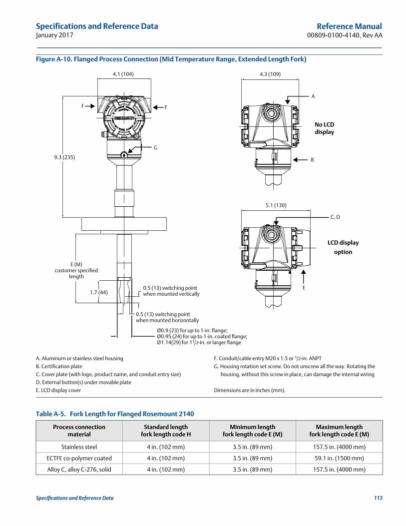
Specifications and Reference DataJanuary 2017
Reference Manual00809-0100-4140, Rev AA
Figure A-10. Flanged Process Connection (Mid Temperature Range, Extended Length Fork)
A. Aluminum or stainless steel housing
B. Certification plate
C. Cover plate (with logo, product name, and conduit entry size)
D. External button(s) under movable plate
E. LCD display cover
F. Conduit/cable entry M20 x 1.5 or 1/2-in. ANPT
G. Housing rotation set screw. Do not unscrew all the way. Rotating the
housing, without this screw in place, can damage the internal wiring
Dimensions are in inches (mm).
Table A-5. Fork Length for Flanged Rosemount 2140
4.3 (109)
5.1 (130)
4.1 (104)
LCD display
option
No LCD display
E
A
B
C, D
F
G
F
9.3 (235)
E (M)customer specified
length
1.7 (44)
0.5 (13) switching point when mounted horizontally
0.5 (13) switching point when mounted vertically
Ø0.9 (23) for up to 1-in. flange;Ø0.95 (24) for up to 1-in. coated flange;Ø1.14(29) for 11/2-in. or larger flange
Process connectionmaterial
Standard lengthfork length code H
Minimum lengthfork length code E (M)
Maximum length fork length code E (M)
Stainless steel 4 in. (102 mm) 3.5 in. (89 mm) 157.5 in. (4000 mm)
ECTFE co-polymer coated 4 in. (102 mm) 3.5 in. (89 mm) 59.1 in. (1500 mm)
Alloy C, alloy C-276, solid 4 in. (102 mm) 3.5 in. (89 mm) 157.5 in. (4000 mm)
113Specifications and Reference Data

Specifications and Reference DataJanuary 2017
Reference Manual 00809-0100-4140, Rev AA
Figure A-11. Flanged Process Connection (High Temperature Range, All Fork Lengths)
A. Thermal tubeDimensions are in inches (mm).For dimensions and features not shown here, see Figure A-9 on page 112.
4.1 (104) 4.1 (104)
A
A
16.1 (410)
4 (102)
1.7 (44)
0.5 (13) switching point when mounted horizontally
0.5 (13) switchpoint when mounted vertically0.5 (13) switching point when mounted vertically
0.5 (13) switching point when mounted vertically
0.5 (13) switching point when mounted horizontally
E (M)customer specified
length
16.1 (410)
Ø0.9 (23) for up to 1-in. flange;Ø0.95 (24) for up to 1-in. coated flange;Ø1.14 (29) for 11/2-in. or larger flange
Ø0.9 (23) for up to 1-in. flange;Ø0.95 (24) for up to 1-in. coated flange;Ø1.14 (29) for 11/2-in. or larger flange
114 Specifications and Reference Data
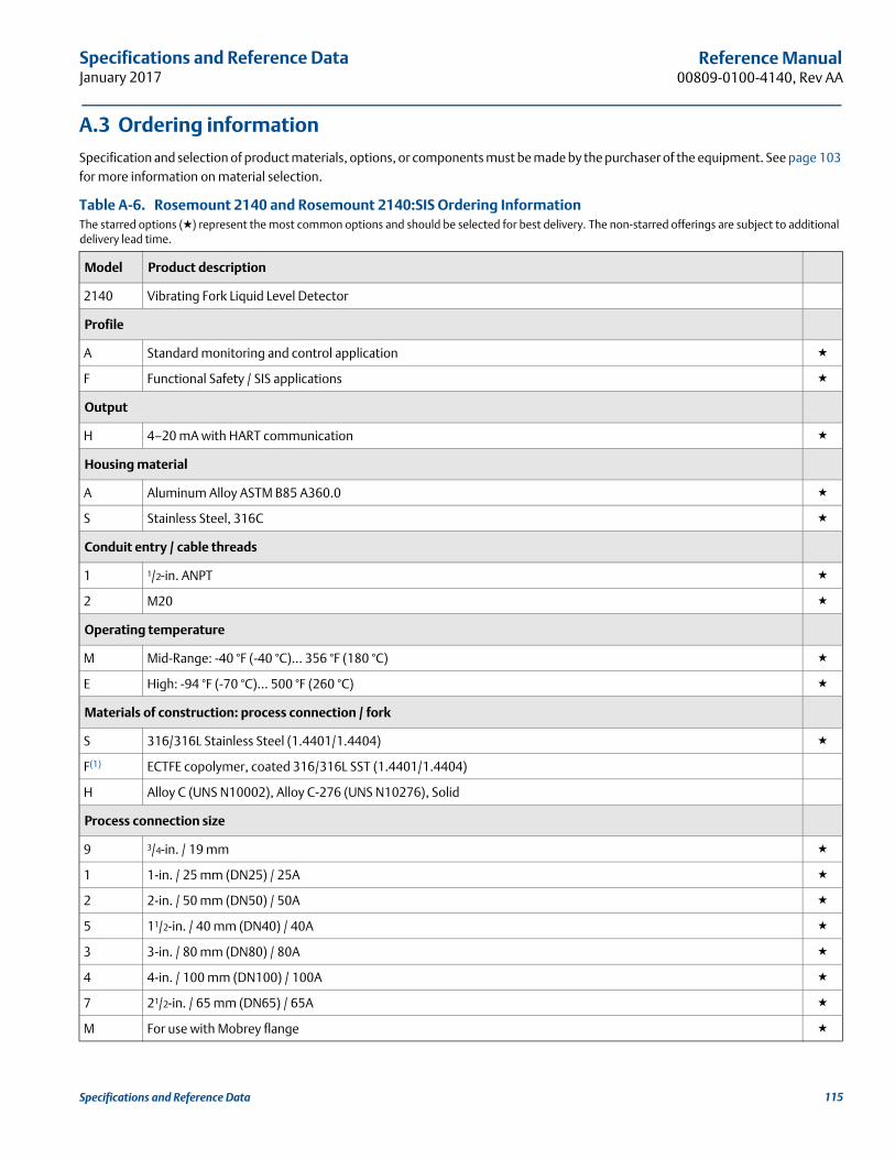
Specifications and Reference DataJanuary 2017
Reference Manual00809-0100-4140, Rev AA
A.3 Ordering information
Specification and selection of product materials, options, or components must be made by the purchaser of the equipment. See page 103 for more information on material selection.
Table A-6. Rosemount 2140 and Rosemount 2140:SIS Ordering InformationThe starred options (★) represent the most common options and should be selected for best delivery. The non-starred offerings are subject to additional delivery lead time.
Model Product description
2140 Vibrating Fork Liquid Level Detector
Profile
A Standard monitoring and control application ★
F Functional Safety / SIS applications ★
Output
H 4–20 mA with HART communication ★
Housing material
A Aluminum Alloy ASTM B85 A360.0 ★
S Stainless Steel, 316C ★
Conduit entry / cable threads
1 1/2-in. ANPT ★
2 M20 ★
Operating temperature
M Mid-Range: -40 °F (-40 °C)... 356 °F (180 °C) ★
E High: -94 °F (-70 °C)... 500 °F (260 °C) ★
Materials of construction: process connection / fork
S 316/316L Stainless Steel (1.4401/1.4404) ★
F(1) ECTFE copolymer, coated 316/316L SST (1.4401/1.4404)
H Alloy C (UNS N10002), Alloy C-276 (UNS N10276), Solid
Process connection size
9 3/4-in. / 19 mm ★
1 1-in. / 25 mm (DN25) / 25A ★
2 2-in. / 50 mm (DN50) / 50A ★
5 11/2-in. / 40 mm (DN40) / 40A ★
3 3-in. / 80 mm (DN80) / 80A ★
4 4-in. / 100 mm (DN100) / 100A ★
7 21/2-in. / 65 mm (DN65) / 65A ★
M For use with Mobrey flange ★
115Specifications and Reference Data
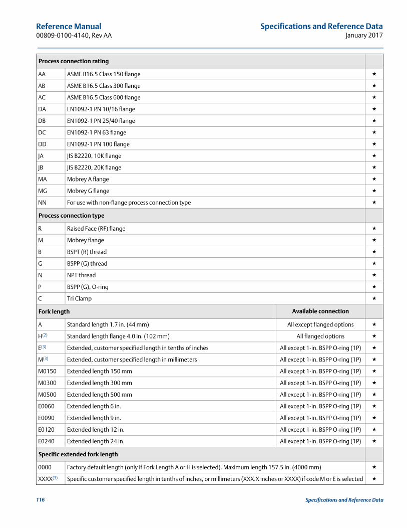
Specifications and Reference DataJanuary 2017
Reference Manual 00809-0100-4140, Rev AA
Process connection rating
AA ASME B16.5 Class 150 flange ★
AB ASME B16.5 Class 300 flange ★
AC ASME B16.5 Class 600 flange ★
DA EN1092-1 PN 10/16 flange ★
DB EN1092-1 PN 25/40 flange ★
DC EN1092-1 PN 63 flange ★
DD EN1092-1 PN 100 flange ★
JA JIS B2220, 10K flange ★
JB JIS B2220, 20K flange ★
MA Mobrey A flange ★
MG Mobrey G flange ★
NN For use with non-flange process connection type ★
Process connection type
R Raised Face (RF) flange ★
M Mobrey flange ★
B BSPT (R) thread ★
G BSPP (G) thread ★
N NPT thread ★
P BSPP (G), O-ring ★
C Tri Clamp ★
Fork length Available connection
A Standard length 1.7 in. (44 mm) All except flanged options ★
H(2) Standard length flange 4.0 in. (102 mm) All flanged options ★
E(3) Extended, customer specified length in tenths of inches All except 1-in. BSPP O-ring (1P) ★
M(3) Extended, customer specified length in millimeters All except 1-in. BSPP O-ring (1P) ★
M0150 Extended length 150 mm All except 1-in. BSPP O-ring (1P) ★
M0300 Extended length 300 mm All except 1-in. BSPP O-ring (1P) ★
M0500 Extended length 500 mm All except 1-in. BSPP O-ring (1P) ★
E0060 Extended length 6 in. All except 1-in. BSPP O-ring (1P) ★
E0090 Extended length 9 in. All except 1-in. BSPP O-ring (1P) ★
E0120 Extended length 12 in. All except 1-in. BSPP O-ring (1P) ★
E0240 Extended length 24 in. All except 1-in. BSPP O-ring (1P) ★
Specific extended fork length
0000 Factory default length (only if Fork Length A or H is selected). Maximum length 157.5 in. (4000 mm) ★
XXXX(3) Specific customer specified length in tenths of inches, or millimeters (XXX.X inches or XXXX) if code M or E is selected ★
116 Specifications and Reference Data

Specifications and Reference DataJanuary 2017
Reference Manual00809-0100-4140, Rev AA
Surface finish Available connections
1 Standard surface finish All ★
2 Mechanically polished (Ra < 0.1 μm) Tri Clamp connection Only ★
Product certifications
NA No hazardous locations certifications ★
ND ATEX, Dust Zone 20 ★
NK IECEx, Dust Zone 20 ★
G5(4) American Ordinary Locations (unclassified, safe area)
G6(5) Canadian Ordinary Locations (unclassified, safe area)
E1 ATEX Flameproof ★
E5(4) American Explosion-proof
E6(5) Canadian Explosion-proof
E7 IECEx Flameproof and Dust ★
E8 ATEX Flameproof and Dust ★
I1 ATEX Intrinsically Safe and Dust, Zone 0, 20 ★
I5 American Intrinsic Safety and Non-incendive
I6 Canadian Intrinsic Safety and Non-incendive
I7 IECEx Intrinsic Safety, Zone 0 ★
I8 ATEX Intrinsic Safety, Zone 1 ★
Typical model numbers: 2140 A H A 1 M S 1 NN B A 0000 1 NA
Options (include with the selected model number)
Calibration data certification
Q4 Certificate of functional test ★
Material traceability certification(2)(6)
Q8 Material traceability certification per EN 10204 3.1 ★
Material certification(2)(6)
Q15 NACE® MR0175 / ISO 15156 ★
Q25 NACE MR0103 ★
Product features(7)
EF0 Ready for upgrade to a Rosemount 2140 with enhanced features ★
EF1 Ready for upgrade to a Rosemount 2140:SIS with enhanced features ★
EF2 Rosemount 2140:SIS safety certified to IEC 61508 with remote proof testing, plus enhanced features enabled ★
EF3 Rosemount 2140 with enhanced features already enabled ★
117Specifications and Reference Data
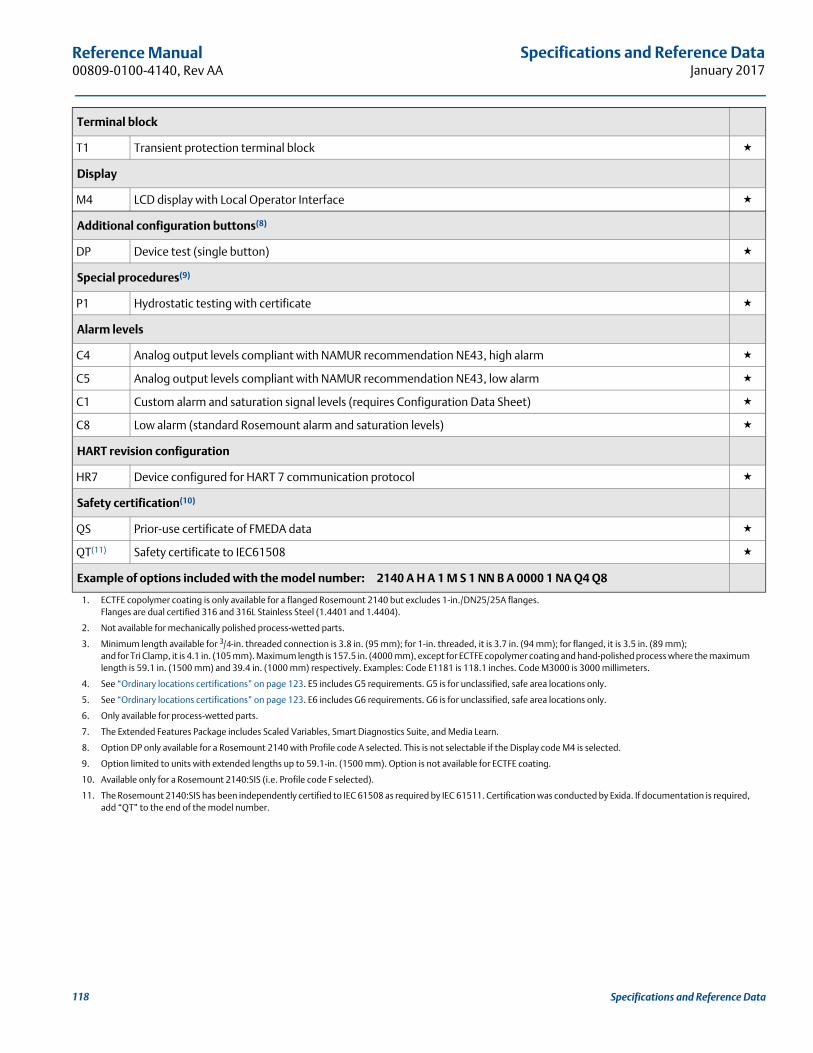
Specifications and Reference DataJanuary 2017
Reference Manual 00809-0100-4140, Rev AA
Terminal block
T1 Transient protection terminal block ★
Display
M4 LCD display with Local Operator Interface ★
Additional configuration buttons(8)
DP Device test (single button) ★
Special procedures(9)
P1 Hydrostatic testing with certificate ★
Alarm levels
C4 Analog output levels compliant with NAMUR recommendation NE43, high alarm ★
C5 Analog output levels compliant with NAMUR recommendation NE43, low alarm ★
C1 Custom alarm and saturation signal levels (requires Configuration Data Sheet) ★
C8 Low alarm (standard Rosemount alarm and saturation levels) ★
HART revision configuration
HR7 Device configured for HART 7 communication protocol ★
Safety certification(10)
QS Prior-use certificate of FMEDA data ★
QT(11) Safety certificate to IEC61508 ★
Example of options included with the model number: 2140 A H A 1 M S 1 NN B A 0000 1 NA Q4 Q8
1. ECTFE copolymer coating is only available for a flanged Rosemount 2140 but excludes 1-in./DN25/25A flanges.Flanges are dual certified 316 and 316L Stainless Steel (1.4401 and 1.4404).
2. Not available for mechanically polished process-wetted parts.
3. Minimum length available for 3/4-in. threaded connection is 3.8 in. (95 mm); for 1-in. threaded, it is 3.7 in. (94 mm); for flanged, it is 3.5 in. (89 mm);and for Tri Clamp, it is 4.1 in. (105 mm). Maximum length is 157.5 in. (4000 mm), except for ECTFE copolymer coating and hand-polished process where the maximum length is 59.1 in. (1500 mm) and 39.4 in. (1000 mm) respectively. Examples: Code E1181 is 118.1 inches. Code M3000 is 3000 millimeters.
4. See “Ordinary locations certifications” on page 123. E5 includes G5 requirements. G5 is for unclassified, safe area locations only.
5. See “Ordinary locations certifications” on page 123. E6 includes G6 requirements. G6 is for unclassified, safe area locations only.
6. Only available for process-wetted parts.
7. The Extended Features Package includes Scaled Variables, Smart Diagnostics Suite, and Media Learn.
8. Option DP only available for a Rosemount 2140 with Profile code A selected. This is not selectable if the Display code M4 is selected.
9. Option limited to units with extended lengths up to 59.1-in. (1500 mm). Option is not available for ECTFE coating.
10. Available only for a Rosemount 2140:SIS (i.e. Profile code F selected).
11. The Rosemount 2140:SIS has been independently certified to IEC 61508 as required by IEC 61511. Certification was conducted by Exida. If documentation is required, add “QT” to the end of the model number.
118 Specifications and Reference Data

Specifications and Reference DataJanuary 2017
Reference Manual00809-0100-4140, Rev AA
A.3.1 Rosemount 2140 Spares and Accessories
Specification and selection of product materials, options, or components must be made by the purchaser of the equipment.See page 103 for more information on Material Selection.
Figure A-12. Quick Release Kit
A. Quick release device for 2-in. NPT process connection
B. Seal
C. 2-in. Tri Clamp
D. Level detector with 2-in. Tri Clamp process connection
Table A-7. Rosemount 2140 Spares and AccessoriesThe starred options (★) represent the most common options and should be selected for best delivery. The non-starred offerings are subject to additional delivery lead time.
Part number Description
02100-1000-0001 Seal for 1-in. BSPP (G1A). Material: Non-asbestos BS7531 grade X carbon fiber with rubber binder ★
02100-1040-0001 Seal for 3/4-in. BSPP (G3/4A). Material: Non-asbestos BS7531 grade X carbon fiber with rubber binder ★
02100-1010-0001 1-in. BSPP to 11/2-in. (38mm) Tri Clamp. Material: 316 SS fitting. FPM/FKM ‘O’ ring ★
02100-1020-0001 2-in. (51 mm) Tri Clamp kit (vessel fitting, clamp ring, and seal). Material: 316 SST NBR Nitrile ★
02100-1060-0001 Quick Release kit (contains 2-in. Tri Clamp, seal, and quick release device for 2-in. NPT process connection) ★
The Quick Release kit is an optional set of accessories.It makes inspection, proof-testing, and servicing easierthan ever (see Table A-7 for part number).
A B
C
D
119Specifications and Reference Data

Specifications and Reference DataJanuary 2017
Reference Manual 00809-0100-4140, Rev AA
120 Specifications and Reference Data

Product CertificationsJanuary 2017
Reference Manual00809-0100-4140, Rev AA
Appendix B Product CertificationsOverview . . . . . . . . . . . . . . . . . . . . . . . . . . . . . . . . . . . . . . . . . . . . . . . . . . . . . . . . . . . . . . . . . . . . . . . . page 121European directive information . . . . . . . . . . . . . . . . . . . . . . . . . . . . . . . . . . . . . . . . . . . . . . . . . . . . page 121Ordinary locations certifications . . . . . . . . . . . . . . . . . . . . . . . . . . . . . . . . . . . . . . . . . . . . . . . . . . . . page 121Hazardous locations certifications . . . . . . . . . . . . . . . . . . . . . . . . . . . . . . . . . . . . . . . . . . . . . . . . . . page 121
B.1 Overview
This appendix contains information on European directives and hazardous locations certifications.
B.2 European directive information
A copy of the EU Declaration of Conformity can be found at the end of the Rosemount 2140 Product Certifications Manual and at Emerson.com/Rosemount.
B.3 Ordinary locations certificationsG5 USA ordinary location certification
Certificate: 16 CSA 70098390
Standards: UL 61010-1 (3rd Edition)
The level detector has been examined and tested to determine that the design meets basic electrical, mechanical, and fire protection requirements by CSA, a nationally recognized testing laboratory (NRTL) as accredited by the Federal Occupational Safety and Health Administration (OSHA). Type 4X.
G6 Canada ordinary location certification
Certificate: 16 CSA 70098390
Standards: CAN/CSA C22.2 No 61010-1-12, andANSI/ISA-12.27.01:2003
The level detector has been examined and tested to determine that the design meets basic electrical, mechanical, and fire protection requirements by CSA, a nationally recognized testing laboratory as accredited by the Standards Council of Canada (SCC). Type 4X. Single Seal.
Special conditions for use (G5 and G6)
1. To be supplied from a Class 2 or Limited Energy Source in accordance with CAN/CSA C22.2 No. 61010-1-12.
B.4 Hazardous locations certifications
B.4.1 North America and Canada
NoteFor full product approvals information, refer to the Rosemount 2140 Product Certifications Manual.
E5 USA Explosion-proof (XP)
Certificate: CSA 16CA70098990X
Standards:FM Class 3600 - 2011,FM Class 3615 - 2015, andUL 61010-1 (3rd Edition)
Markings:Class I Groups B, C and D, T5, Type 4XClass I, Zone 1, AEx db IIC T6…T2 Gb
E6 Canada Explosion-proof
Certificate: CSA 16CA70098990X
Standards:ANSI/ISA 12.27.01:2003,CSA Std. C22.2 No. 30 -M1986,CSA Std. C22.2 No.60079-0-15,CSA Std. C22.2. No.60079-1-16,CSA Std. C22.2 No. 61010-1-12, andCSA Std. C22.2 No.94-M91
Markings:Class I Groups B, C and D, T5, Type 4XEx db IIC T6…T2 Gb
Special conditions for use (X) (E5 and E6)
1. The user is to ensure the probe assembly is installed in such a way to prevent any damage due to impact or ignition source due to friction.
2. The enclosure may be given a non-standard paint finish which may constitute a potential electrostatic ignition risk. Care should be taken to protect it from external conditions conducive to the build-up of electrostatic charge on such surfaces. The enclosure must not be rubbed or cleaned with a dry cloth.
3. Flameproof joints are not intended for repair.
4. To be supplied from a Class 2 or Limited Energy Source in accordance with CAN/CSA C22.2 No. 61010-1-12.
121Product Certifications

Product CertificationsJanuary 2017
Reference Manual 00809-0100-4140, Rev AA
I5 USA Intrinsic Safety (IS) and Non-Incendive (NI)
Certificate: CSA 16CA70098990X
Standards:FM Class 3600 - 2011,FM Class 3610 - 2015, andFM Class 3611 - 2004
Markings:Class I Groups A, B, C and D, T5…T2, Type 4XClass I, Zone 0, AEx ia IIC T5…T2 GaClass I, Division 2, Groups A, B, C, and Dwhen connected using installation drawing 71097/1387
I6 Canada Intrinsic Safety and Non-Incendive
Certificate: CSA 16CA70098990X
Standards:ANSI/ISA 12.27.01:2003,CSA Std. C22.2 No. 157 -92,CSA Std. C22.2 No.60079-0-15,CSA Std. C22.2. No.60079-11-14, andCSA Std. C22.2 No.213-M1987
Markings:Class I Groups A, B, C and D, T5…T2, Type 4XEx ia IIC T5…T2 GaClass I, Division 2, Groups A, B, C, and Dwhen connected using installation drawing 71097/1387
Special conditions for use (X) (I5 and I6)
1. The equipment, when fitted with the transient suppression terminal block, is not capable of withstanding the 500 volt insulation test. This must be taken into account when installing the equipment.
2. The enclosure may be made of aluminum alloy and given a protective polyurethane paint finish. However, care should be taken to protect it from impact or abrasion if located in Zone 0.
3. The enclosure may be given a non-standard paint finish which may constitute a potential electrostatic ignition risk. Care should be taken to protect it from external conditions conducive to the build-up of electrostatic charge on such surfaces. The enclosure must not be rubbed or cleaned with a dry cloth.
B.4.2 Europe
NoteFor full product approvals information, refer to the Rosemount 2140 Product Certifications Manual.
E1 ATEX Flameproof
Certificate: Dekra 16ATEX0082X
Standards:EN60079-0:2012+A11:2013,EN60079-1:2014, andEN60079-26:2015
Markings: II 1/2 G, Ex db IIC T6...T2 Ga/Gb
ND ATEX Dust
Certificate: Baseefa 16ATEX0137X
Standards:EN60079-0:2012+A11:2013 and EN60079-31:2014
Markings:
II 1 D Ex ta IIIC (T92°C…T272°C) (T500100°C…T500280°C) Da
E8 Combines E1 and ND
I1 ATEX Intrinsically Safe and Dust (Zone 0, 20)
Certificates:Baseefa 16ATEX0136X and Baseefa 16ATEX0137X
Standards:EN60079-0:2012+A11:2013,EN60079-11:2012,EN60079-26:2015, andEN60079-31:2014
Markings: II 1 G, Ex ia IIC T5...T2 Ga II 1 D Ex ta IIIC (T92...T272°C) (T500100°C...T500280°C) Da
(I1 includes the ND approval)
I8 ATEX Intrinsically Safe (Zone 1)
Certificate: Baseefa 16ATEX0136X
Standards:EN60079-0:2012+A11:2013,EN60079-11:2012, and EN60079-26:2015
Markings: II 1/2 G, Ex ia IIC T5...T2 Ga/Gb
122 Product Certifications

Product CertificationsJanuary 2017
Reference Manual00809-0100-4140, Rev AA
Special conditions for use (X) (E1 and E8)
1. The user is to ensure the probe assembly is installed in such a way to prevent any damage due to impact or ignition source due to friction.
2. Non-standard paint options may cause risk from electrostatic discharge. Avoid installations that could cause electrostatic build-up of painted surfaces, and only clean the painted surfaces with a damp cloth. If paint is ordered through a special option code, contact the manufacturer for more information.
3. Flameproof joints are not intended for repair.
Special conditions for use (X) (I1 and I8)
1. The equipment, when fitted with the transient suppression terminal block, is not capable of withstanding the 500 volt insulation test. This must be taken into account when installing the equipment.
2. The enclosure may be made of aluminum alloy and given a protective polyurethane paint finish. However, care should be taken to protect it from impact or abrasion if located in Zone 0.
3. The enclosure may be given a non-standard paint finish which may constitute a potential electrostatic ignition risk. Care should be taken to protect it from external conditions conducive to the build-up of electrostatic charge on such surfaces. The enclosure must not be rubbed or cleaned with a dry cloth.
4. The enclosure may be given a non-standard paint finish which may constitute a potential electrostatic ignition risk. Care should be taken to protect it from external conditions conducive to the build-up of electrostatic charge on such surfaces. The enclosure must not be rubbed or cleaned with a dry cloth.
Special conditions for use (X) (ND, E8, and I1)
1. Cable entries must maintain the ingress protection rating of the enclosure to at least IP66.
2. Unused cable entries must be filled with suitable blanking plugs which maintain the ingress protection of the enclosure to at least IP66.
3. Cable entries and blanking plugs must be suitable for the ambient temperature of the equipment and be capable of withstanding a 7J impact test.
B.4.3 International
NoteFor full product approvals information, refer to the Rosemount 2140 Product Certifications Manual.
E7 IECEx Flameproof and Dust
Certificates: IECEx DEK 16.0040X and IECEx BAS 16.0106X
Standards:IEC60079-0:2011,IEC60079-1:2014,IEC60079-26:2014, andIEC60079-31:2013
Markings:Ex db IIC T6...T2 Ga/GbEx ta IIIC (T92°C…T272°C) (T500100°C…T500280°C) Da
(E7 also includes the NK approval)
I7 IECEx Intrinsically Safe
Certificate: IECEx BAS 16.0105X
Markings:Ex ia IIC T5...T2 Ga
Standards:IEC60079-0:2011 and IEC60079-11:2011
NK IECEx Dust
Certificate: IECEx BAS 16.0106X
Standards:IEC60079-0:2011 and IEC60079-31:2013
Markings:Ex ta IIIC (T92°C…T272°C) (T500100°C…T500280°C) Da
Special conditions for use (X) (E7)
1. The user is to ensure the probe assembly is installed in such a way to prevent any damage due to impact or ignition source due to friction.
2. Non-standard paint options may cause risk from electrostatic discharge. Avoid installations that could cause electrostatic build-up of painted surfaces, and only clean the painted surfaces with a damp cloth. If paint is ordered through a special option code, contact the manufacturer for more information.
3. Flameproof joints are not intended for repair.
123Product Certifications
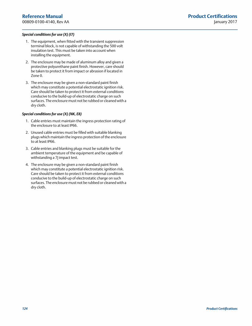
Product CertificationsJanuary 2017
Reference Manual 00809-0100-4140, Rev AA
Special conditions for use (X) (I7)
1. The equipment, when fitted with the transient suppression terminal block, is not capable of withstanding the 500 volt insulation test. This must be taken into account when installing the equipment.
2. The enclosure may be made of aluminum alloy and given a protective polyurethane paint finish. However, care should be taken to protect it from impact or abrasion if located in Zone 0.
3. The enclosure may be given a non-standard paint finish which may constitute a potential electrostatic ignition risk. Care should be taken to protect it from external conditions conducive to the build-up of electrostatic charge on such surfaces. The enclosure must not be rubbed or cleaned with a dry cloth.
Special conditions for use (X) (NK, E8)
1. Cable entries must maintain the ingress protection rating of the enclosure to at least IP66.
2. Unused cable entries must be filled with suitable blanking plugs which maintain the ingress protection of the enclosure to at least IP66.
3. Cable entries and blanking plugs must be suitable for the ambient temperature of the equipment and be capable of withstanding a 7J impact test.
4. The enclosure may be given a non-standard paint finish which may constitute a potential electrostatic ignition risk. Care should be taken to protect it from external conditions conducive to the build-up of electrostatic charge on such surfaces. The enclosure must not be rubbed or cleaned with a dry cloth.
124 Product Certifications

Field Communicator Menu TreeJanuary 2017
Reference Manual00809-0100-4140, Rev AA
Appendix C Field Communicator Menu Tree
C.1 Field Communicator menu trees
Figure C-1. Rosemount 2140 Field Communicator Menu Tree (Overview)
1. Overview
2. Configure
1. Device Status
1. Identification
2. Comm Status
2. Revision Numbers3. Alarm Levels
3. Sensor State– 1.0=Wet/0.0=Dry4. 1.0=On/0.0=Off
4. Security5. Upgrade Device
1. HART Universal Revision2. Field Device3. Software4. Hardware5. Device Driver Revision
1. Tag
1. Comminication Change
2. Long Tag (*1)3. Model4. Transmitter Serial Num.5. Device ID6. Date7. Descriptor8. Message9. Model Numbers10. Device Image
5. Analog Output6. Upper Range Value7. Lower Range Value8. Device Information
1. Model
1. Alarm Direction2. High Alarm3. High Saturation4. Low Saturation5. Low Alarm
1. Security Switch Status2. External Buttons3. Configuration Buttons4. HART Lock (*1)
2. Options3. Transmitter Serial Num.4. Upgrade
5. LOI Password Protection
3. Service Tools
1. Model Number 12. Model Number 2
(*1) Available only when operating as a HART7 device.
page 126
page 128
125Field Communicator Menu Tree

Field Communicator Menu TreeJanuary 2017
Reference Manual 00809-0100-4140, Rev AA
Figure C-2. Rosemount 2140 Field Communicator Menu Tree (Configure Part One)
1. Basic Setup2. Display3. Process Alerts (*2)4. Scaled Variable (*1)5. Burst Mode6. Power Advisory (*2)
1. Guided Setup
2. Manual Setup
3. Alert Setup
1. Operation2. Analog Output3. Scaled Variable (*1)4. Device Temperature5. Display6. HART7. Security8. Frequency Profiling (*2)9. Device Information
1. Output State2. Sensor State3. Sensor Frequency4. Scaled Variable (*1)5. Electronics Temperature6. Terminal Voltage7. Percent of Range8. Analog Output9. Review Parameters at Start.
1. Type: Custom (*3) 2. Alarm Direction3. High Alarm4. High Saturation5. Low Saturation6. Low Alarm7. Config Alarm/Sat Levels
1. Application2. Device Test (*5)3. Sensor
1. Output State2. Sensor State3. Sensor Frequency4. Scaled Variable (*1)5. Electronics Temperature6. Terminal Voltage
3. Service Tools
1. Sensor Operating Mode2. Sensor Output Delay3. Media Density4. Learnt (*2)5. Media Learn (*2)
1. Duration2. Start-up Device Test (*9)
1. Allowable Change in Dry Fork Frequency
2. Sensor Fault Delay
1. Overview
2. Configure
(*3) Types can be “NAMUR”, “Rosemount ”, or “Custom”.
(*4) Available only when operating as a HART7 device.
(*6) Available only when operating as a HART5 device.
(*5) Proof Test on Rosemount 2140:SIS.
(*7) Start-up Proof Test on Rosemount 2140:SIS.
1. Burst Message 1 (*4)2. Message 1 Content (*4)
1. Burst Message 1 (*6)
2. Message 1 Content (*6)
3. Message 1 Variables (*6)
1. Power Advisory Settings2. Loop Power Characteriz.
1. Terminal Voltage2. Terminal Voltage Derivation Limit3. Action4. Reset Alert
1. Resistance2. Power Supply3. Characterize Loop
1. First and Trigger Variable2. Secondary Variable3. Tertiary Variable4. Quaternary Variable
1. Primary Variable2. Upper Range Value3. Lower Range Value
1. PV Upper Limit2. PV Lower Limit3. PV Minimum Span
1. Analog Output2. Percent of Range
1. Mode Setup2. Set Range Points3. Sensor Limits 4. Readings
5. Alarm/Saturation Levels
1. Current Output Type2. Current Output Operating Mode
3. Custom Off Current4. Custom On Current
1. SV Data Points2. SV Units3. SV Transfer Function
5. Scaled Variable
1. Electronics Temperature2. Status (*4)3. Unit4. Maximum5. Minimum
1. Output State2. Sensor State3. Sensor Frequency4. Scaled Variable (*1)5. Electronics Temperature6. Terminal Voltage7. Percent of Range8. Analog Output9. Review Parameters at St.
1. SV Data Points2. SV Units3. SV Transfer Function4. SV Linear Offset5. Scaled Variable
1. Configure Alert2. Alert Mode3. Sensor State4. High Alert Value5. Low Alert Value
1. Configure Alert2. Alert Mode3. Output State4. High Alert Value5. Low Alert Value
1. Configure Alert2. Alert Mode3. Sensor Frequency4. High Alert Value5. Low Alert Value
1. Configure Alert2. Alert Mode3. Scaled Variable4. High Alert Value5. Low Alert Value
1. Configure Alert2. Alert Mode3. Electronics Temperature4. Low Alert Value5. Low Alert Value
1. Configure Alert2. Alert Mode3. Terminal Voltage4. High Alert Value5. Low Alert Value
(*1) Available on a Rosemount 2140 with the Extended Features Package (EFP).
(*2) Available with the Extended Features Package (EFP) on a Rosemount 2140 or Rosemount 2140:SIS. .
4. SV Linear Offset
page 125
page 128
page 127
126 Field Communicator Menu Tree
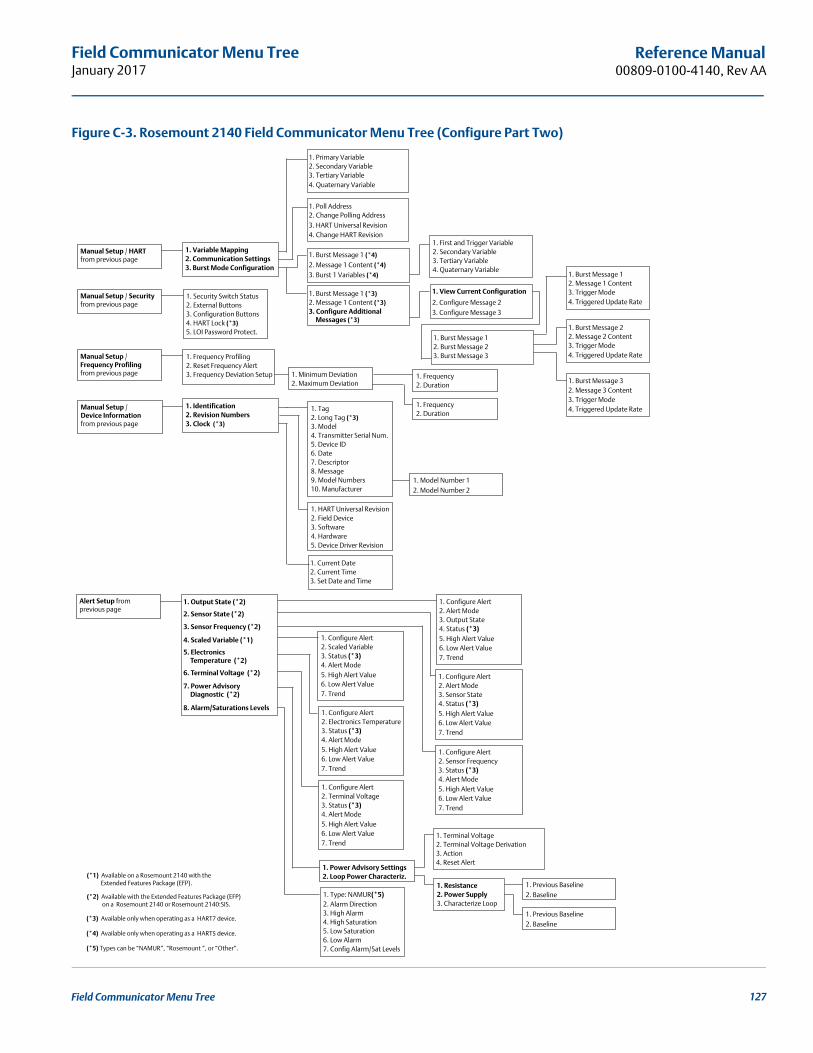
Field Communicator Menu TreeJanuary 2017
Reference Manual00809-0100-4140, Rev AA
Figure C-3. Rosemount 2140 Field Communicator Menu Tree (Configure Part Two)
Alert Setup from previous page
Manual Setup / HARTfrom previous page
Manual Setup / Securityfrom previous page
1. Output State (*2)
3. Sensor Frequency (*2)
2. Sensor State (*2)
4. Scaled Variable (*1)
5. Electronics Temperature (*2)
6. Terminal Voltage (*2)
7. Power Advisory Diagnostic (*2)
8. Alarm/Saturations Levels
1. Variable Mapping2. Communication Settings3. Burst Mode Configuration
1. Primary Variable2. Secondary Variable3. Tertiary Variable4. Quaternary Variable
1. Poll Address2. Change Polling Address3. HART Universal Revision4. Change HART Revision
1. Burst Message 1 (*3)2. Message 1 Content (*3)3. Configure Additional Messages (*3)
1. View Current Configuration
2. Configure Message 23. Configure Message 3
1. Burst Message 12. Burst Message 23. Burst Message 3
1. Burst Message 1 (*4)
2. Message 1 Content (*4)
3. Burst 1 Variables (*4)
1. Type: NAMUR(*5)2. Alarm Direction3. High Alarm4. High Saturation5. Low Saturation6. Low Alarm7. Config Alarm/Sat Levels
1. Power Advisory Settings2. Loop Power Characteriz.
1. Terminal Voltage2. Terminal Voltage Derivation3. Action4. Reset Alert
1. Resistance2. Power Supply3. Characterize Loop
1. Burst Message 12. Message 1 Content3. Trigger Mode4. Triggered Update Rate
1. Burst Message 22. Message 2 Content3. Trigger Mode4. Triggered Update Rate
1. Burst Message 32. Message 3 Content3. Trigger Mode4. Triggered Update Rate
1. Security Switch Status2. External Buttons3. Configuration Buttons4. HART Lock (*3)5. LOI Password Protect.
Manual Setup / Frequency Profilingfrom previous page
1. Frequency Profiling2. Reset Frequency Alert3. Frequency Deviation Setup 1. Minimum Deviation
2. Maximum Deviation
Manual Setup /Device Informationfrom previous page
1. Identification2. Revision Numbers3. Clock (*3)
1. HART Universal Revision2. Field Device3. Software4. Hardware5. Device Driver Revision
1. Tag2. Long Tag (*3)3. Model4. Transmitter Serial Num.5. Device ID6. Date7. Descriptor8. Message9. Model Numbers10. Manufacturer
1. Current Date2. Current Time3. Set Date and Time
1. Model Number 12. Model Number 2
1. Configure Alert2. Alert Mode3. Output State4. Status (*3)
6. Low Alert Value7. Trend
5. High Alert Value
1. Configure Alert2. Alert Mode3. Sensor State4. Status (*3)
6. Low Alert Value7. Trend
5. High Alert Value
1. Configure Alert
3. Status (*3) 2. Sensor Frequency
4. Alert Mode
6. Low Alert Value7. Trend
5. High Alert Value
1. Configure Alert2. Scaled Variable3. Status (*3)4. Alert Mode
6. Low Alert Value7. Trend
5. High Alert Value
1. Configure Alert2. Electronics Temperature3. Status (*3) 4. Alert Mode
6. Low Alert Value7. Trend
5. High Alert Value
1. Configure Alert2. Terminal Voltage3. Status (*3)4. Alert Mode
6. Low Alert Value7. Trend
5. High Alert Value
(*5) Types can be “NAMUR”, “Rosemount ”, or “Other”.
1. Previous Baseline2. Baseline
1. Previous Baseline2. Baseline
(*3) Available only when operating as a HART7 device.
(*4) Available only when operating as a HART5 device.
1. First and Trigger Variable2. Secondary Variable3. Tertiary Variable4. Quaternary Variable
(*1) Available on a Rosemount 2140 with the Extended Features Package (EFP).
(*2) Available with the Extended Features Package (EFP) on a Rosemount 2140 or Rosemount 2140:SIS.
1. Frequency2. Duration
1. Frequency2. Duration
127Field Communicator Menu Tree
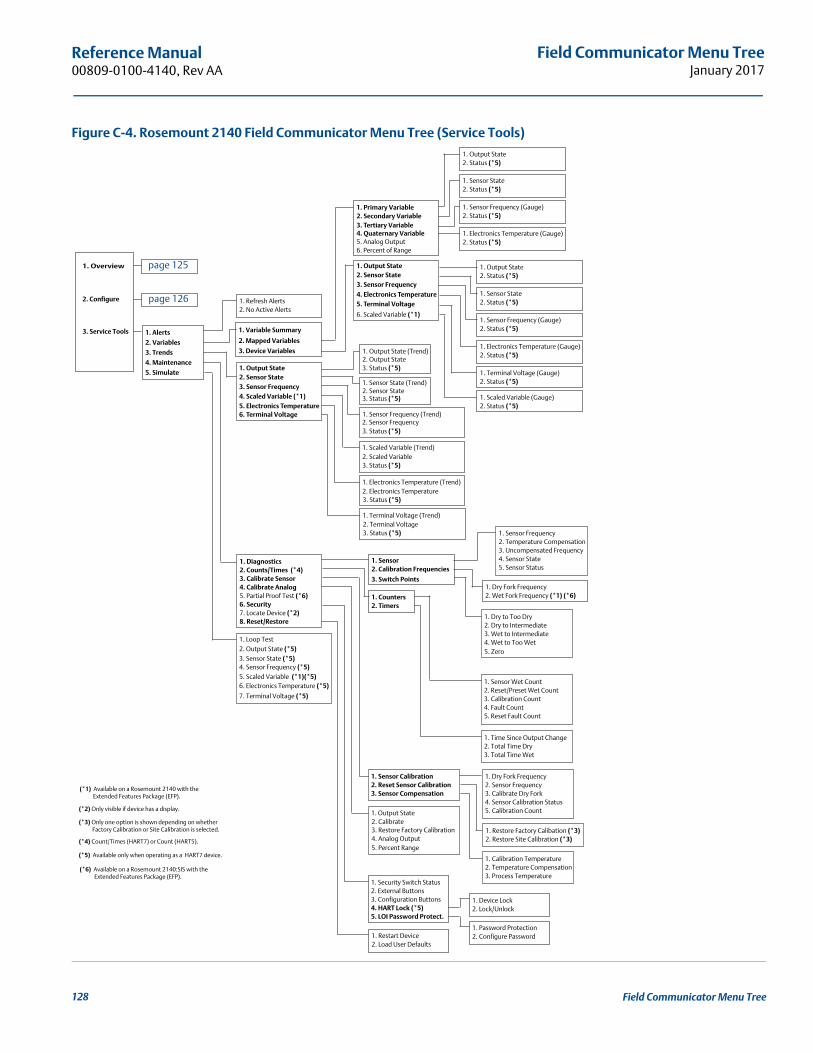
Field Communicator Menu TreeJanuary 2017
Reference Manual 00809-0100-4140, Rev AA
Figure C-4. Rosemount 2140 Field Communicator Menu Tree (Service Tools)
1. Alerts
2. Variables
3. Trends
4. Maintenance
5. Simulate
3. Service Tools
1. Overview
2. Configure 1. Refresh Alerts2. No Active Alerts
1. Sensor2. Calibration Frequencies
3. Switch Points
1. Counters2. Timers
1. Output State2. Sensor State3. Sensor Frequency
6. Scaled Variable (*1)
5. Analog Output6. Percent of Range
4. Electronics Temperature5. Terminal Voltage
1. Diagnostics2. Counts/Times (*4)3. Calibrate Sensor4. Calibrate Analog5. Partial Proof Test (*6) 6. Security7. Locate Device (*2)8. Reset/Restore
2. Sensor State1. Output State
3. Sensor Frequency4. Scaled Variable (*1)5. Electronics Temperature6. Terminal Voltage
(*2) Only visible if device has a display.
(*4) Count/Times (HART7) or Count (HART5).
(*3) Only one option is shown depending on whether Factory Calibration or Site Calibration is selected.
1. Sensor Frequency2. Temperature Compensation3. Uncompensated Frequency4. Sensor State5. Sensor Status
1. Dry to Too Dry2. Dry to Intermediate3. Wet to Intermediate4. Wet to Too Wet5. Zero
1. Sensor Wet Count2. Reset/Preset Wet Count3. Calibration Count4. Fault Count5. Reset Fault Count
1. Dry Fork Frequency2. Sensor Frequency3. Calibrate Dry Fork4. Sensor Calibration Status5. Calibration Count
1. Time Since Output Change2. Total Time Dry3. Total Time Wet
1. Calibration Temperature2. Temperature Compensation3. Process Temperature
1. Sensor Calibration2. Reset Sensor Calibration3. Sensor Compensation
1. Output State
3. Restore Factory Calibration4. Analog Output5. Percent Range
1. Security Switch Status2. External Buttons3. Configuration Buttons4. HART Lock (*5)5. LOI Password Protect.
1. Restart Device2. Load User Defaults
1. Device Lock2. Lock/Unlock
1. Password Protection2. Configure Password
1. Restore Factory Calibation (*3)2. Restore Site Calibration (*3)
1. Loop Test2. Output State (*5)3. Sensor State (*5)4. Sensor Frequency (*5)5. Scaled Variable (*1)(*5)6. Electronics Temperature (*5)
7. Terminal Voltage (*5)
1. Variable Summary
2. Mapped Variables
3. Device Variables
1. Primary Variable2. Secondary Variable3. Tertiary Variable4. Quaternary Variable
(*1) Available on a Rosemount 2140 with the Extended Features Package (EFP).
(*6) Available on a Rosemount 2140:SIS with the Extended Features Package (EFP).
(*5) Available only when operating as a HART7 device.
1. Electronics Temperature (Gauge)2. Status (*5)
1. Sensor Frequency (Gauge)2. Status (*5)
1. Sensor State2. Status (*5)
1. Output State2. Status (*5)
1. Electronics Temperature (Gauge)2. Status (*5)
1. Sensor Frequency (Gauge)2. Status (*5)
1. Sensor State2. Status (*5)
1. Output State2. Status (*5)
1. Terminal Voltage (Gauge)2. Status (*5)
1. Scaled Variable (Gauge)2. Status (*5)
2. Scaled Variable1. Scaled Variable (Trend)
3. Status (*5)
1. Sensor Frequency (Trend)2. Sensor Frequency3. Status (*5)
1. Sensor State (Trend)2. Sensor State3. Status (*5)
1. Output State (Trend)2. Output State3. Status (*5)
1. Electronics Temperature (Trend)
3. Status (*5)
1. Terminal Voltage (Trend)
3. Status (*5)
2. Electronics Temperature
2. Terminal Voltage
1. Dry Fork Frequency2. Wet Fork Frequency (*1) (*6)
2. Calibrate
page 125
page 126
128 Field Communicator Menu Tree

Local Operator InterfaceJanuary 2017
Reference Manual00809-0100-4140, Rev AA
Appendix D Local Operator Interface
D.1 LOI menu trees
Figure D-1. LOI Menu Tree (Main)
LOI MENUVIEW CONFIGTESTDISPLAYCALIBRATUNITSRERANGE (*1)EXTENDED MENUEXIT MENU
TEST
PROOF TEST (*3)LOOP TESTBACK TO MENUEXIT MENU
DISPLAYOUTPUT (on/off)STATE (on/off)
BACK TO MENUEXIT MENU
FREQ (on/off)RANGE % (on/off)
TEMP (on/off)ANALOG (on/off)VOLTAG (on/off)STARTUP (on/off)
RERANGEENTER VALUESAPPLY VALUESBACK TO MENUEXIT MENU
EXTENDED MENUCALIBRATSENSORMEDIAASSIGN PV (*4)SCALED VARIAB (*4)DAMPING (*4)TAG
VIEW CONFIGTAGMODELIS PV (*4)S UNITS (*4)T UNITS (*9)OPMODEDENSTYF DLYO DLYAOMODE (*6)OFF MA (*7)ON MA (*7)S-STARTURV (*1)LRV (*1)DAMPING (*4)HIALRM (*8)LOALRM (*8)HI SAT (*1)LO SAT (*1)ALARMSECUREBACK TO MENUEXIT MENU
LOOP TESTSET 4MASET 20MA
BACK TO MENUEXIT MENU
SET CUSTOMEND LOOP TEST
ENTER VALUESLRVURVBACK TO MENUEXIT MENU
APPLY VALUESLRVURVBACK TO MENUEXIT MENU
SCALED (*4) (on/off)
DEVICE TEST (*2)
ALARM VALUES (*5)
BACK TO MENUEXIT MENU
ALRM SAT VALUES (*4)ANALOG OUTPUTPASSWORDSELF TESTSIMULATEHART REV
(*2) Not available for Rosemount 2140:SIS.
(*3) Available for Rosemount 2140:SIS.
(*4) Available for Rosemount 2140 with extended features package.
(*5) Not available for Rosemount 2140 with extended features package.
(*6) Displayed only when the PV is mapped to the Output State device variable.
(*7) Displayed only when the Current Output Operating Mode device variable is set to Custom and the PV is mapped to the Output State device variable.
(*8) Alarm level shown depends on setting of the hardware alarm level switch.
(*9) Available on SI units only.
(*1) Available only when the Primary Variable (”PV”) is mapped to the Sensor Frequency or Scaled Variable device variables.
129Local Operator Interface

Local Operator InterfaceJanuary 2017
Reference Manual 00809-0100-4140, Rev AA
Figure D-2. LOI Menu Tree (Extended Menu)
EXTENDED MENUCALIBRATSENSORMEDIAASSIGN PV (*1)SCALED VARIAB (*1)DAMPING (*1)TAG
CALIBRATSENSOR CALANALOG TRIM
BACK TO MENUEXIT MENU
PARAMETR RECALL PARAMETR RECALLDRY RECALLUSER RECALLFACTORY RECALL
BACK TO MENUEXIT MENU
ANALOG RECALLSENSOROPERATE MODEOUTPUT DELAY
BACK TO MENUEXIT MENU
FAULT DELAY
MEDIADENSTYLEARN (*3)BACK TO MENUEXIT MENU
ASSIGN PVOUTPUT SET PVFREQ SET PV
BACK TO MENUEXIT MENU
SCALED SET PV
SCALED VARIABVIEW SCALEDCONFIG SCALEDBACK TO MENUEXIT MENU
ALARM SAT VALUESROSEMNT VALUESNAMUR VALUES
BACK TO MENUEXIT MENU
CUSTOM VALUES
ANALOG OUTPUTOPERATE MODEOUTPUT MODE
BACK TO MENUEXIT MENU
CUSTOM OFFCUSTOM ON
PASSWORDPASSWD ENABLECHANGE PASSWDBACK TO MENUEXIT MENU
DEVICE TEST
START-UPBACK TO MENUEXIT MENU
DURATION
HART REVHART7 REVHART5 REVBACK TO MENUEXIT MENU
SIMULATESIMULATE OUTPUTSIMULATE STATE
BACK TO MENUEXIT MENU
SIMULATE FREQSIMULATE SCALED (*1)SIMULATE TEMPSIMULATE VOLTAGEND SIMUL
CUSTOM VALUESHIGH ALARMLOW ALARM
BACK TO MENUEXIT MENU
HIGH SATLOW SAT
ALARM VALUESROSEMNT VALUESNAMUR VALUES
BACK TO MENUEXIT MENU
CUSTOM VALUES CUSTOM VALUESHIGH ALARMLOW ALARMBACK TO MENUEXIT MENU
ALARM VALUES (*2)
BACK TO MENUEXIT MENU
ALRM SAT VALUES (*1)ANALOG OUTPUTPASSWORDDEVICE TESTSIMULATEHART REV
(*2) Not available for a Rosemount 2140 with the extended features package.
(*3) Available only with the extended features package.
(*1) Available only for a Rosemount 2140 with the extended features package.
130 Local Operator Interface

Local Operator InterfaceJanuary 2017
Reference Manual00809-0100-4140, Rev AA
D.2 Number entryFloating-point numbers can be entered with the LOI. All eight number locations on the top line can be used for number entry. Refer to Table 2-1 on page 8 for LOI button operation. Table D-1 is an example for changing a value of “-0000022” to “000011.2”.
Table D-1. Changing Value Example
NoteIt is possible to move backwards in the number by scrolling to the left arrow symbol and pressing enter. The negative symbol is only allowed in the left most position. Numbers can be entered in scientific notation by placing an “E” in the 7th position.
Step InstructionCurrent position
(indicated by underline)
1 When the number entry begins, the left-most position is the selected position. In this example, the negative symbol, “-“, will be flashing on the screen.
-0000022
2 Press the scroll button until the “0” is blinking on the screen in the selected position.
00000022
3 Press the enter button to select the “0” as an entry. The second digit from the left will be blinking.
00000022
4 Press the enter button to select “0” for second digit. The third digit from the left will be blinking.
00000022
5 Press the enter button to select “0” for the third digit. The fourth digit from the left will now be blinking.
00000022
6 Press the enter button to select “0” for the fourth digit. The fifth digit from the left will now be blinking.
00000022
7 Press scroll to navigate through the numbers until the “1” is on the screen.
00001022
8 Press the enter button to select the “1” for the fifth digit. The sixth digit from the left will now be blinking.
00001022
9 Press scroll to navigate through the numbers until the “1”, is on the screen.
00001122
10 Press the enter button to select the “1” for the sixth digit. The seventh digit from the left will now be blinking.
00001122
11 Press scroll to navigate through the numbers until the decimal, “.”, is on the screen.
000011.2
12 Press the enter button to select the decimal, “.”, for the seventh digit. After pressing enter, all digits to the right of the decimal will now be zero. The eighth digit from the left will now be blinking.
000011.0
13 Press the scroll button to navigate through the numbers until the “2”, is on the screen.
000011.2
14 Press the enter button to select the “2” for the eighth digit. The number entry will be complete and a “SAVE” screen will be shown.
000011.2
131Local Operator Interface
Local Operator InterfaceJanuary 2017
Reference Manual 00809-0100-4140, Rev AA
D.3 Text entryText can be entered using the LOI. Depending on the edited item, up to eight locations on the top line can be used for text entry.
Text entry follows the same rules as the number entry rules in “Number entry” on page 131, except the following characters are available in all locations: A to Z, 0 to 9, -, /, and space.
NoteIf the current text contains a character the LOI cannot display, it will be shown as an asterisk “*”.
132 Local Operator Interface


Reference Manual00809-0100-4140, Rev AA
January 2017
Global Headquarters
Emerson Automation Solutions 6021 Innovation Blvd.Shakopee, MN 55379, USA+1 800 999 9307 or +1 952 906 8888+1 952 949 7001 [email protected]
North America Regional OfficeEmerson Automation Solutions 8200 Market Blvd.Chanhassen, MN 55317, USA
+1 800 999 9307 or +1 952 906 8888+1 952 949 7001 [email protected]
Latin America Regional OfficeEmerson Automation Solutions 1300 Concord Terrace, Suite 400Sunrise, FL 33323, USA
+1 954 846 5030+1 954 846 [email protected]
Europe Regional OfficeEmerson Automation Solutions Europe GmbHNeuhofstrasse 19a P.O. Box 1046CH 6340 BaarSwitzerland
+41 (0) 41 768 6111+41 (0) 41 768 6300 [email protected]
Asia Pacific Regional OfficeEmerson Automation Solutions Asia Pacific Pte Ltd
Linkedin.com/company/Emerson-Automation-Solutions
Twitter.com/Rosemount_News
Facebook.com/Rosemount
1 Pandan CrescentSingapore 128461
+65 6777 8211+65 6777 0947 [email protected]
Middle East and Africa Regional OfficeEmerson Automation Solutions Emerson FZE P.O. Box 17033Jebel Ali Free Zone - South 2Dubai, United Arab Emirates
+971 4 8118100+971 4 8865465 [email protected]
Youtube.com/user/RosemountMeasurement
Google.com/+RosemountMeasurement
Standard Terms and Conditions of Sale can be found at: www.Emerson.com/en-us/Terms-of-UseThe Emerson logo is a trademark and service mark of Emerson Electric Co.AMS, Rosemount and Rosemount logotype are trademarks of Emerson.HART is a registered trademark of the FieldComm Group.ROCKWOOL is a registered trademark of ROCKWOOL International A/S and/or its affiliates.NEMA is the registered trademark and service mark of the National Electrical Manufacturers Association.All other marks are the property of their respective owners.© 2017 Emerson. All rights reserved.