manual - static.e-xina.com
TRANSCRIPT

IRI1-ER
PROTECTION TECHNOLOGYMADE SIMPLEHighTECH Line
STABILIZED EARTH FAULT CURRENT RELAY
Original User ManualEnglish
Revision: B
MANUAL
STABILIZED EARTH FAULT CURRENT RELAY

SEG Electronics GmbH Manual IRI1-ER
2 DOK-TD-IRI1-ER, Rev. B
SEG Electronics GmbH reserves the right to update any portion of this publication at any time. Information provided by SEG Electronics GmbH is believed to be correct and reliable.
However, no responsibility is assumed by SEG Electronics GmbH unless otherwise expressly undertaken.
© SEG Electronics 1994–2020

Manual IRI1-ER SEG Electronics GmbH
DOK-TD-IRI1-ER, Rev. B 3
Content
1. Summary ....................................................................................................... 4
2. Applications ................................................................................................. 5
3. Characteristics and features ....................................................................... 6
4. Design ........................................................................................................... 7 4.1 Connections ........................................................................................................................ 7
4.1.1 Analog inputs ................................................................................................................... 8 4.1.2 Output relays ................................................................................................................... 8
4.2 Front plate ........................................................................................................................... 8 4.2.1 LEDs ................................................................................................................................ 9 4.2.2 DIP-switches ................................................................................................................... 9 4.2.3 <RESET>-push button .................................................................................................... 9
4.3 Code jumper ........................................................................................................................ 9
5. Working principle ....................................................................................... 10
6. Operations and settings ............................................................................ 12 6.1 Layout of the operating elements ...................................................................................... 12 6.2 Setting of the pick-up value for the differential current ID .................................................. 12
6.2.1 Indication of fault ........................................................................................................... 12 6.3 Reset ................................................................................................................................. 13
6.3.1 Reset by pressing the <RESET>-push-button .............................................................. 13 6.3.2 Automatic reset ............................................................................................................. 13
6.4 Calculation of the tripping current and the stabilizing resistance .................................... 14 6.4.1 Sample calculation - alternator ...................................................................................... 14 6.4.2 Example calculation - transformer................................................................................. 17
7. Housing ....................................................................................................... 20 7.1 Individual housing ............................................................................................................. 20 7.2 Rack mounting .................................................................................................................. 20 7.3 Terminal connections ........................................................................................................ 20
8. Relay testing and commissioning ............................................................ 22 8.1 Power On .......................................................................................................................... 22 8.2 Checking the set values .................................................................................................... 22 8.3 Secondary injection test .................................................................................................... 22
8.3.1 Test equipment .............................................................................................................. 22 8.3.2 Example of a test circuit for a IRI1-3ER-relay ............................................................... 23 8.3.3 Checking the pick-up and tripping values (IRI1-ER) ..................................................... 23 8.3.4 Checking the operating and resetting values (IRI1-3ER).............................................. 24
8.4 Primary injection test ......................................................................................................... 24 8.5 Maintenance ...................................................................................................................... 24
9. Technical Data ............................................................................................ 25 9.1 Measuring input ................................................................................................................. 25 9.2 Auxiliary voltage ................................................................................................................ 25 9.3 General data...................................................................................................................... 25 9.4 Output relay ....................................................................................................................... 26 9.5 System data ...................................................................................................................... 26 9.6 Setting ranges and steps .................................................................................................. 28 9.7 Dimensional drawing ......................................................................................................... 28
10. Order form .................................................................................................. 29

SEG Electronics GmbH Manual IRI1-ER
4 DOK-TD-IRI1-ER, Rev. B
1. Summary The application of powerful microprocessors with MR- and IR-relays of the HIGH TECH LINE pro-vides a large variety of advantages over power protection systems of the traditional type. The MR-protection relays are based exclusively on the microprocessor technology. They represent our most efficient generation of power protection systems. Because of their capabilities to process measured values digitally and to perform arithmetical and logical operations, they are superior to the traditional analog systems. Besides, the digital protection relays offer important additional advantages such as very low power consumption, adaptability, possibilities for self-supervision, flexible construction, selection of relay characteristics etc. The IR-protection relays may be based on the microprocessor technology or on the analog tech-nology. They represent a more cost saving generation of relays of the HIGH TECH LINE, used for basic equipment protection. The IR-protection relays are superior to conventional protective devices because of their following characteristics:
Integration of multiple protective functions into one compact housing
User-friendly setting procedure by means of DIP-switches
Compact construction type by SMD-technology MR-protection relays are used for more complex protective functions, such as for example for earth fault directional detection, and also in cases where easy operation, quick fault-analysis and optimal communication capabilities are required. All relays of the HIGH TECH LINE are available for front plate installation, as well as for 19“ rack mounting. Plug-in technology is used. Of course, all relays comply with the IEC/DIN regulations re-quired for the specific protection application.

Manual IRI1-ER SEG Electronics GmbH
DOK-TD-IRI1-ER, Rev. B 5
2. Applications The stabilized earth fault current relay IRI1-ER serves as a supplement for the transformer differen-tial protection. It allows for example implementation of a zero-current differential protection by inte-grating the star-point current (IRI1-ER). With the view to its higher resistance to disturbances from outside the protection area, it can be set much more sensitively than the simple transformer differ-ential protection, in order to prevent false trippings. The IRI1-ER can be used as:
Zero-current differential protection of the star point winding (restricted earth fault) of a transformer (IRI1-ER), see figure 2.1
Highly stabilized differential current relay for alternators, transformers and motors (IRI-3ER), see figure 2.2
Figure 2.1: Zero-current differential protection of a transformer in star-connection (IRI1-ER)
Figure 2.2: Highly stabilized differential protection for alternators, transformers and motors (IRI-3ER)

SEG Electronics GmbH Manual IRI1-ER
6 DOK-TD-IRI1-ER, Rev. B
3. Characteristics and features
static protective device
single-phase current measuring (IRI1-ER) as zero-current differential protection (restricted earth fault 64 REF)
three-phase current measuring (IRI1-3ER) as phase-current differential protection
high stability by serial stabilizing resistor Rsr per phase
high sensitivity by low input burden of C.T.
extremely large setting range for current reaction value with fine grading
wide range of operation of the supply voltage (AC/DC)
coding for the self-holding function or automatic reset of the LED`s and trip relays
frequency range 50/60 Hz
rated current 1A or 5A
output relay with 2 change-over contacts

Manual IRI1-ER SEG Electronics GmbH
DOK-TD-IRI1-ER, Rev. B 7
4. Design
4.1 Connections
Figure 4.1: Connection diagram IRI1-ER
Figure 4.2: Connection diagram IRI1-3ER

SEG Electronics GmbH Manual IRI1-ER
8 DOK-TD-IRI1-ER, Rev. B
4.1.1 Analog inputs At three-phase measuring, the analog input signals of the differential currents are fed to the protec-tive device via terminals B1 to B6 (IRI1-3ER), respectively at single phase measuring via terminals B1/B2 (IRI1-ER).
4.1.2 Output relays Both relay types are equipped with a trip relay with two change-over contacts. Tripping ID: D1, C1, E1 D2, C2, E2
4.2 Front plate
Figure 4.3: Front plate
The front plate of the IRI1-ER comprises the following operation and indication elements:
1 set of DIP-switches for setting the tripping value
2 LEDs for indication of faults- and readyness for operation
1 <RESET> push button

Manual IRI1-ER SEG Electronics GmbH
DOK-TD-IRI1-ER, Rev. B 9
4.2.1 LEDs On the front plate of the IRI1-ER 2 LEDs are installed, signalizing the following 2 service condi-tions:
LED ON (green): readiness for service
LED ID (red): tripping
4.2.2 DIP-switches The set of DIP switches on the front plate serves for setting the tripping value for the differential current ID.
4.2.3 <RESET>-push button The <RESET> push button is used for acknowledgement and reset of the LED and the tripping re-lay after tripping at the specifically preset value (see 4.3).
4.3 Code jumper Behind the front plate, two coding jumpers are installed at the bottom side for presetting the LED-display, as well as for the tripping function of the output relay.
Figure 4.4: Code jumper
Code jumper Function Position of code jumper
Operating mode
3 Differential current OFF latching of the red LED ID
indication ON automatic reset of the red LED ID
4 Differential current OFF latching of the tripping relay
tripping ON automatic reset of the tripping relay
Table 4.1: Code jumper

SEG Electronics GmbH Manual IRI1-ER
10 DOK-TD-IRI1-ER, Rev. B
5. Working principle The protection relay IRI1-ER is connected to the differential circuit of the c.t.s as a current differen-tial protection relay. When used as zero-current differential protection (restricted earth fault), the re-lay (IRI1-ER) is to be connected acc. figure 2.1. When used as highly stabilized differential current relay, the relay (IRI1-3ER) is to be connected acc. figure 2.2. The knee voltage UKn is an important characteristic of the transformer. The transformer does not work linearly anymore above this voltage. Two transformers of the same class still show the same behavior below UKn within the scope of their precision class. Above UKn they can, however, show very different saturation behavior. Connected in a differential current circuit an apparent fault current can thus be measured at large primary current intensity which really results only from the different saturation of both transformers. An additional stabilizing resistor RSr counteracts this effect. It attenuates the current flow through the measuring device. This way the unsaturated transformer drives part of its current into the satu-rated transformer and minimizes the faulty differential current effect on secondary side. By small currents the stabilizing resistor effects however also the accuracy of the real fault current meas-urement. Because this effect lies in a linear range it can be taken into consideration mathematically by adjusting the protection device. (see chapter 6.4). For demonstrating the working principle, figure 5.1 shows the single-line diagram of the IRI1-ER.
Figure 5.1 : Single line diagram IRI1-ER

Manual IRI1-ER SEG Electronics GmbH
DOK-TD-IRI1-ER, Rev. B 11
The harmonics existing during a transformer saturation and the DC-component are suppressed by a filter circuit located in the input circuit of the relay; the filter circuit is adjusted to the mains fre-quency (50/60Hz). The IRI1-ER has a single-phase differential current supervision with an adjustable pick-up value. The current measured in the differential circuit is constantly compared with the set reference value. Measuring principle IRI1-ER The analog current signals are galvanically decoupled via the input transformer and are led over a low pass with subsequent band-pass for suppression of the harmonics, then rectified and com-pared with the set reference value of a comparator. In case the current measured exceeds the ref-erence value, an instantaneous tripping takes place (figure 4.1). The IRI1-3ER has a three-phase differential current supervision with adjustable pick-up value. The currents measured in the individual differential circuits are constantly compared with the set refer-ence value. Measuring principle IRI1-3ER The analog current signals are galvanically decoupled via three input transformers and led over a low pass with subsequent band-pass for suppressing the harmonics. Then rectified and compared with the set reference value of a comparator. In case one of the three currents measured exceeds the reference value, an instantaneous tripping takes place (figure 4.2).

SEG Electronics GmbH Manual IRI1-ER
12 DOK-TD-IRI1-ER, Rev. B
6. Operations and settings
6.1 Layout of the operating elements The DIP-switch required for setting of parameters is located on the front plate of the relay.
6.2 Setting of the pick-up value for the differential current ID The pick-up value of the differential current tripping ID can be set by means of the DIP-switches set ID in the range of 5% to 82.5% x IN with a grading of 2.5%. The pick-up value is calculated by adding up the values of all DIP-switches. Example: A pick-up value of 30% of the rated current is required.
6.2.1 Indication of fault The fault alarm is shown by the LED ID on the front plate of the relay, which lights up red at trip-ping. Depending on the coding by means of the code jumper (see chapter 6.3.2), the fault alarm extin-guishes automatically or after pressing the <RESET> push button, after the fault is eliminated.

Manual IRI1-ER SEG Electronics GmbH
DOK-TD-IRI1-ER, Rev. B 13
6.3 Reset
6.3.1 Reset by pressing the <RESET>-push-button By pressing the <RESET> push button, the tripping relay is reset and the LED-signal extinguishes. All coding switches must be plugged out for this (see chapter 4.3).
6.3.2 Automatic reset Code jumper 1 If no code jumper is plugged in at coding place 1, the red fault alarm LED ID is coded latching. The fault signal can only be reset manually by pressing the <RESET> push button. If the code jumper is plugged in at coding place 1, the red fault signal LED ID is automatically reset, after the fault is eliminated. Code jumper 2 The tripping relay is coded latching, if no code jumper is plugged in on coding place 2. The tripping relay can only be reset manually by pressing the <RESET> push button. If the code jumper is plugged in on coding place 2, the tripping relay is automatically reset after elimination of the fault.

SEG Electronics GmbH Manual IRI1-ER
14 DOK-TD-IRI1-ER, Rev. B
6.4 Calculation of the tripping current and the stabilizing resistance Prior to setting the relay, the stabilizing resistance Rsr , as well as the tripping current Iset must be calculated. For the correct setting, the knee-point voltage in the magnetizing circuit of the c.t. is of special im-portance. In order to obtain a sufficient differential current for tripping on account of internal faults, the knee-point voltage Ukn of the transformer should be twice as high as the maximum expected stabilizing voltage US in case of faults from outside the protection zone. From this results the fol-lowing calculation:
𝑈𝐾𝑛 = 2 ∙ 𝑈𝑠 = 𝐼𝐹,𝑠𝑒𝑘 ∙ (𝑅𝑠 + 𝑅𝐿)
Explanation: Ukn knee-point voltage of the magnetizing circuit of the transformer Us maximum stabilizing voltage in case of external faults If,sek maximum expected fault current (secondary-side) in case of external faults RS secondary resistance of the transformer RL Resistance of the connection line between c.t. and relay The tripping current of the relay is then calculated, as follows:
𝐼𝐷 ≥𝑈𝐾𝑛
2 ∙ 𝑅𝑆𝑟
Explanation: RSr stabilizing resistance The strength of the stabilizing resistance must be selected in a way to ensure that the tripping cur-rent is within the setting range (5% to 82.5% of IN). When the pick-up value is exceeded, nearly an immediate tripping is initiated. With 30 ms the trip-ping time is approx. five times as high as the tripping value. In case of lower currents, the tripping time is slightly higher (about 100ms), in order to reach a stabilization of the protective function against external faults (see also chapter 5).
6.4.1 Sample calculation - alternator An IRI1-ER protection relay is used for the earth-fault protection of an alternator. In the starpoint, the following c.t. is provided: transformation ratio: 100/1A class: 5 P 10 output: 2.5 VA secondary resistance of the transformer: <0.7Ω A primary-side fault current of 20% x IN shall be recorded. The secondary current is used for calcu-lation.

Manual IRI1-ER SEG Electronics GmbH
DOK-TD-IRI1-ER, Rev. B 15
Calculation of the knee-point voltage If the knee-point voltage is not indicated by the manufacturer, as is the case in our example, the approximate value can be calculated, as follows:
𝑈𝑘𝑛 ≅ (𝑆 ∙ 𝑘𝑙𝑢
𝐼𝑁
) ⟹ (2.5 ∙ 10
1) = 25 𝑉
Explanation: S output of the c.t. klu overcurrent factor of the c.t. IN secondary-side rated current of the transformer Calculation of the active resistances The relevant resistances in the differential circuit add up to a total (circle-) resistance:
𝑅𝑘𝑟𝑒𝑖𝑠 (𝑈𝐾𝑛
2 ∙ 𝐼𝑠𝑒𝑡
) = 𝑅𝑆𝑟 + 2 ∙ 𝑅𝐿 + 𝑅𝑆 + 𝑅𝑟
Explanation: Rkreis total resistance in the differential circuit Rsr stabilizing resistance RL resistance of the connection line between c.t. and relay Rs secondary resistance of the transformer (<0.7Ω) Rr relay input resistance (B1 - B2 = 0.02Ω) ID tripping current The individual resistance values are:
2 ∙ 𝑅𝐿 = 150𝑚𝛺, 𝑏𝑒𝑖 20 𝑚, 2.5 𝑚𝑚2 𝐶𝑢
2 ∙ 𝑅𝐿 + 𝑅𝑅 + 𝑅𝑆 = 0.87Ω Therefore, the following is valid:
𝑅𝑘𝑟𝑒𝑖𝑠 = (25 𝑉
2 ∙ 0.2 𝐴) = 62.5Ω

SEG Electronics GmbH Manual IRI1-ER
16 DOK-TD-IRI1-ER, Rev. B
Calculation of the stabilizing resistance The stabilizing resistance is calculated from above ratios, as follows:
𝑅𝑆𝑟 = 𝑅𝑘𝑟𝑒𝑖𝑠 − (2 ∙ 𝑅𝐿 + 𝑅𝑟 + 𝑅𝑠)
= 𝑅𝑘𝑟𝑒𝑖𝑠 − 0.87Ω
= 61.6Ω In operational mode ≤ID, the output requirement PN is as follows:
𝑃𝑁 ≤ 𝐼2 ∙ 𝑅𝑆𝑟 = 0.22𝐴2 ∙ 61.6Ω ≤ 2.47𝑊 In this case, PN represents the minimum output required (pure current-heat losses). A considerably increased output PF is required in the event of a fault. Example: The false current is: IF,prim = 13.1 kA If one neglects the transformer saturation, the following peak voltage UP occurs:
𝑈𝑃 =𝐼𝐹,𝑝𝑟𝑖𝑚
𝑛∙ (𝑅𝑆𝑟 + 2 ∙ 𝑅𝐿 + 𝑅𝑆)
𝑈𝑃 =13100 𝐴 ∙ 1
100∙ (62.5Ω) = 8187.5 𝑉
If one considers the transformer saturation, a short-term peak voltage USS occurs, as shown in the following calculation:
𝑈𝑆𝑆 = 2 ∙ (2 ∙ 𝑈𝐾𝑛 ∙ (𝑈𝑃 − 𝑈𝐾𝑛))+0.5
≤ 3𝑘𝑉
𝑈𝑆𝑆 = (2 ∙ 25𝑉 ∙ (8187.5𝑉 − 25𝑉))+0.5
= 1.28𝑘𝑉
𝑃𝐹 =𝑈𝑆𝑆
2
𝑅𝑆𝑟
=12802𝑉2
61.6Ω= 26.6𝑘𝑊
The calculation of PN and PF must be effected in any case, in order to get the exact power range of the stabilizing resistor. Take over of power by the resistor in the event of a fault PF creates a short-term peak value. The actual value is about half of it. For above example, a stabilizing resistance of 62Ω with 13 kW/1.1 is required for the total earth-fault period (f.ex.1 s tripping delay on account of graduation times of external protection equipment +100 ms (individual time of the switch = 1.1s).

Manual IRI1-ER SEG Electronics GmbH
DOK-TD-IRI1-ER, Rev. B 17
6.4.2 Example calculation - transformer An IRI1-ER protection relay is used for the earth-fault protection of a 1.6 MVA-transformer (11000/415 V, 6%), see figure 2.1. The following c.t.s are used in the rigidly earthed starpoint: transformation ratio: 2 500/1A class: X resistance Rs: 8Ω knee-point voltage: 250 V The relay is situated about 20m away from the c.t.s and is connected with a 2.5mm2 cable. Calculation of the stabilizing voltage The primary-side fault-current IF,prim is:
𝐼𝐹.𝑝𝑟𝑖𝑚 =1600000 𝑉𝐴
√3 ∙ 415 𝑉 ∙ 6%= 37.1 𝑘𝐴
Line resistance RL (2.5 mm² ≈ 7.46Ω/km)
𝑅𝐿 = 20 𝑚 ∙7.46Ω
1000 𝑚= 0.15Ω
Additional resistance Rr (ca. 0.02 Ω) From this results the stabilizing voltage for:
𝑈𝑆 =𝐼𝐹,𝑝𝑟𝑖𝑚
𝑛∙ (2 ∙ 𝑅𝐿 + 𝑅𝑆 + 𝑅𝑟)
𝑈𝑆 =37100 𝐴 ∙ 1
2500∙ (2 ∙ 0.15Ω + 8Ω + 0.01Ω) = 123.5𝑉
Since the knee-point voltage shall be Ukn = 2x US (2 x 123,5V = 247 V), the above transformer with Ukn = 250 V can be used.
SEG Electronics GmbH Manual IRI1-ER
18 DOK-TD-IRI1-ER, Rev. B
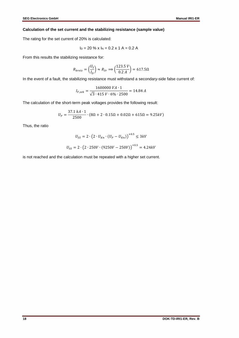
Calculation of the set current and the stabilizing resistance (sample value) The rating for the set current of 20% is calculated: ID = 20 % x IN = 0.2 x 1 A = 0.2 A From this results the stabilizing resistance for:
𝑅𝑘𝑟𝑒𝑖𝑠 = (𝑈𝑆
𝐼𝐷
) ≈ 𝑅𝑆𝑟 ⟹ (123.5 𝑉
0.2 𝐴) = 617.5Ω
In the event of a fault, the stabilizing resistance must withstand a secondary-side false current of:
𝐼𝐹,𝑠𝑒𝑘 =1600000 𝑉𝐴 ∙ 1
√3 ∙ 415 𝑉 ∙ 6% ∙ 2500= 14.84 𝐴
The calculation of the short-term peak voltages provides the following result:
𝑈𝑃 =37.1 𝑘𝐴 ∙ 1
2500∙ (8Ω + 2 ∙ 0.15Ω + 0.02Ω + 615Ω = 9.25𝑘𝑉)
Thus, the ratio
𝑈𝑆𝑆 = 2 ∙ (2 ∙ 𝑈𝐾𝑛 ∙ (𝑈𝑃 − 𝑈𝐾𝑛))+0.5
≤ 3𝑘𝑉
𝑈𝑆𝑆 = 2 ∙ (2 ∙ 250𝑉 ∙ (9250𝑉 − 250𝑉))+0.5
= 4.24𝑘𝑉
is not reached and the calculation must be repeated with a higher set current.

Manual IRI1-ER SEG Electronics GmbH
DOK-TD-IRI1-ER, Rev. B 19
Calculation of the set current and the stabilizing resistance (actual value) The rating for the set current of 40% is calculated again:
ID = 40 % x IN = 0.4 x 1 A = 0.4 A From this results the stabilizing resistance for:
𝑅𝑘𝑟𝑒𝑖𝑠 = (𝑈𝑆
𝐼𝐷
) ≈ 𝑅𝑆𝑟 ⟹ (123.75Ω
0.4𝐴) = 308.75Ω
Thus, the requirement of the short-term peak voltage is met.
𝑈𝑃 =37.1𝑘𝐴 ∙ 1
2500∙ (8 + 2 ∙ 0.15Ω + 0.02Ω + 308.75Ω)
𝑈𝑆𝑆 = 2 ∙ (2 ∙ 250𝑉 ∙ (4700𝑉 − 250𝑉))+0.5
= 2.98𝑘𝑉
Since the requirement is met, the set values and the resulting resistance values can be accepted. The calculation of the output requirement for the stabilizing resistance can be carried out analog to the calculation of sample 6.4.1.

SEG Electronics GmbH Manual IRI1-ER
20 DOK-TD-IRI1-ER, Rev. B
7. Housing The IRI1-ER can be supplied in an individual housing for flush-mounting or as a plug-in module for installation in a 19" mounting rack according to DIN 41494. Both versions have plug-in connec-tions. Relays of variant D are complete devices for flush mounting, whereas relays of variant A are used for 19“ rack mounting. Housing variant A to be installed in switchboards of protection class IP51. For switchboards of lower protection classes housing variant D can be used.
7.1 Individual housing The individual housing of the IRI1-ER is constructed for flush-mounting. The dimensions of the mounting frame correspond to the requirements of DIN 43700 (72 x 144 mm). The cut-out for mounting is 68 x 138 mm. The front of the IRI1-ER is covered with a transparent, sealable flap (IP54). For case dimensions and cut-out refer to "technical data". The individual housing is fixed with the supplied clasps from the rear of the switchboard panel.
7.2 Rack mounting The IRI1-ER is in general suitable for installation in a modular carrier according to DIN 41494. The installation dimensions are: 12 TE; 3 HE. According to requirements, the IRI1-ER-devices can be delivered mounted in 19" racks. If 19" racks are used the panel requires protection class IP51. For switchboards with lower degree of protection must be used individual housing.
7.3 Terminal connections The plug-in module has very compact base with plug connectors and screwed-type connectors.
max. 15 poles screw-type terminals for voltage and current circuits (terminal connectors series A and B with a short time current capability of 500 A / 1 s).
27 poles tab terminals for relay outputs, supply voltage etc.(terminal connectors series C, D and E, max. 6 A current carrying capacity). Connection with tabs 6.3 x 0.8 mm for cable up to max. 1.5 mm2 or with tabs 2.8 x 0.8 mm for cable up to max. 1 mm2. By using 2.8 x 0.8 mm tabs a bridge connection between different poles is possible.

Manual IRI1-ER SEG Electronics GmbH
DOK-TD-IRI1-ER, Rev. B 21
The current terminals are equipped with self-closing short-circuit contacts. Thus, the IRI1-ER-module can be unplugged even with current flowing, without endangering the current transformers connected. The following figure shows the terminal block of IRI1-ER:
Figure 7.1: Terminal block of IRI1-ER

SEG Electronics GmbH Manual IRI1-ER
22 DOK-TD-IRI1-ER, Rev. B
8. Relay testing and commissioning The following instructions should help to test the protection relay performance before or during commissioning of the protection system. To avoid a relay damage and to ensure a correct relay operation, be sure that:
the auxiliary power supply rating corresponds to the auxiliary voltage on site
the rated current and rated voltage of the relay correspond to the plant data on site
the current transformer circuits are connected to the relay correctly
all signal circuits and output relay circuits are connected correctly
8.1 Power On NOTE! Prior to switch on the auxiliary power supply, be sure that the auxiliary supply voltage corresponds to the rated data on the type plate. Switch on the auxiliary power supply to the relay (terminal C9/E9) and check that the LED „ON“ on the front plate lights up green.
8.2 Checking the set values Check the DIP-switch positions, in order to verify the parameterized set value. If necessary, the set value can be corrected by means of the DIP-switch.
8.3 Secondary injection test
8.3.1 Test equipment
ammeter of class 1 or better
auxiliary power supply with a voltage corresponding to the rated data on the type plate
single-phase AC-power supply (adjustable from 0 - 2.0 x IN)
test leads and tools
potentiometer
switching device
timer

Manual IRI1-ER SEG Electronics GmbH
DOK-TD-IRI1-ER, Rev. B 23
8.3.2 Example of a test circuit for a IRI1-3ER-relay For testing the IRI1-3ER-relay, only power signals are required. Figure 8.3.1 shows an example of a test circuit with adjustable power supply. The phases are tested individually one after the other.
Figure 8.1: Test circuit IRI1-3ER
8.3.3 Checking the pick-up and tripping values (IRI1-ER) With the IRI1-ER, the analog input signal of the single-phase testing AC must be supplied to the re-lay via the terminals B1/B2 for checking the pick-up value ID. For testing the differential current pick-up value, first the testing AC must be set below the set pick-up value Id. Then the testing AC is increased gradually, until the relay is trips. This is indicated by the LED ID lighting up red, with the relay tripping at the same time. Check that the value shown at the ammeter does not deviate by more than +/- 3% from the set pick-up value ID . The resetting value of the differential current pick-up value is determined, by slowly decreasing the testing AC, until the output relay ID is trips. The LED ID extinguishes (supposed the respective cod-ing was effected). Check that the resetting value is greater than 0.97 times the pick-up value, i.e. the resetting ratio of the differential current supervision is below 1.

SEG Electronics GmbH Manual IRI1-ER
24 DOK-TD-IRI1-ER, Rev. B
8.3.4 Checking the operating and resetting values (IRI1-3ER) With the IRI1-3ER, all analog input signals of the single-phase testing AC must be supplied to the relay via the terminals B1/B2; B3/B4; B5/B6 one after another for checking the pick-up value ID. For testing the differential current pick-up value, first the testing AC must be set below the set pick-up value Id. Then the testing AC is increased gradually, until the relay is trips. This is indicated by the LED ID lighting up red, with the relay tripping at the same time. Check that the value shown at the ammeter does not deviate by more than ±3% from the set pick-up value ID. The resetting value of the differential current pick-up value is determined, by slowly decreasing the testing AC, until the output relay ID is tripping. The LED ID extinguishes (supposed the respective coding was effected). Check that the resetting value is not lower than 0.97 times the pick up value, i.e. the resetting ratio of the differential current supervision is below 1. Note: An external timer must be used for checking the tripping time (individual time of the relay).
8.4 Primary injection test Principally, a primary injection test (real-time test) of a c.t. can be carried out in the same way as a secondary injection test. Since the cost and potential hazards may be very high for such tests, they should only be carried out in exceptional cases, if absolutely necessary.
8.5 Maintenance Maintenance testing is generally done on site at regular intervals. These intervals may vary among users depending on many factors: e.g. type of protective relays employed; type of application; op-erating safety of the equipment to be protected; the user’s past experience with the relay etc. For static relays such as the IRI1-ER/-3ER, maintenance testing once per year is sufficient, as ex-perience has shown.
Manual IRI1-ER SEG Electronics GmbH
DOK-TD-IRI1-ER, Rev. B 25
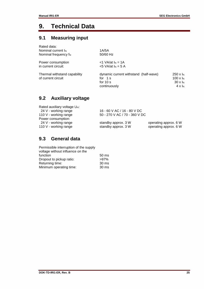
9. Technical Data
9.1 Measuring input Rated data: Nominal current IN 1A/5A Nominal frequency fN 50/60 Hz Power consumption <1 VA/at IN = 1A in current circuit: <5 VA/at IN = 5 A Thermal withstand capability dynamic current withstand (half-wave) 250 x IN of current circuit for 1 s 100 x IN for 10 s 30 x IN continuously 4 x IN
9.2 Auxiliary voltage Rated auxiliary voltage UH: 24 V - working range 16 - 60 V AC / 16 - 80 V DC 110 V - working range 50 - 270 V AC / 70 - 360 V DC Power consumption: 24 V - working range standby approx. 3 W operating approx. 6 W 110 V - working range standby approx. 3 W operating approx. 6 W
9.3 General data Permissible interruption of the supply voltage without influence on the function 50 ms Dropout to pickup ratio: >97% Returning time: 30 ms Minimum operating time: 30 ms

SEG Electronics GmbH Manual IRI1-ER
26 DOK-TD-IRI1-ER, Rev. B
9.4 Output relay The output relay has the following characteristics: Maximum breaking capacity: 250 V AC / 1500 VA / continuous current 6 A Breaking capacity for DC:
ohmsch L/R = 4 ms L/R = 7 ms
300 V DC 0.3 A / 90 W 0.2 A / 63 W 0.18 A / 54 W
250 V DC 0.4 A / 100 W 0.3 A / 70 W 0.15 A / 40 W
110 V DC 0.5 A / 55 W 0.4 A / 40 W 0.20 A / 22 W
60 V DC 0.7 A / 42 W 0.5 A / 30 W 0.30 A / 17 W
24 V DC 6.0 A / 144 W 4.2 A / 100 W 2.50 A / 60 W
Max. rated making current 64 A (acc. VDE 0435/0972 and IEC 65 / VDE 0860 / 8.86) Making current: minimum 20 A (16ms) Mechanical life span: 30 x 106 switching cycles Electrical life span: 2 x 10⁵ switching cycles at 220 V AC / 6 A Contact material: silver-cadmium-oxyde
9.5 System data Design standard: Generic standard: EN 50082-2, EN 50081-1 Product standard: EN 60255-6, IEC 255-4, BS 142 Specified ambient service Storage temperature range: - 40°C to + 85°C Operating temperature range: - 20°C to + 70°C Environmental protection class F as per DIN 40040 and per DIN IEC 68 2-3: relative humidity 95 % at 40°C for 56 days Insulation test voltage, inputs and outputs between themselves and to the relay frame as per EN 60255-6 and IEC 255-5: 2.5 kV (eff.), 50 Hz; 1 min Impulse test voltage, inputs and outputs between themselves and to the relay frame as per EN 60255-6 and IEC 255-5: 5 kV; 1.2 / 50 µs; 0.5 J High frequency interference test voltage, inputs and outputs between themselves and to the relay frame as per EN 60255-6 and IEC 255-22-1: 2.5 kV / 1MHz Electrostatic discharge (ESD) test as per EN 61000-4-2 and IEC 255-22-1: 8 kV air discharge, 6 kV contact discharge Electrical fast transient (Burst) test as per EN 61000-4-8 and IEC 801-4: 4 kV / 2.5 kHz, 15 ms

Manual IRI1-ER SEG Electronics GmbH
DOK-TD-IRI1-ER, Rev. B 27
Power frequency magnetic field test as per ENV 50141: electric field strength 10 V/m Surge immunity EN 61000-4-5: 4 kV Radio interference suppression test as per EN 55011: limit value class B Radio interference radiation test as per EN 55011: limit value class B Mechanical tests: Shock: class 1 acc. to DIN IEC 255-21-2 Vibration: class 1 acc. to DIN IEC 255-21-1 Degree of protection - front of relay: IP 54 by enclosure of the relay case and front panel (relay version D) Weight: approx. 1.5 kg Degree of pollution: 2 by using housing type A 3 by using housing type D Overvoltage class: III Influence variable values: Frequency influence: 40 Hz < f < 70 Hz: <3 % of set value Temperature influence: -20°C to +70°C Auxiliary voltage influence: no influence within the admissible range

SEG Electronics GmbH Manual IRI1-ER
28 DOK-TD-IRI1-ER, Rev. B
9.6 Setting ranges and steps
Relay type Parameter Setting range Steps Tolerances
IRI1-ER ID 5 % ... 82.5 % x IN 2.5 % ±3 % of set value
IRI1-3ER ID 5 % ... 82.5 % x IN 2.5 % ±3 % of set value
9.7 Dimensional drawing
Please note: A distance of 50 mm is necessary when the units are mounted one below the other in order to al-low easy opening of the front cover of the housing. The front cover opens downwards.

Manual IRI1-ER SEG Electronics GmbH
DOK-TD-IRI1-ER, Rev. B 29
10. Order form
Earth fault relay IRI1
Highly stabilized measuring 3-phase measuring, highly stabilized
ER
3ER
Rated current 1 A 5 A
1 5
Auxiliary voltage 24 V (16 to 60 V AC/16 to 80 V DC) 110 V (50 to 270 V AC/70 to 360 V DC)
L H
Housing (12TE) 19“-rack Flush mounting
A D
Technical data subject to change without notice!

SEG Electronics GmbH Manual IRI1-ER
30 DOK-TD-IRI1-ER, Rev. B
Setting list IRI1-ER Note! All settings must be checked at site and should the occasion arise, adjusted to the object / item to be protected. Project: Job.-no.: Function group: = Location: + Relay code: - Relay functions: Date: Setting of parameters
Parameter Unit Default settings Actual settings
ID Differential current % In 5
Setting of code jumpers
Code jumper
J1 J2 J3 J4
Default setting
Actual setting
Default setting
Actual setting
Default setting
Actual setting
Default setting
Actual setting
Plugged X X
Not plugged
not used not used