manual_jet2.pdf
TRANSCRIPT

Group 1 Table of contents Page 1
Release 3.00 Leibinger-Jet 2 se+
1.1 Table of contents
1.1 Table of contents........................................................................................1
1.2 Group directory...........................................................................................8
1.3 Menu level index.........................................................................................9
1.4 Publisher.................................................................................................. 11
1.5 Introduction.............................................................................................. 13
1.6 Document information ............................................................................... 14
2. Safety .......................................................................................................... 15
2.1 Scope of risks .......................................................................................... 15
2.2 Safety instructions and recommendations .................................................... 15
2.3 Intended use ............................................................................................ 18
2.4 Sources of danger ..................................................................................... 18
2.5 Safety sticker ........................................................................................... 22
2.6 Operating staff ......................................................................................... 23
2.7 Dangers due to electric energy.................................................................... 23
2.8 Personal protective equipment .................................................................... 23
2.9 Protective devices ..................................................................................... 23
2.10 Safety measures at the place of installation ................................................ 24
2.11 Dangers through consumables .................................................................. 24
3. Accident prevention ....................................................................................... 26
3.1 Storage and handling (normal use)............................................................... 26
3.2 First aid measures ..................................................................................... 27
3.3 Fire fighting measures................................................................................ 27
3.4 Measures in the event of accidental release (spillage)..................................... 28
4. Technical data ............................................................................................... 29
4.1 Dimensions, weights, connections............................................................... 29
4.2 Ambient conditions ................................................................................... 29
4.3 System interfaces ..................................................................................... 29
4.4 Power parameters ..................................................................................... 30
4.5 Font forms ............................................................................................... 30
4.6 Forms of printing ...................................................................................... 31
4.7 Font combinations..................................................................................... 31
4.8 Manner of working.................................................................................... 31
4.9 Software.................................................................................................. 32
5. Transport/Start up.......................................................................................... 33

Group 1 Table of contents Page 2
Release 3.00 Leibinger-Jet 2 se+
5.1 Transport, storage, shipping ....................................................................... 33
5.2 Mounting ................................................................................................. 33
5.3 Installation ............................................................................................... 34
5.3.1 Mains connection ..............................................................................34
5.3.2 Data interface X2 ..............................................................................35
5.3.2.1 Transmission protocol for operating system LJOS............................35
5.3.2.2 Pin assignment plan .....................................................................36
5.3.3 Print Go interface X5 .........................................................................37
5.3.4 Shaft encoder ...................................................................................37
5.3.4.1 Description and pin assignment .....................................................37
5.3.4.2 Mechanic installation ...................................................................38
5.3.5 Print head.........................................................................................39
5.4 Start up ................................................................................................... 40
5.4.1 Initial start up in an empty condition ....................................................40
5.4.2 Initial start up in a full condition ..........................................................42
6. Operation...................................................................................................... 44
6.1 Construction/Structure............................................................................... 44
6.2 Functional principle ................................................................................... 45
6.2.1 Method of working ............................................................................45
6.2.2 Drop creation ....................................................................................45
6.2.3 Drop charging ...................................................................................45
6.2.4 Drop deflection .................................................................................46
6.2.5 Creation of a character.......................................................................46
6.2.6 Summary of the individual procedures ..................................................47
6.3 Operating procedures and operating elements ............................................... 48
6.3.1 LCD touch display .............................................................................48
6.3.1.1 Switching on/switching off procedure ............................................48
6.3.1.2 Interval operation ........................................................................50
6.3.1.3 Status line in normal operation ......................................................51
6.3.1.4 Status line in error condition .........................................................51
6.3.1.5 Software Reset ...........................................................................52
6.3.2 Ink switch ........................................................................................53
6.3.3 Hardware Reset.................................................................................53
6.3.4 Potentiometer – Display illumination.....................................................54
6.3.5 Menu structure .................................................................................55

Group 1 Table of contents Page 3
Release 3.00 Leibinger-Jet 2 se+
6.4 Interfaces................................................................................................. 58
6.4.1 Data interface ...................................................................................58
6.4.2 PrintGO interface...............................................................................58
6.4.3 Shaft encoder interface ......................................................................58
6.4.4 Optional outputs................................................................................59
6.4.5 Optional inputs..................................................................................59
6.5 Description of the device ........................................................................... 60
6.5.1 Electronics cabinet with LCD touch display ...........................................60
6.5.2 Controller board ................................................................................61
6.5.3 DC power supply...............................................................................63
6.5.4 Hydraulics part..................................................................................64
6.5.4.1 Main pump .................................................................................66
6.5.4.2 Suction pump .............................................................................66
6.5.4.3 Viscosity control .........................................................................67
6.5.4.4 Leak detection ............................................................................68
6.5.5 Print head.........................................................................................68
6.5.5.1 Drop production unit with oscillator ...............................................70
6.5.5.2 Deflector unit..............................................................................70
6.5.5.3 Nozzle plate ................................................................................71
6.5.5.4 Nozzle seal with gutter.................................................................71
7. Data entry/programming ................................................................................. 72
7.1 General.................................................................................................... 72
7.2 Text administration ................................................................................... 72
7.2.1 Text entry ........................................................................................73
7.2.1.1 Bold print ...................................................................................74
7.2.2 Font parameters ................................................................................76
7.2.3 Text editor........................................................................................79
7.2.4 Graphics entry/graphics selection.........................................................79
7.2.5 Graphics editor..................................................................................80
7.2.6 Shift code input ................................................................................81
7.2.7 Barcode input....................................................................................83
7.2.7.1 Barcode information.....................................................................83
7.2.7.2 Barcode selection ........................................................................85
7.2.7.3 Barcode parameter.......................................................................86
7.3 Job administration..................................................................................... 87

Group 1 Table of contents Page 4
Release 3.00 Leibinger-Jet 2 se+
7.3.1 Opening job ......................................................................................87
7.3.2 Factory setting & default jobs .............................................................88
7.3.3 Deleting jobs.....................................................................................89
7.3.4 Storing and listing jobs.......................................................................90
7.4 User-/ Password administration................................................................... 91
7.4.1 Password levels (User groups) and user rights .......................................91
7.4.2 Call up password administration ..........................................................92
7.4.3 Activate user administration (first password input).................................92
7.4.4 User change and password change ......................................................93
7.4.4.1 Login as supervisor or advanced operator .......................................94
7.4.4.2 Change passwords ......................................................................94
7.4.4.3 Logoff as supervisor or advanced operator......................................96
7.4.5 Password forgotten ...........................................................................97
7.4.6 Deactivate user-/password administration .............................................97
7.5 Print start parameters ................................................................................ 99
7.5.1 Print delay and print repetition.............................................................99
7.5.2 Printgo distance .............................................................................. 100
7.5.3 Droplet flight time............................................................................ 100
7.5.4 Print Go and Print Go Gate................................................................ 101
7.5.5 Meter go function............................................................................ 102
7.5.6 Pre-defined print stop....................................................................... 104
7.6 Function parameters................................................................................ 105
7.6.1 Expiration time and shift times .......................................................... 105
7.6.2 Replacements and text sources ......................................................... 106
7.6.2.1 Printing with the function “ex. text” ............................................ 106
7.6.3 Reset counters ................................................................................ 108
7.6.4 Counter settings.............................................................................. 109
7.6.5 Counter programming ...................................................................... 110
7.6.6 Mode normal and reflected ............................................................... 112
7.7 Service/test/system parameters ................................................................ 113
7.7.1 Direct start and time/date ................................................................. 113
7.7.2 Monitoring functions (Control functions) ............................................. 114
7.7.2.1 Printgo- and strokego monitoring ................................................. 114
7.7.3 Encoder.......................................................................................... 115
7.7.4 Encoder parameters ......................................................................... 115

Group 1 Table of contents Page 5
Release 3.00 Leibinger-Jet 2 se+
7.7.5 Job change..................................................................................... 116
7.7.5.1 Printing with the function “external job selection”.......................... 116
7.7.6 Service/test- and diagnosis functions ................................................. 118
7.7.6.1 Summary graph (oscillator voltage curve)...................................... 118
7.7.6.2 Motor test ................................................................................ 119
7.7.6.3 Charging voltage test/Piezo test .................................................. 120
7.7.6.4 Software information ................................................................. 121
7.7.6.5 Permanent bleeding ................................................................... 121
7.7.6.6 Hydraulic test & parameters........................................................ 122
7.7.6.7 Touch screen calibration............................................................. 125
7.7.6.8 Service interval ......................................................................... 126
8. Trouble shooting .......................................................................................... 127
8.1 General.................................................................................................. 127
8.2 Error notification ..................................................................................... 127
8.3 Error messages ....................................................................................... 128
8.4 Other causes of errors ............................................................................. 132
9. Equipping/maintenance ................................................................................. 133
9.1 Equipping/operation................................................................................. 133
9.1.1 Refilling of ink and solvent................................................................ 133
9.1.1.1 General information ................................................................... 133
9.1.1.2 TAG reader and TAG identifier .................................................... 135
9.1.1.3 TAG reading, TAG information, TAG activating and filling the device135
9.1.1.4 Consumable medium with elapsed use-by date .............................. 137
9.1.1.5 TAG Error messages .................................................................. 139
9.1.1.6 Other TAG messages and Repair TAG .......................................... 139
9.1.2 Refill messages ............................................................................... 141
9.1.2.1 Messages in the standard operation ............................................. 141
9.1.2.2 Messages in the “host operation” ................................................ 142
9.2 Guarantee .............................................................................................. 144
9.3 Service/maintenance ............................................................................... 144
9.3.1 Daily servicing work......................................................................... 144
9.3.2 Weekly servicing work ..................................................................... 144
9.3.2.1 Lubrication ............................................................................... 144
9.3.2.2 Nozzle sealing ........................................................................... 145
9.3.3 Annual servicing work...................................................................... 147

Group 1 Table of contents Page 6
Release 3.00 Leibinger-Jet 2 se+
9.3.3.1 Filter replacement and ink change................................................ 148
9.3.4 Other servicing work........................................................................ 151
9.3.4.1 Adjusting the ink jet in the gutter................................................. 151
9.3.4.2 Replacement of the main pump ................................................... 152
9.3.4.3 Replacement of the battery and fuse............................................ 154
9.3.5 Servicing work with more difficult operating conditions ........................ 155
9.4 Cleaning ................................................................................................ 156
9.4.1 Daily cleaning work ......................................................................... 156
9.4.1.1 Cleaning the print head .............................................................. 156
9.4.1.2 Cleaning the deflector unit and gutter........................................... 157
9.4.2 Weekly cleaning work ...................................................................... 158
9.4.2.1 Cleaning of the spindle and guides of the nozzle seal...................... 158
9.4.3 Other cleaning work......................................................................... 159
9.4.3.1 Cleaning the nozzle.................................................................... 159
9.4.3.2 Cleaning the suction pump.......................................................... 161
9.5 Further maintenance measures (Service intervals)........................................ 163
9.6 Taking out of operation............................................................................ 164
9.7 Dismantling/disposal................................................................................ 164
10. Replacement parts...................................................................................... 165
10.1 Replacement parts electronics................................................................. 165
10.2 Replacement parts hydraulics.................................................................. 165
10.3 Replacement parts print head SK2........................................................... 166
10.4 Special tools......................................................................................... 166
10.5 Cleaning/servicing accessories ................................................................ 167
10.6 Periphery ............................................................................................. 167
10.7 Data entry devices ................................................................................ 168
11. Consumables............................................................................................. 169
12. Appendix .................................................................................................. 170
12.1 Hydraulics diagram................................................................................ 170
12.2 Interface layout plan.............................................................................. 171
12.3 Calculation of the print speed ................................................................. 173
12.4 Fonts................................................................................................... 176
12.5 List of graphics ..................................................................................... 178
12.6 Technical drawings................................................................................ 179
List of keywords/Index ..................................................................................... 182

Group 1 Table of contents Page 7
Release 3.00 Leibinger-Jet 2 se+
List of illustrations ........................................................................................... 189

Group 1 Group directory Page 8
Release 3.00 Leibinger-Jet 2 se+
1.2 Group directory The group directory serves as a guide through the device manual at hand to be able to find specific subject areas quickly.
Group Directory Page
1 Overview ....................................................................................1
Table of contents.........................................................................1
Group directory ...........................................................................8
Menu level index..........................................................................9
Publisher................................................................................... 11
Introduction .............................................................................. 13
2 Safety ...................................................................................... 15
3 Accident prevention ................................................................... 26
4 Technical data ........................................................................... 29
5 Transport/start up ...................................................................... 33
6 Operation.................................................................................. 44
Construction/Structure ............................................................... 44
Functional principle .................................................................... 45
Operating procedures/-elements................................................... 48
Interfaces ................................................................................. 58
Description of the device ............................................................ 60
7 Data Entry................................................................................. 72
8 Troble shooting/malfunctions..................................................... 127
9 Equipping/maintenance ............................................................. 133
10 Replacement parts.................................................................... 165
11 Consumables ........................................................................... 169
12 Appendix ................................................................................ 170
Hydraulics diagram................................................................... 170
Interface layout plan................................................................. 171
Calculation of the print speed .................................................... 173
Fonts ..................................................................................... 176
List of graphics........................................................................ 178
Technical drawings .................................................................. 179
Index...................................................................................... 182
List of illustrations.................................................................... 189

Group 1 Menu level index Page 9
Release 3.00 Leibinger-Jet 2 se+
1.3 Menu level index The menu level index guides you through the manual on hand in order to facilitate the search for the required information about the individual menu functions. Group Chapter Menu level no. Page
7 7.1 Menu level 1....................................................... 72
7 7.2 Menu level 2....................................................... 72
7 7.2.1 Menu level 3, 9, 15, 18 ....................................... 73
7 7.2.1 Menu level 50, 51, 52, 60.................................... 74
7 7.2.2 Menu level 3, 11 ................................................. 76
7 7.2.2 Menu level 12..................................................... 77
7 7.2.4 Menu level 50 (graphics entry) .............................. 79
7 7.2.5 Menu level 3, 10, 19 ........................................... 80
7 7.2.7.2 Menu level 3, 9, 17 ............................................. 85
7 7.2.7.3 Menu level 3, 22 ................................................. 86
7 7.3.1 Menu level 5, 45 ................................................. 87
7 7.3.3 Menu level 5, 47, 49 ........................................... 89
7 7.3.4 Menu level 5, 46, 50 ........................................... 90
7 7.4 Menu level 2, 7................................................... 91
7 7.5.1 Menu level 2, 4................................................... 99
7 7.5.5 Menu level 4, 8, 1 (meter go function) ................. 102
7 7.5.6 Menu level 4, (pre-defined print stop)................... 104
7 7.6 Menu level 2, 6, 41, 44 ..................................... 105
7 7.6.2 Menu level 6, 13 ............................................... 106
7 7.6.4 Menu level 6, 42 (counter settings) ..................... 109
7 7.6.5 Menu level 60 (counter programming) .................. 110
7 7.7 Menu level 2..................................................... 113
7 7.7.2 Menu level 8, 31 ............................................... 114
7 7.7.3 Menu level 8, 14 ............................................... 115
7 7.7.6.1 Menu level 16, 25 ............................................. 118
7 7.7.6.2 Menu level 16, 37 ............................................. 119
7 7.7.6.3 Menu level 16, 38, 39 ....................................... 120
7 7.7.6.4 Menu level 16, 35 ............................................. 121
7 7.7.6.5 Menu level 16, 34 ............................................. 121
7 7.7.6.6 Menu level 16, 29 ............................................. 122

Group 1 Menu level index Page 10
Release 3.00 Leibinger-Jet 2 se+
7 7.7.6.6 Menu level 43, 70 ............................................. 123
7 7.7.6.7 Menu level 16, 59 ............................................ 125
7 7.7.6.8 Menu level 16, 64 ............................................ 126

Group 1 Publisher Page 11
Release 3.00 Leibinger-Jet 2 se+
1.4 Publisher For questions regarding the operation and running of the LEIBINGER-JET 2 as well as in service case please contact the listed dealer address.
Dealer address
Paul Leibinger GmbH & Co. KG Special factories for numbering machines
Daimlerstraße 14 D-78532 Tuttlingen
Federal Republic of Germany
Phone +49 74 61/92 86-0 Fax +49 74 61/92 86-1 99
E-mail: [email protected]
Service hotline phone +49 74 61/92 86-8 63 Service hotline fax 0 74 61/92 86-8 69
Service hotline e-mail: [email protected]
American Branch Office Paul Leibinger
Numbering Machine L.P. 221 Wilson Avenue
Norwalk, CT 06854 USA
Phone +1 203 853-0022
Fax +1 203 853-3355
email: [email protected]

Group 1 Publisher Page 12
Release 3.00 Leibinger-Jet 2 se+
We reserve all rights, in particular the right to translate, distribute and reproduce. No part of this manual must be reproduced or distributed and stored through the use of electronic data processing systems or made accessible to third parties in any form (redrawn, photocopied, microfilmed or through any other process) without the written consent of the publisher. We reserve the right to make alterations to the scope of delivery at any time in the form of technology, hardware, software as well as the corresponding materials (and manual extracts) as a result of innovative further development of our devices. Texts, illustrations and technical drawings have been compiled with the greatest of care. Nevertheless errors cannot be excluded. Consequently no guarantee can be assumed for the correctness of the content of this manual and no claims can be asserted against Paul Leibinger GmbH & Co. KG. We shall be grateful for information regarding possible printing errors as well as for suggestions for the further optimisation of the device manual. Authoritative for the scope of delivery is not the manual but rather the written order confirmation.

Group 1 Introduction Page 13
Release 3.00 Leibinger-Jet 2 se+
1.5 Introduction We are pleased that you have decided in favour of a LEIBINGER-JET 2 device and welcome you as one of our customers. You now own a LEIBINGER-JET 2 device that has been developed and constructed on the basis of many years of experience and using the latest Leibinger technology. This results in a high degree of quality and the renowned Leibinger reliability. This manual shows you the fundamental advantages of the Leibinger Jet system manufactured by us, such as for example the fully automatic working, low maintenance etc..
The manual must be read thoroughly prior to to first start up in order to ensure that no damage to the device and/or endangering of the operating personnel results from a defective electrical connection and/or from incorrect operation.
Please pay particular attention to the safety instructions of the groups Safety instructions and accident prevention when handling consumables (ink and solvent).
Our devices are subjected to a quality control in our plant prior to delivery. If despite this the device or parts of it should be damaged or their function disturbed please advise us of this as fast as possible. The guarantee conditions can be seen from the confirmation of order. The warranty presupposes that the device or the installation is operated correctly in accordance with the available guarantee manual and any possible additional manuals and descriptions prepared by us. It is only through the use of inks and solvents from Paul Leibinger GmbH & Co. KG that optimum operating characteristics can be achieved. Should other inks and solvents be used all guarantee claims will expire.
Product liability!
No alterations whatsoever must be carried out on the entire LEIBINGER-JET 2 device. No liability will be accepted for damage or dangers resulting from inadmissible alterations.
Caution – risk of explosion!
The device must not be operated in rooms where there is a risk of explosion!

Group 1 Introduction Page 14
Release 3.00 Leibinger-Jet 2 se+
1.6 Document information The instruction Release 3.00 of 17th February 2006 is valid for Leibinger-Jet 2 se+ machines from the software-version V30.1.00.00.

Group 2 Safety instructions Page 15
Release 3.00 Leibinger-Jet 2 se+
2. Safety
2.1 Scope of risks The high performance printer LEIBINGER- JET 2 has been built in accordance with state-of-the-art standards and recognized safety requirements and has been equipped with protective devices. Operational and safety checks of the installation were carried out before it left the factory. In case of improper handling or misuse, however, there are dangers for
! the health of the operating staff
! the LEIBINGER-JET 2 and other real assets of the plant operator
! the efficient operation of the high performance printer All persons entrusted with the putting into service, the operation, the maintenance and the overhauling of the high performance printer must
! have the necessary qualification and
! strictly comply with this operating manual. YOUR safety matters! 2.2 Safety instructions and recommendations This operating manual use the following SYMBOLS with DANGER WARNINGS:
Indicates impending electrical danger!
Failure to observe this instruction can lead to serious injuries or to death!
Indicates a dangerous situation through pressurised media!
Failure to observe this instruction can cause injuries!
Indicates a dangerous situation!
Failure to observe this instruction can lead to material damage or to injuries!

Group 2 Safety instructions Page 16
Release 3.00 Leibinger-Jet 2 se+
Indicates a dangerous situation!
Failure to observe this instruction can cause serious hand injuries!
Indicates a dangerous situation through flammable materials!
Failure to observe this instruction can lead to material damage, to serious burns or to death!
Indicates a dangerous situation through irritating materials!
Failure to observe this instruction can lead to poisoning and to irritation of the eyes, the skin as well as of the respiratory organs!
Indicates the necessity of personal protective clothing!
Sufficient protective equipment must be worn. Failure to observe this instruction can lead to injury!
Indicates the necessity of observing the device manual and other instructions!
Failure to observe this instruction can lead to material damage, the loss of guarantee and to injury!
Indicates service activities!
This work must only be carried out by trained personnel or by Leibinger service technicians!

Group 2 Safety instructions Page 17
Release 3.00 Leibinger-Jet 2 se+
Indicates important user information
for safe and effective working.
Indicates recommendations for use
and other useful pieces of information.

Group 2 Safety instructions Page 18
Release 3.00 Leibinger-Jet 2 se+
2.3 Intended use The high performance printer LEIBINGER-JET 2 serves exclusively the contact-free marking, inscribing and coding of surfaces using the continuous ink jet process. The high performance printer can be used on the most varying materials (e.g. metal, synthetic material, glass, paper, wood, pressed materials, rubber etc.) with both, smooth as well as uneven, rough and stepped surfaces.
The intended use of this device also includes the observance of all instructions in this manual. Using the installation for other purposes is considered contrary to its intended use! For safety reasons conversions and alterations are only admissible following consultation with the manufacturer. Repairs to the device must only be carried out with original replacement parts. The manufacturer shall not be liable for damage resulting from use for other than the intended purpose or misuse.
2.4 Sources of danger Protective devices must neither be removed nor put out of operation.
Defects discovered must be rectified immediately.
Mains connection!
The device has no mains switch and must only be connected to a plug socket in the direct vicinity of the place of setting up!
Installation of the device
The device must be installed in a well ventilated room only and must be kept away from any source of heat, flame or sparks, e.g. radiant heater, etc.
Installation of the print head
The operating staff must not be exposed to danger due to the installation of the device in a production plant. Moving products under the print head may cause risk of crushing/cutting. The instructions of the machines directive must be strictly adhered to

Group 2 Safety instructions Page 19
Release 3.00 Leibinger-Jet 2 se+
Caution – risk of explosion!
Risk of explosion in the event of incorrect replacement of the battery. Replace only with an identical battery or with an equal value battery type in accordance with the recommendations of the manufacturer! The instructions of the battery manufacturer must be observed when disposing of the battery!
Caution – risk of explosion!
The device must not be operated in rooms where there is a risk of explosion!
Attention – risk of injury!
Your fingers could get caught between the frictional wheel and the production line. Keep your hands outside the danger area.
Dangerous electrical voltage!
Contact causes serious damage through an electric shock! Disconnect the device from the mains supply prior to opening. Remove mains plug!
Dangerous electrical voltage!
Contact causes serious damage through an electric shock! The print head must close automatically. Work on the head must only be carried out in a closed state!
Dangerous electrical voltage!
Parts of the device are still under voltage after blowing the protecting device! Disconnect the device from the mains supply prior to opening. Remove mains plug!
Dangerous electrical voltage!
Measurement under voltage has carried out only by electrical experts!

Group 2 Safety instructions Page 20
Release 3.00 Leibinger-Jet 2 se+
Risk of crushing/piercing!
During the closing movement of the print head your fingers could get caught between deflector unit or nozzle plate and gutter or during the opening movement between housing and gutter. Keep your hands outside of the danger area!
Risk of crushing/piercing!
During the closing movement of the print head your fingers could get caught between deflector unit or nozzle plate and gutter or during the opening movement between housing and gutter. Only carry out cleaning and service work with the machine placed idle. Remove mains plug!
The content is under pressure even if the device has been disconnected from the mains supply!
Ink under pressure can spray out. Prior to opening disconnect the device from the mains supply and let off the pressure!
Risk of fire!
Combustible gases and liquids cause serious burns. Sources of ignition must be kept away from the print head!
Dangerous material in the machine!
Danger of serious damage through burns, skin irriation and poisoning!
Warning!
Read and understand the device manual before using this machine. Incorrect operation can lead to injury or damage to the device!

Group 2 Safety instructions Page 21
Release 3.00 Leibinger-Jet 2 se+
Dangerous material in the machine!
Read the safety leaflets and the regulations on personal safety equipment!
Risk of injury!
Spraying of ink into the eyes can cause blindness. Prior to the opening of the device eye protection must be put on!
Risk of injury!
Ink escapes from the head aperture. Spraying of ink into the eyes can cause blindness. Eye protection is necessary!
Risk of injury!
Upon contact the contents causes skin irritation. Protective equipment is necessary!

Group 2 Safety instructions Page 22
Release 3.00 Leibinger-Jet 2 se+
2.5 Safety sticker Figure 1

Group 2 Safety instructions Page 23
Release 3.00 Leibinger-Jet 2 se+
2.6 Operating staff Only trained personnel must operate the device. The personnel must have appropriate training to enable them to be able to operate the LEIBINGER-JET 2 high performance printer professionally. Within the working area of the LEIBINGER-JET 2 device the operator is responsible with regard to third parties. The operator must
! put this operating manual at the operating staff’s disposal and
! make sure that they have read and understood them. 2.7 Dangers due to electric energy
The electrical and electronic components of the high performance printer are under voltage. The device must only be opened by trained personnel or by Leibinger service technicians. Prior to the opening of the device the device must be switched off and the mains plug removed. Further information on this subject can be found in the groups Trouble shooting and Equipping/maintenance.
2.8 Personal protective equipment Materials are processed in this device that cause irritations and which are under pressure. In order to avoid injury and damage the personnel must wear the following personal protective equipment during certain work procedures:
! suitable work clothing
! suitable eye protection
! suitable hand protection More detailed information can be found in the corresponding chapters of this manual as well as possibly in information and data leaflets of consumables. 2.9 Protective devices In an emergency the device is placed idle by removal of the mains plug.

Group 2 Safety instructions Page 24
Release 3.00 Leibinger-Jet 2 se+
2.10 Safety measures at the place of installation
Mains connection!
The device has no mains switch and must only be connected to a plug socket in the direct vicinity of the place of setting up!
Caution – risk of explosion!
The device must not be operated in rooms where there is a risk of explosion!
Installation of the device
The device must be installed in a well ventilated room only and must be kept away from any source of heat, flame or sparks, e.g. radiant heater, etc.
A place of setting up must be selected with sufficient load bearing capacity and stability. When setting up it must be observed that sufficient movement space is available for the operating and service personnel. Solvents are processed in the device, sufficient room ventilation must be ensured! Prior to assembly the place of setting up must be cleaned of dirt and contamination (residue of lubricants etc.). The working place surroundings should be kept clean at all times in order to ensure unrestricted access to the LEIBINGER-JET 2 device.
2.11 Dangers through consumables Inks are coloured liquids on a water or solvent basis. The safety instructions on the containers of the consumables as well as the instructions in the group Accident prevention must be especially adhered to in order to exclude dangers for persons and the surroundings. Further instructions can be found in the Safety Data Sheets. When handling consumables (inks/solvents) the danger instructions
and safety advice on the containers (transport, storage, distribution and correct disposal) must be observed!

Group 2 Safety instructions Page 25
Release 3.00 Leibinger-Jet 2 se+
In addition we recommend observance of the DIN safety information
leaflets 52900 of the inks and solvents used. Upon written request we shall be pleased to send you a copy. Please indicate the Leibinger article no. in all cases.
In the following you will find examples for the marking of inks and solvents. Figure 2 Examples: Labels for the marking of inks and solvents.

Group 3 Accident prevention Page 26
Release 3.00 Leibinger-Jet 2 se+
3. Accident prevention
The following presentation shows the measures in the event of an accident with ink and solvent with the danger marking
! slightly ignitable
! irritates the eyes and the respiratory organs. 3.1 Storage and handling (normal use) GENERAL These products must only used at points that are free from
open flames and other ignition sources. Do not use pressure for emptying – the container is not a pressure vessel. Good household practice and regular, safe removal of the waste materials restrict the danger of self-ignition and other risks of fire to a minimum. The product can charge statically. When pouring from one container to another use a mass lead. The workers must wear anti-static shoes and clothing and the floors must be conductive.
STORAGE Observe the marking information. Store at 5 to 25°C in a warm, well ventilated location at a safe distance from heat and ignition sources and direct sunlight. Do not smoke! Do not grant access to unauthorised persons. Open containers must be properly closed and stored upright in order to avoid leakage. Smoking, eating and drinking must be forbidden in the storage and working areas. Always keep in containers from the same material as the delivery containers.
HANDLING The development of combustible or explosive vapour concentrations must be prevented and vapour concentrations avoided that are above the threshold values of the employers liability insurance association. Keep containers closed tightly. Keep sources of heat and sparks as well as open flames well away. Use only spark-free tools. Electrical devices must be protected in accordance with the corresponding standard. Avoid contact with the skin and eyes. Do not inhale vapours and spray mist.

Group 3 Accident prevention Page 27
Release 3.00 Leibinger-Jet 2 se+
3.2 First aid measures EYES Contact lenses must be removed. Rinse thoroughly with pure,
fresh water for at least 10 minutes, keep eyelids spread and call a doctor.
SKIN Remove contaminated clothes. Wash skin thoroughly with soap and water or with a branded skin cleansing agent. DO NOT use solvents or thinners.
INHALING Take patient into the fresh air and keep warm and calm. In the event of irregular breathing or of breath being missed resuscitate artificially. Do not give anything orally, place unconscious patients on their side and call a doctor.
MISCELLANEOUS In case of doubt or with persistent symptoms call a doctor. Never give anything orally to unconscious patients.
3.3 Fire fighting measures EXTINGUISHING
AGENTS Recommended: Alcohol-resistant foam, spray water/mist, CO2
or powder
DO NOT use water jets. Cool closed containers exposed to the fire with spray water.
RISK OF FIRE AND EXPLOSION
As the product contains combustible organic constituents, a thick, black smoke develops in the event of fire that contains dangerous combustion products. Decomposition products can constitute a danger to health. Extinguishing waste water must not enter the waste water channels or waters.
PROTECTIVE MEASURES
If necessary suitable, independent breathing apparatus is required.

Group 3 Accident prevention Page 28
Release 3.00 Leibinger-Jet 2 se+
3.4 Measures in the event of accidental release (spillage) PRECAUTIONARY
MEASURES Switch off sources of ignition and ventilate room. Keep personnel that is not absolutely necessary away. Do not inhale any vapour. Observe the protective measures listed.
ENVIRONMENTAL PROTECTION MEASURES
DO NOT allow to enter waste water channels or waters. Should the product enter waste water channels or the drainage system the local water supply authority must be informed immediately. In the event of contamination of streams, rivers or lakes inform the national water authorities. Vapour is heavier than air and can spread out on the ground. In combination with air it can form an explosive mixture.
RESTORATION Restrict and suck up spilled substances with a non-combustible absorbent material (e.g. sand, earth, vermiculite, infusorial earth) and collect in a suitable container for removal. Preferably clean areas with spilled substances with a detergent. Avoid solvents.

Group 4 Technical data Page 29
Release 3.00 Leibinger-Jet 2 se+
4. Technical data
4.1 Dimensions, weights, connections Figure 3
Cabinet: High grade steel Width 440 mm, depth 280 mm,
height 480 mm Weight: 22 kg Print head: High grade steel housing Length 278 mm, width 42.5 mm,
height 42.5 mm Length of the print head lead 3 m,
available up to 12 m as an option
Weight: 1 kg
Print head installation position: Any installation position of the print head Print head securing: Screw thread M4 (2x) in the print head with interval
85 mm Electrical connection values: 115 - 230 V AC ,47-60 Hz Power consumption: Max. 50 VA, mains part reactive current
compensated Form of protection: IP 54 (higher form of protection possible on request) 4.2 Ambient conditions Temperature range: + 5° C to + 45° C
(no rapid change of temperature) Relative humidity: Max. 90 % relative humidity (non-condensating) 4.3 System interfaces Product sensor: 5-pole connection bush, 24 V, 100 mA, for optical,
inductive, capacitive proximity switch NPN/PNP types Pressure synchronisation: (optional)
Digital incremental shaft encoder with 12-pole bush on the rear side of the cabinet (5 V, EIA 422 A)

Group 4 Technical data Page 30
Release 3.00 Leibinger-Jet 2 se+
Potential free inputs: Optional 12 for special functions Outputs: NPN 24 V, 500 mA, e. g. for device status and error
notifications Data entry: Standard ASCII characters via V 24/RS 232 Data buffering in the event of voltage failure Transmission speed 38400 Baud 4.4 Power parameters Printing power
Character height: approx.
! min.: 0.8 mm
! max.: 12 mm,
depending on form of font, head distance, nozzle diameter, ink and product surface
(e.g. 40 prints/sec with 10 characters) Writing speed max. 2700 characters/s (at 96 kHz) Character density
e.g. 26 characters/80 mm at 140 m/min product speed (5x5 matrix)
(see calculation of the inscription speed in the group Appendix)
4.5 Font forms All type forms can be combined as desired in the
writing Printing of 1-4 lines or 24 dot matrix Double spaced type, rapid Micro type Chimney type 5x7 matrix Negative type Capitals and non-capitals, umlauts, special characters Matrix forms: 5x5, 7x5, 9x5, 9x7, 16x10, 11x8,
12x8, 14x10, 24x24, Bern 16 (16x11-matrix), Bern 24 (24x18-matrix) Barm 16 (16x12-matrix)
Graphics Graphics character record Graphics 1 to 24 dot Bold print Contrast type

Group 4 Technical data Page 31
Release 3.00 Leibinger-Jet 2 se+
Bar code 1 to 24 dot
Bar code 39 without plain type Bar code 39 with plain type Bar code 2 from 5 interleaved without plain type Bar code EAN 8 with plain type Bar code EAN 13 with plain type Bar code UPC A with plain type Bar code UPC E with plain type Code128 B Code128 C Postnet Data Matrix
Kanji 7x 8 / italics 7x5, Kanji 9x 9, Kanji 16x16, Kanji 24x24
Pers 9x 9, Pers 16x11 Double spaced rapid, 7x5
Double spaced: 1st line 7x5, 2nd line 16x10 Double spaced: 1st line 16x10, 2nd line 7x5 Double spaced rapid, 5x5 Double spaced: 1st line 9x5, 2nd line 5x5 Double spaced: 1st line 5x5, 2nd line 9x7
4.6 Forms of printing Double interval Texts backwards Symbols mirror inverted Symbols mirror inverted and upside down Symbols mirror inverted, upside down and text
backwards Reciprocally legible type matter, reverse Bold print, inverse 4.7 Font combinations All type forms can be shown in any form desired in
one type matter in the desired matrix. 4.8 Manner of working Fully automatic manner of working through: ! Automatic jet closure, the print head is ready for
writing immediately following starting up ! Automatic, electronic drop call-off regulation for
compensating changing ambient and operating temperatures.
! Automatic viscosity regulation ! Ability to refill ink and solvent during writing
operation

Group 4 Technical data Page 32
Release 3.00 Leibinger-Jet 2 se+
4.9 Software ! Selectable print delay or print repetition
! Any desired combination of constant and variable texts within a print line
! Continuous counter numbering with selectable increment or decrement, starting value, limit value
! Current date and time inscription, original date ! Freely programmable presentation of graphics,
Japanese or Chinese characters with a high resolution
! Job administration allows the storage and the calling up of texts and of all print relevant parameters
! Bar codes (e.g. bar code 39, EAN 8/13 and code 2/5 interleaved)
! Text organiser ! Counter marking ! Shift operation

Group 5 Transport/start up Page 33
Release 3.00 Leibinger-Jet 2 se+
5. Transport/Start up (Putting into service) 5.1 Transport, storage, shipping In order to avoid damage during transport the following instructions must be observed. The LEIBINGER-JET 2 must only be transported in a standing position. It is packed in a cardboard box with special polystyrene inserts for safe dispatch during delivery. Transport of the device must only be made in this packing in order to avoid damage. Note! Storage temperatures below +5°C and above +50°C as well as storage at outside are not admissible and can lead to damage! 5.2 Mounting
Caution – risk of explosion!
The device must not be operated in rooms where there is a risk of explosion!
Installation of the device
The device must be installed in a well ventilated room only and must be kept away from any source of heat, flame or sparks, e.g. radiant heater, etc.
Check device for damage! When determining a suitable place of setting up, the necessary additional space requirement for the movement room of the operating and service personnel must be taken into consideration. Solvents are processed in the device, adequate room ventilation must be ensured! Figure 4
Movable underframe for LEIBINGER-JET 2: 54-002 601 KA
For this it is expedient to place the device on a device support.
weldment seam

Group 5 Transport/start up Page 34
Release 3.00 Leibinger-Jet 2 se+
The device has four fastening possibilities for secure setting up and should be screw connected at the place of setting up. Figure 5
A place of setting up with sufficient load bearing capacity and stability
must be chosen. Prior to assembly the place of setting up must be cleaned of dirt and contamination (residue of lubricants etc.) .
5.3 Installation For the adaptation to a production line various work must be carried out prior to commissioning and operating parameters set. 5.3.1 Mains connection
Mains connection!
The device has no mains switch and must only be connected to a plug socket in the direct vicinity of the place of setting up!
The LEIBINGER- JET 2 must be connected to alternating current 115 - 230 V AC, 47 – 60 Hz with a corresponding plug. The plug socket should be equipped with a clear marking (e.g.: LEIBINGER-JET 2).
377 mm
120 m
m
M6 (4x)

Group 5 Transport/start up Page 35
Release 3.00 Leibinger-Jet 2 se+
5.3.2 Data interface X2 The operation of the LEIBINGER-JET 2 is normally done via the LCD touch display.
The RS 232 input on the rear side of the device (9-pole plug, female, interface X2) can be used as an external data interface for connection to a PC, notebook or host. The standard baud rate is 38400 Baud. For older software versions the baud rate can be reduced to 9600 baud with the help of a special bridge plug. Further more a special plug to increase the transmission rate to 115200 is obtainable on request. The interface enables the downloading/running of software, of jobs and of graphic symbols. A special connection cable and the Leibinger LJ-FLASH program is required to use this function. Further more this interface can be used via a PC for a comfortable programming of one or more Leibinger-Jet 2. For this you would need additionally the Leibinger-software Win Jet.
When using a personal computer with RS 232 C interface a
maximum connection cable length of 10 metres should not be exceeded, with greater transmission distances the use of an RS 422 connection is recommended.
5.3.2.1 Transmission protocol for operating system LJOS The programming device that is connected to the LEIBINGER-JET 2 must work with
the following transmission protocol: ! Asynchronous Mode ! 8 bit/character
! 1 stop bit ! Parity = no parity, no parity calculation
Figure 6

Group 5 Transport/start up Page 36
Release 3.00 Leibinger-Jet 2 se+
5.3.2.2 Pin assignment plan The RS 232 C / V24 interface has the following connections on the 9-pole SUB-D
plug: ! PIN 2 RXD receive Data ! PIN 3 TXD transmit Data ! PIN 5 GND ground, mass ! PIN 7 RTS ! PIN 8 CTS ! PIN 9 +5 VDC supply voltage for programming device (max. 0.5 A)
When entering the data the respective description must be observed. Leibinger
offers a correspondingly protected cable for the connection. Data connection cable PC to LEIBINGER- JET 2: 54-002 295 SA Figure 7
X2-Connection cable (54-002 295 SA)
Pin assignment of connection cable X2

Group 5 Transport/start up Page 37
Release 3.00 Leibinger-Jet 2 se+
5.3.3 Print Go interface X5 (print triggering) For the creation of the print triggering (print go signal) a 5-pole plug socket X5 is
assembled on the rear side of the device on which an external print go signal can be fed in. The signal can be created with a bounce free and potential free contact (inner resistance ≤ 1 kΩ) or with electronic PNP/NPN proximity switches (observe Pin assignment in the connection plug). A supply voltage of 24 V DC, 100 mA for sensors can also be taken from the plug socket (X5) on the rear side of the device.
The print go signal is created through a signal jump. A shaft encoder must be used
in addition for the synchronisation of the print speed with the product speed (with variable speed).
Figure 8
5.3.4 Shaft encoder 5.3.4.1 Description and pin assignment With a variable product speed a shaft encoder must be used for the synchronisation
of the print speed with the product speed or for the regulation of the constant type width. Shaft encoders with 5 volt logic and line drivers as per EIA 485 A or EIA 422 A can be used. The transmission ratio between product and shaft encoder speed should be selected in such a manner that a maximum output frequency of 150 kHz is not exceeded. Shaft encoders with 1000, 2500, 5000 and 10000 impulses/revolution are avaiable.
Example: Photo cell with connection cable and plug
Plug X5 for product sensor at thebackside of the electronics cabinet.

Group 5 Transport/start up Page 38
Release 3.00 Leibinger-Jet 2 se+
Leibinger ordering number: see group replacement parts
With more difficult operating conditions (dust or humidity) shaft encoders with IP 66 form of protection should be used.
Figure 9
Should alternative shaft encoders be used, the minimum impulse issued should be 3 impulses /mm in order to achieve a sufficient resolution!
5.3.4.2 Mechanic installation With mechanic installation of the shaft encoders in all cases
attention must be paid to ensuring that the encoder is protected from axial and radial burdening during assembly and in continuous operation. For this a folding bellows or synthetic material coupling is used.
If the circumstances allow the shaft encoder can also be adapted to a production line with a frictional wheel.
Attention – risk of injury!
Your fingers could get caught between the frictional wheel and the production line. Keep your hands outside the danger area.
Figure 10
Leibinger ordering number: see group replacement parts
Example: Shaft encoder with connection cable and plug
Pin Signal Colour A +5V BN 0,5mm²
B GND WH 0,5mm² C free D A BN 0,14mm²
E A GN 0,14mm²
F B GY 0,14mm²
G B PK 0,14mm²
H ZERO RD 0,14mm²
J ZERO BK 0,14mm²
K free
Pin assignment

Group 5 Transport/start up Page 39
Release 3.00 Leibinger-Jet 2 se+
5.3.5 Print head The print head must be assembled to the product to be inscribed in such a manner
that the opening in the head cover is vertical to the direction of movement of the product. It can be installed horizontally, vertically, from above or from below. In the event of installation from below the penetrating of dirt into the print head must however be prevented (head ventilation – option/article no.: 54-002 322 SA). The print head assembly unit should be designed in such a manner that rapid separation of the print head from the machine is possible for cleaning purposes. Two screw threads M4 x 7.00 deep are available for secure fastening!
Figure 11
The print head must be secured vibration free. The head umbilical of the print head must not go statically below a radius of R35 and dynamically below a radius of R90!
The distance of the print head to the product depends on the print height. The
lower the required print height the smaller the distance of the print head to the product must be (type quality better with lesser interval). Recommended is a distance of ≈ 8 mm!
Installation of the print head
The operating staff must not be exposed to danger due to the installation of the device in a production plant. Moving products under the print head may cause risk of crushing/cutting. The instructions of the machines directive must be strictly adhered to.
1 – Axis of the production line 2 – Print head 3 – Fastening screw thread 4 – Head umbilical
4
3

Group 5 Transport/start up Page 40
Release 3.00 Leibinger-Jet 2 se+
5.4 Start up (Putting into service) 5.4.1 Initial start up in an empty condition Dangerous electrical voltage!
Contact causes serious damage through an electric shock! Disconnect the device from themains supply prior to opening. Remove mains plug!
Risk of injury!
Spraying of ink into the eyes can cause blindness. Prior to the opening of the device eye protection must be put on!
This work must only be carried out by trained personnel or by Leibinger service technicians!
Check device for dirt! More detailed information on the components described
below can be found in the group Operation in the chapters Structure and description of the device.
Print head Remove the head cover. Check the deflector unit as well as the charging electrode
for dirt or transport dust and if necessary blow out with compressed air. Switch on ink switch (ink on – switch upwards).
Refilling unit The storage containers were emptied before dispatch so as to prevent the flowing
out of ink and solvent and as a result damage during transport. Consequently the device must be filled before the initial start up. Details of the filling process can be found in the group Equipping/maintenance in the chapter Refilling of ink and solvent!
Recreate mains connection and switch on the LEIBINGER-JET 2 with the LCD touch
display. Details on the switching on procedure can be found in the group Operation in the chapter Operating procedures and operating elements! Following switching on the device is bled automatically i.e. the ink is automatically pumped from the storage container into the pressure tank. This procedure can last up to 5 minutes.

Group 5 Transport/start up Page 41
Release 3.00 Leibinger-Jet 2 se+
The operating pressure must rise to the value set in the menu level <E43> (“Main
menu ! service/test/system parameter ! /service/test & diagnostics ! hydraulic test & parameter ! service menu“). The operating pressures are approx. 3 bar/70µm jet or approx. 4 bar/40 mm jet. The pressure achieved can be read in the menu level <E29>(“Main menu ! service/test/system parameter ! service/test & diagnostics ! hydraulic test & parameter“).
Should the operating pressure not be built up after approx. 30 seconds, if necessary
the function of the main pump and of the compressor must be checked! In the display the pressure is shown in mbar i.e. a display value of
3000 stands for 3 bar.
An error notification that may possibly be displayed “Ink tank is low level please
refill ink!” must be confirmed by tapping on the status field or ink refilled. The filling procedure has been concluded when no refill error appears. Place on the head cover of the print head and press the status field <nozzle closed>. The jet opens and the status display changes. If the notification “Print Yes” appears in the status field <print> the LEIBINGER-JET 2 is ready for operation. The data can now be entered as described in the group Operation in the chapter Operating procedures and operating elements as well as in the group Data entry.
[E29]
Display of the achievedpressure

Group 5 Transport/start up Page 42
Release 3.00 Leibinger-Jet 2 se+
5.4.2 Initial start up in a full condition Dangerous electrical voltage!
Contact causes serious damage through an electric shock! Disconnect the device from the mains supply prior to opening. Remove mains plug!
Risk of injury!
Spraying of ink into the eyes can cause blindness. Prior to the opening of the device eye protection must be put on!
This work must only be carried out by trained personnel or by Leibinger service technicians!
Check device for dirt! More detailed information on the components described
below can be found in the group Operation in the chapters Structure and description of the device.
Print head Remove the head cover. Check the deflector unit as well as the charging electrode
for dirt or transport dust and if necessary blow out with compressed air. Switch on ink switch (ink on – switch upwards).
Recreate mains connection and switch on the LEIBINGER-JET 2 with the LCD touch
display. Details on the switching on procedure can be found in the group Operation in the chapter Operating procedures and operating elements! Following switching on the device is bleed automatically i.e. the ink is automatically pumped from the storage container into the pressure tank. This procedure can last up to 5 minutes. The operating pressure must rise to the value set in the menu level <E43> (“Main menu ! service/test/ system parameter ! service/test & diagnostics ! hydraulic test & parameter ! service menu“). The operating pressures are approx. 3 bar/70µm jet or approx. 4 bar/40 mm jet. The pressure achieved can be read in the menu level <E29>(“Main menu ! service/test/ system parameter ! service/test & diagnostics ! hydraulic test & parameter“). Should the operating pressure not be built up after approx. 30 seconds, if necessary the function of the main pump and of the compressor must be checked!

Group 5 Transport/start up Page 43
Release 3.00 Leibinger-Jet 2 se+
In the display the pressure is shown in mbar i.e. a display value of
3000 stands for 3 bar.
Press the status field <nozzle closed>. The jet opens and the status display alters. A check must ensue as to whether the ink jet escapes or enters the gutter. Otherwise switch off ink by pressing the ink switch and clean jet as described in the chapter Cleaning of the jet. Place the head cover of the print head back on again. If the notification “Print Yes” appears in the status field <print> the LEIBINGER-JET 2 is ready for operation. The data can now be entered as described in the group Operation in the chapter Operating procedures and operating elements as well as in the group Data entry.
[E29]
Display of the achievedpressure

Group 6 Operation – Construction/Structure Page 44
Release 3.00 Leibinger-Jet 2 se+
6. Operation
6.1 Construction/Structure The LEIBINGER-JET 2 high performance printer is manufactured from a solid high grade steelcabinet. It consists of the following main components. Figure 12 1 – Electronics cabinet 2 – LCD touch display 3 – Hydraulics cabinet 4 – Refill unit 5 – Print head with head umbilical
The fundamental electronic components of the LEIBINGER- JET 2 such as the mains part, the LCD touch display and the controller board are accommodated in the electronics cabinet. The LCD touch display serves the display of the system conditions of the LEIBINGER-JET 2 and the operation of the device. All components that are necessary for the conveying and preparation of the ink are accommodated in the hydraulics cabinet. The refill unit serves the supply of the consumables. It contains two separate storage containers for ink and solvent. The print head contains all mechanical, electronical and hydraulic components that are necessary for the creation of an inscription. It is connected to the hydraulics cabinet via a flexible tube. Screw threads for secure fastening are integrated into the cabinet of the print head.

Group 6 Operation – functional principle Page 45
Release 3.00 Leibinger-Jet 2 se+
6.2 Functional principle 6.2.1 Method of working The Leibinger-Jet 2 works in accordance with the continuous ink jet process. In this
a constant ink jet is emitted from a jet nozzle which is broken down into a series of equal size drops under the influence of mechanical oscillations. If required these drops are individually charged up electrostatically and deflected into a constant electrical field depending on the charge. As a result not just one point but rather a line of points can be applied contact-free with one jet. If the product used is moved vertically to the drop deflection two-dimensional patterns (characters) can be created. The drops that are not required for a programmed inscription are not charged and flow uninfluenced through the electrical deflection field into a gutter. In the gutter the drops are sucked up by a suction pump and fed back into the ink tank. Depending on the application alphanumeric data can be entered with the LCD touch display.
Data for font and texts are stored in the device (even in the event of power failure). If required it can be called up, altered or deleted quickly and easily.
6.2.2 Drop creation During the drop creation the ink is pressed through a jet nozzle under pressure and
at the same time modulated in such a way by highly frequent sinus oscillations that are imposed on the drop that it attaches itself to the nodal points of the oscillations and breaks down into individual drops at a specific distance lA (please see the following figure “Creation of a character”) from the jet. The oscillations are created with an oscillatory system that is excited by a Piezo oscillator.
6.2.3 Drop charging In order to be able to charge the drops it is necessary for the ink to have electrical
conductivity. This is possible through the use of specific salts that dissociate in the solvent used. The drop brake-off point of the modulated jet is automatically set in such a manner that this happens inside the charging electrode.

Group 6 Operation – Functional principle Page 46
Release 3.00 Leibinger-Jet 2 se+
The drops can now be charged up by creation of voltage between jet and charging
electrode, because they are given a negative charge through the charge shift resulting in the charge electrode gap. A specific charge voltage is clearly allocated for each drop charge.
6.2.4 Drop deflection After the drops have left the charging electrode they fly through an electrical field.
Here, those droplets that were previously charged in the charging electrode are deflected. The drops that have not been charged fly straight ahead into the gutter. Here they are sucked up and fed back to the circular flow of ink. The charged drops are only deflected in one direction, the other direction is performed by the product to be inscribed.
6.2.5 Creation of a character Each character is defined by a two-dimensional matrix, e.g. 7 x 5. An ink drop can
be assigned to every point of intersection. The character is formed by deflecting the ink drops in a vertical direction and by moving the product which is to be imprinted horizontally. The ink drops which are not to be positioned are not given electrostatic charges in the charging electrode, and pass through the electrical field without being deflected and on into the gutter tube. The values needed for generating the charge voltages for each individual character are stored in memory devices (FPROMS) on the controller board.

Group 6 Operation – Functional principle Page 47
Release 3.00 Leibinger-Jet 2 se+
6.2.6 Summary of the individual procedures Figure 13
Creation of a character
Abriss-Punkt
X
X+1
Character height created by drop deflection
Drop brake-off point
Character „E“ build with a 7 x 5 matrix
Rel. movement direction ofthe description area
Gutter
Deflector plate
Charge electrode with deflectorelectrode
Nozzle (jet)
Oscillator
Cha
ract
er w
idth
cr
eate
d by
th
e re
l.m
ovem
ent
of t
he d
escr
iptio
n ar
ea

Group 6 Operation – procedures and elements Page 48
Release 3.00 Leibinger-Jet 2 se+
6.3 Operating procedures and operating elements 6.3.1 LCD touch display 6.3.1.1 Switching on/switching off procedure Figure 14
The LEIBINGER-JET 2 is switched on by touching any point of the touch display (1) that is still dark. Contact duration approx. 2 sec. The start screen with the software-version number (2) and the execution identification (3) are displayed for 3 sec.. Information about execution identification: 64 = Actual frequency 64 KHz 96 = Actual frequency 96 KHz n = for non-pigmented ink p = for pigmented ink The entire control is performed via the touching of the touch fields. The fields are activated by light touching with the finger or the touch pen (included in the scope of delivery) whereby the precision and not the pressure is decisive. Only fields with bold frames are active and operable. Thinly edged fields (buttons) are currently not operable. Now the device starts automatically with the bleeding of the system. The bleeding lasts between 1-5 minutes. During the procedure the notification “BLEED” flashes in the status line (4). The bleeding procedure is ended by pressing
the status line. Following ending or after cancelation of the bleeding the status display (3) of the device alters (see following figure).
2
3
4
[E0]

Group 6 Operation – procedures and elements Page 49
Release 3.00 Leibinger-Jet 2 se+
Figure 15
The touch field <request> (5) calls up the basis level <E1>. The device can be switched off with the touch field <off> (6).
Unintentional touching can trigger undesired device conditions.
After switching off approx. 5 seconds must pass before the device can be switched on again.
Figure 16
The following functions and displays are available in the basic level. The touch field <main menue>(7) opens the programming level <E2> for the selection of print jobs etc.. More detailed information on this subject can be found in the group Data entry. In the touch field <product counter> (8) the current values of the product counter are displayed. The counter can be reseted by pressing on this field (8). <Power off> (9) leads back to the level <E0>. Switching off of the device is only possible after carrying out of a print stop and with the nozzle closed.
With the touch field <printstart> (10) the print order is released for performance. It
is printed as soon as a Print Go is triggered. When a print procedure is running the display of the field changes to <printstop>. To be able to perform a print order a text must have been entered or an existing job selected. Further information on this subject can be found in the group Data entry in the chapters Text administration and job administration!
5
[E0]
6
4
7
12
[E1]
11
8
10
9

Group 6 Operation – procedures and elements Page 50
Release 3.00 Leibinger-Jet 2 se+
The display (11) shows the name of the active job. The text to be printed is shown
in the field (12). The display of the text shown is updated when printing is started (e.g. when printing counters).
6.3.1.2 Interval operation The device must be connected to the electricity mains.
The device switches itself on automatically independently of the ambient conditions!
In the switched off state the integrated interval function activates the LEIBINGER-
JET 2 automatically in accordance with the times set in the menu level <E43> (“Main menu ! service/test/ system parameter ! service/test & diagnostics ! hydraulic test & parameter ! service menu“). By means of the circulation of the ink it is ensured that in cases of extended idle periods no drying of the ink or depositing of ink constituents results. The viscosity of the ink remains constant. Further information about the entry of the interval times can be found in the chapter Hydraulic test and parameters!
[E43]

Group 6 Operation – procedures and elements Page 51
Release 3.00 Leibinger-Jet 2 se+
6.3.1.3 Status line in normal operation Figure 17
In normal operation the status line indicates notifications on device condition and processes, date and time. The active processes are shown de-posited (inversely). The following status fields are shown: Date/time <1> the upper line shows the time, the lower line the date.
Print <2> displays the readiness for printing (YES/NO).
Ink <3> displays the position of the ink switch (on/off). The ink switch is installed on the print head. Cover <4> signals whether the cover of the print head (open/closed) is closed or open. Nozzle <5> indicates the current operating status of the noozle (open/opens/ closes/closed). The field also functions as a touch field for opening and closing the nozzle (jet).
6.3.1.4 Status line in error condition The error notifications are shown flashing in the status line of the LCD touch
display. The error notification texts contain the error denomination, the possible cause of the error or the possible error removal measures. The error is acknowledged by touching the touch field <Error notification> (status line).
Figure 18
Status line with error notifications (specimen illustration)
2 1
3
4
5
[E1]
[E1]

Group 6 Operation – procedures and elements Page 52
Release 3.00 Leibinger-Jet 2 se+
6.3.1.5 Software Reset Hidden reset button (defined position on the touch screen): With this hidden reset button a factory setting can be carried out when switching
on the device. The device is started with the standard settings and a default job, i.e. type height/width, bar code and print start parameters are reseted.
Figure 19
1 – Hidden reset button
The consequences of a reset must be observed!
Manner of proceeding: ! On the printer that is switched off, you have to touch the LCD touch display on
the left bottom corner until the printer will switch on (please see figure above).
! After some seconds a small black square will appear exactly under your finger and will disappear again after some more seconds.
! The finger has to stay in this position until the square has disappeared and must not taken away before!
Attention!
Keep the square pressed until it has disappeared.
1

Group 6 Operation – procedures and elements Page 53
Release 3.00 Leibinger-Jet 2 se+
6.3.2 Ink switch The ink switch is installed in the print head and serves the switching on and off of
the ink conveying. Figure 20
1 – Ink switch 6.3.3 Hardware Reset Reset switch: Enables the resetting of the electronics in the event of an error. It is accommodated
in the electronics cabinet. Figure 21
1 – Reset switch
1
1

Group 6 Operation – procedures and elements Page 54
Release 3.00 Leibinger-Jet 2 se+
6.3.4 Potentiometer – Display illumination Allows for the adjustment of the display brightness. By means of turning the
adjusting screw the brightness can be adapted to the ambience condition in order to ensure optimum readability. The potentiometer is located in the electronics cabinet on the controller board (also see figure in chapter 6.5.2).
Figure 22
1– Potentiometer - Display illumination
1

Group 6 Operation – procedures and elements Page 55
Release 3.00 Leibinger-Jet 2 se+
6.3.5 Menu structure

Group 6 Operation – procedures and elements Page 56
Release 3.00 Leibinger-Jet 2 se+

Group 6 Operation – procedures and elements Page 57
Release 3.00 Leibinger-Jet 2 se+

Group 6 Operation – Interfaces Page 58
Release 3.00 Leibinger-Jet 2 se+
6.4 Interfaces The following interfaces are available on the rear side of the electronics cabinet. Figure 23 X1 – Shaft encoder X2 – Data RS 232 X3 – Outputs X4 – Inputs X5 – PrintGo
6.4.1 Data interface X2 On the 9-pole SUB-D bush an external PC can be connected for data entry using a
corresponding connection cable. 6.4.2 PrintGO interface X5
Figure 24
On the 5-pole diode bush, depending on the PIN occupation, PNP or NPN product sensor or potential-free contact can be connected for triggering the print. Article no.: see group Replacement parts - periphery
6.4.3 Shaft encoder interface X1
Figure 25
On the 12-pole diode bush a shaft encoder can be connected for the synchronisation of the product speed with the print speed. Article no.: see group Replacement parts – periphery
Should alternative shaft encoders be used the minimum impulse issue should be 3
impulses/mm in order to achieve an efficient resolution!
Product sensor
Shaft encoder

Group 6 Operation – Interfaces Page 59
Release 3.00 Leibinger-Jet 2 se+
6.4.4 Optional outputs X3 7 outputs NPN 24 V, 500 mA are available (please see chapter 12.2 "Interface
layout plan"). 6.4.5 Optional inputs X4 12 potential-free inputs are available for special functions (please see chapter 12.2
"Interface layout plan").

Group 6 Operation – description of the device Page 60
Release 3.00 Leibinger-Jet 2 se+
6.5 Description of the device 6.5.1 Electronics cabinet with LCD touch display Dangerous electrical voltage!
Contact causes serious damage through an electric shock! Disconnect the device from the power supply system prior to opening. Remove mains plug!
The fundamental electronic components of the LEIBINGER-JET 2 such as the mains part, the LCD touch display and the controller board are accommodated in the electronics cabinet.
Figure 26
1 – Controller board 2 – Power supply 3 – LCD touch display
(54-004 444 S) (54-001 949 K) (54-001 948 S)
For service purposes the housing can be opened from the front. Following undoing
of the securing screws the individual structural components can be replaced.
This work must only be carried out by trained personnel or by Leibinger service technicians!

Group 6 Operation – description of the device Page 61
Release 3.00 Leibinger-Jet 2 se+
6.5.2 Controller board Dangerous electrical voltage!
Contact causes serious damage through an electric shock! Disconnect the device from the mains supply prior to opening. Remove mains plug!
The controller board contains the logic (CPU) and the power switching circuits of the LEIBINGER-JET 2.
Figure 27
Controller board (conductor plate) LEIBINGER-JET 2
1 – Data interface RS 232 (RS 422 optional) 2 – Battery, lithium, 3.2 VDC 3 – PROM for FPGA module 4 – CPU with PROM 5 – Hydraulic processor 6 – RESET button 7 – Potentiometer for display illumination
(54-004 444 S) (54-003 032 KA)
It is imperative that the instructions on the subject of battery
changing in the group Equipping/maintenance are observed!
7

Group 6 Operation – description of the device Page 62
Release 3.00 Leibinger-Jet 2 se+
Functions of the controller ! Control of the operating process and of the print text issue
! Storage of the job data, via battery buffered memory in the event of mains power failure
! Regulation of the drop charging (phasing) and of the drop brake-off point
! Storage of the character definition and of the corresponding charging values for all printable characters
! Drive of the voltage creations
! Data interfaces to the periphery
! Setting of the required character height, character width and type positions
! Synchronisation of the print text issue with variable product speed by means of shaft encoder
! Control and position monitoring of the automatic nozzle sealing
! Administration of date, time and expiration date with the clock module
! Creation of the oscillator voltage and of the charging voltage
! Drive of the hydraulic components

Group 6 Operation – description of the device Page 63
Release 3.00 Leibinger-Jet 2 se+
6.5.3 DC power supply
Dangerous electrical voltage!
Contact causes serious damage through an electric shock! Disconnect the device from the mains supply prior to opening. Remove mains plug!
The direct currents of the LEIBINGER-JET 2 are achieved through a power supply with automatic input voltage recognition. It has "Power Factor Compensation" and is permanently short circuit resistant or switches off independently in the event of overload. It is protected by a safety fuse. The output voltages cannot be altered. The mains part provides the following output voltages:
V1: + 5,0 Volt V2: + 5,0 Volt (standby supply voltage) V3: + 18,0 Volt V4: - 18,0 Volt V5: + 24,0 Volt V6: + 2- 8 KV Figure 28
1 – Main fuses (2x) F1,6 H (54-003 339 KA) Ink jet power supply (54-001 949 SB)
For service purposes the power supply and the fuses are accessible from the front
side of the device.
This work must only be carried out by trained personnel or by Leibinger service technicians!
It is imperative that you observe the instructions on the subject of fuse changing in the group Equipping/maintenance in the chapter Other service work!
1

Group 6 Operation – description of the device Page 64
Release 3.00 Leibinger-Jet 2 se+
6.5.4 Hydraulics part The content is under pressure even if the device has been
disconnected from the mains supply!
Ink under pressure can spray out. Prior to opening disconnect the device from the mains supply and let off the pressure!
Risk of injury!
Spraying of ink into the eyes can cause blindness. Prior to the opening of the device eye protection must be put on!
All components that are necessary for the conveying and preparation of the ink are accommodated in the Hydraulics part. This is situated in the rear section of the device.
Figure 29
1 – Rear wall fastening screws 2 – Rear wall
The hydraulic parts are made accessible for service purposes through opening of the
fastening screws and removal of the rear wall (see illustration).
This work must only be carried out by trained personnel or by Leibinger service technicians!
1
2

Group 6 Operation – description of the device Page 65
Release 3.00 Leibinger-Jet 2 se+
Figure 30
1 – Main pump 2 – Compressor 3 – Pressure tank 4 – Pressure sensor (integrated in pressure tank) 5 – Filter 6 – Viscometer 7 – Viscosity pump 8 – Air discharge (used air) valve (with choke)
9 – Suction filter 10 – Forward flow valve “Ink” 11 – Suction pump 12 – Bleed valve 13 – Mixing valve “Ink/solvent” 14 –Storage tank “Ink” 15 – Storage tank “Solvent” 16 – Leak sensor
11110 12
3 (4)
5
16
7
6
14
15
8
13 9
2

Group 6 Operation – description of the device Page 66
Release 3.00 Leibinger-Jet 2 se+
The content is under pressure even if the device has been
disconnected from themains supply!
Ink under pressure can spray out. Prior to opening disconnect the device from the mains supply and release the pressure!
Risk of injury!
Spraying of ink into the eyes can cause blindness. Prior to the opening of the device eye protection must be put on!
6.5.4.1 Main pump Figure 31
Main pump (54-002 001 S)
In the LEIBINGER-JET 2 a main pump with geared motor is used to generate the pressure. The current operating pressure can be read in the sub-menu <E29> “Hydraulics test & parameters”.
The function of the LEIBINGER-JET 2 or the creation of the ink
pressure presupposes the functioning of the compressor.
6.5.4.2 Suction pump Figure 32
Suction pump (54-002 002 S)
The suction pump is a membrane pump and is used for sucking up the ink from the gutter. The underpressure of the suction pump is ≥ 0.3 bar.

Group 6 Operation – description of the device Page 67
Release 3.00 Leibinger-Jet 2 se+
6.5.4.3 Viscosity control The content is under pressure even if the device has been
disconnected from the mains supply!
Ink under pressure can spray out. Prior to opening disconnect the device from the mains supply and let off the pressure!
Risk of injury!
Spraying of ink into the eyes can cause blindness. Prior to the opening of the device eye protection must be put on!
For process-safe functioning of the LEIBINGER-JET 2 it is necessary to keep the viscosity of the ink constant. During operation the ink gives off solvent into the ambient air. The dosing of ink or solvent is performed via the refill valve. The condition of the viscosity is recorded through a drop ball viscometer. If the viscosity has increased solvent is conveyed from the storage container into the circular flow of ink via the valve control during the next necessary refilling procedure.
Figure 33
1 – Ink feed 2 – Ink discharge 3 – Connection plug
Figure 34
Viskosity pump (54-002 309 S) 1 – Ink feed 2 – Ink discharge 3 – Connection con. 4 – Throughflow direc.
Ball drop viscometer
(54-002 900 SA)
1
3
2
2
14
3

Group 6 Operation – description of the device Page 68
Release 3.00 Leibinger-Jet 2 se+
6.5.4.4 Leak detection An additional safety measure in the LEIBINGER-JET 2 is the leak detection. To
detect a leak in the hydraulic part i.e. if ink or solvent on the basis of slightly combustible solvents escape, the operation of the device is aborted and an acoustic alarm triggered.
Figure 35
Leak detection 1 – Leak sensor (54-003 340 SA)
6.5.5 Print head Dangerous electrical voltage!
Contact causes serious damage through an electric shock! Disconnect the device from the mains supply prior to opening. Remove mains plug!
The content is under pressure even if the device has been disconnected from the mains supply!
Ink under pressure can spray out. Prior to opening disconnect the device from the mains supply and let off the pressure!
1

Group 6 Operation – description of the device Page 69
Release 3.00 Leibinger-Jet 2 se+
Risk of injury!
Ink escapes from the head aperture. Spraying of ink into the eyes can cause blindness. Eye protection is necessary!
The Print head contains all mechanical, electronic and hydraulic components that
are necessary for the creation of an inscription. It is connected to the hydraulics housing via a flexible tube.
Figure 36
Print head (without cover)
1 – Drop production unit with oscillator
2 – Deflector unit with deflector plates and charging electrode 3 – Nozzle plate 4 – Gutter (catcher pipe) 5 – Jet fixing screw with bar 6 – Head electronic
7 – Ink switch 8 – Sensor for switching off the high voltage with open head cover 9 – Connection for LED (stroboscope) 10 – Ink feed tube 11 – Bleeding tube 12 – Head filter
This work must only be carried out by trained personnel or by
Leibinger service technicians!

Group 6 Operation – description of the device Page 70
Release 3.00 Leibinger-Jet 2 se+
Drop production unit with oscillator
6.5.5.1 Drop production unit with oscillator Together with the oscillator and the jet the drop production unit creates the ink jet
or the ink drops. The oscillator is built into the drop production unit with the oscillator cover and sealed against the ink with an O-ring.
Figure 37
1 – Drop production unit 2 – Oscillator 3 – Nozzle plate
4 – Oscillator cover 5 – Bleeding tube 6 – Ink tube
7 – Clamping plate 8 – Nozzle sealing (O-ring) 9 – Nozzle stone
6.5.5.2 Deflector unit The deflector unit is made up of the charging electrode and the deflector plate. The
drops are charged with the charging electrode and deflected with the deflector plate.
Figure 38
1 – Charge electrode 2 – Deflector plate Deflector unit
Replacement and changings at the deflector unit!
This work must only be carried out by trained personnel or by Leibinger service technicians!
1 2

Group 6 Operation – description of the device Page 71
Release 3.00 Leibinger-Jet 2 se+
6.5.5.3 Nozzle plate The jet is made up of a precious stone with the actual jet bore. The precious stone
is held in a steel plate in order to enable simple replacement and adjustment of the ink jet. The diameter of the bore is between 40-70 micrometers depending on the design of the jet. An O-ring is secured to the nozzle plate with a clamping plate and two slotted screws to seal the gutter when the jet is closed. The jet is pressed against the drop production unit with a fixing screw. This produces a liquid-tight and yet movable connection (see illustration drop production unit with oscillator).
6.5.5.4 Nozzle seal with gutter The nozzle seal prevents the drying of the ink in the jet, the gutter (catcher pipe)
and the suction pump during operational standstill. This is achieved with an electrical spindle drive which moves the gutter in the direction of the jet from the writing position to the jet and in the reverse direction when switching on. The nozzle seal is a unit which can be completely replaced in case of need.
Figure 39
Nozzle seal 1 – Drive motor 2 – Guide shaft 3 – Toggle lever for arresting for cleaning purposes 4 – Jet (nozzle) adjustment screw (left/right) 5 – Jet (nozzle) adjustment screw (up/down)
3
5
1
2
4

Group 7 Data Entry Page 72
Release 3.00 Leibinger-Jet 2 se+
7. Data entry/programming
7.1 General Data that is to be printed by the Leibinger-Jet 2 can be entered, called-up, altered and stored with various programming devices, PC’s etc.. Below is a description of the programming with the LCD touch display. Figure 40 By means of touching the touch field <main menue> (1) the programming level <E2> is called up. During printing the touch field (2) changes to “take over” instead of “power off”. New jobs can be created while the printer is in print mode or when it´s offline. When a Job was created in print mode, you have to press “take over”. The new job will be printed imediately. If you edit a job while printing, the methodology is the same. The following data entries can be performed:
! Text administration (text management)
! Job administration (Jobs menue)
! Password administration (p. management)
! Print start parameters
! Function parameters
! Service/test/system parameters 7.2 Text administration Figure 41 With the touch field <text management> (3) the text administration surface <E3> is called up. The touch field <ESCAPE> (4) ends the menu and leads back to the previous operation level.
1
[E1]
2
3
[E2]
4

Group 7 Data Entry Page 73
Release 3.00 Leibinger-Jet 2 se+
7.2.1 Text entry Figure 42
The touch field <new text> (5) enables the entry of new texts. The “font menu“ <E9> is now called up.
Figure 43
The desired font can be selected. Entry; e.g.: 9 x 7 = <9 x 7> (6) The touch field <more > (7) opens the menu level <E18> in which you can choose further fonts and via the touch field <graphic > (8) you can choose given graphic symbols. You will find further information regarding graphics in the chapter Graphic input/graphic selection. The touch field <Barcode> (9) enables the input of various bar codes. You will find further information regarding barcodes in the chapter Barcode entry.
Figure 44
Following the selection of the font, the line menu <E15> is opened. By means of pressing the corresponding touch field the number of lines or the desired line position can be selected. entry e.g. single line = <one line> (10)
5
[E3]
10
[E15]
6
[E9]
9
7
8
[E18]

Group 7 Data Entry Page 74
Release 3.00 Leibinger-Jet 2 se+
Figure 45
Following the selection of the line(s), the keyboard field <E50> opens. By means of pressing the corresponding symbol the text is entered. In the display field (11) the illustration of the characters entered is made in capital letters.
By means of tapping on or repeated tapping on the <SHIFT> fields (12) further
menus are called up for the entry of non-capital letters, special characters and extension parameters.
With the touch field <RET> (13) the next line is selected for
several lines (e.g. for a matrix of 5x5 or 7x5). Using the <ESCAPE> (14) touch field, you can exit the menu and the entered text is saved.
In the extension´s menu <E60> expiration data, shift data, external texts etc. can
be integrated into the texts to be issued. There are two expiry dates available (expday1...+ expday2...), which can be programmed any way. If the Leibinger-Jet 2 is used in shift operation the function <shift > (15) will be available. You will find further information regarding this topic in the chapters Shift code input and Expiration-and shift times.! With the field <ex. text> (16) ) place holders are set for the importing of external text data via the interface.
7.2.1.1 Bold print To display a text in the imprint bold it has to be marked accordingly during the text
will be entered.
[E50]
11
12
1314
Extension parameters E60]Non-capital letters [E51] Special characters [E52]
12 12
16
15
12

Group 7 Data Entry Page 75
Release 3.00 Leibinger-Jet 2 se+
Manner of proceeding: Example: It should be written „LEIBINGER SAMPLE NOT FOR SALE. ! Press the touch field <Text new> in the menu level <E3>.
! The „font menu“ <E9> will be called up.
! After choosing the font the line menu <E15> either the keyboard field <E50> will be displayed if necessary.
! Enter the text „LEIBINGER“ and one blank.
! Press the touch field <BOLD> (17). The bold print is activated for the further input.
! Enter the text „ NOT FOR SALE“.
! Press the touch field <BOLD> (17) again. The bold print is now deactivated.
! Enter one blank and the text „SAMPLE“.
! By the <ESCAPE> -button you can leave the menu and you can change to the menu level <E1>.
! With the touch field <take over > (18) in the menu level <E1> the data are taken over to the production.
Figure 46
You will find further information regarding set up of the bold value in the chapter
Font parameter.
17
[E50]
17
[E50]
Taking over to the production
18
[E50]
Activating the bold print
[E1]
17

Group 7 Data Entry Page 76
Release 3.00 Leibinger-Jet 2 se+
7.2.2 Font parameters Figure 47 The touch field <text direction/draft
mode> (20) enables the adaptation of the position of the font to the “layout” of the product and to the product movement. The “selection menu” <E11> is activated. With the touch field <text dimensions/style parameter> (21) the text layout is controlled in the menu <E12>.
Figure 48
The following presentation options are available in the menu <E11>. Touch field <invers>(24): Inverse presentation off or on.
Touch field <horizontal> (22): Normal or reflected (mirrored) presentation.
Example: Touch field <vertical> (23): Presentation normal or reflected (mirrored). Example: Touch field <revers>(25): The reverse presentation is switched off or on. With each print-out (Print Go) the text is vertically and horizontally reflected or rotated through 180°. Example: Touch field <draft mode> (26): Selection of the draft mode. The draft mode 0 ensures the maximum font quality with the lowest possible print speed. Higher print speeds are possible in draft mode 1 (up to 16 dot) and in draft mode 2 (up to 9 dot). Draftmode 3 (up to 24 dot) for fast barcode printing and draftmode 4 (24 dot) for extremley small fonts. Draftmode 5 was specially customized for fast printing of graphics and fonts with a height of 11 dots (e.g. chineese characters).
20
[E3]
21
22
[E11] 26
25
23
24

Group 7 Data Entry Page 77
Release 3.00 Leibinger-Jet 2 se+
The draftmode 6 has been especially developed for fast printing of graphics and
fonts with a height of 24 dots. Note: The draftmode 6 allows a higher printing speed by up to 250% for fonts with the matrix height of 24 dots.
Figure 49 Touch field <edit WYSIWYG> (27):
With this function you can switch on either off the WYSIWYG-display during the text input for fonts with a height of ≥ 16 dots. If the WYSIWYG-function will be switched off the text is displayed in the matrix 7x5 and therefore you can reach a faster display mode on the LCD-touch display and therefore a faster text input as it would be possible on the WYSIWYG
-display-mode. The display of the text which should be printed in the basis menu happens in the selected matrix even if the WYSIWYG-function is switched off.
Note: WYSIWYG = What you see is what you get Figure 50 In the menu <E12> the following text
layout options are available. Touch field <character width> (28): Selection of the print width from 0- 255. Touch field <character height> (29): Selection of the print height from 0- 100. Touch field <bold> (30): Selection of the boldness value from 0-7.
Note! The set-up has only consequences on text elements which
have been pre-defined withe the <BOLD> - function during the text was entered! Further informations can be found in the chapter Bold print.
To reach a bold print several drops are placed next to each other, that means e.g. if
the bold value is set to „1“ on the print-out 2 drops will be placed next to each other.
30
28
[E12]
29
31
32
34
33
[E11]
27

Group 7 Data Entry Page 78
Release 3.00 Leibinger-Jet 2 se+
Touch field <contrast value> (31): Selection of the font contrast from 0 - 7.
To reach an increase of the contrast of the print-out several drops will be placed on top of each other, that means e.g. if the contrast value is set to „1“ on the print-out 2 drops will be placed on top of each other.
Description examples:
Touch field <ICG> (32): Selection of the gap between the individual characters from 0 – 7 (calculated in single drops). With the touch fields <pos1> (33) and <pos2> (34) the items of the first and second lines can be defined. This function is only available if the option <1 or 2 lines free position> has been selected in the line menu <E15>. For the first line graphics or text can be selected, in the second line only text can be entered.
In all selection fields the current status or the current values are shown
simultaneously!

Group 7 Data Entry Page 79
Release 3.00 Leibinger-Jet 2 se+
7.2.3 Text editor Figure 51
The touch field <edit current text> (35) enables the alteration of a text module
already entered. The “keyboard field” <E50> is called up for editing.
7.2.4 Graphics entry/graphics selection Figure 52
After choosing the graphic input in the menu level <E18> the „line selection menu“ <E15> and afterwards the “key-board field” <E50> will be activated for input. A graphic is defined behind each letter [A-Z] (36) of the keyboard field. The defined graphic is adopted in the print-out by pressing a symbol. In the display
only the letter is shown. The real graphic will be only shown in the menu level <E1>.
You will find a list with the saved graphics with it’s reference in the enclosure of
this manual! The max. height of graphics is 24 dots.
35
[E3][E50]
[E50]
36

Group 7 Data Entry Page 80
Release 3.00 Leibinger-Jet 2 se+
7.2.5 Graphics editor Figure 53
With the field <graphic editor> (37) the graphics menu <E19> is superimposed. Graphics are deposited behind each letter [A-Z]. By means of pressing of a symbol the deposited graphic is displayed. The graphic displayed can now be deleted, altered or stored.
To alter graphics the grid on the corresponding screens is tapped on. As a result
pixels are added or deleted.
37
[E3]
[E19][E10]

Group 7 Data Entry Page 81
Release 3.00 Leibinger-Jet 2 se+
7.2.6 Shift code input With this function the printer can print automatically a predefined text depending on
a predefined time period. This changing text can also combined with a fix text that will not change depending of the time.
To input a shift code you have to proceed like following: E.g.: „LJET“ should be written.
In the first shift at 6.00 am „LJET 001“. In the second shift at 12.00 am „LJET 002“. In the third shift at 8.00 pm „LJET 003“.
! Press the touch field <new text> in the menu level <E3>.
! The “type face menu (font menu)” <E9> is called up.
! After choosing the font the line menu <E15> either the keyboard field <E50>will be displayed if necessary.
! Entry the text “LJET”.
! By the touch field <Shift> (40) scroll as long as the menu level <E60> appears.
! Press the touch field <Shift > (41). The Leibinger-Jet 2 changes to the shift definition mode. To indicate that the shift definition mode is active, the display background will be colored black.
! Go back to the keyboard field <E50> with the <Shift>-button (40).
! Input 001 followed by; 002 ; 003 (so 001;002;003). Pay attention! The„;“ causes the seperation between the several shifts. You will
find the „;“ – character (42) on the menu level <E52>.
! Go back to the menu level <E60> again with the <Shift>-button (40) and confirm the input by pressing the touch field <Shift > (41) again.
! By the <Shift>-button (40) you can leave the menu and you can finish the process in the next possible menu level by pressing the touch field <ESCAPE>.
! With the touch field <take over > (43) in the menu level <E1> the set ups will be taken over to the production.
Observation: The touch field <take over > will be only displayed if the nozzle is open!
In the menu level <E44> you can input the shift times. Further informations can be found in the chapter Expiry date and shift times!

Group 7 Data Entry Page 82
Release 3.00 Leibinger-Jet 2 se+
Figure 54
Input shift designation
Input data delimiter [E52]
42
[E1]
Confirm the input
Taking over to the production
43
[E60]
40
41
[E60]Activate the shift
[E50]
40
Input text [E50]
40
[E60]
41

Group 7 Data Entry Page 83
Release 3.00 Leibinger-Jet 2 se+
7.2.7 Barcode input 7.2.7.1 Barcode information Note! The Leibinger-Jet 2 does not carry out any check digit
calculations generally. This has to be carried out external in advance!
Code 128c:
! is essentially shorter than code 128b
! only numeric characters are valid (no punctuation symbols, letters or spaces are valid (only numbers from 0-9 can be displayed)
! only an even amount of digits is valid
Code 128b:
! is longer than the C-variante
! can display complete ASCII-sentences
! can also display an odd amount of digits
2 of 5 interleaved (Code 25):
! only numerical code (only numbers from 0-9 can be displayed)
! only an even amount of digits is valid
Code 39:
! alphanumerical code
! (is available with or without Gothic character (clear figure) for the Leibinger-Jet 2.)
EAN 8:
! (only numbers from 0-9 can be displayed)
! has to be always 8-digits (7 performance characters and 1 check digit)
! (is available with or without clear figure for the Leibinger-Jet 2)
EAN 13:
! numeric code (only numbers from 0-9 can be displayed)
! has to be always 13-digits (12 performance characters and 1 check digit)
! (is available with or without clear figure for the Leibinger-Jet 2)

Group 7 Data Entry Page 84
Release 3.00 Leibinger-Jet 2 se+
UPC A: (American equivalent to EAN13)
! numeric code (only numbers from 0-9 can be displayed)
! has to be always 12-digits (11 performance characters and 1 check digit)
! (is available with or without clear figure for the Leibinger-Jet 2)
UPC E: (American equivalent to EAN8)
! numeric code (only numbers from 0-9 can be displayed)
! has to be always 8-digits
(6 performance character, 1 check digit and 1 system character)
! (is available with or without clear figure for the Leibinger-Jet 2)
Datamatrix-Code (2D-Code):
! up to 50 numerical numbers can be displayed or up to 36 letters can be displayed (the combination of numbers and letters is alllowed).
! The form has to be always set that it corresponds with a square.

Group 7 Data Entry Page 85
Release 3.00 Leibinger-Jet 2 se+
7.2.7.2 Barcode selection Figure 55
To make a choice of the Barcode you have to open the „barcode selection menu“<E17>. Manner of proceeding: By pressing the touch field <new text> (44) the “font menu” <E9>.will be called up in the menu level <E3>. The touch field <Barcode> (45) acti-vates the „barcode selection menu“ <E17> in which you can choose the requested Barcode. The further process corresponds with the procedure of the text input. You will find further information in the chapter Text entry.
Note! The Leibinger-Jet 2 does not carry out any check digit
calculations generally. This has to be carried out external in advance!
44
[E3]
[E17]
[E9]
45

Group 7 Data Entry Page 86
Release 3.00 Leibinger-Jet 2 se+
7.2.7.3 Barcode parameter Figure 56
The touch field <barcode parameter> (46) opens the menu for defining the bars and gaps (between 01-12) with barcodes. EAN has 4 bar widths. In the field <icg> (47) the desired gap between the elements is set and in the field <bar hight> (48) the desired height entered. The bar height can be selected as desired between 1 and 24. The touch field <with/without> (49) activates the barcode display with or without clear figure under the Barcode.
Clear figure is only available for the following Barcodes:
EAN 13, EAN 8, UPC A, UPC E, C128 b, C128 c, C39 and 2 of 5 interleaved
The touch field <normal/inverse> (50) acivates the normal or the inverse print-out
of the Barcode. This enables e.g. the print-out of a Barcode with white ink on dark background. Example: 2 of 5 interleaved
Calm area Calm area
inverse
normal
(print-out with light ink on dark background)
(print-out with dark ink on light background)
[E3]
[E22]
46
47
48
50
49

Group 7 Data Entry Page 87
Release 3.00 Leibinger-Jet 2 se+
7.3 Job administration Figure 57 With the touch field <jobs menue> (60) the job administration surface <E5> is called up. The touch field <ESCAPE> (61) ends the menu and leads back to the previous operating level.
7.3.1 Opening job Figure 58
The touch field <load job> (62) enables the loading (opening) of a job already stored. The “job administration menu” <E45> is now called up.
Figure 59
The stored jobs are listed and the desired job can be selected for a print order. 128 Jobs can be saved. In the job – list 32 jobs are shown per page. The job – pages can be leafed through with the touch field <next> (64). Entry; e.g.: LJTEST =<LJTEST>(63)
60
[E2] 61
63
[E45]
64
62
[E5]

Group 7 Data Entry Page 88
Release 3.00 Leibinger-Jet 2 se+
7.3.2 Factory setting & default jobs Figure 60
The touch field <factory setting & default job> (65) resets the device to the standard settings and a default job i.e. type height/width, bar code and print start parameters are reset, is then loaded into the working storage.
If all jobs deposited have been deleted in advance then all jobs (up to “E”) will
automatically be loaded as illustrated in the job administration menu <E45> (main menu – jobs menu – load job).
[E5]
65

Group 7 Data Entry Page 89
Release 3.00 Leibinger-Jet 2 se+
7.3.3 Deleting jobs Figure 61
The touch field <delete jobs> (66) enables the deletion of existing jobs. The “deletion menu” <E47> is called up.
Figure 62
The touch field <delete all> (67) causes the deletion of all jobs created. The safety inquiry with the two touch fields <No> and <Yes> (69) is displayed. The touch field <delete one> (68) enables the selection of one job for deletion. The menu level <E49> is displayed. A job selected for deletion is shown with a black colored background. The following options can be carried out:
! A different job can be selected.
! By means of touching the touch field <Delete> (70) the job is effectively deleted and the display is updated.
! Further jobs can be selected for deletion.
! By means of touching the touch field <ESCAPE> (71) the menu can be ended without making alterations.
[E5]
66
[E49] 71
70
67
[E47]
68
69

Group 7 Data Entry Page 90
Release 3.00 Leibinger-Jet 2 se+
7.3.4 Storing and listing jobs Figure 63
The touch field <save job> (72) serves the storage of a newly created/entered job. The <E50> menu is called up to input the job/memory name. The entry is saved by means of the <RET> (73) touch field.
The touch field <list jobs> (74) The touch field <list jobs> (74) activates a listing
[menu level <E46>] of all jobs present. The following options can be carried out:
! Further jobs, if available, can be displayed by pressing the touch field <next> (75).
! By means of touching the touch field <ESCAPE> (76) the menu can be ended.
Further more there is also the optional possibility to download all
jobs to a PC for protection of saved data! For this you will need a special connection cable as well as the Leibinger program “LJ-Flash”.
[E5]
74
72
75
[E46] 76
[E50]
73

Group 7 Data Entry Page 91
Release 3.00 Leibinger-Jet 2 se+
7.4 User-/ Password administration The LEIBINGER-JET 2 offers the possibility to assign different access rights with different user groups to minimize malfunctions during the production process. Note! For delivery is no password given therefore all functions are
released.
7.4.1 Password levels (User groups) and user rights There are three password levels available: ! Password level 1 (Supervisor): Also called Super-User. He has the full access
rights to all functions. A password is required to login as supervisor.
! Password level 2 (Advanced Operator): Also called Master-User. He has only limited rights. The user has access to the following functions.
1. Print (Start/Stop)
2. Load, change and save jobs
3. Create graphics and texts
! Password level 3 (Operator): He has only limited rights. The user has access to the following functions:
1. Print (Start/Stop)
2. Load jobs
Figure 64

Group 7 Data Entry Page 92
Release 3.00 Leibinger-Jet 2 se+
7.4.2 Call up password administration Figure 65 With the touch field <password manage-
ment> (80) the password administration surface <E7> is called up. The touch field <ESCAPE> (81) ends the menu and leads back to the previous operation level.
7.4.3 Activate user administration (first password input) To activate the user administration the password for the Supervisor has to be
entered. The passwords should have min. 4 characters. The max. amount of the characters is limited to 10 characters.
Manner of proceeding Figure 66
[E7]
83
82
[E50]
Enter password
[E7]
80
[E2] 81
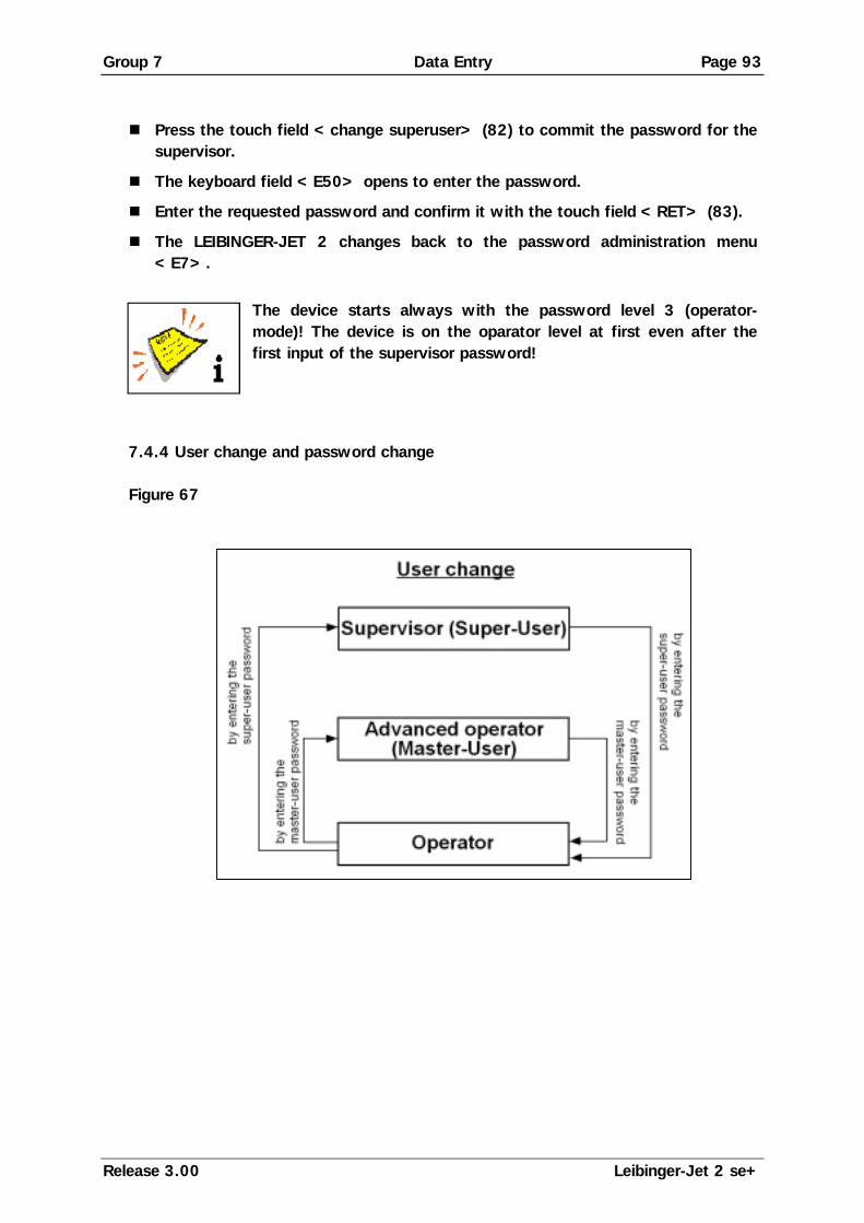
Group 7 Data Entry Page 93
Release 3.00 Leibinger-Jet 2 se+
! Press the touch field <change superuser> (82) to commit the password for the
supervisor.
! The keyboard field <E50> opens to enter the password.
! Enter the requested password and confirm it with the touch field <RET> (83).
! The LEIBINGER-JET 2 changes back to the password administration menu <E7>.
The device starts always with the password level 3 (operator-
mode)! The device is on the oparator level at first even after the first input of the supervisor password!
7.4.4 User change and password change Figure 67

Group 7 Data Entry Page 94
Release 3.00 Leibinger-Jet 2 se+
7.4.4.1 Login as supervisor or advanced operator If the user administration is activated the supervisor and the advanced operator
have always to enter the password because the device is on the operator-level at first.
Manner of proceeding ! Press the touch field <password management> (84) in the menu level <E2>.
! The surface of the password administration <E7> will be called up.
! Press the touch field <enter password> (85).
! The keyboard field <E50> opens to enter one of the given passwords.
! Enter the required password and confirm it with the touch field <RET> (86).
! The selected user will be loged in and the LEIBINGER-JET 2 changes back to the password administration menu <E7>.
7.4.4.2 Change passwords To change existing passwords or to award a password for the advanced operator
(masteruser) you have to proceed as following: ! Press the touch field <password management> (84) in the menu level <E2>.
! The surface of the password administration <E7> will be called up.
! Press the touch field <enter password> (85).
! The keyboard field <E50> opens for input. You have to enter the supervisor-password.
! Enter the required password and confirm it with the touch field <RET> (86).
! The LEIBINGER-JET 2 changes back to the password administration menu <E7>.
! Press the touch field <change superuser> (87) or <change masteruser> (88) to change the certain password.
! The keyboard field <E50> opens to enter a new password.
! Enter the requested password and confirm it with the touch field <RET> (89).
! The LEIBINGER-JET 2 changes back to the password administation menu <E7>. The password is now active.

Group 7 Data Entry Page 95
Release 3.00 Leibinger-Jet 2 se+
Figure 68
The password should have at least 4 characters and should not
exceed 10 characters.
[E7]
86
85
[E50]
Enter password
[E7]
87
88
89
[E50]Enter new password
[E7]
[E2]
84

Group 7 Data Entry Page 96
Release 3.00 Leibinger-Jet 2 se+
7.4.4.3 Logoff as supervisor or advanced operator To log off as supervisor or advanced operator either to reset the LEIBINGER-JET 2
to the operator-mode you have to proceed as following: ! Press the touch field <password management> (90) in the menu level <E2>.
! The surface of the password administration <E7> will be called up.
! Press the touch field <enter password> (91).
! The keyboard field <E50> opens to enter the password.
! Enter the password of the active user again and confirm it with the touch field <RET> (92).
! The LEIBINGER-JET 2 changes back to the password administration menu <E7> and the password level 3 (operator-mode) will be activated.
Figure 69
[E7]
92
91
[E50]
Enter password again
[E7]
[E2]
90

Group 7 Data Entry Page 97
Release 3.00 Leibinger-Jet 2 se+
7.4.5 Password forgotten If the password of the supervisor has been forgotten special proceedings are
required. Please contact the dealer address which is listed in the Chapter Publisher. 7.4.6 Deactivate user-/password administration If the password-/user administration of the LEIBINGER-JET 2 is not required
anymore it can be deactivated any time. Manner of proceeding ! Press the touch field <password management> (93) in the menu level <E2>.
! The surface of the password administration <E7> will be called up.
! Press the touch field <enter password> (94).
! The keyboard field <E50> opens to enter the password.
! The password of the supervisor (super user) has to be entered and has to be confirmed with the touch field <RET> (95).
! The LEIBINGER-JET 2 changes back to the password administration menu. <E7>.
! Press the touch field <change superuser> (96).
! Enter the text „LEIBINGER“ and leave the menu level with the touch field <RET> (97).
! The user administration will be deactivated and the LEIBINGER-JET 2 changes back to the password administration menu <E7>.
! With the <ESCAPE>-button (98) you can get back to the menu level <E2>. All functions are displayed with a bold frame again because they are available without password protection.

Group 7 Data Entry Page 98
Release 3.00 Leibinger-Jet 2 se+
Figure 70
[E7]
95
94
[E50]
Enter password
[E7]
96
97
[E50]Enter text „LEIBINGER“
[E7]
[E2]
93
[E2]
98

Group 7 Data Entry Page 99
Release 3.00 Leibinger-Jet 2 se+
7.5 Print start parameters Figure 71 With the touch field<printstart parameter> (100) the form of the print-out is deter-mined. The print parameter administration surface <E4> is called up. The touch field <ESCAPE> (101) ends the menu and leads back into the previous operation level.
7.5.1 Print delay and print repetition Figure 72
The touch field <print go delay> (102) enables the delay of the print-out by the value entered in mm. At the same time the current value is displayed in the field in addition. The higher the value entered the later the print-out begins. The basic setting, for the entry of the values in mm, is carried out in the programming level <E14> with the touch field <Pulses per mm>.
text PG signal (beginning)
The touch field <print repeat> (103) enables the entry of the number of print-outs,
at the same time the current value is also displayed in the field. Values between 0-255 are admissible.
Example: 000 = single print-out 001 = double print-out
255 = endless repetition
100
[E2]101
102
[E4]
103
print delay
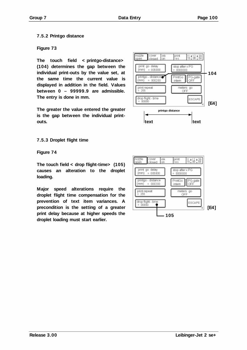
Group 7 Data Entry Page 100
Release 3.00 Leibinger-Jet 2 se+
7.5.2 Printgo distance Figure 73
The touch field <printgo-distance> (104) determines the gap between the individual print-outs by the value set, at the same time the current value is displayed in addition in the field. Values between 0 – 99999.9 are admissible. The entry is done in mm. The greater the value entered the greater is the gap between the individual print-outs.
text text
7.5.3 Droplet flight time Figure 74
The touch field <drop flight-time> (105) causes an alteration to the droplet loading. Major speed alterations require the droplet flight time compensation for the prevention of text item variances. A precondition is the setting of a greater print delay because at higher speeds the droplet loading must start earlier.
[E4]
104
printgo distance
105
[E4]

Group 7 Data Entry Page 101
Release 3.00 Leibinger-Jet 2 se+
7.5.4 Print Go and Print Go Gate Figure 75 The touch field <PrintGo> (106) toggles
between “intern” and “sensor” to select the source of the print go signal. With the “Sensor” setting the print go signal will be generated through an external sensor. With the “Internal” setting the connected sensor is not queried (the print go signal will be generated by the printer).
With the touch field <PG-gate> (107) a further print start condition can be
activated, at the same time the current status “ON” or “OFF” is shown in the field in addition. With the setting “ON” activated the print procedure is only carried out for as long as the queried sensor is under voltage.
Example: Endless print-out of pipes with interrupts between the end of the previos pipe and the beginning of the next pipe.
[E4]
106
107

Group 7 Data Entry Page 102
Release 3.00 Leibinger-Jet 2 se+
7.5.5 Meter go function
Figure 76 With the touch field <Meter-Go> (108) the Leibinger-Jet 2 function will be activated or deactivated. At the same time the current status „ON“ or „OFF“ is displayed.
Function: The function enables to continue the running production for the printing of
continuous goods during a printing stop and enables to continue the print with the correct status after the stop. For this the method steps of the product (entering encoder signals) are displayed in the background. An internal counter in the background calculates therefore the current counter status of the length marking. If a new printing start signal is generated after the print stop by pressing the touch field <printstart>, you will get automatically the correct counter status of the length marking.
Typical applications: ! Length marking of continuous cables
! Length marking of continuous tubes. Note! Already by activating the function <meters go> entering
encoder signals (method steps) will be displayed in the background. To guarantee the correct start value for the first „printing start“ with the function it is absolutely necessary that all counters are reset accordingly.
Pay attention! A correct printing can be only guaranteed if the
printer is not switched off during a printing stop/trouble shooting!
[E4]
108

Group 7 Data Entry Page 103
Release 3.00 Leibinger-Jet 2 se+
Manner of proceeding: ! Choose the function <With Encoder> (110) in the menu level <E8>.
! Activate the function <meters go ON> (111) in the menu level <E4>. The set up <PrintGo> (102) changes automatically to the set up „sensor“ and should be not changed anymore!
! Press the touch field <printgo-distance> (113) to enter the certain value (distance from printing start to printing start) in mm.
! With the <ESCAPE>-button you can leave the menu and you can go back to the menu level <E1>.
! With the touch field <take over > (114) in the menu level <E1> the set up will be taken over to the production.
Observation: The touch field <take over > (114) will be only displayed during open nozzle! Note! To guarantee the correct start value for the first „printing
start“ with the function it is absolutely necessary that all counters are reset accordingly.
Figure 77
[E4]
111
[E8]
110
[E1]
114
112
113

Group 7 Data Entry Page 104
Release 3.00 Leibinger-Jet 2 se+
7.5.6 Pre-defined print stop
Figure 78 With the touch field <stop after x PG> (115) the amount of print-outs are pre-defined and according to this the Leibinger-Jet 2 will release an automatic printing stop. At the same time the entered value is displayed in the field.
Note! Before the restart of the production the product counter has
to be absolutely reset to get a correct result.
[E4]
115

Group 7 Data Entry Page 105
Release 3.00 Leibinger-Jet 2 se+
7.6 Function parameters Figure 79 The touch field <functions parameter> (120) controls the setting of various function parameters. The parameter administration surface <E6> is called up. . The touch field <ESCAPE> (121) ends the menu and leads back to the previous operation level.
7.6.1 Expiration time and shift times Figure 80
The touch field <expiry time set-up> (122) activates the level <E41> for entry of an expiration time. The touch field <shift time set-up> (123) activates the level <E44> for adaptation of the individual shift times.
Expiration time is understood as meaning
the time that elapses until the product is no longer usable. Enter the desired shelf life period via the number block. (This is added to the current date.) Two times can be entered. Return <ret>(124)=take over entry Backspace <bs> (125)=delete the last entry
By activation of the corresponding
<touch field> (126) the times can be entered via the number block appearing.
120
[E2]121
126
[E44]
[E6]
122
123
125
[E41]
124

Group 7 Data Entry Page 106
Release 3.00 Leibinger-Jet 2 se+
7.6.2 Replacements and text sources Figure 81
The touch field <ex. text> (130) controls the text source. At the same time the current status “inactive” or “active” is displayed in the field. With the active setting the text is imported from a connected external data source. If the status inactive has been selected external sources will be ignored.
The touch field <replacements set-up>
(131) activates the selection level <E13>. The selection menu <E13> enables the replacement of the date values entered by letters or names so as to enable a company-specific illustration or coding of the information. The alterations carried out are saved after the entry.
7.6.2.1 Printing with the function “ex. text” By the usage of the function “external text” an easy possibility is provided to send
variable data via the serial interface RS232 without any additional software- or programming works.
Function principle:
Variable data of a fixed text length (string length/field length) can be sent via the RS232 which are placed to the predefined wildcards within the text. Within a text you can define several variable fields of wildcards; ore the wildcards can stand alone also (without additional text). The maximum length of all wildcards is 64 characters; that means for each print-out (PrintGo-signal) you can send and print maximum 64 variable data bytes. For every print-out (PrintGo-signal) always the constant amount of characters have to be transferred which have been also defined as the amount of wildcards (e.g. 4 wildcards are defined ! always necessary to send 4 data bytes per print-out). The characters can include letters and numbers, but should not include control characters as “carriage return” or “line feed”.
[E6]
131
130
[E13]

Group 7 Data Entry Page 107
Release 3.00 Leibinger-Jet 2 se+
Inside the printer there is a input buffer of totally 256 characters available.
For every “PrintGo” the printer will check, if the amount of characters have been entered on the input-buffer, which are given by the amount of the wildcard characters. If enough characters have been received, they will be taken over to the data-buffer and will be printed. If not enough characters have been received, the characters are printed which are taken over to the data-buffer at last (the previous text will be printed again).
Example for text input:
Fix text Variable text/data field Fix text Content XXXX pieces
The input of the fix text (the non-variable part of the text) can be done as usual. After the input of the first text part, the definition of the wildcards for the variable data is carried out: By touching either several touching of the <SHIFT> button, further menus to enter small letters, special characters and additional parameters are called-up. In the menu “Additions” <E60> and with the button <ExText> you can set the required wildcards to implement the variable external data via the interface (wildcards can be any alphanumeric characters; in the shown example the “x” has been used as wildcards). Print-out of our example:
After pressing the button <Printstart> the first four data bytes have to be sent via the RS232 interface => e.g. “1000” After the first “PrintGo”-signal the following text will be printed out:
Content 1000 pieces Now the second data record has to be transferred via the interface (this transmission can already happen during the first print-out) => e.g. “2345” After the next “PrintGo”-signal the following text will be printed out:
Content 2345 pieces

Group 7 Data Entry Page 108
Release 3.00 Leibinger-Jet 2 se+
7.6.3 Reset counters Figure 82
With the touch fields <reset count. 1> (132) and <reset count. 2> (133) the respective counter is reset. (Resetting of counters actually printed out.)
The “counter 1” can also be reseted by an external 24V-signal ona pin 15/X4
(please see chapter 12.2 "Interface layout plan")
[E6]
132
133

Group 7 Data Entry Page 109
Release 3.00 Leibinger-Jet 2 se+
7.6.4 Counter settings Figure 83
With the two touch fields <counter 1 set-up> (134) and <counter 2 set-up> (135) the basic settings of the respective counters are defined. The setting level <E42> is activated.
Figure 84
The touch field <start value> (136) enables the entry of the starting value. Following reaching of the limit value the counter is reset to the starting value.
With the touch field <end value> (137) the limit value can be defined. The starting
value can be increased to any limit value desired. The touch field <increment> (138) defines the increase between the individual print issues. The increase of the counter can be selected between 1-9. The touch field <repeat count> (139) determines the number of prints to be repeated. If no repetition is desired “0” must be entered. The counter can print up to 9999 repetitions. At the same time the values are displayed in addition in the above mentioned fields. The touch field <forward/backward> (140) controls the direction of the counting process i.e. whether the counter is incremented (+) or decremented (-). The touch field <reset> (141) controls the form of the reset. At the same time the activated status „normal“ or „Prod. C.“ is displayed in the field. If the function „Prod. C.“ (with product counter) is activated the counter will be reset when the product counter is reset.
137
[E42]
136
141
138
140
139
[E6]
134 135

Group 7 Data Entry Page 110
Release 3.00 Leibinger-Jet 2 se+
7.6.5 Counter programming To programm a counter you have to proceed as following: (E.g.: A counter with 4 digits should be defined) ! Press the touch field < new text> in the menu level <E3>.
! The “font menu” <E9> is called up.
! After choosing the font the line menu <E15> either the keyboard field <E50> will be displayed if necessary.
! By the touch field <Shift> scroll as long as the menu level <E60> appears.
! Press the touch field <Counter> (142). The Leibinger-Jet 2 changes to the counter definition mode. To indicate that the counter definition mode is active, the display background will be colored black.
! Return with the <Shift>-button (143) to the keyboard field <E50>.
! Input wildcard for the counter. The amount of the wildcards is determined by the number of digits of the counter. The wildcards are already the so-called “start value” of the counter (so e.g. 0005).
! Return with the <Shift>-button (143) to the menu level <E60> again and confirm the input by pressing the touch field <counter> (144) again.
! Escape the menu with the <Shift>-button (143) and you can finish the process in the next possible menu level by pressing the touch field <ESCAPE>.
! With the touch field <take over> (145) in the menu level <E1> the counter will be taken over into the production.
! A safety inquiry with which counter you should go on will be faded-in. Observation: The touch field <take over > will be only displayed during open nozzle!
The parameters of the counter can be selected in the menu level <E6>. The value of the enterd wildcards determines also the “start value” of the counter. For the first start of the production it will be only once from the “start value” (wildcard) to the “initial value”. Afterwards it will be only counted recurrently from the “initial value” to the “end value”.

Group 7 Data Entry Page 111
Release 3.00 Leibinger-Jet 2 se+
Example:
Start value 00 initial value (parameter) 05 end value (parameter)10
Print: 00;01;02;03;04;05;06;07;08;09;10;05;06;07;08;09;10;05;06.....
If the counter should start counting from the beginning from the initial value (e.g. 05) the wildcard has to correspond with the initial value (wildcard value = 05).
Figure 85
145
[E1]
142
143
[E50]Activate counter Input wildcard for counter
Confirm input Taking over to printing process 144
[E60]
[E60]

Group 7 Data Entry Page 112
Release 3.00 Leibinger-Jet 2 se+
7.6.6 Mode normal and reflected Figure 86
The touch field <Mode> (146) controls the printing direction, that means if the text should be printed from forward to behind or from behind to forward. At the same time the current status „normal“ or „reflected “ is displayed.
The mode „reflected“ is used if the back movement of the print head or of the
product is used during the printing process.
Example:
Note! If the button <mode reflected> is activated, it is cogent
necessary to enter also a <print go delay> (see chapter 7.5.1 (print dely and print repetition)). The necessary length of the print go delay is depended of the printing speed and has to be find out by some trials. Recommended is a default value of 5 mm!
[E6]
146

Group 7 Data Entry Page 113
Release 3.00 Leibinger-Jet 2 se+
7.7 Service/test/system parameters Figure 87 With the touch field <service/test/ system-parameter> (150) the system administration surface <E8> is called up. The touch field <ESCAPE> (151) ends the menu and leads back to the previous operating level.
7.7.1 Direct start and time/date Figure 88
With the touch field <direct start> (152) the independent print start of the device can be switched on and off. At the same time the current status “YES” or “NO” is displayed in the field.
I.e. when the print head is opened, the oscillator voltage and the phase set, the ink
jet printer is ready for printing and the LEIBINGER-JET 2 begins the print procedure independently upon receipt of a print start signal. The touch field <time/date set-up>(153) enables the import of date and time. The “entry level” <E40> is called up.
The entry of the current settings of date,
weekday and time can be made. Return <ret>(154)=take over entry Backspace <bs>(155)=deletes the last entry
Observation: The postponement of the date setting is done in hourly steps. The
maximum possible postponement is 23 hours.
155
[E40]
154
150
[E2]151
153
[E8]
152

Group 7 Data Entry Page 114
Release 3.00 Leibinger-Jet 2 se+
7.7.2 Monitoring functions (Control functions) 7.7.2.1 Printgo- and strokego monitoring Monitoring functions are particularly necessary with high printing speeds.
Examples: A Print Go is triggered and is printed. The next Print Go is triggered.
However if the writing procedure has not yet been ended an error notification will be made on the display: „error!!, a printgo occured while a print, was in progress. Prints will be lost. Check also PG-distance.“ If the print speed is too high with the parameters set, stroke errors can occur. The following error notification appears on the display: „error!!, a strokego occured while a stroke, was in progress so strokes will be lost.“ The speed must be reduced or device parameters altered!
Figure 89
With the touch field<control functions> (156) various monitoring functions (control functions) can be activated. The “activation level” <E31> is called up.
With the touch fields <print go control>
(157) and <stroke go control> (158) the functions can be activated or deactivated. At the same time the current status “OFF” or “ON” is shown in the fields.
[E8]
156
158
[E31]
157

Group 7 Data Entry Page 115
Release 3.00 Leibinger-Jet 2 se+
7.7.3 Encoder Figure 90
The touch field <encoder> (159) de-activates or activates this. At the same time the current status „with“ or „without“ is displayed. With encoder print is possible in one or in both directions.
7.7.4 Encoder parameters Figure 91
The current status is displayed in all fields. The touch field <encoder set-up> (160) controls the basic settings of the encoder. The “selection level”<E14> is opened.
With the touch field <lock backward>
(161) the return barring is activated or deactivated. If the return barring is switched on the strokes that are created during any backwards movement are taken into consideration in ensuing forwards movement to control the correct insertion of the text print-out.
With the touch field <encoder directi.> (162) a choice can be made between
direction of rotation to the left or to the right. Encoder signals are only evaluated with a correctly set direction of rotation. The touch field <width> (163) controls the print width of the print-out. The modes “normal” and “extra” are available for selection. In the “extra” mode the print width is doubly wide. Only possible with the “without encoder” setting.
Observation: In the “normal width” mode the device works at a rapid stroke rate,
with “extra width” (extra wide) at a lower stroke rate.
[E8]
159
160
[E8]
163
[E14]
164
162
161

Group 7 Data Entry Page 116
Release 3.00 Leibinger-Jet 2 se+
With the touch field <Pulses per mm> (164) the pulses/revolution indicated on the
encoder can be multiplied by the factor 4 and following the multiplication they can be divided by the distance determined for one revolution.
7.7.5 Job change Figure 92
By switching over to the touch field <JobChan> (170) from “internal” to “external” the possibility is given of changing between 128 jobs during production by means of an external signal. If the “internal” mode is activated external signals for a job change are ignored.
Observation: With activated external job change, jobs can only be edited with a
closed noozle. To change a job by external signals the head must be open. A corresponding signal from the SPC is required.
At the same time the current status “internal” or “external” is displayed in the field. 7.7.5.1 Printing with the function “external job selection” For the usage of the function “external job selection” the printer has to be prepared
as follows: 1.) Delete all jobs:
Please push the following order of buttons: ! “main menu” ! “job management” ! “delete jobs” ! “all jobs” ! ”YES”
2.) Create 128 Default-jobs:
Please push the following order of buttons: ! “main menu” ! “function parameter” ! “replacements” ! “replace figures” ! “ESC” ! “Job management” ! “Factory setting & default job”. After these steps 128 default-jobs have been created automatically (see under “main menu” ! “job management” ! “list all jobs”). The jobs are numbered all the way through with names from “001” up to “128” and the function “external job change” is activated in the single jobs. (This is necessary that no undefined job can be selected by switching over the inputs and that in every job the function “external job change” is already activated).
[E8]
170

Group 7 Data Entry Page 117
Release 3.00 Leibinger-Jet 2 se+
The jobs can be adjusted and overwritten accordingly (= edit and save under the
same name again). They should be saved under a number between “001” and “128”.
Attention!
! If a job is deleted, all other jobs are shifted by one digit ( if e.g. job 031 is deleted, job 032 would be then on position 031 afterwards!!!). An afterwards insert of a new job on this digit where job 31 has been is unfortunately not possible anymore; that means that the arrangement of the job has been always shifted by the amount of the deleted job.
! As the inputs of the jobselect-lines have a very high priority, the head has to be always closed during editing of the job. Otherwise it can happen that the change of a job will be saved in a wrong job (not in the requested job, but in a job which is called by the select inputs right now). If the device is operated by an external software an additional control character can ignore the select lines (please see “interface description of the LJ2”). Due to this the head has not to be closed to edit or save a job as usual.
Overview (Extract) about the signal-state on connector “X4” and the selected
number of the job: Seljob 6 Seljob 5 Seljob 4 Seljob 3 Seljob 2 Seljob 1 Seljob 0
… … Job 18 1 1 0 1 1 1 0 Job 17 1 1 0 1 1 1 1 Job 16 1 1 1 0 0 0 0 Job 15 1 1 1 0 0 0 1 Job 14 1 1 1 0 0 1 0 Job 13 1 1 1 0 0 1 1 Job 12 1 1 1 0 1 0 0 Job 11 1 1 1 0 1 0 1 Job 10 1 1 1 0 1 1 0 Job 9 1 1 1 0 1 1 1 Job 8 1 1 1 1 0 0 0 Job 7 1 1 1 1 0 0 1 Job 6 1 1 1 1 0 1 0 Job 5 1 1 1 1 0 1 1 Job 4 1 1 1 1 1 0 0 Job 3 1 1 1 1 1 0 1 Job 2 1 1 1 1 1 1 0 Job 1 1 1 1 1 1 1 1
0 = Optocouppler not activated 1 = Optocouppler activated For further information about the connection and the pin numbers, please see
group12 chapter Interface layout plan.

Group 7 Data Entry Page 118
Release 3.00 Leibinger-Jet 2 se+
7.7.6 Service/test- and diagnosis functions Figure 93
The field <service/test & diagnostics> (171) activates the „service menu“ <E16>.
7.7.6.1 Summary graph (oscillator voltage curve) In this menu the control of the oscillator voltage regulation can be read. Its
presentation is made in the form of a summary graph.
Settings and alterations! This work must only be carried out by Leibinger service technicians!
Figure 94
The touch field <curve> (172) activates the presentation.
[E8]
171
[E25]
172
[E16]

Group 7 Data Entry Page 119
Release 3.00 Leibinger-Jet 2 se+
7.7.6.2 Motor test This work must only be carried out by trained personnel or by
Leibinger service technicians!
Figure 95
The touch field <motortest> (173) enables the manual setting of the gutter.
By means of tapping on <motor step open> (174) or <motor step close> (175)
the gutter motor is driven and the gutter moves forwards or backwards.
174
[E37]
175
173
[E16]

Group 7 Data Entry Page 120
Release 3.00 Leibinger-Jet 2 se+
7.7.6.3 Charging voltage test/Piezo test Dangerous electrical voltage!
Measurement under voltage has carried out only by electrical experts!
This work must only be carried out by trained personnel or by
Leibinger service technicians!
Figure 96
The touch field <charge test>(176) serves the setting of the charging voltage, the field <piezo test> (177) the setting of the oscillator voltage.
Oscillator voltage setting: issue of a constant oscillator voltage that serves
reconciliation with the oscillation voltage booster (Poti TRM 1). Charging voltage setting: issue of a constant charging voltage for the adjustment of the charging voltage booster (Offset TRM 2, boost TRM3).
[E39][E38]
[E16]
177
176

Group 7 Data Entry Page 121
Release 3.00 Leibinger-Jet 2 se+
7.7.6.4 Software information Figure 97
The touch field <software information> (178) displays the software statuses and
the operating hours counter (179). 7.7.6.5 Permanent bleeding Figure 98
The touch field <const. bleed> (180) starts the permanent bleed of the device.
The status field (181) blinks during the procedure and the notification “Bleed” is displayed. The bleeding can be cancelled at any time by pressing on the touch field <ESCAPE> (182). During this process the visco pump will be activated for 3 sec. every minute to guarantee that the pump will be flushed.
The function permanent bleed can be only activated if the device is
working under the following conditions:
! the ink supply is switched on
! the head cover has been removed.
[E34]
181
[E16]
180
182
[E35]179
178
[E16]

Group 7 Data Entry Page 122
Release 3.00 Leibinger-Jet 2 se+
7.7.6.6 Hydraulic test & parameters This work must only be carried out by trained personnel or by
Leibinger service technicians!
Figure 99
The touch field <hydrauic test & parameter>(190) activates the hydraulic menu <E29>.
If the regulation not inverted is shown,
i.e. is switched off, each individual component can be driven individually. Storage of the values is only possible in the <service > area (191). (for further information see the following page)
With the touch field <bleed>(192) the device can be bleeded. The bleeding is only
carried out as long as the button is active. With the touch field <pressureless> (195) the device can be set in a pressureless operating mode. The function is only available for a deactivated control! The touch field <falltime>(193) starts a new measurement of the current fall time. After approx. 15 seconds the value is updated. The issue of the value is made in milliseconds. In the <display zone> (194) the current system pressure in mbar, the current position of the membrane as well as the mix information (values on the addition of ink and solvent) are shown.
Before exiting with <ESCAPE> it is imperative that the regulation
again be switched on. Incorrect operation can lead to major disturbances to the device!
[E16]
191
[E29]
193
192
194
195
190

Group 7 Data Entry Page 123
Release 3.00 Leibinger-Jet 2 se+
This work must only be carried out by trained personnel or by
Leibinger service technicians!
Figure 100
The touch field <nom. visko> (196) serves the entry of the target fall time in milliseconds, the para-meters are ink and device specific. The touch field <nom. pressure> (197) the print values can be changed. The entry is in mbar.
The touch field <suct.>(198) alters the settings of the suction pump. The standard
values are “144” for devices without head ventilation and “240” for devices with head ventilation.
Observation: The value must be entered in four digit form (e.g.: “0240”). The field <viskor>(199) is required for the entry of the viscosity metre correction
value. The entry is necessary following the replacement of the viscosity metre pipe. The value engraved on the Viskosity meter must be entered here. Viscosity meters without a engraving have the Value 1000. See group Equipping/maintenance.
Language change-over In the field (200) the menu language of the device is displayed! The alternative
menu language of the device is displayed in the field (201). If required you can change to another alternative menu language online (e.g. in case of service) to simplify the communication with the dealer or the LEIBINGER Service – Hotline. The change happens by pressing the touch field <english> (201). You can go back to the standard-menu language with the touch field (200).
Observation: If the device will be switched off after a change of the menu
language the standard-menu language will be loaded automatically if you switch on the high-speed printer again!
Alterations to the parameters already pre-set can lead to serious
functional disturbances!
[E43]
198199
202
197
196
200
201

Group 7 Data Entry Page 124
Release 3.00 Leibinger-Jet 2 se+
The <Intervall time> mode (202) enables the entry of start and limit times at
which the LEIBINGER-JET 2 switches itself on or off automatically for circulation of the ink (e.g.: at 10.25 hours the device switches on / at 10.40 hours the device switches off). This function prevents the drying of the ink and the jets becoming stuck up during operation interruptions. At the same time the set values are displayed in all above mentioned fields.
Entry of ink- and solvent number: For a correct TAG-aquisition it is absolutely necessary to enter the numbers of the
used ink and solvent. Figure 101
The touch field <Input Ink-Solv. No.> (203) activates the entry menu <E70>.
By activation of the corresponding <touch field> (204 or 205) the ink-no. respectively the solvent no. can be entered via the number block appearing.
Alterations to the parameters already pre-set can lead to serious
functional disturbances!
[E43]
203
[E70]
204
205

Group 7 Data Entry Page 125
Release 3.00 Leibinger-Jet 2 se+
7.7.6.7 Touch screen calibration Figure 102
The touch field <touch adjust> (220) opens the calibration menu <E59>.
The display is adjusted with the
<adjust> field (221) and by tapping on the upper calibration point (222) and by subsequent tapping on the lower calibration point (222). The storage is performed with the touch field <save> (223). The calibration points are shown as small squares &.
[E59]
221
223 222
220
[E16]

Group 7 Data Entry Page 126
Release 3.00 Leibinger-Jet 2 se+
7.7.6.8 Service interval Figure 103
The touch field <service interval> (250) opens the service interval menu <E64>.
The following parameters are displayed in
the menu:
! the max. period between two in-spections in working hours (251) either as a period of time (252)
! the working hours since the last inspection (253)
! the total amount of working hours (254) of the device
! the date of the last inspection (255)
The touch field <ESCAPE> (256) ends the menu.
250
[E16]
[E64]
251
253
255
252
254
256

Group 8 Trouble shooting Page 127
Release 3.00 Leibinger-Jet 2 se+
8. Trouble shooting
8.1 General With the help of the error diagnosis the operating personnel should be given the possibility of removing lesser defects. Should it not be possible to achieve a satisfactory result despite the measures carried out or should a lack of clarity prevail please contact the service department or a service technician of your dealer.
Dangerous material in the machine!
Danger of serious damage through burns, skin irriation and poisoning!
8.2 Error notification The error notifications are shown flashing in the status line of the LCD touch display. The error notification texts contains the error denomination, the possible cause of the error or the possible error removal measure. The error is acknowledged by means of touching the touch field <error notification> (status line). Figure 104 Status line with error notifications (specimen illustration)
[E1]

Group 8 Trouble shooting Page 128
Release 3.00 Leibinger-Jet 2 se+
8.3 Error messages Description of the malfunction Trouble shooting activity
Risk of fire!
Combustible gases and liquids cause serious burns. Sources of ignition must be kept away from the print head!
Risk of crushing/piercing!
During the closing movement of the print head your fingers could get caught between deflector unit or nozzle plate and gutter or during the opening movement between housing and gutter. Keep your hands outside of the danger area!
Dangerous electrical voltage!
Contact causes serious damage through an electric shock! The print head must close automatically. Work on the head must only be carried out in a closed state!
Risk of injury!
Ink escapes from the head aperture. Spraying of ink into the eyes can cause blindness. Eye protection is necessary!
This work must only be carried out by trained personnel or by Leibinger service technicians!
Opening/closing of the gutter not carried out correctly. Closing mechanism could be dirty or defective.
Check closing mechanism. Remove ink residue and other contamination with a cleaning brush.
Display message:„an error occured when head moved, gutter moved not correct. Check the mechanics for gutter-movement“
Drop brake-off error! The charging electrode could be dirty. If necessary please clean.
Check charging electrode and clean.
Display message:„not able to adjust drop generation, please check charge electrode for dirt accumulation. Clean, if necessary“
Charging electrode dirty/defective. Please clean or replace.
Check charging electrode and clean or replace.
Display message:„charge elect. Dirty please check charge electrode for dirt accumulation, clean, if necessary“

Group 8 Trouble shooting Page 129
Release 3.00 Leibinger-Jet 2 se+
Phasing error! The charging electrode could be dirty. If necessary please clean.
Check charging electrode and clean.
Display message:„phasing-error, please check charge electrode for dirt accumulation. Clean, if necessary“
Risk of crushing/piercing!
During the closing movement of the print head your fingers could get caught between deflector unit or nozzle plate and gutter or during the opening movement between housing and gutter. Only carry out cleaning and service work with the machine placed idle. Remove mains plug!
High voltage current too high. Please check the deflector plates for dirt or dampness.
Check deflector plates.
Display message:„hv-current to high check deflection plate for dirt or humidity“

Group 8 Trouble shooting Page 130
Release 3.00 Leibinger-Jet 2 se+
Description of the malfunction Trouble shooting activity Dangerous material in the machine!
Read the safety leaflets and the regulations on personal safety equipment!
Risk of injury!
Spraying of ink into the eyes can cause blindness. Prior to the opening of the device eye protection must be put on!
Risk of injury!
Upon contact the contents causes skin irritation. Protective equipment is necessary!
It is imperative that the instructions on the subject of handling inks and solvents (thinners) in the groups Safety instructions and Accident prevention are observed!
Ink will soon be empty! Please refill. Refill ink. Display message:„Ink tank is low level please refill ink“ Solvent will soon be empty! Please refill. Refill solvent. Display message:„Solvent tank is low level please refill solvent“ Ink/solvent not from Leibinger. Please remove bottle!
Only use original ink and solvent made by Leibinger.
Display message:„ Leibinger Ink/Solvent not detected! Please remove bottle.“
Wrong ink/solvent! Please remove bottle. The selected ink or solvent may not be used in this device!
Display message:„ Wrong Ink/Solvent! Please remove bottle.
Ink/solvent already decremented on ...., please activate with new bottle.
The selected consumable medium has already been decremented.
Display message:„ Expiration date reached! To activate the Ink/Solvent, place the bottle to the TAG-Reader and press “Activate”.

Group 8 Trouble shooting Page 131
Release 3.00 Leibinger-Jet 2 se+
Description of the malfunction Trouble shooting activity
The content is under pressure even if the device has been disconnected from the mains supply!
Ink under pressure can spray out. Prior to opening disconnect the device from the mains supply and let off the pressure!
Risk of injury!
Spraying of ink into the eyes can cause blindness. Prior to the opening of the device eye protection must be put on!
This work must only be carried out by trained personnel or by Leibinger service technicians!
Leak in the hydraulics, please check hydraulics immediately!
Disconnect device from the mains supply and check hydraulics for leaks!
Display message:„leakage found in the hydraulic area, please check hydraulic immediately“
Defective viscosity measurement! Please check viscosity pump and metre or call the Leibinger service department.
Disconnect device from the mains supply! Check the viscosity pump and the viscometer. Observe the instructions in the group Servicing!
Display message:„faulty visco-measurement please check visco-pump and –meter or call our perfect Leibinger service“
Ink conveying defective. Please check main pump, pressure tank and their connections.
Disconnect device from the mains supply! Check the main pump, the pressure tank and the connections. Check the position of the ink switch!
Display message:„pressure fault please check air pump and all connections“
Pressure disturbance! Please check compressor, pressure tank and all connections.
Disconnect device from the mains supply! Check the compressor, the pressure tank and the connections.
Display message:„pressure fault“ please check air pump and all connections“

Group 8 Trouble shooting Page 132
Release 3.00 Leibinger-Jet 2 se+
Description of the malfunction Trouble shooting activity
Bleeding Carry out bleeding. Display message:„pressure fault“ please check air pump and all connections“
Blade synchronisation Display message:„knife-synchronisation“
Printgo error/printgo distance error! No new print must be started during the printing process.
Alter setting parameters.
Display message:„error!!, a printgo occured while a print was in progress. Prints will be lost. Check also PG-distance“
Strokego error! Strokes were lost during the printing process.
Alter setting parameters.
Display message:„error!!, a strokego occured while a stroke was in progress so strokes will be lost.“
8.4 Other causes of errors The following list illustrates additional possible sources of errors that are not shown in the display with any error notification. Description of malfunction Trouble shooting activity
Device cannot be switched on ! Touch display pressed for too short a time (min. 2 sec.)
! Mains plug not plugged in ! Mains cable or display defective ! Mains fuse(s) defective (Observe the instructions in the group Equipping/maintenance!)
Data transmission from PC not possible Connection cable not connected or defective
Print head not working although no error displayed
! Status field <Print> is on “No” ! No data entry present ! Head cover of the print head not
assembled or incorrectly assembled ! Product sensor not connected or set
incorrectly ! Basic settings incorrect
Suction pump achieving no power ! Value incorrectly set -menu level <E43> ! Cleaning is necessary, see chapter
Miscellaneous cleaning work

Group 9 Equipping/maintenance Page 133
Release 3.00 Leibinger-Jet 2 se+
9. Equipping/maintenance
9.1 Equipping/operation 9.1.1 Refilling of ink and solvent 9.1.1.1 General information
Dangerous material in the machine!
Danger of serious damage through burns, skin irriation and poisoning!
Dangerous material in the machine!
Read the safety leaflets and the regulations on personal safety equipment!
Risk of injury!
Spraying of ink into the eyes can cause blindness. Prior to the opening of the device eye protection must be put on!
Risk of injury!
Upon contact the contents causes skin irritation. Protective equipment is necessary!
The storage containers for ink and solvent are installed beneath the cover flap of the
refill unit (see illustration below). The containers are always without pressure and can be opened in any condition of the device including during production. Following refilling the containers must be closed again carefully.
Important! The containers are monitored by filling level sensors. In
the event of the minimum filling level being under-achieved an optical and acoustic request to refill is made. If no acknowledge-ment of the refill alarm is made within 10 minutes, the LEIBINGER-JET 2 will stop the production and close the jet and the device will switch off.

Group 9 Equipping/maintenance Page 134
Release 3.00 Leibinger-Jet 2 se+
Figure 105
Instruction label see inside of the housing cover
Storage containers (view with cover folded back)
1 – Storage container “Ink” 2 – Storage container “Solvent”
The storage containers must not be overfilled!
Only fill up to max. 2/3! Following filling the containers must again be closed carefully.
For 8 hour operation the storage containers should be at least half filled as with
most applications the ink consumption is low (1 litre enables the printing of up to 100 million characters depending on the matrix and the diameter of the jet). Depending on the ink, ambient temperature and humidity the consumption of LEIBINGER solvent can be between 20-100 ml/8 hours. With higher temperatures in shift operation LEIBINGER solvent should therefore be checked or refilled daily.
At this point we wish to make explicit reference to the fact that it
is only when using solvent and ink from Paul Leibinger GmbH & Co. KG that the optimum operating characteristics can be achieved. In the event of use of other inks and solvents all guarantee entitlements shall cease to apply.
1
2

Group 9 Equipping/maintenance Page 135
Release 3.00 Leibinger-Jet 2 se+
9.1.1.2 TAG reader and TAG identifier Inks and solvent made by Paul Leibinger GmbH & Co. KG are identified by TAGs.
The TAG is located below the label of each re-fill bottle (see fig. below). The LEIBINGER-JET 2 is equipped with a TAG reader to read the TAG codes.
Figure 106
1 – TAG reader 2 – TAG area of the Re-fill bottle TAG reader and TAG identifier
9.1.1.3 TAG reading, TAG information, TAG activating and filling the device Figure 107
TAG reading
1. TAG reading, TAG information and TAG activating: ! Place the re-fill bottle (ink or solvent) with the label side in front of the TAG
reader.
1
2

Group 9 Equipping/maintenance Page 136
Release 3.00 Leibinger-Jet 2 se+
! If necessary, slowly move the re-fill bottle back and forth in front of the TAG
reader until TAG reading is complete.
! After a successful acquisition the following message appears on the LCD-Touch display. (The following displayed messages refer to the filling up of the LEIBINGER-JET 2 with ink. For the filling up with solvent the messages are changed accordingly).
! The message provides information on the contents of the re-fill bottle:
1. The item no. of the ink or solvent
2. The use-by date of the ink or solvent
3. The delivery date of the ink or solvent
! If the wrong re-fill medium was selected, the procedure can be ended by pressing the <Not Active> (5) touch field.
! If the selected medium is to be poured in, the <Activate> (4) touch field must be pressed. For this the bottle has to stay in front of the TAG-reader.
! If the activation has been carried out successfully the TAG of the bottle will be devaluated. The successful activation is indicated with two short acoustic signals and the following display message.
21
3
4 5

Group 9 Equipping/maintenance Page 137
Release 3.00 Leibinger-Jet 2 se+
2. Filling the device with solvent: ! Carry out the filling up of the solvent reservoir as described in chapter 9.1.1.1
Refilling of ink and solvent (General information) and confirm the filling up with the touch field <OK> (6).
Note! For the solvent you have absolutely to fill in the complete
bottle because the bottle will be devaluated and can be not activated anymore !
3. Filling the device with ink: ! Carry out the filling up of the ink reservoir tank as described in the chapter
9.1.1.1 Refilling of ink and solvent (General information) and confirm the filling up with the Touch field <OK> (6). You have to fill in only the half of the bottle.
Note! To fill up the ink you should only fill in the half of the bottle
because the content of the ink reservoir is lower than the content of the ink bottle. Due to this the ink reservoir tank could overflow!
9.1.1.4 Consumable medium with elapsed use-by date ! If the expiry date of a consumable medium has been reached the following
message appears on the LCD-Touch display. (The following displayed message refers to the filling up of the LEIBINGER-JET 2 with ink. For the filling with solvent the message is changed accordingly).
! The message provides information on the contents of the re-fill bottle:
1. The item no. of the ink or solvent
2. The use-by date of the ink or solvent
3. The delivery date of the ink or solvent
6

Group 9 Equipping/maintenance Page 138
Release 3.00 Leibinger-Jet 2 se+
! If a different re-fill medium is to be used, the procedure can be ended by means of the <Not Active> (5) touch field.
! If the selected medium should be filled in even if the expiry date has been reached you have to press the touch field <Activate> (4). For this the bottle has to stay in front of the TAG-reader.
! The bottle will be now activated and the TAG devaluated. The following message is indicated on the display.
! Carry out the filling up of the reservoir tank as described in the chapter 9.1.1.1
Refilling of ink and solvent (General information) and confirm the filling with the touch field <OK> (6).
Note!
To fill up solvent you have to fill in the complete tank because the bottle will be devaluated and can be not activated anymore! To fill up ink you have to fill in only the half of the bottle because the content of the ink tank is lower than the content of the bottle! Filling the device with elapsed ink or solvent can lead to poor printing results and production down-time!
11: 05: 32 16. 02. 04
nozzle closed
cover open
print No
Not Activate
Ink Nr.: 70000-00001 Expiration date: 20.12.2003 Distribution date: 01.02.2002
Expiration date reached! To activate the Ink/Solvent,
hold bottle to the TAG-Reader and press „Activate“.
Activate
213
4 5
ink off
6

Group 9 Equipping/maintenance Page 139
Release 3.00 Leibinger-Jet 2 se+
9.1.1.5 TAG Error messages More detailed information on this subject can be found in the chapter entitled Error
messages/error notifications. 9.1.1.6 Other TAG messages and Repair TAG 1. Refilling without TAG activation: ! If ink or solvent has been filled in without activating the bottle the following
message appears on the LCD-Touch display.
Ink Solvent
! If the subsequent activation should not be carried out you can finish the process by pressing the button <Not Activate> (1). If ink has been filled in of an already used or activated bottle no further activation is required !
Note: If a required activation will be not carried out the LEIBINGER-JET 2 carries on working at the moment but will be shut down after process of given criterions. This consequences should be noted!
! If the activation should be carried out the used bottle should be put in front of the TAG-reader.
! The certain bottle will be activated subsequently and the TAG will be devaluated. The succesful activation is indicated by two short acoustic signals and the certain display message.
1

Group 9 Equipping/maintenance Page 140
Release 3.00 Leibinger-Jet 2 se+
2. Devaluated refill bottle: ! If ink or solvent has been filled in without activating the bottle the following
message appears on the LCD-Touch display. (The following displayed message refers to a bottle with ink. For a bottle of solvent the solvent No. is indicated instead of the ink No.).
3. Repair-TAG: A repair-TAG will be available if a bottle has been devaluated by mistake or if the
LEIBINGER-JET 2 has been shut down. You find the repair-TAG under the cover flap of the refilling unit by delivery of the device.
Note! The repair-TAG can only be activated once!

Group 9 Equipping/maintenance Page 141
Release 3.00 Leibinger-Jet 2 se+
9.1.2 Refill messages The refill tanks of the LEIBINGER-JET 2 are checked by level sensors. If the minium
level is remained an optical and acoustic signal ask you to refill. 9.1.2.1 Messages in the standard operation If a refill message has been generated the production menu will be called up
automatically and the refill message is shown flashing in the status line of the display (1). Solvent Ink After acknowledgement of the message additional information is indicated on the display. By pressing the Touch-field <ESCAPE> (2) the production menu is indicated again.
You will find further information regarding the TAG-handling, filling
the reservoir tanks as well as regarding further TAG-messages in the chapter 9.1.1 Refilling of ink and solvent and so on.
Note!
To refill the solvent you have to fill in the complete bottle because the bottle is devaluated and can be not activated anymore! To refill the ink you have to fill in only the half of the bottle because the content of the ink tank is lower than the content of the bottle!
1
2

Group 9 Equipping/maintenance Page 142
Release 3.00 Leibinger-Jet 2 se+
9.1.2.2 Messages in the “host operation” If the LEIBINGER-JET 2 is in the “host operation” (external control via the interface
RS232) the refill messages are different because no TAG-activation has been carried out in this operating mode. That means the user can only refill ink or solvent but cannot carry out any activation of the refill tank(s). This process will be identified and saved. If a refill message has been generated it is indicated flashing in the status line of the display (1). Example view: Ink refilling message After acknowledgement of the message an additional information is indicated on the display. By pressing the touch field <OK> (2) you can change again to the host menu. If the device will be started again after such refilling process a certain message to activate the TAG will be indicated.
You will find further information regarding TAG-handling, refilling
the reservoir tank as well as regarding further TAG-messages in the chapter 9.1.1 Refilling of ink and solvent and so on.
1 11: 05: 32 16. 02. 04
nozzle closed
cover open
print No
!!! Attention !!! Please fill in the half bottle, into the ink tank. During the
production the activation of a new bottle is not possible. To activate
the bottle, the printer has to be offline.
OK 2
ink off

Group 9 Equipping/maintenance Page 143
Release 3.00 Leibinger-Jet 2 se+
Note!
If ink of an already used and activated bottle has been filled in no further activation is required! To refill solvent you have to fill in the complete bottle because the tank is devaluated and can be not activated anymore! To refill ink you have only to fill in the half of the bottle because the content of the ink tank is lower than the content of the bottle!

Group 9 Equipping/maintenance Page 144
Release 3.00 Leibinger-Jet 2 se+
9.2 Guarantee The guarantee conditions for the LEIBINGER-JET 2 can be seen from the order confirmation. At this point we wish to make explicit reference to the fact that it is only when using solvent and ink from Paul Leibinger GmbH & Co. KG that the optimum operating characteristics can be achieved. In the event of use of other inks and solvents all guarantee entitlements shall cease to apply. 9.3 Service/maintenance Dangerous material in the machine!
Read the safety leaflets and the regulations on personal safety equipment!
9.3.1 Daily servicing work The daily servicing work includes the checking of the print head and in particular of
the deflector unit, the charging electrode as well as of the guides for dirt. If necessary the components must be cleaned as described in the chapter Cleaning. Likewise the filling level of the two storage containers for LEIBINGER ink and LEIBINGER solvent must be checked. Information on the Refilling of ink and solvent can be found in the chapter Equipping.
9.3.2 Weekly servicing work The weekly servicing work includes the checking of the spindles and of the guides
of the nozzle seal for dirt. If necessary the components must be cleaned as described in the chapter Cleaning. Likewise the nozzle seal must be checked.
9.3.2.1 Lubrication Dangerous electrical voltage!
Contact causes serious damage through an electric shock! Disconnect the device from the mains supply prior to opening. Remove mains plug!

Group 9 Equipping/maintenance Page 145
Release 3.00 Leibinger-Jet 2 se+
Risk of fire!
Combustible gases and liquids cause serious burns. Sources of ignition must be kept away from the print head!
Risk of injury!
Ink escapes from the head aperture. Spraying of ink into the eyes can cause blindness. Eye protection is necessary!
This work must only be carried out by trained personnel or by Leibinger service technicians!
The lubrication of the spindles and of the guides of the nozzle seal is not absolutely
necessary, however it ensures easier movement of the gutter. Lubrication with oil also prevents the depositing of ink that can block the gutter during opening or closing of the nozzle seal. A commercially available oil can be used for lubrication. Oil must not get into the cgutter (back absorption)!
9.3.2.2 Nozzle sealing Dangerous electrical voltage!
Contact causes serious damage through an electric shock! Disconnect the device from the mains supply prior to opening. Remove mains plug!
Risk of fire!
Combustible gases and liquids cause serious burns. Sources of ignition must be kept away from the print head!
Risk of injury!
Ink escapes from the head aperture. Spraying of ink into the eyes can cause blindness. Eye protection is necessary!
This work must only be carried out by trained personnel or by Leibinger service technicians!

Group 9 Equipping/maintenance Page 146
Release 3.00 Leibinger-Jet 2 se+
The sealing point between nozzle and gutter should be checked in particular before
extended idle periods. A non-tight nozzle seal leads to blocking of the suction extraction lead during extended idle periods.
Testing procedure With the nozzle seal closed, apply a couple of drops of solvent to the sealing point
with the spray bottle. If the seal is not tight, the solvent will be sucked into the suction extraction lead. In this case damage to the O-ring must be assumed. To replace the O-ring the cross head screws of the clamping plate must be loosened. Subsequently the screws must be tightened again and the tightness must be checked again as described above.
Figure 108
1 – Nozzle plate 2 – Knurled screw 3 – Bar 4 – Drop production unit 5 – Clamping plate 6 – O-ring
Removal and installation or replacement of the nozzle plate You should proceed as follows when removing or installing the nozzle: Risk of crushing/piercing!
During the closing movement of the print head your fingers could get caught between deflector unit or nozzle plate and gutter or during the opening movement between housing and gutter. Keep your hands outside of the danger area!
! Close the nozzle.
! Switch off the ink using the ink switch in the print head (switch downwards).
! Swivel deflector unit upwards and secure with toggle lever.
! Open the nozzle (move gutter forwards).
! The nozzle plate can be removed following undoing of the knurled screw and swivelling away of the bar.

Group 9 Equipping/maintenance Page 147
Release 3.00 Leibinger-Jet 2 se+
! Cleaning of the nozzle only with LEIBINGER solvent against and in the direction
of the current or with the help of an ultrasound bath and subsequent blowing out with compressed air. Further information on this subject area can be found in the chapter Cleaning.
! Installation of the cleaned or new nozzle plate.
! The bar that fixes the nozzle plate must be swivelled downwards so that the nozzle plate is fixed centrally.
! The knurled screw can be tightened as far as the stop (by hand only, without tools).
! The ink can be switched on with the ink switch (switch upwards). When so doing, attention should be paid to the fact that in the event of incorrect installation ink can spray out. Observe safety instructions!
! If the ink jet enters the gutter, the correct position of the jet in the gutter must be checked and if necessary a fine adjustment must be done with the adjusting screws. Insufficient or incorrect cleaning leads to jet jumping with repeated switching on and off of the ink switch. Only if the cleaning has been carried out correctly will the ink jet always enter the gutter at the same point. Further information on the adjustment of the ink jet can be found in the chapter Other servicing work.
! Following the check of the above mentioned points the gutter can be closed and the deflector unit swivelled downwards carefully by release of the toggle lever.
! Prior to starting the print operation the print head should be checked once again and possibly cleaned. Further information on this subject area can be found in the chapter Cleaning. Following an extended idle period it is expedient to switch the device on and off again in order to trigger a bleeding procedure.
9.3.3 Annual servicing work The manufacturer recommends a regular servicing interval of 6–12 months. Integral
parts of this servicing are: ! Replacement of filter elements and ink
! Replacement of the O-rings for filter and nozzle seal

Group 9 Equipping/maintenance Page 148
Release 3.00 Leibinger-Jet 2 se+
9.3.3.1 Filter replacement and ink change The content is under pressure even if the device has been
disconnected from the mains supply!
Ink under pressure can spray out. Prior to opening disconnect the device from the mains supply and let off the pressure!
Dangerous material in the machine!
Danger of serious damage through burns, skin irriation and poisoning!
Risk of injury!
Spraying of ink into the eyes can cause blindness. Prior to the opening of the device eye protection must be put on!
This work must only be carried out by trained personnel or by Leibinger service technicians!
With non-pigmented inks the filter insert must be replaced annually, with pigmented
inks every six months. Filter insert, order no: 54-002326 KA With the filter change the entire ink content of the device must be replaced and disposed of properly. The corresponding safety information leaflets DIN 52900 and the country specific disposal regulations must be observed!
Manner of procedure: ! Place the LEIBINGER- JET 2 in operating mode “Nozzle closed” (1) and “Ink
switch on” (2).
! Deactivate the regulation (3) in the menu level <E29> (main menu ! service/test/system parameter ! service/test & diagnostics ! hydraulic test & parameter).
! Press the button “pressureless” (4) in the menu level <E29> and wait for a while until the values for the “membrane” and “pressure” (5) moving towards ~“0“.

Group 9 Equipping/maintenance Page 149
Release 3.00 Leibinger-Jet 2 se+
! The LEIBINGER- JET 2 is without pressure and must be disconnected from the mains supply. Remove mains plug!
Figure 109
! Undo the 2 Allan screws and remove the entire pressure tank if the tube connections allow this (picture sequence 1).
! Place the collection tub underneath the tank and remove both connections for the viscosity regulation. The ink will run out. If necessary all hydraulic connections can be removed.
! Unscrew the 8 continuous Allan screws that hold the pressure tank together (picture sequence 2) and remove the lower half of the housing downwards. The membrane flange must not be loosened!
! Pull off the filter and slide on the new filter (picture sequence 3).
! Clean any possible dirt in the filter housing with thinner. Examine the O-ring for damage and clean. If necessary replace.
Unscrew only the continuous allan screws!
4
5
1
2
3

Group 9 Equipping/maintenance Page 150
Release 3.00 Leibinger-Jet 2 se+
! Before closing pay attention to the correct seat of the O-ring and check whether
the agitator rod in the lower part is lying on the floor (picture sequence 4).
! Close pressure housing and tighten with the corresponding screws.
! Again insert the pressure tank and attach the tube connections.
! The further steps are carried out in an empty condition as with the initial commissioning. Further information can be found in the chapter Start up!

Group 9 Equipping/maintenance Page 151
Release 3.00 Leibinger-Jet 2 se+
9.3.4 Other servicing work 9.3.4.1 Adjusting the ink jet in the gutter Dangerous electrical voltage!
Contact causes serious damage through an electric shock! Disconnect the device from the mains supply prior to opening. Remove mains plug!
Risk of fire!
Combustible gases and liquids cause serious burns. Sources of ignition must be kept away from the print head!
Risk of injury!
Ink escapes from the head aperture. Spraying of ink into the eyes can cause blindness. Eye protection is necessary!
This work must only be carried out by trained personnel or by Leibinger service technicians!
If you use a new nozzle, it is necessary to readjust the ink jet. This can be carried
out with adjusting screws (cross head) located on the holder of the deflector unit by screwing in or out (swivelling upwards or downwards or to the left or right) (see following illustration). In order to achieve a better contrast in poor light it is helpful if you first of all clean the guttere and the print head chassis with Leibinger solvent and hold white paper behind or below the gutter. Further information on this subject area can be found in the chapter Cleaning.
The adjustment of the ink jet must first of all be performed vertically then horizontally!
The correct jet position can be seen from the following illustration!
The correct position of the ink jet must be checked in order to ensure that no deposits develop in the gutter.

Group 9 Equipping/maintenance Page 152
Release 3.00 Leibinger-Jet 2 se+
Figure 110
Should deposits develop on the gutter without print operation, the ink jet is too tight against the outside of the gutter in the horizontal direction. Should deposits develop on the gutter with print operation, the ink jet is too far in the middle of the gutter in the horizontal direction. With special applications, e.g. very small fonts, the position can be readjusted following consultation with the manufacturer.
9.3.4.2 Replacement of the main pump The content is under pressure even if the device has been
disconnected from the mains supply!
Ink under pressure can spray out. Prior to opening disconnect the device from the mains supply and let off the pressure!
Dangerous material in the machine!
Danger of serious damage through burns, skin irriation and poisoning!
Risk of injury!
Spraying of ink into the eyes can cause blindness. Prior to the opening of the device eye protection must be put on!
Jet adjusting screw (left/right)
Jet adjusting screw (up/down)
(Jet position)
Jet position in the gutter (seen from the direction of the jet)
(Gutter)

Group 9 Equipping/maintenance Page 153
Release 3.00 Leibinger-Jet 2 se+
This work must only be carried out by trained personnel or by Leibinger service technicians!
Figure 111
Main pump (54-002-001 S)
! Place the LEIBINGER-JET 2 in the operating mode “Nozzle closed” (1) and “Ink
switch on” (2).
! Deactivate the regulation (3) in the menu level <E29> (main menu ! service/ test/system parameter ! service/test & diagnostics ! hydraulic test & parameter).
! Press the button “pressureless” (4) in the menu level <E29> and wait for a while until the values for the “membrane” and “pressure” (5) moving towards ~“0“.
! The LEIBINGER-JET 2 is now without pressure and must be disconnected from the mains supply. Remove mains plug!
! Place a collection tub underneath and detach the tube connections. Escaped ink must be disposed of properly. The corresponding safety leaflets DIN 52900 and the country specific disposal regulations must be observed!
! Detach electrical connection cable and remove main pump.
! Place the new main pump in again and attach the tube connections as well as the electrical connection cable.
! As with the initial commissioning the further steps are performed in the empty condition. Further information can be found in the chapter Start up!
4
5
1 2
3

Group 9 Equipping/maintenance Page 154
Release 3.00 Leibinger-Jet 2 se+
9.3.4.3 Replacement of the battery and fuse Dangerous electrical voltage!
Contact causes serious damage through an electric shock! Disconnect the device from the mains supply prior to opening. Remove mains plug!
Dangerous electrical voltage!
Parts of the device are still under voltage after blowing the protecting device! Disconnect the device from the mains supply prior to opening. Remove mains plug!
Caution – risk of explosion!
Risk of explosion in the event of incorrect replacement of the battery. Replace only with an identical battery or with an equal value battery type in accordance with the recommendations of the manufacturer! The instructions of the battery manufacturer must be observed when disposing of the battery!
Replacement of the battery! This work must only be carried out by trained personnel or by Leibinger service technicians!
The battery and the fuse are situated in the electronics housing on the controller
board or on the mains part. If necessary the fuse and the battery must be replaced. When changing the battery it is imperative that the Safety instructions as well as the Disposal instructions of the battery manufacturer are observed!
Figure 112
1 – Battery, lithium, 3.2 VDC (54-003 032 KA) 2 – Fuse 1,6 H (54-003 339 KA)
1
2

Group 9 Equipping/maintenance Page 155
Release 3.00 Leibinger-Jet 2 se+
9.3.5 Servicing work with more difficult operating conditions With more difficult operating conditions such as extremely high or low ambient
temperature, heavy dust levels or high humidity etc., some servicing work should be carried out earlier. The time must however be estimated on the basis of experience values. This applies above all for:
! Changing the ink (high water content or destruction of the binding agent)
! Replacement of the filter insert

Group 9 Equipping/maintenance Page 156
Release 3.00 Leibinger-Jet 2 se+
9.4 Cleaning 9.4.1 Daily cleaning work 9.4.1.1 Cleaning the print head Dangerous electrical voltage!
Contact causes serious damage through an electric shock! Disconnect the device from the mains supply prior to opening. Remove mains plug!
Risk of fire!
Combustible gases and liquids cause serious burns. Sources of ignition must be kept away from the print head!
Risk of injury!
Ink escapes from the head aperture. Spraying of ink into the eyes can cause blindness. Eye protection is necessary!
Risk of injury!
Upon contact the contents causes skin irritation. Protective equipment is necessary!
The print head must be checked daily and cleaned in the event of recognisable dirt through penetrating dust or ink. In this respect high release of solvent vapours should be avoided through the economical use of Leibinger solvent (corresponding to the Leibinger ink). This is achieved through applying the Leibinger solvent to fluff-free paper with the spray bottle and wiping off the parts to be cleaned with this. Direct spraying off of the print head with solvent should only be carried out with very major dirt and should be limited to the front part of the print head. Following intensive cleaning the nozzle seal must be lubricated with a commercially available oil (spindle and guide). Oil must not get into the gutter (back absorption)! Solvent dropping down must be collected using a solvent resistant metal vessel and disposed of properly.
This work must only be carried out by trained personnel or by Leibinger service technicians!

Group 9 Equipping/maintenance Page 157
Release 3.00 Leibinger-Jet 2 se+
9.4.1.2 Cleaning the deflector unit and gutter Dangerous electrical voltage!
Contact causes serious damage through an electric shock! Disconnect the device from the mains supply prior to opening. Remove mains plug!
Risk of fire!
Combustible gases and liquids cause serious burns. Sources of ignition must be kept away from the print head!
Risk of injury!
Ink escapes from the head aperture. Spraying of ink into the eyes can cause blindness. Eye protection is necessary!
Risk of injury!
Upon contact the contents causes skin irritation. Protective equipment is necessary!
Figure 113
1 – Charging electrode 2 – Deflector plate 3 – Gutter Deflector unit
Clean gutter (3) carefully with solvent! The deflector unit consists of a charging electrode (1) and a deflector plate (2). To clean the deflector plate the gutter must first of all be closed in order to prevent damage to the nozzle seal. Only close head with clean gutter!
Risk of crushing/piercing!
During the closing movement of the print head your fingers could get caught between deflector unit or nozzle plate and gutter or during the opening movement between housing and gutter. Keep your hands outside of the danger area!
1 2
3

Group 9 Equipping/maintenance Page 158
Release 3.00 Leibinger-Jet 2 se+
After this the deflector unit can be swivelled upwards and secured with the toggle
lever. The cleaning of the deflector unit can then be started. In this respect it is helpful to first of all position the dry cleaning cloth between the parts to be cleaned and only then to spray with LEIBINGER solvent. After cleaning dry the deflector unit (e.g. with compressed air). Subsequently the deflector unit can again be swivelled carefully downwards following release of the toggle lever. It is not necessary to use tools for this.
This work must only be carried out by trained personnel or by Leibinger service technicians!
9.4.2 Weekly cleaning work 9.4.2.1 Cleaning of the spindle and guides of the nozzle seal Dangerous electrical voltage!
Contact causes serious damage through an electric shock! Disconnect the device from the mains supply prior to opening. Remove mains plug!
Risk of fire!
Combustible gases and liquids cause serious burns. Sources of ignition must be kept away from the print head!
Risk of injury!
Ink escapes from the head aperture. Spraying of ink into the eyes can cause blindness. Eye protection is necessary!
Risk of injury!
Upon contact the contents causes skin irritation. Protective equipment is necessary!
This work must only be carried out by trained personnel or by Leibinger service technicians!

Group 9 Equipping/maintenance Page 159
Release 3.00 Leibinger-Jet 2 se+
The spindle (1) and the guides (2) of the nozzle seal should be cleaned at least once
per week with the corresponding solvent. Figure 114
1 – Spindle 2 – Guides
9.4.3 Other cleaning work 9.4.3.1 Cleaning the nozzle Dangerous electrical voltage!
Contact causes serious damage through an electric shock! Disconnect the device from the mains supply prior to opening. Remove mains plug!
Risk of fire!
Combustible gases and liquids cause serious burns. Sources of ignition must be kept away from the print head!
Risk of injury!
Ink escapes from the head aperture. Spraying of ink into the eyes can cause blindness. Eye protection is necessary!
Risk of injury!
Upon contact the contents causes skin irritation. Protective equipment is necessary!
This work must only be carried out by trained personnel or by Leibinger service technicians!
1 2

Group 9 Equipping/maintenance Page 160
Release 3.00 Leibinger-Jet 2 se+
Should ink dry in the nozzle as a result of operating errors or should the nozzle be
blocked with dirt particles or the ink jet not enter the gutter, the nozzle must be dismantled and cleaned. Experience shows that the cleaning of the nozzle with LEIBINGER solvent and blowing out with compressed air against the direction of the current is sufficient to free the nozzle. Should this not be possible, the nozzle must be cleaned in an ultrasound bath (covered with LEIBINGER solvent) for at least 5 minutes and subsequently again blown out with LEIBINGER solvent and compressed air. Ultrasonic bath, order no: 54-002 347 K In this respect it should be noted that the adjusted position of the ink jet cannot alter suddenly. If the ink jet no longer enters the gutter this is usually due to the fact that dirt particles or dried ink are situated in the nozzle intake.
Figure 115
1 – Nozzle sealing (O-Ring) 2 – Nozzle stone 3 – Nozzle plate 4 – Clamping plate
In case of stubborn ink residue it can be permitted to remove the residue with a
tooth-pick (wooden only). Caution: Risk of damage! For this the nozzle is first of all rinsed out with LEIBINGER solvent and the jet is blown dry from both directions with compressed air. Thereafter you move to the nozzle stone (2) from both sides with a tooth-pick (wooden only). By means of light pressure and turning the ink remains are detached from the nozzle stone. Subsequently the nozzle is again rinsed with LEIBINGER solvent and blown out with compressed air.
Nozzle adjustment: once set correctly the nozzle retains its
position. In the event of the jet varying from the normal position: Clean nozzle until old position sets itself again automatically.

Group 9 Equipping/maintenance Page 161
Release 3.00 Leibinger-Jet 2 se+
Checking of the jet cleaning carried out
With repeated switching of the ink flow valve (by pressing of the ink on/off switch) the ink jet must always assume the same position. If this is not the case, renewed cleaning is necessary.
9.4.3.2 Cleaning the suction pump The content is under pressure even if the device has been
disconnected from the mains supply!
Ink under pressure can spray out. Prior to opening disconnect the device from the mains supply and let off the pressure!
Risk of injury!
Spraying of ink into the eyes can cause blindness. Prior to the opening of the device eye protection must be put on!
Risk of injury!
Upon contact the contents causes skin irritation. Protective equipment is necessary!
This work must only be carried out by trained personnel or by Leibinger service technicians!
Figure 116
Suction pump (54-002 002 S)
The suction pump works with an underpressure > 0.3 bar. If this is not achieved, dirtying of the valve reeds or damage to the working membrane can be present.

Group 9 Equipping/maintenance Page 162
Release 3.00 Leibinger-Jet 2 se+
Manner of proceeding: ! Place the LEIBINGER-JET 2 into the operating mode “Nozzle closed” (1) and “Ink
switch on” (2).
! Deactivate the regulation (3) in the menu level <E29> (main menu ! service/test/system parameter ! service/test & diagnostics ! hydraulic test & parameter).
! Press the button “pressureless” (4) in the menu level <E29> and wait for a while until the values for the “membrane” and “pressure” (5) moving towards ~“0“.
! The LEIBINGER- JET 2 is now without pressure and must be disconnected from the mains supply. Remove mains plug!
! Detach tube connections and connection cable and dismantle suction pump.
! Rinse out suction pump with solvent.
! Assemble pump again, create tube connections and electrical connection.
! As with the initial commissioning the further steps are performed in the empty condition. Further information can be found in the chapter Start up!
! If the measure is not successful, the working membrane may be damaged and the suction pump must be replaced.
4
5
1
2
3

Group 9 Equipping/maintenance Page 163
Release 3.00 Leibinger-Jet 2 se+
9.5 Further maintenance measures (Service intervals) The LEIBINGER-JET 2 has to be subjected additional to the normal maintenance- and service works to an inspection in regular intervals by authorized qualified personnel to guarantee a safe and trouble-free operation. For this the printer is equipped with a service-interval counter. If the following message is shown in the status line of the LCD-touch display, an inspection of the device is required. Figure 117 In this case please contact the dealer address which is listed in the Chapter Publisher. You will find further information regarding this topic service interval
also in the group 7 in the chapter Service interval.

Group 9 Equipping/maintenance Page 164
Release 3.00 Leibinger-Jet 2 se+
9.6 Taking out of operation Switch off the high performance printer and disconnect from the electricity mains as well as the connections of any possible additional devices connected. The connection facilities are to be found on the rear side of the device. Observe the instructions of the individual devices! Dangerous material in the machine!
Read the safety leaflets and the regulations on personal safety equipment!
Remaining ink and solvent must be removed from the device. More detailed information on this subject matter can be found in the chapter Filter replacement and ink change. The corresponding safety information leaflets DIN 52900 and the country specific disposal regulations must be observed! The device must be cleaned of dirt, ink residue etc. as described in the chapter Cleaning. 9.7 Dismantling/disposal The LEIBINGER-JET 2 has been developed and built with materials that ensure problem-free dismantling and disposal. When dismantling, the information in the chapter Taking out of operation as well as the respective country specific disposal regulations (e.g. for inks and solvents) must be taken into consideration.

Group 10 Replacement parts Page 165
Release 3.00 Leibinger-Jet 2 se+
10. Replacement parts
The construction condition list attached to each LEIBINGER-JET 2 is
authoritative for the most important components and structural components used. Whenever ordering replacement parts please quote the series number of the device.
10.1 Replacement parts electronics Controller 54-004 444 S Power supply unit 54-001 949 SC Battery lithium, 3.2 VDC 54-003 032 KA Fuse F 1.6 H, 250 V for power supply unit 54-003 339 KA Touch display 54-001 948 KB 10.2 Replacement parts hydraulics Air release valve with choke 54-001 998 SC Pressure tank, complete (with filter) 54-001 404 SE Air discharge valve 54-002 325 SA Filter element short, 10 µm for all types of ink (for pressure tank) 54-002 326 KA Main pump, complete 54-002 001 SB Compressor 54-001 997 SA Ball drop viscosimeter 54-002 900 SB Refill valve, complete 54-001 999 SA Suction pump, complete 54-002 002 SA Tube ∅2/4 Teflon/PTFE 54-002 328 KA Tube ∅4/6 PE 54-002 330 KA Tube ∅4/6 Teflon/PTFE 54-002 332 KA Tub adapter ∅2 mm to ∅4 mm 54-002 329 TA Ink tank complete, 1.0 l 54-002 281 SA Flow control valve, complete (ink) 54-002 003 SA Viscosity pump, complete 54-002 309 SA Solvent tank, complete 1.0 l 54-002 278 SA Screw kit for LJ2 machines without print head 54-002 799 SA

Group 10 Replacement parts Page 166
Release 3.00 Leibinger-Jet 2 se+
10.3 Replacement parts print head SK2 Deflection plate complete 54-000 059 SE Shaft for deflection unit 54-000 108 SB Outer cover, complete with magnet 54-000 955 SA Compression spring for tensioning bolt 54-000 190 KA Nozzle complete, 50 µm 54-000 209 SD Nozzle complete, 60 µm 54-001 158 SB Nozzle complete, 70 µm 54-000 815 SD Automatic nozzle seal cpl. with motor and control shaft 54-000 297 SB Screw-in cover for head filter 54-000 017 TB Filter insert for head filter 54-000 016 TA Mounting plate for O-ring for nozzle plate 54-000 206 TG Toggle lever for swivel plate 54-000 622 SA Head electronic board, complete 54-000 311 SC Charging electrode complete 54-000 140 SC LED complete with connector 54-000 394 SA O-ring for nozzle 54-000 771 KA O-ring for head filter 54-000 019 KA O-ring for oscillator 54-000 161 KA Leg spring for swivel plate 54-000 547 TA Screw for nozzle plate M1.6x2.5 (flathead) 40025-00009 Swivel plate deflector unit 52-000 100 TE Oscillator 64 kHz with bush 54-000 702 SB Oscillator 96 kHz with bush 54-000 612 SB Swivel screw for O-ring nozzle plate 54-000 295 SA Drop production unit, complete 64 kHz, with oscillator 54-000 707 SA Drop production unit, complete 96 kHz, with oscillator 54-000 300 SB Drop production unit housing, complete 64 kHz 54-000 708 SA Drop production unit housing complete 96 kHz 54-000 198 SA Assorted fastener kit print head SK2 54-002 798 SA 10.4 Special tools Wrench set, consisting of: 8 / 13 / 4.5 / 5.5 / 6 / 7 54-002 331 SA Angled screwdriver for TORX screws 54-002 333 KA Set of hexagon socket screw keys, 4mm and 5 mm 54-002 360 SA Set of Screwdrivers, solvent resistant 54-002 361 SA consisting of: PH 1 x 60 cross, PH 00 x 40 cross, PH 3.0 x 50 blade

Group 10 Replacement parts Page 167
Release 3.00 Leibinger-Jet 2 se+
10.5 Cleaning/servicing accessories Cleaning set for LJ 2 54-002 335 S Consisting of: Disposable syringe 50 ml 54-002 336 KA Hand washing paste 250 g tin 54-002 338 KA Magnifying glass (6-times enlargement) 54-002 339 KA Cleaning paper, 50 sheets 54-002 083 KA Wash tray 54-002 340 KA Commercially available oil 77006-00001 Cleaning bottle, 500 ml 54-002 341 KA Gloves (100 pieces) MEK resistant 54-002 342 KA Rubber bulb 54-002 343 KA Optional: Universal vise 54-002 334 KA Cleaning paper, box with 1000 sheets 54-002 082 KA Pocket microscope (50 times enlargement) 54-002 346 KA Ultrasonic bath 54-002 347 KA Special oil 77006-00001 10.6 Periphery Sliding table, manual 54-002 350 SA Sliding table, automatic 3 axes with stepper motor drive On request Shaft encoder with mounting device, weight adjustment/m. wheel/coupling
54-002 348 SA
Shaft encoder, 10000 pulse., with 6 m cable, with straight plug 54-002 307 KA Shaft encoder, 5000 pulse, with cable 6 m, with straight plug 54-002 351 KA Shaft encoder, 2500 pulse, with cable 6 m, with straight plug 54-002 352 KA Shaft encoder coupling 54-002 349 KA Further mountings for shaft encoder On request Product sensor, optical, plug with 5 m cable 54-002 353 SA Product sensor, inductive, with 5 m cable and plugable 54-002 354 SB Other holders for product sensors On request Cable guide unit for cable diameter 2-10 mm 54-000 120 SC Adjusting slide cpl. 2-axis (XY) LJ2 with quick separation and precise adjust
54-000 903 SA
Universal bottom stand 54-000 605 SB PC# LJ2 connection cable 54-002 295 SA Moveable underframe 54-002 601 KA

Group 10 Replacement parts Page 168
Release 3.00 Leibinger-Jet 2 se+
10.7 Data entry devices Win Jet data entry software for windows® 95/98/NT 4.0/ 2000/XP-Professional
On request
LJ-Flash Software for Windows® On request Personal Computer with data entry software On request Laptop with data entry software On request Industrial PC, 19" version On request

Group 11 Consumables Page 169
Release 3.00 Leibinger-Jet 2 se+
11. Consumables (Extract of our ink product range) Item Ordering number
ink
Ordering number of
corresponding solvent
Description Basis Use with Characteristics
1. 70000-00101
black non pigmented
77001-00030 Ink, black, ketone, NPI, quick drying
Ketone Plastic, PTFE paper, metal, aluminium, PET, PU,
ceramic.
Quick drying good adhesion, good contrast.
2. 70000-00108 black
non pigmented
77001-00030 Ink, black, ketone, NPI,
alcohol resistant
Ketone Rubber, Hytiel, PUR, PVC, glass.
Alcohol resistant
3. 70000-00031 black
non pigmented
77001-00030 Ink, black, ketone, NPI, adhesive ink
Ketone Metal, synthetic material, PP, PE, glass
Very good adhesion, very good contrast, sharp
drop image. 4. 70000-00115
black non pigmented
77001-00114 Ink, black, MEC free, NPI,
Black MEK free
MEK free
Paper, plastics, metals, glass.
Good adhesion, good contrast.
5. 70000-00118 black
pigmented
77001-00030 Ink, black, ketone, PI, UV drying
Ketone Cable, metals, synthetics, paper.
Very good resistance to various chemicals.
Only dries with UV light. 6. 70000-00119
black non pigmented
77001-00123 Ink, black, ketone, NPI, can be washed
off with water
Ketone/ alcohol
Metal, synthetic material, paper.
can be washed off with water
7. 70000-00120 black
non pigmented
77001-00103 Ink, black, ketone, NPI, transfer printing
resistant
Ketone Paper, PVC, steel. Transfer printing resistent, quick drying, good adhesion, light fast.
8. 70000-00121 black
non pigmented
77001-00117 Ink, black, ethanol, NPI.
Ethanol Paper, plastics, metal, ABS. MEK free, resistant to steam sterilisation.
9. 72000-00102 red
non pigmented
77001-00030 Ink, red, ketone, NPI, quick
drying
Ketone Paper, metals, synthetics, steel.
Ink red, fast drying.
10. 73000-00101 orange
pigmented
77001-00030 Ink, orange, ketone, PI, quick drying
Ketone PVC, ABS, paper, polystyrene, cable, tubes.
Very good contrast, optimum for black and
white products. 11. 76000-00101
blue non pigmented
77001-00030 Ink, blue, ketene, NPI,
PVC blue
Ketone Paper, plastic, metals, aluminium, PE, PVC, PU,
glass.
Quick drying, good adhesion.
12. 76000-00103 blue
non pigmented
77001-00030 Ink, blue, ketone, NPI, fluorescent
Ketone Paper, plastic Fluorescent blue, only visible under UV light.
13. 76000-00109 blue-green
non pigmented
77001-00121 Ink, blue-green, alcohol, NPI, food
genuine
Alcohol Food packaging, eggs, chesse postage stamps.
Food genuine
14. 76000-00110 medium blue
non pigmented
77001-00122 Ink, medium blue, MEK-freei, NPI,
adhesive ink
MEK free
ABS, rubber, plastic, synthetics, metals, paper.
Very good adhesion, good contrast.
15. 76000-00111 blue
non pigmented
77001-00121 Ink, blue, alcohol, NPI, food genuine
Alcohol Food packaging, eggs, chesse postage stamps.
Food genuine, very good contrast.
16. 79000-00102 white
pigmented
77001-00102 Ink, white, ketne/acetone, PI, PVC white transfer
print resistant
Ketone/acetone
PVC, plastic, PE. Transfer print resistant
17. 79000-00104 white
pigmented
77001-00030 Ink, white, ketone, PI,
PVC white
Ketene Synthetics, metals, aluminium
Very good contrast
18. 79000-00105 white
pigmented
77001-00030 Ink, white, ketone, PI, silicone/rubber
Ketene Silicone, rubber. Good contrast
19. 79000-00106 white
pigmented
77001-00107 Ink, white, MEK-free, PI,
white MEK-free
MEK free
Rubber, PVC, ABS, PA. Good contrast
20. 79000-00108 white
pigmented
77001-00030 Ink, white, ketone, PI,
white contrast
Ketone
PVC, ABS, CAB, PVdC, metals
Good contrast

Group 12 Appendix Page 170
Release 3.00 Leibinger-Jet 2 se+
12. Appendix
12.1 Hydraulics diagram (modular mimic display) Figure 118

Group 12 Appendix Page 171
Release 3.00 Leibinger-Jet 2 se+
12.2 Interface layout plan Figure 119 Interface layout plan part no. 1

Group 12 Appendix Page 172
Release 3.00 Leibinger-Jet 2 se+
Figure 120 Interface layout plan part no. 2

Group 12 Appendix Page 173
Release 3.00 Leibinger-Jet 2 se+
12.3 Calculation of the print speed Calculation of the maximum possible print speed VP depending on character width, font form, number of lines, 64 and 96 kHz drop frequency and various draft modes. The various draft modes are to be understood as meaning the use of various drop loading sequences which has a qualitative influence on print quality. The best print quality is achieved with the draft mode 0 (with the lowest character height), on the other hand the maximum print speed based on the font width is lower based. The draft mode 2 enables the highest print speed (up to 9 dot character height), however it does not have the optimum drop distribution. The character height must be set up to 100. The draft mode 1 constitutes a compromise for for faster print speed (up to 16 dot, character height variably) The Draftmode 3 is for fast barcode printing up to 24 dot. The character height is variably. The Draftmode 4 (up to 24 dot) is for extremely small fonts. Character height variably. Figure 121
a = stroke gap in mm on the character <E> in the 7x5 matrix
The achievable character height is of no significance for the calculation but rather must only be observed in the choice of font and for good legibility in accordance with the requirements. The maximum and in particular the minimum character height depend to a very great extent on the ink used, the material and the surface.
a

Group 12 Appendix Page 174
Release 3.00 Leibinger-Jet 2 se+
Matrix DraftNumber
of linesCPI
Stroke
distance
V max
in m/min
V max
in m/s
Factor
T=a/VMatrix Draft
Number
of linesCPI
Stroke
distance
V max
in m/min
V max
in m/s
Factor
T=a/V5x5 0 1 10 0,4305 178,869 2,981 0,144 5x5 0 1 10 0,4305 166,798 2,780 0,1555x5 0 2 / 16 Dot 10 0,4305 49,381 0,823 0,523 5x5 0 2 / 16 Dot 10 0,4305 43,894 0,732 0,5885x5 0 3 / 16 Dot 10 0,4305 46,089 0,768 0,560 5x5 0 3 / 16 Dot 10 0,4305 40,602 0,677 0,6365x5 0 2 / 24 Dot 10 0,4305 29,629 0,494 0,872 5x5 0 2 / 24 Dot 10 0,4305 30,726 0,512 0,8415x5 0 3 / 24 Dot 10 0,4305 29,629 0,494 0,872 5x5 0 3 / 24 Dot 10 0,4305 30,726 0,512 0,8415x5 0 4 / 24 Dot 10 0,4305 29,629 0,494 0,872 5x5 0 4 / 24 Dot 10 0,4305 29,629 0,494 0,8725x5 1 1 10 0,4305 249,100 4,152 0,104 5x5 1 1 10 0,4305 166,798 2,780 0,1555x5 1 2 / 16 Dot 10 0,4305 71,328 1,189 0,362 5x5 1 2 / 16 Dot 10 0,4305 44,992 0,750 0,5745x5 1 3 / 16 Dot 10 0,4305 65,841 1,097 0,392 5x5 1 3 / 16 Dot 10 0,4305 41,700 0,695 0,6195x5 2 1 10 0,4305 365,420 6,090 0,071 5x5 2 1 10 0,4305 271,047 4,517 0,0955x5 2 2 schnell 10 0,4305 151,870 2,531 0,170 5x5 2 2 schnell 10 0,4305 101,240 1,687 0,2555x5 3 1 10 0,4305 249,100 4,152 0,104 5x5 3 1 10 0,4305 166,798 2,780 0,1555x5 3 2 / 16 Dot 10 0,4305 71,328 1,189 0,362 5x5 3 2 / 16 Dot 10 0,4305 44,992 0,750 0,5745x5 3 3 / 16 Dot 10 0,4305 65,841 1,097 0,392 5x5 3 3 / 16 Dot 10 0,4305 41,700 0,695 0,6195x5 3 2 / 24 Dot 10 0,4305 47,186 0,786 0,547 5x5 3 2 / 24 Dot 10 0,4305 41,700 0,695 0,6195x5 3 3 / 24 Dot 10 0,4305 47,186 0,786 0,547 5x5 3 3 / 24 Dot 10 0,4305 30,726 0,512 0,8415x5 3 4 / 24 Dot 10 0,4305 46,089 0,768 0,560 5x5 3 4 / 24 Dot 10 0,4305 29,629 0,494 0,8725x5 4 1 10 0,4305 177,772 2,963 0,145 5x5 4 1 10 0,4305 166,798 2,780 0,1555x5 4 2 / 16 Dot 10 0,4305 49,381 0,823 0,523 5x5 4 2 / 16 Dot 10 0,4305 44,992 0,750 0,5745x5 4 3 / 16 Dot 10 0,4305 46,089 0,768 0,560 5x5 4 3 / 16 Dot 10 0,4305 41,700 0,695 0,6195x5 4 2 / 24 Dot 10 0,4305 28,531 0,476 0,905 5x5 4 2 / 24 Dot 10 0,4305 30,726 0,512 0,8415x5 4 3 / 24 Dot 10 0,4305 29,629 0,494 0,872 5x5 4 3 / 24 Dot 10 0,4305 30,726 0,512 0,8415x5 4 4 / 24 Dot 10 0,4305 29,629 0,494 0,872 5x5 4 4 / 24 Dot 10 0,4305 29,629 0,494 0,872
7x5 0 1 10 0,4305 127,294 2,122 0,203 7x5 0 1 10 0,4305 118,515 1,975 0,2187x5 0 2 / 16 Dot 10 0,4305 49,381 0,823 0,523 7x5 0 2 / 16 Dot 10 0,4305 40,602 0,677 0,6367x5 0 2 / 24 Dot 10 0,4305 29,629 0,494 0,872 7x5 0 2 / 24 Dot 10 0,4305 29,629 0,494 0,8727x5 0 3 / 24 Dot 10 0,4305 29,629 0,494 0,872 7x5 0 3 / 24 Dot 10 0,4305 29,629 0,494 0,8727x5 1 1 10 0,4305 178,869 2,981 0,144 7x5 1 1 10 0,4305 118,515 1,975 0,2187x5 1 2 / 16 Dot 10 0,4305 69,134 1,152 0,374 7x5 1 2 / 16 Dot 10 0,4305 40,602 0,677 0,6367x5 2 1 10 0,4305 310,552 5,176 0,083 7x5 2 1 10 0,4305 203,011 3,384 0,1277x5 2 2 schnell 10 0,4305 136,500 2,275 0,189 7x5 2 2 schnell 10 0,4305 91,000 1,520 0,2847x5 3 1 10 0,4305 177,772 2,963 0,145 7x5 3 1 10 0,4305 118,515 1,975 0,2187x5 3 2 / 16 Dot 10 0,4305 69,134 1,152 0,374 7x5 3 2 / 16 Dot 10 0,4305 40,602 0,677 0,6367x5 3 2 / 24 Dot 10 0,4305 47,186 0,786 0,547 7x5 3 2 / 24 Dot 10 0,4305 29,629 0,494 0,8727x5 3 3 / 24 Dot 10 0,4305 46,089 0,768 0,560 7x5 3 3 / 24 Dot 10 0,4305 29,629 0,494 0,8727x5 4 1 10 0,4305 127,294 2,122 0,203 7x5 4 1 10 0,4305 118,515 1,975 0,2187x5 4 2 / 16 Dot 10 0,4305 49,381 0,823 0,523 7x5 4 2 / 16 Dot 10 0,4305 40,602 0,677 0,6367x5 4 2 / 24 Dot 10 0,4305 29,629 0,494 0,872 7x5 4 2 / 24 Dot 10 0,4305 29,629 0,494 0,8727x5 4 3 / 24 Dot 10 0,4305 29,629 0,494 0,872 7x5 4 3 / 24 Dot 10 0,4305 29,629 0,494 0,872
9x5 0 1 10 0,4305 94,373 1,573 0,274 9x5 0 1 10 0,4305 91,081 1,518 0,2849x5 0 2 / 24 Dot 10 0,4305 29,629 0,494 0,872 9x5 0 2 / 24 Dot 10 0,4305 30,726 0,512 0,8419x5 1 1 10 0,4305 136,072 2,268 0,190 9x5 1 1 10 0,4305 92,178 1,536 0,2809x5 2 1 10 0,4305 249,100 4,152 0,104 9x5 2 1 10 0,4305 162,409 2,707 0,1599x5 3 1 10 0,4305 136,072 2,268 0,190 9x5 3 1 10 0,4305 91,081 1,518 0,2849x5 3 2 / 24 Dot 10 0,4305 48,284 0,805 0,535 9x5 3 2 / 24 Dot 10 0,4305 30,726 0,512 0,8419x5 4 1 10 0,4305 94,373 1,573 0,274 9x5 4 1 10 0,4305 91,081 1,518 0,2849x5 4 2 / 24 Dot 10 0,4305 29,629 0,494 0,872 9x5 4 2 / 24 Dot 10 0,4305 30,726 0,512 0,841
9x7 0 1 8 0,4032 88,886 1,481 0,272 9x7 0 1 8 0,4032 85,594 1,427 0,2839x7 0 2 / 24 Dot 8 0,4032 27,434 0,457 0,882 9x7 0 2 / 24 Dot 8 0,4032 28,531 0,476 0,8489x7 1 1 8 0,4032 130,586 2,176 0,185 9x7 1 1 8 0,4032 85,594 1,427 0,2839x7 2 1 8 0,4032 229,348 3,822 0,105 9x7 2 1 8 0,4032 151,435 2,524 0,1609x7 3 1 8 0,4032 130,586 2,176 0,185 9x7 3 1 8 0,4032 85,594 1,427 0,2839x7 3 2 / 24 Dot 8 0,4032 43,894 0,732 0,551 9x7 3 2 / 24 Dot 8 0,4032 28,531 0,476 0,8489x7 4 1 8 0,4032 88,886 1,481 0,272 9x7 4 1 8 0,4032 85,594 1,427 0,2839x7 4 2 / 24 Dot 8 0,4032 27,434 0,457 0,882 9x7 4 2 / 24 Dot 8 0,4032 28,531 0,476 0,848
96 KHz 64 KHz

Group 12 Appendix Page 175
Release 3.00 Leibinger-Jet 2 se+
Matrix DraftNumber
of linesCPI
Stroke
distance
V max
in m/min
V max
in m/s
Factor
T=a/VMatrix Draft
Number
of linesCPI
Stroke
distance
V max
in m/min
V max
in m/s
Factor
T=a/V
11x8 0 1 7 0,4097 68,036 1,134 0,361 11x8 0 1 7 0,4097 61,452 1,024 0,40011x8 0 1 / 16 Dot 7 0,4097 47,186 0,786 0,521 11x8 0 1 / 16 Dot 7 0,4097 46,089 0,768 0,53311x8 0 2 / 24 Dot 7 0,4097 28,531 0,476 0,862 11x8 0 2 / 24 Dot 7 0,4097 27,434 0,457 0,89611x8 1 1 7 0,4097 93,275 1,555 0,264 11x8 1 1 7 0,4097 61,452 1,024 0,40011x8 3 1 7 0,4097 93,275 1,555 0,264 11x8 3 1 7 0,4097 61,452 1,024 0,40011x8 3 2 / 24 Dot 7 0,4097 40,602 0,677 0,605 11x8 3 2 / 24 Dot 7 0,4097 27,434 0,457 0,89611x8 4 1 7 0,4097 68,036 1,134 0,361 11x8 4 1 7 0,4097 61,452 1,024 0,40011x8 4 2 / 24 Dot 7 0,4097 28,531 0,476 0,862 11x8 4 2 / 24 Dot 7 0,4097 27,434 0,457 0,896
12x8 0 1 7 0,4097 52,673 0,878 0,467 12x8 0 1 7 0,4097 46,089 0,768 0,53312x8 0 1 / 16 Dot 7 0,4097 40,602 0,677 0,605 12x8 0 1 / 16 Dot 7 0,4097 37,310 0,622 0,65912x8 0 2 /24 Dot 7 0,4097 24,142 0,402 1,018 12x8 0 2 /24 Dot 7 0,4097 23,045 0,384 1,06712x8 1 1 7 0,4097 68,036 1,134 0,361 12x8 1 1 7 0,4097 46,089 0,768 0,53312x8 3 1 7 0,4097 68,036 1,134 0,361 12x8 3 1 7 0,4097 46,089 0,768 0,53312x8 3 2 / 24 Dot 7 0,4097 35,115 0,585 0,700 12x8 3 2 / 24 Dot 7 0,4097 23,045 0,384 1,06712x8 4 1 7 0,4097 52,673 0,878 0,467 12x8 4 1 7 0,4097 46,089 0,768 0,53312x8 4 2 / 24 Dot 7 0,4097 25,239 0,421 0,974 12x8 4 2 / 24 Dot 7 0,4097 23,045 0,384 1,067
14x10 0 1 6 0,3908 41,700 0,695 0,562 14x10 0 1 6 0,3908 36,213 0,604 0,64814x10 0 1 / 16 Dot 6 0,3908 39,505 0,658 0,594 14x10 0 1 / 16 Dot 6 0,3908 36,213 0,604 0,64814x10 1 1 6 0,3908 54,868 0,914 0,427 14x10 1 1 6 0,3908 36,213 0,604 0,64814x10 3 1 6 0,3908 54,868 0,914 0,427 14x10 3 1 6 0,3908 38,408 0,640 0,61114x10 4 1 6 0,3908 41,700 0,695 0,562 14x10 4 1 6 0,3908 38,408 0,640 0,611
16x10 0 1 6 0,3908 38,408 0,640 0,611 16x10 0 1 6 0,3908 30,726 0,512 0,76316x10 0 1 / 16 Dot 6 0,3908 38,408 0,640 0,611 16x10 0 1 / 16 Dot 6 0,3908 31,823 0,530 0,73716x10 1 1 6 0,3908 52,673 0,878 0,445 16x10 1 1 6 0,3908 31,823 0,530 0,73716x10 3 1 6 0,3908 52,673 0,878 0,445 16x10 3 1 6 0,3908 30,726 0,512 0,76316x10 4 1 6 0,3908 38,408 0,640 0,611 16x10 4 1 6 0,3908 31,823 0,530 0,737
24x24 0 1 3 0,3432 24,142 0,402 0,853 24x24 0 1 3 0,3432 21,947 0,366 0,93824x24 3 1 3 0,3432 37,310 0,622 0,552 24x24 3 1 3 0,3432 21,947 0,366 0,93824x24 4 1 3 0,3432 24,142 0,402 0,853 24x24 4 1 3 0,3432 21,947 0,366 0,938
BC 16 0 2 aus 5 0,3432 39,505 0,658 0,521 BC 16 0 2 aus 5 0,3432 37,310 0,622 0,552BC 16 1 2 aus 5 0,3432 54,868 0,914 0,375 BC 16 1 2 aus 5 0,3432 37,310 0,622 0,552BC 16 3 2 aus 5 0,3432 54,868 0,914 0,375 BC 16 3 2 aus 5 0,3432 38,408 0,640 0,536
BC 24 0 2 aus 5 0,3432 26,337 0,439 0,782 BC 24 0 2 aus 5 0,3432 29,629 0,494 0,695BC 24 4 2 aus 5 0,3432 26,337 0,439 0,782 BC 24 4 2 aus 5 0,3432 29,629 0,494 0,695BC 24 3 2 aus 5 0,3432 40,602 0,677 0,507 BC 24 3 2 aus 5 0,3432 29,629 0,494 0,695
G 16 0 1 0,3432 27,434 0,457 0,751 G 16 0 1 0,3432 26,337 0,439 0,782G 16 1 1 0,3432 41,700 0,695 0,494 G 16 1 1 0,3432 26,337 0,439 0,782G 16 3 1 0,3432 39,505 0,658 0,521 G 16 3 1 0,3432 26,337 0,439 0,782G 16 4 1 0,3432 27,434 0,457 0,751 G 16 4 1 0,3432 26,337 0,439 0,782
G 24 0 1 0,3432 27,434 0,457 0,751 G 24 0 1 0,3432 26,337 0,439 0,782G 24 3 1 0,3432 39,505 0,658 0,521 G 24 3 1 0,3432 26,337 0,439 0,782G 24 4 1 0,3432 27,434 0,457 0,751 G 24 4 1 0,3432 26,337 0,439 0,782
96 KHz 64 KHz

Group 12 Appendix Page 176
Release 3.00 Leibinger-Jet 2 se+
12.4 Fonts
Exam
ples
(The
fon
ts a
re d
escr
ibed
as
mat
rix)
(Mat
rix 5
x5 s
ingl
e lin
e)
(Mat
rix 7
x5 s
ingl
e lin
e)
(Mat
rix 9
x5 s
ingl
e lin
e)
(Mat
rix 9
x7 s
ingl
e lin
e)
(Mat
rix 1
1x8
sin
gle
line)
(Mat
rix 1
2x8
sin
gle
line)
(Mat
rix 1
4x1
0 s
ingl
e lin
e)
(Mat
rix 1
6x1
0 s
ingl
e lin
e)
(Mat
rix 1
6x1
0 s
ingl
e lin
e (B
ern
16))
(Mat
rix 1
6x1
2 s
ingl
e lin
e (B
arm
16))
(Mat
rix 2
4x1
2 s
ingl
e lin
e (B
ern
24))
(Mat
rix
9x7
an
5x5
/ 5
x5 a
nd 9
x7)
(Mat
rix 2
4x2
4 s
ingl
e lin
e)
(Mat
rix
7x5
and
16x1
0 / 1
6x1
0 a
nd 7
x5)
(Mat
rix 2
4x1
8 s
ingl
e lin
e)

Group 12 Appendix Page 177
Release 3.00 Leibinger-Jet 2 se+
Exam
ples
(The
typ
e fo
rms
are
desc
ribed
as
mat
rix)
(Mat
rix 5
x7 c
him
ney
type
sin
gle
line,
tw
in li
ne,
tri l
ine)
(Gra
phic
24 d
ots)
(Mat
rix 5
x5 s
ingl
e lin
e, t
win
line
, tr
i lin
e, f
our
line)
(Com
bina
tion
: 24x2
4 s
ingl
e lin
e / 7x5
tri
line
9
x7 t
win
line
)
(Con
trat
s pr
int
(all
font
s ca
n be
com
bine
d w
ith
cont
rast
))
(Bar
code
EA
N 8
+ E
AN
13 w
ith
clea
r figu
re)
(Bar
code
39 w
ith/
witho
ut c
lear
fig
ure)
(Bol
d pr
int
(all
font
s ca
n be
com
bine
d w
ith
blac
k et
ters
))

Group 12 Appendix Page 178
Release 3.00 Leibinger-Jet 2 se+
12.5 List of graphics (standard)
L
M
N
O
P
Q
R
A
B
C
D
E
S
T
U
V
W
X
Y
Z
F
G
H
I
J
K

Group 12 Appendix Page 179
Release 3.00 Leibinger-Jet 2 se+
12.6 Technical drawings Figure 122

Group 1 Table of contents Page 180
Release 3.00 Leibinger-Jet 2 se+
Print head SK2

Group 12 Appendix Page 181
Release 3.00 Leibinger-Jet 2 se+
Figure 123 Cabinet LJ 2

Group 12 Appendix Page 182
Release 3.00 Leibinger-Jet 2 se+
List of keywords/Index
A
accessories .................................. 167 accident prevention......................... 26
accidental release......................... 28 environmental protection............... 28 extinguishing agents..................... 27 fire fighting ................................. 27 first aid ....................................... 27 handling...................................... 26 spillage ....................................... 28 storage ....................................... 26
adjusting the ink jet....................... 151 alternative menu language.............. 123
B
barcode ......................................... 83 barcode with clear figure ................. 86 battery .................................. 61, 154 bleed............................................. 48 bleeding....................................... 121 bold print ................................. 74, 77
C
calculations.................................. 173 character ....................................... 46 character height............................ 173 charge electrode ............................. 70 charging voltage ........................... 120 cleaning....................................... 156
deflector unit ............................. 157 guides ...................................... 158 gutter ....................................... 157 nozzle....................................... 159 print head ................................. 156 spindle...................................... 158 suction pump............................. 161
cleaning set.................................. 167 components ................................... 44 conductor plate .............................. 61 connection values ........................... 29 construction................................... 44 consumables .......................... 24, 169 consumption ................................ 134
control......................................... 122 control functions........................... 114 controller .......................................62 controller board ........................ 60, 61 counter
direction.................................... 109 increment.................................. 109 limit value ................................. 109 programming ............................. 110 repetitions ................................. 109 reset......................................... 109 start value ................................. 109
counter programming..................... 110 counter reset ................................ 108 counter settings.................... 109, 110 counters .............................. 109, 110 creation of character .......................46 curve........................................... 118
D
danger warnings .............................15 dangers ................................... 15, 18 data entry ......................................72 data entry devices......................... 168 data storing....................................45 date roll over time ......................... 113 dealer adress ..................................11 deflector unit..................................70 description of the device ..................60 detaching..................................... 164 devulatated TAG........................... 140 dimensions.....................................29 direct start ................................... 113 direction of counting ..................... 109 dismantling .................................. 164 display..................................... 48, 60 display illumination..........................54 disposal ....................................... 164 distance between prints ................. 100 document information......................14 draft mode .....................................76 drawings...................................... 179 drop charging .................................45 drop creation ..................................45 drop deflection ...............................46

Group 12 Appendix Page 183
Release 3.00 Leibinger-Jet 2 se+
drop production unit ........................ 70 droplet flight time ......................... 100
E
encoder ....................................... 115 environmental protection ................. 28 equipping..................................... 133
ink/solvent ................................ 133 error messages ............................. 128 error notification ........................... 127 execution identification.................... 48 expiration date ............................. 137 expiration times ............................ 105 external job selection..................... 116 external text........................... 74, 106 extinguishing agents........................ 27
F
factory setting................................ 52 filling........................ 40, 42, 133, 137 filter replacement.......................... 148 fire fighting .................................... 27 first aid.......................................... 27 font combinations ........................... 31 font forms ..................................... 30 fonts ........................................... 176 forms of printing............................. 31 function parameters ...................... 105 functional principle
creation of character .................... 46 drop charging .............................. 45 drop creation ............................... 45 drop deflection............................. 46 method of working ....................... 45 summary..................................... 47
functionial principle ......................... 45 fuse ............................................ 154
G
general reset .................................. 52 graphic list ................................... 178 graphics editor................................ 80 graphics entry ................................ 79 graphics selection ..................... 79, 80 guarantee .............................. 13, 144 gutter............................................ 71
H
handling.........................................26 hardware reset ...............................53 host operation .............................. 142 hotline ...........................................11 hydraulic...................................... 122 hydraulic processor .........................61 hydraulic test ............................... 122 hydraulics ........................ 64, 65, 170
diagram..................................... 170 hydraulics housing ..........................64
I
ink .................................24, 133, 135 ink change ................................... 148 ink consumption ........................... 134 ink no.......................................... 124 ink switch ................................ 53, 69 inputs............................................59 installation .....................................34
interfaces .............................. 35, 37 mains connection .........................34 print head....................................39 shaft encoder ..............................37
intended use...................................18 interface layout plan...................... 171 interfaces................................. 29, 58
data interface X2 .........................58 inputs X4 ....................................59 outputs X3 ..................................59 PrintGo interface X5 .....................58 shaft encoder interface X1 ............58
interval operation ............................50 interval time ................................. 124 Introduction....................................13
J
job administration ...........................87 deleting jobs ................................89 factory setting .............................88 listing jobs...................................90 opening job .................................87 storing jobs .................................90
job change ................................... 116
L
language...................................... 123

Group 12 Appendix Page 184
Release 3.00 Leibinger-Jet 2 se+
LCD touch display........................... 60 leak............................................... 68 leak detection................................. 68 leak sensor..................................... 68 list of illustrations ......................... 188 lubrication.................................... 144
M
main pump............................. 66, 152 mains connection............................ 24 mains part ............................... 60, 61 mains plug ..................................... 23 mains switch.................................. 24 maintenance......................... 144, 163 manner of working.......................... 31 menu language
alternative ................................. 123 standard ................................... 123
menu level 0 .................................. 48 menu level 1 ............. 49, 72, 103, 110 menu level 10 ................................ 80 menu level 11 .......................... 76, 77 menu level 12 ................................ 77 menu level 13 .............................. 106 menu level 14 .............................. 115 menu level 15 ................................ 78 menu level 16 .............................. 118 menu level 17 ................................ 85 menu level 19 ................................ 80 menu level 2 . 72, 87, 91, 99, 105, 113 menu level 22 ................................ 86 menu level 25 .............................. 118 menu level 29 .............................. 122 menu level 3 ........... 73, 76, 79, 85, 86 menu level 31 .............................. 114 menu level 34 .............................. 121 menu level 35 .............................. 121 menu level 37 .............................. 119 menu level 38 .............................. 120 menu level 39 .............................. 120 menu level 4 ................................ 103 menu level 40 .............................. 113 menu level 41 .............................. 105 menu level 42 .............................. 109 menu level 43 ...................... 123, 124 menu level 44 .............................. 105 menu level 46 ................................ 90
menu level 47.................................89 menu level 49.................................89 menu level 5 ...................... 87, 88, 89 menu level 50................... 79, 81, 110 menu level 51.................................74 menu level 52.................................74 menu level 59............................... 125 menu level 6 ................................ 105 menu level 60................... 74, 81, 110 menu level 64............................... 126 menu level 7 ..................................91 menu level 70............................... 124 menu level 8 103, 113, 114, 115, 116,
118 menu level 9 ..................................85 menu level index...............................9 menu structure ...............................55 meter go function ......................... 102 monitoring functions...................... 114 motor test.................................... 119 mounting .......................................33
N
nozzle plate....................................71 nozzle seal .....................................71 nozzle sealing ............................... 145
O
operating hours counter ................. 121 operating staff ................................23 operator.........................................23 oscillator........................................70 oscillator voltage................... 118, 120 outputs..........................................59
P
password........................... 92, 94, 97 password administration
activate.......................................92 deactivate ...................................97 first password input......................92 general........................................91 levels..........................................91 password change .........................94 password forgotten ......................97 user change........................... 94, 96
password levels ..............................91

Group 12 Appendix Page 185
Release 3.00 Leibinger-Jet 2 se+
periphery devices.......................... 167 personnel....................................... 23 piezo test..................................... 120 place of installation ......................... 24 potentiometer – display illumination .. 54 power consumption......................... 29 power failure .................................. 45 power supply ........................... 60, 63 precautions .................................... 15 pre-defined print stop .................... 104 print.............................................. 49 print delay ..................................... 99 print direction............................... 112 print go ....................................... 101 print go gate ................................ 101 print head ................................ 39, 68 print repetition................................ 99 print speed................................... 173 print start .................................... 113 print start parameters ...................... 99 print start queries.......................... 101 print stop..................................... 104 product counter ...................... 49, 109 product liability............................... 13 programming.................................. 72 protective devices........................... 23 protective equipment....................... 23 putting into service ......................... 33
R
refill messages...................... 141, 142 refilling ................................ 133, 137 refilling without TAG activation ...... 139 remedy........................................ 128 repair-TAG ................................... 140 replacement parts ................. 165, 166
electronics ................................ 165 hydraulics ................................. 165 print head ................................. 166
replacements................................ 106 replacing the battery ..................... 154 replacing the fuse ......................... 154 replacing the main pump................ 152 reset ..................................... 52, 108 RESET- button................................ 61 reset switch ................................... 53 return barring ............................... 115
room ventilation..............................24
S
safety instructions .................... 13, 15 safety sticker .................................22 scope of risks .................................15 sensor queries .............................. 101 service......................................... 144
adjusting the ink jet .................... 151 battery...................................... 154 difficult operating conditions........ 155 filter replacement ....................... 148 fuse.......................................... 154 guides....................................... 144 ink change................................. 148 nozzle sealing ............................ 145 replacing the main pump ............. 152 spindle...................................... 144
service adress.................................11 service interval ..................... 126, 163 service parameters ........................ 113 shaft encoder .................................37 shift codes .....................................81 shift date conversion ..................... 113 shift times.................................... 105 shipping.........................................33 software ........................................32 software reset ................................52 software version .............................48 solvent ...........................24, 133, 135 solvent consumption ..................... 134 solvent no.................................... 124 sources of dangers..........................18 special tools ................................. 166 spillage ..........................................28 start up
empty condition ...........................40 full condition................................42
status fields ...................................51 status notification ...........................48 storage .................................... 26, 33 storage container level................... 134 suction pump ..................66, 123, 161 summary graph............................. 118 switch off ......................................49 switch on.......................................48 symbols.........................................15 system administration

Group 12 Appendix Page 186
Release 3.00 Leibinger-Jet 2 se+
control functions........................ 114 diagnosis functions..................... 118 direct start ................................ 113 encoder .................................... 115 encoder parameters .................... 115 job change ................................ 116 monitoring functions................... 114 printing with external job selection116 service functions 118, 121, 122, 125,
126 test functions .............118, 119, 120 time/date .................................. 113
system parameters........................ 113
T
TAG activating.......................... 136, 142 aquisition .................................. 124 devulated .................................. 140 error messages .......................... 139 information................................ 136 messages...................136, 138, 139 reading ..................................... 135
TAG area ..................................... 135 TAG identifier............................... 135 TAG reader .................................. 135 taking out of operation .................. 164 technical data................................. 29
ambient conditions ....................... 29 connection values ........................ 29 dimensions .................................. 29 font combinations ........................ 31 font forms................................... 30 forms of printing .......................... 31 interfaces.................................... 29 manner of working ....................... 31 power consumption...................... 29 software ..................................... 32 unit power .................................. 30 weights ...................................... 29
test parameters ............................ 113 text administration .......................... 72
barcode ...................................... 83 barcode parameter ....................... 86 barcode selection ......................... 85 bold print .................................... 74 font parameters ........................... 76
graphics editor .............................80 graphics entry..............................79 shift codes ..................................81 text editor ...................................79 text entry ....................................73
text alteration.................................79 text display ....................................74 text editor ......................................79 text layout ......................... 76, 77, 78 text position divergence................. 100 text presentation.............................76 text sources ................................. 106 touch field
1 or 2 lines free position ...............78 1or 2 lines free position ................73 Activate ............................ 136, 138 bar hight .....................................86 barcode.......................................73 Barcode ......................................85 barcode parameter........................86 bleed ........................................ 122 bold............................................77 bs .................................... 105, 113 change masteruser .......................94 change superuser ............. 92, 94, 97 character height ...........................77 character width............................77 charge test ................................ 120 const. bleed............................... 121 contrast value..............................78 control functions ........................ 114 counter 1 set-up......................... 109 curve ........................................ 118 delete .........................................89 delete all .....................................89 delete jobs...................................89 delete one ...................................89 direct start ................................ 113 draft mode ..................................76 drop flight-time .......................... 100 edit current text ...........................79 edit WYSIWYG ............................77 encoder..................................... 115 encoder directi. .......................... 115 encoder set-up........................... 115 end value .................................. 109 english...................................... 123 enter password ................ 94, 96, 97 error notification......................... 127

Group 12 Appendix Page 187
Release 3.00 Leibinger-Jet 2 se+
ESCAPE .72, 74, 87, 92, 97, 99, 105,
113, 141 ex. text....................................... 74 expiry time set-up ...................... 105 exText ...................................... 106 factory setting ............................. 88 falltime ..................................... 122 forward/backword ...................... 109 functions parameter.................... 105 graphic ....................................... 73 graphic editor .............................. 80 hidden reset button ...................... 52 horizontal .................................... 76 hydraulic test & para. ................. 122 icg ............................................. 86 ICG ............................................ 78 increment.................................. 109 ink no. ...................................... 124 invers ......................................... 76 JobChange................................ 116 jobs menue.................................. 87 list jobs....................................... 90 load job....................................... 87 lock backward ........................... 115 main menue........................... 49, 72 meters go.................................. 102 Mode........................................ 112 more .......................................... 73 more lines 16dot.......................... 73 more lines 24dot.......................... 73 motor step close ........................ 119 motor step open......................... 119 motortest .................................. 119 new text ..................................... 73 next ........................................... 90 NO ............................................. 89 nom. pressure............................ 123 nom. visko ................................ 123 normal/inverse ............................. 86 Not Activate...................... 136, 138 nozzle closed ............................... 51 nozzle open ................................. 51 off ............................................. 49 OK ............................137, 138, 142 one line....................................... 73 password management 92, 94, 96, 97 PG-gate .................................... 101 piezo test .................................. 120
pos1...........................................78 pos2...........................................78 power off ....................................49 pressureless .............................. 122 print go control .......................... 114 print go delay ..............................99 print repeat..................................99 PrintGo ..................................... 101 printgo-distance ......................... 100 printstart .....................................49 printstart parameter ......................99 printstop .....................................49 product counter ...........................49 pulses per mm ..................... 99, 116 repeat count .............................. 109 replacements set-up ................... 106 request .......................................49 reset......................................... 109 reset count. 1 ............................ 108 reset count. 2 ............................ 108 ret.................................... 105, 113 RET ...................................... 74, 90 revers .........................................76 save ......................................... 125 save job ......................................90 service...................................... 122 service interval........................... 126 service/test&diagnostics.............. 118 service/test/systemp................... 113 SHIFT .........................................74 shift time set-up......................... 105 software informations ................. 121 solvent no. ................................ 124 start value ................................. 109 stop after x PG .......................... 104 stroke go control ........................ 114 suck ......................................... 123 take over.....................................72 text dimensions/style parameter .....76 text management .........................72 text parameter .............................72 time/date set-up......................... 113 touch adjust .............................. 125 vertical .......................................76 viskor ....................................... 123 width........................................ 115 with/without................................86 YES............................................89
touch screen calibration ................. 125

Group 12 Appendix Page 188
Release 3.00 Leibinger-Jet 2 se+
transport........................................ 33
U
unit power ..................................... 30 use-by date .................................. 137 user groups.................................... 91 user rights ..................................... 91
V
ventilation......................................24 version number...............................48 viscometer .....................................67 viscosity control .............................67 viscosity pump ...............................67
W
weights .........................................29 WYSIWYG display...........................77

Group 12 Appendix Page 189
Release 3.00 Leibinger-Jet 2 se+
List of illustrations
Figure 1 – Safety sticker 22 Figure 2 – Labels for marking (ink/solvent) 25 Figure 3 – Dimensions 29 Figure 4 – Movable underframe 33 Figure 5 – Unit fastening possibilities 34 Figure 6 – Transmission bandwidth interface X2 35 Figure 7 – Pin assignment X2-Connection cable (54-002 295 SA) 36 Figure 8 – Assignment interface X5 37 Figure 9 – Assignment shaft encoder 38 Figure 10 – Measures shaft encoder 38 Figure 11 – Print head installation 39 Figure 12 – Unit construction/total view 44 Figure 13 – Creation of a character 47 Figure 14 – Switching on and bleeding procedure 48 Figure 15 – Menu level 0 (standard) 49 Figure 16 – Menu level 1 49 Figure 17 – Status fields/Normal operation 51 Figure 18 – Status line/Error notifications 51 Figure 19 – Hidden reset button (/Software reset/General reset) 52 Figure 20 – Ink switch 53 Figure 21 – Reset switch 53 Figure 22 – Display illumination 54 Figure 23 – Interfaces 58 Figure 24 – Product sensor 58 Figure 25 – Shaft encoder 58 Figure 26 – Electronics cabinet with touch display 60 Figure 27 – Controller board 61 Figure 28 – Power supply 63 Figure 29 – Hydraulics cabinet rear wall 64 Figure 30 – Hydraulics part 65 Figure 31 – Main pump 66 Figure 32 – Suction pump 66 Figure 33 – Viscometer 67 Figure 34 – Viscosity pump 67 Figure 35 – Leak detection 68 Figure 36 – Print head 69 Figure 37 – Drop production unit with oscillator 70 Figure 38 – Deflector unit 70

Group 12 Appendix Page 190
Release 3.00 Leibinger-Jet 2 se+
Figure 39 – Nozzle seal 71 Figure 40 – Menu level 1 72 Figure 41 – Menu level 2 (text administration) 72 Figure 42 – Menu level 3 (new text) 73 Figure 43 – Menu level 9, 18 73 Figure 44 – Menu level 15 73 Figure 45 – Menu level 50, 51, 52, 60 74 Figure 46 – Menu level 50, 1 (bold print)) 75 Figure 47 – Menu level 3 (font parameters) 76 Figure 48 – menu level 11 76 Figure 49 – Menu level 11 (WYSIWYG display) 77 Figure 50 – Menu level 12 (text editor) 77 Figure 51 – Menu level 3 (text editor) 79 Figure 52 – Menu level 50 (graphics selection) 79 Figure 53 – Menu level 3, 10, 19 (graphics editor) 80 Figure 54 – Menu level 60, 50, 52, 1 (shift code input) 82 Figure 55 – Menu level 3, 9, 17 (barcode selection) 85 Figure 56 – Menu level 3, 22 (barcode parameter) 86 Figure 57 – Menu level 2 (job administration) 87 Figure 58 – Menu level 5 (opening job) 87 Figure 59 – Menu level 45 87 Figure 60 – Menu level 5 (factory setting) 88 Figure 61 – Menu level 5 (deleting jobs) 89 Figure 62 – Menu level 47, 49 89 Figure 63 – Menu level 5 (storing and listing jobs) 90 Figure 64 –User change diagram 91 Figure 65 – Menu level 2 (password administration) 92 Figure 66 – Menu level 7, 50 (First password input) 92 Figure 67 –User change diagram 93 Figure 68 – Menu level 2, 7, 50 (User-/password change) 95 Figure 69 – Menu level 7, 50 (User change) 96 Figure 70 – Menu level 2, 7, 50 (password management deactvation) 98 Figure 71 – Menu level 2 (print start parameters) 99 Figure 72 – Menu level 4 (print delay and repetition) 99 Figure 73 – Menu level 4 (printgo distance) 100 Figure 74 – Menu level 4 (flight time) 100 Figure 75 – Menu level 4 (print go/print go gate) 101 Figure 76 – Menu level 4 (meter go function) 102 Figure 77 – Menu level 4, 8, 1 (meter go settings) 103

Group 12 Appendix Page 191
Release 3.00 Leibinger-Jet 2 se+
Figure 78 – Menu level 4 (stop after x PG - function) 104 Figure 79 – Menu level 2 (function parameters) 105 Figure 80 – Menu level 6 (expiration-/shift times) 105 Figure 81 – Menu level 6 (replacements/text sources) 106 Figure 82 – Menu level 6 (reset) 108 Figure 83 – Menu level 6 (counter parameters) 109 Figure 84 – menu level 42 109 Figure 85 – Menu level 60, 50, 1 (counter programming) 111 Figure 86 – Menu level 6 (print direction) 112 Figure 87 – Menu level 2 (service/test-/system parameters) 113 Figure 88 – Menu level 8 (direct start/time/date) 113 Figure 89 – Menu level 8 (monitoring/control functions) 114 Figure 90 – Menu level 8 (encoder) 115 Figure 91 – Menu level 8 (encoder parameters) 115 Figure 92 – Menu level 8 (job change) 116 Figure 93 – Menu level 8 (service/test/diagnosis) 118 Figure 94 – Menu level 16 (service level) 118 Figure 95 – Menu level 37 (motor test) 119 Figure 96 – Menu level 38, 39 (charging-/oscillator voltage) 120 Figure 97 – Menu level 35 (software informations) 121 Figure 98 – Menu level 34 (permanent bleeding) 121 Figure 99 – Menu level 29 (hydraulic test) 122 Figure 100 – Menu level 43 (hydraulic test/service) 123 Figure 101 – Menu level 43, 70 (Entry of the ink-/solvent-no.) 124 Figure 102 – Menu level 59 (touch screen calibration) 125 Figure 103 – Menu level 64 (service interval) 126 Figure 104 – Presentation of error notifications 127 Figure 105 – Storage containers 134 Figure 106 – TAG reader and TAG identifier 135 Figure 107 – TAG reading 135 Figure 108 – Nozzle sealing 146 Figure 109 – Filter replacement 149 Figure 110 – Jet adjusting/-position 152 Figure 111 – Main pump 153 Figure 112 – Battery and fuse 154 Figure 113 – Deflector unit 157 Figure 114 – Spindle of the nozzle seal 159 Figure 115 – Nozzle sealing 160 Figure 116 – Suction pump 161

Group 12 Appendix Page 192
Release 3.00 Leibinger-Jet 2 se+
Figure 117 – Service interval message 163 Figure 118 – Hydraulics diagram 170 Figure 119 – Interface-Layout-Plan Part No. 1 171 Figure 120 – Interface-Layout-Plan Part No. 2 172 Figure 121 – Stroke gap 173 Figure 122 – Technical drawing print head SK2 179 Figure 123 – Technical drawing cabinet LJ2 181