manualslib - makes it easy to find manuals online! system by dosing its individual manual shut- ......
TRANSCRIPT

"INSTALLER.THESEINSTRUCTIONSMUSTBECONVEYEDTOHOMEOWNER"
GHC-5000N.L
InstallationAndOperating
Instructions
ForSuperior'sVentedType
DecorativeGasAppliance
NaturalGasModelsGRD-5000NGHC-5000N
PropaneGasModelsGRD-5000LGHC-5000L
!r({J89y(
@
ThisinstaDationmanualwillhelpyouobtaina sale,efficient,dependableinstallationfor yourfireplaceand ventsystem.Pleasereadandunderstand
theseinstallationinstructionsbeforebeginningyourinstallation.
WARNING:THE GRDAND GHCSERIESFIRE.PLACES ARE VENTED DECORATIVE GASAPPLIANCES.DONOTBURNWOODOROTHERMATERIALIN THESEAPPLIANCES.
Do not attempt to after or modify the construction of
thefll'eplace or it's components. Any modification or
alterationof constructionmay void the warranty,certification and approvals of these units.
FORYOURSAFETY
If you smell gas:
1.Open windows.
2. Don't touch electrical switches.
3. Extinguish any open flame.
4.Immediately call yourgas supplier.
FOR YOUR SAFETY
Do not store or use gasoline orother flammable vapors or liquidsin the vicinity of this or any otherappliance.
DUETOHIGHTE ES,THEAp.PUANCESHOUl rEDOUTOFTRAFFICANDA1 FURNITUREORDRAPERIES.
DONOTPLACE OROTHERMATERIALSON THEAPPU.ANCE.
PLEASERETAINTI FORFUTUREREFERENCE
~ GENERALINFORMATION
Thisappliance compUeswithNational Safely Stan-dards and is tested and listed by Underwriters
Laboratories, Inc. to ANSI Z21.50-1986 as a vented
decorative gas appliance.
Installation must conform to local codes. In theabsence of local codes installation must conformwith the current National Fuel Gas Code, ANSI
Z223.1. Theappliance,when installed,must beelectricallygrounded inaccordance withlocalcodes,with the National ElectricalCode, ANSIINFPANo.70-1984.
Note: Installationandrepairshouldbe donebyaqualifiedserviceperson.Theapplianceshouldbeinspectedannuallybya professionalserviceper-son.Morefrequentinspectionslc/eaningsmayberequireddw toexcessive/intfromcarpeting,bed-dingmaterial,etc.It is imperativethatthecontrolcompartment,burnersandcirculatingairpassagewaysof theappliancebekeptclean.
Provide for adequate ventilation.
~
Provide adequate clearances around air openings
and adequate accessibility dearance for serviceand proper operation. Never obstruct the frontopening of the fireplace.
Minimumclearances to combustibles are:
Sides 112', Floor 0', Back 112', Ceiling 41 112',Sidewall O', Vent Surfaces 1'.
Minimum inlet gas pressure is 4.5 inches watercolumn for natural gas and 11 inches water columnpropane for the purpose of input adjustment.
Maximum inlet gas supply pressure is 7.0 incheswater column fornatural gas and 13.0 inches watercolumn for propane.
Input is 18,000 aTUMR
A 1/8' N.P.T. plugged tapping is provided on thegas control along side of the outlet to the mainburner for a test gage connection.
This apptiance must oot be connected to a chimney
flue servicing a solid fuel burning appliance.
The appliance must be isolated from the gas supply
piping system by dosing its individual manual shut-
off valve during any pressure testing of the gas
supply piping system altest pressures equal to or
more than 112 psig.
2
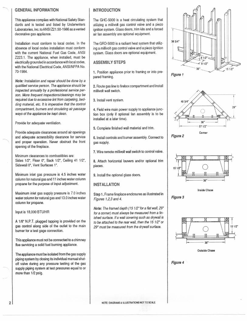
INTRODUCTION
The GHC-SOOOis a heat circulating system that
utilizing a miUivok gas control valve and a piezo
ignition system. Glass doors, trim kits and a forced
air fan assembly are optional equipment.
The GRD-SOOOis a radiant heat system that utiliz-
ing a millivoh gas control valve and a piezo ignition
system. Glass doors are optional equ~ment.
ASSEMBLYSTEPS
1.Position appliance prior to framing or into pre-
pared framing.
2.Route gas line to firebox compartment and installm~livoh waD switch.
3. Install vent system.
4. Field wire main power supply to appliance junc-
tion box (only if optional fan assembly is to be
installed aI a later time).
5. Complete finished wall malerial and trim.
6. Install controls and burner assembly. Connect to
gas supply.
7. Wife remote millivolt wall switch to control valve.
8. Attach horizontal louvers andlor optional \rim
pieces.
9. Install the optional glass doors.
INSTALLATION
Step1. Frame fireplace endosures as illustrated in
Rgures1,2,3and4.
Note:Theframeddepth(15112"for8 flatwall,29"for8corner)mustalwaysbemeasuredfroma fin-ishedsurface.Ifa wallcoveringsuchas drywallistobeattachedtotherearwall,thenthe15112"or29"mustbemeasuredfromthedrywallsurface.
NOTE:DIAGRAMS& illUSTRATIONS NOTTO SCAlE
~
r29"
i
~
Comer
FIgure2
36"
Inside Chase
FIgure 3
mt 36" I
Outside Chase
FIgure4

~
Step2.Routea112"NPTbiackirongasline8112"abovethefloorsurface(iffireplacewillberestingonthefloor)and8112"behindthefaceat theroughframing(Figure5).
~81fl'
Figure5
Note:Itisprefe"edtoroutethegaslineontherightsideofthefireplace,however,thegaslinemayberoutedtoeitherside.Thisgaslineshouldextendatleast2" intothecontrolcompartment(FIgure6).
~
jX'JL~~FIgure6
Step 3.Positiontheapplianceintopreparedfram-ing,naifingwith6dnailsthroughthenailingftangeholes.
Not,: Thenailingflangeandtheareadirectlybe-hindthenailingflangeareex9l1lptfromtheclear-ancesdescn'bedontheclearancelabel.
Step4. Installtheremotewallswitchinaconven-ientlocationandroutethe 18gagemilivot wirethroughtheoppositegaslineaccessholeintothecontrolcompartment.Atleast15"ofwireisrequiredinthecontrolcompartment.
Connecta 5"typeB-ventsystemto thefireplaceflueoutercoUarwithtwo (2)No.8 sheetmetalscrewsandinstalltheremainderofthistypeB-ventto the outside.Minimumheightof the ventandfireplaceshouldbe12feel.
LYBTYpe Vlnt
8-.FlulCo"arAssembly" .
FlUIOIII
11II" "
Collar " "".."
FIgure7
Note:RefertotheventmanufacturersinstaHationinstructionsforvariationsofventingtechniques.Ifcommonventingofseveralunitsiscontemplated,itshouldbediscussedwithanarchitectandthelocalBuildingDepartment.
Step6.11anoptionalforcedairfanistobeinstallednoworatsometimeinthefuture,thefireplacemustbeconnectedtothemainpowersupplyatthistime.Routea3 wire120V OOHzpowersupplylinethroughawallswitchandtothejunctionbox(locatedinthelowerrightsideofthefU'epIace)andground.RefertoFIgure8andtheinstallationinstructionspackedwiththeFAK-1500forcedai' ki.
LEGEND NDTES,
Step7.Completefinishedwallmaterialandtrim.
Step8.Thelogs,burnerandcontroltrayassemblyarepackedseparately.Whenreadyforfinalhook-up,positionthecontroltrayandburnerassemblyintothefireboxchamberbehindthefrontledge.
Step9.Attacha318"flexconnector(12"length;24"lengthifgassupplyline is installedonthe leftside)with a shutoff valve and a 318"adapter to the 112"
gas supplystub,usinga wrenchandp~ jointcompound.TIghtenscrewssecurely(Figure9).
112"ShutOffValve(OnPos~ion)
FIgure 9
Note: Donotdamageor kinkthe flex connector.
Step 10. Removethe 318"adapter fittingfromtheflex connectorand attach the adapter to the gascontrolvalveusinga wrenchand ~ jointcom-pound. Tighten securely(Figure10).
Step 11. Carefullybend and shape the flex gasconnector so that a connection can be made to the
adapterjust mountedonthegasvalve.Cautionshouki be used so as not to kink the gas connection
(FtgUf8 10).
W' Adlpllr
G. VII.
FIgure10
No,.: Check lor gas leaks with SOIipand watersoWon. DONOTUSEOPENFLAMEFORLEAKTESTING.
3
- U.. 1 "A', 01Th. D", W", A. S",., ,"d WIh." A.."", M." ..
"_d.hM."..'ep',,"WhhT,peAWMIOS.C A we. D'E,."...",.
2 M ,. Th..mOlyD d"""'_d.
,. 12DY" N..lou Th" , Am,..
",M""
M""~,,
12DY
~---,I,I
~ Ii""""'"l ~A" , ...
~cnnl~';:L T"'.....,: :,Ce,..
BIle, :D';Oti-:."i."""-- --- hm.J WoO"",Lnu
~f -~~~~:::::---~~~:::::::}:r.
FI..-"'d." ... - 'oc:1WyS......no-. ... S...",
(F.n WiringO;.g""'1
FIgure8
NOTE: DlAGlAMS' LlUSTRAllONS NOT TO SCAlE

r--Aftergas line installation is complete, use insulation
(not provided) to pack space where gas line pene-
trates the appliance. Pack insulation tightly from
outside the appliance to completely seal this space.
Step12.RemoteMIllivoltWallSwitchWiring.Attach one wire !rom the remote miUivolt wall switch
to the "TH" terminal on the gas control valve.Conned the other wire from the remote millivok wall
swftch to "TH TP" terminal at the gas control valve
(Figure11).
r ~-IIIIIIIIIIIIII
,
;:~,-I -I~::I:
II~
r~:mo~~tfj-+-[2GasVllve
To Remote Mllivol
Wall SwItch
Rgure11
CAUTION:DO NOT WIRE REMOTEWALLr'~, SWITCHTOAMAINPOWERSUPPLY.
Figure12
Figure134
HROIZONTALTRIMINSTALLATION
On the GHC Model, remove the four (4) black
louvers and the two (2) antique brass cover pieces
from the protective container and fasten onto the
face ofthe fireplace. The louver str~ snap onto the
louver pegs wnhoutthe need fortools. T 0 assemble
the louver str.,s, tilt the str., on top of the pegs and
snap lower edge to lock in place. The antique brass
cover pieces are mounted over the support bars
directly over and below the fireplace opening. They
also snap into place. Keep the locking dimples on
the bottom side of the covers when installing.
FLAMECOLORIZATIONDEVICES
The burner assembly is equ.,ped with a specialflame enhancement rod located between the lower
logs and a mineral fiber llame enhancement strip
across from the (lower) burner parts. These devices
colorize the gas flame and produce the "embereffect".
In normal operation, these devices will provide
many hours ofsatisfadory performance. Overtime,
the orange color wUldiminish in intensity and it will
be necessary to purchase a replacement rod and/or mineral fiber flame enhancement device. These
devices are available at nominal charge from your
local distributor/dealer or directly form Superior.
Flam. Enh8nctm.nt Rod
LogSetAgainstBackWaft
HIGHELEVATIONDERATING
Wheninstallingthesefireplacesabove4,000feellevel, n is recommended that the fireplace bumerbe
derated by changing the existing orifice to a smaller
one. Order and install appropriate high altnude
orificekit(Figure15). .
i~,j1...,
~148 Natural
158 Propane
(UseWhenDeratingBurner)
Rgure15
ACCESSORIESOptionalFanKIt
If the optional Ian kit, Model FAK-1500 is to beinstalled on the GHC-SOOONor GHC-SOOOLgas
fireplace,refertotheinstallaiton instrudions packed
wnh the fan assembly. The GHC-5000NandGHC-SOOOLgas fireplacehas beenprewiredat the fac-
tory to accept the forced air kit at some later time.
The firepalce, must, however, be connected to
main powersupplyattime of installation if the FAK-1500 forced air kit is to be instaUed later.
HorizontalTrimInstallation
There are three optional horizontal trim kits, Models
35HTK-SPS, HTK-PB and HTK-AB and two 0p-tional vertical trim kits, Models VTK-ABR and VTK-
GOEavailablefor usew~hthe GHC-SOOOgasfireplace.Referto thespecificinstallationinstruc-tionspackedwnh eachtrimkit lor theirproperusage.
OptionalGlassDoors
Several models of optional glass doors are avail-
able for installation on these gas fireplaces. Use
glass door Models 35G-PB, 33BF-AB, 33GOD-AS,33GBF-PB, 33GBF-SPB, 33GBFT-SPB, 33GBF-
ABR and 35GT-SPS wnh Model GHC-SOOON,L.
ForModelGRD-SOOON,L gas fireplaces,useglassdoor Models 33R-PB, 33BF-AB, 33GOD-AB,
33GBF-SPB, 33GBFT-SPB, 33GBF-ABR and33GBF-PB. Refer to the specific installation in-
structions packed w~h each glass door assemblyfor installation details.
Figure14
COLDCLIMATEINSULATION
If you live in a cold climate, seal all cracks around
your fireplace with non-combustible material andwherever cold air could enter the room. It is espe-
cially importantto insulate outside chase cav~ybetween studs and under floor on which rests, if
floor is above ground level.
Surround material must be caulked where n meets
the black metal facing of the fireplace to avoid airintrusion. Use non-combustible caulking material
onlyonfireplacefacingtoseal.
Do nol place insulation materials in the 1"gas vent
system clearance space.
NOTE:DIAGRAMS&LlUSTRA11ONSNOTTOSCALE

~
GLASSDOOROPERATINGPRECAUTIONSANDINSTRUCTIONS
.Keep wire mesh screens closed during fireplaceuse.
.Never clean glass when doors are hot. Avoid over-
spray of cleaner on brass pieces.
. Glass and metal frames get hot. Use only thewooden handles to open and close doors.
CAUTION:THEFIREPLACESHOULDONLYBEOPERATEDWITHTHE GLASS DOORSFULLYOPENORFULLY CLOSED.
-$-
Figure16
Bi.FoldGlass Doors
-$-~-T"~"'-"'--1 ' '---'
AIl-Glassl'M'And Twin-Pan.
GlassDoors
Figure17
FIREPLACESPECIFICATIONSGHC.5000N,L
~ 273/4"
~ 357~'
!41/4"
~II
TopFigure18
331/4" I341'rt'
UI
21"I
1112"
-'-~.-
Rgure19
PJ-i ! -~4F~_.
8E . ilt D' ~12"
L 7~~ i 10" I'6"~lilrt,T ~16"-.J
Ilrt'Left Right
Rgure20Front
FIREPLACESPECIFICATIONSGRD-SOOON,L
6112"
l;L
Figure 22
357~'
331/4"-
.-I
I,
I38314"
!
lkP'f~15,,-J
Right
5
2'"I
Front LeftRgur.23
NOTE:DIAGRAMS& IlLUSTRAnoNS NOTTOSCAlE

~
FINISHEDWALLDETAILS
" isbesttoframeyourfireplaceafter~ispositioned.Framewith2 x 4's or heavierlumber.Frameinaccordancew~hlocalprevailingbuildingcodes.
Note: Theheadermayrestonthetopmetalspac-ersbut mustnot be notchedto fit aroundthem.
Toinstallthefireplacelacingflushwiththefinishedwallpos~ionframeworktoaccommodatethethick-ness01thelinishedwall(Figure24, AandB).
Surroundmaterialscanbeplacedaroundthelire-placefacingtoprovideaflushsurfacebetweenthesurroundmaterialsandthefireplacelacing(Figure24, C and0 ).
FinishedWill
~~,/
11" Mln. ,
LLGHC-5000N,L
It.GRD-5000N,L
Non-combulllbl, BW8I1CoV8ring
finished Will
""Min. '
LLGHC-5000N,L
C
FIgure 24
GRD-5000N, L
Non-combustlbl, DWallCovering
Itisnotnecessarytoinstallahearthextensionw~hthisgasappliance."a hearthextensionisused,donotblockthelowerlouveredareaoftheGHC-5OOO.Anyhearthextensionusedislorappearanceonlyandneednotconformtonormalspecifications.
Acombustiblemantelshellprojectingamaximum018' Iromthewallmaybe installeda minimumdistance0111'abovethe GHC-5OOOandGRD-5000fireplaceopening(Figure25).
6
GRD-5000 Or GHC-5000
Figure25
OPERATION
Tooperatetheappliance,relerto thelightingin-structionslocatedontheback01theIrontcoverassembly.
Yourappliancecontrolsystemisamillivotttype.Itconsists01a pilotbumer,piezoign~ion,a gascontrolvalveandanONIOFFsw~ch.
Toobtainproperoperation,~isimperativethaithepilot and mainbumerflamecharacteristicsaresteady,notliltingor floating,andbebluein color(Figure26 ).
Note: Forpropaneuse,airshuttermustbeopen1/4inch(Figure30).
Naturel Of Porpana G.. Burntr
FIgure 26
Approximatelythetop3/8' at thepilotgenerator(thermopile)shouldbeengulfedinthepilotllame(Figure27 ).
Pilot Gtn8f8lor
(TherlllOpile)
PiezoIgnitor
Theairshuttersontheventuritubehavebeensetattheproperpos~ionatthefactoryforbothnaturalandpropanegasunits.Theairshutterfornaturalgashasbeensetinafullopenposition(Figures28and29 ).
ManKold
8~~.VenturiTube
NaturelG..
FIgure28
AIrShutter
1l0~\~
I~~ ~3J'8"
Naturel Gas Top View
Figure29
Theairshutterforpropanehasbeensetinthehalfopen, or 1/4' opening(Figures30 and 31).
""'~ DO"~AirShutt'r
/ J~~ ..-Venturi Tube
Propane Gas
Figure30
~lJ t:.POrpBne Gas Top VieW
Figure31
Figure277J
NOTE:DIAGRAMS&IlLUS1RATIONSNOTTOSCAlE

,, ,\
Anyvariationattheseairshuttersmayresultinanerraticflameand/orthepossibilityofsooting,distin-guishedbyabrightyellowflame.Anyadjustmentstotheairshutterdifferentfromthatdescribedabovecouldcausetheburnerassemblyto malfunctionandcouldvoidthewarranty.
OPERATIONGUIDELINESANDMAINTENANCEINSTRUCTIONS
1. Uponcompletingyourgaslineconnection,asmallamountofairwillbeinthelines.Whenfirstlightingtheappliance,~willtakeafewminutesforthe linesto purgethemselvesof this air. Oncepurgingiscomplete,thepilotandburnerwillfightandoperateasindicatedintheinstructionmanual.Subsequentlightingsof theappliancewillnotre-quiresuchpurging.
2.When~tforthefirsttime,theappfiancewiDem~aslightodorforanhourortwo.Thisisduetothe"curing"ofthelogsand"burn-offofinternalpaintsandlubricantsusedinthemanufacturingprocess.
3. Keepcontrolcompartment,logs,burnersandareasurroundingthelogscleanbyvacuumingorbrushingatleasttwiceayear.Donotvacuumthe
/"- mineralwoollocatedin the frontof the burnerassembly.
CAUTION:THE LOGS CAN GET VERY HOT-HANDLEONLYWHENLOGSARECOOL
4.Alwaysturnoff gasto pilotbelorecleaning.Beforere-lighting,refertothelightinginstructions.
5. Theapplianceandventingsystemshouldbeinspectedbeforeuseor at leastannuallyby aqualifiedserviceperson.
6.Alwayskeeptheapplianceareadearandfreefromcombustiblematerials,gasolineandotherflammableliquids.
7.Neverobstructtheflowofventilationair.Keepthefrontof the appliancedearof all obstadesandmaterials.
WARNING:CHILDRENAND ADULTSSHOULDBE ALERTED TO THE HAZARDS OF HIGHSURFACETEMPERATUREANDSHOULDSTAYAWAYTO AVOIDBURNSOR CLOTHINGIGNI.TION.YOUNGCHILDRENSHOULDBE SUPER-VISEDWHENTHEY ARE IN THE SAME ROOM
~ . ASTHEAPPUANCE.
MAINTENANCE
IMPORTANT:Turnoffgasandelectricalpowerbeforeservicingappliance.It isrecommendedthatacompetentservicemanperformthesecheckupsatthebeginningofeachheatingseason.
In orderto properlycleanthe burnerand pilotassembly,removetheglassenclosure,the logsandexposetheburnerandpilotassembly.
CleaningBurnerAndPilot
Cleanallforeignmaterialsfromtopofburnerandfrombottompanelbelowburner.Checkto makesurethatburnerorificeisclean.
Visuallyinspectpilot.Brushorblowawayanydustor lint accumulations.If pilotorificeis plugged,disassemblymayberequiredto removeanyfor-eignmaterialfromorificeortubing.Whenapplianceis putbackin service,checkpilotflamepatternsw~hRgure27.
WARRANTY
Yourgasfireplaceiscoveredbyaoneyearlimnedwarranty.Youwitlfindacopyofthewarrantyinthismanual.Pleasereadthewarrantytobefamifiarwnhn'svaluablecoverageandfileRwRhothersyousaveforfuturereference.
MILLIVOLTCONTROLLIGHTINGINSTRUCTIONS
1.Turnremotewalls~ch to"Off".Tumgasvalveknobto "pilor,depressandturnto "011".Waitfiveminutes.
2.Turngasvalveknobto"pilot".
3. HoldindepressedposRionandlightpilotbytriggeringthesparkign~er(pushingredbutton)untilpilotlights.Continueholdingknobdepressedforapproximately1112minutesuntilpilotremainsInwhenknobisreleased.
4.Turngasvalveknobto"an".Tumremoteswnchto "On".Burnerwincomeon.
SHUTDOWNINSTRUCTIONS
1.Theburnermaybeturnedoffbyturningremotesw~ch"Off".Thepilotwill remainInfor returntonormalservice.
2. Forcompleteshutdown:Tumremotesw~ch.olr. Depressandturngasvalveknooto "Off'.
NO~:DIAGRAMS&illUSTRATIONSNOTTOSCAlE
PILOTBURNERADJUSTMENTS
1.Removepilot adjustmentcap on mainvalve.
2.Adjustpilotscrewtoprovideproperlysizedflame(Figure27 ).
3. Replacepilotadjustmentscrew.
TROUBLESHOOTING
WrthproperinstaJlationandmaintenance,yournewgasfireplaceshouldprovideyearsoftroublefreeservice.If youdoexperiencea problem,troubleshootingguidesareprovidedinthismanual.Theseguideswillassistyouoraqualifiedservicepersonin the diagnosisof problemsandthe correctiveactiontobetaken.
REPLACEMENTPARTS
Contactthefactoryforquestionsconcerningpricesandpoliciescoveringreplacementparts.Partswillbesh"pedatprevailingprices.Normally,allpartscanbeorderedthroughyourSuperiordistributorordealer.
Whenorderingrepairparts,alwaysgivethefollow-inginformation:
1.Themodelnumberoftheappliance
2.Thepartnumber
3.Thedesaiptionofthepart.
4.Theinstallationdateoftheappliance.
Ifyouhaveanyquestionsorproblems,contactyourlocaldistributorldealeror:
Superior FIreplace Company4325Artesla Avenue
FuHerton,CA 92633
(714) 521-7302
7

REPLACEMENTPARTSLIST.~
ROBERTSHAWCONTROLS
8 *Note:Item21 intendedforhighaltitudeinstallation.Item23includesitems14and22 inasinglekit.
GHC.SOOON GRD.SOOON
GHC.SOOOL GRD.SOOOL
NO. DESCRIPTION PARTNO. CTY PARTNO. CTY
1 GasFireplaceAssembly 024711 1 024712 1
2 Bar,Louver 024501 4 -
3 Bar,Top 024491 1 -
4 Trim,Upper/Lower 024151 2 -
5 Panel,Screen/Pull 090083 2 090083 2
6 Rod,Screen 011381 2 011381 2
7 Refractory,Bottom 024931 1 024931 1
8 FrontCoverAssy. 025831 1 025833 1
9 Log,Main 028121 1 028121 1
10 Log,TopRight 028141 1 028141 1
11 Log,TopLeft 028151 1 028151 1
12 Cover,ScreenRod 011351 1 011351 1
13 WallSwitchKit 025971 1 025971 1
14 FrontFlameEnhancementStrip 032631 1 032631 1
22 FlameColorizationRod 032351 1 032351 1
*23 FlameEnhancementKit 033711 1 033711 1
GHC.SOOON GHC.SOOOLGRD.SOOON GRD.SOOOL
NO. CONTROLDESCRIPTION PARTNO. CTY PARTNO. CTY
15 Valve,GasControl(#7000MVRLC) 009737 1 093771 1
16 Orifice,#46(natural),#56(propane) 092751 1 092752 1
17 Igniter,Mini 091301 1 091301 1
18 PilotGenerator(Thermopile-TP-75)094699 1 094699 1
19 PilotAssembly 093761 1 093762 1
20 BurnerAssembly 024981 1 024981 1
*21 HighAltitudeOrificeKit 027961 1 027962 1

c._.
iI.°1 ~00
13
NOTE:DIAGRAMS&ilLUSTRATIONSNOTTOSCAlE
~
GHC-5000N,L
0
GRD-5000N,L
9

~
TROUBLESHOOTINGTHEELECTRICPIEZOIGNITORANDGASCONTROLSYSTEM
MODELSGHC-5000N,GHC-5000L,GRD-5000N,GRD-5000L
Note:Beforetroubleshootingtheeleetriepiezoignitorsystem,besureexternalgasshutoffvalve,locatedat thegassupplyinlet,isin the"ON"position.
~
10 NOTE:DIAGRAMS&ilLUSTRATIONSNOTTOSCAlE
SYMPTOM POSSIBLECAUSES CORRECTIVEACTION
1.Sparkignor willnotlightpilotafter A.Defectiveignor 1.Checkforsparkatelectrodeandpilot;ifnosparkrepeatedtriggeringof redbutton. (nosparkatelectrode). andelectrodewireisproperlyconnected,replace
theignor.
B.Defectiveormisalignedelectrodeatpilot 1.Usinga match,lightpilot.If pilotlights,tumoff(Sparkatelectrode). pilotandtriggertheredbuttonagain.Ifpilotlightsan
impropergasmixturecausedthebadlightingandalongerpurgeperiodisrecommended.Ifpilotwillnotlight- checkgapatelectrodeandpilot-shouldbe1/8inchtohaveastrongspark.IfOK,replacepilotassembly(Figure27).
2.PilotwillnotstayI aftercarefullyfollowing A.Defectivepilotgenerator(thermopile)or 1.Checkpilotflame.1tmustimpingeonpilotgen-lightinginstructions. remotewallswitchwiring. erator(Figure27). Cleanand/oradjustpilotfor
maximumflameimpingementongenerator.
2.Besurewireconnectionsfromgeneratoratgasvalveterminalsare tight andgeneratoris fullyinsertedintopitotbracket.
3.Oneofthewallswitchwiresmaybegrounded.Removewallsch wiresfromvalveterminals.Ifpilotnowstaysm,tracewallswch wiresforaground.Maybegroundedtofumaceorgassupply.
4.Checkpilotgeneratorwh miltivohmeter.Takereadingatgeneratorterminalsofgasvalve.Shouldread325miltivoltsminimumwhileholdingvalveknobdepressedin pilotposion andwallswitch"OFF".Replacefauhygeneratorifreadingisbelowspecifiedminimum.
B.Defectiveautomaticvalveoperator. 1.Turnknobto "ON",placewallswitchto "ON"mlivoltmetershouldreadgreaterthan100MV.IfthereadingisOKandtheburnerdoesnotcomeon,replacethegasvalve.
3.Pot burning,nogastoburJlftr,valveknob A.Wallswitchorwiresdefective. 1.Checkwallswitchandwiresforproperconnec-"ON",wallswitch"ON". tions.Jumpwiresfor properconnections.Place
jumperwire acrossterminalsat wallsch. Ifburnercomeson,replacedefectivewaDswitch.IfOK,placejumperwiresacrosswallsch wiresatgasvalve.Ifburnercomeson,wiresaredefectiveorconnectionsarebad.
B.Pot generatormaynotbegenerating 1.Re-checkSymptom#2.sufficientmivohage.
C.Pluggedburnerorifice. 1.Checkburnerorificeforblockag9andremove.
4.Frequentpilot outageproblem. A.Pilotflamemaybetooloworblowing(high) 1. Clean/adjustpilotflametor maximumflamecausingthepilotsafetyto dropout. impingementonpilotgenerator(FIgUf927).