manual_tm-1040
TRANSCRIPT
TM-1040PROGRESSIVE SCANNING
HIGH RESOLUTION CAMERA
(REV. 3)
OPERATIONS &MAINTENANCE MANUAL
Jan. 1996
TM-1040PROGRESSIVE SCANNING
HIGH RESOLUTION CAMERA
PRELIMINARY(REV. 3)
OPERATIONS &MAINTENANCE MANUAL
Jan. 1996
TM-1040PROGRESSIVE SCANNING
HIGH RESOLUTION CAMERA
PRELIMINARY(REV. 3)
OPERATIONS &MAINTENANCE MANUAL
Jan. 1996
TM-1040PROGRESSIVE SCANNING
HIGH RESOLUTION CAMERA
(REV. 3)
OPERATIONS &MAINTENANCE MANUAL
Jan. 1996
Covered by U.S. Pat. # 6259478 B1

1.1 Features and Applications
The TM-1040 is a state-of-the-art CCD camera whichuses a 1 inch 1K x 1K progressive scan interlinetransfer CCD imager.This CCD camera offers outstanding compactness,high resolution, built-in frame memory, asynchronousreset and electronic shutter, digital output as well asanalog video and a number of technical innovations.The camera's various features allow for versatileapplications, such as high resolution image capturing,machine vision, computer graphics, gauging, avionics,microscopy, medical imaging, character and finepattern recognition, document reading and high endsurveillance.
Miniaturized and light weightAll PULNiX cameras are built with the same designprinciples: Solid state technology; miniaturization;application specific such as custom design, remoteimagers, special functions for various applicationneeds; robust design even for military applications.
ImagerThe TM-1040 uses a 1K x 1K progressive scaninterline transfer CCD. The reason of such CCD is,1. High resolution (1024 x 1024 active pixels)
For very high resolution and image quality.2. Square pixel (9.0 x 9.0 µm)
Precise dimensional measurement ability.3. High speed electronic shutter capability
High dynamic resolution of moving object andelectronic iris control.Eliminates a need of mechanical shutter.
4. Progressive scanEliminates interlace deterioration of image.Ease of computer interface.
5. High sensitivity and low noise at fast scanningCan drive faster than 20 MHz x 2 pixel clock rate. (40 MHz output clock)Excellent S/N ratio (>50 dB).Micro lens built-in.
Asynchronous resetThe TM-1040 can be reset with external reset pulse(VINIT).When VINIT is enabled at Async mode, thecamera keeps discharging from CCD and with VINITleading edge (negative going pulse), it resets theinternal timing and starts integrating the image for thepreset period of shutter timing and outputs the asyncshutter video.This feature is especially important to capture movingobjects at the precise location of the field of view suchas belt conveyer, fast event observation and still picturecapturing.
Frame memory and Digital outputThe TM-1040 has two sets of built-in frame grabberand frame memory.The 10 bit A/D converter provides 1024 gray levels withmaximized signal-to-noise ratio. The output can be realtime digital output or captured image (frozen picture).The digital output format is always progressive scan atthe rate of 30 frames / sec. and is RS-422 differentialoutput. Due to the speed limitation of CCD readout, itkeeps two horizontal channel outputs in two sets offrame memory at 20 MHz and combined the readoutinto 40 MHz single (10-bit) output.
Async image capturingThe TM-1040 captures async reset image and providescontinuous video output of the same image.It makes simpler for an ordinary frame grabber tocapture the async reset images.
IntegrationThe TM-1040 is capable of capturing high resolutionintegration images. The integration can last from 1/30sec to a few seconds. For uniform and low noiseintegration, PULNiX offers a peltier cooled CCD option.
Analog output (interlace)Since 1K x 1K cameras are no longer in TV format, thedisplay of the video signal is only achieved by using aframe grabber and computer or special monitor.The TM-1040 has a feature of analog display modewhich scans the frame memory read out into two fieldsper 30 Hz frame (60 field / sec). This way it convertsthe progressive scan into interlace 30 frame/secdisplay mode for RS-343 or RS-170 (switchable).Electrohome EVM900 or EVM1200 series monitors orequivalent B/W monitor can display 1000 by 1000 pixelcounts. Consult PULNiX for display monitor information.This output can be recorded by RS-343 equivalentvideo recorders or RS-170 standard recorders.Since the TM-1040 has two sets of frame memory inthe digital and analog processing, the output isindependent to each other. While the digital is 10-bitnon-interlace, the analog is 8-bit conversion interlaceoutput.
NOTE1. PLEASE ALLOW 10 SEC. DELAY BEFORE
RESTARTING THE CAMERA.
2. TM-1040 HAS A BUILT-IN MICRO LENSCCD.
1

2. SPECIFICATIONSImager
Imager 1" Progressive scan interline transfer CCDTotal pixels 1024 (H) x 1024 (V)Photosensitive pixels 1008 (H) x 1018 (V) 6 + 10 ob(H), 4 + 2 ob (V)Photosensitive area 9.1 (H) x 9.2 (V) mmPixel size 9.0 (H) x 9.0 (V) µmOutput sensitivity 12 µV/e-Micro lens Built-inBlemish Point defect Cluster Column
Class 0 No defect 0 0Class 1 <5 0 0Class 2 <10 <4 <2Class 3 <20 <8 <4
CameraScanning 1024 lines 30 Hz ( Dual channel output from CCD, single channel
output for read out)Sync Internal / External auto switch
HD / VD, 4.0 Vp-p impedance 4.7 KΩfHD = 31.50 KHzfVD = 30 Hz
Pixel clock 20.034 MHz, output clock 40.068 MHzTV resolution Analog :700 (H) x 800 (V)..RS-343 , 700 (H) x 350 (V)..RS-170
Digital: 1008 (H) x 1009 (V) pixel resolutionMinimum illumination 2.0 lux, f = 1.4 without IR cut filterS/N ratio 50 dB min. AGC = OffVideo output Analog 1.0 Vp-p composite video, 75 Ω , sync negative
Digital 10-bit RS-422 differential outputData clock = 40.068 MHz
Display mode video Analog only RS-343: fHD = 31.50 KHz, fVD = 60 Hz, InterlaceRS-170: fHD = 15.75 KHz, fVD = 60 Hz, InterlaceProgressive: fHD = 31.50KHz, fVD = 30 Hz, Non-interlace
AGC OffMGC Manual gain adjustable ( 6 dB to 28 dB )Gamma 1.0 Lens mount C-mount........1" lens formatPower requirement 12 V DC 600 mA (800 mA for driving RS-422)Operating temperature -10° C to 50° CVibration and shock Vibration: 7G (200Hz to 2000Hz), shock: 70GSize 51mm (H) x 67 (W)mm x 160mm (L) (2.01" x 2.64" x 6.30" )Weight 330 grams ( 11.6 oz )Power cable 12P-02Digital cable 30DG-02 (8-bit), 30DG-02-10/40 (10-bit)Power supply K25-12V or PD-12
2
Wave Length (nm)
TM-1001 SPECTRAL RESPONSE
300 400 500 600 700 800 900 10000
0.2
0.1
0.3
0.4
0.5
0.6
0.7
0.8
O.9
1.0
Rel
ativ
e S
ensi
tivity
1100
Peak quantum efficiency: 38%
TM-1001
TM-1000

TM-1040 1K X 1K HIGH RESOLUTION ASYNCHRONOUS RESET FULL FRAME SHUTTER CAMERA
The TM-1040 is designed to accommodate a high resolution, ON-LINE inspection reset mechanism with fullframe shutter. It takes external horizontal sync to lock the camera and VINIT pulse for resetting the cameraasynchronously.The shutter speed can be controlled by either an external double pulse or internal shutter speed control with a10-position dial switch on the back panel.
1. Discharge Principle of CCD1.1 Substrate Drain Shutter MechanismNormal operation requires the CCD chip to construct an individual potential well at each image cell. The potentialwells are separated from each other by a barrier. The barrier is sequentially removed to transfer the charge fromone cell to another by pixel clock. This is the basic principle of the CCD operation for charge transfer.The substrate drain vertically moves the charges. When excess potential is applied to substrate underneath eachcell, a potential barrier is pulled down to release the charge into the drain. This can happen to all the cellssimultaneously, whereas normal CCD shuttering is achieved with a horizontal charge shift to the drain area byinterline transferring or reverse transferring of the frame transfer chip.
1.2 Asynchronous shutterFor Async Shutter mode, set jumper W5 of bottom board open and provide external Hd for phase locking. Whenthe negative going reset pulse is applied, the camera will latch the falling edge to its next horizontal drive andreset vertical sync timing immediately. Therefore, the horizontal phase won't be interrupted. The TM-1040asynchronous camera outputs a full frame of shuttered video in progressive scanning format from a frame buffer.The frame buffer is updated upon receiving negative reset pulse. The same full frame image (two fields) is outputfrom interlace analog signal with one field of delay.
3
Surface
Photo cell potential distribution
CCD surface + Potential barrier
Si substrate
Charge drain to substrate
Vsub = normal mode
Vsub = shutter mode
VINIT
VD
SG (TRANSFER GATE)
DISCHARGE PULSES
VIDEO
SHUTTERVIDEO
SAME VIDEOFROM FRAME MEMORY
PROGRESSIVE OUTPUT
VIDEO
SHUTTERVIDEO
SAME VIDEO FROMFRAME MEMORY
INTERLACE OUTPUT
1 FIELD DELAYDUE TO FRAME MEMORY
ASYNC RESET
OLD VIDEOIN MEMORY
OLD VIDEOIN MEMORY
A1 A2 B1 B2
A1: Odd field from old reset
A2: Even field from new reset
B1: Odd field from reset
B2: Even field from new reset

2. Shutter Speed Control2.1 External pulse width control mode
For External Pulse Mode, set dial switch to "9". Apply a pulse width control VINIT signal, which can be generatedfrom an external event trigger, to the camera. Internal reset pulse will be latched to Hd and at 9th HD timing fromexternal pulse leading edge ( negative going edge ), CCD discharge pulse is generated to clear the images.The internal VINIT is generated at the following edge ( positive going edge ) of the external pulse and it resetsinternal timing including the video sync.The shutter speed is the same as the external pulse width but the integration delays 9H from the leading edge.For immediate reset option, please contact PULNiX.One frame of video output will start from the rising edge of the pulse width control for progressive format. The camera will output the same video from memory when VINIT is kept high (5V) and update the image uponreceiving next pulse. At async mode, with external pulse input high, the video output is disabled as the camerakeeps discharging CCD image and only provides black video.
2.2 Internal Fast reset mode
4
9H
XExternal
Double
pulse
Hd
Internal Vinit
Transfer Gate
Pulse
Discharge pulse
Composite
Video
Exposure Time9H X
External pulse
Hd
Internal Vinit
Transfer Gate
Pulse
Purge pulse (discharge)
Composite
Video
9H
Exposure Time
min. 2H
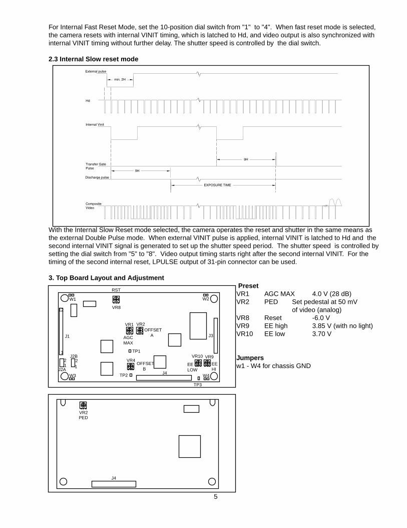
For Internal Fast Reset Mode, set the 10-position dial switch from "1" to "4". When fast reset mode is selected,the camera resets with internal VINIT timing, which is latched to Hd, and video output is also synchronized withinternal VINIT timing without further delay. The shutter speed is controlled by the dial switch.
2.3 Internal Slow reset mode
With the Internal Slow Reset mode selected, the camera operates the reset and shutter in the same means asthe external Double Pulse mode. When external VINIT pulse is applied, internal VINIT is latched to Hd and thesecond internal VINIT signal is generated to set up the shutter speed period. The shutter speed is controlled bysetting the dial switch from "5" to "8". Video output timing starts right after the second internal VINIT. For thetiming of the second internal reset, LPULSE output of 31-pin connector can be used.
3. Top Board Layout and Adjustment PresetVR1 AGC MAX 4.0 V (28 dB)VR2 PED Set pedestal at 50 mV
of video (analog)VR8 Reset -6.0 VVR9 EE high 3.85 V (with no light)VR10 EE low 3.70 V
Jumpersw1 - W4 for chassis GND
External pulse
Hd
Internal Vinit
Transfer Gate
Pulse
Discharge pulse
Composite
Video
9H
EXPOSURE TIME
9H
min. 2H
5
J1
12
12
1
VR8
VR1 VR2
VR4VR10 VR9
J3
J4
RST
AGCMAX
OFFSET A
EELOW
EEHI
OFFSET B
TP1
TP2
TP3
W1 W2
W3 W4
12
J2A
J2B
J4
VR2PED
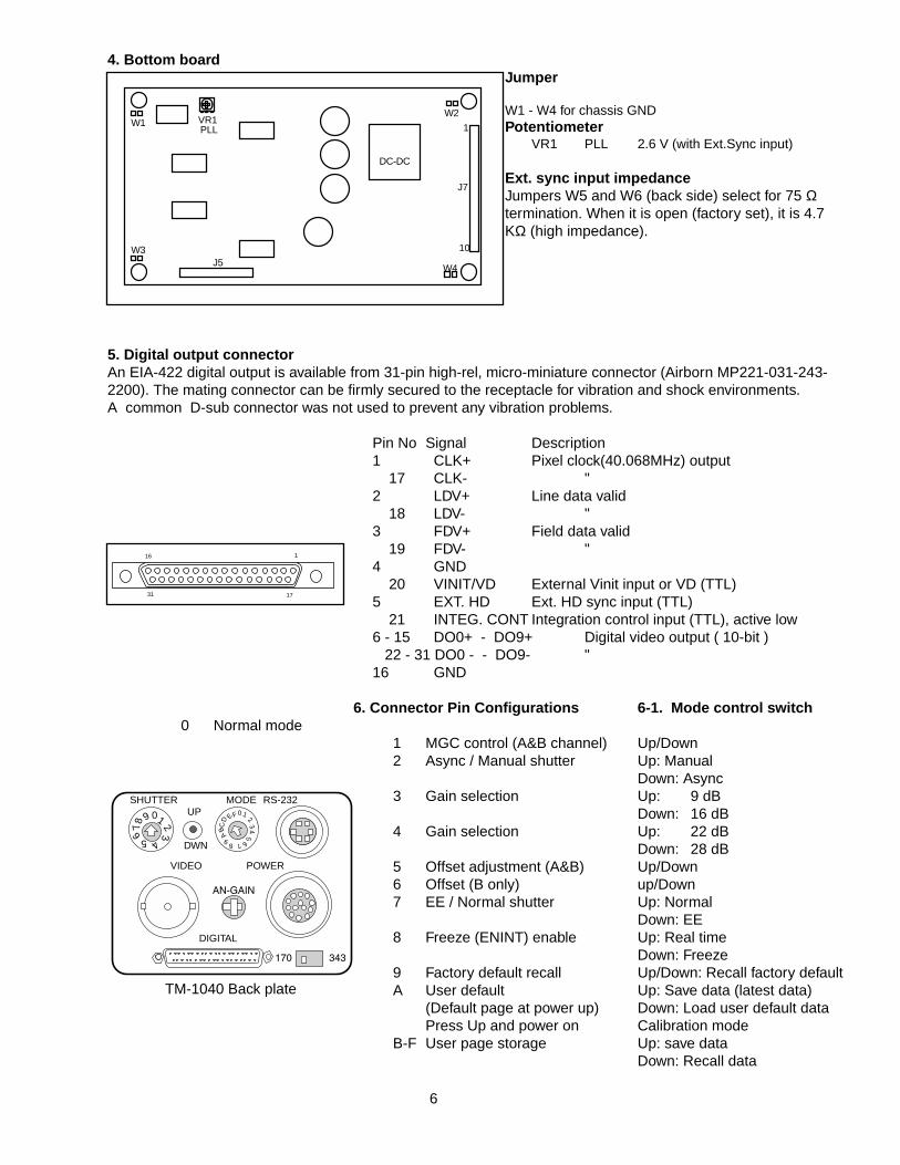
4. Bottom boardJumper
W1 - W4 for chassis GND Potentiometer
VR1 PLL 2.6 V (with Ext.Sync input)
Ext. sync input impedanceJumpers W5 and W6 (back side) select for 75 Ωtermination. When it is open (factory set), it is 4.7KΩ (high impedance).
5. Digital output connectorAn EIA-422 digital output is available from 31-pin high-rel, micro-miniature connector (Airborn MP221-031-243-2200). The mating connector can be firmly secured to the receptacle for vibration and shock environments.A common D-sub connector was not used to prevent any vibration problems.
Pin No Signal Description1 CLK+ Pixel clock(40.068MHz) output
17 CLK- "2 LDV+ Line data valid
18 LDV- "3 FDV+ Field data valid
19 FDV- "4 GND
20 VINIT/VD External Vinit input or VD (TTL)5 EXT. HD Ext. HD sync input (TTL)
21 INTEG. CONT Integration control input (TTL), active low6 - 15 DO0+ - DO9+ Digital video output ( 10-bit )
22 - 31 DO0 - - DO9- "16 GND
6. Connector Pin Configurations 6-1. Mode control switch0 Normal mode
1 MGC control (A&B channel) Up/Down2 Async / Manual shutter Up: Manual
Down: Async3 Gain selection Up: 9 dB
Down: 16 dB4 Gain selection Up: 22 dB
Down: 28 dB5 Offset adjustment (A&B) Up/Down6 Offset (B only) up/Down7 EE / Normal shutter Up: Normal
Down: EE8 Freeze (ENINT) enable Up: Real time
Down: Freeze9 Factory default recall Up/Down: Recall factory defaultA User default Up: Save data (latest data)
(Default page at power up) Down: Load user default dataPress Up and power on Calibration mode
B-F User page storage Up: save dataDown: Recall data
VR1PLL
J7
10
1W1
W3
W2
W4
DC-DC
J5
6
116
1731
012
34
5
6789
B
A
CED
F
SHUTTER MODEUP
DWN
VIDEO POWER
DIGITAL
RS-232
01 23456
78
9
170 343
AN-GAIN
TM-1040 Back plate
7
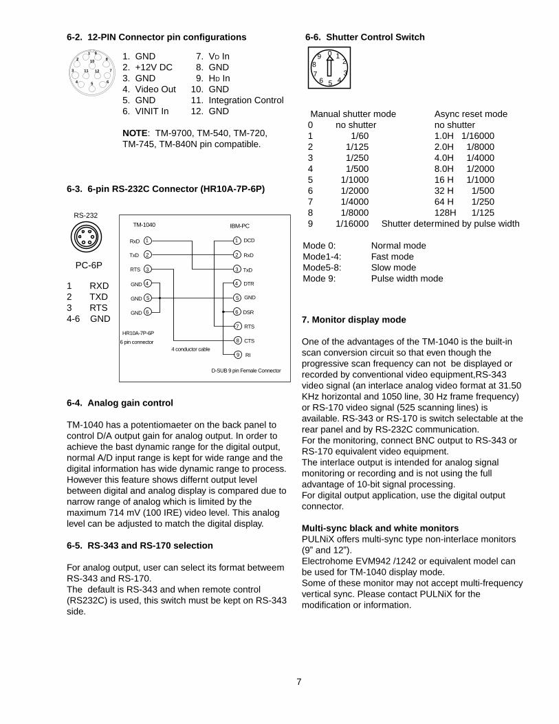
6-3. 6-pin RS-232C Connector (HR10A-7P-6P)
6-4. Analog gain control
TM-1040 has a potentiomaeter on the back panel tocontrol D/A output gain for analog output. In order toachieve the bast dynamic range for the digital output,normal A/D input range is kept for wide range and thedigital information has wide dynamic range to process.However this feature shows differnt output levelbetween digital and analog display is compared due tonarrow range of analog which is limited by themaximum 714 mV (100 IRE) video level. This analoglevel can be adjusted to match the digital display.
6-5. RS-343 and RS-170 selection
For analog output, user can select its format betweemRS-343 and RS-170.The default is RS-343 and when remote control(RS232C) is used, this switch must be kept on RS-343side.
7. Monitor display mode
One of the advantages of the TM-1040 is the built-inscan conversion circuit so that even though theprogressive scan frequency can not be displayed orrecorded by conventional video equipment,RS-343video signal (an interlace analog video format at 31.50KHz horizontal and 1050 line, 30 Hz frame frequency)or RS-170 video signal (525 scanning lines) isavailable. RS-343 or RS-170 is switch selectable at therear panel and by RS-232C communication.For the monitoring, connect BNC output to RS-343 orRS-170 equivalent video equipment.The interlace output is intended for analog signalmonitoring or recording and is not using the fulladvantage of 10-bit signal processing.For digital output application, use the digital outputconnector.
Multi-sync black and white monitorsPULNiX offers multi-sync type non-interlace monitors(9” and 12”).Electrohome EVM942 /1242 or equivalent model canbe used for TM-1040 display mode.Some of these monitor may not accept multi-frequencyvertical sync. Please contact PULNiX for themodification or information.
RS-232
PC-6P
6-2. 12-PIN Connector pin configurations
1
2
3
4
5
6
7
8
9
1
2
3
4
5
6
TM-1040 IBM-PC
RxD
TxD
RTS
GND
GND
GND
DCD
RxD
TxD
DTR
GND
DSR
RTS
CTS
RI
D-SUB 9 pin Female Connector
HR10A-7P-6P
6 pin connector4 conductor cable
1
2
3
4 5 6
9
8
711 12
10
6-6. Shutter Control Switch
Manual shutter mode Async reset mode0 no shutter no shutter1 1/60 1.0H 1/160002 1/125 2.0H 1/80003 1/250 4.0H 1/4000 4 1/500 8.0H 1/20005 1/1000 16 H 1/10006 1/2000 32 H 1/5007 1/4000 64 H 1/2508 1/8000 128H 1/125 9 1/16000 Shutter determined by pulse width
Mode 0: Normal modeMode1-4: Fast modeMode5-8: Slow modeMode 9: Pulse width mode
1. GND 7. VD In2. +12V DC 8. GND3. GND 9. HD In4. Video Out 10. GND5. GND 11. Integration Control6. VINIT In 12. GND
NOTE: TM-9700, TM-540, TM-720,TM-745, TM-840N pin compatible.
1 RXD2 TXD3 RTS4-6 GND
0 12
3456
78
9
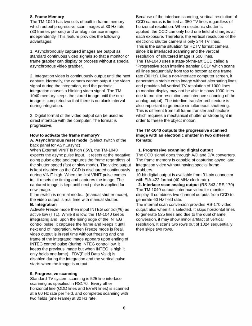
8. Frame MemoryThe TM-1040 has two sets of built-in frame memorywhich output progressive scan images at 30 Hz rate (30 frames per sec) and analog interlace imagesindependently. This feature provides the followingadvantages:
1. Asynchronously captured images are output asstandard continuous video signals so that a monitor orframe grabber can display or process without a specialasynchronous video grabber.
2. Integration video is continuously output until the nextcapture. Normally, the camera cannot output the videosignal during the integration, and the periodicintegration causes a blinking video signal. The TM-1040 memory keeps the stored image until the nextimage is completed so that there is no blank intervalduring integration.
3. Digital format of the video output can be used asdirect interface with the computer. The format isprogressive.
How to activate the frame memory?A. Asynchronous reset mode (Select switch of theback panel for ASY...async)When External VINIT is high ( 5V), the TM-1040expects the async pulse input. It resets at the negativegoing pulse edge and captures the frame regardless ofthe shutter speed (fast or slow mode). The video outputis kept disabled as the CCD is discharged continuouslyduring VINIT high. When the first VINIT pulse comesin, it resets the timing and captures the image. Thecaptured image is kept until next pulse is applied fornew image.If the switch is normal mode....(manual shutter mode),the video output is real time with manual shutter. B. IntegrationActivate Freeze mode then input INTEG control(#6) asactive low (TTL). While it is low, the TM-1040 keepsintegrating and, upon the rising edge of the INTEGcontrol pulse, it captures the frame and keeps it untilnext end of integration. When Freeze mode is Real,video output is in real time without freezing and oneframe of the integrated image appears upon ending ofINTEG control pulse (during INTEG control low, itkeeps the previous image but when INTEG is high itonly holds one fame). FDV(Field Data Valid) isdisabled during the integration and the vertical pulsestarts when the image is output.
9. Progressive scanningStandard TV system scanning is 525 line interlacescanning as specified in RS170. Every otherhorizontal line (ODD lines and EVEN lines) is scannedat a 60 Hz rate per field, and completes scanning withtwo fields (one Frame) at 30 Hz rate.
Because of the interlace scanning, vertical resolution ofCCD cameras is limited at 350 TV lines regardless ofhorizontal resolution. When electronic shutter isapplied, the CCD can only hold one field of charges ateach exposure. Therefore, the vertical resolution of theelectronic shutter camera is only 244 TV lines.This is the same situation for HDTV format camerasince it is interlaced scanning and the verticalresolution of shuttered image is 500 lines.The TM-1040 uses a state-of-the-art CCD called a"Progressive scan interline transfer CCD" which scansall lines sequentially from top to bottom at one framerate (30 Hz). Like a non-interlace computer screen, itgenerates a stable crisp image without alternating linesand provides full vertical TV resolution of 1000 lines(a monitor display may not be able to show 1000 linesdue to monitor resolution and interlace scanning of theanalog output). The interline transfer architecture isalso important to generate simultaneous shuttering.This is different from full frame transfer architecturewhich requires a mechanical shutter or strobe light inorder to freeze the object motion.
The TM-1040 outputs the progressive scannedimage with an electronic shutter in two differentformats:
1. Progressive scanning digital outputThe CCD signal goes through A/D and D/A converters.The frame memory is capable of capturing async andintegration video without having special framegrabbers.10-bit digital output is available from 31-pin connectorwith EIA-422 format (40 MHz clock rate).2. Interlace scan analog output (RS-343 / RS-170)
The TM-1040 outputs interlace video for monitordisplay. It combines two channel outputs from CCD togenerate 60 Hz field rate. The internal scan conversion provides RS-170 videooutput also when it is selected. It skips horizontal linesto generate 525 lines and due to the dual channelconversion, it may show minor artifact of verticalresolution. It scans two rows out of 1024 sequentiallythen skips two rows.
8

9. Mode control functions
-0. Normal modeCamera outputs real time normal video signal withoutelectronic shutter or asynchronous functions.
-1. MGC gain controlCDS amplifier gain of two channel can be controlledtogether by up/down switch. The minimum gain is 8 dBand the maximum gain is set internally (factory set is28 dB)
-2. Async / Manual shutter selectionThe electronic shutter mode is selected by up (manual)and down (async) switch.When it is in manual mode, the shutter speed isprogrammed by shutter speed switch and when asyncshutter is selected, the shutter timing works with VINIT(async reset pulse). If VINIT is kept high, it keepsdischarging CCD and when negative going pulsecomes in, it resets the timing and captures a imageand holds until next pulse comes. The async shutterspeed is also selected by the shutter selection switch.
-3 & -4. Gain selectionFixed specific gain is recalled by selecting 3 and 4 bypressing up/down switch up or down.
3 - up 9 dB, 3 - down 16 dB4 - up 22 dB, 4 - down 28 dB
-5. Offset adjustmentBlack level offset is adjustable by pressing up/downswitch. Two channels move together.
-6. Offset adjustmentOffset of B channel moves up/down in order tocalibrate black level banding (or flickering with interlaceoutput).
-7. EE/Normal ShutterAuto electronic shutter can be selected by pressingthe UP/DWN switch to DWN position.Normal shutter can be achieved by pressing UP/DWNswitch to UP position.
-8. Freeze (ENINT) enableThe internal frame buffer can freeze the image byselecting this function. When up/down switch is pushedup, it is real time image. When it is down, it freezes thefinal image. This freeze mode is also used forintegration control. At freeze mode, TM-1040 can beused to integrate (log exposure) by controlling INTEGcontrol input on 12-pin connector (pin #11). It keepsintegrating as long as the pin #11 is low and grab aimage upon the integration is over.
-9. Factory default recallThe factory default data is stored in page #9.
When an user needs the original calibration data,select #9 and press up/down switch to recall.This factory data can not be altered by user.
-A. User default data pageThe page #A is user default page which camera seesthis data to load at the power up unless user set aspecific page (B through F at power up).The last data can be stored in the page #A and it willbe kept for next operation. Note: Data cannot be savedunless save process is implemented.
-B through F. User data pagesBy selecting these pages, user can store and recallvarious data. Press up/down switch up to save andpress down to load the data.
10. Banding Calibration Mode (gain and offset)
Set MODE switch to #A while holding UP/DWN switch to UP position, and then power on the camera.(NOTE: In calibration mode, the last calibration data isautomatically saved in the page. To exit the calibration mode, turn off power once, thenpower up with the same page ...#A.)
1. MGC mode calibration (in calibration mode)1-1. Select mode switch #1 and adjust the gain levelfirst. 1-2. Then close lens to see offset uniformity.If the offset is to high or too low, select #5 to move upor down both channel together.1-3. Select #6 and adjust channel B only to obtain thebest balancing between channel A and channel B.1-4. Open lens and set the light intensity and adjust thechannel variance by selecting #2 and up/down switch.The channel B is calibrated to match channel A.1-5. Repeat 1-2 through 1-4 if necessary.1-6. Turn off power to exit calibration mode. then powerup again to see calibrated result.
2. Starting from specific gain selection (in calibrationmode)2-1. Select #3 or #4 up or down to chose the specificgain setting (9, 16, 22, 28 dB)2-2. Select #0 and press up/down switch up. Thisstores the gain memory to an RAM data and savesfollowing changes to the same memory pageautomatically.2-3. Adjust offset by closing lens and calibrate step 1-2through 1-3.2-4. Calibrate gain balance by following step 1-4. 2-5. Repeat 2-1 through 2-4 at different gain selection.All four gain setting with the individual variation can bestored.2-5. Turn off power and restart to see calibratedoperation.
9

11. Digital output pulsesDigital VideoDifferential line-driven, 10-bit parallel signal with EIA-422 format.100Ω output termination impedance.Output from 31-pin connector. The mating connector: Airborne MP211-031-113-4300Please consult digital cable information. eg. 50-1301-01, 30DG-02 (8-bit) or 30DG-02-10 (10-bit), 2m cable
Line Data ValidDifferential line-driven signal with EIA-422 format.It is active high (+ side is higher than - side) during the transfer of each line of data........Horizontal line read out.
Frame Data ValidDifferential line-driven signal with EIA-422 format. It is active high during the transfer of each frame data. Duringintegration, both LDV and FDV are kept low and restart upon the completion of integration.
Pixel clockDifferential line-driven signal with EIA-422 format. The frequency is 40.068 MHz (standard).Noti
10
1N = 24.96 µsec (40.068 MHz)
HD
1N
131NLDV
DIGITAL DATA
129N
264N
4N
1008N (Active Data)
6N (OB)
1N
1272N 1272N
131N
2544N
4N
264N 1008N (Active Data)
6N (OB)
VD
2LFDV
DIGITAL DATA
9L
41L 1009L (Active Data)
2L (OB)
1050L
4L 4L
2L 2L
1L = 1H / 2 = 31.75 µsec
9 ns
25 ns
DIGITAL DATA
PIXEL CLOCK
25 ns
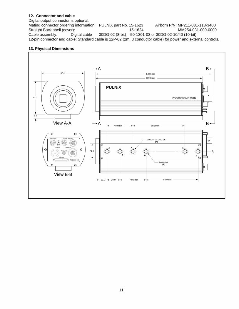
12. Connector and cableDigital output connector is optional.Mating connector ordering information: PULNiX part No. 15-1623 Airborn P/N: MP211-031-113-3400Straight Back shell (cover): 15-1624 MM254-031-000-0000Cable assembly: Digital cable 30DG-02 (8-bit) 50-1301-03 or 30DG-02-10/40 (10-bit) 12-pin connector and cable: Standard cable is 12P-02 (2m, 8 conductor cable) for power and external controls.
13. Physical Dimensions
11
169.0mm
178.5mm
PULNiX
PROGRESSIVE SCAN
40.0mm 80.0mm
40.0mm 80.0mm20.012.0
24.6 cL
A A A
B BB
3xO.25"-20 UNC-2B
3xM6x1.0
(A)
(B)
67.4
012
34
5
6789
B
A
CED
F
SHUTTER MODEUP
DWN
VIDEO POWER
DIGITAL
RS-232
51.2
7.0
01 23456
78
9
170 343
AN-GAIN
View A-A
View B-B
A
A
B
B

DIGITAL CABLE ASSEMBLY
30DG-02-40 P/N 50-1301-40 TM-1040 Full function cable (consult PULNiX for the frame grabber compatibility)
116
1731 TM-9700 31-pin connector
119
203737-pin D-SUB connector rear view
Pin Signal Cable
1 CLK+ OR 1RED2 LDV+ GRY 1RED3 FDV+ WHT 1RED4 GND YLW 1RED5 HD PINK1RED6 D0+ OR 2RED7 D1+ GRY 2RED8 D2+ WHT 2RED9 D3+ YLW 2RED10 D4+ PINK2RED11 D5+ OR 3RED12 D6+ GRY 3RED13 D7+ WHT 3RED14 D8+ YLW 3RED15 D9+ PINK3RED16 GND SHIELD
Pin Signal Cable
17 CLK- OR 1BLUE18 LDV- GRY 1BLUE19 FDV- WHT 1BLUE20 VINIT/VD YLW 1BLUE21 INTEG PINK1BLUE22 D0- OR 2BLUE23 D1- GRY 2BLUE24 D2- WHT 2BLUE25 D3- YLW 2BLUE26 D4- PINK2BLUE27 D5- OR 3BLUE28 D6- GRY 3BLUE29 D7- WHT 3BLUE30 D8- YLW 3BLUE31 D9- PINK3BLUE
Pin Signal Cable
1 CLK+ OR 1RED2 LDV+ GRY 1RED3 FDV+ WHT 1RED4 N/C5 N/C6 D0+ OR 2RED7 D1+ GRY 2RED8 D2+ WHT 2RED9 D3+ YLW 2RED10 D4+ PINK 2RED11 D5+ OR 3RED12 D6+ GRY 3RED13 D7+ WHT 3RED14 D8+ YLW 3RED15 D9+ PINK 3RED16 GND YLW 1RED17 VINIT YLW 1BLUE18 N/C19 N/C
Pin Signal Cable
20 CLK- OR 1BLUE21 LDV- GRY 1BLUE22 FDV- WHT 1BLUE23 N/C24 N/C25 D0- OR 2BLUE26 D1- GRY 2BLUE27 D2- WHT 2BLUE28 D3- YLW 2BLUE29 D4- PINK 2BLUE30 D5- OR 3BLUE31 D4- GRY 3BLUE32 D6- WHT 3BLUE33 D7- YLW 3BLUE34 D8- PINK 3BLUE35 GND SHIELD36 N/C37 INTEG PINK 1BLUE
TM-1040
TM-1040 PIN CONFIGURATIONS
37-PIN D-SUB CONNECTOR PIN CONFIGURATIONS
12
Note: TM-1040 digital output is 10-bit and some of frame grabber or a standard 37-DSUB connector cable maynot be able to support 10-bit at 40MHz. You can simply use 8-bit output with standard 30DG-02 cable or contactPULNiX for a special interface cable to the specific frame grabber.
14 TM-1040 RS-232C CONTROLThe TM-1040 can be controlled its built-inmicrocomputer chip (CPU) by external RS-232Cinterface. The internal CPU controls TM-1040operation mode and DSP parameter changes.(Contact PULNiX for the TM-1040 software disket)14-1. RS-232C communication default condition
Parity : NoneData : 8 bitSTOP : 2 bitBaud rate : 9600 bps
( If other communication condition is required, pleasecontact PULNiX.)
14-2. RS-232C commandThe TM-1040 command packet starts with STX (Startof Text = 02H) and then followed by Command Code(C.C. ....one alphabet) , Command option parameterand ETX (End of Text = 03H) to end.One packet is 8 bit ASCII code.When a packet is received by TM-1040 ( ETX:03H isdetected), it reads internal packet of the receiver buffer.If it is the correct packet then it processes theparameters based on the command. When the processis completed, it sends a completion signal (AK packet).If an error is detected, No-go signal (NK packet) is sentback and disregards the packet signal in the buffer.When NK packet is sent from TM-1040, the host mustcorrect the error and resend the packet.
Example: Executing shutter controlIn order to set EE mode, The C.C. packet is sent asfollows,
STX, “S”, “E”, ETX02H,53H,45H,03Hwhere “S”.....Shutter control command mode
“E”.....EE (auto-shutter) modeThe TM-1040 will send backSTX,ACK,ETX or STX,NAK,ETX02H,06H,03H 02H,15H,03H
14-3. Command FFunction: Analog output selection command“0” following “F” command is RS-170“1” following “F’ command is RS-343“2” following “F’ command is progressive scan
14.4 Command SFunction: Shutter control commandShutter mode selection and shutter speed setting.
14-4-1 Manual shutter mode STX,”SM”, ”0” -”9” or “S”, ETX02H,53H,4DH, 30H - 39H or 53H,03H
It enables manual shutter operation. Select “0” - “9”shutter speed. It over-rules the back panel setting.When “S” code is selected, the back panel shutterswitch is activated for the speed selection.
14-4-2 Async shutter modeSTX, “SA”,”0” - “9” or “S”,ETX
02H, 53H,41H, 30H - 39H, or 53H ,03HIt enables async shutter mode.
14-4-3 EE shutter modeSTX,”SE”, ETX02H, 53H, 45H, 03H
14-4-4 Direct shutter modeSTX, “SX”, “1A0”, ETX02H, 53H, 58H, 31H,41H,30H, 03H
It selects a mode for external shutter speed control.Hexadecimal shutter number (3 digit) follows “SX”command. (eg. “1A0” = 416H, shutter speed = (1050-416) = 634H = 20 msec...1/50 sec). It moves shutterdischarge pulse at every 1H (32 µsec.) period from 0 (no shutter) to 1049 H (=1/32,000 sec.).
14-5 Command MFunction: Changes memory mode betweenFreeze and free -run mode
Freeze mode: STX, “M”, “0”, ETX02H,4DH, 30H, 03H
Free-run mode: STX, “M”, “1”, ETX02H, 4DH, 31H, 03H
14-6. Command G
Function: A/D pre-amp gain controlFirst value next to “G” command is A channel, secondvalue is B channel.
STX, “G”, “FF”, “FF”, ETXFFH = gain 255
02H, 47H, 46H,46H, 46H,46H, 03H
STX, “G’, “12”, “10”, ETX02H, 47H, 31H, 32H, 31H, 30H, 03HChannel A = gain control value 18Channel B = gain control value 16
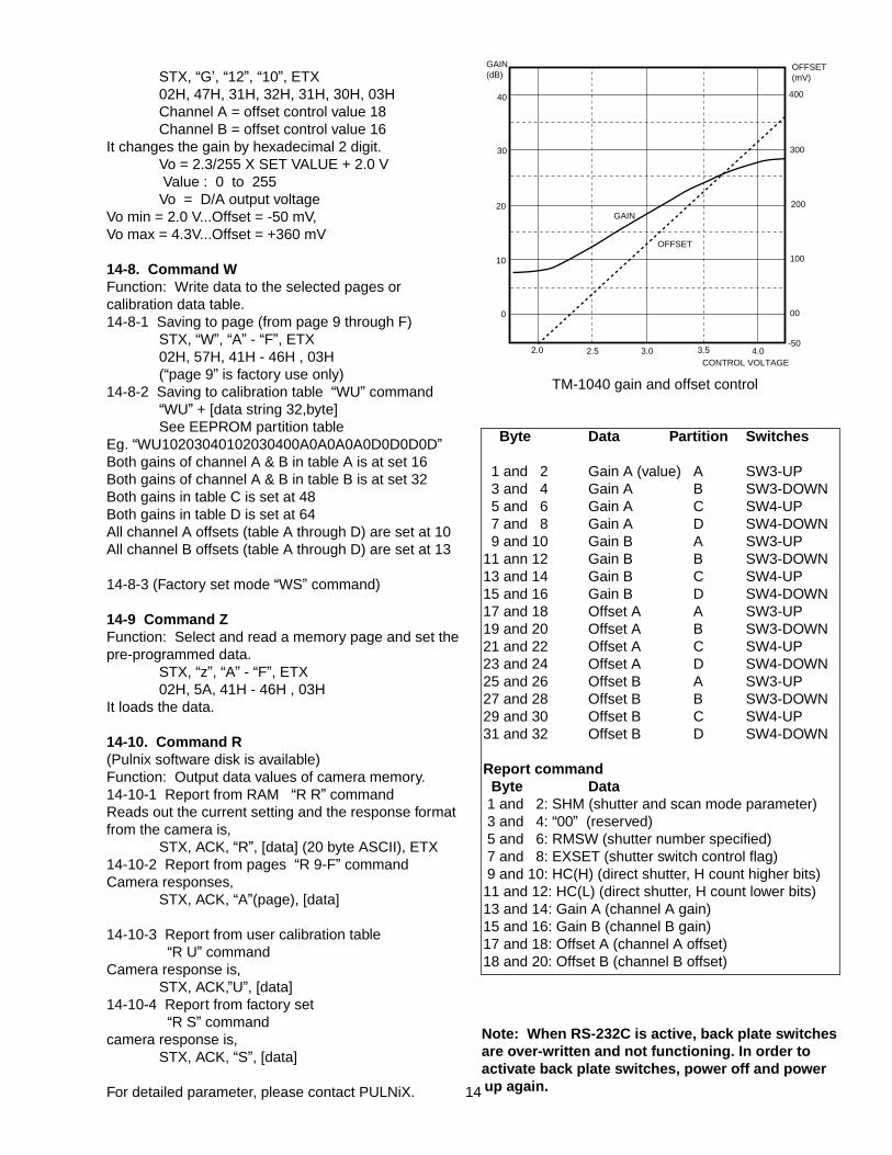
It changes the gain by hexadecimal 2 digit.VO = 2.3/255 X SET VALUE + 2.0 VValue : 0 to 255VO = D/A output voltage
(Vo min = 2.0 V...8 dB, V0 max = 4.3V...28 dB)
14-7. Command OFunction: A/D pre-amp offset controlFirst value next to “O” command is A channel, secondvalue is B channel.
STX, “G”, “00”, “00”, ETX00H = offset o
02H, 47H, 30H,30H, 30H,30H, 03H
13
STX, “G’, “12”, “10”, ETX02H, 47H, 31H, 32H, 31H, 30H, 03HChannel A = offset control value 18Channel B = offset control value 16
It changes the gain by hexadecimal 2 digit.Vo = 2.3/255 X SET VALUE + 2.0 VValue : 0 to 255Vo = D/A output voltage
Vo min = 2.0 V...Offset = -50 mV, Vo max = 4.3V...Offset = +360 mV
14-8. Command WFunction: Write data to the selected pages orcalibration data table.14-8-1 Saving to page (from page 9 through F)
STX, “W”, “A” - “F”, ETX02H, 57H, 41H - 46H , 03H(“page 9” is factory use only)
14-8-2 Saving to calibration table “WU” command“WU” + [data string 32,byte]See EEPROM partition table
Eg. “WU10203040102030400A0A0A0A0D0D0D0D”Both gains of channel A & B in table A is at set 16Both gains of channel A & B in table B is at set 32Both gains in table C is set at 48Both gains in table D is set at 64All channel A offsets (table A through D) are set at 10All channel B offsets (table A through D) are set at 13
14-8-3 (Factory set mode “WS” command)
14-9 Command ZFunction: Select and read a memory page and set thepre-programmed data.
STX, “z”, “A” - “F”, ETX02H, 5A, 41H - 46H , 03H
It loads the data.
14-10. Command R(Pulnix software disk is available)Function: Output data values of camera memory.14-10-1 Report from RAM “R R” commandReads out the current setting and the response formatfrom the camera is,
STX, ACK, “R”, [data] (20 byte ASCII), ETX14-10-2 Report from pages “R 9-F” commandCamera responses,
STX, ACK, “A”(page), [data]
14-10-3 Report from user calibration table“R U” command
Camera response is,STX, ACK,”U”, [data]
14-10-4 Report from factory set“R S” command
camera response is,STX, ACK, “S”, [data]
For detailed parameter, please contact PULNiX.
Note: When RS-232C is active, back plate switchesare over-written and not functioning. In order toactivate back plate switches, power off and powerup again.
2.0 2.5 3.0 3.5 4.0CONTROL VOLTAGE
GAIN(dB)
OFFSET(mV)
00
100
200
300
400
-50
0
10
20
40
30
GAIN
OFFSET
TM-1040 gain and offset control
Byte Data Partition Switches
1 and 2 Gain A (value) A SW3-UP3 and 4 Gain A B SW3-DOWN5 and 6 Gain A C SW4-UP7 and 8 Gain A D SW4-DOWN9 and 10 Gain B A SW3-UP
11 ann 12 Gain B B SW3-DOWN13 and 14 Gain B C SW4-UP15 and 16 Gain B D SW4-DOWN17 and 18 Offset A A SW3-UP19 and 20 Offset A B SW3-DOWN21 and 22 Offset A C SW4-UP23 and 24 Offset A D SW4-DOWN25 and 26 Offset B A SW3-UP27 and 28 Offset B B SW3-DOWN29 and 30 Offset B C SW4-UP31 and 32 Offset B D SW4-DOWN
Report commandByte Data1 and 2: SHM (shutter and scan mode parameter)3 and 4: “00” (reserved)5 and 6: RMSW (shutter number specified)7 and 8: EXSET (shutter switch control flag)9 and 10: HC(H) (direct shutter, H count higher bits)11 and 12: HC(L) (direct shutter, H count lower bits)13 and 14: Gain A (channel A gain)15 and 16: Gain B (channel B gain)17 and 18: Offset A (channel A offset)18 and 20: Offset B (channel B offset)
14

Notice
The material contained in this manual consists of information that is proprietary to Pulnix America, Inc. and mayonly be used by the purchasers of this product. Pulnix America, Inc. makes no warranty for the use of its productsand assumes no responsibility for any errors which may appear or for damages resulting from the use of theinformation contained herein. Pulnix America, Inc. reserves the right to make changes without notice.
Warranty
All our solid state cameras have a full three year warranty. If any such product proves defective during thiswarranty period. Pulnix America, Inc. will repair the defective product without charge for parts and labor or willprovide a replacement in exchange for the defective product. This warranty shall not apply to any damage, defector failure caused by improper use or inadequate maintenance and use.
Revised Printing: July, 1996
Pulnix America, Inc.
1330 Orleans DriveSunnyvale, CA 94089Tel: (408) 747-0300
(800) 445-5444Fax: (408) 747-0880