manuat pcao standard - besturingen.com e.pdf · manuat pcao standard ... highly-intelligent...
TRANSCRIPT

programmabie controüers
Manuat PCAO standardCompact-PLC with high inteHigence
Engiish edition 26/79 E2


Series PCA0
The compact
highly-intelligent
programmable controller
Four standard versions with up to 64 I + 0
4K user steps
Programmable according to ladder diagram, logic diagram, flow-chart orfunctional diagram as per DIN-standard.
Arithmetic instructions and security commands for permanent monitoringof the operation (watchdog and check sum).Easy beginning for learners but with big power reserve for the demandingPC-user.
01.03.1987 Setting price: sFr. 20.--


satapcWho uses the PCA0-manual?
We do not know how familiar you are with programmable controllers. Maybe youare a beginner or already an experienced PC-specialist.
This manual serves as a course, in order to give the beginner an easyintroduction to the world of programmable controllers. Read especially thechapters 1 to 5 carefully before you start to work and do not let yourselfbe confused with the diagrams in the chapters 6 and 7. These are not im-portant at the beginning if you have equipped yourself with the simulationand power supply unit PCA2.S05 (see chapter 5e).
In chapter 9 you will be gradually led up the staircase from A via B to C.For this, we use easy and clear examples, which can be collectively testedon your desk with the above-mentioned simulation unit.
If you do not know how to go on, please make use of the experience of ourspecialist in your vicinity or register for the next workshop.
We wish you a lot of fun with the versatile PCA0!
If you are a PC-specialist, you do not have to read all the information inchapter 9. In this case, concentrate on the instruction lists at the be-ginning of parts A, B and C. If you want to know more about these instruc-tions, refer to the elaborated "Basic Manual".
(LANHIS&GYR)

Eatapc PCA0-1
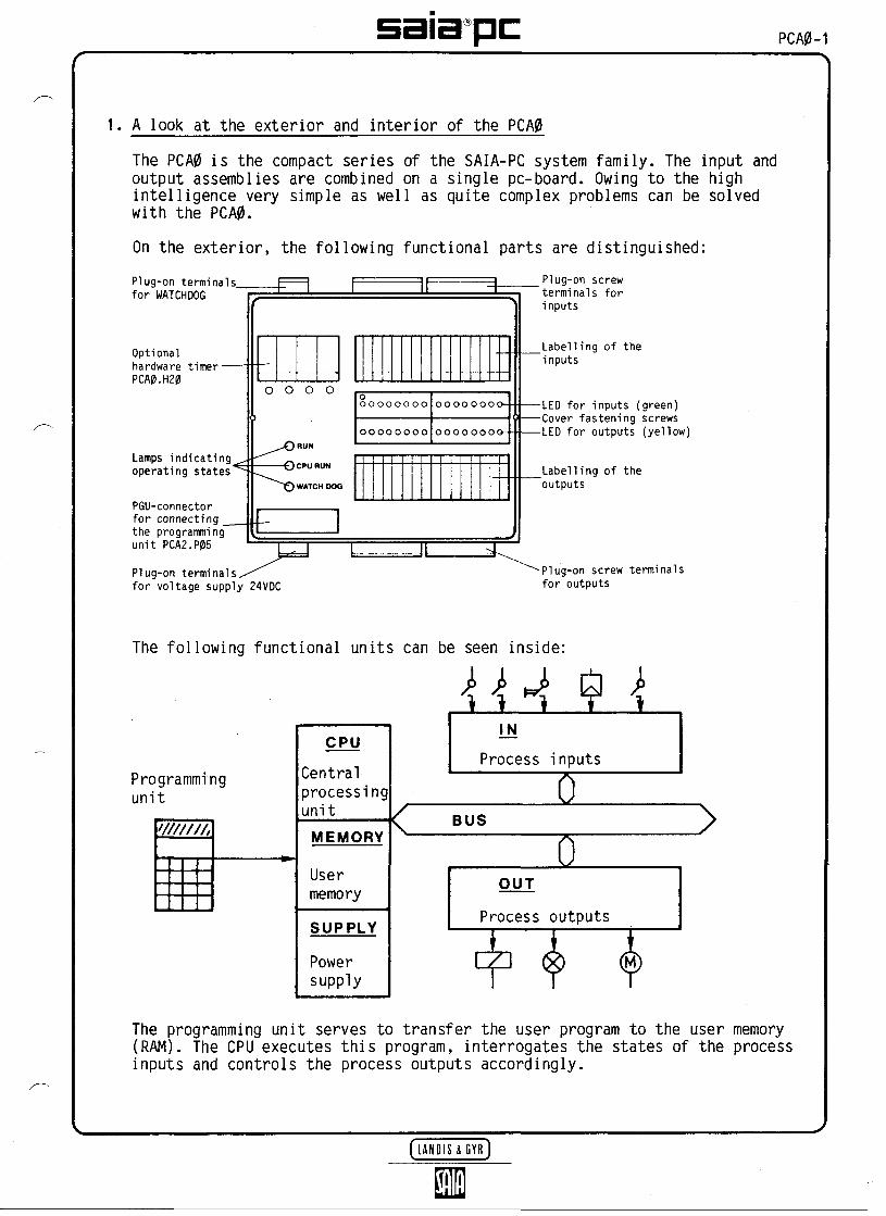
1. A look at the exterior and interior of the PCA0
The PCA0 is the compact series of the SAIA-PC system family. The input andoutput assemblies are combined on a single pc-board. Owing to the highintelligence very simple as well as quite complex problems can be solvedwith the PCA0.
On the exterior, the following functional parts are distinguished:Plug-on terminalsfor WATCHDOG
Optionalhardware timer-PCA0.H20
Lamps indicatingoperating states
PGU-connectorfor connecting _the programmingunit PCA2.P05
Plug-on terminals,for voltage supply 24VDC
o
,/^
o
O-OO
o o
RUN
CPU RUM
WATCH OO
Ooooooooo
oooooooo
oooooooo-
oooo oooo- -
Plug-on screwterminals forinputs
Labelling of theinputs
LED for inputs (green)Cover fastening screwsLED for outputs (yellow)
Labelling of theoutputs
* Plug-on screw terminalsfor outputs
The following functional units can be seen inside:
Programmingunit
CPU
CentralprocessingunitMEMORY
Usermemory
SUPPLY
Powersupply
Process inputs
BUS
OUT
Process outputs
The programming unit serves to transfer the user program to the user memory(RAM). The CPU executes this program, interrogates the states of the processinputs and controls the process outputs accordingly.

PCA0-2 saia pc2. Common technical data
Microprocessor system
Cycle time per user instruction(average)
Instruction set level (]H)
Number of parallel programs
Number of index registers
Number of subroutine levels
User memory
Volatile/non-volatile flags
Number of software counters and timers
Counting capacity
Time ranges (time base 0.1 or 0.01s)
Hardware timer PCA0.H20
Connection of peripherals
Operating modesIndicating lamps
Inputs(B90)
Relay outputs(A21)
Transistor outputs(B90)
Supply voltage
Ambient temperature
High noise immunity
8085-2
70 us
32 basic instructions + 20 additionalinstructions incl. arithmetic
16
16 (1 per parallel program)
3
4K program tines (s 8K Bytes)
477* + 235 = 712
64 addresses (C = 64, T = 32)
65'535
0.1 (0.01) to 6500 (650)s
4 time ranges 0.9/3.7/30/240S
via 25-pole PGU-connector
RUN, BREAK, STEP, MAN, PROG
LED for RUN/CPU RUN/WATCHDOGLED for I/O
galvanically connected, sourceor sink operation nominal +24VDCH = +19...+32VL = 0...+ 4VI = 10mA, 24VDC, tj = 9ms
galvanically isolated, normallyopen contactscontact rating 3A, 250VAC AC1
3A, 24VDC DC1
galvanically connected, positiveswitching 0.5mA...0.5A, 5...36VDC
24VDC +20%
0...+50°C
as per IEC 255-4/E5 class III,i.e. 2500V and IEC 801-4class III (2000V)
*) By inserting the jumper "NV", all flags and registers for timers andcounters are made non-volatile.

satapc PCA0-3
3. The four standard versions
3.1 With relay outputs
Type PCA0.M12R M4
16 I, 24VDC8 0, relay contact
max. 3A, 250VAC! — !
t t
ooo
[ 1
t _ !
] [ ]0...7)8...15
)2x81
ttt
,2x*40
<Re'tay
27...24J19...16) t t
Type PCA0.M14R M4
32 I, 24VDC16 0, relay contact
max. 3A, 250VAC
] )
[ !
ooo
1 1
[ ]
0...7
——— -^
59. ..56
) H !8...15J16...23
,4x81!t
^ ——— _f.-_-i
4x4O!
Re!ay51. ..48 }43. ..40
t ]24. ..31
----
35. ..32JE.
3.2 With transistor outputs
Type PCA0.M12T M4
20 I, 24VDC12 0, 0.5A/24VDC
Type PCA0.M14T M4
40 I, 24VDC25 0, 0.5A/24VDC
! t
! !
ooo
i !
! i,)P...7 8..
2x81
------- --^
8O 4O
Transi itor3l. ..24 23.
1. 15
— — .
41
.16
1 1
ooo
! 1
0... 7 's... 15i 16. ..23! li 4x81! i] ]
, 1' ,1 !]3x8Oil '
Transistor63. ..56 [55. ..48 [47. ..40
24. ..31
t — — — — *
81
39. ..32
Detailed information on the inputs/outputs see chapter 7.
Please note: If a certain number of units are ordered, we Mill supplyyou, too, with a custom-made version. Please contact ournearest selling agency.

PCA0-4 sata pc4. Important accessories
4.1 The hardware timer module PCA0.H20
3OGG
64 65 66
Fastening screw
Potentiometer for infinitelyvariable time setting
Selector switch for 4 ranges
G 0.1 ... 0.9s(D 0.4 ... 3.7sO 3.2 ... 30sO 25 ... 240s
-LED lights up if the timer is active(running down)
-Addresses of the hardware timers
-Connector to CPU pc-board
This module is an option and must be ordered separately. It allows easysetting of four time ranges in the RUN-mode independently of the program(e.g. for setting delay times).
The repetition accuracy is:
- under constant conditions 0.1% of the time range set- under extreme conditions 1% of the time range set
(T = 0...50°C, U = 24V +20%)
For waiting for a time to elapse, set at timer 64, use the followingsimple program:
REO 64SEO 64WIH 64
The corresponding LED lights up while the timer is running down.
Please do not forget that this module is only necessary, if the 32software timers included in every standard PCA0 do not suffice. Thesoftware timers can be modified in the range 0.01s to 6500s by theprogram or via 8 inputs by means of the BCD-switches in the RUN-mode(see example A8).

satapc PCA0-5
4.2 The user memory
Three different types of user memories with 4K (4096) user steps each areavailable:
- RAM-chip 8464 on socket, order no. 4*502*4718*0
This type of memory allows one to write, erase or overwrite a program asdesired with the hand-held programming unit P05. In case of a voltagefailure, the memory contents are stored in the CPU for approximately2 months thanks to the buffer battery. The program, however, cannot betransported, as it is lost when the RAM-chip is removed.
- Buffered RAM-memory module type PCA1.R95
Contrary to the RAM-chip, the program in this memory can be transported,as it is protected by an integrated electronic system and stored by alithium battery for approximately 8 years.
Programming with the hand-held programming unit P05.
- EPROM-chip 2764 on socket, order no. 4*502*4719*0
In an EPROM a program is reliably stored for more than a decade.However, the program cannot be entered directly into the EPROM withthe PCA0. For this, the following possibilities are offered (ask forthe special documentation):
a) with the EPROM-load module PCA2.P16b) with the universal programming unit PCA2.P21c) with the CPUs of the series PCA2 (M31 and M32)
Every EPROM can be erased with an appropriate UV-light source almost asoften as desired.
Depending on the user memory in use, the selection jumpers on the CPUmust be inserted (see also figure in chapter 5).
for R95 for EPROM 2764 for RAM 8464
2764 — Lo 27648464/R95 - ^2764/R?? - _.. 27648464 —<
Standardfactory setting
*) Position for write-protection
Please note: The jumpers should be repositioned only with the PCswitched off.
PCAP-6 satspc4.3 The programming units
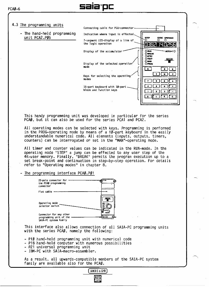
- The hand-held programmingunit PCA2.P05
Connecting cable for PGU-connector
Indication where input is effected
7-segment LED-display of a line ofthe logic operation
Display of the accumulator
Display of the selected operationmode
Keys for selecting the operatingmodes
16-part keyboard with 10-partblock and function keys
This handy programming unit was developed in particular for the seriesPCA0, but it can also be used for the series PCA1 and PCA2.
All operating modes can be selected with keys. Programming is performedin the PROG-operating mode by means of a 10-part keyboard in the easilyunderstandable numerical code. All elements (inputs, outputs, timers,counters) can be interrogated or set in the "MAN"-operating mode.
All timer and counter values can be indicated in the RUN-mode. In theoperating mode "STEP" a jump can be effected to any user step of the4K-user memory. Finally, "BREAK" permits the program execution up to aset break-point and continuation in step-by-step operation. For detailsrefer to "Operating modes" in chapter 8.
- The programming interface PCA0.P0125-pole connector forthe PCA0 programmingconnector
Flat cable
Operating modeselector switch
Connector for any otherprogramming unit of theSAIA-PC system family
This interface also allows connection of all SAIA-PC programming unitswith the series PCA0, namely the following:
- P10 hand-held programming unit with numerical code- P18 hand-held computer with numerous possibilities- P21 universal programming unit- IBM-PC with SAIA-macro-assembler.
As a result, all upwards-compatible members of the SAIA-PC systemfamily are available also for the PCA0.

PCA0-7
5. Brief instructions for operating the PCA0
Connection terminalsfor WATCHDOG PCA0.M12
PCAO.M14
Function jumpers
User memory
Operating mode indicatinglamps
PGU-connector for'programmingunit
Connection terminals forpower supply
t
CD
)'
C30C3C3C3
C3C**t"*]t**]C3C3C3C3C3C3CDC**)C3C3C3C3
PCA2.P05
Programmingunit
a) Function jumpers
(T) When delivered, the function jumpers are inserted as follows:
- Time base "1/10" is inserted (for a time base of 1/10s)
- Flags and registers are non-volatile, when "NVOL" (non-volatile) is not inserted
- Jumpers for user memory as evident from the above figureapply to the buffered RAM-module PCA1.R95.
If the jumpers are not in these positions, they can be changedwith a small screw-driver. In order to provide access to the CPUthe cover needs to be removed by two screws.
The jumpers should be repositioned only with the PC switched off.
[J.ANOISXGYR]

PCA0-8 sata pcb) Power supply
(2) Take a transformer (for "playing" 20VA is enough) with a secondaryvoltage of 24VAC and connect the terminals + and M of the PCA0 via abridge rectifier. (The PCA2.S05 simulation unit already contains thispower supply, see section e).
(3) A switch gives the advantage that by switching off the PCA0 allresettable elements and the STEP counter can be easily reset totheir initial defined positions.
c) Installation of the user memory R95 and programming unit P05
(4) The buffered RAM-module PCA1.R95 needs to be plugged onto the emptyuser socket in the specified position (notch on the left).
(5) The programming unit PCA2.P05 is connected via the 25-pole PGU-connector.If any other programming unit than P05 is used, the interface PCA0.P01needs to be interposed.
d) Program example "Blinker"
(6) Switch on voltage supply. Yellow lamp "CPU RUN" blinks every 2s(1s on, 1s off).
(7) Select the operating mode "PROG" by pressing the [PJ-key of the pro-gramming unit (for at least 0.5s). As a result, the red LED "PROG" onthe P05 lights up.
(8) Enter the following blinker program:
STEP CODE
A,0,E (0000) * (00)E (0001) 02E (0002) 14E (0003) 00E (0004) 13E (0005) 20E (0006) (00)
OPERAND Program in mnemonic code
(0000)2562565
24/40 **1
(0000)
- STLS TR
COO— JMP
256256
0.5s24/40 **
1
*) The values in brackets do not have to be entered, but they areindicated.
**) For the small PCA0.M12.. enter output 24, for the big PCA0.M14.enter output 40.

saopc PCA0-9
Set program counter to zero:
Key sequence [ 1 operating mode STEP, as confirmation the red LED"STEP" lights up
[A] address, [BE]
Q) Select operating mode "RUN":
Press key [R] (RUN) for 0.5s
—— Red LED "RUN" lights up on P05—— Green lamp "RUN" lights up on PCA0—— Output 24 or 40 blinks 0.5s on and 0.5s off
(frequency 1Hz)
e) Connection of the input simulation unit PCA2.S05
Including the 1-simulation unit PCA2.S05 gives a complete set of pro-gramming and practicing devices which can be used to try out all examplesof programs contained in this manual.
r
0......7 8...15
805
J O 7 
PCAP-]0 satapcDimension diagram of the PCA0
?t 1 ' M Poooo
oooo*
ooo
'
!
-i H -H185205— ———— . ————— ... — .. ——————— . ————— — .
— m
— ———— *- !
\^Cylincscrew
-tr61
OOOO
o o o oiOOo
! !
295
315
! H H -t
-s-
61

satapc PCA0-11
6. Detailed information on power supply and watchdog
6.1 Power supply of the PCA0
Supply voltage U-inTolerance for U,in- general- for version with relays
Supply current- PCA0.M12T- PCA0.M14R
Fuse
24VDC smoothed or pulsating
+20%pulsating voltage ±20%
=%---S0°C)smoothed voltage +20%
= %...35°0 -5%
max. 0.5A (with P05 connected)max. 0.9A (with P05 connected)
1.6A quick-acting
Several components protect the PCA0 against interference voltages, wrongpolarity and voltage drops. The 5V for supplying the electronic componentsis generated by means of a switching regulator.
Reverse polarity Fuse, 1.6AInterferencesuppression filter
] — 1^
*M*M
JH
1
r H CD t=D-= j
\KJtt/ ^. Regulator . \ - ^
gy u!HL/ *
= =
^
fMonitoring
^ ^ circuitfor 24V and 5V ——————
Watchdog decoderof ADOR 255
RESET

PCA0-12 satapc6.3 The WATCHDOG-monitorirtg circuit
The WD-circuit reliably monitors the correct execution of the user pro-gram. In case of an error effective safety measures can be taken.
The WD-relay remains excited (contact H-J is closed) as long as the address255 receives an alternating signal of > 5Hz. This signal is generated ina circulating program simply with the instruction COO 255. During normaloperation of the CPU in the RUN-mode, the terminals H-J remain closed andthe green WD-lamp lights up. If a malfunction occurs in the CPU or anyother operating mode than "RUN" is selected, the contact H-J opens, theWD-lamp goes out.
For critical systems it is recommended to make use of the WD-function incombination with the following safety circuit. Upon releasing of the WD-relay the PCA0 is no longer supplied with voltage, which has the resultthat all outputs are reset at once.
Contact rating of the WD-contact: 1.5A, 48VAC or DC
Alarmsignal
+2W-
PCA0 Process outputs
A A
Process
L A N B I S & G Y R J

satapc PCA0-13
7. Detailed information on inputs and outputs
7.1 Inputs 24VDC (B90)
Input voltage LLinVoltage level
Input current at 24VDC
Input delay
Operating mode
24VDC, smoothed or pulsating
H: 19...32VDCL: 0... 4VDC
10mA
9ms
Source or sink operation,depending on the connection
Source operation Sink operation
external
.24V-
Terminals
+ at 1: LED on- at I: LED off
Interferencesuppressionfilters
47k
Thresholdswitch
47k
Load resistors2.2k/0.5M
^——^.t' User ground
LEDgreen
external
Terminals
: LEO off-l_:LEDon
„.
(Terminal assignment)
*) The inputs 16...19 of the PCA0.M12T can be acted upon only in sourceoperation.
(Terminal assignment) + ]23] 22 ] 21 ]20]19[ 18[ 17 ]16 [ H

PCA0-14 sata pc7.2 Transistor outputs (B90) Type T
Output current range
Voltage range
Voltage drop
Operating mode^ =* LED
yellow
(Terminal assignment)
7.3 Relay outputs (A21) Type R
Type of contactContact rating
Contact protection
Contact life (AC 1)
5mA...0.5AIn the voltage range 5...24VDCthe load resistor should havea value of at least 48 Ohm
5...36VDC, smoothed or pulsating
Max. 1.5V with I = 0.5A
Source operation (positive switching)
Output ] Load external
t—
transistor j <
^ !
Protectivediode ^
,
, 1
?NP :
-4-0—1[ i
rJ
n
o
+ ;
&.S <5 S— <
User ground
31 [ 30[ 2? ]28 [ 27] 26 I 25 ]24 I M
Pure silver, make contact3A, 250VAC1A, 250VAC3A, 24VDC1A, 24VDC
AC1AC11DC1*DC11*
3.3nFand 33 Ohm
3A, 220VAC: number of switchingcycles is 0.1 mio.
1.5A, 220VAC: number of switchingcycles is 0.5 mio.
0.3A, 220VAC: number of switchingcycles is 5 mio.
Relay Contact Terminalsprotection
+24V'
33- -
(Terminal assignment)33-Ei j
3.3nF a2,7b]a2,6b[a2 5b! a2 4b
System ground
*) For reasons of life and reliability transistor outputs should bepreferred for switching a DC-voltage of 24V.
[HNHIS&GYRJ
satapc PCA0-15
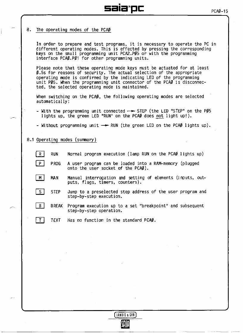
8. The operating modes of the PCA0
In order to prepare and test programs, it is necessary to operate the PC indifferent operating modes. This is effected by pressing the correspondingkeys on the small programming unit PCA2.P05 or with the programminginterface PCA0.P01 for other programming units.
Please note that these operating mode keys must be actuated for at least0.5s for reasons of security. The actual selection of the appropriateoperating mode is confirmed by the indicating LED of the programmingunit P05. When the programming unit connector of the PCA0 is disconnec-ted, the selected operating mode is maintained.
When switching on the PCA0, the following operating modes are selectedautomatically:- With the programming unit connected —— STEP (the LED "STEP" on the P05
lights up, the green LED "RUN" on the PCA0 does not light up!).
- Without programming unit —*-RUN (the green LED on the PCA0 lights up).
8.1 Operating modes (summary)
[ R ] RUN Normal program execution (lamp RUN on the PCA0 lights up)
P] PR06 A user program can be loaded into a RAM-memory (pluggedonto the user socket of the PCA0).
MAN Manual interrogation and setting of elements (inputs, out-puts, flags, timers, counters).
STEP Jump to a preselected step address of the user program andstep-by-step execution.
IT] BREAK Program execution up to a set "breakpoint" and subsequentstep-by-step operation.
Tl TEXT Has no function in the standard PCA0.
ËYRJ

PCA0-)6 sata pc8.2 Detailed description of the operating modes
[*Rl RUN Normal program execution
The PCA0 is automatically in the RUN-ntode when switching on ifthe programming unit is not connected.
]*P] PROG Programming
A program can be stored in a RAM-memory (on the user socket ofthe PCA0) or overwritten (corrected).
Step Code Operand[A] x x x x [Ë] x x x x x x
[Fjxx x x x x or [B deleting a wronglyentered line
[+] Terminates the input
Test program BB °"" B B
[Ml MAN ** Manual interrogation or setting of elements
(Elements = inputs, outputs, flags, counters, timers)
Interrogation: [ÂJ x?x——— "Y °f - ^ in the operandElement address
Setting: [A]xxx[E] [T]-*——or@]Element address
[Si STEP [V]—--Display showing where the program is.
Jump to the preselected step address of the user program[A] 139 B———Program jumps to step 139, then
[+] [+]... step-by-step execution of the program with the
result of the logic operation being checkable ACC = 1*
Switching to RUN is always possible.
In case of parallel programs, only the activated paratlelprogram is executed in the STEP-mode
[JBj BREAK Interruption of the program run and subsequent step-by-step operation
B———Display showing where the program is
B B .... step-by-step execution of the program with the
result of the logic operation being checkable -j^-ACC - 1*.
Switching to RUN is always possible.
In case of parallel programs, alt programs are executedsimultaneously (as in the RUN-mode).
Setting of a breakpoint
[A] 820 B ——— program runs up to step 820, then
BE] - - - - step-by-step operation skipping the "critical" point.
*) ACC = accumulator is used to indicate the result of the logic combi-nation. If ACC = 1, (conditions of the logic combination fulfilled),the following switching instructions are executed.
**) If the address of a timer or counter is preceded by a 3 (e.g.3260 for counter 260), the value of this register can be read orentered manually with [Ë] value [+1.

PCA0-17
9. Programming in three easy steps
Combined programmingC incl. arithmetic and index register
B Programming according to flow-chart
A Programming according to a ladder diagram
The PCA0 is equipped with a very efficient instruction set, level (fH).Thanks to this instruction set even complex control problems can besolved easily. The programs of the PCA0 can be used at any time withother series of the SAIA-PC system family, too. This enables yourcontroller to "grow" according to your requirements, without having towrite new programs every time.
In order to make the start of programming easier for the beginner, theperformance of the PCA0 is split up into three easily understandablesteps. Maybe your control problem is so easy that it can be solved evenon level A.Let's start programming with a tadder diagram, attrtough this is no ionger suitabiefor modern programming, because process runs are often particuiariy difficuit torepresent in reiay !ogic.But you wi!! see that your PCA0 understands any tadder diagram.

PCA0-18 sata pcProgramming according to ladder diagram
12 14 n Ladder diagram
PROG
CPU
MEMORY
i)N
0OUT
027 024
17
027 (43)
—B-024 (40)
Program
1 STH 22 ANH 43 OUT 27? STH 75 OUT 24
JMP l
The program prepared according to a ladder diagram is entered into theuser memory (RAM) by means of the programming unit. In the RUN-mode, theCPU reads this program line by line and checks the relevant inputs. If oneof the contacts 12 or 14 is closed, an "H" (High = voltage greater than+19V) is stored in the CPU and after reading the 2nd line it is AND-connected with the latter. If both contacts are closed (H), the state ofthe accumulator = 1 (ACCU = 1) and the output 27 is activated, the con-tactor at output 27 is actuated.
In line 4 the CPU processes input 7. If this contact is closed, output24 is activated, the indicating lamp lights up.
We can combine more of these logic operations, because our user memory of4K = 4096 program lines is extremely large. If all logic operations havebeen programmed, we have to tell the CPU to return to line 1. In thisway, our program is permanently run cyclically at a high speed, and allalterations are immediately transferred as logic operation results fromthe inputs to the outputs.

satapc PCAP-19
Instruction set (À) ladder diagram
The instructions available for programming such logic operations areclassified into logic instructions and switching instructions.
Their functions are listed in the following table. Do not let yourselfbe confused by the large number of functions. When programming accordingto a ladder diagram only about 8 of them are used frequently, which youwill soon know by heart.
Step address numerica! code
STEP CODE
Mu<w*ri Mntmoca! code cod*
01 STH02 STL
Logic ————— —————tnstruc- 03 ANHtions 04 ANL
1 05 ORH.i*) 06 ORL
' T** 07 XOR
08 NEC
09 DYN
Switching 10 OUTtnstruc
11 SEO) 12 REO
' — r** 1 3 coo
Time 14 SIRtnstructions
Jump 20 JMPtnstructions
, ... 00 NOPAuxtharytnstructions
Etement or jump address
OPERAND
twatructton
Start HighStart Low
And HighAnd Low
Or HighOr Low
Exclusive Or
Negate ACCU
Dynamic Control
Set Output withStatus of ACCU
Set OutputReset Output
Complement Output
Set Timer
Unconditional Jump
No Operation
AccumulatorsACC = 1\ t / LED displty— — on SMA°PC/ p<. programing' Input unit
Dttchptton
f Start of an operation: 1 High\ Element interrogated for / Low
/ And-operation of ^ High\ ACCU with element interrogated for / Low
( Or-operation of j High\ ACCU with element interrogated for ) Low
Exclusive-or-operation ofACCU with addressed element
Invert state of the ACCU
Signal edge triggering ordynamic control of an operation
Transfer the stateof the ACCU to an output or a flag
Set output or a flag and storeReset output or flag and store
Interrogate state of output or flagand set it to the opposite state
Set timer to presetected value and start itTime value in '/;os (resp. '/iocs)
Unconditional jump to step address
No operation

PCA0-20 sata pcThe program line
Each instruction in the user program consists of 1 line (in certain casesof 2 lines). In addition to the line number or step address (STEP) a linecontains the instruction code (CODE) and operand (OPERAND). The instructioncode indicates "WHICH" instruction is to be executed, and the operanddetermines "WHERE" this instruction is executed.
Structure of the program or instruction line:
STEP CODE OPERAND
Mnemonic code
orNumerical code
Line number orstep address
Instruction code"WHICH"
y vAddition to theinstruction code "WHERE"
vInstruction
Program line
STEP The line no. defines the position of the instruction in the usermemory. Decimal numbering from 0...409S (4K).
CODE Depending on the programming unit the instruction code can beentered in a 3-digit mnemonic code or in numerical cod*e from0 to 31. The mnemonic code is based on abbreviations of thecorresponding English instructions. It is therefore easy toremember and understood internationally.
OPERAND Here, the address of an element (input, output, timer, counter orflag) or in case of jump instructions the destination address(line no.) is entered.
Timing and counting instructions consist of two lines. In the second line,the appropriate time or counter value appears in the operand.

PCA0-21
(Al) A first programming example
Before starting to enter the program, it must be noted down in mnemoniccode on paper. For this, it is advantageous to copy the programminglists added at the end of this manual.
027 (43)
17024 (40)
Step
-6
Mnemo .code
Numeric.code
Operand
2?
Comment
For programming and simulation we establish the same configuration asdescribed in section 5. All the following examples always refer tothe small PCA0 with only 16 or 20 inputs. For the bigger versions theoutput addresses are added in brackets respectively.
With the programming unit PCA2.P05 the above program can now be enteredinto the plug-in user memory (RAM or R95).
-operating mode PROG
2)
3)
4)
-,9STEP Mnemonic Numerical OPERAND
code code
0000
23TT45c
(NOP)(STH)(ANH)(OUT)(STH)(STH)(OUT)/ 1MD\
0001031001011090)
00002427H* 3)724i
1) Selection of the step address 0 (contents with [El = Enter.
= Address) and erasure of the
2) Every following [Ê] increments the step address by 1 and the contentsof the old program line are erased and prepared for the new input.
3) 8 was entered accidently instead of 7. Correction with [C] andrepetition of the instruction. The step address is not incrementedas a result of [ci.
4) The last input must be stored with [j] , or

PCA0-22
After entering the program it is recommended to compare the programstored in the user memory step by step with the program previouslywritten down:
Now of course we want to test whether the program runs.
[s] ——— The LED indicating operating mode "STEP" lights up
[A] SB ———The program execution should start at step 1
[R] ———The LED "RUN" lights up, the program is running
Now close contacts 12 and 14 ——the LED of 027 lights up. Uponclosing 17——024 lights up.

satapc PCA0-23
Parallel connection
Ladder diagram
027 (43)
Program
Step Mnemo.code
Nunteric.code
Operand Comment
/M/PZ?
4?
Note:
- Every OR-instruction starts a new branch of the parallel connection atthe very beginning on the left. Afterwards, AND-operations can be addedagain to this parallel branch. The whole program, however, is con-sidered as only one logic operation.
- If the logic operations are finished, as many actions as desired (de-pending on this logic operation) can be added.
- Enter the program as follows:
[f]—* LED "PROG" for programming mode lights up
-The PCA0 is prepared to accept the above programfrom step address 10
Continue to proceed as described in example A1, but make the PCA0execute the program from step 10 on with [S] [À] EE BE-

PCAP-24 sata pc(A3j OR is "stronger" than AND and getting to know other "elements"
The following contact arrangement must be p
, 12 1 ——— 027(43)"< n tLE _J Ü '
One is tempted to prepare the program as abat the beginning of a parallel branch, theresult:
" * - 16< * I o"" ß2-?-*f?3)*i n^^L^^ ^ *
There are two possibilities of implementing
— ft "i-yI6_J^ 13.
The contact 16 is programmed in both parall
b) 12r < ——— . 024 (40)... ^ , , ,J... _ j
13 ^
) 027 (43)is/ -*- jn _,
rog rammed:
TCTU 4toJ n X?AM%/3ORK\3
ove. However, as OR is alwaysfollowing circuit would be the
the desired function:
r—20 STH 01 621 ANH 03 222 ORH 05 623 ANH 03 324 OUT 10 27
L— 25 JMP 20 20
el branches.
] — 20 STH 221 ORH 322 OUT 2423 STH 624 ANH 2425 OUT 27
' — 26 JMP 20——— !/ ————————————————— 0 !< ————— L ———— t
024 LJ(40)
Programming is performed in two steps. As evident from possibility b)outputs can be used as desired in other logic operations, too.
L. ^
UMiSHYRjn

PCA0-25
It would be a pity to sacrifice an extra output for this easy task. There-fore, every PCA0 contains 712 FLAGS!
The elements and registers of the PCA0:
Elements Register
ADDR. ADDR.
999
765764
320
319
288
287
256
Retentive flags H ornon-volatile flags
Flags M*
32 counters C*, whichcan also be used asflags
32 timers T* or counters C*
4 hardware timers, providedthat the module PCA0.H20is attached
max. 64 inputs Iand outputs 0
319
256
64 registers*as counters ortimers at 16 bit
*) By inserting the jumper "NVOL"on the CPU all of theselocations can be madenon-volatile, i.e. whenswitching off the PCA0 thesedata are not lost.
With the aid of a flag the ladder diagram can now be drawn as follows:
Substitution Intermediate Finalresult result
ADDRr-303132
333435
L-36
NC010510
01031020
MNCSTHORHOUT
STHANHOUTJMP
OPRD23
400
40062730
Interrogating 12OR 13Storing the intermediate result
Interrogating flag 400 (and thusAND 16Output of the result via 027Return to the beginning
on flag 400
the OR-function)

PCA0-26 satapc\4) Two kinds of start/stop circuit with latching contactor
a) Presented in a ladder diagram
The following classical example is known from the technique ofcontactors:
Start11
024 (40)
Stop10 024 (40)
D——
Program
ADDRr— 40
4142
434445
L- 46
NC010510
01031020
MNCSTHORHOUT
STHANHOUTJMP
OPRD
Jl401 J
4011%24 J40
> Start
> Stop
As in example A3 programming is performed using a flag. As evidentfrom the program, the normally open contact 10 is connected with "H",as 024 can be activated only with contact 10 being closed.
This way of programming is fail-safe against wire break. If a wirebreaks in the lines of 10, 11 or 024, 024 is always inhibited.
b) Logic diagram presentation
Start
Stop
11-o-
10-O-
Program
& 024 (40)
ADDRr*-50
5152
5354
- 55
NC010311
021220
MNCSTHANHSEO
STLREOJMP
OPRD11924 J012450 J
> Start
* Stop
SEO (11): Set Output With this instruction an element (output or flag)is continuously set until it is reset with REO.
REO (12): Reset Out- With SEO/REO we are able to program a flip-flop,put Both instructions are executed only if the
result of the logic operation is positive (ACCU = 1),
The "Set" instruction of example b) is executed only if 10 = H. Ifboth keys are pressed, the "Reset" instruction takes precedencebecause of the AND-operation.
This way of programming is also fail-safe against wire break.
saiapc PCA0-27
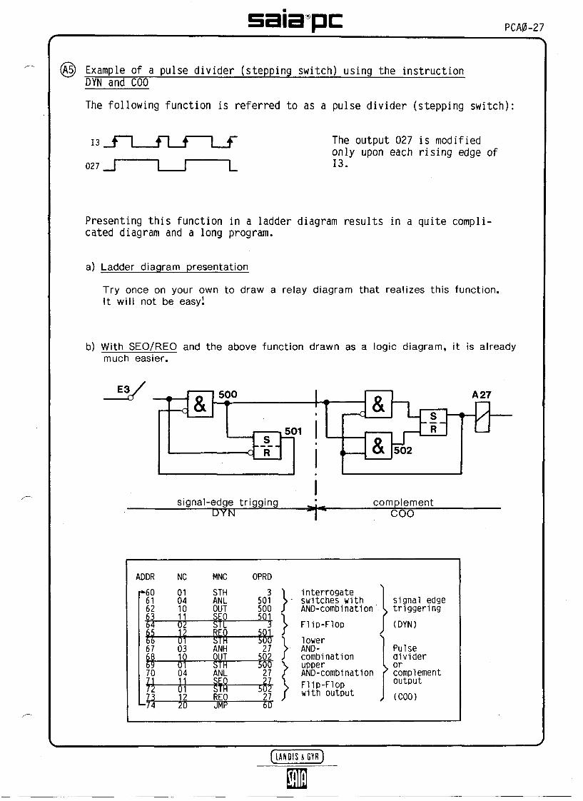
Example of a pulse divider (stepping switch) using the instructionDYN and COO
The following function is referred to as a pulse divider (stepping switch)
027 _J LThe output 027 is modifiedonly upon each rising edge of13.
Presenting this function in a ladder diagram results in a quite compli-cated diagram and a long program.
a) Ladder diagram presentation
Try once on your own to draw a retay diagram that reaiizes this function.)t wit) not be easy!
b) With SEO/REO and the above function drawn as a togic diagram, it is atreadymuch easier.
E3V ^— c A "!!OL
0
.A--- r R
———
,501
signai-edge triggingDYN ^
<
r-
< —
&
&"L502
S*R
A 27
Ü
compteraient** coo
ADDRr*606162636465DD6768557071727374"
NC0104101102I?Ol031001041 1
1220
MNCSTHANLOUTSEOSTLREOSTHANHOUTSTHANL8
REOJMP
OPRD3 1
501 S500 /501 1
3 S501 J500 127 )502 J500 \27 /552 j27 J60
interrogate* switches with
AND-combination. Flip-Flop
lower> AND-
combination> upper
AND-combination> Flip-Flop
with output
signal edgetriggering(DYN)
Pulsedividerorcomplementoutput(COO)
(HNOIS&GYR)
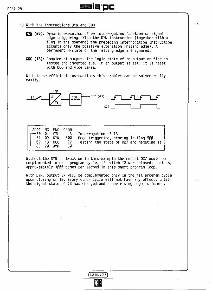
PCA0-28 satapcc) With the instructions DYN and COO
DYN (09): Dynamic execution of an interrogation function or signaledge triggering. With the DYN-instruction (together with aflag in the operand) the preceding interrogation instructionaccepts only the positive alteration (rising edge). Apermanent H-state or the falling edge are ignored.
COO (13): Complement output. The logic state of an output or flag istested and inverted i.e. if an output is set, it is resetwith COO and vice versa.
With these efficient instructions this problem can be solved reallyeasily.
500
,COO_ .027 (43) ,3
027
ADDR NC MNC OPRD-—60 01 STH 3
61 09 DYN 50062 13 COO 2763 20 JMP 60
Interrogation of 13Edge triggering, storing in flag 500Testing the state of 027 and negating it
Without the DYN-instruction in this example the output 027 would becomplemented in each program cycle, if switch 13 were closed; that is,approximately 3000 times per second in this short program loop.
With DYN, output 27 will be complemented only in the 1st program cycleupon closing of 13. Every other cycle will not have any effect, untilthe signal state of 13 has changed and a new rising edge is formed.

sstapc PCA0-29
The software timers with switch-off delay
In example A3 all elements of every standard PCA0 and their correspondingaddresses were shown. The 32 software timers reside on the addresses256...287. For each address there is a 16-bit register in which valuesfrom 0...65535 can be stored.
For setting and starting a software timer a two-line instruction isnecessary:
STR (14) 256:20:
Starting the timer with address 256Loading the corresponding register with the value 20.(Direct input up to 2047 for code 00).
T256
When the CPU reads this instruction, the logic state of timer 256 isset to "H" and the register value is reduced according to the time base(1/10 s). After this has been done 20 times (20 x 1/10 s = 2 s) thelogic state of the timer 256 is "L" again.
With this basic function a switch-off delay can be implemented easily:
17
027 (43) 1256
027 (43)
t = 7.5s
ADDR NC MNC OPRD—70 J2M STH 7
7172
14 STR 25675
Interrogation of 17Set timer and startInput of time in 1/10S 2-line instruction
73 01 STH 25674 10 OUT 27
— 75 20 JMP 70
Interrogation of timer T256Transfer to 027
Upon closing of 17 the timer is set and its logic state is set to "H".The time does not start to run down before 17 is opened. (In fact, thetime starts to run down at once. But as the timer is set again in thenext program cycle after some 100us with 17 closed, the time starts torun down again from the very beginning, until the signal present at17 is removed, i.e. the contact 17 opens).
If 17 is closed again while the time is running down, the timer is resetand started again.
P.S.: As evident from chapter 5 the time base can be reduced to 1/100Sby removing the jumper "1/10" on the CPU thus enhancing theresolution.
( L A N Q I S X G Y R J

PCA0-30
(AT) Use of the hardware timer module PCA0.H20
In addition to the 32 precise software timers (which are included inevery standard version) 4 hardware timers (additional module) areavailable in order to use time functions in the programs.
The 4 hardware timers with the addresses 64...67 can be operated in asimilar way to the software timers.
Software timers Hardware timers
STR00
256t
REOSEO
6464
For the hardware timer the time range and time are set directly on thehardware module PCA0.H20.
Example according to A6:
17
027 (43) HT 64
027 (43)
ADDR NC MNC OPRD— 80 j STH 7
8182
1211
REOSEO
6464
83 01 STH 6484 10 OUT 27
-85 20 JMP 80
Interrogation of 17Start hardware timer HT 64
Interrogation of HT 64Transfer to 027
As with the software timer, the time starts to run down at once in caseof the HT 64, too. As long as 17 is switched on however, HT 64 is resetin each program cycle. The time actually starts to run down when 17 isopened resulting in the above switch-off delay.

PCA0-31
(A8) Software timers with fleeting-on delay with external time input inBCD-code
The PCA0 also allows reading the BCD-values directly into the registersof the timers and counters. As a result, time values can be changed atany time with the BCD-switch. If we use the input simulation unitPCA2.S05 as described in chapter 5, we can see that the input addresses18...115 are acted upon by a two-digit BCD-switch. For this, the BCD-switch transmits the following signals to the input:
Binary signals present at 4 inputs (BCD-switch)
1 12
23 = 8
LLLLLLLLHH
1 13
2? = 4
LLLLHHHHLL
1 14
21 = 2
LLHHLLHHLL
1 @
20 = 1
LHLHLHLHLH
Decimalvalue
0123456789
Now, the STR-instruction can expanded in such a way that the delay timecan be directly read off the BCD-switch.
Code OPERAND
SIR (14)NC
256@
1st line2nd line
BCD-switch(2 pieces)
(En) : The highest input address of the two BCD-switches (e.g. @) isintroduced into the operand.
NC : The numerical code has the values 16, 17 or 18 with the followingmeanings:
16 value 0... 99 x time base = 0...9.9s*or 17 value 0... 990 x time base = 0... 99s*or 18 value 0...9900 x time base = 0...990S*
*) These values result from the standard clock rate of 1/10s. It canbe changed to 1/100S by removing the jumper "1/10".

PCA0-32
Problem:
The time range 1 to 99s must be set with the external BCD-switch. Theinputs 18...15 are acted upon by the two BCD-switches. The time functionis to have a fleeting-on delay.
Because of the OYN-instruction only the rising edge of 10 is taken intoaccount, enabling the timer 258 to run down without interruption.
T258
024 (40)
402
024 (40)
Program:
23?! ,1,9 23222'?"
Tens Ones
ADDRr— 90
919293
9495
L-96
NC01091417
011020
MNCSTHDYNSTR17
STHOUTJMP
OPRD0
40225815
2582490
Interrogation of 10Edge triggering, timer is set only in the 1stStart timer and set it to the external valuex 10 x 1/10S using the inputs 8... 15
Interrogation of timerTransfer to 024
cycle
If the same function has to be performed by a hardware timer, justreplace the lines 92 and 93 as follows:
ADDR9293
94
NC1211
01
MNCREOSEO
STH
OPRD6666
66
> Start hardware timer HT 66
Interrogation of hardware timer HT 66

PCA0-33
(A9) Switch-on delay with two new, very useful instructions
Problem:
t = 12s
287
TMR
17
.027 (43) T287
027
In case of the switch-on delay the timer is also started by the risingedge of 17 as in case of the fleeting-on delay. However, output 27 shouldbe switched on only after the time has elapsed.order to activate 027, the rising edge of 17 must have been generated andthe timer run down (L). This can be shown by means of the following logicdiagram:
402
027 (43)
As we are working with an intelligent PC, elapsing of the time has to bedisplayed on the programming unit. This is achieved with the instructionPTC (31): "Display Timer or Counter". Provided that this instruction isExecuted at least once every second (which does not constitute a problemin circulating programs), the actual contents of the corresponding timeror counter are displayed in the operand field of the P05. Activation ofthe DTC is effective only if the ACCU = 1. Therefore, it needs to be pre-ceded by the instruction SEA (19) 0: "Set Accumulator".

PCA0-34 sata pcProgram:
ADDRr 10%101102103
104105106
107108
L-109
NC01091400
010410
193120
MNCSTHDYNSIR00
STHANLOUT
SEADTCJMP
OPRD7
402287120
40228727
0287100
Interrogation of 17Signal edge triggeringStart timer and set it to120 x0.1s = 12s
Interrogation of the edge flag of 17AND timer run down (L)then output to 027
Set ACCU = 1Display of the timer contents
If this function is to be performed by the hardware timer HT 67, thelines 102/103 and 106 must be replaced as follows:
ADDR102103
106
NC1211
04
MNCREOSEO
ANL
OPRD6767
67
Start hardware timer HT 67
AND HT 67 run down (L)
satapc PCA0-35
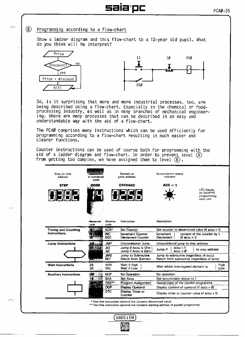
Programming according to a flow-chart
Show a ladder diagram and this flow-chart to a 12-year old pupil. Whatdo you think will he interpret?
[ Price - discount1
Bill
11
^
050
10 050
-2Ï2————L
So, is it surprising that more and more industrial processes, too, arebeing described using a flow-chart. Especially in the chemical or food-processing industry, as well as in many branches of mechanical engineer-ing, there are many processes that can be described in an easy andunderstandable way with the aid of a flow-chart.
The PCA0 comprises many instructions which can be used efficiently forprogramming according to a flow-chart resulting in much easier andclearer functions.
Counter instructions can be used of course both for programming with theaid of a ladder diagram and flow-chart. In order to prevent level (/t)from getting too complex, we have assigned them to level (B).
Step (or line)address
STEP
SBB§in nutwefica)
code
COM
Element orjump address
OPERAND
BAccumulators status
indicator
ACC = 1
<Mttmencai Mnemo- Instructioncoda =_ï code
Description
Timing and Countingtnstructions
Set Counter Set counter to determined value (if accu = 1)tncrement CounterDecrement Counter
tncrementDecrement
content of the counter by 1(if accu = 1)
Jump tnstructions Unconditional Jump Unconditional jump to step address
RETJump to SubroutineReturn from Subrout
Jump to subroutine (regardless of accu)Return from subroutine (regardless of accu)
Wait Actions 25 W.H Wait if High j element is
Auxiüary tnstructions NOPSEAPAS*
No Operation No operationSet Accu Set accumulator status to 1Program Assignment Assignment of the parallel programmeDisptay Operand Disptay content of operand (if accu = 0)
Display timer or counter value (if accu = 1)
* Two line instruction (second line contains determined value)** Two line instruction (second tine contains starting address of parallel programme)

PCA0-36 satapc(Bl) Upwards/downwards movement
Upperlimit switch 14
Start 10
Lowerlimit switch 17
t DOMN
UP
(027) (43)
Problem:
As a result of a pulse at 10 the loadL must be moved upwards (UP = 027)until 14 is opened. Then, the load mustbe lowered again (DOWN = 024) until 17is opened.
Additional conditions:
- If 10 is permanently on this sequencemust be continuously repeated.
- After a voltage break an upwardsmovement must not be triggered beforea pulse is present at 10.
- Note: Before starting the program theswitches 14 and 17 must be closed.
Problem solving by means of a flow-chart:
Flow-chart Program Comment
UP( (027) !
110
111 ] SEO (11) 27
112
113114
115
116
117 ( JMP (20) 110
Wait as long as 10 isopen (low).If 10 is closed, then ...
Set output 27 (UP)
Wait as long as 14 isclosed (high).If 14 is opened, then
Reset 027 (STOP) andset 024 (DOWN)
Wait as long as 17 isclosed (high).If 17 is opened, then
Reset 024 (STOP)
Return to the beginning

PCA0-37
As evident from the example, a sequence is described step-by-step whenprogramming according to a flow-chart. The stages of the process are splitup into conditions (wait for an input state) and actions (set or resetoutputs).
If we follow this program in step-by-step operation in the operating modeSTEP (key sequence ([S][A] 110 [+JB )...., we will notice that theprocessor itself stays in the wait loop, until the condition for continuingis fulfilled. This means: the program does not permanently circulatecyclically like the program prepared with the aid of a ladder diagram, butthe program is executed according to the progress of the process.
This has three important advantages:
- The programs are made clearer, because they show the individual steps ofa process and not an abstraction in a ladder diagram which is not relatedto the process.
- Only those program sections are processed which are of importance for thecurrent stage of the process. As a result, possible malfunctions resul-ting from the execution of irrelevant program parts are avoided. Mostimportantly, however, the reaction time between step condition and actionis considerably reduced.
- If the slide L stops after the first up-/down-movement, it is possibleto exactly localize the error in theprogram by means of the programmingunit in the operating mode "STEP", [+][jj ... At step 110, WIL 0 isdisplayed. Moreover, the LED of 10 indicates that this input has not beenactivated. Therefore, the error can be quickly narrowed down to thecontact or the connecting line of 10.

PCA0-38 sata pc) Up-/downwards movement with timer and counter
Problem:The movement described in example 61 is to be effected not only once buta certain number of times (e.g. 5 times) and a pause of 2.5s must be madeeach time at the points where the direction is reversed.
Solution:Flow-chart
closed
Set counterto 5
UP (027)
open
STOP! (027)Set timer
to 2.5s
run downDOWN (024)
openSTOP! (024)
Set timerto 2.5s
run downCounter -1
Return
Programm
130
131132
133 ! SEO (11) 27 !
134
146 ! STH (01)300!
T/JIO (21) 133\-
<148 ^JMP (20)
CommentWait, as long as 10 isopen (low).If 10 is closed, then .,
Set counter 300 to 5
Set output 27 (UP)
Wait as long as 14 isclosed (high).If 14 is opened, then
Reset 027 (STOP).Set timer 256 to 2.5s
'Wait while timer isrunning down (high)
Set output 24 (DOWN)
Wait as long as 17 isclosed (high).If 17 is opened, then
Reset 024 (STOP)Set timer 256 to 2.5s
Wait, while timer isrunning down (high)
Decrement counter 300by 1
Test counter, if0 (high)
If yes, jump
Return to the beginning

PCA0-39
Contrary to problem B1, in this example timers were also integrated intothe action parts. One must wait for these to run down in additional con-ditional loops (WIH 256).
The use of the instruction SCR (15): Set counter is new.This is a two-line instruction (as in case of the timer). In our examplethe counter is set to 5. As long as the counter C300 is greater than zero,its logic state is "H".
5 A 3 2 1H
With the instruction DEC (18): Decrement Counter the counter state isdecremented by 1 in each run.
The interrogation instruction STH 300 allows to continuously check the logicstate of the counter. If the ACCU = 1 after the interrogation, the countercontents are still greater than zero and another loop must be executed.Returning to the beginning of a loop is effected with the conditional jumpinstruction JIO (21): Jump if ACCU = 1.
In other words: If the counter is greater than zero, another loop must beexecuted: If the counter state is zero, no more jumps are effected andthe last JMP-instruction leads back to the program beginning.
If the hardware timer HT 65 is used instead of software timer T256, thecorresponding program parts need to be replaced as follows:
STR 256^00 25 ,
WIH 256J
REO 65SEO 65WIH 65
[LANQIS&GYR]

PCA0-40 satapcWhat needs to be done, if we want other functions to be performedtogether with the upwards/downwards movement?
In this case, we prepare a second or third parallel program out of the16 parallel programs provided for each PCA0-standard version!
Problem:
Simultaneously and independently of program 32 a blinker with a flashingtime of 0.3s has to be generated in a parallel program and the actualcounter state of the upwards/downwards movement has to be continuouslydisplayed on the programming unit.
Program:
1202122
r-123
12425262728
*-129
PAS (29) (D00 130
DTC (31) 300
STH 2ANL 257SIR 25700 3
COO 16JMP 1 23
llhe parallel program number (T) is assigned toJ the up/down program starting with step address 130
The counter state of counter 300 ]must be indicated continuously
/
^Output 16 blinks every 0.3sas soon as 12 is closed
.
Parallelprogram (0)
In the very beginning, we use the two-line instruction PAS (29) 1 (programassignment) to assign the number (T) to the parallel program starting atstep address 130 in the so-called assignment part.
Other parallel programs can be added easily with PAS (2) or PAS (3).
The program at step addresses 123 to 129 is a so-called circulating pro-gram without wait loops. It may include other functions such as monitoringor other permanently performed tasks. This parallel program without assign-ment is automatically given the number @.
If you want to execute PP0 at the same time from step address 123 on andPP1 from step address 130 on, then jump to the start address 120 with thefollowing assignment: [s] [A] 120 [1J [R].
Now, test both programs! Both are executed separately and asynchronously.As mentioned above, up to 16 parallel programs of any desired length canbe executed with the PCA0 (as with all SAIA-PCs).
PCA0-41
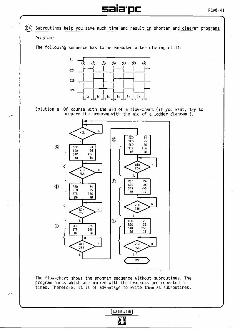
(B4) Subroutines help you save much time and result in shorter and clearer programs
Problem:
The following sequence has to be executed after closing of 11:
025
026
-s Is Is Is Is Is
Solution a: Of course with the aid of a flow-chart (if you want, try toprepare the program with the aid of a ladder diagram!).
SEOSEOSIR00
242625610
REO 24SEO 25SIR 256
10
SEOSEOREOSIR00
24252625610
LREOSEOSIR00
242625610
The flow-chart shows the program sequence without subroutines. Theprogram parts which are marked with the brackets are repeated 6times. Therefore, it is of advantage to write them as subroutines.

PCA0-42
Solution b: with subroutine
Main program
@
******************* Main programADDR160161162163164165166167168169170171172173174175176177178179
NC2611112312112312231111122312112312122320
MNCMILSEOSEOJMSmiSEOJMSREPJMSSEOSEOREOJMSREUSEOJMSREUREOJMSJW
OPRD1
2426182 -**2?25182 -**Z5*182 =*"2"4*2526182 -"23*26182 -"25*26182 -w
Mait, if
:>Jump to
^>Jump to
:>Jump to
>Jump to
^Jump to
^>Jump to
11 is open
subroutine
subroutine
subroutine
subroutine
subroutine
subroutine
182
182
182
182
182
182
Thanks to the instruction JMS (23): Jump to Sub-routine the same program parts must be pre-pared only once. Every subroutine ends withthe instruction RET (24): Return with theoperand 0.
Subroutine "182"
SIR 25600 10
RET 0
Subroutine 182 (wait 1s)
-182 14 SIR 256183 00 00 10184 25 WIH 256185 24 RET 0
It is also possible to program thesubroutine of the subroutine of thesubroutine i.e. down to the 3rdlevel.

sata^pc PCA0-43
Indexing, arithmetic and check sum
At the programming level C you are already a professional!
Certainly, one can live happily without climbing up to this level. But,once you are up here, you will be proud of yourself and the PCA0 forhaving prepared your programs in such a nice and efficient way.
These are the remaining instructions for the software levelSAIA-PC system family.
of the
Step address
STEP
Instruction innumerical code
CODE
Element or jump address
OPERAND
Accumulator
ACC =1
Display onSAIA°PCprogrammingunit
Transfer instructions
Arithmeticinstructions
Indexinginstructions
Special instructions
These instructionsconsist of two lines
Num.code
15
15
16
2728
29
29
Mnemo .code
SCR
19207T2223?4*2526TT
SCR27282930
SEI
INIDEI
PAS
PAS
Instruction
Set counter>
'2nd line
"*
Set counter
^2nd line
Set index
Incr. indexDeer, index
OPERAND
18
30... 34
Description
Read- in 5x4 bit BCDOutput 5x4 bit BCDOutput 8 bit binaryOutput 12 bit binaryOutput 16 bit binaryRead- in 8 bit binaryRead-in 12 bit binaryRead-in 16 bit binaryTransfer counter tocounter resp. IR
Addition +SubtractionMultiplication xDivision :
Set index register topreselected value
Increment ) the indexDecrement J reg. by 1
Changing the number ofactive parallel programs
Check sum
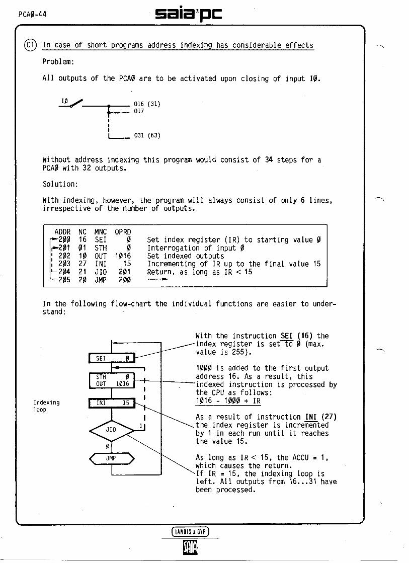
PCAP-44 sata^pc(C1) In case of short programs address indexing has considerable effects
Problem:
All outputs of the PCA0 are to be activated upon closing of input 10.
016 (31)017
031 (63)
Without address indexing this program would consist of 34 steps for aPCA0 with 32 outputs.
Solution:
With indexing, however, the program will always consist of only 6 lines,irrespective of the number of outputs.
ADDR NC MNC OPRDr-200 16 SEI 0f*201 01 STH 0' 202 10 OUT 1016! 203 27 INI 15L-204 21 JIO 201-205 20 JMP 200
Set index register (IR) to starting value 0Interrogation of input 0Set indexed outputsIncrementing of IR up to the final value 15Return, as long as IR < 15
In the following flow-chart the individual functions are easier to under-stand:
Indexingloop
With the instruction SEI (16) theindex register is set to 0 (max.value is 255).
1000 is added to the first outputaddress 16. As a result, thisindexed instruction is processed bythe CPU as follows:1016 - 1000 + IR
As a result of instruction INI (27)the index register is incrementedby 1 in each run until it reachesthe value 15.
As long as IR< 15, the ACCU = 1,which causes the return.If IR = 15, the indexing loop isleft. All outputs from 16...31 havebeen processed.

satapc PCA0-45
(C2) Thanks to upward and downward indexing high flexibility is obtained
Problem:
Upon closing of 10 the outputs 016...31 (63) are to switch on one afterthe other every 0.3s. Upon opening of 10 the outputs 031 (63)...16should be switched off again in reverse order every 0.1s.
Solution:
Mai t whilecontact 0is open
Indexingloop forstaggered <switcning-on (0.3s)
SEOSIR00
10352602
Wait whilecontact 0is closed
[SEI 25]
Indexingloop forstaggered <switching-off (0.1s)
REOSIR00
1035260
1
\
0.3s O.ls
10015 (31)017018
031 (63)0.3s
ADDR
21011
r— 212! 13
14' 15' 16*— 217
21819
r*-22021222324
' —— 25226
NC
26161114
252721
25161214
25282120
MNC
MILSEISEOSTR00
WIHINIJIO
WIHSEIREOSTR00
WIHDEIJIOJMP
OPRD
00
10162603
26015
212
015
1016260
12600
220210
TURN-ON PHASE
016 + 1000 = 1016
031 -
TURN-C
031 -016 +
—— —
16 = 15
)FF PHASE
16 = 151000 = 1016
The upper indexing loop is very similar to that in example C1. In thelower loop the index register is set to 15 first. In the first run REO1016 - 1000 + 15 = REO 31 acts upon output 31. The instruction DEI (28)decrements the value of the IR by 1, as a result of which output 30 isswitched off in the next run, etc. As soon as the IR = 0, no furtherreturn is effected, the indexing loop is left.
You will have noticed that in case of the version with relay outputs, apause is made after 4 relays respectively. This is due to the fact thatthe 4 unoccupied addresses 20...23 are processed too.
(LANBIS&GYR)

PCA0-46 sata pc(C3) Even calculating is possible with the little PCA0
The 64 counter registers of the PCA0 can be used in many ways. In connec-tion with the instructions SIR and SCR we have only dealt with the codes00 and 16, 17, 18 of the second line. As evident from the followingtable, 32 functions are available.
With the codes 01...15 the area from 2048 to 65535 can be reached.
With the codes 19...26 8- to 20-bit digital values can be loaded into thecounter register or transferred to elements.
Finally, with the codes 27...30 arithmetic functions can be performed.
Code 31 serves to transmit values from index registers to a counterregister or from one counter register to another.
1.line
2.H ne
Mnemoniccode
SIR//SCR
Numeri-cal code
14//15
00010203040506-%7_0809101112131415
161718
1920212223242526
27282930
31
Operand
256. ..319
xxxx
xxxx
] Highest addr.^of 8 subse-J quentelements
Highest addr.of the'sequence ofelements
XXXXXXXXXXXX
iii
Explanations
Address of the register
Value in the + 0operand + 2048
+ 4096+ 6144+ 8192+ 10240+ 12288+ 14336+ 16384+ 18432+ 20480+ 22528+ 24576+ 26624
Value in the + 28672operand + 30720
2 x 4 bit BCD x 12 x 4 bit BCD x 102 x 4 bit BCD x 100
Read instr. for 5 x 4 bit BCDOutput instr. for 5 x 4 bit BCDOutput instr. for 8 bit binaryOutput instr. for 12 bit binaryOutput instr. for 16 bit binaryRead instr. for 8 bit binaryRead instr. for 12 bit binaryRead instr. for 16 bit binary
Addition *i with a constantSubtraction I (0...25S) or withMultiplication [the contents of aDivision J T/C (256. ..319)
iii = 0: value of index registeris loaded into counter
iii = 256. ..319: Value ofcorrespondingT/C is loadedinto counter
satapc PCA0-47
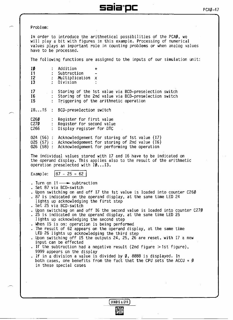
Problem:
In order to introduce the arithmetical possibilities of the PCA0, wewill play a bit with figures in this example. Processing of numericalvalues plays an important role in counting problems or when analog valueshave to be processed.
The following functions are assigned to the inputs of our simulation unit:
10111213
171615
18...15
C260C270C266
024 (56)025 (57)026 (58)
Addition +SubtractionMultiplication xDivision :
Storing of the 1st value via BCD-preselection switchStoring of the 2nd value via BCD-preselection switchTriggering of the arithmetic operation
BCD-preselection switch
Register for first valueRegister for second valueDisplay register for DTC
Acknowledgement for storing of 1st value (17)Acknowledgement for storing of 2nd value (16)Acknowledgement for performing the operation
The individual values stored with 17 and 16 have to be indicated onthe operand display. This applies also to the result of the arithmeticoperation preselected with 10...13.
Example: 87 - 25 = 62
. Turn on 11———subtraction
. Set 87 via BCD-switch
. Upon switching on and off 17 the 1st value is loaded into counter C260
. 87 is indicated on the operand display, at the same time LED 24lights up acknowledging the first step
. Set 25 via BCD-switch
. Upon switching on and off 16 the second value is loaded into counter C270
. 25 is indicated on the operand display, at the same time LED 25lights up acknowledging the second step
. When 15 is on: operation is being performed
. The result of 62 appears on the operand display, at the same timeLED 26 lights up acknowledging the third step
. Upon switching off 15 the outputs 24, 25, 26 are reset, with 17 a newinput can be effected
. If the subtraction had a negative result (2nd figure >1st figure),9999 appears on the display
. If in a division a value is divided by 0, 8888 is displayed. Inboth cases, one benefits from the fact that the CPU sets the ACCU = 0in these special cases

PCA0-48 sata^pcSolution:
We use a flow-chart, which enables us to follow the individual steps ofthe process.Rough flow-chart
First BCD value!intoC260 ]
Second BCD val.into C270
Read infirst value
Read insecond value
Addition
—1 Subtraction
Multiplication
Division

satapc PCA0-49
-
^
Program :
In order toin thePP1 is
ADDR230231
232233
t—234L- 235
r-238' 39
4041424344
246474849505152
254555657
5859
6061
6263
r— 264
paraldisplay thelei
assigned
NC29
0000
3120
261115
15
25
261115
15
25
26110121
0121
0121
0121
20
MNCPAS00
NOPNOP
DTCJMP
MILSEOSCR16
SCR31
WIH
MILSEOSCR16
SCR31
WIH
MILSEOSTHJIO
STHJIO
STHJIO
STHJIO
JMP
numerical valuescirculating program PP0,
continuously, we execute DTC 266while the flow-chart containing
to address 238.OPRD
1 1, Assignment of PP1 from238
00
266234
72426015266^260 )7
62527015266^270 )6
5260
265
1270
2280
3285
295
J address 238
\ PP0 display/
PP1
on
C266
^Acknowledgement of step 1BCD value to C260
Copy C260 to C266for display
Storing the> 1st value(2-digit)
J^
Acknowledgement of step 2BCD value to C270
Copy C270 to C266for display
^>
Acknowledgement of step 3
—— — Jump for addition
— *- Jump for subtraction
— *- Jump for multiplication
—— *- Jump for division
(LAMnm
KM
Storing the> 2nd value(2-digit)
> Performingoperation
GYR)

PMP-50 satapcADDR NC MNC OPRD
-*-265 15 SCR 260 r\ C260 + C270 — - C26066 27 270 767 15 SCR 266 CopyC260 toC26668 31 260 7 for display
——— 69 20 JMP 295
-*-270 15 SCR 260^ C260 - C270 — — C260 ^71 28 270 ^72 22 JIZ 276 Jump, if result is negative73 15 SCR 266^ Copy C260 toC26674 31 260 ^ for display
-' —— 75 20 JMP 295L- 276 15 SCR 266 1 Load display counter
77 M 9999*J with 9999- — 78 20 JMP 295
-*-280 15 SCR 260 C260 xC270— — C260 181 29 270 *J82 15 SCR 266 Copying 260 toC26683 31 260 J for display
- —— 84 20 JMP 295
—-285 15 SCR 260 ?\ C260 : C270— *- C26086 30 270 'J87 22 JIZ 291 Jump, if division by 088 15 SCR 266^ Copy 260 toC26689 31 260 J for display
-' — 90 20 JMP 295L-*-291 15 SCR 266 1 Load display counter
92 00 8888*J with 8888
— 295 25 MIH 5 Step of operation finished?96 12 REO 24197 12 REO 25 > Resetting the acknowledgement98 12 REO 26 J299 20 JMP 238 —— — Return to the beginning
> Addition
> Subtraction
^ Multiplication
> Division
outputs
3f PP1
Manual interrogation or loading of a counter register:If you want to check the contents of a counter register or modifythese manually at any time, proceed as follows:
E.g. display C270
[M] Press key "MAN" 0.5s
[A] 3270 (that is, 3000 is added to the counter address 270)
—* Counter contents are displayed
*) As the operand can be at most 2047, enter the following (according tothe table in example C3):instead of 00 9999—- 04 1807 (4 x 2048 +1807)instead of 00 8888—*- 04 696 (4 x 2048 + 696)
[LANHIS4EYH)
satapc PCA0-51
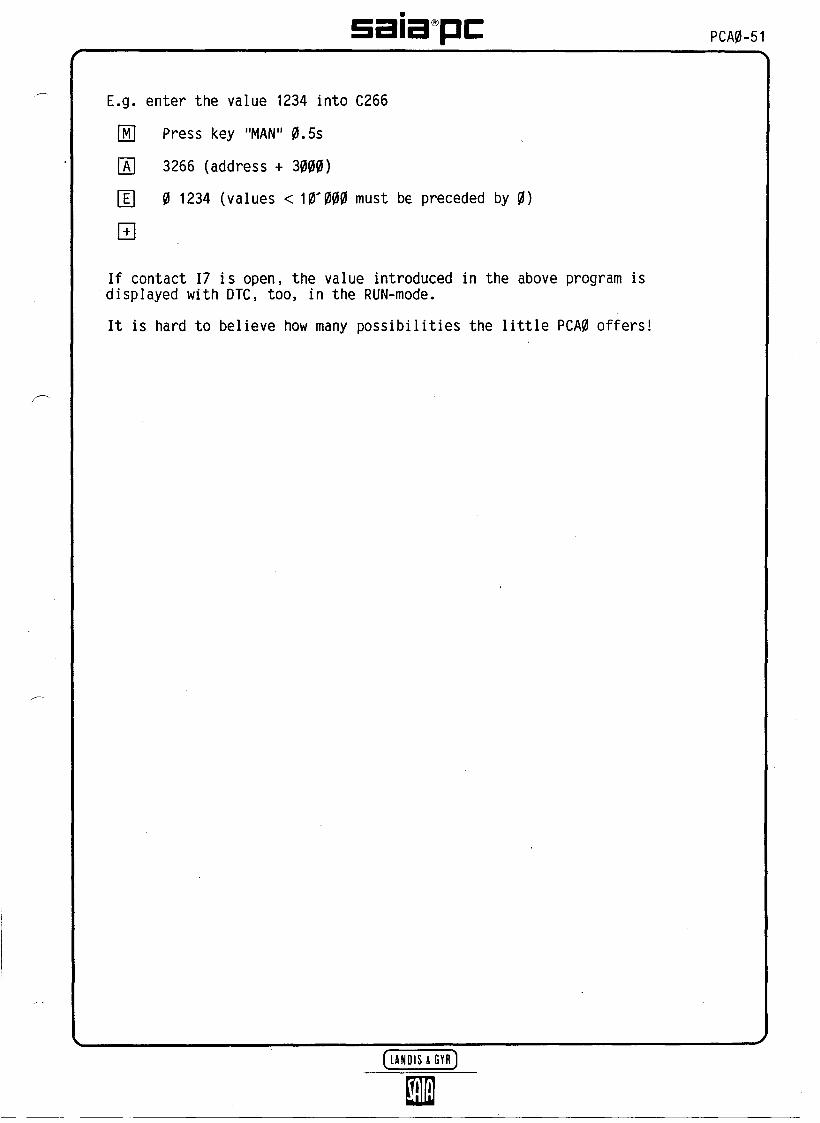
E.g. enter the value 1234 into C266
[M] Press key "MAN" 0.5s
[A] 3266 (address + 3000)
[Ë] 0 1234 (values < 10^000 must be preceded by 0)
If contact 17 is open, the value introduced in the above program isdisplayed with DTC, too, in the RUN-mode.
It is hard to believe how many possibilities the little PCA0 offers!

PCA0-52 satapc(C4) If long jumps are to be programmed
A program consisting of 2047 steps is a long program for a PCA0. But theuser memory has a capacity of 0...4095 steps.
If long jumps with end addresses in the second half of the user memory,i.e. from 2048 to 4095 are to be programmed, these jump instructionsmust be entered using two lines.
This applies to all jump instructions JMP, JIO, JIZ and JMS.
a) Jump instructions with operands 1 to 2047(Operand 0000 is not allowed, see b.)
Example: Conditional jump with end address 1845
either
or
JIO (21) 1845
JIO (21)00
01845
-one line as usual
two lines, with the firstline containing the operand 0
b) Jump instructions with operands 2048 to 4095
Example: Jump to the subroutine 3280
For programming: 501502
JMS (23) 000 3280
For checking: 501502502
JMS (23) 001 1232EE 3280
= convert
The value 01 1232 residing in the user memory corresponds to the jumpaddress 3280. 01 stands for the multiple of 2048 and 1232 is theremainder (1 x 2048 + 1232 = 3280).
With key [C] the actual jump address is displayed, with the codecontaining the character EE (applies to the programming unitPCA2.P05).
In case of a jump instruction with the operand 0 the second line isautomatically read for the end address. Therefore, a jump to theaddress 0 always consists of two lines:
JMP (20)00
00
c) The following is an example using a blinker in a subroutine. Thesubroutine starts at address 3500.Main program
ADDR NC MNC OPRD^500 26 MIL 1501 23 JMS502 00 3500-503 20 JMP 500
Subroutine
ADDR NC MNC OPRD3500 02 STL 2563501 14 STR 2563502 00 23503 13 COO 243504 24 RET 0

satapc PCA0-53
The instruction PAS 18 serves to stop the parallel programs, ifthey are no longer required
Limitation of the assigned parallel programs
All SAIA-PCs allow assignment of up to 16 parallel programs and runningthem in parallel. Up to now it has been necessary to.reassign a PP to adummy program loop if it was no longer required. However, no time couldthus be saved during the execution of the remaining PPs.
In case of the PCA0, however, it is now possible to limit a maximumnumber of active PPs with the PAS 18-instruction.
After the PP-assignment with PAS 0...max. 15 a limited number of PPscan be determined in the user program at any place and as many times asdesired.
1st line
2nd line
Parallel programassignment
x in the range 0...15
PAS
Assigned PP
PP 0. 1. 2. 3. 4. 5. 6. 7. 8. 9. 10. 11. 12. 13. 14. 15.
*) If a higher number than the PPs originally assigned is entered withPAS 18, no malfunction is caused. The inactive PPs 9...11, however,will require processing time in the system program.

PCA0-54 saopc(C6) With the instruction "Check-sum" the reliability of your PCA0 is
considerably increased
PAS 30 and PAS 31...34 "Check Sum" of the system and user program
The "Check Sum" serves to establish the check sum of the memory contentsof system programs (PAS 30) or of user programs or texts (PAS 31...34).Thus, it can be ensured that the contents of the memories checked havenot been changed.
After execution of the instruction:
- ACCU = 1 If the comparison is correct
- ACCU = 0 If the reference value does not comply with the checksum.
The instructions PAS 30...34 are always executed irrespective of the ACCUstate.
If a change in contents has occurred, the user can take the measures whichseem necessary to him: triggering an alarm, resetting the watchdog etc.
PAS00
PAS
XX
300
31..
xxxx
.34
Check sum of the system program2nd line is always 00 0
Check sum of the user program, 31...34 being intro-duced corresponding to the program sections 1K...4K.Reference value
The appropriate reference value for the user program is obtained by exe-cuting the respective PAS-instruction in the operating mode STEP. ThePCA0 displays this check sum on the PCA0 programming unit for a fewseconds. In the operating mode PROG, the corresponding reference value canthen be introduced in the 2nd line of the PAS 31...34 instruction.
Attention: Execution of these instructions takes quite a long time:
PAS 30 = 28.0msPAS 31...34 = 8.3ms
Therefore, use "Check Sum" only if the sequence to be controlled allowsit: e.g. when switching on the PC, at the end of an operation cycle, etc.
It is recommended not to introduce this instruction into the user programuntil it has been completely developed and tested. Each program altera-tion, irrespective of whether the program was extended or reduced,results in an alteration of the "Check Sum".Example: A 2K-user program is to be executed upon switching on
2021
r- 222324
— 25
PAS09
JIZPAS07JIZ
30 r— COO31 '-JMP
—35— 36
SEOJMP
318253532
154035
25530
1635
Ï Check SumJ 1.K
\ Check SumJ 2. K
\ Main program with-* MD-monitoring
\ Set a t arm output/ outside the main
program
Proceed:- After entering and checking theprogram, select operating mode STEP
- Type in ADR 23 +-*-the reference value for 2. K (PAS
32) appears for approx. 20 sec.- Type ADR 24 (+) for input ofreference vaiue in mode PRG
- Same procedure for PAS 31
[LANOtSmYR]n

satapcANLAGE :
Schritt
0
1
23
4
5
6
7
8
9
0
1
2
3
4
56
7
89
0
123
4
5
6
78
9
0
1
23
4
5
6
7
8
9
Mnemo-code
Zahlen-code Operand Kommentar
NOP
SÎH
STL
ANH
ANL
ORH
ORL
XOR
NEG
DYN
OUT
SEO
REO
COO
SIR
SCR
SEI
INC
DEC
SEA
JMP
JIO
JIZ
JMS
REI
WIH
MIL
INI
DEI
PAS
DOP
DTC
Mnem
ocod
e
00
01
02
03
04
05
06
07
08
09
10
11
12
13
14
15
16
17
18
19
20
21
22
23
24
25
26
27
28
29
30
31
Zahl
enco
de
1
1
1
1
1
1
1
01
] Befehl
wird
nur aus-
[ qeführt
wenn
ACCU
=
X
X
X
X
X
X
X
X
X
uu<cN
4)M
^tuCO
X
X
X
X
X
X
X
X
X
X
X
X
X
X
X
X
X
X
X
XACCU w
ird
beeinflusst
Ein-,Ausqänge 0-255Zeitglieder, r,r, 70-,Zähler 256-287Merker 764Haftsoeicher 765 - 999^
SODECO-SAtA AG CH-32W MUHTEN SCHWEtZ[tAMiStEYRJ


saia pc
-
ANLAGE:
Schritt.
00123456789101234567892012345678930123456789401234567a9
1nemo-code
Zahlencode )perartd Kommentar
Logik-Befehle
i --<!SL 'S
0- 1C0 )-z tn
r*t.
= jWtn
M\tm
z*t
j15L
]Z^
u13.
i:ceO
^15
etc
r^ is
ceoX
00L
L3LJZ
o\13.
Z>-O
Aktions-Befehle
L
t—^O
,
C3LJÖl
c-
0LJce
M^
0ot-i
-?
o:tn
U s
ceün
SODECO-SAtA AG CH 2M MUHTEN SCHWEtZ
\o
UJUl
r-
uz
30 O\
-i -t_J UJ^ 01
[UMOtS
Schritt
5012345678960123456789701234567898012345678990123456789
Inemo-code
Zahlen-code
Sprung-Befehle
ts
O-ïi!*1
^ CM
O !--!
<*] "*i
tMH)
Eiitj]
f
L:
"< <t-J CN
n i—: bj*) ce
tnC-Q
3:3
oc
i
3
Operand Kommentar
Hilfs-Befehle
r-CM
z
oct
L-C
! O\CM
< Ln^ -ti Q-
IS
G-OO
^
LJ
O
EingängeAusqanqe ^Zeitglieder 756-287ZählerMerker 288-764
Haftspeicher 765-999 j


SAIAAGCH-3280 Murten SwitzerlandIndustrial Components and Controls
Betgique Landis & Gyr Belge SA, Dépt. IndustrieAvenue des anciens combattants 190, B-1140 Bruxelles3* 02/2440211,1x65930
Denmark E.Friis-MikkelsenA/SKrogsh0jvej 51, DK-2880 Bagsvaerd'S' 02/986333,1x37350
Deutschiand Landis & Gyr GmbHFriesstrasse 20-24, Postfach 600529, D-6000 Frankfurt 60S' 069/40020,1x0417164
Espana Landis & Gyr BC SABatalla del Salado 25, Apartado 575, Madrid 7S 91/4671900.1x22976
France AcirSàrl29-31, rue de Naples, F-75008 Paris'S* 1/7823795,1x630680
Great Britain Landis & Gyr LtdElgee Works, Victoria Road, North Acton, London W3 6XS'S* 01/9925311,1x21486
ttatia Landis & Gyr SpA, Divisione CommercialeVia P. Rondoni 1,1-20146 MilanoS 02/4248,1x332142
Nedertand Landis & Gyr BV, Div. ElectrowaterKampenringweg 45, Postbus 444, NL-2800 AK-GoudaS 01820-65432,1x20657
Norge MaltheWinje&CoA/SCort Adelers gate 14, Postboks 2440, Solli, N-0202 Oslo 2S 02/56 59 90, Tx 19629
Österreich Landis & Gyr Gesellschaft m. b. HBreitenfurterStrasse 148a, Postfach 9, A-1230 Wien^ 0222/84 26 26-0, Tx 132 706
Schweiz Saia AG, Verkauf SchweizCH-3280 MurtenS 037/721185,1x942127
Suomi OY Landis & Gyr ABFinntand SF-02430 Masala
'S (90) 29731, Tx 121 037
Sverige Beving Elektronik ABBox 21104, S-10031 StockholmIB* 08/151780, Tx 10040
Austratia Landis & Gyr (Australia) Pty Ltd411 Ferntree Gully Road, P.O. Box 202, MountWaverley, Vie. 3149T 3/544-2322, Tx 32 224
Printed in Switzerland 26/79 E2 3.87 H07 Subject to change without notice