manufacturer’s declaration dichiarazione del … · manufacturer’s declaration dichiarazione...
TRANSCRIPT
1N.B.: The company reserves the right to make modifications - N.B.: Con riserva di modifiche - N.B.: Sous réserve de modification
MANUFACTURER’S DECLARATIONDICHIARAZIONE DEL FABBRICANTEDECLARATION DU FABRICANT
The Undersigned PRESSMAIR SRL, Via Miari 3/C, 41034 Finale Emilia, Modena, Italy, declares under its own responsability that ALL PRODUCTS AND COMPONENTS illu-strated in this Catalogue and therein described, are intended to be incorporated into a machinery subject to the application of the 89/392/CEE Directive and subsequent amendments apply.Commissioning of the component or system shall be forbidden until the machinery, into the component is to be incorporated, is declared to comply with the EEC directive.
Ing. Rodolfo Musci Managing Director
La Sottoscritta PRESSMAIR SRL, Via Miari 3/C, 41034 Finale Emilia, Modena, Italia, dichiara sotto la propria responsabilità che TUTTI I PRODOTTI E I COMPONENTI illustra-ti sul presente catalogo ed in esso descritti, sono destinati ad essere incorporati in mac-chine a cui si applica la Direttiva 89/392/CEE e suoi successivi emendamenti.La messa in funzione del componente o del sistema è vietata prima che la macchina in cui verrà incorporato venga dichiarata conforme alle disposizioni della direttiva.
Ing. Rodolfo Musci Amministratore Delegato
La Soussignée PRESSMAIR SRL, Via Miari 3/C, 41034 Finale Emilia, Modena, Italie, déclare sous sa propre responsabilité que TOUS LES PRODUITS ET LES COMPOSANTS compris et illustrés dans ce Catalogue, sont destinés á être incorporés dans une machine á laquelle s’applique la Directive 89/392/CEE et ses amendements successifs.La mise en fonction du composant ou système est interdite tant que la machine dans laquelle le composant ou système doit être incorporé n’aura pas été déclarée conforme à la directive.
Ing. Rodolfo Musci Administrateur
2 N.B.: The company reserves the right to make modifications - N.B.: Con riserva di modifiche - N.B.: Sous réserve de modification
MAINTENANCE AND OPERATING INSTRUCTIONSISTRUZIONI DI USO E MANUTENZIONEINSTRUCTIONS D’EMPLOI ET D’ENTRETIEN
GENERAL MAINTENANCE AND OPERATING INSTRUCTIONSWARNINGSThe need and frequency of maintenance operations will substantially depend on the operating conditions. High temperatures, ozone concentration and moisture (see tropical regions), will damage quickly all rubber parts. When operating in dusty envi-ronments, all valves reliefs, compressor case recesses and lubrication points need proper protection. Before adding any oil, clean accurately the input area to avoid inside pollution. We suggest to disassemble the apparatus (when necessary) only in clean and dust-free area. Maintenance and/or repair works will be mainly of two types:A) Standard maintenance operations performed by service personnel. Includes all daily, weekly or monthly maintenance: it
mainly includes checks of devices and pipeworks to eliminate leaks and verify correct setting. Any malfunctions should be immediately eliminated.
B) Special maintenance operations performed by skilled personnel. Devices must be disassembled and cleaned, defective components replaced, springs checked and if necessary, replaced. Use AGIP OSO - 35 oil or equivalent when reassembling components. Before reinstallation, check operation and set-up. A general check of the complete installation should be per-formed before putting the device into operation.
INSTALLATION: Cylinders can work in any position. Pipes delivering air to cylinders should be fed from below, to remove any condensate. To prevent rod flexing, it is basic to ensure a correct cylinder alignement. When cylinder installation is of oscilla-ting type, pressure and stroke should remain within the prescribed limits, to avoid excessive stress on the rod. Cylinders must be firmly connected to the frame, taking account of the operating pressure. When cylinders work in dusty environments, rod should be chromium-plated or protected by a bellow.
LUBRICANTS AND MEDIUM: Please use only clean or dry air, lubricated with AGIP OSO - 35 or equivalent.
ISTRUZIONI DI USO E MANUTENZIONE
GENERALITÀGli interventi di manutenzione dipendono principalmente dalla severità delle condizioni di lavoro. Occorre tener presente che nelle aree geografiche con condizioni atmosferiche di temperatura e di umidità molto elevate, si determina un invecchiamento più rapido di tutte le parti in gomma. Nei luoghi molto polverosi, è necessario proteggere opportunamente sia gli scarichi delle valvole che i raccordi di immissione del lubrificante. Quando è necessario aggiungere il lubrificante, prestare molta attenzione al fine di evitare l’inavvertita immissione di materiale inquinante (polvere od altro) unitamente all’olio. È opportuno che le operazioni di manutenzione che comporta-no lo smontaggio del componente, siano effettuate in ambienti privi di polvere. Gli interventi di manutenzione sono principalmente di due tipi:A) Manutenzione standard, giornaliera, settimanale o mensile. Consiste essenzialmente nel controllo delle apparecchiature e delle
tubazioni, per la verifica delle tenute e la messa a punto del funzionamento. Tutti i difetti rilevati devono essere eliminati immediata-mente.
B) Manutenzione periodica svolta da personale specializzato. Gli apparecchi devono essere smontati e puliti, ed i componenti usurati o difettosi sostituiti, le molle verificate e se necessario sostituite. Rimontare i componenti utilizzando lubrificante AGIP OSO - 35 o equivalente. Verificare il funzionamento ed effettuare le necessarie regolazioni. Prima di procedere alla messa in marcia dell’impian-to, effettuare un controllo generale ed una prova di funzionamento completa.
INSTALLAZIONE: I cilindri possono lavorare in ogni posizione, tuttavia è buona norma alimentarli dalla parte inferiore al fine di facilita-re l’evacuazione della eventuale condensa. Evitare spinte trasversali sullo stelo, facendo molta attenzione al corretto allineamento del cilindro. Quando la applicazione del cilindro è del tipo oscillante, la pressione e la corsa devono rimanere entro i limiti indicati, al fine di evitare un eccessivo stress allo stelo. I cilindri devono essere saldamente collegati alla struttura di supporto, in relazione alla loro pressio-ne di lavoro. Quando i cilindri lavorano in un ambiente polveroso, usare steli cromati oppure proteggere gli steli con opportuni soffietti.
LUBRIFICANTI E TIPO DI ARIA UTILIZZABILE: Utilizzare aria filtrata, lubrificata con olio AGIP OSO - 35 o equivalente, o secca.
INSTRUCTIONS D’EMPLOI ET D’ENTRETIEN
AVERTISSEMENTSLa nécessité et la fréquence des travaux d’entretien ou des réparations dépendent des conditions de travail.Dans les régions où les températures et les taux d’humidité sont élevés, il se vérifie un vieillissement prémature des parties en caou- tchouc.Pour les applications en milieu poussièreux, les échappements des distributeurs, les ouvertures des carters des compresseurs et les points de lubrification doivent être protégés. Il est conseillé, pour le démontage des appareils, d’operer dans un local dépourvu de poussière.Il existe deux types d’entretien:A) l’entretien effectué par le personnel de service: il peut être journalier, hebdomadaire ou mensuel et consiste principalement à vérifier
le bon fonctionnement des appareils, en éliminant immédiatement tout défaut éventuellement relevé.B) l’entretien effectué par le personnel spécialisé: il consiste à démonter et à nettoyer tous les appareils. Tous les éléments usagés ou
défectueux doivent être remplacés. Utiliser un lubrifiant pour le remontage des appareils. Vérifier le bon fonctionnement de chaque dispositif et faire les réglages nécessaires. Ensuite, effectuer un essai complet de l’installation afin de vérifier son bon fonctionne-ment.
INSTALLATION: Les vérins peuvent travailler dans toutes les positions. Dans la mesure du possible, il est préférable que l’alimentation se passe par le bas afin de faciliter l’évacuation de l’eau de condensation. Il est indispensable de s’assurer de l’alignement correct des vérins de façon qu’aucune charge de flexion ne s’exerce sur la tige. Quand la fixation du vérin est de type oscillant, la course et la pres-sion doivent rester dans des limites acceptables, pour limiter les efforts sur la tige.Fixer les vérins en fonction de la pression et de la charge maximum d’exercice. Dans un environnement très poussièreux la tige doit être chromée ou protégée par un soufflet spécial.
LUBRIFICATION ET TyPE D’AIR: Utiliser de l’air propre, sec ou lubrifié, avec huile AGIP OSO 32 ou équivalente.
3
MAINTENANCE AND OPERATING INSTRUCTIONSISTRUZIONI DI USO E MANUTENZIONEINSTRUCTIONS D’EMPLOI ET D’ENTRETIEN
N.B.: The company reserves the right to make modifications - N.B.: Con riserva di modifiche - N.B.: Sous réserve de modification
MAGNETIC SWITCHES FOR MICROCYLINDERS AND TIE ROD CYLINDERSTIPS FOR A CORRECT APPLICATION
Please always refer to the instructions attached to each magnetic switch supplied.Before wiring the switch ensure that the load is connected in series and that the voltage, power and current never exceed the rated values indicated. Since the switch leads behave as a capacity load, the service life of a switch is inversely proportional to the length of the cable. If the wiring connection is longer than 20 mt., it is necessary to install a protection system in order to extend the life of the switch.Remember: a programmable logic control generates a resistive load; a long cable generates a capacity load; solenoids, relays, motors, etc., generate an inductive load. If you have to connect inductive loads, keep a safety margin of at least 30% with respect to the maximum admissible current and power.Switches incorporating LED’s generate a voltage drop of 2 to 3 V. At 24 V do not connect more than 2 switches of this type in series. For a passage detection, allow a maximum piston speed of 2 mt./sec.
INTERRUTTORI MAGNETICI PER MICROCILINDRI E CILINDRI A TIRANTICONSIGLI PER UNA CORRETTA APPLICAZIONE
Fare sempre riferimento al foglio di istruzioni allegato a ciascun interruttore consegnato.Prima di collegare l’interruttore, assicurarsi che il carico sia connesso in serie, e che i valori di cor-rente e di tensione non superino mai i valori nominali indicati. Poiché i cavi si comportano come un carico capacitivo, e quindi la durata della vita di un interruttore è inversamente proporzionale alla lunghezza del cavo; per migliorare le prestazioni, è necessario montare un circuito di protezione ogni volta che la lunghezza dei cavi supera i 20 mt. Ricordarsi che: un controllo logico programma-bile genera un carico resistivo; un lungo cavo genera un carico capacitivo; solenoidi, valvole, moto-ri, relay, ecc. generano un carico induttivo. Se dovete collegare un carico induttivo, mantenete un margine del 30% rispetto alla massima corrente e potenza indicata. I LED incorporati negli interrut-tori, generano una caduta di tensione di 2 o 3 Volt. Lavorando 24 V non collegare in serie più di 2 interruttori di questo tipo. Per un rilevamento al passaggio, il pistone non deve superare la velocità di 2 mt./sec.
CAPTEURS MAGNETIQUES POUR MICROVERINS ET VERINS A TIRANTSCONSEILS D’UTILISATION
Réferez-Vous toujours aux instructions annexes à chaque capteur livré.Avant de brancher l’interrupteur, s’assurer qu’une charge électrique soit reliée en série, et que les valeurs de courant, de tension et de puissance maximale commutable ne soient pas supérieures aux valeurs nominales indiquées. Les câbles se comportent comme une charge capacitive, par conséquent la durée de la vie d’un interrupteur est inversement proportionelle à la longueur du câble. Pour améliorer les performances, il faut monter en série un système de protection pour des distances supérieures a 20 mt.Rappelez-vous: un contrôle logique programmable produit une charge résistive; un câble long pro-duit une charge capacitive; un solénoïde, une valve, un relais, un moteur produisent une charge inductive.Dans le cas de branchement avec relais ou électrovalves, maintenir une marge de sécurité de 30% minimum par rapport au courant et à la puissance maximum indiqués.À cause des LED, le branchement en série provoque une chute de tension de 2 à 3 V. Il est con-seillé au maximum 2 interrupteurs en série pour une tension de 24 V.Pour une détection au passage, la vitesse du piston ne doit jamais dépasser 2 mt./sec.
4 N.B.: The company reserves the right to make modifications - N.B.: Con riserva di modifiche - N.B.: Sous réserve de modification 4
PRESSMAIR POLICY FOR CONFORMITY CERTIFICATION CONCERNING THE EEC DIRECTIVE 94/9/CE (ATEX) FOR PNEUMATIC AND HYDRAULIC PRODUCTS.
Annex VIII of the EEC Directive 94/9/CE (ATEX) allows the producer perform a Self-Certification of the produced equipment, but only in some specific cases and if only items meet the regulation for the declared application field; the self-certification can be issued only following a specific procedure clearly indicated by the Annex VIII of the Directive. So we decided the following policy:
1. Pressmair srl will not issue a certification for the whole production line using an external Certification Agency, because the cost of this opera-tion would be uselessly expensive compared with the real market necessities.
2. If one of our Customer will ask us an ATEX certification, we will act as follow:• We will send to our customer, who should ask for it in advance, the Electrical Components Certification (Pressmair does not produce such com-
ponents even if installed as accessories on our products); our supplier of Electrical Components will provide such Certification.• We will perform the self-certification procedure provided by the EEC Directive for all those mechanical items (cylinders and valves) directly pro-
duced by Pressmair srl, and we will send to our Customers the pertinent Conformity Certificate issued following Annex VIII of the EEC Directive 94/9/CE
3. To issue the Conformity Certificate we will ask our Customers to contribute to the Documentation Management fees paying a small cost; this is done because the Directive compels us to build up a special technical file to be preserved under our responsibility for not less than 10 years. Customers will be informed about the amount of the cost under request.
Renazzo li, 01/02/2004 PRESSMAIR SRL Ing. Rodolfo Musci Managing Director
LA POLITICA PRESSMAIR DI CERTIFICAZIONE DI CONFORMITA’ ALLA DIRETTIVA CEE 94/9/CE (ATEX) PER LE APPARECCHIATURE PNEUMATICHE ED IDRAULICHE.
L’allegato VIII della direttiva CEE 94/9/CE (ATEX) riconosce al produttore la facoltà di autocertificare in casi ben specifici le apparecchiature prodotte, purché esse soddisfino alla normativa per il campo di applicazione dichiarato; tale autocertificazione deve essere eseguita secondo una procedura chiaramente indi-cata nel citato allegato VIII della direttiva.Abbiamo perciò deciso quanto segue:
1 La Soc. Pressmair srl non procede alla certificazione globale di tutta la propria produzione a mezzo di un Ente Certificatore esterno, in quanto ritiene inutilmente onerosa una tale operazione, in rapporto alle effettive necessità del mercato.
2 In caso di richiesta di certificazione ATEX da parte dei ns. clienti, opereremo come segue:• trasferiremo ai clienti, che ce ne avessero fatto richiesta preventiva, la certificazione delle apparecchiature elettriche (che non sono mai di produzione
Pressmair, anche se eventualmente montate come accessori di ns. prodotti), che a ns. volta avremo ricevuto dai ns. fornitori. • Effettueremo la procedura di autocertificazione prevista dalla normativa per tutte le apparecchiature meccaniche di ns. produzione, (cilindri e valvole) e
trasmetteremo ai ns. clienti i relativi Certificati di Conformità emesso secondo l’allegato VIII della normativa.3 Per la emissione del Certificato di Conformità sarà richiesto ai clienti il pagamento dei costi di gestione della documentazione, in quanto la normativa pre-
vede la costituzione presso i ns. uffici di un dossier tecnico da conservare per 10 anni a disposizione per eventuali ispezioni; tale costo di gestione verrà comunicato a richiesta del cliente.
Renazzo li, 01/02/2004 PRESSMAIR SRL Ing. Rodolfo Musci Amm. Delegato
POLITIQUE PRESSMAIR CONCERNANTE LA CERTIFICATION DE CONFORMITEE A’ LA DIRECTIVE CEE/94/9/CE (ATEX) POUR LES PRODUITS PNEUMATIQUES ET HyDRAULIQUE
L’annexe VIII de la directive CEE 94/9/CE (ATEX) reconnaisse au producteur la possibilitée de auto-certifier les appareils produits, à condition qu’ils soient conformes à la normative, en cas specifiques et suivant une procédure bien claire.La sociétée Pressmair srl a pourtant décidé que:
1 Nous n’irons pas à la certification totale de toute notre production de verins et distributeurs par un Organisme extérieur de Certification, parce que nous estimons inutilement onéreux une telle operation, comparée aux effectives nécessitées du marché.
2 Dans le cas que un client nous demande la certification ATEX pour un de nos produits à cause d’une effective nécessitée, nous irons agir comme ici indi-qué :
• Nous enverrons aux clients, qui nous l’aurons demandé préalablement, la certifications des appareils électriques (qui ne sont jamais de production Pressmair, bien que eventuelment installés comme composants accessoires de nos produits) ; nous aurons reçu par nos fournissuers telle certification concernante les composants électriques.
• Nous irons émettre l’auto-certification prévue par la normative pour tous les appareils mécaniques de notre production (verins et distributeurs), et nous enverrons aux clients le Certificat de Conformitée édité suivant l’annexe VIII de la normative CEE/94/9CE.
3 Pour l’émission des Certificat de Conformitéee les clients seront chargés des coûts de gestion de la documentation, parce que la normative nous oblige à créer un dossier technique chez notre boureau, et à le mantenir à disposition pour eventuelles inspections pour 10 années ; tel coût sera comuniqué sur demande.
Renazzo, 01/02/2004 PRESSMAIR SRL Ing. Rodolfo Musci Administrateur
5
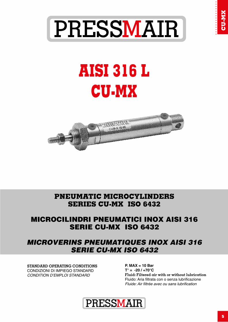
AISI 316 LCU-MX
STANDARD OPERATING CONDITIONSCONDIZIONI DI IMPIEGO STANDARDCONDITION D’EMPLOI STANDARD
P. MAX = 10 BarT° = -20 / +70°CFluid: Filtered air with or without lubricationFluido: Aria filtrata con o senza lubrificazioneFluide: Air filtrée avec ou sans lubrification
CU
-MX
PNEUMATIC MICROCYLINDERSSERIES CU-MX ISO 6432
MICROCILINDRI PNEUMATICI INOX AISI 316SERIE CU-MX ISO 6432
MICROVERINS PNEUMATIQUES INOX AISI 316SERIE CU-MX ISO 6432
CETOP RP 52 P - ISO 6432 AISI 316 L
6 N.B.: The company reserves the right to make modifications - N.B.: Con riserva di modifiche - N.B.: Sous réserve de modification
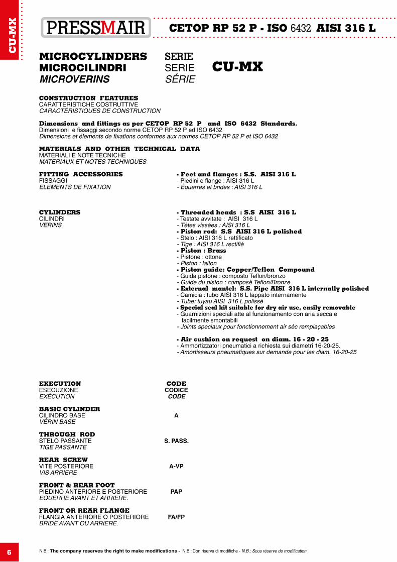
MICROCYLINDERS SERIE MICROCILINDRI SERIE CU-MX MICROVERINS SÉRIE
CONSTRUCTION FEATURES CARATTERISTICHE COSTRUTTIVE CARACTÉRISTIQUES DE CONSTRUCTION
Dimensions and fittings as per CETOP RP 52 P and ISO 6432 Standards.Dimensioni e fissaggi secondo norme CETOP RP 52 P ed ISO 6432Dimensions et élements de fixations conformes aux normes CETOP RP 52 P et ISO 6432
MATERIALS AND OTHER TECHNICAL DATA MATERIALI E NOTE TECNICHEMATERIAUX ET NOTES TECHNIQUES
FITTING ACCESSORIES - Feet and flanges : S.S. AISI 316 LFISSAGGI - Piedini e flange : AISI 316 LELEMENTS DE FIXATION - Équerres et brides : AISI 316 L
CYLINDERS - Threaded heads : S.S AISI 316 LCILINDRI - Testate avvitate : AISI 316 LVERINS - Têtes vissées : AISI 316 L - Piston rod: S.S AISI 316 L polished - Stelo : AISI 316 L rettificato - Tige : AISI 316 L rectifié - Piston : Brass - Pistone : ottone - Piston : laiton - Piston guide: Copper/Teflon Compound - Guida pistone : composto Teflon/bronzo - Guide du piston : composé Teflon/Bronze - External mantel: S.S. Pipe AISI 316 L internally polished - Camicia : tubo AISI 316 L lappato internamente - Tube: tuyau AISI 316 L polissé - Special seal kit suitable for dry air use, easily removable - Guarnizioni speciali atte al funzionamento con aria secca e facilmente smontabili - Joints speciaux pour fonctionnement air séc remplaçables - Air cushion on request on diam. 16 - 20 - 25 - Ammortizzatori pneumatici a richiesta sui diametri 16-20-25. - Amortisseurs pneumatiques sur demande pour les diam. 16-20-25
EXECUTION CODEESECUZIONE CODICEEXÉCUTION CODE
BASIC CYLINDER CILINDRO BASE A VÉRIN BASE THROUGH RODSTELO PASSANTE S. PASS. TIGE PASSANTE
REAR SCREWVITE POSTERIORE A-VPVIS ARRIERE
FRONT & REAR FOOTPIEDINO ANTERIORE E POSTERIORE PAPEQUERRE AVANT ET ARRIERE.
FRONT OR REAR FLANGEFLANGIA ANTERIORE O POSTERIORE FA/FPBRIDE AVANT OU ARRIERE.
CU
-MX
CETOP RP 52 P - ISO 6432 AISI 316 L
7N.B.: The company reserves the right to make modifications - N.B.: Con riserva di modifiche - N.B.: Sous réserve de modification
MICROCYLINDERS SERIEMICROCILINDRI SERIE “CU-MX”MICROVERINS SERIE
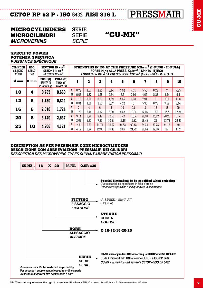
DESCRIPTION AS PER PRESSMAIR CODE MICROCYLINDERS DESCRIZIONE CON ABBREVIAZIONI PRESSMAIR DEI CILINDRI DESCRIPTION DES MICROVERINS TyPES SUIVANT ABBREVIATION PRESSMAIR
CU-MX 16 X 20 PA-PNL Q.SP. =30-
CU-MX microcylinders UNI according to CETOP and ISO DP 6432CU-MX microcilindri UNI a Norme CETOP e ISO DP 6432CU-MX microvérins UNI suivants CETOP et ISO DP 6432
Ø 10-12-16-20-25BOREALESAGGIOALESAGE
STROKECORSACOURSE
FITTINGFISSAGGIOFIXATIONS
Special dimensions to be specified when orderingQuote speciali da specificare in fase d’ordineDimensions speciales à indiquer avec la commande
(A-S.PASS.); (A); (P-AP)(FP); (FA).
Accessories - To be ordered separatelyPer accessori supplementari eseguire ordine a parteAccessoires: doivent être commandés à part
SPECIFIC POWER POTENZA SPECIFICA PUISSANCE SPÉCIFIQUE
STRENGTHS IN KG AT THE PRESSURE KG/cm2 (I=PUSH - II=PULL)FORZE IN Kg ALLA PRESS. Kg/cm2 (I SPINTA - II TIRO)
FORCES EN KG Á LA PRESSION DE KG/cm2 (I=POUSSÉE - II= TRAIT)
SECTION IN cm2SEZIONE IN cm2SECTION IN cm2
CYLINDERCILINDRO
VÉRIN
Ø mm
ROD STELOTIGE
Ø mm PUSH (I)SPINTA (I)
POUSSÉE (I)
PULL (II)TIRO (II)TRAIT (II)
1 2 3 4 5 6 7 8 9 10
10
12
16
20
25
4
6
6
8
10
0,785
1,130
2,010
3,140
4,906
0,660
0,844
1,724
2,637
4,121
0,780,661,130,84
21,723,142,634,94,12
1,571,322,261,69
43,446,285,279,818,24
2,351,983,392,53
65,179,427,9114,7112,36
3,142,644,523,37
86,8912,5610,5419,6216,48
3,923,35,654,2210
8,6215,713,1824,5320,6
4,713,966,78
512
10,3418,8415,8229,4324,72
5,504,627,915,9014
12,0621,9818,4534,3428,84
6,285,28
96,7516
13,825,12
2139,2532,96
75,9410,17,5918
15,528,2623,7344,15
37
7,856,611,38,4420
17,2431,426,37
4941,2
IIIIIIIIIIIIIII
SERIESERIESERIE
CU
-MX
CETOP RP 52 P - ISO 6432 AISI 316 L
8N.B.: The company reserves the right to make modifications - N.B.: Con riserva di modifiche - N.B.: Sous réserve de modification
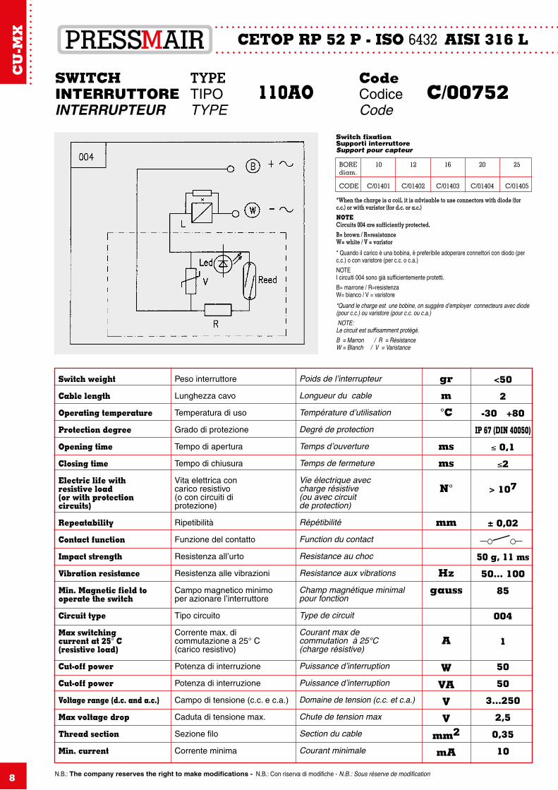
SWITCH TYPE CodeINTERRUTTORE TIPO 110AO Codice C/00752INTERRUPTEUR TYPE Code
Poids de l’interrupteur
Longueur du cable
Température d’utilisation
Degré de protection
Temps d’ouverture
Temps de fermeture
Vie électrique aveccharge résistive(ou avec circuitde protection)
Répétibilité
Function du contact
Resistance au choc
Resistance aux vibrations
Champ magnétique minimalpour fonction
Type de circuit
Courant max decommutation à 25°C(charge résistive)
Puissance d’interruption
Puissance d’interruption
Domaine de tension (c.c. et c.a.)
Chute de tension max
Section du cable
Courant minimale
gr
m
°C
ms
ms
N°
mm
Hz
gauss
A
W
VA
V
V
mm2
mA
<50
2
-30 +80
IP 67 (DIN 40050)
≤ 0,1
≤2
> 107
± 0,02
50 g, 11 ms
50... 100
85
004
1
50
50
3...250
2,5
0,35
10
Switch weight
Cable length
Operating temperature
Protection degree
Opening time
Closing time
Electric life withresistive load(or with protectioncircuits)
Repeatability
Contact function
Impact strength
Vibration resistance
Min. Magnetic field to operate the switch
Circuit type
Max switchingcurrent at 25° C(resistive load)
Cut-off power
Cut-off power
Voltage range (d.c. and a.c.)
Max voltage drop
Thread section
Min. current
Peso interruttore
Lunghezza cavo
Temperatura di uso
Grado di protezione
Tempo di apertura
Tempo di chiusura
Vita elettrica concarico resistivo(o con circuiti diprotezione)
Ripetibilità
Funzione del contatto
Resistenza all’urto
Resistenza alle vibrazioni
Campo magnetico minimoper azionare l’interruttore
Tipo circuito
Corrente max. dicommutazione a 25° C(carico resistivo)
Potenza di interruzione
Potenza di interruzione
Campo di tensione (c.c. e c.a.)
Caduta di tensione max.
Sezione filo
Corrente minima
*When the charge is a coil, it is advisable to use connectors with diode (for c.c.) or with varistor (for d.c. or a.c.)NOTECircuits 004 are sufficiently protected.B= brown / R=resistanceW= white / V = varistor
* Quando il carico è una bobina, è preferibile adoperare connettori con diodo (per c.c.) o con varistore (per c.c. o c.a.)
NOTEI circuiti 004 sono già sufficientemente protetti.
B= marrone / R=resistenzaW= bianco / V = varistore
*Quand le charge est une bobine, on suggère d’employer connecteurs avec diode (pour c.c.) ou varistore (pour c.c. ou c.a.) NOTE:Le circuit est suffisamment protégé.B = Marron / R = RésistanceW = Blanch / V = Varistance
Switch fixationSupporti interruttoreSupport pour capteur
BORE 10 12 16 20 25diam.
CODE C/01401 C/01402 C/01403 C/01404 C/01405
8
CU
-MX
9
CETOP RP 52 P - ISO 6432 AISI 316 L
9 N.B.: The company reserves the right to make modifications - N.B.: Con riserva di modifiche - N.B.: Sous réserve de modification
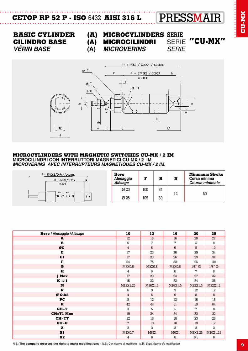
BASIC CYLINDER (A) MICROCYLINDERS SERIECILINDRO BASE (A) MICROCILINDRI SERIE “CU-MX” VÉRIN BASE (A) MICROVERINS SERIE
MICROCYLINDERS WITH MAGNETIC SWITCHES CU-MX / 2 IMMICROCILINDRI CON INTERRUTTORI MAGNETICI CU-MX / 2 IMMICROVERINS AVEC INTERRUPTEURS MAGNETIQUES CU-MX / 2 IM.
Bore Minumum StrokeAlesaggio F R N Corsa minimaAlésage Course minimale
Ø 20 100 64 12 50 Ø 25 109 69
Bore / Alesaggio /Alésage 10 12 16 20 25 A 12 16 16 20 22 B 6 7 7 5 8 ØC 4 6 6 8 10 E 17 23 26 29 34 E1 17 23 26 29 34 F 64 75 82 95 104 G M5X0.8 M5X0.8 M5X0.8 1/8” G 1/8” G H 4 6 6 7 8 J Max 17 20 24 27 32 K +/-1 16 22 22 24 28 M M12X1.25 M16X1.5 M16X1.5 M22X1.5 M22X1.5 N 6 9 9 12 12 Ø O-h8 4 6 6 8 8 PC 8 12 12 16 16 R 42 44 51 59 64 CH=T 3 5 5 7 8 CH=T1 Max 19 24 24 32 32 CH=TT 12 16 18 23 26 CH=U 7 10 10 13 17 Z 3 3 3 3 3 X1 M4X0.7 M6X1 M6X1 M8X1.25 M10X1.25 X2 4 6 6 6.5 6
CU
-MX
10
CETOP RP 52 P - ISO 6432 AISI 316 L
N.B.: The company reserves the right to make modifications - N.B.: Con riserva di modifiche - N.B.: Sous réserve de modification
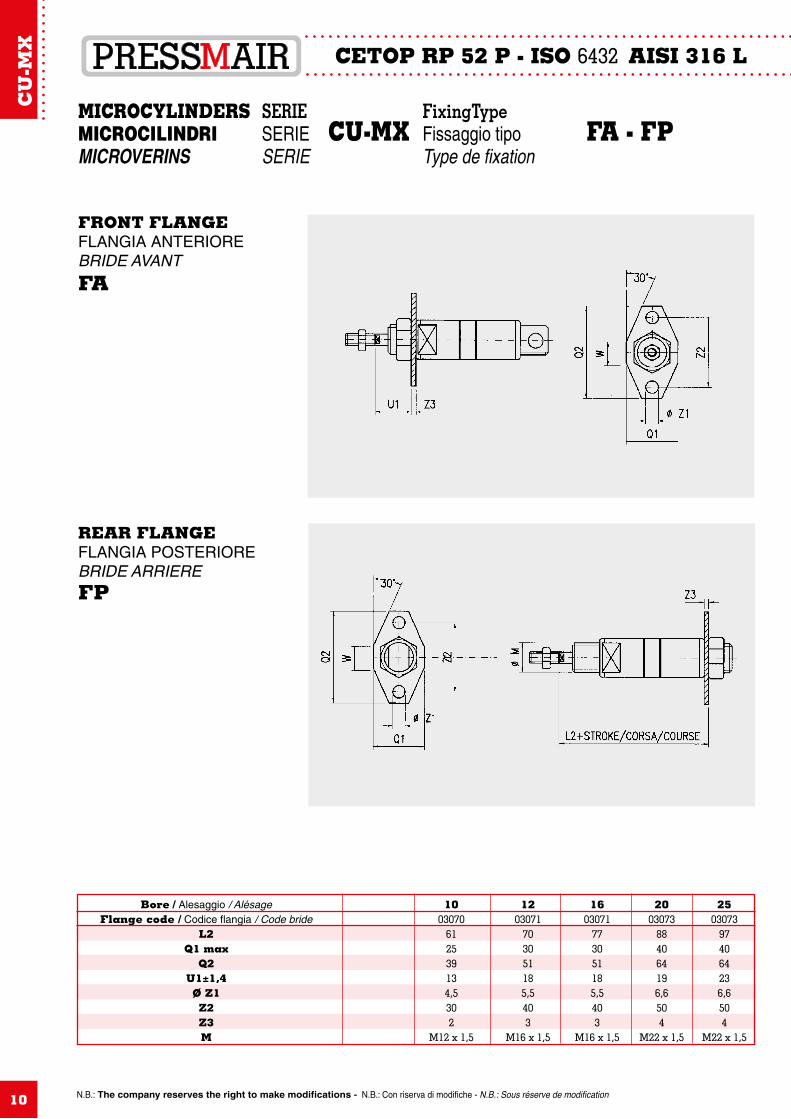
MICROCYLINDERS SERIE FixingTypeMICROCILINDRI SERIE CU-MX Fissaggio tipo FA - FPMICROVERINS SERIE Type de fixation
Bore / Alesaggio / Alésage 10 12 16 20 25 Flange code / Codice flangia / Code bride 03070 03071 03071 03073 03073 L2 61 70 77 88 97 Q1 max 25 30 30 40 40 Q2 39 51 51 64 64 U1±1,4 13 18 18 19 23 Ø Z1 4,5 5,5 5,5 6,6 6,6 Z2 30 40 40 50 50 Z3 2 3 3 4 4 M M12 x 1,5 M16 x 1,5 M16 x 1,5 M22 x 1,5 M22 x 1,5
FRONT FLANGEFLANGIA ANTERIOREBRIDE AVANTFA
REAR FLANGEFLANGIA POSTERIOREBRIDE ARRIEREFP
CU
-MX
N.B.: The company reserves the right to make modifications - N.B.: Con riserva di modifiche - N.B.: Sous réserve de modification 11
CETOP RP 52 P - ISO 6432 AISI 316 L
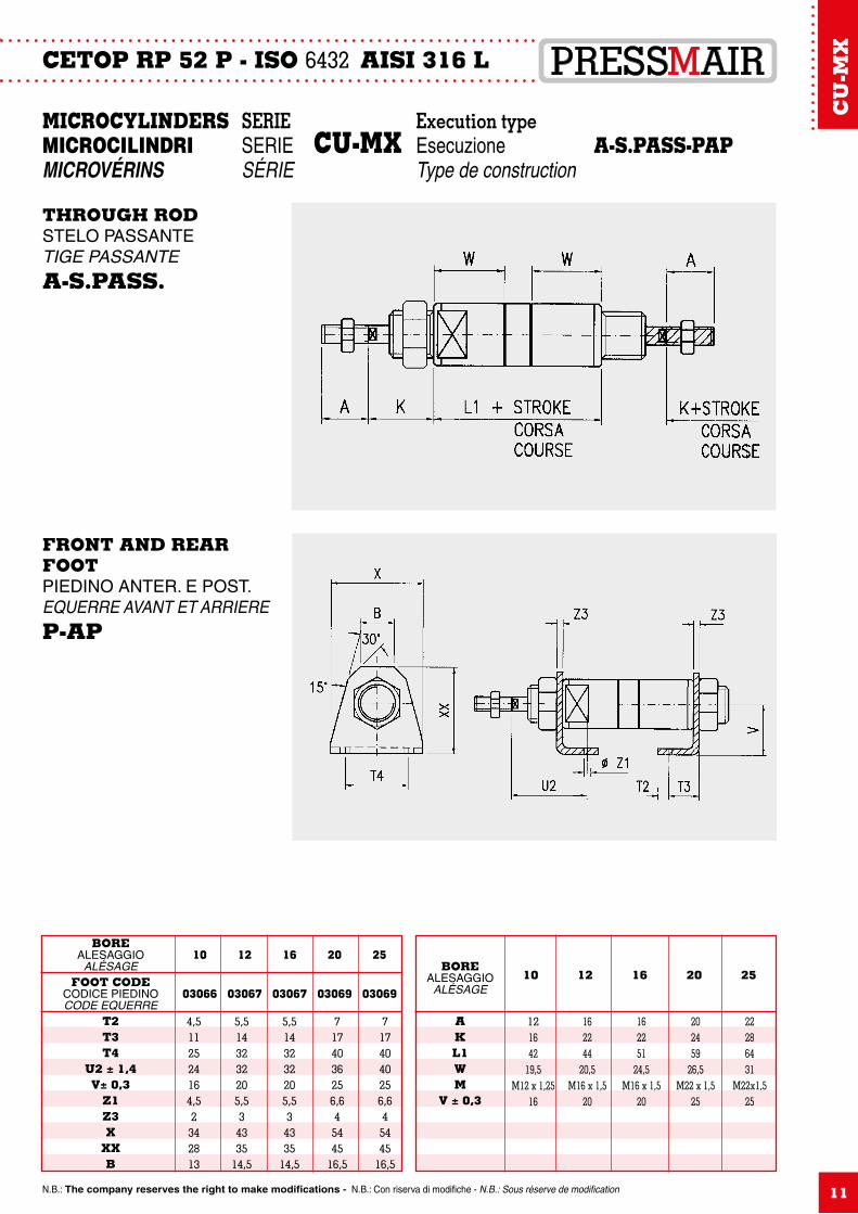
MICROCYLINDERS SERIE Execution type MICROCILINDRI SERIE CU-MX Esecuzione A-S.PASS-PAPMICROVÉRINS SÉRIE Type de construction
BOREALESAGGIO
ALÉSAGEFOOT CODE
CODICE PIEDINOCODE EQUERRE
T2T3T4
U2 ± 1,4V± 0,3
Z1Z3X
XXB
10
03066
12
03067
16
03067
20
03069
25
03069
THROUGH RODSTELO PASSANTE TIGE PASSANTEA-S.PASS.
FRONT AND REAR FOOTPIEDINO ANTER. E POST.EQUERRE AVANT ET ARRIEREP-AP
4,5112524164,52342813
5,5143232205,534335
14,5
5,5143232205,534335
14,5
7174036256,645445
16,5
7174040256,645445
16,5
BOREALESAGGIO
ALÉSAGE
AKL1WM
V ± 0,3
10 12 16 20 25
121642
19,5M12 x 1,25
16
162244
20,5M16 x 1,5
20
162251
24,5M16 x 1,5
20
202459
26,5M22 x 1,5
25
22286431
M22x1,525
CU
-MX
N.B.: The company reserves the right to make modifications - N.B.: Con riserva di modifiche - N.B.: Sous réserve de modification12
CETOP RP 52 P - ISO 6432 AISI 316 L
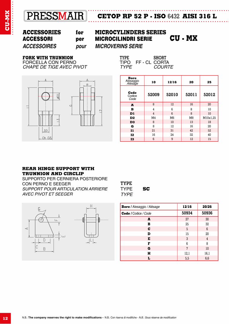
ACCESSORIES for MICROCYLINDERS SERIESACCESSORI per MICROCILINDRI SERIE CU - MXACCESSOIRES pour MICROVERINS SERIE
FORK WITH TRUNNION TYPE SHORTFORCELLA CON PERNO TIPO FF - CL CORTACHAPE DE TIGE AVEC PIVOT TYPE COURTE
Bore / Alesaggio / Alésage 12/16 20/26
Code / Codice / Code 50934 50936 A 27 30 B 25 32 C 5 6 D 15 20 E 3 4 F 6 8 G 7 10 H 12,1 16,1 L 5,5 6,6
REAR HINGE SUPPORT WITHTRUNNION AND CIRCLIPSUPPORTO PER CERNIERA POSTERIORECON PERNO E SEEGERSUPPORT POUR ARTICULATION ARRIEREAVEC PIVOT ET SEEGER
BoreAlesaggioAlésage
CodeCodice Code
AB
D1D2D3GI1I2I3
TYPETYPE SCTYPE
10 12/16 20 25
52009 52010 52011 52012
8 12 16 20
4 6 8 10 4 6 8 10 M4 M6 M8 M10x1,25 8 10 13 18 8 12 16 20 21 31 42 52 16 24 32 40 6 9 12 15
CU
-MX
13
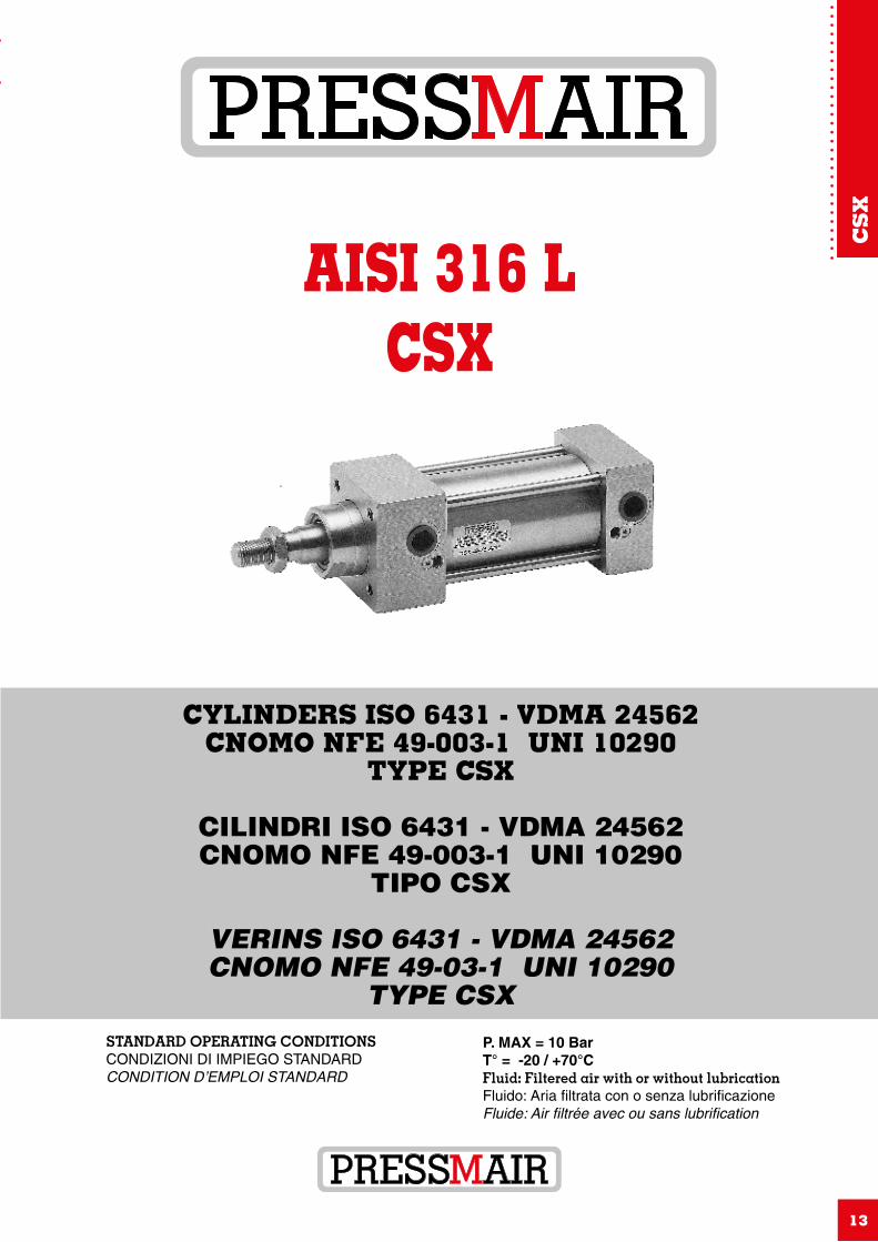
CYLINDERS ISO 6431 - VDMA 24562CNOMO NFE 49-003-1 UNI 10290
TYPE CSX
CILINDRI ISO 6431 - VDMA 24562CNOMO NFE 49-003-1 UNI 10290
TIPO CSX
VERINS ISO 6431 - VDMA 24562CNOMO NFE 49-03-1 UNI 10290
TYPE CSX
AISI 316 LCSX
STANDARD OPERATING CONDITIONSCONDIZIONI DI IMPIEGO STANDARDCONDITION D’EMPLOI STANDARD
P. MAX = 10 BarT° = -20 / +70°CFluid: Filtered air with or without lubricationFluido: Aria filtrata con o senza lubrificazioneFluide: Air filtrée avec ou sans lubrification
CS
X
ISO 6431 - VDMA CNOMO UNI AISI 316 L
N.B.: The company reserves the right to make modifications - N.B.: Con riserva di modifiche - N.B.: Sous réserve de modification14
MATERIALS AND TECHNICAL FEATURESMATERIALI IMPIEGATI E NOTE TECNICHE CSXMATERIAUX ET CARACTERISTIQUES TECHNIQUES
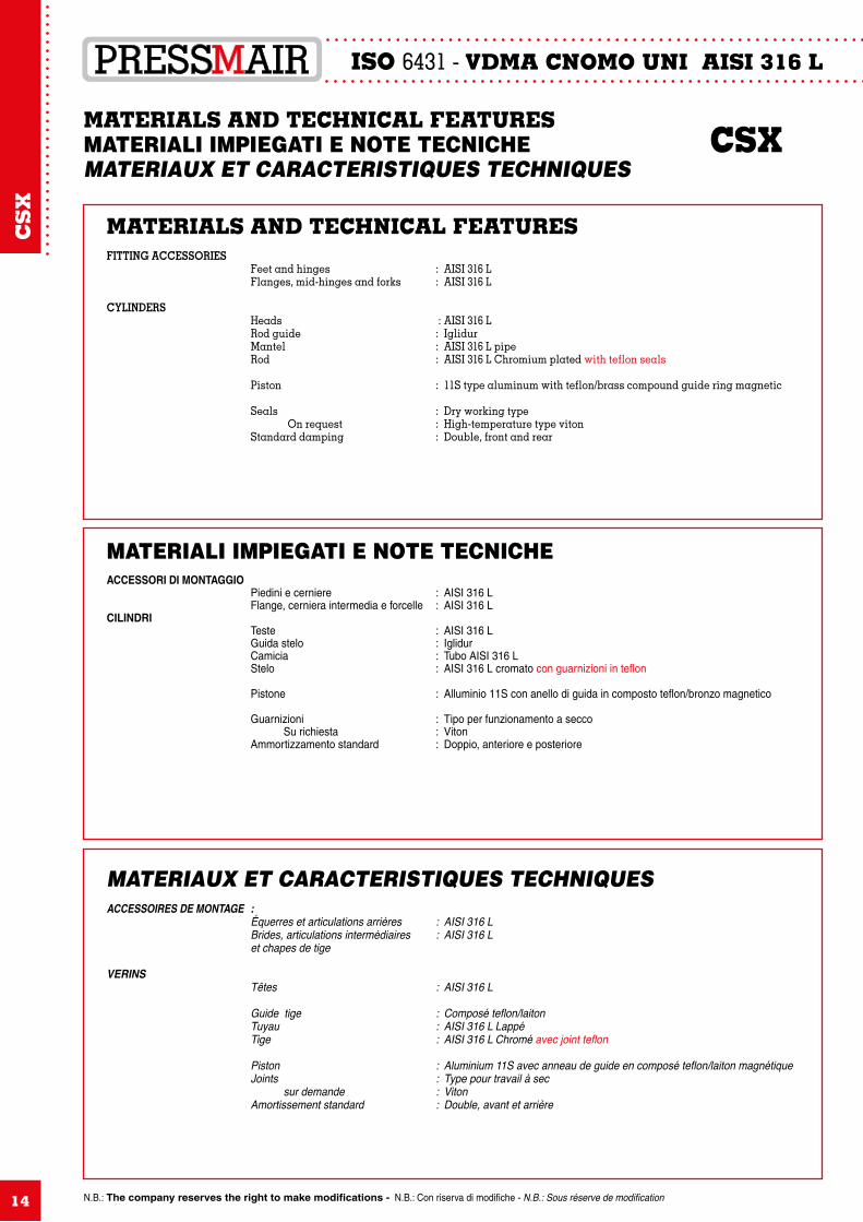
MATERIALS AND TECHNICAL FEATURESFITTING ACCESSORIES Feet and hinges : AISI 316 L Flanges, mid-hinges and forks : AISI 316 L
CYLINDERS Heads : AISI 316 L Rod guide : Iglidur Mantel : AISI 316 L pipe Rod : AISI 316 L Chromium plated with teflon seals
Piston : 11S type aluminum with teflon/brass compound guide ring magnetic Seals : Dry working type On request : High-temperature type viton Standard damping : Double, front and rear
MATERIALI IMPIEGATI E NOTE TECNICHEACCESSORI DI MONTAGGIO Piedini e cerniere : AISI 316 L Flange, cerniera intermedia e forcelle : AISI 316 LCILINDRI Teste : AISI 316 L Guida stelo : Iglidur Camicia : Tubo AISI 316 L Stelo : AISI 316 L cromato con guarnizioni in teflon
Pistone : Alluminio 11S con anello di guida in composto teflon/bronzo magnetico
Guarnizioni : Tipo per funzionamento a secco Su richiesta : Viton Ammortizzamento standard : Doppio, anteriore e posteriore
MATERIAUX ET CARACTERISTIQUES TECHNIQUESACCESSOIRES DE MONTAGE : Équerres et articulations arrières : AISI 316 L Brides, articulations intermédiaires : AISI 316 L et chapes de tige
VERINS Têtes : AISI 316 L
Guide tige : Composé teflon/laiton Tuyau : AISI 316 L Lappé Tige : AISI 316 L Chromé avec joint teflon
Piston : Aluminium 11S avec anneau de guide en composé teflon/laiton magnétique Joints : Type pour travail à sec sur demande : Viton Amortissement standard : Double, avant et arrière
CS
X
N.B.: The company reserves the right to make modifications - N.B.: Con riserva di modifiche - N.B.: Sous réserve de modification
ISO 6431 - VDMA CNOMO UNI AISI 316 L
15
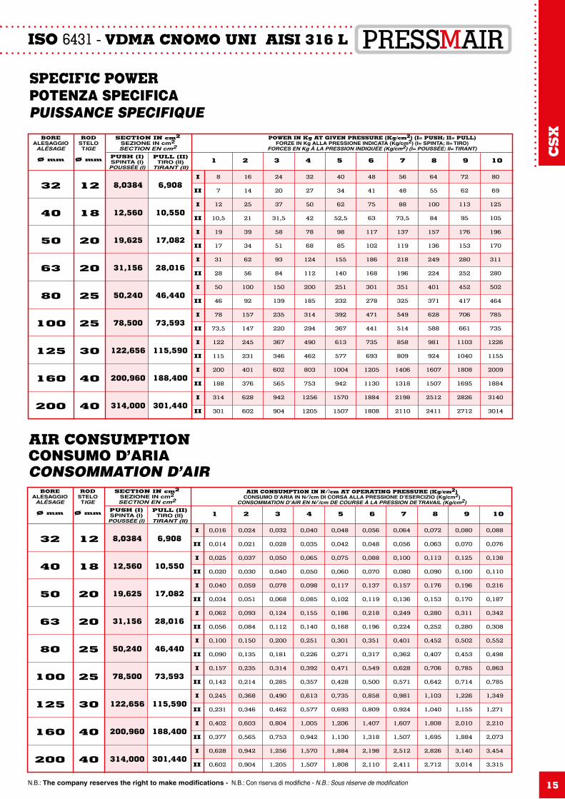
AIR CONSUMPTION IN Nl /cm AT OPERATING PRESSURE (Kg/cm2)CONSUMO D’ARIA IN Nl /cm DI CORSA ALLA PRESSIONE D’ESERCIZIO (Kg/cm2)
CONSOMMATION D’AIR EN Nl /cm DE COURSE À LA PRESSION DE TRAVAIL (Kg/cm2)
SECTION IN cm2SEZIONE IN cm2SECTION EN cm2
BOREALESAGGIO
ALÉSAGE
Ø mm
RODSTELOTIGE
Ø mm PUSH (I)SPINTA (I)
POUSSÉE (I)
PULL (II)TIRO (II)
TIRANT (II)1 2 3 4 5 6 7 8 9 10
32
40
50
63
80
100
125
160
200
12
18
20
20
25
25
30
40
40
8,0384
12,560
19,625
31,156
50,240
78,500
122,656
200,960
314,000
6,908
10,550
17,082
28,016
46,440
73,593
115,590
188,400
301,440
I
II
I
II
I
II
I
II
I
II
I
II
I
II
I
II
I
II
0,016
0,014
0,025
0,020
0,040
0,034
0,062
0,056
0,100
0,090
0,157
0,142
0,245
0,231
0,402
0,377
0,628
0,602
0,024
0,021
0,037
0,030
0,059
0,051
0,093
0,084
0,150
0,135
0,235
0,214
0,368
0,346
0,603
0,565
0,942
0,904
0,032
0,028
0,050
0,040
0,078
0,068
0,124
0,112
0,200
0,181
0,314
0,285
0,490
0,462
0,804
0,753
1,256
1,205
0,040
0,035
0,065
0,050
0,098
0,085
0,155
0,140
0,251
0,226
0,392
0,357
0,613
0,577
1,005
0,942
1,570
1,507
0,048
0,042
0,075
0,060
0,117
0,102
0,186
0,168
0,301
0,271
0,471
0,428
0,735
0,693
1,206
1,130
1,884
1,808
0,056
0,048
0,088
0,070
0,137
0,119
0,218
0,196
0,351
0,317
0,549
0,500
0,858
0,809
1,407
1,318
2,198
2,110
0,064
0,056
0,100
0,080
0,157
0,136
0,249
0,224
0,401
0,362
0,628
0,571
0,981
0,924
1,607
1,507
2,512
2,411
0,072
0,063
0,113
0,090
0,176
0,153
0,280
0,252
0,452
0,407
0,706
0,642
1,103
1,040
1,808
1,695
2,826
2,712
0,080
0,070
0,125
0,100
0,196
0,170
0,311
0,280
0,502
0,453
0,785
0,714
1,226
1,155
2,010
1,884
3,140
3,014
0,088
0,076
0,138
0,110
0,216
0,187
0,342
0,308
0,552
0,498
0,863
0,785
1,349
1,271
2,210
2,073
3,454
3,315
SPECIFIC POWERPOTENZA SPECIFICAPUISSANCE SPECIFIQUE
POWER IN Kg AT GIVEN PRESSURE (Kg/cm2) (I= PUSH; II= PULL)FORZE IN Kg ALLA PRESSIONE INDICATA (Kg/cm2) (I= SPINTA; II= TIRO)
FORCES EN Kg À LA PRESSION INDIQUÉE (Kg/cm2) (I= POUSSÉE; II= TIRANT)
SECTION IN cm2SEZIONE IN cm2SECTION EN cm2
BOREALESAGGIO
ALÉSAGE
Ø mm
RODSTELOTIGE
Ø mm PUSH (I)SPINTA (I)
POUSSÉE (I)
PULL (II)TIRO (II)
TIRANT (II)1 2 3 4 5 6 7 8 9 10
32
40
50
63
80
100
125
160
200
12
18
20
20
25
25
30
40
40
8,0384
12,560
19,625
31,156
50,240
78,500
122,656
200,960
314,000
6,908
10,550
17,082
28,016
46,440
73,593
115,590
188,400
301,440
I
II
I
II
I
II
I
II
I
II
I
II
I
II
I
II
I
II
8
7
12
10,5
19
17
31
28
50
46
78
73,5
122
115
200
188
314
301
16
14
25
21
39
34
62
56
100
92
157
147
245
231
401
376
628
602
24
20
37
31,5
58
51
93
84
150
139
235
220
367
346
602
565
942
904
32
27
50
42
78
68
124
112
200
185
314
294
490
462
803
753
1256
1205
40
34
62
52,5
98
85
155
140
251
232
392
367
613
577
1004
942
1570
1507
48
41
75
63
117
102
186
168
301
278
471
441
735
693
1205
1130
1884
1808
56
48
88
73,5
137
119
218
196
351
325
549
514
858
809
1406
1318
2198
2110
64
55
100
84
157
136
249
224
401
371
628
588
981
924
1607
1507
2512
2411
72
62
113
95
176
153
280
252
452
417
706
661
1103
1040
1808
1695
2826
2712
80
69
125
105
196
170
311
280
502
464
785
735
1226
1155
2009
1884
3140
3014
AIR CONSUMPTIONCONSUMO D’ARIACONSOMMATION D’AIR
CS
X
ISO 6431 - VDMA CNOMO UNI AISI 316 L
N.B.: The company reserves the right to make modifications - N.B.: Con riserva di modifiche - N.B.: Sous réserve de modification16
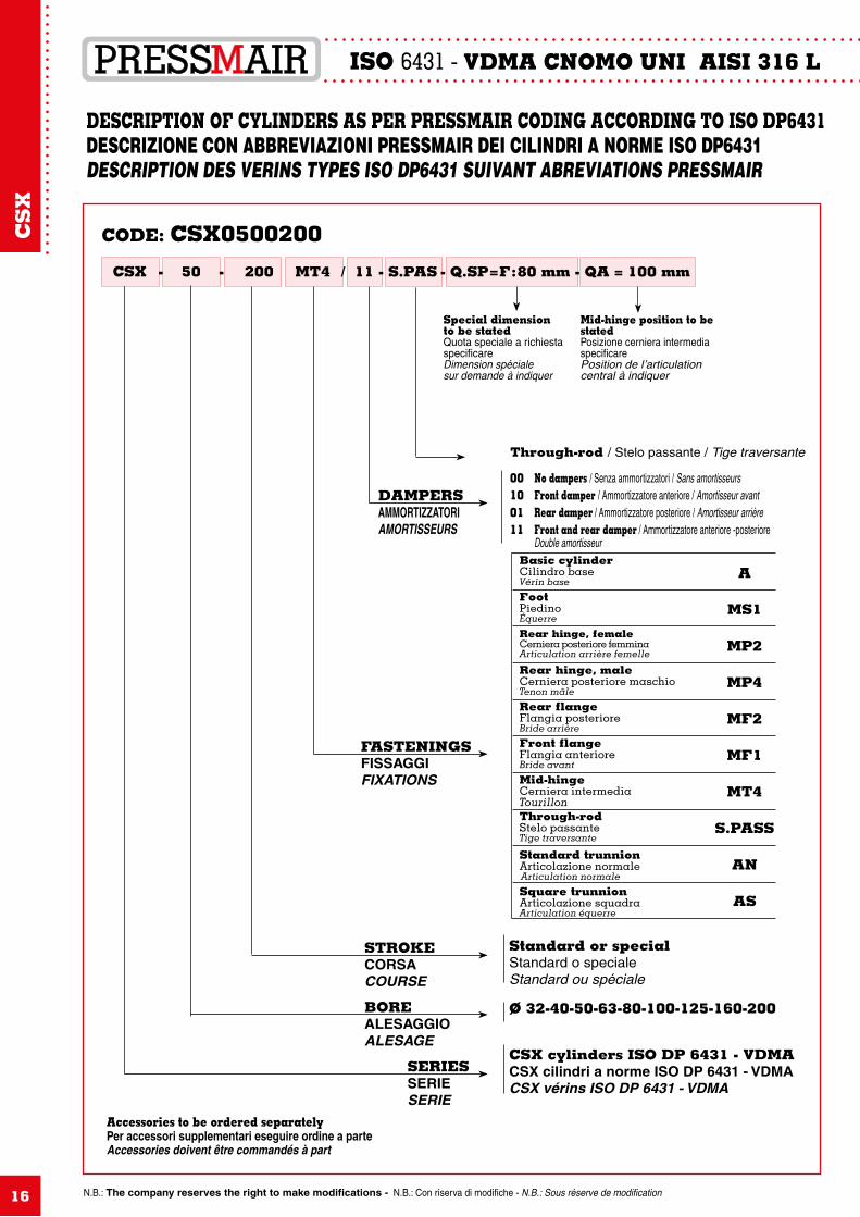
DESCRIPTION OF CYLINDERS AS PER PRESSMAIR CODING ACCORDING TO ISO DP6431DESCRIZIONE CON ABBREVIAZIONI PRESSMAIR DEI CILINDRI A NORME ISO DP6431DESCRIPTION DES VERINS TYPES ISO DP6431 SUIVANT ABREVIATIONS PRESSMAIR
CODE: CSX0500200
CSX 50 - 200- MT4 / 11 - S.PAS - Q.SP = F : 80 mm - QA = 100 mm
Accessories to be ordered separatelyPer accessori supplementari eseguire ordine a parteAccessories doivent être commandés à part
SERIESSERIESERIE
CSX cylinders ISO DP 6431 - VDMACSX cilindri a norme ISO DP 6431 - VDMACSX vérins ISO DP 6431 - VDMA
BOREALESAGGIOALESAGE
STROKECORSACOURSE
FASTENINGSFISSAGGIFIXATIONS
DAMPERSAMMORTIZZATORIAMORTISSEURS
Standard or specialStandard o specialeStandard ou spéciale
Basic cylinderCilindro baseVérin base
FootPiedinoÉquerre
Rear hinge, femaleCerniera posteriore femminaArticulation arrière femelle
Rear hinge, maleCerniera posteriore maschioTenon mâle
Rear flangeFlangia posterioreBride arrière
Front flangeFlangia anterioreBride avant
Mid-hingeCerniera intermediaTourillonThrough-rodStelo passanteTige traversante
Standard trunnionArticolazione normaleArticulation normale
Square trunnionArticolazione squadraArticulation équerre
A
MS1
MP2
MP4
MF2
MF1
MT4
S.PASS
AN
AS
00100111
Through-rod / Stelo passante / Tige traversante
Special dimensionto be statedQuota speciale a richiestaspecificareDimension spécialesur demande à indiquer
Mid-hinge position to be statedPosizione cerniera intermedia specificarePosition de l’articulation central à indiquer
No dampers / Senza ammortizzatori / Sans amortisseursFront damper / Ammortizzatore anteriore / Amortisseur avantRear damper / Ammortizzatore posteriore / Amortisseur arrièreFront and rear damper / Ammortizzatore anteriore -posterioreDouble amortisseur
Ø 32-40-50-63-80-100-125-160-200
CS
X
N.B.: The company reserves the right to make modifications - N.B.: Con riserva di modifiche - N.B.: Sous réserve de modification
ISO 6431 - VDMA CNOMO UNI AISI 316 L
17
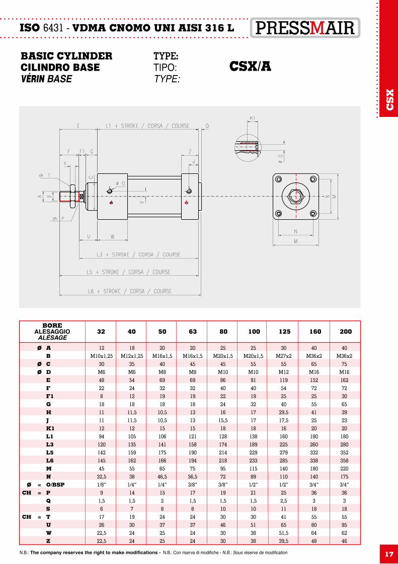
BASIC CYLINDER TYPE: CILINDRO BASE TIPO: CSX/A VÉRIN BASE TYPE:
12M10x1,25
30M648228181111129412014214545
32,51/8”
91,561726
22,522,5
Ø A B Ø C Ø D E F F1 G H J K1 L1 L3 L5 L6 M N Ø = O/BSP CH = P Q S CH = T U W Z
18M12x1,25
35M654241218
11,511,5121051351591625538
1/4”141,5719302424
20M16x1,5
40M869321918
10,510,51510614117516665
46,51/4”152824372525
20M16x1,5
45M86932191813131512115819019475
56,53/8”171,5824372424
25M20x1,5
45M108640222416
15,5181281742142189572
3/8”191,51030463030
25M20x1,5
55M109140193217171813818922923311589
1/2”211,51030513838
30M27x2
55M12119542540
29,517,5161602252792851401101/2”252,5114165
51,539,5
40M36x2
65M161527225554125201802603323381801403/4”3631855806448
40M36x2
75M161627230653923201802803523582201753/4”3631855956246
BOREALESAGGIO
ALÉSAGE32 40 50 63 80 100 125 160 200
CS
X
ISO 6431 - VDMA CNOMO UNI AISI 316 L
N.B.: The company reserves the right to make modifications - N.B.: Con riserva di modifiche - N.B.: Sous réserve de modification18
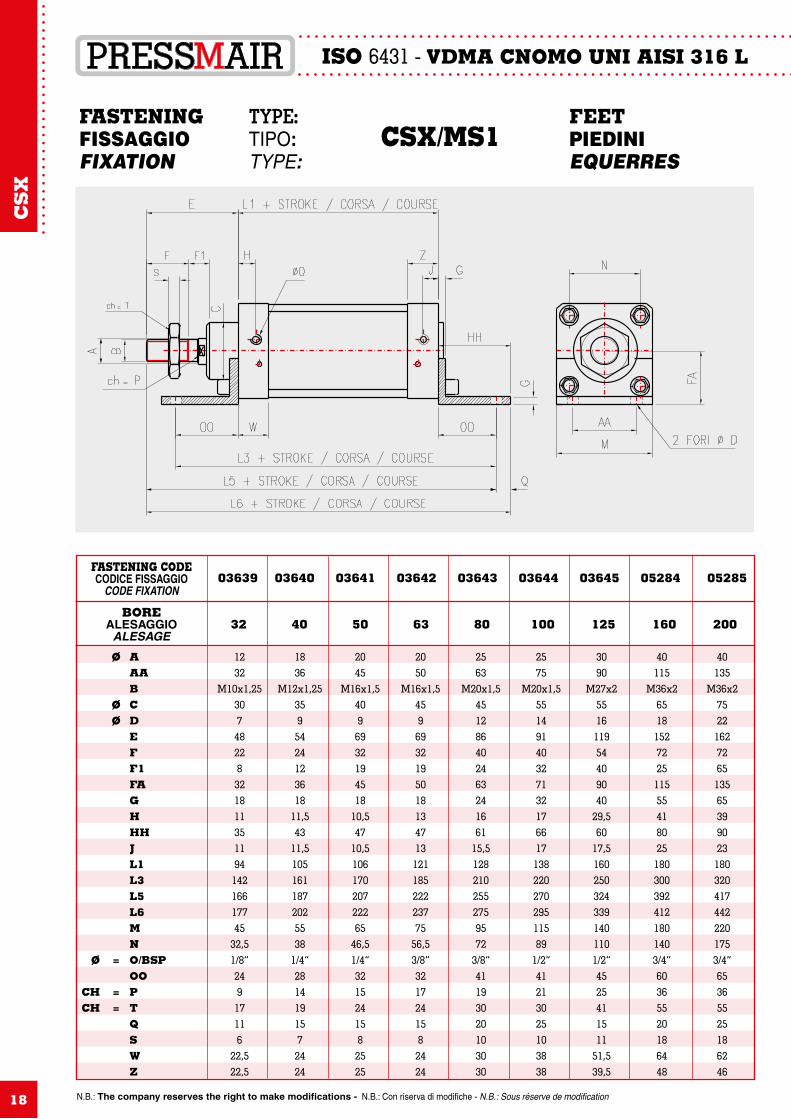
FASTENING TYPE: FEETFISSAGGIO TIPO: CSX/MS1 PIEDINIFIXATION TYPE: EQUERRES
1232
M10x1,253074822832181135119414216617745
32,51/8”24917116
22,522,5
Ø A AA B Ø C Ø D E F F1 FA G H HH J L1 L3 L5 L6 M N Ø = O/BSP OO CH = P CH = T Q S W Z
1836
M12x1,253595424123618
11,543
11,51051611872025538
1/4”2814191572424
2045
M16x1,54096932194518
10,547
10,510617020722265
46,51/4”3215241582525
2050
M16x1,5459693219501813471312118522223775
56,53/8”3217241582424
2563
M20x1,5451286402463241661
15,51282102552759572
3/8”41193020103030
2575
M20x1,55514914032713217661713822027029511589
1/2”41213025103838
3090
M27x2551611954409040
29,560
17,51602503243391401101/2”4525411511
51,539,5
40115
M36x265181527225115554180251803003924121801403/4”60365520186448
40135
M36x275221627265135653990231803204174422201753/4”65365525186246
BOREALESAGGIO
ALESAGE
FASTENING CODECODICE FISSAGGIO
CODE FIXATION
32 40 50 63 80 100 125 160 200
03639 03640 03641 03642 03643 03644 03645 05284 05285
CS
X
N.B.: The company reserves the right to make modifications - N.B.: Con riserva di modifiche - N.B.: Sous réserve de modification 19
ISO 6431 - VDMA CNOMO UNI AISI 316 L
12M10x1,25
30451026M648228223318121111941421531751/8”
917
32,562645
22,522,5
Ø A B Ø C CL Ø CK (H9) CM Ø D E F F1 FL FA G G1 H J L1 L3 L5 L6 Ø = O/BSP CH = P CH = T RC S U UH W Z
16M12x1,25
35521228M654241225381815
11,511,51051601731971/4”141938730552424
18M16x1,5
40601232M869321927401815
10,510,51061701832151/4”1524
46,5837652525
20M16x1,5
45701640M86932193249182013131211902072393/8”1724
56,5837752424
22M20x1,5
45901650
M108640243653242016
15,51282102272673/8”1930721046953030
25M20x1,5
551102060
M109140324162322517171382302512911/2”21308910511153838
30M27x2
551302570
M12119544050764030
29,517,51602753013551/2”2541110116514051,539,5
40M36x2
651703090
M1615272255590553541251803153504223/4”365514018801806448
40M36x2
751703090
M1616272655590653539231803353704423/4”365517518952206246
BOREALESAGGIO
ALESAGE
FASTENING CODECODICE FISSAGGIO
CODE FIXATION
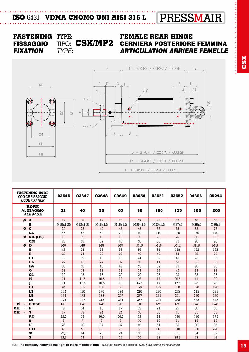
32 40 50 63 80 100 125 160 200
03646 03647 03648 03649 03650 03651 03652 04806 05294
FASTENING TYPE: FEMALE REAR HINGEFISSAGGIO TIPO: CSX/MP2 CERNIERA POSTERIORE FEMMINAFIXATION TYPE: ARTICULATION ARRIERE FEMELLE
CS
X
ISO 6431 - VDMA CNOMO UNI AISI 316 L
N.B.: The company reserves the right to make modifications - N.B.: Con riserva di modifiche - N.B.: Sous réserve de modification20
12M10x1,25
301026M648228223318101111941421531751/8”
932,5
6172645
22,522,5
Ø A B Ø C Ø CK CM Ø D E F F1 FL FA G G1 H J L1 L3 L5 L6 Ø = O/BSP CH = P RC S CH = T U UH W Z
18M12x1,25
351228M654241225381810
11,511,51051601731971/4”143871930552424
20M16x1,5
401232M869321927401812
10,510,51061701832151/4”15
46,582437652525
20M16x1,5
451640M86932193249181213131211902072393/8”17
56,582437752424
25M20x1,5
451650
M108640243653241616
15,51282102272673/8”1972103046953030
25M20x1,5
552060
M109140324162321617171382302512911/2”21891030511153838
30M27x2
552570
M12119544050764020
29,517,51602753013551/2”2511011416514051,539,5
40M36x2
653090
M1615272255590552041251803153504223/4”361401855801806448
40M36x2
753090
M1616272655590652039231803353704423/4”361751855952206246
BOREALESAGGIO
ALESAGE
FASTENING CODECODICE FISSAGGIO
CODE FIXATION
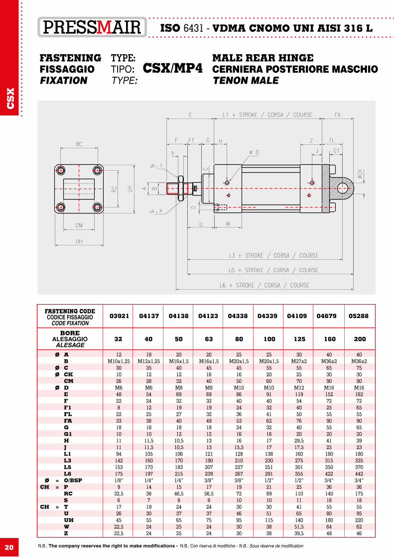
32 40 50 63 80 100 125 160 200
03921 04137 04138 04123 04338 04339 04109 04679 05288
FASTENING TYPE: MALE REAR HINGEFISSAGGIO TIPO: CSX/MP4 CERNIERA POSTERIORE MASCHIOFIXATION TYPE: TENON MALE
CS
X
N.B.: The company reserves the right to make modifications - N.B.: Con riserva di modifiche - N.B.: Sous réserve de modification
ISO 6431 - VDMA CNOMO UNI AISI 316 L
21
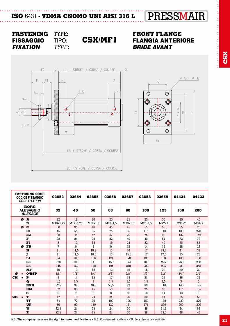
12M10x1,25
304538228711119412014510
1/8”9
1,532,5326176480
22,522,5
Ø A B Ø C E1 E2 F F1 Ø FB H J L1 L3 L6 MF Ø = O/BSP CH = P Q RXR RM S CH = T TF UF W Z
18M12x1,25
35554424129
11,511,510513516210
1/4”141,5383671972902424
20M16x1,5
40655732199
10,510,510614117812
1/4”152
46,545824901102525
20M16x1,5
45755732199131312115819412
3/8”171,556,5508241001202424
25M20x1,5
45957040241216
15,512817421816
3/8”191,5726310301261513030
25M20x1,5
5511575403214171713818923316
1/2”211,5897510301501783838
30M27x2
5514099544016
29,517,516022528520
1/2”252,511090114118022051,539,5
40M36x2
65180132722518412518026033820
3/4”363
14011518552302606448
40M36x2
75220142726522392318028035820
3/4”363
17513518552703006246
BOREALESAGGIO
ALESAGE
FASTENING CODECODICE FISSAGGIO
CODE FIXATION
32 40 50 63 80 100 125 160 200
03653 03654 03655 03656 03657 03658 03659 04434 04433
FASTENING TYPE: FRONT FLANGEFISSAGGIO TIPO: CSX/MF1 FLANGIA ANTERIOREFIXATION TYPE: BRIDE AVANT
CS
X
ISO 6431 - VDMA CNOMO UNI AISI 316 L
N.B.: The company reserves the right to make modifications - N.B.: Con riserva di modifiche - N.B.: Sous réserve de modification22
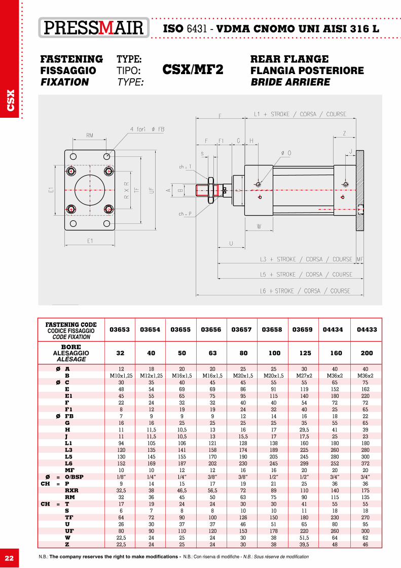
12M10x1,25
30484522871611119412013015210
1/8”9
32,532176642680
22,522,5
Ø A B Ø C E E1 F F1 Ø FB G H J L1 L3 L5 L6 MF Ø = O/BSP CH = P RXR RM CH = T S TF U UF W Z.
18M12x1,25
3554552412916
11,511,510513514516910
1/4”1438361977230902424
20M16x1,5
4069653219925
10,510,510614115518712
1/4”15
46,54524890371102525
20M16x1,5
4569753219925131312115817020212
3/8”17
56,550248
100371202424
25M20x1,5
4586954024122516
15,512817419023016
3/8”1972633010126461533030
25M20x1,5
559111540321425171713818920524516
1/2”2189753010150511783838
30M27x2
5511914054401635
29,517,516022524529920
1/2”251109041111806522051,539,5
40M36x2
6515218072251855412518026028025220
3/4”361401155518230802606448
40M36x2
7516222072652265392318028030037220
3/4”361751355518270953006246
BOREALESAGGIO
ALÉSAGE
FASTENING CODECODICE FISSAGGIO
CODE FIXATION
32 40 50 63 80 100 125 160 200
03653 03654 03655 03656 03657 03658 03659 04434 04433
FASTENING TYPE: REAR FLANGEFISSAGGIO TIPO: CSX/MF2 FLANGIA POSTERIOREFIXATION TYPE: BRIDE ARRIERE
CS
X
N.B.: The company reserves the right to make modifications - N.B.: Con riserva di modifiche - N.B.: Sous réserve de modification
ISO 6431 - VDMA CNOMO UNI AISI 316 L
23
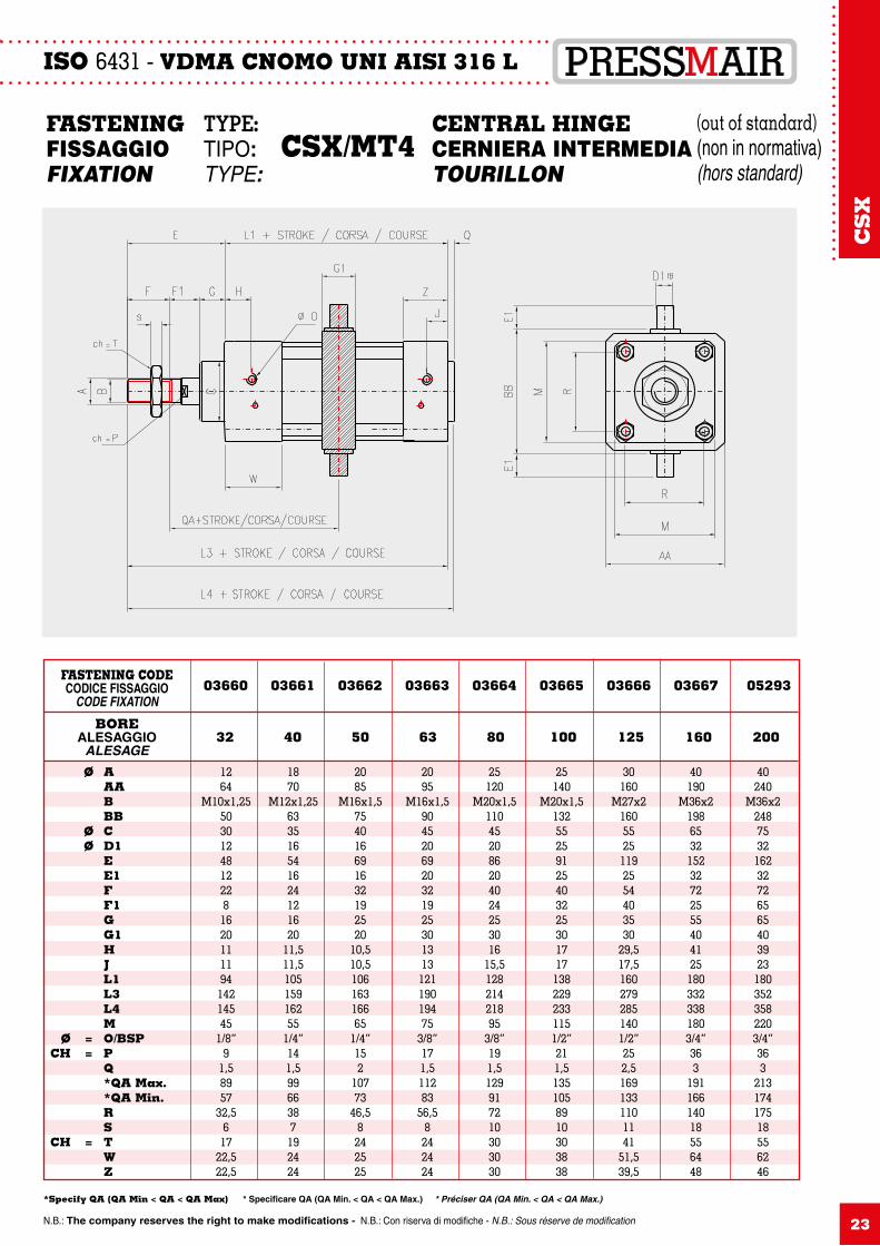
1264
M10x1,255030124812228162011119414214545
1/8”9
1,58957
32,5617
22,522,5
Ø A AA B BB Ø C Ø D1 E E1 F F1 G G1 H J L1 L3 L4 M Ø = O/BSP CH = P Q *QA Max. *QA Min. R S CH = T W Z
1870
M12x1,25633516541624121620
11,511,510515916255
1/4”141,59966387192424
2085
M16x1,5754016691632192520
10,510,510616316665
1/4”152
10773
46,58242525
2095
M16x1,5904520692032192530131312119019475
3/8”171,511283
56,58242424
25120
M20x1,5110452086204024253016
15,512821421895
3/8”191,5129917210303030
25140
M20x1,5132552591254032253017171382292331151/2”211,51351058910303838
30160
M27x216055251192554403530
29,517,51602792851401/2”252,51691331101141
51,539,5
40190
M36x21986532152327225554041251803323381803/4”363
19116614018556448
40240
M36x22487532162327265654039231803523582203/4”363
21317417518556246
BOREALESAGGIO
ALESAGE
FASTENING CODECODICE FISSAGGIO
CODE FIXATION
32 40 50 63 80 100 125 160 200
03660 03661 03662 03663 03664 03665 03666 03667 05293
FASTENING TYPE: CENTRAL HINGEFISSAGGIO TIPO: CSX/MT4 CERNIERA INTERMEDIAFIXATION TYPE: TOURILLON
(out of standard) (non in normativa)(hors standard)
*Specify QA (QA Min < QA < QA Max) * Specificare QA (QA Min. < QA < QA Max.) * Préciser QA (QA Min. < QA < QA Max.)
CS
X
ISO 6431 - VDMA CNOMO UNI AISI 316 L
N.B.: The company reserves the right to make modifications - N.B.: Con riserva di modifiche - N.B.: Sous réserve de modification24
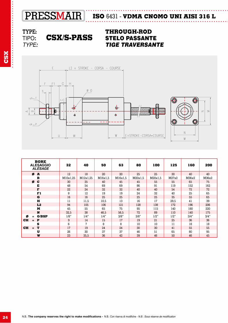
12M10x1,25
304822816119445
32,51/8”
96172623
Ø A B Ø C E F F1 G H L2 M N Ø = O/BSP CH = P S CH = T U W
18M12x1,25
3554241216
11,51055538
1/4”1471930
35,5
20M16x1,5
4069321925
10,510665
46,51/4”158243736
20M16x1,5
45693219251312175
56,53/8”178243742
25M20x1,5
4586402425161289572
3/8”1910304639
25M20x1,5
55914032251713811589
1/2”2110305146
30M27x2
55119544035
29,51721401101/2”2511416550
40M36x2
65152722555411961801403/4”3618558046
40M36x2
75162726565392062201753/4”3618559545
BOREALESAGGIO
ALÉSAGE32 40 50 63 80 100 125 160 200
TYPE: THROUGH-RODTIPO: CSX/S-PASS STELO PASSANTETYPE: TIGE TRAVERSANTE
CS
X
N.B.: The company reserves the right to make modifications - N.B.: Con riserva di modifiche - N.B.: Sous réserve de modification 25
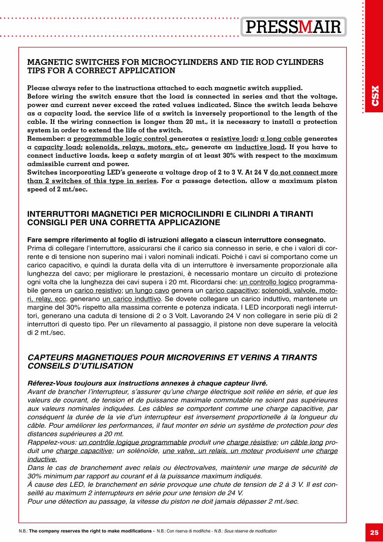
MAGNETIC SWITCHES FOR MICROCYLINDERS AND TIE ROD CYLINDERSTIPS FOR A CORRECT APPLICATION
Please always refer to the instructions attached to each magnetic switch supplied.Before wiring the switch ensure that the load is connected in series and that the voltage, power and current never exceed the rated values indicated. Since the switch leads behave as a capacity load, the service life of a switch is inversely proportional to the length of the cable. If the wiring connection is longer than 20 mt., it is necessary to install a protection system in order to extend the life of the switch.Remember: a programmable logic control generates a resistive load; a long cable generates a capacity load; solenoids, relays, motors, etc., generate an inductive load. If you have to connect inductive loads, keep a safety margin of at least 30% with respect to the maximum admissible current and power.Switches incorporating LED’s generate a voltage drop of 2 to 3 V. At 24 V do not connect more than 2 switches of this type in series. For a passage detection, allow a maximum piston speed of 2 mt./sec.
INTERRUTTORI MAGNETICI PER MICROCILINDRI E CILINDRI A TIRANTICONSIGLI PER UNA CORRETTA APPLICAZIONE
Fare sempre riferimento al foglio di istruzioni allegato a ciascun interruttore consegnato.Prima di collegare l’interruttore, assicurarsi che il carico sia connesso in serie, e che i valori di cor-rente e di tensione non superino mai i valori nominali indicati. Poiché i cavi si comportano come un carico capacitivo, e quindi la durata della vita di un interruttore è inversamente proporzionale alla lunghezza del cavo; per migliorare le prestazioni, è necessario montare un circuito di protezione ogni volta che la lunghezza dei cavi supera i 20 mt. Ricordarsi che: un controllo logico programma-bile genera un carico resistivo; un lungo cavo genera un carico capacitivo; solenoidi, valvole, moto-ri, relay, ecc. generano un carico induttivo. Se dovete collegare un carico induttivo, mantenete un margine del 30% rispetto alla massima corrente e potenza indicata. I LED incorporati negli interrut-tori, generano una caduta di tensione di 2 o 3 Volt. Lavorando 24 V non collegare in serie più di 2 interruttori di questo tipo. Per un rilevamento al passaggio, il pistone non deve superare la velocità di 2 mt./sec.
CAPTEURS MAGNETIQUES POUR MICROVERINS ET VERINS A TIRANTSCONSEILS D’UTILISATION
Réferez-Vous toujours aux instructions annexes à chaque capteur livré.Avant de brancher l’interrupteur, s’assurer qu’une charge électrique soit reliée en série, et que les valeurs de courant, de tension et de puissance maximale commutable ne soient pas supérieures aux valeurs nominales indiquées. Les câbles se comportent comme une charge capacitive, par conséquent la durée de la vie d’un interrupteur est inversement proportionelle à la longueur du câble. Pour améliorer les performances, il faut monter en série un système de protection pour des distances supérieures a 20 mt.Rappelez-vous: un contrôle logique programmable produit une charge résistive; un câble long pro-duit une charge capacitive; un solénoïde, une valve, un relais, un moteur produisent une charge inductive.Dans le cas de branchement avec relais ou électrovalves, maintenir une marge de sécurité de 30% minimum par rapport au courant et à la puissance maximum indiqués.À cause des LED, le branchement en série provoque une chute de tension de 2 à 3 V. Il est con-seillé au maximum 2 interrupteurs en série pour une tension de 24 V.Pour une détection au passage, la vitesse du piston ne doit jamais dépasser 2 mt./sec.
CS
X
ISO 6431 - VDMA CNOMO UNI AISI 316 L
N.B.: The company reserves the right to make modifications - N.B.: Con riserva di modifiche - N.B.: Sous réserve de modification26
BOREALESAGGIO
ALÉSAGE
FROMDALDU
Ø 32÷200
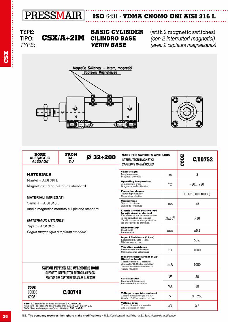
MATERIALS
Mantel = AISI 316 L
Magnetic ring on piston as standard
MATERIALI IMPIEGATI
Camicia = AISI 316 L
Anello magnetico montato sul pistone standard
MATERIAUX UTILISES
Tuyau = AISI 316 LBague magnétique sur piston standard
Note: All kinds can be used both with C.C. and C.A.Nota: Tutti i tipi possono essere adoperati sia con C.C. sia con C.A.Note: Tous les types peuvent être utilisés en C.C. ou C.A.
CODECODICECODE
C/00748
SWITCH FITTING ALL CYLINDER’S BORESUPPORTO INTERRUTTORI TUTTI GLI ALESAGGIFIXATION DES CAPTEURS TOUS LES ALÉSAGES
MAGNETIC SWITCHES WITH LEDSINTERRUTTORI MAGNETICICAPTEURS MAGNÉTIQUES
C/00752
Cable lengthLunghezza cavoLongueur du câble
Operating temperatureTemperatura d’usoTempérature d’utilisation
Protection degreeGrado di protezioneDegré de protection
Closing timeTempo di chiusuraTemps de fermeture
Electric life with resistive load(or with circuit protection)Vita elettrica con carico resistivo(o con circuiti di protezione)Vie eléctrique avec charge résistive(ou avec circuit de protection)
RepeatabilityRipetitivitàRépétabilité
Impact Resistence (11 ms)Resistenza all’urto (11 ms)Résistance au choc
Vibration resistanceResistenza alle vibrazioniRésistance aux vibrations
Max switching current at 25°(Resistive load)Corrente max. di Commuta-zione a 25° C (Carico resistivo)Courant max de commutation 25°(charge résistive)
Cut-off powerPotenza d’interruzionePuissance d’interruption
Voltage range (dc. and a.c.)Campo di tensione (cc. e c.a.)Tension d’utilisation (c.c. et c.a.)
Voltage dropCaduta di tensione massimaChute de tension max
m
°C
ms
Nx106
mm
Hz
mA
W
VA
V
∆V
3
-30... +80
IP 67 (DIN 40050)
≤2
>10
±0,1
50 g
1000
1000
50
50
3... 250
2,5
TYPE: BASIC CYLINDER (with 2 magnetic switches)TIPO: CSX/A+2IM CILINDRO BASE (con 2 interruttori magnetici)TYPE: VÉRIN BASE (avec 2 capteurs magnétiques)
COD
E
CS
X
N.B.: The company reserves the right to make modifications - N.B.: Con riserva di modifiche - N.B.: Sous réserve de modification
ISO 6431 - VDMA CNOMO UNI AISI 316 L
27
ACCESSORIES FORKSACCESSORI FORCELLEACCESSOIRES CHAPE DE TIGE
2010204310281018151457
10,540526,520
12,9M10x1,25
1519
M10x1,251713°20
A B BC CE CN D Ø = DD Ø = DF E EN G H L1 L2 L NN O S J K KK ch=K ∂ T
22122450123212201816661248626,524
15,4M12x1,25
17,522
M12x1,251913°24
2816326416421626242185156483832
19,3M16x1,5
2227
M16x1,52415°32
2816326416421626242185156483832
19,3M16x1,5
2227
M16x1,52415°32
3320407720502034302510218801051040
24,3M20x1,5
27,534
M20x1,53015°40
3320407720502034302510218801051040
24,3M20x1,5
27,534
M20x1,53015°40
513058110307020523437145251151481554
34,8M27x2
4050
M27x24115°58
563570125358035604043165281441741772
37,7M36x2
4658
M36x25015°70
563570125358035604043165281441741772
37,7M36x2
4658
M36x25015°70
BOREALESAGGIO
ALESAGE
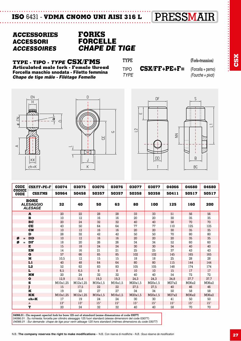
CSX/FF+PE+F
CSX/FMS
32 40 50 63 80 100 125 160 200
03074
50964
03075
50458
03076
50357
03076
50357
03077
50358
03077
50358
04066
50411
04680
50517
04680
50517
CODECODICECODE
TYPE - TIPO - TYPE CSX/FMSArticulated male fork - Female threadForcella maschio snodata - Filetto femminaChape de tige mâle - Filétage Femelle
TYPE (Fork+trunnion)
TIPO CSX/FF+PE+F= (Forcella + perno)TYPE (Fourche + pivot)
CS
X
04066.01 : On request: special fork for bore 125 out of standard (same dimensions of code 03077)04066.01 : Su richiesta: forcella per cilindro alesaggio 125 fuori standard (stesse dimensioni del code 03077)04066.01 : Sur demande: chape de tige pour verin alésage 125 hors standard (mêmes dimensions du code 03077)
ISO 6431 - VDMA CNOMO UNI AISI 316 L
N.B.: The company reserves the right to make modifications - N.B.: Con riserva di modifiche - N.B.: Sous réserve de modification28
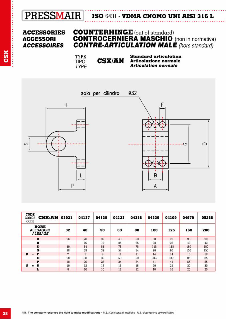
ACCESSORIES COUNTERHINGE (out of standard)ACCESSORI CONTROCERNIERA MASCHIO (non in normativa)ACCESSOIRES CONTRE-ARTICULATION MALE (hors standard)
TYPETIPO CSX/ANTYPE
Standard articulationArticolazione normaleArticulation normale
26
402872818108
A B D G Ø = F H P Ø = S L
28165438938261210
32165438938261210
402575541150341612
502575541150341612
60321159014
63,5412016
70321159014
63,5412516
90431801501885553020
90431801501885553020
BOREALESAGGIO
ALESAGE32 40 50 63 80 100 125 160 200
CODECODICECODE
03921 04137 04138 04123 04338 04339 04109 04679 05288CSX/AN
CS
X
N.B.: The company reserves the right to make modifications - N.B.: Con riserva di modifiche - N.B.: Sous réserve de modification
ISO 6431 - VDMA CNOMO UNI AISI 316 L
29
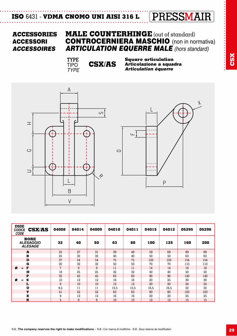
2525372071832108
8,54195
A B D G Ø = F H P Ø = S L U V X R
273254329254512101152129
313254329254512101152129
394075501132631612
12,5631610
494075501132631612
12,5631610
5950103701440902020
16,5802012
6950103701440902520
16,5802012
896315411018501403024221032515
896315411018501403024221032515
BOREALESAGGIO
ALESAGE32 40 50 63 80 100 125 160 200
04008 04014 04009 04010 04011 04015 04012 05295 05296CODE
CODICECODE
CSX/AS
ACCESSORIES MALE COUNTERHINGE (out of standard)ACCESSORI CONTROCERNIERA MASCHIO (non in normativa)ACCESSOIRES ARTICULATION EQUERRE MALE (hors standard)
TYPETIPO CSX/ASTYPE
Square articulationArticolazione a squadraArticulation équerre
CS
X
ISO 6431 - VDMA CNOMO UNI AISI 316 L
N.B.: The company reserves the right to make modifications - N.B.: Con riserva di modifiche - N.B.: Sous réserve de modification30
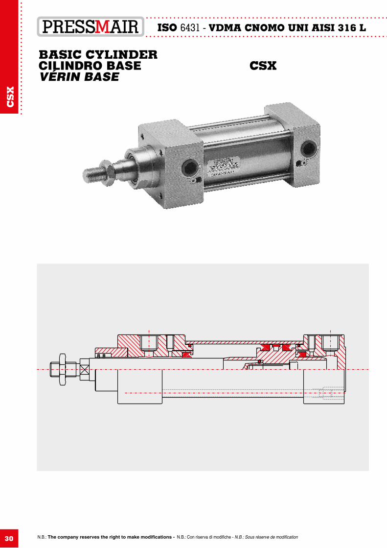
BASIC CYLINDERCILINDRO BASE CSXVÉRIN BASE
CS
X
AISI 316 LCVX
31
CV
X
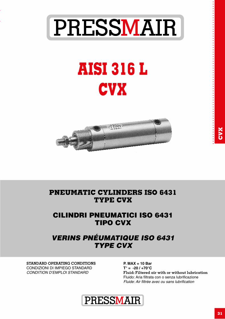
PNEUMATIC CYLINDERS ISO 6431TYPE CVX
CILINDRI PNEUMATICI ISO 6431TIPO CVX
VERINS PNÉUMATIQUE ISO 6431TYPE CVX
STANDARD OPERATING CONDITIONSCONDIZIONI DI IMPIEGO STANDARDCONDITION D’EMPLOI STANDARD
P. MAX = 10 BarT° = -20 / +70°CFluid: Filtered air with or without lubricationFluido: Aria filtrata con o senza lubrificazioneFluide: Air filtrée avec ou sans lubrification
ISO DP 6431 AISI 316 L
N.B.: The company reserves the right to make modifications - N.B.: Con riserva di modifiche - N.B.: Sous réserve de modification32
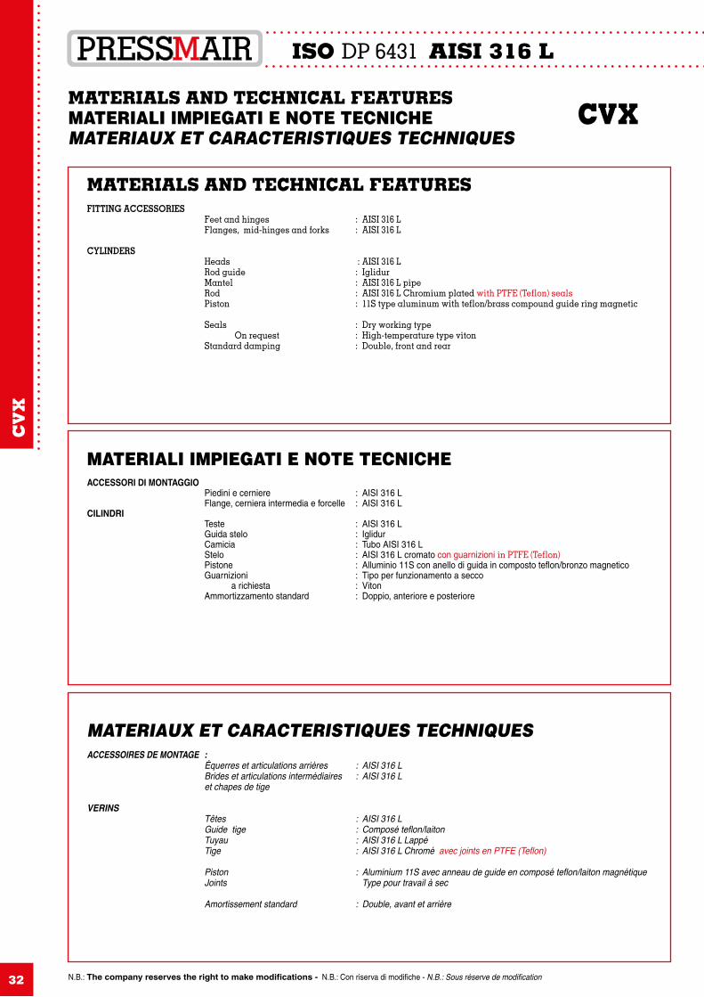
MATERIALS AND TECHNICAL FEATURESMATERIALI IMPIEGATI E NOTE TECNICHE CVXMATERIAUX ET CARACTERISTIQUES TECHNIQUES
MATERIALS AND TECHNICAL FEATURESFITTING ACCESSORIES Feet and hinges : AISI 316 L Flanges, mid-hinges and forks : AISI 316 L
CYLINDERS Heads : AISI 316 L Rod guide : Iglidur Mantel : AISI 316 L pipe Rod : AISI 316 L Chromium plated with PTFE (Teflon) seals Piston : 11S type aluminum with teflon/brass compound guide ring magnetic Seals : Dry working type On request : High-temperature type viton Standard damping : Double, front and rear
MATERIALI IMPIEGATI E NOTE TECNICHEACCESSORI DI MONTAGGIO Piedini e cerniere : AISI 316 L Flange, cerniera intermedia e forcelle : AISI 316 LCILINDRI Teste : AISI 316 L Guida stelo : Iglidur Camicia : Tubo AISI 316 L Stelo : AISI 316 L cromato con guarnizioni in PTFE (Teflon) Pistone : Alluminio 11S con anello di guida in composto teflon/bronzo magnetico Guarnizioni : Tipo per funzionamento a secco a richiesta : Viton Ammortizzamento standard : Doppio, anteriore e posteriore
MATERIAUX ET CARACTERISTIQUES TECHNIQUESACCESSOIRES DE MONTAGE : Équerres et articulations arrières : AISI 316 L Brides et articulations intermédiaires : AISI 316 L et chapes de tige
VERINS Têtes : AISI 316 L Guide tige : Composé teflon/laiton Tuyau : AISI 316 L Lappé Tige : AISI 316 L Chromé avec joints en PTFE (Teflon) Piston : Aluminium 11S avec anneau de guide en composé teflon/laiton magnétique Joints Type pour travail à sec Amortissement standard : Double, avant et arrière
CV
X
N.B.: The company reserves the right to make modifications - N.B.: Con riserva di modifiche - N.B.: Sous réserve de modification
ISO DP 6431 AISI 316 L
33
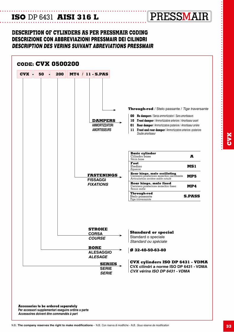
DESCRIPTION OF CYLINDERS AS PER PRESSMAIR CODING DESCRIZIONE CON ABBREVIAZIONI PRESSMAIR DEI CILINDRI DESCRIPTION DES VERINS SUIVANT ABREVIATIONS PRESSMAIR
CODE: CVX 0500200
CVX 50 - 200- MT4 / 11 - S.PAS
Accessories to be ordered separatelyPer accessori supplementari eseguire ordine a parteAccessoires doivent être commandés à part
SERIESSERIESERIE
CVX cylinders ISO DP 6431 - VDMACVX cilindri a norme ISO DP 6431 - VDMACVX vérins ISO DP 6431 - VDMA
BOREALESAGGIOALESAGE
Ø 32-40-50-63-80
STROKECORSACOURSE
FASTENINGSFISSAGGIFIXATIONS
DAMPERSAMMORTIZZATORIAMORTISSEURS
Standard or specialStandard o specialeStandard ou spéciale
Basic cylinderCilindro baseVérin base
FootPiedinoÉquerre
Rear hinge, male oscillatingCerniera posteriore maschio oscillanteArticulation arrière mâle rotulé
Rear hinge, male fixedCerniera posteriore maschio fissaTenon mâle
Through-rodStelo passanteTige traversante
A
MS1
MP5
MP4
S.PASS
00100111
Through-rod / Stelo passante / Tige traversante
No dampers / Senza ammortizzatori / Sans amortisseursFront damper / Ammortizzatore anteriore / Amortisseur avantRear damper / Ammortizzatore posteriore / Amortisseur arrièreFront and rear damper / Ammortizzatore anteriore -posterioreDouble amortisseur
CV
X
ISO DP 6431 AISI 316 L
N.B.: The company reserves the right to make modifications - N.B.: Con riserva di modifiche - N.B.: Sous réserve de modification34
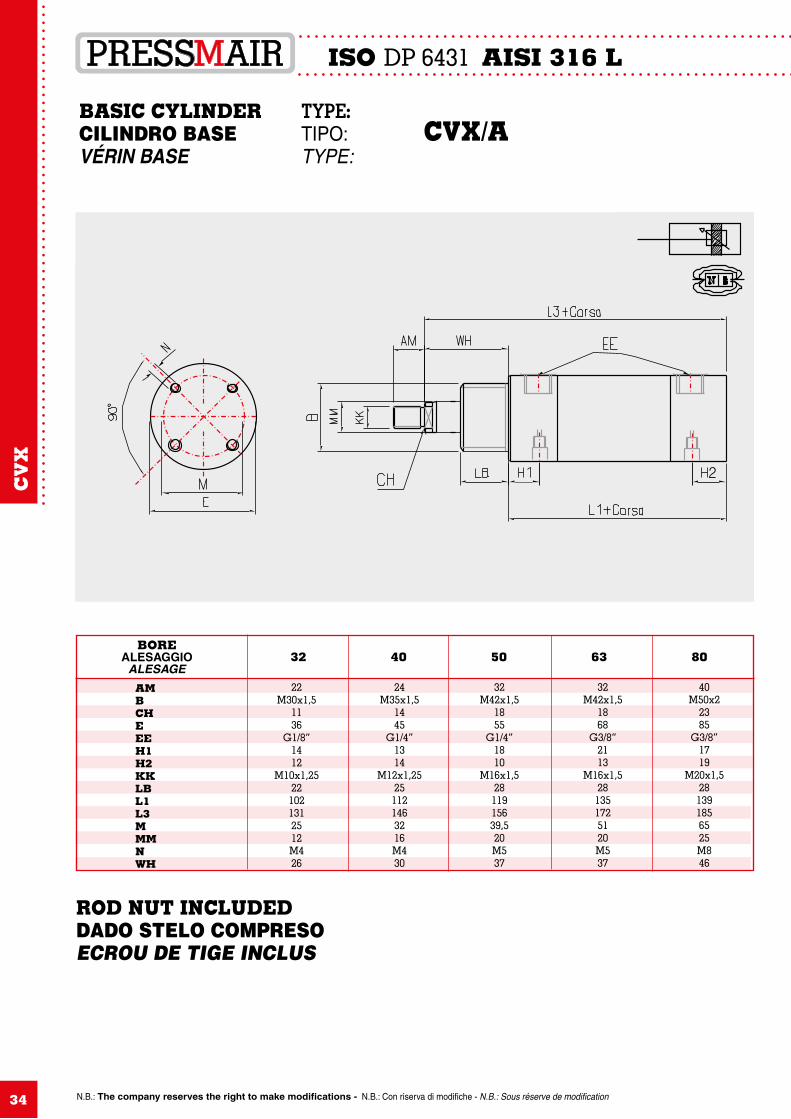
22M30x1,5
1136
G1/8”1412
M10x1,25221021312512M426
AM B CH E EE H1 H2 KK LB L1 L3 M MM N WH
24M35x1,5
1445
G1/4”1314
M12x1,25251121463216M430
32M42x1,5
1855
G1/4”1810
M16x1,52811915639,520M537
32M42x1,5
1868
G3/8”2113
M16x1,5281351725120M537
40M50x2
2385
G3/8”1719
M20x1,5281391856525M846
BOREALESAGGIO
ALESAGE32 40 50 63 80
BASIC CYLINDER TYPE: CILINDRO BASE TIPO: CVX/A VÉRIN BASE TYPE:
CV
X
ROD NUT INCLUDEDDADO STELO COMPRESOECROU DE TIGE INCLUS
N.B.: The company reserves the right to make modifications - N.B.: Con riserva di modifiche - N.B.: Sous réserve de modification
ISO DP 6431 AISI 316 L
35
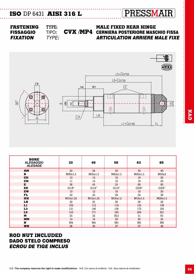
22M30x1,5
101136
G1/8”1022
M10x1,2522
1021311532512M426
AM B CD CH E EE EW FL KK LB L1 L3 L5 M MM N WH
24M35x1,5
121445
G1/4”1225
M12x1,2525
1121461713216M430
32M42x1,5
161855
G1/4”1629
M16x1,528
11915618539,520M537
32M42x1,5
161868
G3/8”1632
M16x1,528
1351722045120M537
40M50x2
202385
G3/8”2036
M20x1,528
1391852216525M846
BOREALESAGGIO
ALESAGE32 40 50 63 80
FASTENING TYPE: MALE FIXED REAR HINGEFISSAGGIO TIPO: CVX /MP4 CERNIERA POSTERIORE MASCHIO FISSAFIXATION TYPE: ARTICULATION ARRIERE MALE FIXE
CV
X
ROD NUT INCLUDEDDADO STELO COMPRESOECROU DE TIGE INCLUS
ISO DP 6431 AISI 316 L
N.B.: The company reserves the right to make modifications - N.B.: Con riserva di modifiche - N.B.: Sous réserve de modification36
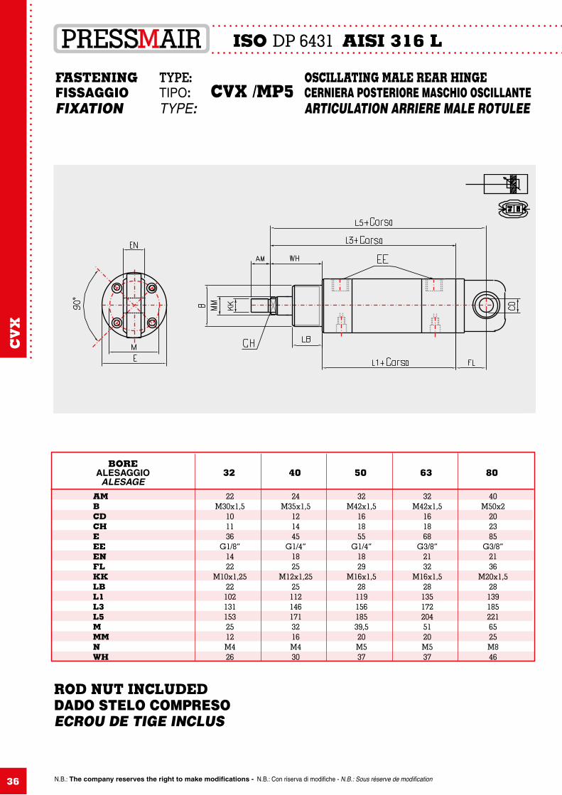
FASTENING TYPE: OSCILLATING MALE REAR HINGEFISSAGGIO TIPO: CVX /MP5 CERNIERA POSTERIORE MASCHIO OSCILLANTEFIXATION TYPE: ARTICULATION ARRIERE MALE ROTULEE
22M30x1,5
101136
G1/8”1422
M10x1,2522
1021311532512M426
AM B CD CH E EE EN FL KK LB L1 L3 L5 M MM N WH
24M35x1,5
121445
G1/4”1825
M12x1,2525
1121461713216M430
32M42x1,5
161855
G1/4”1829
M16x1,528
11915618539,520M537
32M42x1,5
161868
G3/8”2132
M16x1,528
1351722045120M537
40M50x2
202385
G3/8”2136
M20x1,5281391852216525M846
BOREALESAGGIO
ALESAGE32 40 50 63 80
CV
X
ROD NUT INCLUDEDDADO STELO COMPRESOECROU DE TIGE INCLUS
37
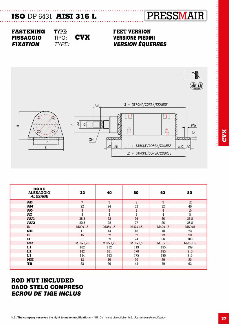
FASTENING TYPE: FEET VERSIONFISSAGGIO TIPO: CVX VERSIONE PIEDINIFIXATION TYPE: VERSION ÈQUERRES
72293
28,520,5
M30x1,5114551
M10x1,251021421441232
AB AM AO AT AU1 AU2 B CH E H KK L1 L2 L3 MM TR
92493
3222
M35x1,5145259
M12x1,251121611631636
93294
3627
M42x1,5186274
M16x1,51191701752045
93294
3626
M42x1,5187286
M16x1,51351851902050
1240155
38,535,5
M50x22390
108M20x1,5
1392102152563
BOREALESAGGIO
ALESAGE32 40 50 63 80
N.B.: The company reserves the right to make modifications - N.B.: Con riserva di modifiche - N.B.: Sous réserve de modification
ISO DP 6431 AISI 316 L
CV
X
ROD NUT INCLUDEDDADO STELO COMPRESOECROU DE TIGE INCLUS
N.B.: The company reserves the right to make modifications - N.B.: Con riserva di modifiche - N.B.: Sous réserve de modification38
ISO DP 6431 AISI 316 L
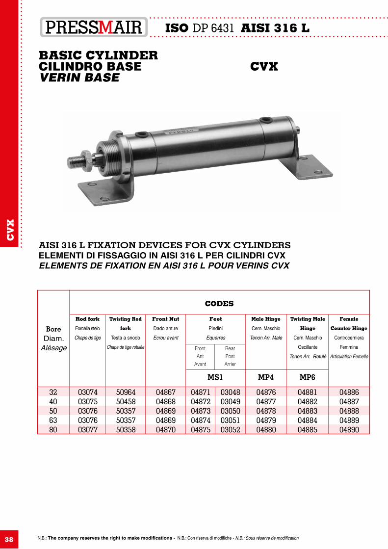
AISI 316 L FIXATION DEVICES FOR CVX CYLINDERSELEMENTI DI FISSAGGIO IN AISI 316 L PER CILINDRI CVXELEMENTS DE FIXATION EN AISI 316 L POUR VERINS CVX
CODES
CV
X
BASIC CYLINDERCILINDRO BASE CVXVERIN BASE
BoreDiam.
Alésage
Rod fork
Forcella stelo
Chape de tige
Twisting Rod
fork
Testa a snodo
Chape de tige rotulée
Front Nut
Dado ant.re
Ecrou avant
Feet
Piedini
Equerres
Male Hinge
Cern. Maschio
Tenon Arr. Male
Twisting Male
Hinge
Cern. Maschio
Oscillante
Tenon Arr. Rotulé
Female
Counter Hinge
Controcerniera
Femmina
Articulation Femelle
MS1 MP4 MP6
3240506380
0307403075030760307603077
5096450458503575035750358
0486704868048690486904870
0487104872048730487404875
0304803049030500305103052
0487604877048780487904880
0488104882048830488404885
0488604887048880488904890
FrontAnt
Avant
RearPostArrier
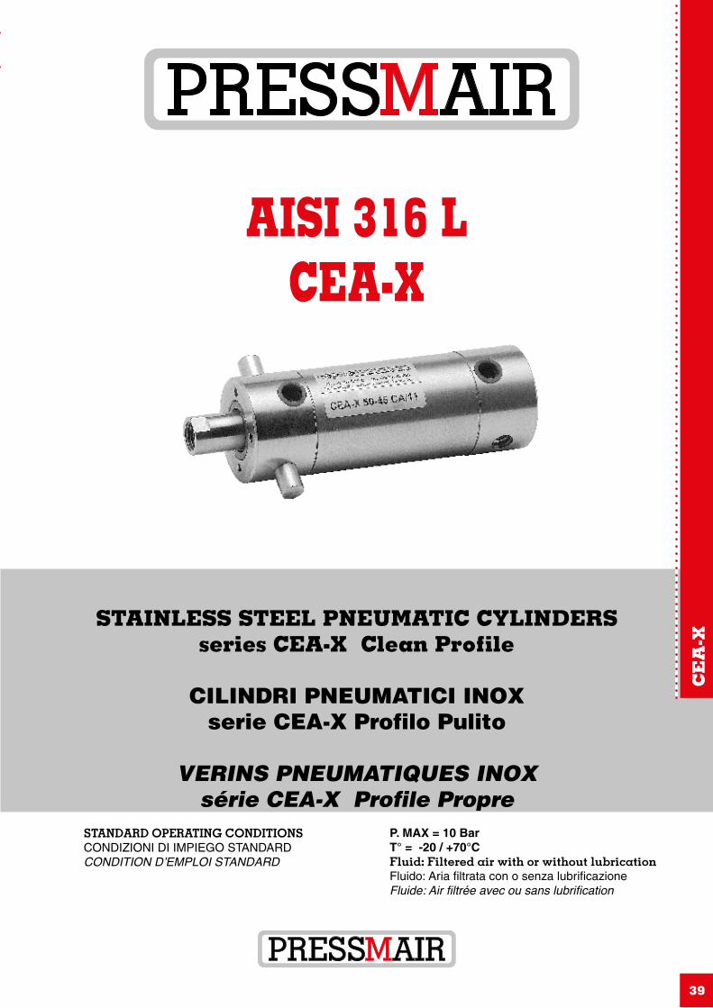
AISI 316 LCEA-X
39
STANDARD OPERATING CONDITIONSCONDIZIONI DI IMPIEGO STANDARDCONDITION D’EMPLOI STANDARD
STAINLESS STEEL PNEUMATIC CYLINDERSseries CEA-X Clean Profile
CILINDRI PNEUMATICI INOXserie CEA-X Profilo Pulito
VERINS PNEUMATIQUES INOXsérie CEA-X Profile Propre
P. MAX = 10 BarT° = -20 / +70°CFluid: Filtered air with or without lubricationFluido: Aria filtrata con o senza lubrificazioneFluide: Air filtrée avec ou sans lubrification
CE
A-X
N.B.: The company reserves the right to make modifications - N.B.: Con riserva di modifiche - N.B.: Sous réserve de modification
CLEAN PROFILE CYLINDERS AISI 316 L
40
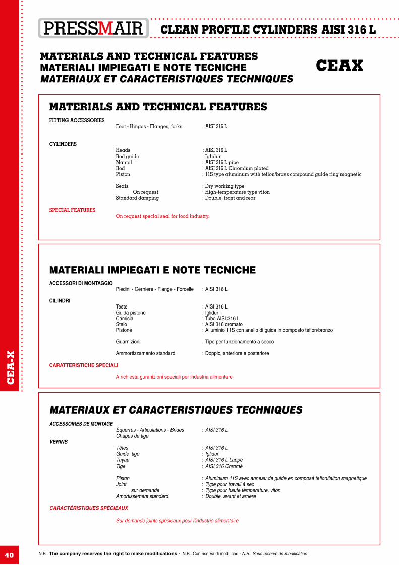
MATERIALS AND TECHNICAL FEATURESMATERIALI IMPIEGATI E NOTE TECNICHE CEAXMATERIAUX ET CARACTERISTIQUES TECHNIQUES
MATERIALS AND TECHNICAL FEATURESFITTING ACCESSORIES Feet - Hinges - Flanges, forks : AISI 316 L
CYLINDERS Heads : AISI 316 L Rod guide : Iglidur Mantel : AISI 316 L pipe Rod : AISI 316 L Chromium plated Piston : 11S type aluminum with teflon/brass compound guide ring magnetic Seals : Dry working type On request : High-temperature type viton Standard damping : Double, front and rear
SPECIAL FEATURES On request special seal for food industry.
MATERIALI IMPIEGATI E NOTE TECNICHEACCESSORI DI MONTAGGIO Piedini - Cerniere - Flange - Forcelle : AISI 316 L CILINDRI Teste : AISI 316 L Guida pistone : Iglidur Camicia : Tubo AISI 316 L Stelo : AISI 316 cromato Pistone : Alluminio 11S con anello di guida in composto teflon/bronzo
Guarnizioni : Tipo per funzionamento a secco
Ammortizzamento standard : Doppio, anteriore e posteriore CARATTERISTICHE SPECIALI A richiesta guranizioni speciali per industria alimentare
MATERIAUX ET CARACTERISTIQUES TECHNIQUESACCESSOIRES DE MONTAGE Équerres - Articulations - Brides : AISI 316 L Chapes de tigeVERINS Têtes : AISI 316 L Guide tige : Iglidur Tuyau : AISI 316 L Lappé Tige : AISI 316 Chromé
Piston : Aluminium 11S avec anneau de guide en composé teflon/laiton magnetique Joint : Type pour travail à sec sur demande : Type pour haute témperature, viton Amortissement standard : Double, avant et arrière
CARACTÉRISTIQUES SPÉCIEAUX
Sur demande joints spécieaux pour l’industrie alimentaire
CE
A-X
N.B.: The company reserves the right to make modifications - N.B.: Con riserva di modifiche - N.B.: Sous réserve de modification
CEAX AISI 316 L
41
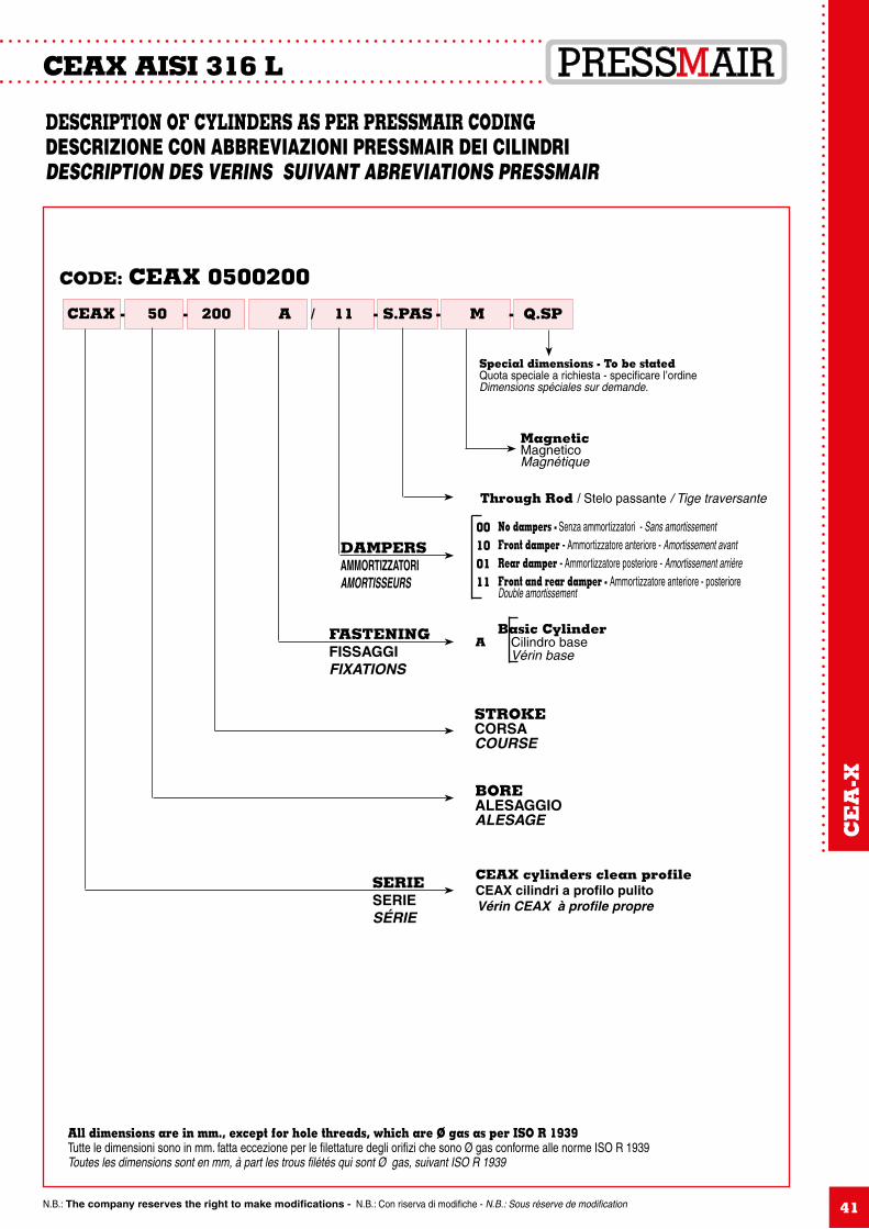
DESCRIPTION OF CYLINDERS AS PER PRESSMAIR CODING DESCRIZIONE CON ABBREVIAZIONI PRESSMAIR DEI CILINDRI DESCRIPTION DES VERINS SUIVANT ABREVIATIONS PRESSMAIR
CEAX 50 - 200- A / 11 - S.PAS - M - Q.SP
All dimensions are in mm., except for hole threads, which are Ø gas as per ISO R 1939Tutte le dimensioni sono in mm. fatta eccezione per le filettature degli orifizi che sono Ø gas conforme alle norme ISO R 1939Toutes les dimensions sont en mm, à part les trous filétés qui sont Ø gas, suivant ISO R 1939
SERIESERIESÉRIE
CEAX cylinders clean profileCEAX cilindri a profilo pulitoVérin CEAX à profile propre
STROKECORSACOURSE
FASTENINGFISSAGGIFIXATIONS
DAMPERSAMMORTIZZATORIAMORTISSEURS
No dampers - Senza ammortizzatori - Sans amortissementFront damper - Ammortizzatore anteriore - Amortissement avantRear damper - Ammortizzatore posteriore - Amortissement arrièreFront and rear damper - Ammortizzatore anteriore - posteriore Double amortissement
00100111
Through Rod / Stelo passante / Tige traversante
MagneticMagneticoMagnétique
Special dimensions - To be stated Quota speciale a richiesta - specificare l’ordine Dimensions spéciales sur demande.
Basic CylinderCilindro baseVérin base
A
BOREALESAGGIOALESAGE
CODE: CEAX 0500200
CE
A-X
N.B.: The company reserves the right to make modifications - N.B.: Con riserva di modifiche - N.B.: Sous réserve de modification
CEAX AISI 316 L
42
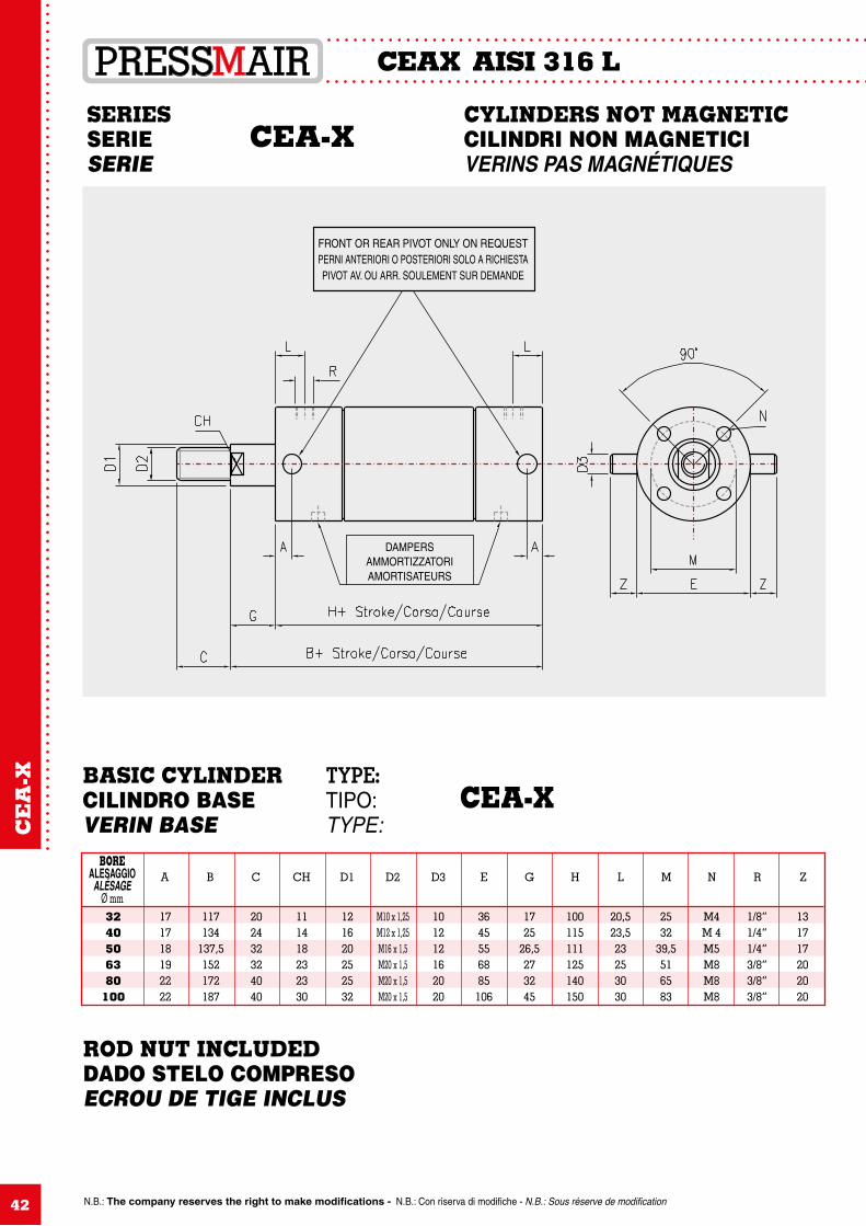
SERIES CYLINDERS NOT MAGNETICSERIE CEA-X CILINDRI NON MAGNETICISERIE VERINS PAS MAGNÉTIQUES
3240506380
100
BOREALESAGGIO
ALÉSAGEØ mm
171718192222
117134
137,5152172187
202432324040
111418232330
121620252532
M10 x 1,25M12 x 1,25M16 x 1,5M20 x 1,5M20 x 1,5M20 x 1,5
101212162020
3645556885106
1725
26,5273245
100115111125140150
20,523,523253030
2532
39,5516583
M4M 4M5M8M8M8
1/8”1/4”1/4”3/8”3/8”3/8”
131717202020
A B C CH D1 D2 D3 E G H L M N R Z
BASIC CYLINDER TYPE: CILINDRO BASE TIPO: CEA-XVERIN BASE TYPE:
FRONT OR REAR PIVOT ONLY ON REQUESTPERNI ANTERIORI O POSTERIORI SOLO A RICHIESTAPIVOT AV. OU ARR. SOULEMENT SUR DEMANDE
DAMPERSAMMORTIZZATORIAMORTISATEURS
CE
A-X
ROD NUT INCLUDEDDADO STELO COMPRESOECROU DE TIGE INCLUS
N.B.: The company reserves the right to make modifications - N.B.: Con riserva di modifiche - N.B.: Sous réserve de modification
CEAX AISI 316 L
43
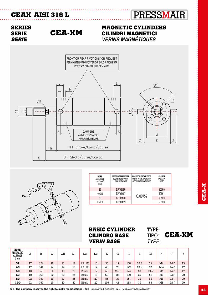
3240506380
100
BOREALESAGGIO
ALÉSAGEØ mm
171718192222
124141150166183192
202432324040
111418232330
121620252532
M10 x 1,25M12 x 1,25M16 x 1,5M20 x 1,5M20 x 1,5M20 x 1,5
101212162020
3645556885106
1725
26,5273245
106122124139151155
20,523,523253030
2532
39,5516583
M4M 4M5M8M8M8
1/8”1/4”1/4”3/8”3/8”3/8”
131717202020
A B C CH D1 D2 D3 E G H L M N R Z
BASIC CYLINDER TYPE: CILINDRO BASE TIPO: CEA-XMVERIN BASE TYPE:
SERIES MAGNETIC CYLINDERS SERIE CEA-XM CILINDRI MAGNETICISERIE VERINS MAGNÉTIQUES
FRONT OR REAR PIVOT ONLY ON REQUESTPERNI ANTERIORI O POSTERIORI SOLO A RICHIESTA
PIVOT AV. OU ARR. SUR DEMANDE
DAMPERSAMMORTIZZATORIAMORTISATEURS
CE
A-X
BOREALESAGGIO
ALÉSAGEØ mm
FITTING DEVICE CODECODICE DEL SUPPORTO
CODE DU SUPPORT
MAGNETIC SWITCH CODECODICE INTERR. MAGNETICOCODE DU CAPTEUR MAGNETIQUE
CLAMPSFASCETTA
BANDE
3240-50
6380-100
LP/02496LP/02497LP/02498LP/02499
50560505615056250563
C/00752
44
CEAX AISI 316 L
3240506380
100
030480304903050030510305203053
030540305503056030570305803059
BOREALESAGGIO
ALESAGEA B C D E F G H I L N P Q R S T
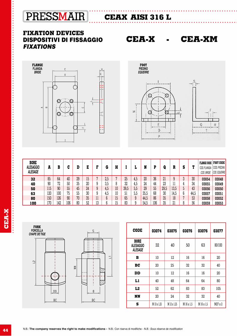
FIXATION DEVICES DISPOSITIVI DI FISSAGGIO CEA-X - CEA-XM FIXATIONS
FLANGE CODECOD. FLANGIACOD. BRIDE
FOOT CODECOD. PIEDINICOD. EQUERRE
CODE 03074 03075 03076 03076 03077
BOREALESAGGIO
ALESAGE32 40 50 63 80/100
FORKFORCELLA
CHAPE DE TIGE
10
20
10
40
52
20
M 10 x 1,25
12
25
12
48
62
24
M 12 x 1,25
16
32
16
64
83
32
M 16 x 1,5
16
32
16
64
83
32
M 16 x 1,5
20
40
20
80
105
40
M27 x 2
B
BC
DD
L1
L2
NN
S
FLANGEFLANGIA
BRIDE
FOOTPIEDINO
EQUERRE
8590
115120150170
647290100126142
4050557590106
293545557080
152024303552
79991113
2,53,54,54,566
78
10101515
2532
39,5516583
4,54,55,55,599
202429
35,544,554,5
3644556886
106
2123
29,5303535
911
13,514,51821
345678
303443
44,55356
N.B.: The company reserves the right to make modifications - N.B.: Con riserva di modifiche - N.B.: Sous réserve de modification
CE
A-X
COMPACT PNEUMATIC CYLINDERSCBXT UNITOP SERIE
CILINDRI PNEUMATICI COMPATTISERIE CBXT UNITOP
VERINS PNEUMATIQUES COMPACTSSERIE CBXT UNITOP
AISI 316 LCBX-T
45
STANDARD OPERATING CONDITIONSCONDIZIONI DI IMPIEGO STANDARDCONDITION D’EMPLOI STANDARD
P. MAX = 10 BarT° = -20 / +70°CFluid: Filtered air with or without lubricationFluido: Aria filtrata con o senza lubrificazioneFluide: Air filtrée avec ou sans lubrification
CB
X-T
N.B.: The company reserves the right to make modifications - N.B.: Con riserva di modifiche - N.B.: Sous réserve de modification
CBX-T UNITOP AISI 316 L
46
AISI 316 L COMPACT CYLINDERS UNITOP AND GUIDE UNITS SERIES
The increasing market of AISI 316 L cylinders compels PRESSMAIR Srl to introduce two new lines of cyl-inders, compact type.1- AISI 316 L COMPACT CYLINDERS UNITOP TYPE ( basic code CBXT), bore from 12 mm to 100 mm,
stroke from 5 mm to 100 mm. As basic version they are magnetic, and on request they can be double or single acting; both versions can be equipped with anti-rotation device. UNITOP Compact cylinders can be used in every application where the environmental conditions do not allow the use of Aluminum Compact Cylinder; being realized following UNITOP specifications, they are totally interchangeable with the standard type currently sold in the market.
2- COMPACT GUIDE LINE UNITS. Bore is from 12 mm to 63 mm, stroke is from 10 mm to 100 mm; they are magnetic, and are double acting type only. Sliding guides are acid resistant material, cushioning is elastic.These units can be used when the cylinder is subject to strong external force and torque, and the environmental conditions do not allow the use of Aluminum Compact guide line. They are interchangeable with the most popular units sold in the market.
CILINDRI CORSA BREVE IN AISI 316 L SERIE UNITOP E UNITA’ DI GUIDA COMPATTE
Il mercato dei cilindri in acciaio inossidabile continuamente in espansione ha spinto la PRESSMAIR S.r.l. ad introdurre due nuove linee di prodotti, della serie “Cilindri a corsa breve”1- CILINDRI A CORSA BREVE IN AISI 316 L NORMA UNITOP (Codice base CBXT): alesaggio da 12 mm a
100 mm, corsa da 5 a 100 mm. In versione base essi sono magnetici, e possono essere forniti sia a doppio che e semplice effetto.
I cilindri UNITOP devono essere usati in tutte quelle applicazioni in cui le condizioni ambientali non consentono l’uso di prodotti in alluminio; essendo realizzati secondo le norme UNITOP, questi cilindri sono
totalmente intercambiabili con i tipi standard attualmente in vendita sul mercato.2- UNITA’ DI GUIDA COMPATTE. Alesaggio da 12 a 63 mm, corsa da 10 mm a 100 mm.; sono magnetici e a
doppio effetto solamente; le boccole di guida sono in materiale antiacido, e l’ammortizzo è di tipo elastico. Queste unità possono essere usate quando i componenti sono soggetti a robuste forze o momenti torcenti
esterni, e contemporaneamente le condizioni ambientali non consentono l’utilizzo di cilindri compatti in allu-minio. Sono totalmente intercambiabili con le unità di questo tipo più diffuse sul mercato.
VERINS COMPACTS EN AISI 316 L SERIE UNITOP ET UNITEES DE GUIDAGE COMPACTES
La diffusion des produits pnéumatique réalisés avec l’AISI 316 L a convaincu PRESSMAIR S.r.l. à réaliser deux nouvelles lignes de actuateurs, du type « COMPACTS » :1- VERINS COMPACTS EN AISI 316 L NORME UNITOP ( Code base CBXT) : alésage de 12 mm à 100 mm,
course de 5 mm à 100 mm. Dans la version base ils sont magnetiques, et peuvent être réalisés soit à double effet soit à simple effet. Ces vérins du typeUNITOP doivent être utilisés dans toutes les applications dans lequelles les conditions du
milieu ne permettent pas l’utilisation des vérins en aluminum ; puisqu’ils sont réalisés suivant les normes UNITOP, ils sont totalement interchangeables avec les types standards sur le marché.
2- UNITEES DE GUIDAGE COMPACTES. Alésage de 12 mm à 63 mm, course de 10 mm à 100 mm ; ils sont magnétiques et double effet seulement ; les guidages sont en materiel résistant à l’acide, et l’amortisement est du type élastique.
Ces unitées peuvent être utilisées quand les vérins sont soumis à des forces ou à des moments tordrant importants, et en même temp les conditions du milieu ne permettent pas de utiliser les vérins compacts en aluminum. Ils sont totalement interchangeables avec les types standards sur le marché.
CB
X-T
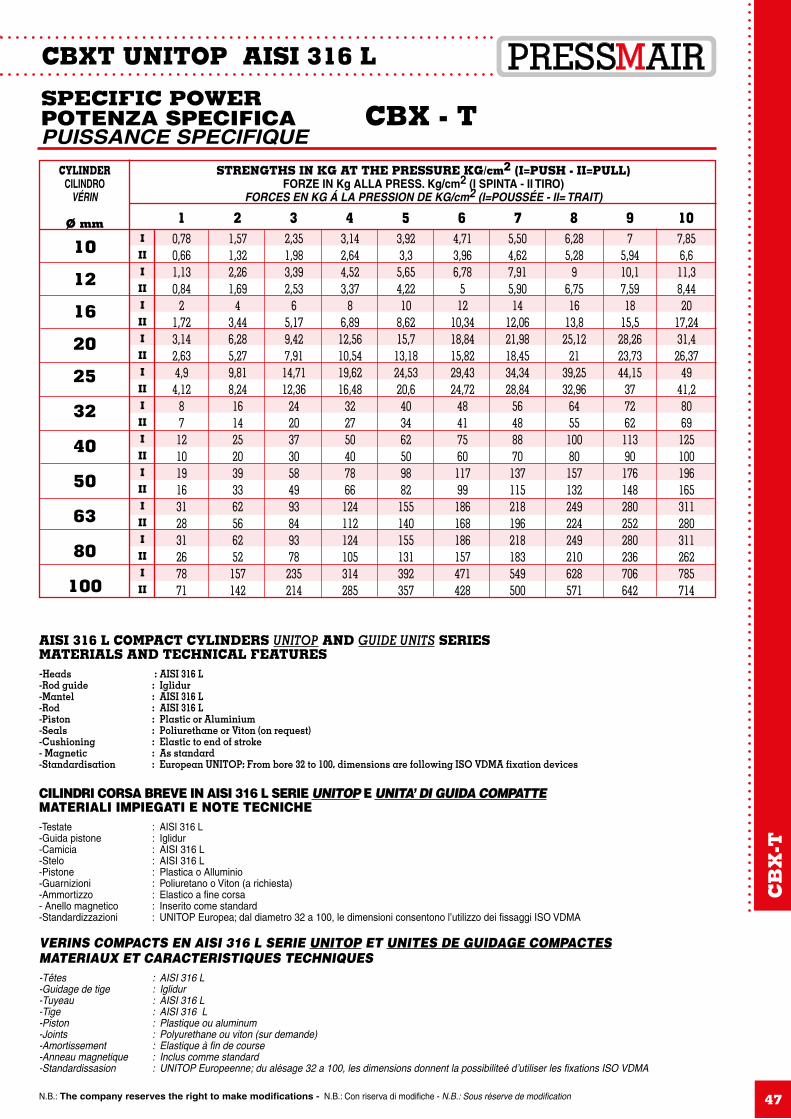
N.B.: The company reserves the right to make modifications - N.B.: Con riserva di modifiche - N.B.: Sous réserve de modification
CBXT UNITOP AISI 316 L
47
SPECIFIC POWERPOTENZA SPECIFICA CBX - TPUISSANCE SPECIFIQUE
STRENGTHS IN KG AT THE PRESSURE KG/cm2 (I=PUSH - II=PULL)FORZE IN Kg ALLA PRESS. Kg/cm2 (I SPINTA - II TIRO)
FORCES EN KG Á LA PRESSION DE KG/cm2 (I=POUSSÉE - II= TRAIT)
CYLINDERCILINDRO
VÉRIN
Ø mm 1 2 3 4 5 6 7 8 9 10
10
12
16
20
25
32
40
50
63
80
100
0,780,661,130,84
21,723,142,634,94,12
8712101916312831267871
1,571,322,261,69
43,446,285,279,818,2416142520393362566252157142
2,351,983,392,53
65,179,427,9114,7112,36
24203730584993849378235214
3,142,644,523,37
86,8912,5610,5419,6216,48
322750407866124112124105314285
3,923,35,654,2210
8,6215,713,1824,5320,6403462509882155140155131392357
4,713,966,78
512
10,3418,8415,8229,4324,72
4841756011799186168186157471428
5,504,627,915,9014
12,0621,9818,4534,3428,84
56488870137115218196218183549500
6,285,28
96,7516
13,825,12
2139,2532,96
645510080157132249224249210628571
75,9410,17,5918
15,528,2623,7344,15
37726211390176148280252280236706642
7,856,611,38,4420
17,2431,426,37
4941,28069125100196165311280311262785714
I
II
I
II
I
II
I
II
I
II
I
II
I
II
I
II
I
II
I
II
I
II
AISI 316 L COMPACT CYLINDERS UNITOP AND GUIDE UNITS SERIESMATERIALS AND TECHNICAL FEATURES-Heads : AISI 316 L-Rod guide : Iglidur-Mantel : AISI 316 L-Rod : AISI 316 L-Piston : Plastic or Aluminium-Seals : Poliurethane or Viton (on request)-Cushioning : Elastic to end of stroke- Magnetic : As standard-Standardisation : European UNITOP; From bore 32 to 100, dimensions are following ISO VDMA fixation devices
CILINDRI CORSA BREVE IN AISI 316 L SERIE UNITOP E UNITA’ DI GUIDA COMPATTEMATERIALI IMPIEGATI E NOTE TECNICHE-Testate : AISI 316 L-Guida pistone : Iglidur-Camicia : AISI 316 L-Stelo : AISI 316 L-Pistone : Plastica o Alluminio-Guarnizioni : Poliuretano o Viton (a richiesta)-Ammortizzo : Elastico a fine corsa- Anello magnetico : Inserito come standard-Standardizzazioni : UNITOP Europea; dal diametro 32 a 100, le dimensioni consentono l’utilizzo dei fissaggi ISO VDMA
VERINS COMPACTS EN AISI 316 L SERIE UNITOP ET UNITES DE GUIDAGE COMPACTESMATERIAUX ET CARACTERISTIQUES TECHNIQUES-Têtes : AISI 316 L-Guidage de tige : Iglidur-Tuyeau : AISI 316 L -Tige : AISI 316 L-Piston : Plastique ou aluminum-Joints : Polyurethane ou viton (sur demande)-Amortissement : Elastique à fin de course-Anneau magnetique : Inclus comme standard-Standardissasion : UNITOP Europeenne; du alésage 32 a 100, les dimensions donnent la possibiliteé d’utiliser les fixations ISO VDMA
CB
X-T
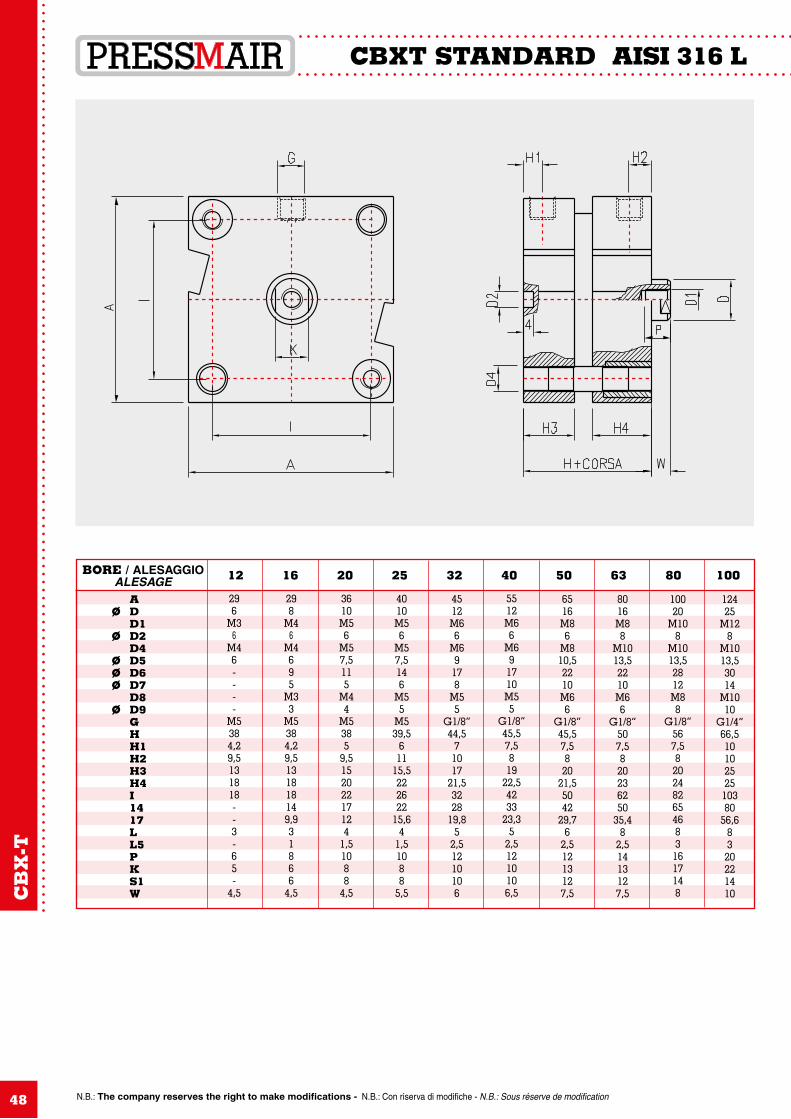
N.B.: The company reserves the right to make modifications - N.B.: Con riserva di modifiche - N.B.: Sous réserve de modification
CBXT STANDARD AISI 316 L
48
296
M36
M46----
M5384,29,5131818--3-65-
4,5
298
M46
M4695
M33
M5384,29,5131818149,931866
4,5
3610M56
M57,5115
M44
M5385
9,515202217124
1,51088
4,5
4010M56
M57,5146
M55
M539,5
611
15,5222622
15,64
1,51088
5,5
4512M66
M69178
M55
G1/8”44,5
71017
21,53228
19,85
2,51210106
5512M66
M691710M55
G1/8”45,57,5819
22,54233
23,35
2,51210106,5
6516M86
M810,52210M66
G1/8”45,57,5820
21,55042
29,76
2,51213127,5
8016M88
M1013,52210M66
G1/8”507,5820236250
35,48
2,51413127,5
10020
M108
M1013,52812M88
G1/8”567,582024826546831617148
12425
M128
M1013,53014
M1010
G1/4”66,51010252510380
56,68320221410
A Ø D D1 Ø D2 D4 Ø D5 Ø D6 Ø D7 D8 Ø D9 G H H1 H2 H3 H4 I 14 17 L L5 P K S1 W
BORE / ALESAGGIOALESAGE 12 16 20 25 32 40 50 63 80 100
CB
X-T
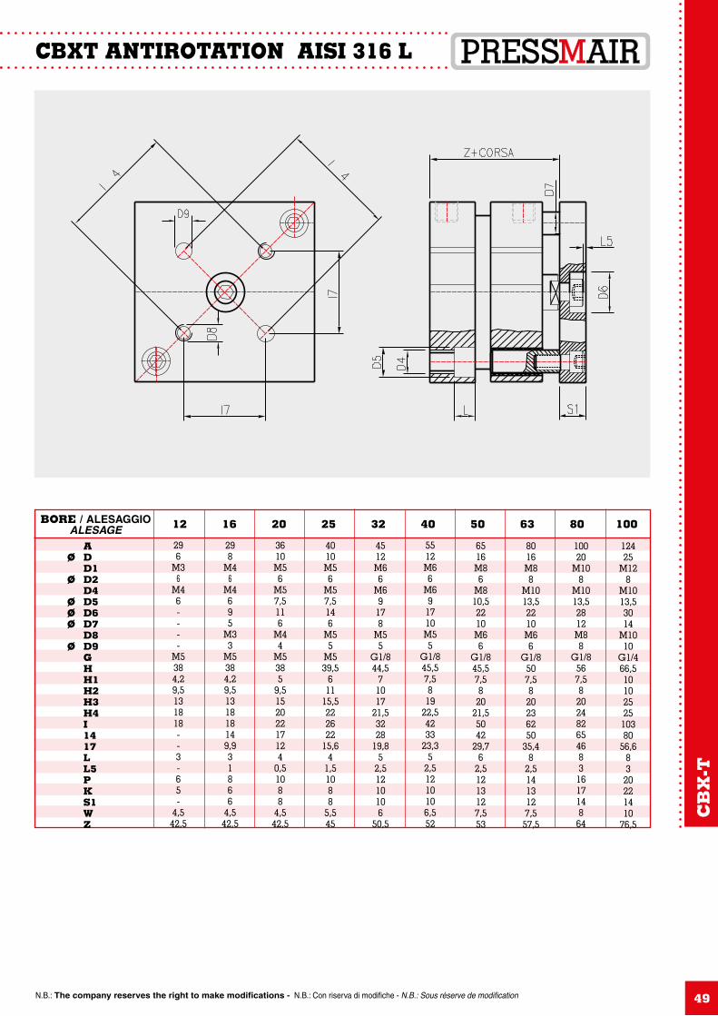
N.B.: The company reserves the right to make modifications - N.B.: Con riserva di modifiche - N.B.: Sous réserve de modification
CBXT ANTIROTATION AISI 316 L
49
296
M36
M46----
M5384,29,5131818--3-65-
4,542,5
298
M46
M4695
M33
M5384,29,5131818149,931866
4,542,5
3610M56
M57,5116
M44
M5385
9,515202217124
0,51088
4,542,5
4010M56
M57,5146
M55
M539,5
611
15,5222622
15,64
1,51088
5,545
4512M66
M69178
M55
G1/844,5
71017
21,53228
19,85
2,51210106
50,5
5512M66
M691710M55
G1/845,57,5819
22,54233
23,35
2,51210106,552
6516M86
M810,52210M66
G1/845,57,5820
21,55042
29,76
2,51213127,553
8016M88
M1013,52210M66
G1/8507,5820236250
35,48
2,51413127,557,5
10020
M108
M1013,52812M88
G1/8567,58202482654683161714864
12425
M128
M1013,53014
M1010
G1/466,51010252510380
56,68320221410
76,5
A Ø D D1 Ø D2 D4 Ø D5 Ø D6 Ø D7 D8 Ø D9 G H H1 H2 H3 H4 I 14 17 L L5 P K S1 W Z
BORE / ALESAGGIOALESAGE 12 16 20 25 32 40 50 63 80 100
CB
X-T
N.B.: The company reserves the right to make modifications - N.B.: Con riserva di modifiche - N.B.: Sous réserve de modification
INDEX
50
CUMX Pg. 5
CSX Pg. 13
CVX Pg. 31
CEAX Pg. 39
CBXT Pg. 45
N.B.: The company reserves the right to make modifications - N.B.: Con riserva di modifiche - N.B.: Sous réserve de modification 51
NOTES
N.B.: The company reserves the right to make modifications - N.B.: Con riserva di modifiche - N.B.: Sous réserve de modification52
NOTES