manufacturing of micro holes by using micro electric
TRANSCRIPT

MANUFACTURING OF MICRO HOLES BY USING
MICRO ELECTRIC DISCHARGE MACHINING
(MICRO-EDM)
A MASTER’S THESIS
in
Mechatronics Engineering
Atılım University
by
TAHSİN TECELLİ ÖPÖZ
JANUARY 2008

MANUFACTURING OF MICRO HOLES BY USING
MICRO ELECTRIC DISCHARGE MACHINING
(MICRO-EDM)
A THESIS SUBMITTED TO
THE GRADUATE SCHOOL OF NATURAL AND APPLIED SCIENCES
OF
ATILIM UNIVERSITY
BY
TAHSİN TECELLİ ÖPÖZ
IN PARTIAL FULFILLMENT OF THE REQUIREMENTS FOR THE DEGREE
OF
MASTER OF SCIENCE
IN
THE DEPARTMENT OF MECHATRONICS ENGINEERING
JANUARY 2008

I hereby declare that all information in this document has been obtained and
presented in accordance with academic rules and ethical conduct. I also declare that,
as required by these rules and conduct, I have fully cited and referenced all material
and results that are not original to this work.
Name, Last Name: Tahsin Tecelli ÖPÖZ
Signature:
iii
ABSTRACT
MANUFACTURING OF MICRO HOLES BY USING
MICRO ELECTRIC DISCHARGE MACHINING (MICRO-EDM)
ÖPÖZ, Tahsin Tecelli
M.S. in Mechatronics Engineering
Supervisor: Prof. Dr. Abdulkadir ERDEN
January 2008, 122 pages
Rapidly developing technology aims to develop products in miniaturized compact
volumes with more functions are embedded in the products and product components.
This requires advancement of micro manufacturing processes, hence industrial
research on micro-machining has become considerably important and widespread.
Manufacturing of micro holes by using Micro Electric Discharge Machining (Micro-
EDM) is one of the topics towards developing micro manufacturing technology. The
topic is investigated experimentally and extensively in this work.
There are many electrical and technological parameters of Micro-EDM process
which are decisive in the machining characteristics and affect geometrical shape and
surface quality of the machined parts. In this study, geometrical shapes of micro-
holes machined by micro-EDM with different machining parameters are
investigated. End tip shape formation, hole size expansion and hole wall-side
parallelism are examined in blind and through micro-hole manufacturing.
Consequently, destructive range of parameters which lead to defect formation inside
the hole are found to be due to long pulse duration ( >500 ns) together with higher
gain ( >15 ). In addition, entrance and exit diameters of through micro-holes are also
measured and experimental data are discussed. Conclusively over-travel of tool
electrode or secondary machining with a new electrode is recommended to obtain
iv

straighter walls and fine surface in micro-holes. Aspect ratios around 20 are obtained
easily by using tool electrode with a diameter equal to or less than 100 µm in blind
holes.
Progress of the machining is observed at the end tip of the tools and holes. Relation
between machining time and expected hole depth is studied and found to be
increasing with slowing rate. Another relation between machining time and hole
expansion in radial direction is also found to be a linear relation within defined band
width of 20 µm for hole diameter.
This thesis is aimed to contribute understanding of micro-EDM operating parameters
which are affecting on geometrical shape formation of micro-hole machining. We
may conclude that the hole manufacturer can predict the expected shape of micro-
hole in advance and save waste of time for sacrificial experiments.
Keywords: Micro Electric Discharge Machining (Micro-EDM), Micromachining,
Wire-Electric Discharge Grinding (WEDG), Micro-tool, Micro-hole, Electrode wear,
Material removal rate.
v
ÖZ
MİKRO ELEKTRİKSEL AŞINDIRMA İLE İŞLEME
KULLANARAK MİKRO DELİKLERİN ÜRETİMİ
ÖPÖZ, Tahsin Tecelli
Yüksek Lisans, Mekatronik Mühendisliği Bölümü
Tez Yöneticisi: Prof. Dr. Abdulkadir ERDEN
Ocak 2008, 122 sayfa
Hızla gelişen teknoloji, ürün ve parçaların daha fazla işlevsel fonksiyonlar ile
bütünleştirilmiş, boyutları küçültülmüş kompakt hacimlerdeki parçaların ve
aksamların geliştirilmesini amaçlamaktadır. Bu hedef doğrultusunda mikro imalat
yöntemlerinin geliştirilmesi gerekmektedir bundan dolayı mikro işleme üzerindeki
endüstriyel araştırmalar oldukça önemli olmakta ve yaygınlaşmaktadır. Mikro
elektriksel aşındırma ile mikro deliklerin üretimi mikro üretim teknolojisinin
geliştirilmesine yönelik konulardan biridir. Bu konu bu çalışmada deneysel olarak
geniş bir şekilde incelenmiştir.
Mikro elektriksel aşındırma ile işlemede, işlenen parçanın geometrik şeklini yüzey
kalitesini etkileyen, işleme karakteristiğini belirleyen, birçok elektriksel ve teknolojik
parametre bulunmaktadır. Bu çalışmada, mikro elektrik aşındırma ile işlenen mikro
deliklerin geometrik şekilleri farklı işleme parametreleri kullanılarak incelenmiştir.
Kör ve boydan delik delinmesinde, deliklerin son uç şekillerinin oluşumu, delik
çapında meydana gelen genişlemeler ve delik duvarlarının paralelliği araştırılmıştır.
Sonuç olarak, delik içinde geometrik bozulmalara uzun sinyal süreleri (>500 ns) ile
birlikte yüksek kazanım değerlerinin (<15) neden olduğu saptanmıştır. Ek olarak,
boydan mikro deliklerin giriş ve çıkış çapları ölçülmüş ve ölçüm verileri
değerlendirilmiştir. Bu değerlendirme sonucunda, daha düzgün duvar kenarları ve
daha az pürüzlü yüzey elde etmek için, deliğin açılmasından sonra elektrotun fazla
vi
vii
beslenmesi yada aşınmamış bir elektrot ile yeniden işleme tavsiye edilmiştir. Kör
deliklerde 100 µm lik yada daha küçük çaplı elektrotlar kullanarak 20 boy/çap
oranına erişilmiştir.
Elektrotlarda ve deliklerde oluşan uç şekil gelişimi gözlemlenmiştir. İşleme süresi ve
bu işleme süresine karşılık delik derinliği arasındaki ilişkisel bağ üzerinde çalışılmış
ve işleme süresi arttıkça delik derinliğinde oransal azalma olduğu bulunmuştur.
İşleme süresi ve deliğin radyal yönde genişlemesi arasındaki bir diğer ilişki de delik
çapı için 20 µm lik bir bant içerisinde doğrusal olarak değiştiği bulunmuştur.
Bu tezde mikro elektriksel aşındırma ile mikro deliklerin işlenmesinde, işleme
parametrelerinin mikro delik geometrisi üzerindeki etkilerinin anlaşılmasına katkıda
bulunulması amaçlanmıştır. Böylelikle, elde edilen bulgularla, üreticiler mikro
deliğin şeklini, birçok uzun ve maliyetli deneyler yapmadan, tahmin edebilecektir.
Anahtar Kelimeler: Mikro-Elektriksel Aşındırma ile İşleme (Mikro-EDM), Mikro-
işleme, Tel Elektrik Aşındırma (WEDG), Mikro Elektrot, Mikro delik, Elektrot
aşınması, Malzeme kaldırma hızı.

To My Parents
viii

ix
ACKNOWLEDGEMENTS
The author wishes to express his deepest gratitude to Prof. Dr. Abdulkadir ERDEN
for his advice, criticism and encouragement during the investigation and fulfillment
of this study.
The author also would like to thank Dr. Bülent EKMEKÇİ for his invaluable advice
and criticism and also his great effort during the metallographic preparation of test
specimen in Zonguldak Karaelmas University.
The author wishes to thank Dr. H. Selçuk HALKACI, Dr. Fuad ALİEW, Dr. Bülent
İRFANOĞLU, Dr. Zuhal ERDEN, Inst. Kutluk Bilge ARIKAN and Inst. Aylin K.
EROĞLU for their suggestions and comments.
Also, the author would like to thank Emrah DEMİRCİ, Alper GÜNER and M. Burcu
BİLDİRGEN for their supports and friendship during my study.
I would like to offer my great thanks to my parents for their endless supports and
patience.
This thesis is fulfilled within the context of the research project entitled
“Development and implementation of micro machining (especially micro-EDM)
methods to produce (design and manufacture) of mini/micro machines/robots”;
funded by the State Planning Organization of Turkey (DPT). The author
acknowledges the contributions of the main funding organization; State Planning
Organization of Turkey (DPT) and the other supporting organization Atılım
Univestiy.

TABLE OF CONTENTS
ABSTRACT..................................................................................................... iv
ÖZ ....................................................................................................... vi
ACKNOWLEDGEMENT ............................................................................... ix
TABLE OF CONTENTS................................................................................. x
LIST OF TABLES ........................................................................................... xii
LIST OF FIGURES ......................................................................................... xiii
LIST OF ABBREVIATIONS.......................................................................... xviii
CHAPTER
1. INTRODUCTION ........................................................................ 1
1.1. Background of Electrical Discharge Machining.................. 2
1.2. Basic Principles of Micro Electrical Discharge Machining 4
1.3. Wire-Electric Discharge Grinding Process.......................... 6
1.4. Start-up micro-EDM Research Laboratory ......................... 8
1.5. Applications of micro-EDM ................................................ 9
1.6. Scope of the Thesis .............................................................. 11
2. LITERATURE SURVEY ............................................................. 13
2.1 Existing Micro-EDM Systems............................................. 13
2.2 Material Removal of micro-EDM ....................................... 15
2.3 Tool Electrode Manufacturing and Wear in micro-EDM.... 17
2.4 2D&3D Machining by micro-EDM..................................... 21
2.5 Micro hole Machining by Varying micro-EDM
Specifications....................................................................... 23
x
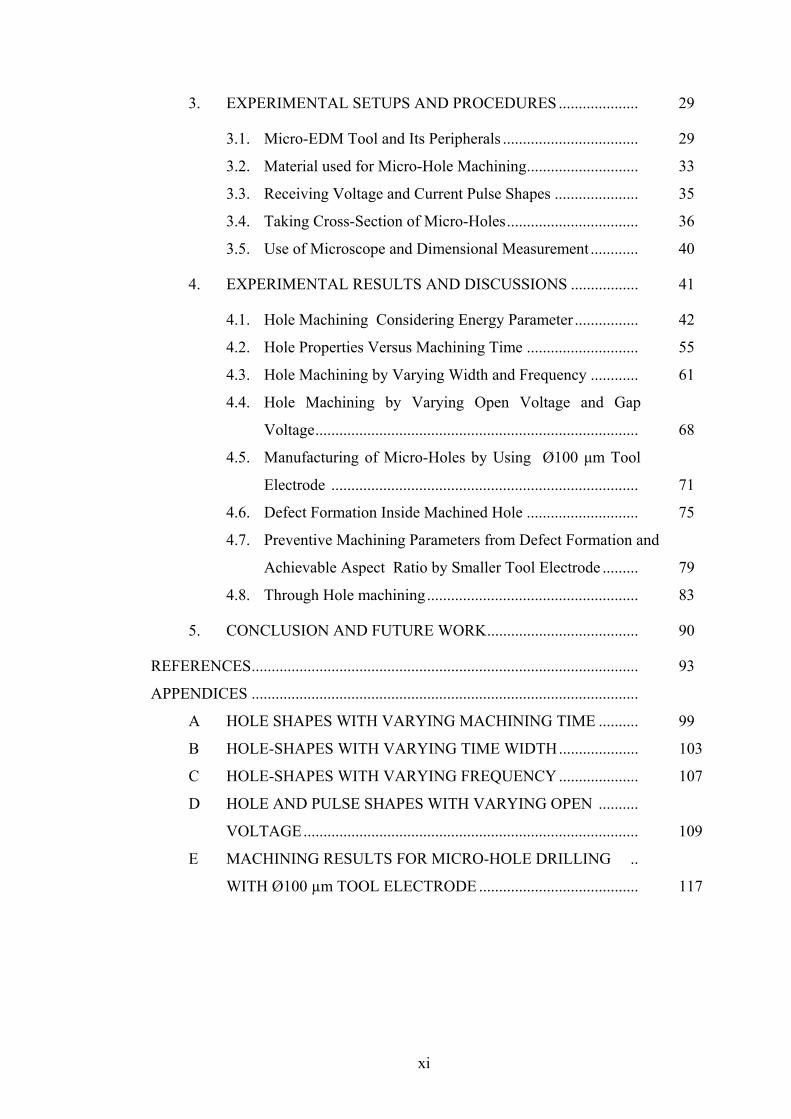
3. EXPERIMENTAL SETUPS AND PROCEDURES .................... 29
3.1. Micro-EDM Tool and Its Peripherals .................................. 29
3.2. Material used for Micro-Hole Machining............................ 33
3.3. Receiving Voltage and Current Pulse Shapes ..................... 35
3.4. Taking Cross-Section of Micro-Holes................................. 36
3.5. Use of Microscope and Dimensional Measurement ............ 40
4. EXPERIMENTAL RESULTS AND DISCUSSIONS ................. 41
4.1. Hole Machining Considering Energy Parameter ................ 42
4.2. Hole Properties Versus Machining Time ............................ 55
4.3. Hole Machining by Varying Width and Frequency ............ 61
4.4. Hole Machining by Varying Open Voltage and Gap
Voltage................................................................................. 68
4.5. Manufacturing of Micro-Holes by Using Ø100 μm Tool
Electrode ............................................................................. 71
4.6. Defect Formation Inside Machined Hole ............................ 75
4.7. Preventive Machining Parameters from Defect Formation and
Achievable Aspect Ratio by Smaller Tool Electrode ......... 79
4.8. Through Hole machining..................................................... 83
5. CONCLUSION AND FUTURE WORK...................................... 90
REFERENCES................................................................................................. 93
APPENDICES .................................................................................................
A HOLE SHAPES WITH VARYING MACHINING TIME .......... 99
B HOLE-SHAPES WITH VARYING TIME WIDTH.................... 103
C HOLE-SHAPES WITH VARYING FREQUENCY .................... 107
D HOLE AND PULSE SHAPES WITH VARYING OPEN ..........
VOLTAGE.................................................................................... 109
E MACHINING RESULTS FOR MICRO-HOLE DRILLING ..
WITH Ø100 µm TOOL ELECTRODE ........................................ 117
xi
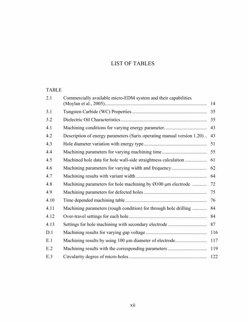
LIST OF TABLES TABLE 2.1 Commercially available micro-EDM system and their capabilities
(Moylan et al., 2005).................................................................................... 14
3.1 Tungsten Carbide (WC) Properties.............................................................. 35
3.2 Dielectric Oil Characteristics....................................................................... 35
4.1 Machining conditions for varying energy parameter................................... 43
4.2 Description of energy parameters (Sarix operating manual version 1.20) .. 43
4.3 Hole diameter variation with energy type.................................................... 51
4.4 Machining parameters for varying machining time..................................... 55
4.5 Machined hole data for hole wall-side straightness calculation .................. 61
4.6 Machining parameters for varying width and frequency............................. 62
4.7 Machining results with variant width .......................................................... 64
4.8 Machining parameters for hole machining by Ø100 μm electrode ............ 72
4.9 Machining parameters for defected holes .................................................... 75
4.10 Time depended machining table ................................................................... 76
4.11 Machining parameters (rough condition) for through hole drilling ............ 84
4.12 Over-travel settings for each hole ................................................................ 84
4.13 Settings for hole machining with secondary electrode ................................ 87
D.1 Machining results for varying gap voltage .................................................. 116
E.1 Machining results by using 100 µm diameter of electrode.......................... 117
E.2 Machining results with the corresponding parameters ................................ 119
E.3 Circularity degree of micro-holes ................................................................ 122
xii

LIST OF FIGURES FIGURES 1.1 The gap current and gap voltage for four types of discharges seen in the
EDM process (Rajurkar, 1987) ...................................................................... 3
1.2 Proposed model of breakdown phase. (a) Emission of prebreakdown current and heating at micro peaks. (b) Bubble nucleation at micro-peak. (c) Reaching electron impact criteria at bubble interface. (d) Bubble elongation towards anode. (e) Bubble abridged the interelectrode gap and fully developed plasma channel at the end of the breakdown phase (Dhanik and Joshi, 2005) ............................................................................... 6
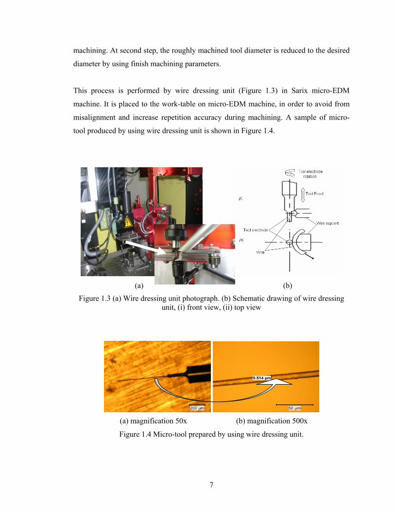
1.3 (a) Wire dressing unit photograph, (b) Schematic drawing of wire dressing unit (i) front view, (ii) top view ....................................................... 7
1.4 Micro-tool prepared by using wire dressing unit ....................................... 7
1.5 An overall picture of the micro-EDM laboratory .......................................... 8
1.6 Sample of micro-EDM products which are named as in (a) Nozzle for diesel injectors (b) Plastic gear for watches (c) Micro-gear die with outer diameter around 600 µm and depth of 100 µm (d) A letter of ‘mekatronik’ and ‘M’ are machined by contouring process, (e) Micro-channels with a depth of 1 mm by using 400 µm-diameter circular electrode, (f) Department of Mechatronics Engineering Logo machined on a metal plate with a depth of 100 µm. Products in c, d, e, and f are machined by using Sarix micro-EDM machine in Atılım University Laboratory .... 9
2.1 Single discharge RC-circuit of micro-EDM (Wong et al., 2003) .................. 16
2.2 Principle of WEDG with one wire guide (Fleischer, 2004)........................... 18
2.3 Principle of obtaining micro-rod (Yamazaki et al., 2004) ............................. 18
2.4 (a) SEM image of a copper structure with a gear shape as a machining electrode, (b) SEM image of EDMed workpiece by the electrode shown in (a) (Takahata et al., 1999) .............................................................................. 19
2.5 (a) Shape of micro-hole by tubular electrode (b) Shape of micro-hole by rod electrode (Pham et al., 2007) ................................................................... 20
xiii

2.6 (a) Cu electrode arrays with patterned interconnect fabricated by using LIGA technique with two-mask alignment sequence, (b) WC-Co super hard alloy gears cut from 70-µm thick workpiece using electrode arrays of (a) (Takahata and Gianchandani, 2002) ......................................................... 23
2.7 Section view of a single-notch electrode (Wansheng et al., 2002) ................ 25
2.8 Schematic diagrams of four methods micro-hole micro-EDM drilling (a) using cylinder electrode for micro-EDM, (b) using cylinder electrode for micro-EDM combined with ultrasonic vibration, (c) using a helical micro-tool electrode for micro-EDM and (d) using a helical micro-tool electrode for micro-EDM combined with ultrasonic vibration (Hung et al., 2006) .............................................................................................................. 26
2.9 (a) Triangular blind hole (b) square blind hole (c) pentagonal blind hole (Yu et al., 2002). ............................................................................................ 27
3.1 Schematic drawing of micro-EDM system.................................................... 29
3.2 Micro-EDM machine. .................................................................................... 31
3.3 Wire dressing unit and optical microscope with 125x magnification lens .... 31
3.4 Spark observation during machining ............................................................. 32
3.5 Electrode dressing by wire dressing unit ....................................................... 32
3.6 A sample of drilled micro-holes with a Ø100 µm tool electrode................... 33
3.7 Flowchart for the experimental processes...................................................... 33
3.8 Sample of plastic mold steel (70x10x2) used for micro-EDM ...................... 34
3.9 Tool electrodes and low resistance resistor.................................................... 34
3.10 Agilent 54621D Mixed Signal Oscilloscope 60MHz, 200Msa/sec. .............. 36
3.11 Buehler precision isomet low speed saw. ...................................................... 37
3.12 Automatic hot mounting press ....................................................................... 38
3.13 Grinding and Polishing machine.................................................................... 38
3.14 A sample of specimen .................................................................................... 39
3.15 Overall pictures of metallographic machines used in the specimen preparation ..................................................................................................... 39
3.16 Nikon microscope and digital camera............................................................ 40
4.1 Voltage (upper case) and current (lower case) pulse form for energy level of 350 (a) two pulse (b) one pulse.................................................................. 44
4.2 Voltage (upper case) and current (lower case) pulse form for energy level of 305 (a) squashed time scale (b) extended time scale ................................. 45
4.3 Voltage (upper case) and current (lower case) pulse form for energy level of 250 (a) squashed time scale (b) extended time scale ................................. 46
xiv
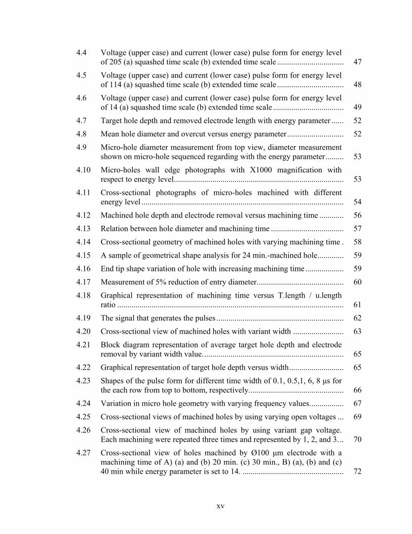
4.4 Voltage (upper case) and current (lower case) pulse form for energy level of 205 (a) squashed time scale (b) extended time scale ................................. 47
4.5 Voltage (upper case) and current (lower case) pulse form for energy level of 114 (a) squashed time scale (b) extended time scale ................................. 48
4.6 Voltage (upper case) and current (lower case) pulse form for energy level of 14 (a) squashed time scale (b) extended time scale ................................... 49
4.7 Target hole depth and removed electrode length with energy parameter ...... 52
4.8 Mean hole diameter and overcut versus energy parameter............................ 52
4.9 Micro-hole diameter measurement from top view, diameter measurement shown on micro-hole sequenced regarding with the energy parameter......... 53
4.10 Micro-holes wall edge photographs with X1000 magnification with respect to energy level.................................................................................... 53
4.11 Cross-sectional photographs of micro-holes machined with different energy level .................................................................................................... 54
4.12 Machined hole depth and electrode removal versus machining time ............ 56
4.13 Relation between hole diameter and machining time .................................... 57
4.14 Cross-sectional geometry of machined holes with varying machining time . 58
4.15 A sample of geometrical shape analysis for 24 min.-machined hole............. 59
4.16 End tip shape variation of hole with increasing machining time ................... 59
4.17 Measurement of 5% reduction of entry diameter........................................... 60
4.18 Graphical representation of machining time versus T.length / u.length ratio ................................................................................................................ 61
4.19 The signal that generates the pulses ............................................................... 62
4.20 Cross-sectional view of machined holes with variant width ......................... 63
4.21 Block diagram representation of average target hole depth and electrode removal by variant width value...................................................................... 65
4.22 Graphical representation of target hole depth versus width........................... 65
4.23 Shapes of the pulse form for different time width of 0.1, 0.5,1, 6, 8 μs for the each row from top to bottom, respectively............................................... 66
4.24 Variation in micro hole geometry with varying frequency values................. 67
4.25 Cross-sectional views of machined holes by using varying open voltages ... 69
4.26 Cross-sectional view of machined holes by using variant gap voltage. Each machining were repeated three times and represented by 1, 2, and 3. .. 70
4.27 Cross-sectional view of holes machined by Ø100 μm electrode with a machining time of A) (a) and (b) 20 min. (c) 30 min., B) (a), (b) and (c) 40 min while energy parameter is set to 14. .................................................. 72
xv

4.28 Cross-sectional view of holes machined by Ø100 μm electrode with a machining time of 60 min. and energy parameter for a) 14, b) 105 and c) 114.................................................................................................................. 74
4.29 Cross-sectional view of holes machined by Ø100 μm electrode with a machining time of 15 min. and energy parameter of 350 for a, b, and c. ...... 74
4.30 A series of hole machining defectively (numbers assigned to each pictures are given considering total machined holes as given in Appendix F)............ 76
4.31 Defective hole shape labeled with (4-1)......................................................... 77
4.32 SEM photographs of defective hole from top view ....................................... 76
4.33 Recorded pulse forms of defective hole in Figure 4.31 with instant machining time shown under the captured pulse shapes. .............................. 77
4.34 Cross-sectional views of defective and smooth machined holes ................... 80
4.35 Cross-sectional views of machined micro-holes............................................ 81
4.36 Micro-holes to show circularity, label in the bottom of each picture represent hole number, electrode size, machining time and microscopic magnification, respectively ............................................................................ 82
4.37 Schematic views of (a) tapered shape hole and (b) exactly cylindrical shape hole (Hung et al., 2006). ...................................................................... 83
4.38 Schematic illustration of electrode over-travel to avoid from tapered shape (a) Worn tip of rod electrode causes a narrower hole exit and (b) enlarged hole exit is generated due to the over-travel of rod electrode ........................ 84
4.39 Machined hole entrance and exit diameter pictures by applying electrode over-travel. ..................................................................................................... 85
4.40 Entrance and exit diameter photos of holes machined by using two electrodes. ...................................................................................................... 88
A.1 Micro-holes cross-sectional shape with different machining time from 1min. to 80 min. and constant machining parameters as given in Table 4.4................................................................................................................... 99
B.1 Micro-hole photographs from top view by using variant width time ............ 103
B.2 Cross-sectional photographs of micro-holes by using variant width time..... 105
C.1 Micro hole photographs machined with different frequency values of 10 kHz, 25 kHz, 50 kHz, 100 kHz, and 150 kHz r for each row, respectively... 107
D.1 Machined hole photos by setting gap voltage 50 V and gradually increasing open voltage value as given beneath the related pictures. 1000x magnified pictures of each holes are also illustrated to discuss the quality of the hole wall surface with varying open voltage value.............................. 109
D.2 Captured Pulse form for different open voltage values ................................. 111
xvi

xvii
D.3 Machined hole pictures from top view and 1000x magnified edge view with different gap voltage value and constant open voltage at 100V. ........... 113
D.4 Voltage and current pulse forms for different gap voltage while open voltage kept constant at 100V........................................................................ 114
E.1 Pulse shapes for 100 µm diameter of electrode by using energy parameter 350 and 14 ..................................................................................................... 118
E.2 Micro-hole pictures for determining circularity with the magnified view represented under each picture....................................................................... 120

LIST OF ABBREVIATIONS
EDM Electric Discharge Machining MEMS Micro-Electro Mechanical Systems EBM Electron Beam Machining ECM Electro Chemical Machining MUSM Micro Ultrasonic Machining LBM Laser Beam Machining WEDG Wire-Electric Discharge Grinding 3D Three-Dimensional 2D Two-Dimensional CAD Computer-Aided Design CAM Computer-Aided Manufacturing MRM Material Removal Mechanism PWM Pulse-Width Modulation MRR Material Removal Rate CNC Computer Numerical Control DVEE Diameter Variations between Entrance and Exit WC Tungsten Carbide GPIB General Purpose Interface Bus STD Standard Deviation
xviii
CHAPTER 1
INTRODUCTION
Miniaturization of parts and components play an important role in the development of
today’s and future’s sophisticated technology in various fields. With the increasing
demand for micro parts and structures in many industries, and also with rapid
developments in micro-electro-mechanical systems (MEMS), micro manufacturing
techniques for producing these parts become increasingly important. Micro structures
including micro holes, micro slots, micro shafts, and micro gears are mostly used micro
products needed in industry. Especially micro holes are needed in optical devices,
medical instruments and automobile engine parts (Masuzawa, 2000, Kim et al., 2006).
Currently micro holes are formed by different manufacturing methods including micro
electrical discharge machining (micro-EDM), electron beam machining (EBM), laser
machining, etching, electro chemical machining (ECM), micro-ultrasonic machining
(MUSM), micro mechanical drilling, micro punching, (Masuzawa, 2000, Kim et al.,
2006, Kaminski and Capuano, 2003, Takahata and Gianchandani, 2002, Her and Weng,
2001, Yu et al., 2002, Diver et al., 2004, Yan et al., 2002). The selection of appropriate
micromachining technique mainly depends on the type of material, size and shape of
feature, aspect ratios (in the case of micro hole), cost of process etc. For example, laser
beam machining (LBM) can be used to drill a hole under diameter of 4µm, however, it
causes deterioration and micro cracks on the machined surface. ECM can improve the
material removal rate to 1.5 mm/min and surface roughness to 0.008 µm, however, the
walls of the micro-holes are over etched. Microelectronic processing technologies such
as photolithography and etching are not suitable to machine micro features on metallic
alloys.
1

Mechanical manufacturing methods such as drilling can be used to drill holes of 70 µm
in diameter. Laser has the ability of drilling holes of 40 µm with the possible aspect
ratios of around 10 for metallic materials (Yu et al., 2002). However, with these
methods, besides cost aspect, it is very difficult to drill a high aspect ratio or a blind
noncircular micro hole with sharp corners and edges with super alloys such as stainless
steel and tungsten carbide. Among of these micromachining techniques, micro-EDM is
mainly preferred where the high aspect ratio, high surface integrity and low cost are
required on any conductive material regardless of its hardness. Micro-EDM has
successfully been applied to machine micro-holes of 5 µm and also 3D complex cavities
(Masuzawa, 2000).
1.1 Background of Electrical Discharge Machining
Electrical discharge machining (EDM) is a thermal material removal process by melting
and, partially, vaporization of the workpiece material. Source of the energy used for
melting and vaporization is found in the form of heat, generated by electrical discharges
and sparks between two electrodes in close proximity. The electrodes (tool electrode and
workpiece) are immersed in dielectric liquid or flowing pressurized dielectric medium.
Electrical discharge occurs when the dielectric is broken down by the application of
voltage pulse. Some of the released energy during discharge is transferred to the
electrodes and results in the heating of highly localized regions of the electrodes. When
the temperature of the heating region exceeds melting temperature of the electrodes,
material removal starts in size of very small particles. Molten and/or vaporized particles
(debris material) are washed away from the sparking area by the continuously flushing
dielectric fluid. Flowing pressure of the dielectric fluid should be used in an appropriate
value, high pressurized fluid result in vanishing the influence of electrical sparks, and
removed together with debris particles, however, low pressure flow result in rising
debris concentration in sparking area and cause secondary discharge, arc, and short
circuit.
2

In EDM process, mechanical properties of the workpiece do not affect the machining
process. Thermal properties such as melting point, boiling point, and electrical
conductivity of workpiece materials affect the machining characteristics. The material
removal rate of EDM process is primarily determined by the electrical conductivity and
melting temperature of the workpiece material. A workpiece with higher electrical
conductivity and lower melting temperature can be machined more efficiently (Qu,
2002).
Four possible discharge types occur in conventional EDM process (hereafter
conventional EDM stands for ram type EDM or die-sinking EDM). They are illustrated
and named in Figure 1.1. The first one is the open circuit state, actually it is not a
discharge, but it is the prerequisite for ‘spark’ good discharge. The third and the last one,
‘arc’ and ‘short’ respectively, are undesired discharges, they adversely affect the
machining efficiency and surface roughness. Type of pulses in micro-EDM is different
from that of conventional EDM. This is caused mostly by the type of circuit used in
pulse generator and its advance control mechanism, additional information about type of
micro-EDM pulse is given in forthcoming chapters.
Figure 1.1 The gap current and gap voltage for the four types of discharges seen in the
EDM process (Rajurkar, 1987).
3

1.2 Basic Principles of Micro Electrical Discharge Machining
Micro electrical discharge machining (micro-EDM) is a derived form of EDM, which is
generally used to manufacture micro and miniature parts and components by using the
conventional electrical discharge machining principles. Similar to conventional EDM,
material is removed by a series of rapidly recurring electric spark discharges between the
tool electrode and the workpiece in micro-EDM. Actually main differences of micro-
EDM from conventional EDM are being in the type of pulse generator, the resolution of
the X-, Y- and Z- axes movement, and the size of the tool used. In micro-EDM; pulse
generator produces very small pulses within pulse duration of a few micro seconds or
nano seconds. Because of this reason, micro-EDM utilizes low discharge energies
(~ joules) to remove small volumes (~ μm ) of material
(Moylan et al., 2005). The most important factor which makes micro-EDM very
important in micromachining is its machining ability on any type of conductive and
semi-conductive materials with high surface accuracy irrespective of material hardness.
It is preferred especially for the machining of difficult-to-cut material due to its high
efficiency and precision.
59 1010 −− − 50005.0 − 3
Small volumetric material removal of micro-EDM provides substantial opportunities for
manufacturing of micro-dies and micro-structure such as micro holes, micro slot, and
micro gears etc. The use of micro-EDM has many advantages in micro-parts, the main
advantage is that it can machine complex shapes into any conductive material with very
low forces. The forces are very small because the tool and the workpiece do not come
into contact during the machining process. This property provides advantages to both the
tool and the workpiece. For example, in EDM, a very thin tool can be used because it
will not be bent by the machining force. The other advantages of micro-EDM include
low set-up cost, high aspect ratio, enhanced precision and large design freedom. In
addition, EDM does not make direct contact between the tool electrode and workpiece
material, hence eliminating mechanical stress, chatter and vibration problems during
machining. Therefore, relying on the above advantages, micro-EDM is very effective to
4

machine any kind of holes such as small diameter holes down to 10 µm and blind holes
with 20 aspect ratio.
Although micro-EDM is a very efficient process in micro hole machining and having
many advantages, it has also some disadvantages. One of them is that it is a rather slow
machining process; the other is that while the workpiece electrode is being machined,
the tool electrode also wears at a rather significant rate. This tool-wear leads to shape
inaccuracies. Another drawback is the formation of a heat affected layer on the
machined surface. Since it is impossible to remove all the molten part of the workpiece,
a thin layer of molten material remains on the workpiece surface, which re-solidifies
during cooling (Masuzawa, 2000).
The theoretical and physical model of conventional EDM with its basic elements were
discussed and explored with all details in PhD thesis (Erden, 1977 and Ekmekçi, 2004).
Physical model developed for micro-EDM is slightly different from that of conventional
EDM. The use of resistance capacitance pulse generator, an advanced controller for
machining in smaller interelectrode gaps and with lower discharge energies than in
EDM, makes the material removal characteristics of a single discharge in micro-EDM
different from that of the EDM (Dhanik and Joshi, 2005). In Figure 1.2, breakdown
phase of single discharge model in micro-EDM is demonstrated. In EDM, breakdown of
liquid dielectric leads to the formation of a plasma channel between the electrodes. The
plasma expands and interacts with electrodes to effect the material removal from the
respective electrodes.
Another significant point of micro-EDM is the inverted polarity of the tool electrode.
Due to polarity effect in conventional EDM with long pulse duration, the tool electrode
is usually charged as anode to increase material removal rate and to reduce electrode
wear. At short pulse durations as used in micro-EDM, this effect is reversed. Therefore,
in micro-EDM, the tool electrode is usually charged as cathode (Uhlmann et al., 2005).
5

Figure 1.2 Proposed model of breakdown phase. (a) Emission of prebreakdown current and heating at micro peaks. (b) Bubble nucleation at micro-peak. (c) Reaching electron
impact criteria at bubble interface. (d) Bubble elongation towards anode. (e) Bubble abridged the interelectrode gap and fully developed plasma channel at the end of the
breakdown phase (Dhanik and Joshi, 2005).
Micro-EDM can be used as variant machining processes; they are micro-ED drilling,
micro-ED milling, micro-ED die sinking, micro-ED contouring, micro-ED dressing, and
micro wire electrical discharge grinding (micro-WEDG). All of these processes are
integrated in a today’s sophisticated micro-EDM machines.
1.3 Wire-Electric Discharge Grinding Process
Wire-Electric Discharge Grinding (WEDG) (Masuzawa et al., 1985) is a prerequisite
machining for drilling micro-holes and milling micro-cavities with micro-EDM
technology. WEDG is used to prepare smaller size tool down to Ø10 µm by using
electrical discharge machining principle with reverse polarity. Smaller size tool is
prepared from larger tools. This process can be divided into two steps. At first step, the
diameter of larger tool is reduced to nearly the desired smaller diameter by rough
6
machining. At second step, the roughly machined tool diameter is reduced to the desired
diameter by using finish machining parameters.
This process is performed by wire dressing unit (Figure 1.3) in Sarix micro-EDM
machine. It is placed to the work-table on micro-EDM machine, in order to avoid from
misalignment and increase repetition accuracy during machining. A sample of micro-
tool produced by using wire dressing unit is shown in Figure 1.4.
(a) (b)
Figure 1.3 (a) Wire dressing unit photograph. (b) Schematic drawing of wire dressing unit, (i) front view, (ii) top view
(a) magnification 50x (b) magnification 500x
Figure 1.4 Micro-tool prepared by using wire dressing unit.
7
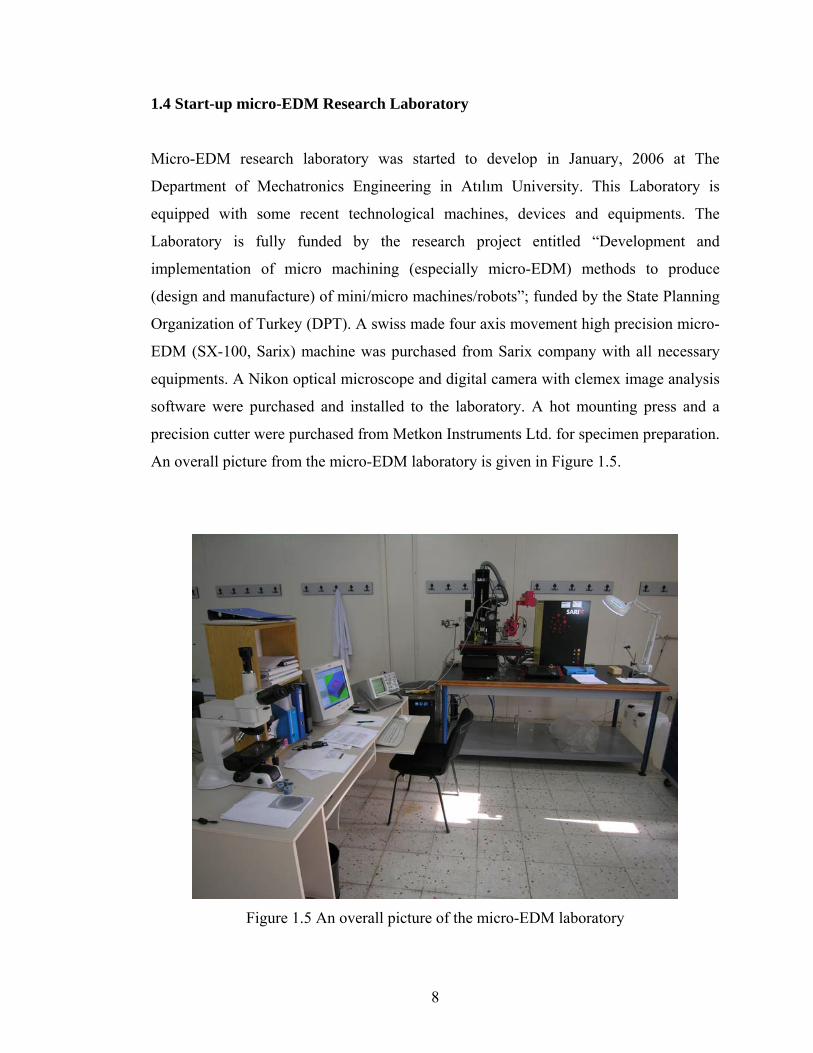
1.4 Start-up micro-EDM Research Laboratory
Micro-EDM research laboratory was started to develop in January, 2006 at The
Department of Mechatronics Engineering in Atılım University. This Laboratory is
equipped with some recent technological machines, devices and equipments. The
Laboratory is fully funded by the research project entitled “Development and
implementation of micro machining (especially micro-EDM) methods to produce
(design and manufacture) of mini/micro machines/robots”; funded by the State Planning
Organization of Turkey (DPT). A swiss made four axis movement high precision micro-
EDM (SX-100, Sarix) machine was purchased from Sarix company with all necessary
equipments. A Nikon optical microscope and digital camera with clemex image analysis
software were purchased and installed to the laboratory. A hot mounting press and a
precision cutter were purchased from Metkon Instruments Ltd. for specimen preparation.
An overall picture from the micro-EDM laboratory is given in Figure 1.5.
Figure 1.5 An overall picture of the micro-EDM laboratory
8

1.5 Applications of micro-EDM
Machining capability of micro-EDM, in conductive materials with high precision
regardless of material hardness, create a wide range of application area with the
increasing demand for miniaturized parts and components such as holes, nozzles, and
gears. Produced micro parts by micro-EDM are widely used in micro-electro-mechanical
systems (MEMS), biomedical applications, automotive industry, and defense industry.
Several typical components are manufactured using micro-EDM. Although the main
research is going on micro-hole manufacturing, different shape of three-dimensional
(3D) and two-dimensional (2D) cavities are also machined to demonstrate the machining
capability of micro-EDM. A CAD/CAM system is used to generate tool paths of 3D and
2D micro-parts. Commercially available Catia V5 and Esprit CAM software are used to
meet this requirement. Sample of micro-EDM products are demonstrated in Figure 1.6.
Ø magnet shaft 0.350 mm
hole Ø 0.10 mm depth 1/1.4 mm
(a) Nozzle for diesel injectors (b) Plastic gear for watches (http://www.sarix.com/) (http://www.sarix.com/)
Figure 1.6 Sample of micro-EDM products which are named as in a, b, c, d, e, and f. Products in c, d, e, and f are machined by using Sarix micro-EDM machine in Atılım
University Laboratory (cont.).
9
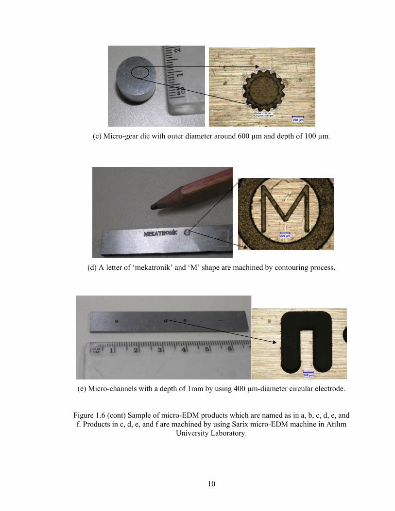
(c) Micro-gear die with outer diameter around 600 µm and depth of 100 µm.
(d) A letter of ‘mekatronik’ and ‘M’ shape are machined by contouring process.
(e) Micro-channels with a depth of 1mm by using 400 µm-diameter circular electrode.
Figure 1.6 (cont) Sample of micro-EDM products which are named as in a, b, c, d, e, and f. Products in c, d, e, and f are machined by using Sarix micro-EDM machine in Atılım
University Laboratory.
10

(f) Department of Mechatronics Engineering Logo machined on a metal plate with a
depth of 100 µm.
Figure 1.6 (cont) Sample of micro-EDM products which are named as in a, b, c, d, e, and f. Products in c, d, e, and f are machined by using Sarix micro-EDM machine in Atılım
University Laboratory.
1.6 Scope of the Thesis
In micro-EDM, machining characteristics primarily based on electrical and
technological parameters such as current, voltage, pulse duration, pulse width,
frequency, etc and material properties such as electrical conductivity, melting point,
heat capacitance, etc. Especially electrical parameters play an important role in
determining the machining accuracy, surface precision, and surface finish.
In this thesis, geometrical shape formations of micro-holes by varying machining
parameters of micro-EDM are investigated. Influences of machining parameters and tool
electrode size on the shape formation of micro-hole are reported. Moreover, achievable
aspect ratios, straightness of hole wall-side, electrode wear, and material removal rate
are also investigated and discussed. Therefore, optimal parameters to drill micro-holes in
desired shape is investigated by considering several micro-hole machining experiments.
With the result of this study, obtained geometrical shape of micro holes, aspect ratios,
side wall straightness, depth/machining time demonstrate the achievable machining limit
using state-of-the-art micro-EDM technology. Micro-EDM user can predict the
11
12
geometry and size of micro-holes machined by using micro-EDM when the
recommended machining parameters and materials are used.
Besides chapter 1, in chapter 2, a literature survey on micro-holes machined by micro-
EDM process is presented. Additional systems and mechanisms integrated to the micro-
EDM to increase machining quality and to obtain higher aspect ratios are also presented.
In chapter 3, experimental set-ups and procedure is given. Micro-EDM peripherals for
safe and reliable manufacturing procedure, and also data acquisition and measurement
systems are described. In chapter 4, experimental results of micro-hole machining
obtained with using different machining parameters and machining time are given and
also overall discussion is made on experimental results and micro-EDM technology. In
final chapter, chapter 5, concluded remarks from the thesis are presented and possible
future works are recommended.

CHAPTER 2
LITERATURE SURVEY
Most of the published papers on micro-EDM are about the applications with micro-
EDM to meet the needs for industrial applications. Many of them generally mention
about technology, significant machining parameters such as voltage, current, etc.,
affecting the machining qualities, its machining ability on different type materials,
material removal rate of workpiece and wear ratios of tool electrode and so on.
Advantages and disadvantages of micro-EDM as a micromachining technique are also
generally reported in several published papers. Micro-hole machining by micro-EDM is
the dominant subject for this thesis. This is because literature is reviewed mostly
regarding the micro-hole machining parameters, geometry of micro-hole, aspect ratios,
tool wear and material removal with respect to machining time. However, additional
configurations on micro-EDM machine for enhancing machining quality, 3D micro-
parts machining, and comparison of micromachining systems are also studied for
contributing to understand the micro-EDM phenomena easily.
2.1 Existing Micro-EDM Systems
Micro-EDM systems started to develop with an attempt to produce small size holes.
Development of the micro-EDM systems has gained acceleration with the invention of
wire-electro discharge grinding (WEDG). The latest model of micro-EDM systems can
produce their own tool electrodes directly on the machine utilizing the WEDG
13

process. Today, there are only three micro-EDM manufacturer, they are Panasonic
Factory Automation (Illinois, USA, www.panasonicfa.com), Sarix SA (Losone,
Switzerland, www.sarixsa.com), and Pacific Controls Inc. (California, USA,
www.pasificcontrols.com). Moreover, Agie SA (Losone, Switzerland, www.agieus.com)
manufactures micro-wire EDM (Moylan et al., 2005). Table 2.1 summarizes the existing
micro-EDM systems with their important specifications.
Table 2.1 Commercially available micro-EDM systems and their capabilities
(Moylan et al., 2005)
Machine Power Supply Motion
Control Electrode Size User Applications
Panasonic
Relaxation
Generator (RC
circuit) 10 nsec
pulse-width
0.1μm
resolution
1μm
positioning
accuracy
Holes as small as 5
μm, WEDG makes
electrodes on
machine
Three axis machining and
shafts, etc as well as holes
and complex cavities. Real
3D shapes.
Sarix
Undisclosed 50 nsec
pulse-width 0.05-40
Amp
1 μm resolution
1 μm
positioning
accuracy
Electrodes as
small as 12 μm
diameter
( Purchased)
Holes, Shaped electrodes
make shaped holes,
Machining in 3 axes
possible, but not
demonstrated.
Pacific
Controls
555 multi-shot (dual
gap voltage 2. μsec
pulse width 0.002-
100 amp)
Monitored to
0.5 μm
Electrodes as small
as 2.5 μm
diameter
(purchased)
Holes only, no mention of
shaped electrodes.
Machining only in z-axis.
Agie Undisclosed
0.1 μm
resolution
1 μm
positioning
accuracy
Wire as small as
25 μm diameter
Any type of 2-D part.
Machining in x- and y-
axes only.
Wire tilt not available
With 25 μm wire.
14

2.2 Material Removal of Micro-EDM
Material removal mechanism (MRM) in micro-EDM is similar to the conventional
EDM, spark discharge between the workpiece and tool electrode in the dielectric
medium release intense energy in the form of heat. This released energy removes a
droplet material from the workpiece and tool electrode by melting and vaporization
phenomena. Another typical examples of removal by this type physical phenomenon are
LBM (laser beam machining), and EBM (electron beam machining) (Masuzawa, 2000).
The molten part is removed from the discharge area by the pressurized dielectric fluid.
The types of workpiece and mate tool electrode together with the used dielectric fluid
affect the MRM depending on the change in sparking conditions, which is altering the
three sparking phase called as breakdown, discharge and erosion (Ho and Newman,
2003). Additionally, reversing the polarity of sparking alters the material removal
phenomenon with an appreciable amount of electrode material depositing on the
workpiece surface (Ganhaddar et al., 1992).
The scientists have continually tried to get more efficient material removal mechanism
in EDM systems, mostly researchers have worked on the type of circuit used for pulse
generation, and they have used different circuit mechanism to obtain efficient material
removal in micro-EDM. Han et al. (2006) have developed a new transistor-type isopulse
generator for micro-EDM. Their experiments showed the machining characteristics
proved that the transistor type isopulse generator is suitable for micro-EDM. Their
experimental results reveal that the transistor-type pulse train generator is unsuitable for
micro-EDM due to its low removal rate. The removal rate of the transistor-type isopulse
generator is two or three times higher than that of the traditional RC pulse generator.
Wong et al. (2003) investigated the micro-EDM material removal characteristics using
single RC-pulse discharges. It was reported that the estimated erosion efficiency of
material removal at low-energy (<50µJ) discharges is found to be seven to eight times
higher than that at higher-energy discharges. They observed that the volume and size of
the microcraters are more consistent at lower energy discharge than at higher energy
discharges. A single-discharge erosion RC circuit with dc voltage power supply
15
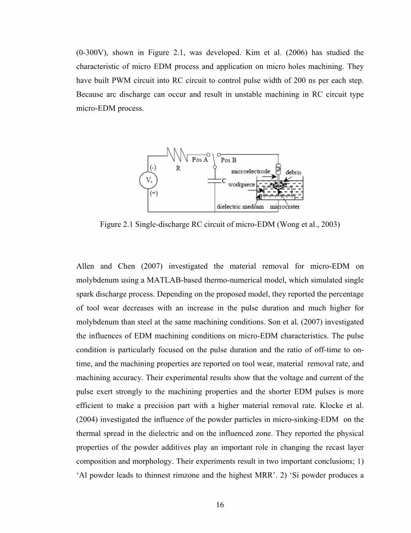
(0-300V), shown in Figure 2.1, was developed. Kim et al. (2006) has studied the
characteristic of micro EDM process and application on micro holes machining. They
have built PWM circuit into RC circuit to control pulse width of 200 ns per each step.
Because arc discharge can occur and result in unstable machining in RC circuit type
micro-EDM process.
Figure 2.1 Single-discharge RC circuit of micro-EDM (Wong et al., 2003)
Allen and Chen (2007) investigated the material removal for micro-EDM on
molybdenum using a MATLAB-based thermo-numerical model, which simulated single
spark discharge process. Depending on the proposed model, they reported the percentage
of tool wear decreases with an increase in the pulse duration and much higher for
molybdenum than steel at the same machining conditions. Son et al. (2007) investigated
the influences of EDM machining conditions on micro-EDM characteristics. The pulse
condition is particularly focused on the pulse duration and the ratio of off-time to on-
time, and the machining properties are reported on tool wear, material removal rate, and
machining accuracy. Their experimental results show that the voltage and current of the
pulse exert strongly to the machining properties and the shorter EDM pulses is more
efficient to make a precision part with a higher material removal rate. Klocke et al.
(2004) investigated the influence of the powder particles in micro-sinking-EDM on the
thermal spread in the dielectric and on the influenced zone. They reported the physical
properties of the powder additives play an important role in changing the recast layer
composition and morphology. Their experiments result in two important conclusions; 1)
‘Al powder leads to thinnest rimzone and the highest MRR’. 2) ‘Si powder produces a
16
grey zone beneath the actual “white zone” ’. Liu et al. (2005) reported that material
removal rate (MRR) for micro-hole machining over high nickel alloys is increasing
sharply with increasing discharge current, and reached a maximum at a discharge current
of 500 mA when pulse duration is fixed at 4 µs. This report reveals that a significant
portion of the total energy is used to vaporize the material at lower current result in
reducing in MRR, however, when the discharge current is too large (e.g. 2A) the
explosive energy density is huge, and the discharge spark is drastic.
In addition, type of dielectrics fluid used during machining is also effective factor for
material removal rate in micro-EDM. MRR was found to be higher when pure water was
used as a dielectric liquid compared to the keresone use was lower (Lin et al, 2007).
Tool wear is found to be very small when the deionized water is used in working
medium, machining time also decreases due to a fast machining federate (Chung et al,
2007)
2.3 Tool Electrode Manufacturing and Wear in Micro-EDM
Micro-tool electrode manufacturing is going to be more important for micro parts and
holes machining in micro-EDM. With improving very small size tool manufacturing
technology, micro-EDM mostly beginning to use, especially, for micro-hole drilling.
The most powerful technique for manufacturing micro-tool is WEDG (Wire Electro-
Discharge Grinding), shown in Figure 2.2, proposed firstly by Masuzawa et al. (1985). It
is an important step of the improving technology in micro-EDM.
In addition to WEDG process, some other techniques also proposed by the researchers,
Yamazaki et al. (2004) proposed a method to produce micro-rod electrode using
machined holes as shown in Figure 2.3. With the proposed model, a straight rod can be
formed with an electric capacitance of 10-220 pF and feed speed of 2 µm at a machining
time of 5 min; any rod electrode diameter can be obtained by off-centering, complicated
shapes such as asymmetrical, stepped and multi-rods can be formed.
17

Figure 2.2 Principle of WEDG with one wire guide (Fleischer, 2004)
Figure 2.3 Principle of obtaining micro-rods (Yamazaki et al., 2004)
Takahata et al. (1999) developed a novel micro-EDM method using electrodes
fabricated by the LIGA* process as shown in Figure 2.4. With this method, they can
achieve to produce high-aspect-ratio micro structure from various kinds of materials
with short machining times and to achieve high electrode wear resistance by employing
electroplated copper electrodes. Multiple structures can be produced in parallel by using
an electrode array. It is possible to convert micro-EDM process from serial to parallel
fabrication.
* LIGA is the abbreviation from the German words, “Lithographie”, “Galvanik”, and “Abformung” In LIGA process, a mold insert is made by deep lithography coupled with micro electroforming; mass production is then carried out by molding technique.
18
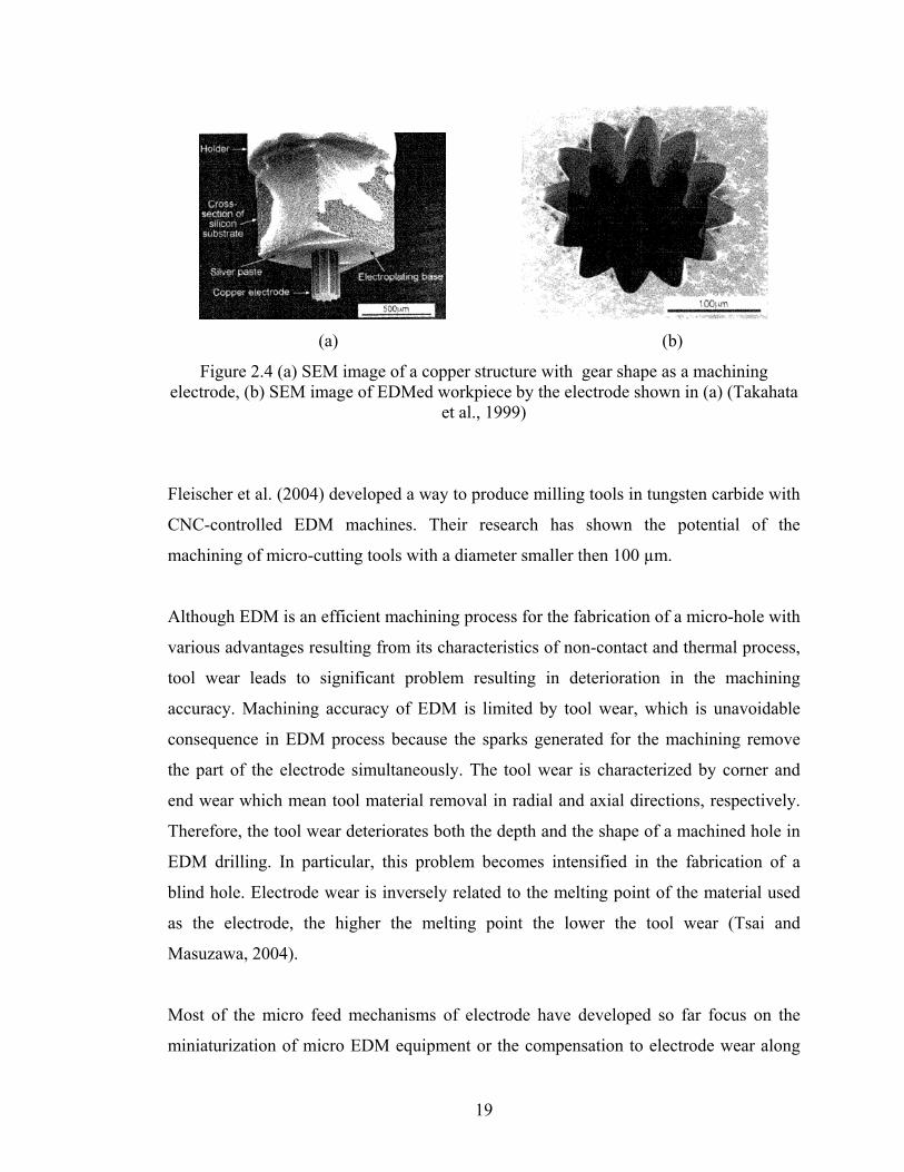
(a) (b)
Figure 2.4 (a) SEM image of a copper structure with gear shape as a machining electrode, (b) SEM image of EDMed workpiece by the electrode shown in (a) (Takahata
et al., 1999)
Fleischer et al. (2004) developed a way to produce milling tools in tungsten carbide with
CNC-controlled EDM machines. Their research has shown the potential of the
machining of micro-cutting tools with a diameter smaller then 100 µm.
Although EDM is an efficient machining process for the fabrication of a micro-hole with
various advantages resulting from its characteristics of non-contact and thermal process,
tool wear leads to significant problem resulting in deterioration in the machining
accuracy. Machining accuracy of EDM is limited by tool wear, which is unavoidable
consequence in EDM process because the sparks generated for the machining remove
the part of the electrode simultaneously. The tool wear is characterized by corner and
end wear which mean tool material removal in radial and axial directions, respectively.
Therefore, the tool wear deteriorates both the depth and the shape of a machined hole in
EDM drilling. In particular, this problem becomes intensified in the fabrication of a
blind hole. Electrode wear is inversely related to the melting point of the material used
as the electrode, the higher the melting point the lower the tool wear (Tsai and
Masuzawa, 2004).
Most of the micro feed mechanisms of electrode have developed so far focus on the
miniaturization of micro EDM equipment or the compensation to electrode wear along
19

feed direction. Introducing vibration and rotation onto electrode in feeding is certainly
beneficial to keep stable and efficient machining process. In micro hole drilling, the
wear of electrode is relatively significant. The fore end shape of electrode is difficult to
be kept due to the radial wear of electrode directly affecting it, though the axial loss can
be compensated (Li et al. 2002).
Yu et al. (1998) proposed a method based on layer-by-layer machining with maintaining
the original tool shape, which is called Uniform Wear Method. This method is very
useful for micro electrical discharge milling process; complex shape of cavity can be
machined with a nearly designed aspect ratio, it provides to enable wear compensation.
They stated that if a small depth of cut was used and a tool path was chosen that crossed
over the previous path by the radius of the tool, the majority of the wear would occur
from the end of the tool. If the tool path is long, the tool will be significantly shorter at
the end of the path; therefore the next is reversed in order to achieve a flat substructure.
Pham et al. (2007) investigated the electrode wear during micro-electrical discharge
drilling with micro rod and micro tube electrodes, shown in Figure 2.5. They reported
that wear measurement increasing dramatically after a certain depth while rod electrode
is used. This is mainly expected due to deteriorated flushing conditions. Good flushing
should be enabled to avoid from side sparking on the electrode. However, tubular
electrode is more stabilize in deep depth when comparing to the rod electrode.
Figure 2.5 (a) Shape of micro-hole by tubular electrode (b) shape of micro-hole by rod
electrode (Pham et al., 2007)
20
Tsai and Masuzawa (2004) investigated the relationship between the tool wear ratio and
the thermal properties of tool and workpiece made of a variety of materials. And they
proposed a repetitive machining method which uses reground tools until a required
profile is obtained.
2.4 2D&3D Machining by micro-EDM
EDM process is a mostly favored machining technique to produce microstructures and
micro mold with 3 dimensions (3D) and high aspect ratios. Feasibility of micro tool
electrode by WEDG unit in micro EDM systems also gains advantages in 3D micro
parts manufacturing. This type of EDM process generally called as electrical discharge
milling process, because the tool electrode has a movement through the defined tool path
like in milling operation. A CAD/CAM system is also needed to generate tool path for
the electrode.
Recently published papers about micro-mold machining by using micro-EDM process
are cited with their remarkable points. Electrode wear is again a drawback for 3D
machining, it is necessary to compensate the worn length of the electrode. Zhao et al.
(2004) have used online measurement of electrode wear to compensate the electrode
wear and maintain the machining accuracy. Rajurkar and Yu proposed (2000) an
approach to integrate CAD/CAM systems with micro-EDM while accounting for tool
wear using recently developed uniform wear method. Using this proposed approach,
some complex 3D micro shapes were machined successfully. Lim et al. (2003) have
studied the machining of high aspect ratio micro-structures using micro-EDM.
Paremeters affecting the micro-EDM were investigated and micro-structure has been
successively fabricated. They realized that the machining dept is inversely proportional
to the feed rate. A micro slit die easily manufactured using a micro electrical discharge
machining (micro-EDM) is proposed for micro heat sink fabrication (Wang et al. 2005).
Fabrication of biocompatible microdevices has been studied by using the micro electro
discharge machining (Murali and Yeo, 2004). Micro channels with feature size of 25 μm
can be produced. The process is made more effective by introducing ultrasonic vibration
21

of the workpiece. The total time needed for fabricating these microdevices by micro-
EDM is comparatively shorter than that of machining by lithographic and etching
techniques. Cao et al. (2007) reported the fabrication of microscale Ta† mold by using
micro-EDM. Surface morphology of the micro-EDMed Ta molds are characterized by
scanning electron microscope, X-ray photoelectron spectroscopy, and transmission
electron microscopy. Han et al. (2006) investigated the manufacturing of the smallest
possible rod diameter obtained by micro-EDM. Based on their investigation results, sub-
micrometer machining using SWC (Cemented tungsten carbide made of super fine
particles) was attempted, and the smallest possible diameter obtained was about 2.8 µm.
Takahata and Gianchandani (2002) proposed a micro-electro-discharge machining
techniques that uses electrode arrays fabricated by LIGA process to achieve high
parellesizm and throughput in the machining. According to the their techniques, Using
electrode arrays with four circuits, batch production of 36 WC-Co gears with 300 µm
outside diameter and 70 µm thickness in 15 min are produced as shown in Figure 2.6.
The results obtained clearly revealed that using arrayed electrodes with separate pulse
control circuits (RC pairs) for each array partition can vastly increase the machining
rate.
Tseng et al. (2005) reported the integration of LIGA and micro-EDM to fabricate the
micro mold for the ink jet printer nozzle plates. With this method, the positioning an
alignment accuracy of the micro pins and holes have improved significantly. Li and
Senturia (1992) reported the use of micro-EDM to fabricate molding tools with which
plastic parts are molded having dimensions on the order of tens of microns.
† Ta is the abbreiviation of Tantalum element.
22

(a)
(b)
Figure 2.6 (a) Cu electrode arrays with patterned interconnect fabricated by using LIGA technique with two-mask alignment sequence, (b) WC-Co super hard alloy gears cut
from a 70-µm-thick workpiece using electrode arrays of (a) (Takahata and Gianchandani, 2002)
2.5 Micro hole Machining by Varying micro-EDM Specifications
Micro-EDM is one of the most powerful methods for drilling micro-holes in any
electrically conductive materials, since circular rod electrode with a very small diameter
of 5 μm can be fabricated by using WEDG unit placed on the micro-EDM machine
(Masuzawa, 1997). The depth of the holes which can be drilled will be rather limited,
since the side gap between electrode and workpiece is very narrow in micro-EDM. This
is an obstacle to remove away debris from sparking area, and result in bad discharge
called arc and short circuit. Recent study in micro-EDM is generally condensed to get
high aspect ratio in micro-holes, inner and exit diameter differences, surface and
geometrical shape quality, and minimum achievable size in micro-hole manufacturing.
23
A literature survey on micro-hole machining by using micro-EDM with different
decisive specifications is presented below.
Masuzawa et al. (1989) proposed a horizontal EDM system for drilling deep, small
holes. They can manage to machine deep, small hole with an aspect ratio around 10 and
they can produce Ø 55 μm hole with a depth of 500 μm within 30 seconds. Her et al.
(2001) have studied on micro-hole machining of copper with traditional EDM machine
using a tungsten carbide tool electrode. They reported that electrode wear and hole
enlargement are both smaller, and a better profile of micro hole can be obtained when
positive polarity machining is selected, however, electrode wear is higher when positive
polarity machining is selected. In addition, the author also emphasized that material
removal rate is higher when negative polarity machining and tungsten carbide electrode
are selected.
In micro hole drilling, the fore end shape of electrode can not be kept stable because of
the radial wear of electrode, although the axial loss can be compensated. The wear on
fore-end of tool electrode alters the precision and shape of holes. In case of through hole
drilling, feeding over the tool electrode gain significance so that the exit diameter of the
hole is enlarged and going to be equal to the entry one (Li et al, 2002). The technique
shaping the circular rod electrode with circular crosssection into the semi-circular or non
circular crosssection become very efficient for machining micro-hole with high aspect
ratio. The tool electrode is shaped by cutting1/5 to 1/4 of the diameter off from two sides
using WEDG unit (Masuzawa et al, 1989). Kim et al. (2006) proposed a method to
reduce the difference between the entrance and exit diameters of the hole. By reducing
secondary discharge, electrode wear, and capacitance when the tool was closed to the
exit of the hole by introducing ultrasonic vibration to the EDM, a mostly straight hole
was fabricated and inner shape of hole was not influenced from the proposed method.
Yan et al. (2002) have studied on the precise micro hole machining with a high aspect
ratios in borosilicate glass. They used a machining method which combines micro-EDM
and micro ultrasonic vibration machining (MUSM). Their experimental results show that
using appropriate machining parameters; the diameter variations between the entrances
24

and exits (DVEE) can be decreased to nearly 2 µm in micro holes with a diameter of 150
µm and depths of 500 µm. In that paper, authors claimed that DVEE can be enhanced by
improving an ultrasonic amplitude or rotational speed and also they reported the degree
of micro-hole roundness mostly related to the machining tool rotation speed.
Li et al. (2002) proposed that an inchworm type micro feeding mechanism in micro-
EDM. With the aid of this mechanism, micro holes and micro-rods with an aspect ratio
of more than 20 and 10 obtained respectively. Wansheng et al. (2002) introduced the
ultrasonic vibration into micro-EDM when they made their experiments with a single
side notched cylindrical tool electrode, shown in Figure 2.7. They reported that holes
with a diameter of less than Ø0.2 mm and aspect ratio of more than 15 can be machined
steadily using this technology.
Figure 2.7 Section view of a single-notch electrode (Wansheng et al., 2002)
Yeo et al. (2004) investigated the feasibility of a magnetic field to obtain higher aspect
holes on hardened tool steel using micro-EDM process. They reported that the magnetic
field can assist to improve debris circulation, and they achieve to machine a hole with a
depth of 1177 µm in 360 min, which is 26% higher than that of achieved in conventional
micro-EDM. Hung et al. (2006) have used a helical micro-tool electrode to drill and
finish micro-holes by using micro-electro-discharge machining combined with
ultrasonic vibration. They reported that this method can substantially reduce the EDM
gap, taper and machining time for deep micro hole drilling. Moreover, using a helical
micro-tool with micro ultrasonic vibration finishing, good surface quality and less taper
25
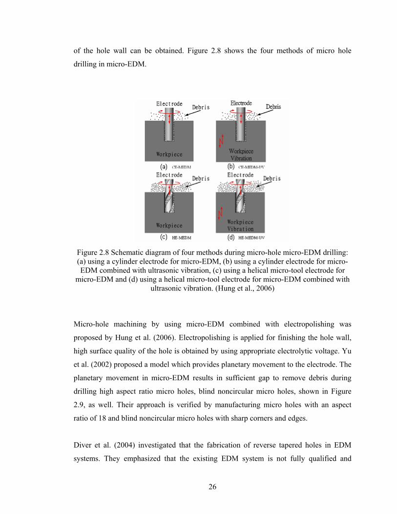
of the hole wall can be obtained. Figure 2.8 shows the four methods of micro hole
drilling in micro-EDM.
Figure 2.8 Schematic diagram of four methods during micro-hole micro-EDM drilling: (a) using a cylinder electrode for micro-EDM, (b) using a cylinder electrode for micro-EDM combined with ultrasonic vibration, (c) using a helical micro-tool electrode for
micro-EDM and (d) using a helical micro-tool electrode for micro-EDM combined with ultrasonic vibration. (Hung et al., 2006)
Micro-hole machining by using micro-EDM combined with electropolishing was
proposed by Hung et al. (2006). Electropolishing is applied for finishing the hole wall,
high surface quality of the hole is obtained by using appropriate electrolytic voltage. Yu
et al. (2002) proposed a model which provides planetary movement to the electrode. The
planetary movement in micro-EDM results in sufficient gap to remove debris during
drilling high aspect ratio micro holes, blind noncircular micro holes, shown in Figure
2.9, as well. Their approach is verified by manufacturing micro holes with an aspect
ratio of 18 and blind noncircular micro holes with sharp corners and edges.
Diver et al. (2004) investigated that the fabrication of reverse tapered holes in EDM
systems. They emphasized that the existing EDM system is not fully qualified and
26

produce low quality reverse tapered holes. According to their novel technique, tapered
holes with a entry diameter of 100 µm and exit diameter of 160 µm can be produced.
The other alternative ways of producing tapered holes are listed below (Diver et al.,
2004);
(a) “Modify the EDM parameters (e.g. voltage, frequency, current, gap ,gain, or
pulse width) during machining to remove more material radially as the dept of
machining increases.
(b) Move the workpiece relative to the electrode to achieve the desired hole taper.
(c) Change the electrode angle and position radially during drilling.
(d) Feed and rotate the electrode at the angle required to achieve the desired hole
taper.”
(a) (b) (c) Figure 2.9 (a) triangular blind hole (b) square blind hole (c) pentagonal blind hole (Yu et
al., 2002)
Weng (2006) investigated the manufacturing of microparts with an array of micro holes
using the machined micrographite –copper electrode in EDM. This electrode is
fabricated by using electrochemical process of anodic etching combined with
electroforming process. He indicated that yielding parts can be utilized as a microwater
spray nozzle in the biotechnology applications. Nakaoku et al. (2007) investigated that
the basic characteristic of micro-EDM by machining micro holes in sintered diamond.
They reported that micro-holes with a diameter of 50 µm can be machined in sintered
diamond and machining characteristic is similar to the tungsten carbide alloy. In
addition, they observed that side gap between electrode and hole wall increases with
increasing open-circuit voltage. Kaminski and Capuano (2003) reported that the
27

28
parameters affecting the micro holes machining process when diameter smaller than 0.1
mm and aspect ratio bigger than 20 by electro-erosion penetration process in sheets. And
circularity deviation provided by the experiment was smaller than 0.01 for 0.1 mm
diameter holes.
CHAPTER 3
EXPERIMENTAL SETUPS AND PROCEDURES
In this chapter, experimental set-up and tools are described by giving their specifications
and functions. Throughout the chapter, experimental procedures explained with all
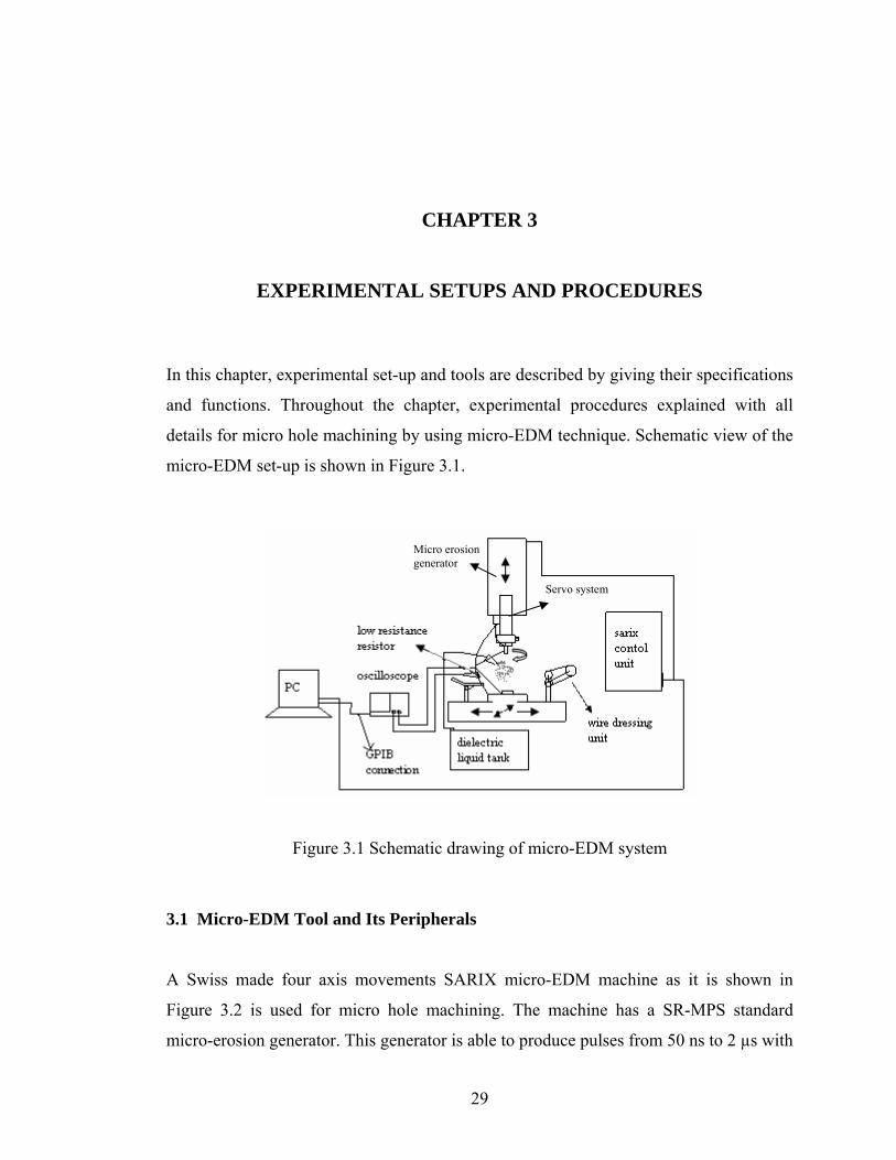
details for micro hole machining by using micro-EDM technique. Schematic view of the
micro-EDM set-up is shown in Figure 3.1.
Micro erosion generator
Servo system
Figure 3.1 Schematic drawing of micro-EDM system
3.1 Micro-EDM Tool and Its Peripherals
A Swiss made four axis movements SARIX micro-EDM machine as it is shown in
Figure 3.2 is used for micro hole machining. The machine has a SR-MPS standard
micro-erosion generator. This generator is able to produce pulses from 50 ns to 2 µs with
29

electrical current peak values up to 50 A. Power supply can vary voltage levels from 50
V to 250 V, but this is limited up to 100 V for the used micro-EDM machine. In addition
to the micro erosion generator, the micro-EDM machine is also composed of the
following parts; SX-CU control unit, SX-MMI panel and SX-DA unit. SX-CU includes
the electrical circuits and control mechanisms which run the machine. SX-MMI panel is
the user’s command panel, the machine operator can control the machining parameters
and receive machining information on TFT color screen. SX-DA unit is the dielectric
liquid tank that has water-cooling system and filters the used dielectric liquid for
reusing.
Wire dressing unit (Figure 3.3) is integrated to micro-EDM machine to produce small
size tool electrode. It is used to reduce standard diameter of 400 µm electrode size to the
desired very small size of electrode. Micro-measurement system is installed to the wire
dressing unit to measure the electrode diameter whether within the expected range. To
measure the exact reduced diameter of the tool electrode, an optical microscope (Figure
3.3) with 125x magnification, installed on the work-table, is used. A CAD/CAM system
is used for 2D and 3D machining, Catia V5 is used for solid model of desired shapes and
Esprit CAM with EDM module is used to generate G-code for milling operation. Figure
3.4 illustrates the spark observation during machining and Figure 3.5 depicts the picture
of electrode dressing by wire dressing unit.
By using SX-MMI panel, electrical and technological parameters are set then drilling
operation is performed. A sample of micro-hole drilled with a Ø100 µm tool electrode
on the plastic mold steel plate is shown in Figure 3.6.
Micro-manufacturing process by micro-EDM and consequent processes such as
measurement and sectioning process are depicted by using flowchart as shown in Figure
3.7. All the mentioned experimental process in the flowchart is explained in details in
the forthcoming sections.
30

SR-MPS Generator
SX-CU
SX-MMI
SX-DA
Figure 3.2 Micro-EDM machine
Wire dressing unit
Resistor connection
Optical microscope
Figure 3.3 Wire dressing unit, Optical microscope with 125x magnification
31

spark
Figure 3.4 Spark observation during machining
Figure 3.5 Electrode dressing by wire dressing unit
32
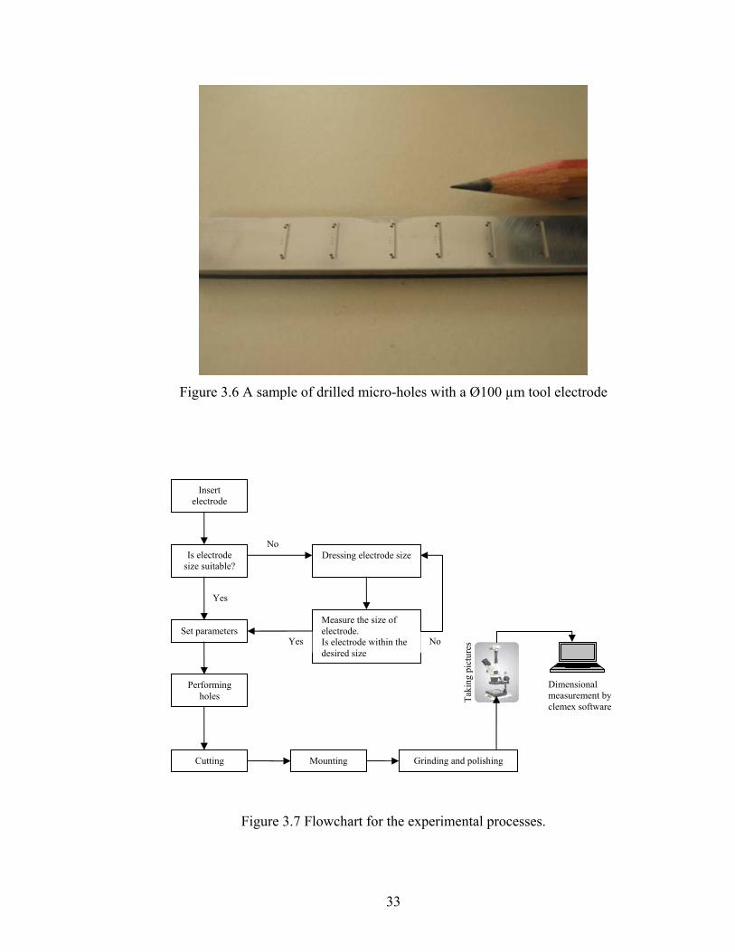
Figure 3.6 A sample of drilled micro-holes with a Ø100 µm tool electrode
Insert electrode
Figure 3.7 Flowchart for the experimental processes.
Is electrode size suitable?
Set parameters
Performing holes
Dressing electrode size
Measure the size of electrode. Is electrode within the desired size
No
Cutting Mounting Grinding and polishing
Yes
Yes No
Taki
ng p
ictu
res
Dimensional measurement by clemex software
33

3.2 Material Used for Micro-Hole Machining Plastic mold steel (70x10x2) as illustrated in Figure 3.8 is used as a wokpiece material.
Tungsten carbide (WC) electrodes (Figure 3.9) with a standard diameter of 400 µm and
100 µm are used as a tool electrode. Stiffness and rigidity of tungsten carbide is very
high when comparing to tool steel. This is because tungsten carbide electrode size can be
reduced to very small size and prevents bending or swinging during machining. Wear
resistance of tungsten carbide is also better than that of tool steel. This provides
advantages for micro-hole drilling since less deterioration occur in the shape of target
holes. The properties of WC is given in Table 3.1.Dielectric liquid used for flushing is a
hydro carbide composed of mineral and synthetic oils. Its characteristics are tabulated in
Table 3.2.
Figure 3.8 Sample of plastic mold steel (70x10x2) used for micro-EDM
Ø400 µm
Ø100 µm
MP725 0.2 ohm 1%R Resistor
Figure 3.9 Tool electrodes and low resistance resistor
34

Table 3.1 Tungsten Carbide (WC) Properties:
(http://en.wikipedia.org/wiki/Tungsten_carbide)
Density and phase : 15.8 g·cm−3, solid
Solubility in water : Insoluble
Melting point : 2870 °C
Boiling point : 6000°C
Thermal conductivity : 84.02 W·m−1·K−1
Tensile strength : 0.3448 GPa
Mohs hardness : 9
Table 3.2 Dielectric Oil Characteristics:
Dielectric Oil labeled as HEDMA111 supplied from Sarix company.
Viscosity 20 °C : 2,4 cSt
Density 15 °C : 0,781 Kg/l
Point of flammability : 101 °C
Original smell : neutral
3.3 Receiving Voltage and Current Pulse Shapes
Capturing voltage and current pulse forms in micro-EDM is very essential since by
means of the pulse forms generated during machining many parameters value and type
which are decisive in machining qualities are found such as current, pulse-on/off, and
discharge type such as arc, and short circuits. Low inductance 0.2 ohm 1%R MP725
resistor (Figure 3.9) is connected to discharge circuit as shown in Figure 3.1 and Figure
3.3. By using this resistor current value during electrical discharge will be discovered.
An Agilent 54621D mixed signal oscilloscope with a value of 60MHz and 200 MSa/sec
as shown in Figure 3.10 is used to display the shape of voltage and current pulse forms
and also their numerical values. A connection will be installed between oscilloscope and
computer by using Agilent GPIB connection card to transfer the oscilloscope data into
35

the computer environment. An Agilent sample Excel data acquisition macro program is
used to get a number of voltage data from the captured pulse forms.
Figure 3.10 Agilent 54621D Mixed Signal Oscilloscope 60MHz/ 200Msa/sec
3.4 Taking Cross-Section of Micro-Holes
An attempt is made to observe the cross-sectional view of machined holes by using
micro-EDM. This is a very beneficial work to have a knowledge about the hole shape
geometry along the holes tubular section. We realized its importance especially when the
cross-sectional view of the machined holes are taken accurately since considerably
important defects are observed on the shape of hole geometry. The procedures for taking
cross-section of machined holes are stated explicitly in following section.
The plastic mold steel plate is cut to the smaller specimen parts to observe the shape of
the geometry of micro holes cross-section. Buehler precision isomet low speed saw as
shown in Figure 3.11, settled in Zonguldak Karaelmas University is used to cut the
specimen from the steel plate. It has a blade disc with a thickness of 0.4 mm that enables
to cut the material with a little or no deformation. The blade disc is placed on the steel
36

plate where the blade disc almost tangential to the hole circumference then at this point
plate will be cut and turns into the small specimen including generally three holes.
After cutting the specimen, the coming process is mounting. The aim of the mounting
process is to handle the small and odd shaped specimens for next grinding and polishing
process. For this purpose, an automatic hot mounting press (Metapress-A) as shown in
Figure 3.12 is purchased from Metkon Instruments Ltd.
After mounting the specimen, the next process is the grinding and polishing. The aim of
this process is to obtain highly reflective surface which is free from scratches and
deformations. FORCIPOL-1 grinding and polishing machine together with FORCIMAT
automatic head as shown in Figure 3.13, settled in Zonguldak Karaelmas University, is
used to get a good surface for microscopic analysis. Afterwards applying the all the
processes mentioned above, the specimen (Figure 3.14) will be ready for the hole cross-
section shape observation by using microscopes. An overall picture of used
metallographic machines is shown in Figure 3.15.
Figure 3.11 Buehler precision isomet low speed saw
37
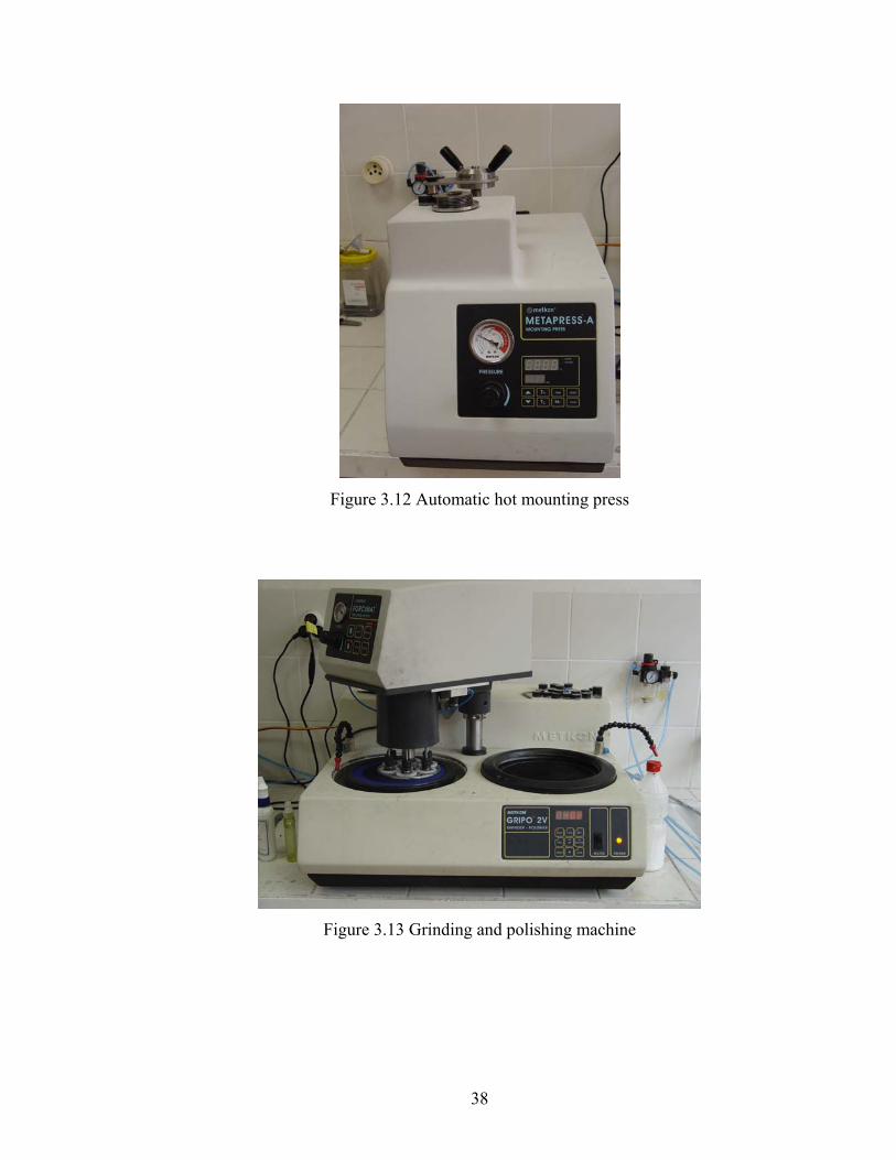
Figure 3.12 Automatic hot mounting press
Figure 3.13 Grinding and polishing machine
38

Figure 3.14 A sample of specimen
Figure 3.15 Overall picture of metallographic machines used in specimen preparation
39

3.5 Use of Microscope and Dimensional Measurement
Machined micro-holes and their cross-sectioned geometry are examined by using Nikon
ECLIPSE LV150 optical microscope (Figure 3.16). It has five objectives with a
magnification of 50x, 100x, 200x, 500x, 1000x. A ‘Nikon digital camera coolpix 8400’
(Figure 3.16) installed on the top of microscope is also used to take the pictures of cross-
sectional view of micro-holes. The hole pictures taken by camera is sent to the computer
and by means of the Clemex image analysis software dimensional measurement will be
done.
Digital camera
Figure 3.16 Nikon microscope and digital camera
Nikon Digital Camera
40

CHAPTER 4
EXPERIMENTAL RESULTS AND DISCUSSIONS
In this chapter, experimental results of machined micro-holes will be presented. Some
electrical and technological parameters such as current, energy, pulse width, and
frequency which are undisclosed in Sarix micro-EDM machine will be defined and their
influences on machined surface will be explained depending on experimental results.
Formation of micro-holes geometry under different machining conditions is observed.
Technological parameters which play an important role in determination of micro-hole
geometry are investigated experimentally. Through holes and mostly blind holes are
machined within the context of thesis. In through hole drilling, entrance and exit
diameter variations are examined, in blind hole drilling, entrance diameter and fore end
of holes are examined and the way is recommended to provide the parallelism in hole
wall-side. The cross-sectional views of the holes demonstrate how the defects are
formed inside the hole and they are not observed without taking cross-sectioned view.
Preventive and predictive technological techniques for minimizing defects formation in
hole geometry are also explained.
Achievable aspect ratios of holes under the specified machining conditions will be
investigated and presented. In addition, material removal rate and tool electrode wear
rate will be investigated and explained with the experimental facts. Based on the
experimental results and machine technology, repeatability and accuracy of machined
parts will be discussed. Throughout the experiments workpiece material, tool electrode
material and dielectric liquid remain same to enable identical experimental conditions.
41

4.1 Hole Machining Considering Energy Parameter
A series of experiments were performed to estimate the undisclosed parameters defined
in the micro-EDM machine. Those parameters only entered as a setting without a unit,
which are energy and current. Although discharge energy depends on voltage and
current disregarding less significant parameters, it is given in the machine settings as a
type of pulse shapes and it enables to the machine discharge energy limitation. The
current defined in the machine settings also carry the approximate meaning like in the
energy.
To observe the influences of energy parameter in micro-EDM, a series of hole
machining were performed by keeping all parameters constant except energy. Machining
conditions are given in Table 4.1. Energy type will determine the shape of the discharge
pulse and it is classified into six different ranges. Description of energy levels is given in
Table 4.2.
In this part of the experiment, variations in hole geometry, material removal rate
(workpiece and electrode), hole depth, overcut in hole diameter are investigated. This
investigation reveal the effect of energy parameter on the hole machining. The voltage
and current in micro-hole machining is monitored and recorded. The monitoring
technique can assist in the selection and optimization of micro-hole EDM process
parameters.
Shape of the pulse forms with different energy parameters are given in Figure 4.1 to
Figure 4.6. Selection of lower value of energy parameter results in the lower value of
discharge time and discharge current. As it shown in Figure 4.1 peak current value
approximately rises to 20 A when the energy parameter set to 350, however, as it shown
in Figure 4.6 peak current decreases nearly to 5 A when the energy parameter set to 14.
Due to material removal relation to the discharge current, lower the current value results
in higher precision in material surface, so that short pulses can be selected for finishing
operation. However, long pulses should be selected for fast and rough machining
42
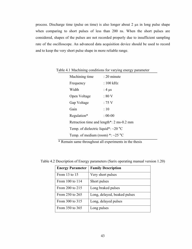
process. Discharge time (pulse on time) is also longer about 2 µs in long pulse shape
when comparing to short pulses of less than 200 ns. When the short pulses are
considered, shapes of the pulses are not recorded properly due to insufficient sampling
rate of the oscilloscope. An advanced data acquisition device should be used to record
and to keep the very short pulse shape in more reliable range.
Table 4.1 Machining conditions for varying energy parameter
Machining time : 20 minute
Frequency : 100 kHz
Width : 4 μs
Open Voltage : 80 V
Gap Voltage : 75 V
Gain : 10
Regulation* : 00-00
Retraction time and length*: 2 ms-0.2 mm
Temp. of dielectric liquid*: ~20 °C
Temp. of medium (room) *: ~25 °C
* Remain same throughout all experiments in the thesis
Table 4.2 Description of Energy parameters (Sarix operating manual version 1.20)
Energy Parameter Family Description
From 13 to 15 Very short pulses
From 100 to 114 Short pulses
From 200 to 215 Long braked pulses
From 250 to 265 Long, delayed, beaked pulses
From 300 to 315 Long, delayed pulses
From 350 to 365 Long pulses
43
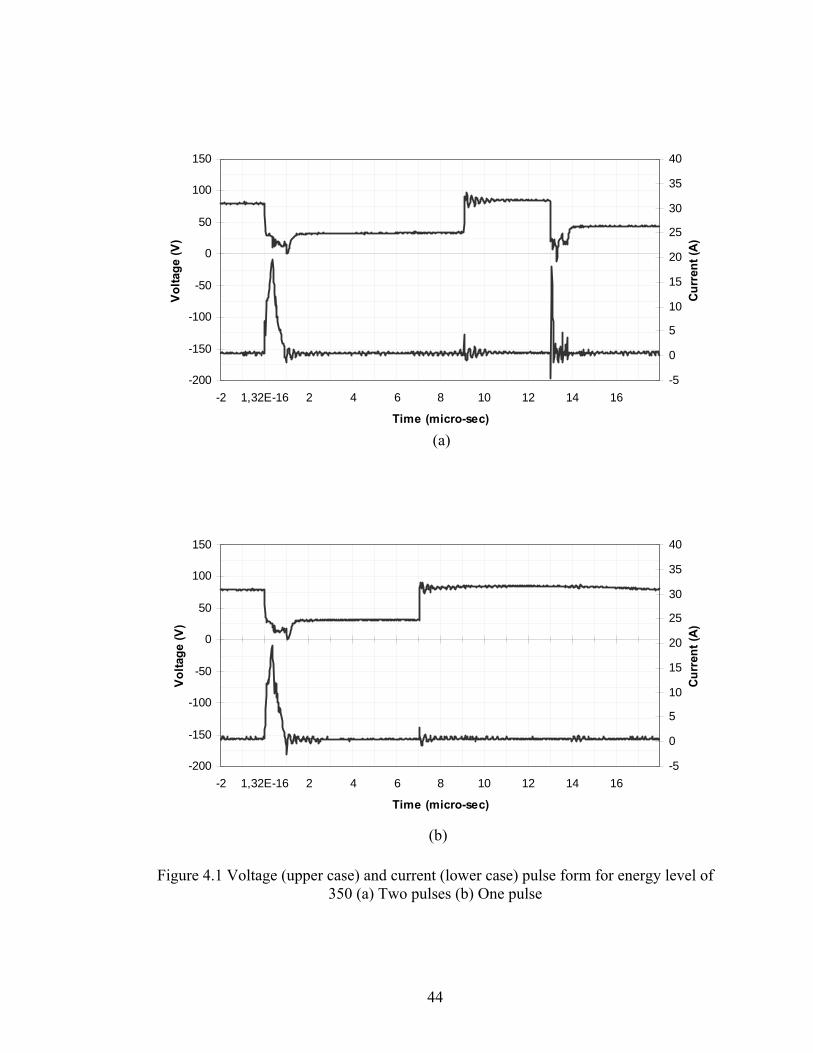
-200
-150
-100
-50
0
50
100
150
-2 1,32E-16 2 4 6 8 10 12 14 16
Time (micro-sec)
Vol
tage
(V)
-5
0
5
10
15
20
25
30
35
40
Curr
ent (
A)
(a)
-200
-150
-100
-50
0
50
100
150
-2 1,32E-16 2 4 6 8 10 12 14 16
Time (micro-sec)
Volta
ge (V
)
-5
0
5
10
15
20
25
30
35
40
Curr
ent (
A)
(b)
Figure 4.1 Voltage (upper case) and current (lower case) pulse form for energy level of 350 (a) Two pulses (b) One pulse
44
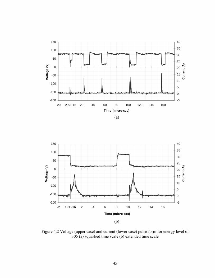
-200
-150
-100
-50
0
50
100
150
-20 -2,5E-15 20 40 60 80 100 120 140 160
Time (micro-sec)
Volta
ge (V
)
-5
0
5
10
15
20
25
30
35
40
Curr
ent (
A)
(a)
-200
-150
-100
-50
0
50
100
150
-2 1,3E-16 2 4 6 8 10 12 14 16
Time (micro-sec)
Volta
ge (V
)
-5
0
5
10
15
20
25
30
35
40
Curr
ent (
A)
(b)
Figure 4.2 Voltage (upper case) and current (lower case) pulse form for energy level of 305 (a) squashed time scale (b) extended time scale
45
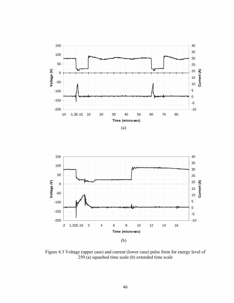
-200
-150
-100
-50
0
50
100
150
-10 -1,3E-15 10 20 30 40 50 60 70 80
Time (micro-sec)
Volta
ge (V
)
-10
-5
0
5
10
15
20
25
30
35
40
Curr
ent (
A)
(a)
-200
-150
-100
-50
0
50
100
150
-2 1,32E-16 2 4 6 8 10 12 14 16
Time (micro-sec)
Vol
tage
(V)
-10
-5
0
5
10
15
20
25
30
35
40
Curr
ent (
A)
(b)
Figure 4.3 Voltage (upper case) and current (lower case) pulse form for energy level of 250 (a) squashed time scale (b) extended time scale
46

-200
-150
-100
-50
0
50
100
150
-4,98 0,02 5,02 10,02 15,02 20,02 25,02 30,02 35,02 40,02
Time (micro-sec)
Vol
tage
(V)
-5
0
5
10
15
20
25
30
35
40
Curr
ent (
A)
(a)
-200
-150
-100
-50
0
50
100
150
-1,98 0,02 2,02 4,02 6,02 8,02 10,02 12,02 14,02 16,02
Time (micro-sec)
Volta
ge (v
)
-5
0
5
10
15
20
25
30
35
40
Curr
ent (
A)
(a)
Figure 4.4 Voltage (upper case) and current (lower case) pulse form for energy level of 205 (a) squashed time scale (b) extended time scale
47
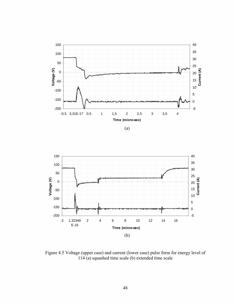
-200
-150
-100
-50
0
50
100
150
-0,5 3,31E-17 0,5 1 1,5 2 2,5 3 3,5 4
Time (micro-sec)
Volta
ge (V
)
-5
0
5
10
15
20
25
30
35
40
Curr
ent (
A)
(a)
-200
-150
-100
-50
0
50
100
150
-2 1,32349E-16
2 4 6 8 10 12 14 16
Time (micro-sec)
Vol
tage
(V)
-5
0
5
10
15
20
25
30
35
40
Cur
rent
(A)
(b)
Figure 4.5 Voltage (upper case) and current (lower case) pulse form for energy level of 114 (a) squashed time scale (b) extended time scale
48
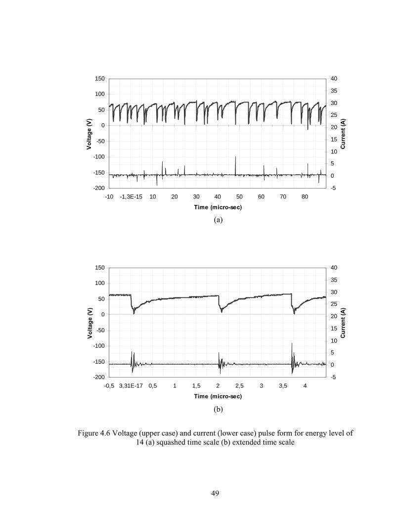
-200
-150
-100
-50
0
50
100
150
-10 -1,3E-15 10 20 30 40 50 60 70 80
Time (micro-sec)
Vol
tage
(V)
-5
0
5
10
15
20
25
30
35
40
Curr
ent (
A)
(a)
-200
-150
-100
-50
0
50
100
150
-0,5 3,31E-17 0,5 1 1,5 2 2,5 3 3,5 4
Time (micro-sec)
Vol
tage
(V)
-5
0
5
10
15
20
25
30
35
40
Curr
ent (
A)
(b)
Figure 4.6 Voltage (upper case) and current (lower case) pulse form for energy level of 14 (a) squashed time scale (b) extended time scale
49
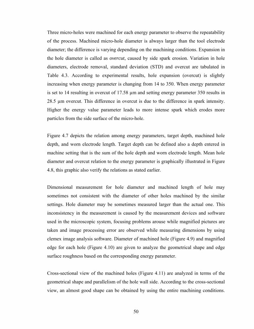
Three micro-holes were machined for each energy parameter to observe the repeatability
of the process. Machined micro-hole diameter is always larger than the tool electrode
diameter; the difference is varying depending on the machining conditions. Expansion in
the hole diameter is called as overcut, caused by side spark erosion. Variation in hole
diameters, electrode removal, standard deviation (STD) and overcut are tabulated in
Table 4.3. According to experimental results, hole expansion (overcut) is slightly
increasing when energy parameter is changing from 14 to 350. When energy parameter
is set to 14 resulting in overcut of 17.58 µm and setting energy parameter 350 results in
28.5 µm overcut. This difference in overcut is due to the difference in spark intensity.
Higher the energy value parameter leads to more intense spark which erodes more
particles from the side surface of the micro-hole.
Figure 4.7 depicts the relation among energy parameters, target depth, machined hole
depth, and worn electrode length. Target depth can be defined also a depth entered in
machine setting that is the sum of the hole depth and worn electrode length. Mean hole
diameter and overcut relation to the energy parameter is graphically illustrated in Figure
4.8, this graphic also verify the relations as stated earlier.
Dimensional measurement for hole diameter and machined length of hole may
sometimes not consistent with the diameter of other holes machined by the similar
settings. Hole diameter may be sometimes measured larger than the actual one. This
inconsistency in the measurement is caused by the measurement devices and software
used in the microscopic system, focusing problems arouse while magnified pictures are
taken and image processing error are observed while measuring dimensions by using
clemex image analysis software. Diameter of machined hole (Figure 4.9) and magnified
edge for each hole (Figure 4.10) are given to analyze the geometrical shape and edge
surface roughness based on the corresponding energy parameter.
Cross-sectional view of the machined holes (Figure 4.11) are analyzed in terms of the
geometrical shape and parallelism of the hole wall side. According to the cross-sectional
view, an almost good shape can be obtained by using the entire machining conditions.
50
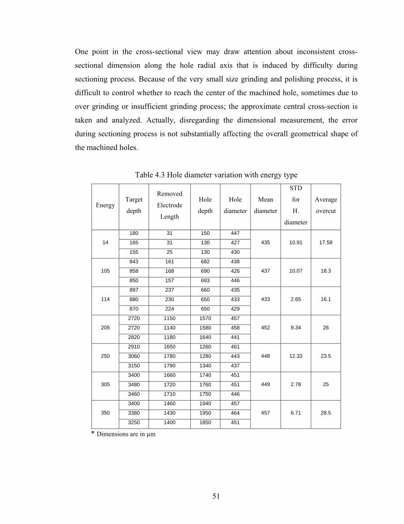
One point in the cross-sectional view may draw attention about inconsistent cross-
sectional dimension along the hole radial axis that is induced by difficulty during
sectioning process. Because of the very small size grinding and polishing process, it is
difficult to control whether to reach the center of the machined hole, sometimes due to
over grinding or insufficient grinding process; the approximate central cross-section is
taken and analyzed. Actually, disregarding the dimensional measurement, the error
during sectioning process is not substantially affecting the overall geometrical shape of
the machined holes.
Table 4.3 Hole diameter variation with energy type
Energy Target
depth
Removed
Electrode
Length
Hole
depth
Hole
diameter
Mean
diameter
STD
for
H.
diameter
Average
overcut
180 31 150 447
165 31 130 427 14
155 25 130 430
435 10.91 17.58
843 161 682 438
858 168 690 426 105
850 157 693 446
437 10.07 18.3
897 237 660 435
880 230 650 433 114
870 224 650 429
433 2.65 16.1
2720 1150 1570 457
2720 1140 1580 458 205
2820 1180 1640 441
452 9.34 26
2910 1650 1260 461
3060 1780 1280 443 250
3150 1790 1340 437
448 12.33 23.5
3400 1660 1740 451
3480 1720 1760 451 305
3460 1710 1750 446
449 2.78 25
3400 1460 1940 457
3380 1430 1950 464 350
3250 1400 1850 451
457 6.71 28.5
* Dimensions are in µm
51
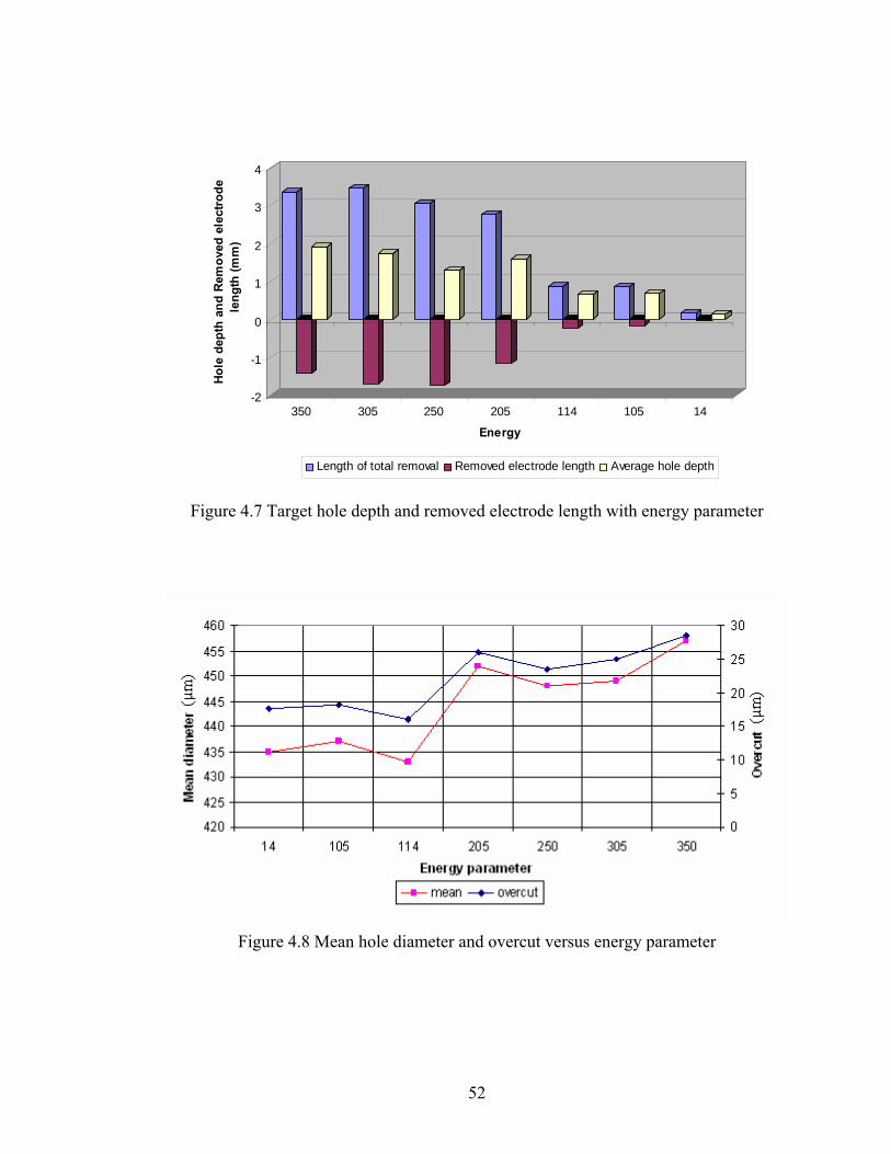
-2
-1
0
1
2
3
4
Hole
dep
th a
nd R
emov
ed e
lect
rode
le
ngth
(mm
)
350 305 250 205 114 105 14
Energy
Length of total removal Removed electrode length Average hole depth
Figure 4.7 Target hole depth and removed electrode length with energy parameter
Figure 4.8 Mean hole diameter and overcut versus energy parameter
52

a b c
d e f
Figure 4.9 Micro hole diameter measurement from top view, diameter measurement shown on the micro-hole photographs sequenced regarding with the energy level.
a b c
d e f
Figure 4.10 Micro-hole wall edge photographs with X1000 magnification with respect to energy level.
53
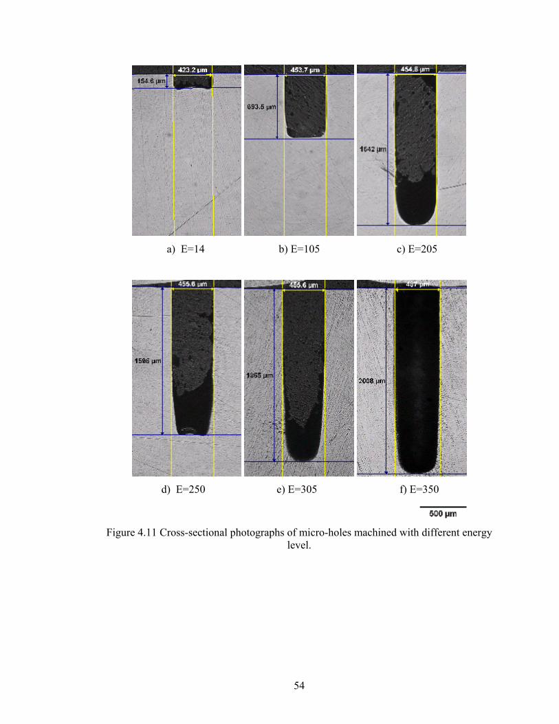
a) E=14 b) E=105 c) E=205
d) E=250 e) E=305 f) E=350
Figure 4.11 Cross-sectional photographs of micro-holes machined with different energy
level.
54

4.2 Hole Properties Versus Machining Time
These experiments are carried out to observe and understand the formation of micro hole
geometry under the constant micro-EDM parameters except machining time (Table 4.4).
Increasing the machining time gradually from 1 minute to 80 minutes enable us to
understand variation in hole geometry. It is understood that the variation in hole
geometry occur both in hole diameter, there is an expansion due to overcut caused by
side spark erosion, and in cross sectional geometry along the depth of hole. Towards the
bottom end of the holes, narrower section is formed because it is the mirrored shape of
the tool electrode. The end tip of the tool electrode is burned and gets the conic shape
which is caused by electric discharge intensity. Electric discharge intensity is higher at
the cornered and edge of the tool electrode. Because of this reason, the edge and corner
of the tool electrode is worn more than the side and smooth surface of the tool electrode.
Table 4.4 Machining parameters for varying machining time
Width : 4 μs
Frequency : 100 kHz
Currrent : 60
Voltage : 80 V
Gap voltage : 75 V
Gain : 10
Energy : 105
In this experiment, 42 holes are machined, each of them is machined for different time
duration which is increased gradually, to illustrate depth of holes and compare the
material and electrode removal rate. Total length including hole depth and electrode
removal is almost linearly increasing with the increasing machining time. The relation is
depicted in Figure 4.12.
55
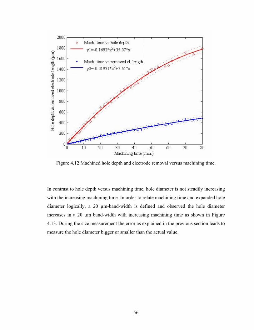
Figure 4.12 Machined hole depth and electrode removal versus machining time.
In contrast to hole depth versus machining time, hole diameter is not steadily increasing
with the increasing machining time. In order to relate machining time and expanded hole
diameter logically, a 20 µm-band-width is defined and observed the hole diameter
increases in a 20 µm band-width with increasing machining time as shown in Figure
4.13. During the size measurement the error as explained in the previous section leads to
measure the hole diameter bigger or smaller than the actual value.
56
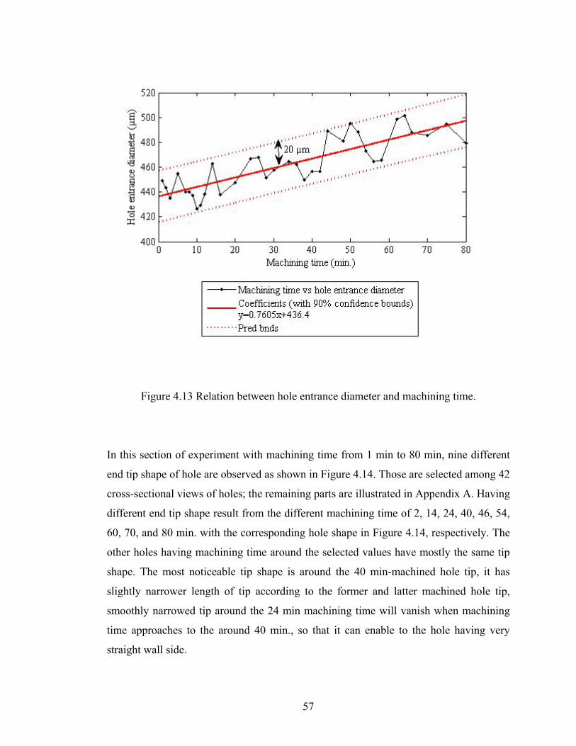
Figure 4.13 Relation between hole entrance diameter and machining time.
In this section of experiment with machining time from 1 min to 80 min, nine different
end tip shape of hole are observed as shown in Figure 4.14. Those are selected among 42
cross-sectional views of holes; the remaining parts are illustrated in Appendix A. Having
different end tip shape result from the different machining time of 2, 14, 24, 40, 46, 54,
60, 70, and 80 min. with the corresponding hole shape in Figure 4.14, respectively. The
other holes having machining time around the selected values have mostly the same tip
shape. The most noticeable tip shape is around the 40 min-machined hole tip, it has
slightly narrower length of tip according to the former and latter machined hole tip,
smoothly narrowed tip around the 24 min machining time will vanish when machining
time approaches to the around 40 min., so that it can enable to the hole having very
straight wall side.
57
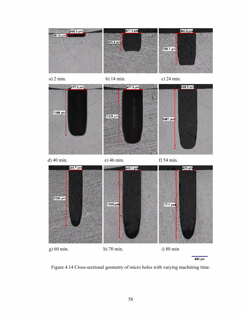
a) 2 min. b) 14 min. c) 24 min.
d) 40 min. e) 46 min. f) 54 min.
g) 60 min. h) 70 min. i) 80 min
Figure 4.14 Cross-sectional geometry of micro holes with varying machining time.
58

Actual hole depth and diameter are measured and analyzed by using commercially
available clemex image analyses software. A sample of measured picture for 24 min-
machined hole is depicted in Figure 4.15. In addition to the whole picture of machined
hole, the end tip shape for the specified hole is also illustrated in Figure 4.16 to
contribute the understanding of machining time effect on the hole tip formation easily.
Figure 4.15 A sample of geometrical shape analysis for 24min-machined hole.
14 min 24 min 40 min 46 min 54 min 60 min 70 min 80 min
Figure 4.16 End tip shape variation of hole with increasing machining time
59
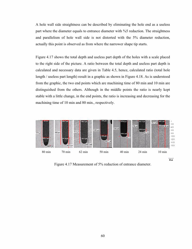
A hole wall side straightness can be described by eliminating the hole end as a useless
part where the diameter equals to entrance diameter with %5 reduction. The straightness
and parallelism of hole wall side is not distorted with the 5% diameter reduction,
actually this point is observed as from where the narrower shape tip starts.
Figure 4.17 shows the total depth and useless part depth of the holes with a scale placed
to the right side of the picture. A ratio between the total depth and useless part depth is
calculated and necessary data are given in Table 4.5, hence, calculated ratio (total hole
length / useless part length) result in a graphic as shown in Figure 4.18. As is understood
from the graphic, the two end points which are machining time of 80 min and 10 min are
distinguished from the others. Although in the middle points the ratio is nearly kept
stable with a little change, in the end points, the ratio is increasing and decreasing for the
machining time of 10 min and 80 min., respectively.
80 min 70 min 62 min 50 min 40 min 24 min 10 min
Figure 4.17 Measurement of 5% reduction of entrance diameter.
60
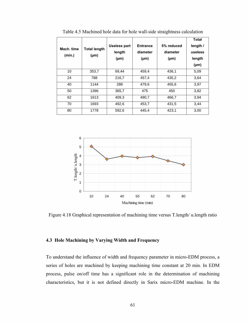
Table 4.5 Machined hole data for hole wall-side straightness calculation
Mach. time (min.)
Total length (µm)
Useless part length (µm)
Entrance diameter
(µm)
5% reduced diameter
(µm)
Total length / useless length (µm)
10 353,7 69,44 459,4 436,1 5,09
24 788 216,7 457,4 435,2 3,64
40 1144 288 479,6 455,6 3,97
50 1396 365,7 475 450 3,82
62 1613 409,3 490,7 466,7 3,94
70 1693 492,6 453,7 431,5 3,44
80 1778 592,6 445,4 423,1 3,00
0
1
2
3
4
5
6
10 24 40 50 62 70 80
Machining time (min)
T.le
ngth
/ u.le
ngth
Figure 4.18 Graphical representation of machining time versus T.length/ u.length ratio
4.3 Hole Machining by Varying Width and Frequency
To understand the influence of width and frequency parameter in micro-EDM process, a
series of holes are machined by keeping machining time constant at 20 min. In EDM
process, pulse on/off time has a significant role in the determination of machining
characteristics, but it is not defined directly in Sarix micro-EDM machine. In the
61
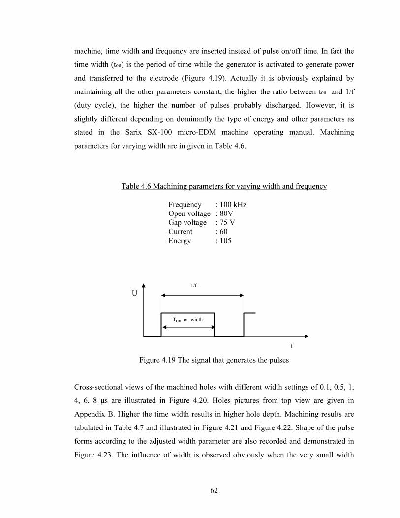
machine, time width and frequency are inserted instead of pulse on/off time. In fact the
time width (ton) is the period of time while the generator is activated to generate power
and transferred to the electrode (Figure 4.19). Actually it is obviously explained by
maintaining all the other parameters constant, the higher the ratio between ton and 1/f
(duty cycle), the higher the number of pulses probably discharged. However, it is
slightly different depending on dominantly the type of energy and other parameters as
stated in the Sarix SX-100 micro-EDM machine operating manual. Machining
parameters for varying width are in given in Table 4.6.
Table 4.6 Machining parameters for varying width and frequency
Frequency : 100 kHz Open voltage : 80V Gap voltage : 75 V Current : 60 Energy : 105
1/f U
Ton or width
t Figure 4.19 The signal that generates the pulses
Cross-sectional views of the machined holes with different width settings of 0.1, 0.5, 1,
4, 6, 8 μs are illustrated in Figure 4.20. Holes pictures from top view are given in
Appendix B. Higher the time width results in higher hole depth. Machining results are
tabulated in Table 4.7 and illustrated in Figure 4.21 and Figure 4.22. Shape of the pulse
forms according to the adjusted width parameter are also recorded and demonstrated in
Figure 4.23. The influence of width is observed obviously when the very small width
62

and large width differences are compared with each other, however, pulse shape
difference in very close width value is not observed easily but its effect can be seen
easily on the machined hole with increasing hole depth.
Another important parameter is the frequency value; actually it has inversely the same
effect on the machined part. Frequency value determine the period of time in which
include summation of the pulse power generator off and on time. It should be set
carefully to avoid from inconsistency during machining, frequency value must always
greater than the width time. Influence of the frequency is depicted by illustrating the
machined hole cross-sectional view with the different frequency values in Figure 4.24
and hole picture from top view are given in Appendix C.
a) Width: 0.1 μs b) Width: 0.5 μs c) Width: 1 μs
d) Width: 4 μs e) Width: 6 μs f) Width: 8 μs
Figure 4.20 Cross-sectional views of machined holes with variant width
63
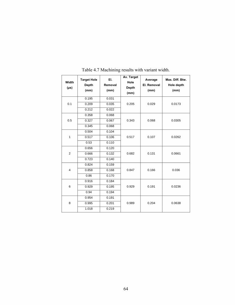
Table 4.7 Machining results with variant width.
Width (μs)
Target Hole Depth (mm)
El. Removal
(mm)
Av. Target Hole
Depth (mm)
Average El. Removal
(mm)
Max. Diff. Btw. Hole depth
(mm)
0.195 0.031
0.209 0.035 0.1
0.212 0.022
0.205 0.029 0.0173
0.358 0.068
0.327 0.067 0.5
0.345 0.068
0.343 0.068 0.0305
0.504 0.104
0.517 0.106 1
0.53 0.110
0.517 0.107 0.0262
0.656 0.120
0.666 0.132 2
0.723 0.140
0.682 0.131 0.0661
0.824 0.159
0.858 0.168 4
0.86 0.170
0.847 0.166 0.036
0.916 0.184
0.929 0.195 6
0.94 0.194
0.929 0.191 0.0236
0.954 0.191
0.995 0.201 8
1.018 0.219
0.989 0.204 0.0638
64

0
0,2
0,4
0,6
0,8
1
1,2
Width (micro-sec)
Ave
rage
Hol
e de
pth
& R
emov
ed E
lect
rode
Len
gth
(mm
)
Average hole depthAverage elecrode removal
Average hole depth 0,205 0,343 0,517 0,682 0,858 0,929 0,989
Average elecrode removal 0,094 0,068 0,107 0,131 0,168 0,191 0,204
0,1 0,5 1 2 4 6 8
Figure 4.21 Block diagram representation of average target hole depth and electrode
removal by variant width value.
Figure 4.22 Graphical representation of target hole depth versus width
65
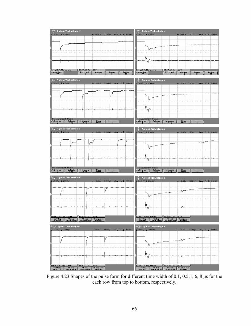
Figure 4.23 Shapes of the pulse form for different time width of 0.1, 0.5,1, 6, 8 μs for the
each row from top to bottom, respectively.
66
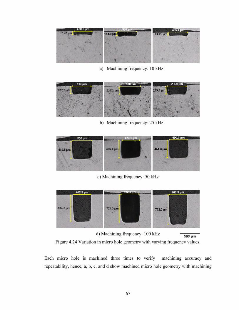
a) Machining frequency: 10 kHz
b) Machining frequency: 25 kHz
c) Machining frequency: 50 kHz
d) Machining frequency: 100 kHz
Figure 4.24 Variation in micro hole geometry with varying frequency values.
Each micro hole is machined three times to verify machining accuracy and
repeatability, hence, a, b, c, and d show machined micro hole geometry with machining
67

frequency of 10 kHz, 25 kHz, 50 kHz, and 100 kHz respectively. Machined holes
pictures from the top view are illustrated in Appendix B.
4.4 Hole Machining by Varying Open Voltage and Gap Voltage
Effects of open voltage and gap voltage on the shape of holes are investigated. In the
first case, gradually increasing open voltage by keeping gap voltage constant at 50 V
with machining time of 40 min. is used as an experimental condition. Holes machined
by setting open voltage at 55V, 60V, 70 V, 80V, and 90V are depicted in Figure 4.25,
respectively. Holes picture from top view and pulse shapes are also given in Appendix
D. The most remarkable point observed in the cross-sectional view of holes is the notch
formation at the end of the hole. The concluded remarks from the cross-sectional view of
the holes are stated below;
• Effect of gap voltage and open voltage is obvious, bottom end of the hole are
shaped as in the Figure 4.25 when the open voltage values as written in the
related pictures and gap voltage remain constant at 50 V.
• Depth of micro-hole is increasing with increasing open voltage.
• The inner fraction in the tip of micro hole is increasing gradually to 70 V after
this value this part is melt away.
As seen in Figure 4.25 the diameter of micro-holes are not consistent with the cross-
sectional view. The reason is that the diameter of micro hole is enlarged after very small
depth under micro-hole surface. But this depth is not seen in cross section view since
during the formation process of bakelite; it undergoes to high pressure then probably
vanishes.
68

a) 55 V b) 60 V c) 70 V
d) 80 V e) 90 V
Figure 4.25 Cross-sectional views of machined holes by using varying open voltages
In the second case of experiment, the effect of gap voltage in the geometry formation of
micro hole is investigated. By setting the gap voltage 95V, 90V, 80V, and 60V and
keeping open voltage constant at 100 V, micro-hole manufacturing is carried out and
variation in the geometry with machining different gap voltage is observed. When 95 V
and 90 V are used as gap voltage, the end of the micro-holes are more straight then the
other ones. When 80 V and 60 V are used as gap voltage the end tip of the micro-holes
turn into the different shape as shown in Figure 4.26. These results also verify the
statement declared as in the first case. The experiment for each voltage value is repeated
three times to show the reliability of experiments. In some of the machining, although
69

the fore end of the machined holes shape are consistent with each other, the hole depths
are sometimes are not preserved within the same level as shown in Figure 4.26. This
problem is considered to be arisen from the application of different machining time or
use of not sufficiently clear tool electrode that should be free from any carbon particles
for good discharge result.
1 2 3
Gap Voltage: 95 V
a b c
1 2 3
Gap voltage: 90 V
Figure 4.26 Cross-sectional views of machined holes by using variant gap voltage. Each
machining were repeated three times and represented by 1, 2, and 3.(cont)
70
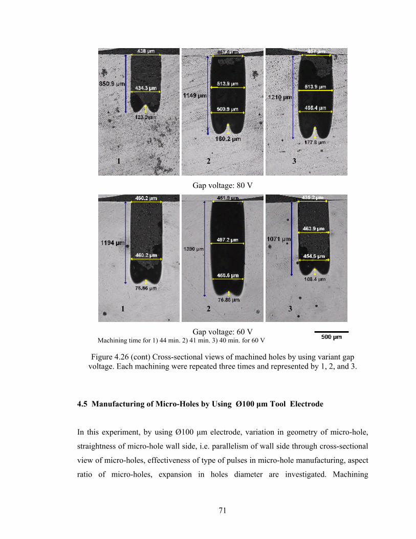
1 2 3
Gap voltage: 80 V
1 2 3
Gap voltage: 60 V Machining time for 1) 44 min. 2) 41 min. 3) 40 min. for 60 V
Figure 4.26 (cont) Cross-sectional views of machined holes by using variant gap voltage. Each machining were repeated three times and represented by 1, 2, and 3.
4.5 Manufacturing of Micro-Holes by Using Ø100 μm Tool Electrode
In this experiment, by using Ø100 μm electrode, variation in geometry of micro-hole,
straightness of micro-hole wall side, i.e. parallelism of wall side through cross-sectional
view of micro-holes, effectiveness of type of pulses in micro-hole manufacturing, aspect
ratio of micro-holes, expansion in holes diameter are investigated. Machining
71

parameters are given in Table 4.8. Cross-sectional views of machined micro-holes with
different machining time depicted in Figure 4.27. Concluded remarks are stated in the
coming sections.
Table 4.8 Machining parameters for hole machining by Ø100 μm electrode
Width : 5 μs Frequency : 100 kHz Open Voltage : 90 V Gap Voltage : 85 V Gain : 10
a b
c a b c
A B
Figure 4.27 Cross-sectional view of holes machined by Ø100 μm electrode with a machining time of A) (a) and (b) 20 min. (c) 30 min., B) (a), (b) and (c) 40 min while
energy parameter is set to 14.
72

Following remarks can be concluded by considering above pictures and machining
settings.
• Entrance diameter of micro-holes are smaller than the diameter of the consequent
section of micro-holes and this expansion in hole diameters occur where the
flushing conditions and debris concentrations are nearly same with thereinafter
point.
• Maximum possible aspect ratio, within the acceptable machining time, using
Ø100 µm electrode is about 16. This value can be increased a little but much
more time will be consumed.
• Machining ratio, depth of micro-hole over machining time, gradually decreases
with increasing machining time.
The other most significant remark realized by means of this experimental work is the
influence of the energy parameter while using smaller size electrode such as Ø100 µm.
When the Ø100 µm electrode is used to machine micro-hole, energy parameter of 14 or
13 which generate very short pulses should be selected, otherwise, it is impossible to
machine a correctly drilled hole such as using energy parameter of 105 or 114. Figure
4.28 illustrates the above statement explicitly, as shown in the related picture nearly
aspect ratio of 17 is obtained by using 14 as a energy parameter, whereas by using 105
or 114 as a energy parameter only a little cavity which is far from becoming micro-hole
is obtained.
The reason of this undesired machining with smaller size electrode by using energy
parameter apart from 13 and 14 is found to be overcharge on the very small size
electrode. While the longer pulse form is selected by setting energy parameter energy
intensity is increased dramatically on the tip of electrode and the energy on the electrode
body immediately wants to discharge to the workpiece and this phenomena occur
consecutively many times without waiting for suitable conditions and which result in
short circuit away from eroding workpiece.
73

b c
a
Figure 4.28 Cross-sectional view of holes machined by Ø100 μm electrode with a machining time of 60 min. and energy parameter for a) 14, b)105 and c) 114.
Micro-hole drilling with the lower energy values is repeatable for desired depth with the
same machining time but this can not be valid for higher energy values, Fig. 4.29 shows
the cross-section of machined holes with same energy level, it is 350, and same
machining time. As a result, depth of micro-hole can not be predictable with increasing
energy level. After certain dept of micro-hole, tip of the micro-hole is turn into the worn
tip. Worn tip of micro-hole increases with increasing micro-hole depth
a
bc
Figure 4.29 Cross-sectional view of holes machined by Ø100 μm electrode with a machining time of 15 min. and energy parameter of 350 for a, b, and c.
74
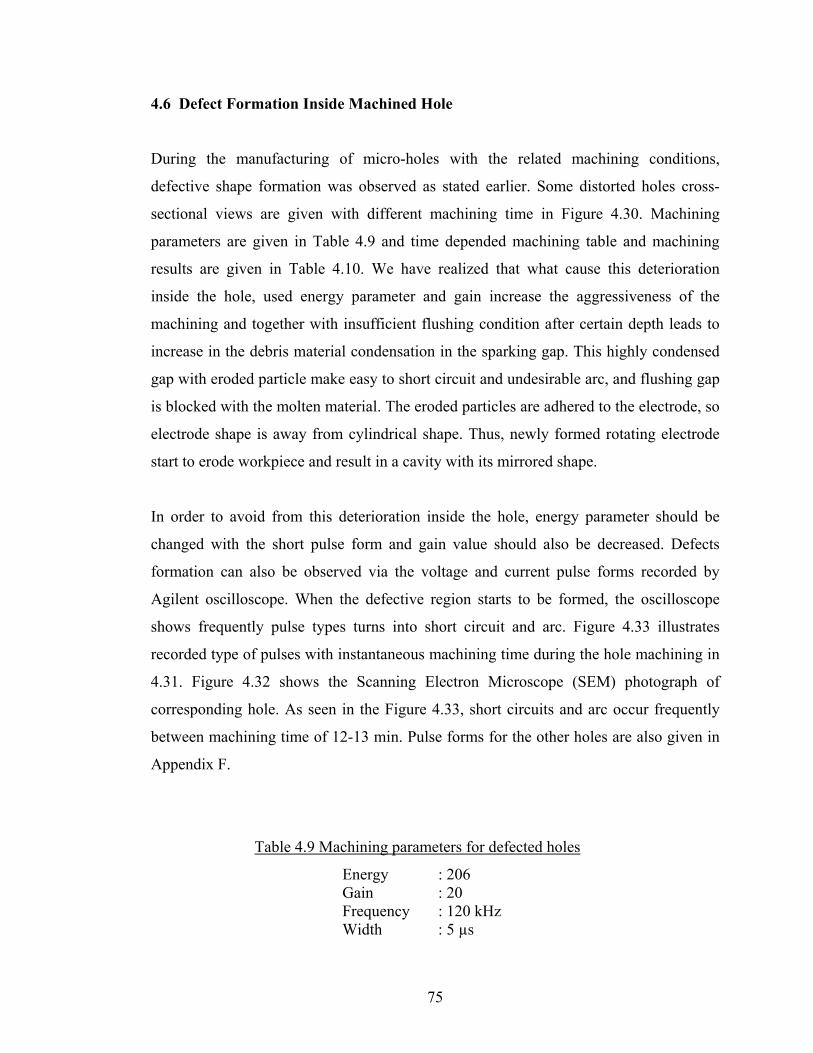
4.6 Defect Formation Inside Machined Hole
During the manufacturing of micro-holes with the related machining conditions,
defective shape formation was observed as stated earlier. Some distorted holes cross-
sectional views are given with different machining time in Figure 4.30. Machining
parameters are given in Table 4.9 and time depended machining table and machining
results are given in Table 4.10. We have realized that what cause this deterioration
inside the hole, used energy parameter and gain increase the aggressiveness of the
machining and together with insufficient flushing condition after certain depth leads to
increase in the debris material condensation in the sparking gap. This highly condensed
gap with eroded particle make easy to short circuit and undesirable arc, and flushing gap
is blocked with the molten material. The eroded particles are adhered to the electrode, so
electrode shape is away from cylindrical shape. Thus, newly formed rotating electrode
start to erode workpiece and result in a cavity with its mirrored shape.
In order to avoid from this deterioration inside the hole, energy parameter should be
changed with the short pulse form and gain value should also be decreased. Defects
formation can also be observed via the voltage and current pulse forms recorded by
Agilent oscilloscope. When the defective region starts to be formed, the oscilloscope
shows frequently pulse types turns into short circuit and arc. Figure 4.33 illustrates
recorded type of pulses with instantaneous machining time during the hole machining in
4.31. Figure 4.32 shows the Scanning Electron Microscope (SEM) photograph of
corresponding hole. As seen in the Figure 4.33, short circuits and arc occur frequently
between machining time of 12-13 min. Pulse forms for the other holes are also given in
Appendix F.
Table 4.9 Machining parameters for defected holes
Energy : 206 Gain : 20 Frequency : 120 kHz Width : 5 µs
75
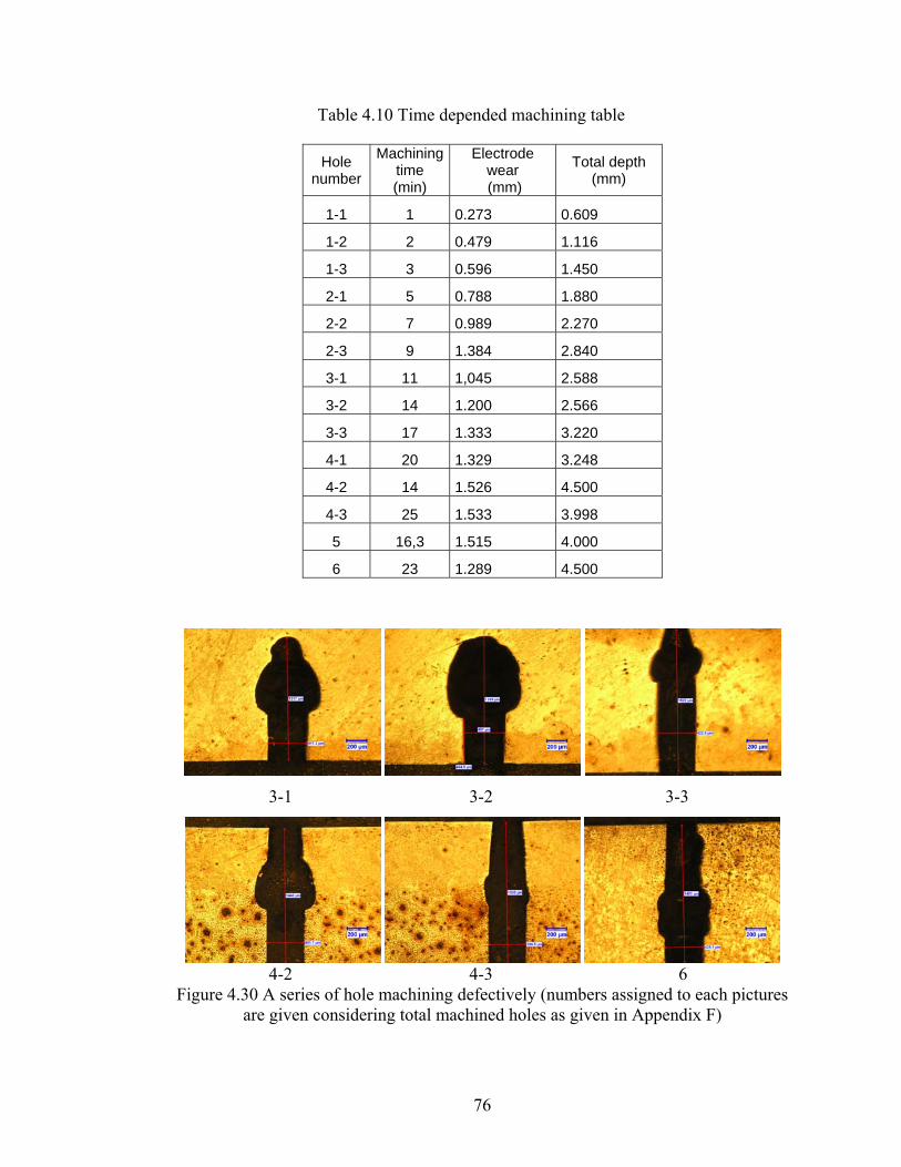
Table 4.10 Time depended machining table
Hole number
Machining time (min)
Electrode wear (mm)
Total depth (mm)
1-1 1 0.273 0.609
1-2 2 0.479 1.116
1-3 3 0.596 1.450
2-1 5 0.788 1.880
2-2 7 0.989 2.270
2-3 9 1.384 2.840
3-1 11 1,045 2.588
3-2 14 1.200 2.566
3-3 17 1.333 3.220
4-1 20 1.329 3.248
4-2 14 1.526 4.500
4-3 25 1.533 3.998
5 16,3 1.515 4.000
6 23 1.289 4.500
3-1 3-2 3-3
4-2 4-3 6
Figure 4.30 A series of hole machining defectively (numbers assigned to each pictures are given considering total machined holes as given in Appendix F)
76

Figure 4.31 Defective hole shape labeled with (4-1)
Figure 4.32 SEM photographs of defective hole from top view
2min 4 min
Figure 4.33 Recorded pulse forms of defective hole in Figure 4.31 with instant
machining time shown under the captured pulse shapes (cont).
77

7min 9 min
12min 15 min
17min 19.30 min
Figure 4.33 (cont) Recorded pulse forms of defective hole in Figure 4.31 with instant machining time shown under the captured pulse shapes.
The possible solution to eliminate the distortion inside the hole shape.
• Use of lower energy parameter and gain depending on current and voltage value
• Increase flushing pressure and clamp rotational speed
• Use of vibrating worktable such as ultrasonic vibration method
• Use of tubular electrode; it has constant flushing through the gap so the debris
can be easily removed away from the sparking area.
78
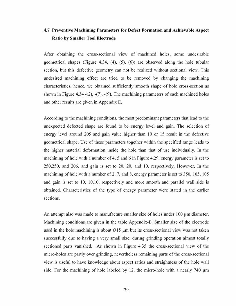
4.7 Preventive Machining Parameters for Defect Formation and Achievable Aspect
Ratio by Smaller Tool Electrode
After obtaining the cross-sectional view of machined holes, some undesirable
geometrical shapes (Figure 4.34, (4), (5), (6)) are observed along the hole tubular
section, but this defective geometry can not be realized without sectional view. This
undesired machining effect are tried to be removed by changing the machining
characteristics, hence, we obtained sufficiently smooth shape of hole cross-section as
shown in Figure 4.34 -(2), -(7), -(9). The machining parameters of each machined holes
and other results are given in Appendix E.
According to the machining conditions, the most predominant parameters that lead to the
unexpected defected shape are found to be energy level and gain. The selection of
energy level around 205 and gain value higher than 10 or 15 result in the defective
geometrical shape. Use of these parameters together within the specified range leads to
the higher material deformation inside the hole than that of use individually. In the
machining of hole with a number of 4, 5 and 6 in Figure 4.29, energy parameter is set to
250,250, and 206, and gain is set to 20, 20, and 10, respectively. However, In the
machining of hole with a number of 2, 7, and 8, energy parameter is set to 350, 105, 105
and gain is set to 10, 10,10, respectively and more smooth and parallel wall side is
obtained. Characteristics of the type of energy parameter were stated in the earlier
sections.
An attempt also was made to manufacture smaller size of holes under 100 µm diameter.
Machining conditions are given in the table Appendix-E. Smaller size of the electrode
used in the hole machining is about Ø15 µm but its cross-sectional view was not taken
successfully due to having a very small size, during grinding operation almost totally
sectioned parts vanished. As shown in Figure 4.35 the cross-sectional view of the
micro-holes are partly over grinding, nevertheless remaining parts of the cross-sectional
view is useful to have knowledge about aspect ratios and straightness of the hole wall
side. For the machining of hole labeled by 12, the micro-hole with a nearly 740 µm
79

depth was drilled by using Ø32 µm tool electrode and aspect ratio of over 20 was
obtained in 100 min.
1-2 4 5
6 7 8
Figure 4.34 Cross-sectional views of defective and smooth machined holes
80
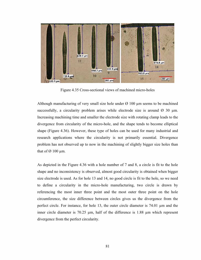
11
14
910
12 15 13
Figure 4.35 Cross-sectional views of machined micro-holes
Although manufacturing of very small size hole under Ø 100 µm seems to be machined
successfully, a circularity problem arises while electrode size is around Ø 30 µm.
Increasing machining time and smaller the electrode size with rotating clamp leads to the
divergence from circularity of the micro-hole, and the shape tends to become elliptical
shape (Figure 4.36). However, these type of holes can be used for many industrial and
research applications where the circularity is not primarily essential. Divergence
problem has not observed up to now in the machining of slightly bigger size holes than
that of Ø 100 µm.
As depicted in the Figure 4.36 with a hole number of 7 and 8, a circle is fit to the hole
shape and no inconsistency is observed, almost good circularity is obtained when bigger
size electrode is used. As for hole 13 and 14, no good circle is fit to the hole, so we need
to define a circularity in the micro-hole manufacturing, two circle is drawn by
referencing the most inner three point and the most outer three point on the hole
circumference, the size difference between circles gives us the divergence from the
perfect circle. For instance, for hole 13, the outer circle diameter is 74.01 µm and the
inner circle diameter is 70.25 µm, half of the difference is 1.88 µm which represent
divergence from the perfect circularity.
81
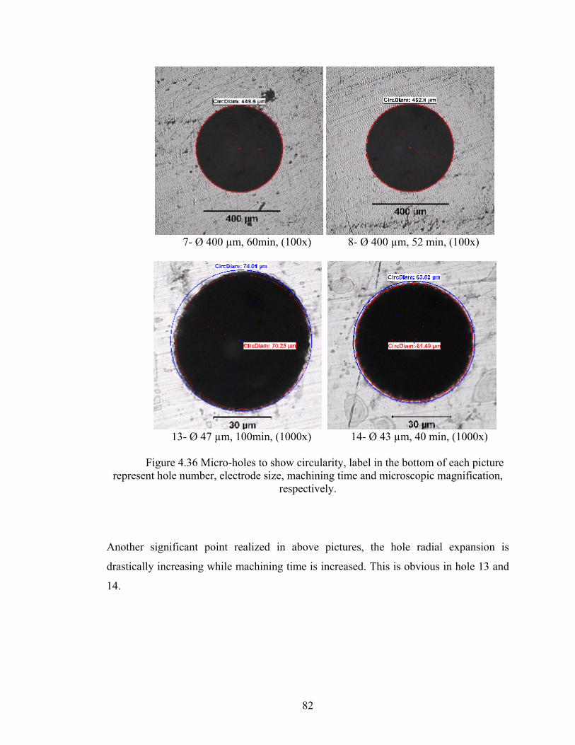
7- Ø 400 µm, 60min, (100x) 8- Ø 400 µm, 52 min, (100x)
13- Ø 47 µm, 100min, (1000x) 14- Ø 43 µm, 40 min, (1000x) Figure 4.36 Micro-holes to show circularity, label in the bottom of each picture
represent hole number, electrode size, machining time and microscopic magnification, respectively.
Another significant point realized in above pictures, the hole radial expansion is
drastically increasing while machining time is increased. This is obvious in hole 13 and
14.
82
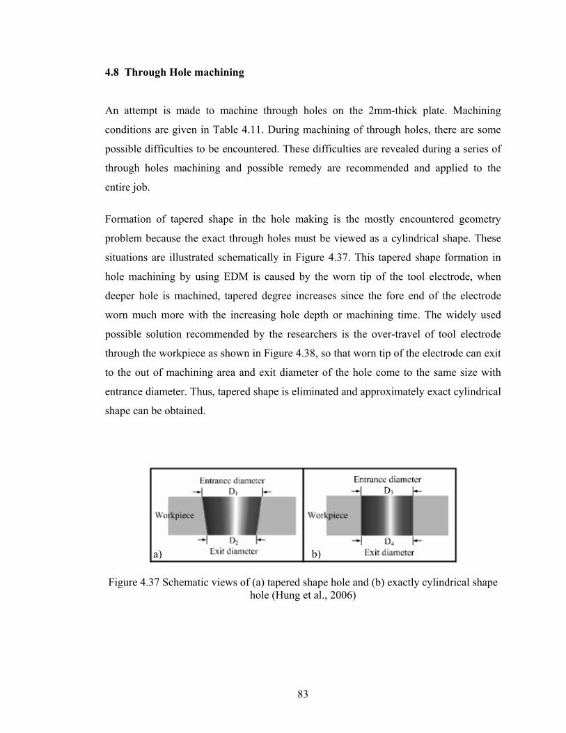
4.8 Through Hole machining An attempt is made to machine through holes on the 2mm-thick plate. Machining
conditions are given in Table 4.11. During machining of through holes, there are some
possible difficulties to be encountered. These difficulties are revealed during a series of
through holes machining and possible remedy are recommended and applied to the
entire job.
Formation of tapered shape in the hole making is the mostly encountered geometry
problem because the exact through holes must be viewed as a cylindrical shape. These
situations are illustrated schematically in Figure 4.37. This tapered shape formation in
hole machining by using EDM is caused by the worn tip of the tool electrode, when
deeper hole is machined, tapered degree increases since the fore end of the electrode
worn much more with the increasing hole depth or machining time. The widely used
possible solution recommended by the researchers is the over-travel of tool electrode
through the workpiece as shown in Figure 4.38, so that worn tip of the electrode can exit
to the out of machining area and exit diameter of the hole come to the same size with
entrance diameter. Thus, tapered shape is eliminated and approximately exact cylindrical
shape can be obtained.
a) b)
Figure 4.37 Schematic views of (a) tapered shape hole and (b) exactly cylindrical shape hole (Hung et al., 2006)
83
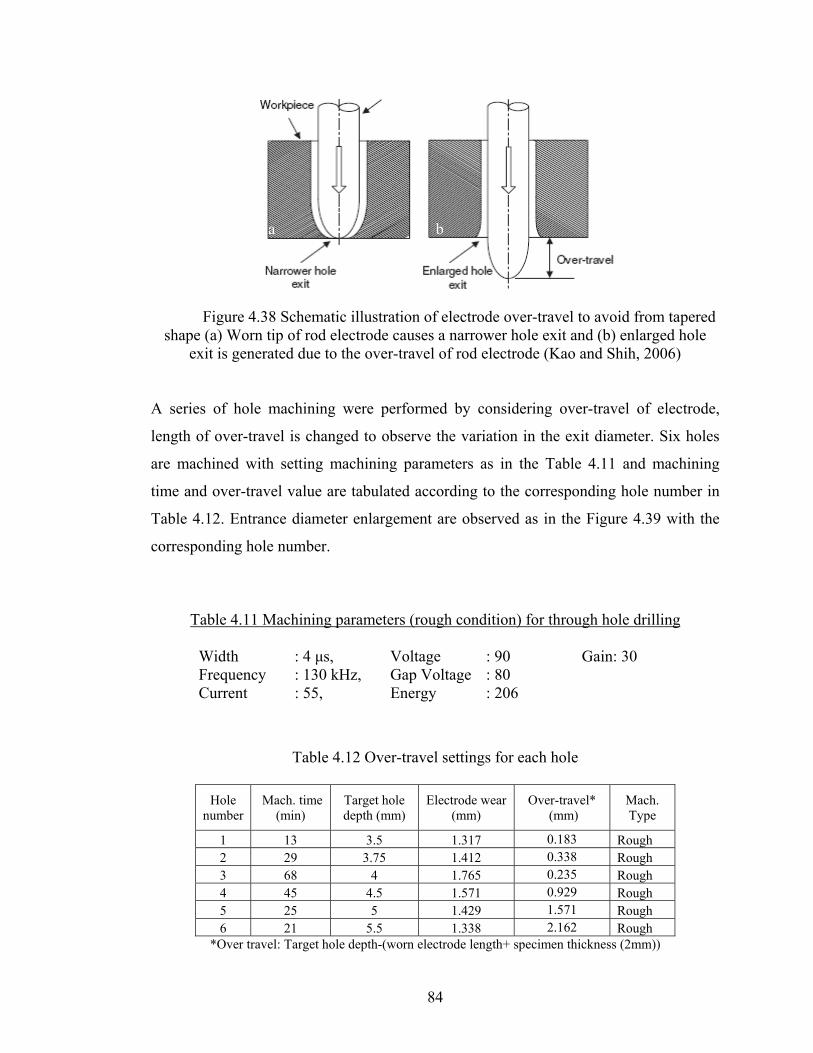
a b
Figure 4.38 Schematic illustration of electrode over-travel to avoid from tapered
shape (a) Worn tip of rod electrode causes a narrower hole exit and (b) enlarged hole exit is generated due to the over-travel of rod electrode (Kao and Shih, 2006)
A series of hole machining were performed by considering over-travel of electrode,
length of over-travel is changed to observe the variation in the exit diameter. Six holes
are machined with setting machining parameters as in the Table 4.11 and machining
time and over-travel value are tabulated according to the corresponding hole number in
Table 4.12. Entrance diameter enlargement are observed as in the Figure 4.39 with the
corresponding hole number.
Table 4.11 Machining parameters (rough condition) for through hole drilling
Width : 4 μs, Voltage : 90 Gain: 30 Frequency : 130 kHz, Gap Voltage : 80 Current : 55, Energy : 206
Table 4.12 Over-travel settings for each hole
Hole number
Mach. time (min)
Target hole depth (mm)
Electrode wear (mm)
Over-travel* (mm)
Mach. Type
1 13 3.5 1.317 0.183 Rough 2 29 3.75 1.412 0.338 Rough 3 68 4 1.765 0.235 Rough 4 45 4.5 1.571 0.929 Rough 5 25 5 1.429 1.571 Rough 6 21 5.5 1.338 2.162 Rough
*Over travel: Target hole depth-(worn electrode length+ specimen thickness (2mm))
84
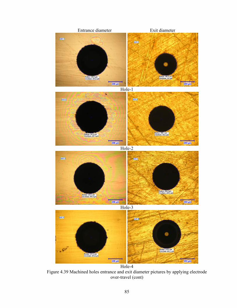
Entrance diameter Exit diameter
Hole-1
Hole-2
Hole-3
Hole-4
Figure 4.39 Machined holes entrance and exit diameter pictures by applying electrode over-travel (cont)
85

Hole-5
Hole-6
Figure 4.39 (cont) Machined holes entrance and exit diameter pictures by applying electrode over-travel.
We have proposed a classical EDM approach to produce micro-holes with lower
difference between entrance and exit diameter, and obtain better surface roughness, this
technique can be applied by introducing second electrode after the first machining
operations. Machining with new electrode and setting finish machining parameters
provide better circularity, good surface roughness, and lower tapered shape when
compared to the machining only applying electrode over-travel. There is no repetition
problem when exact machining coordinate is found to be ready after cutting used
electrode tip since Sarix machine has a high resolution of 1µm working table moving
along –x and –y axis. The first machining is done using rough machining parameters but
the second machining is done by using finish machining parameters and second
machining time is very small according to the first one, because previously machined
holes provide good flushing condition. The finish parameter is different from rough
machining parameter in the energy parameter and frequency, 100 and 150 kHz are used
86
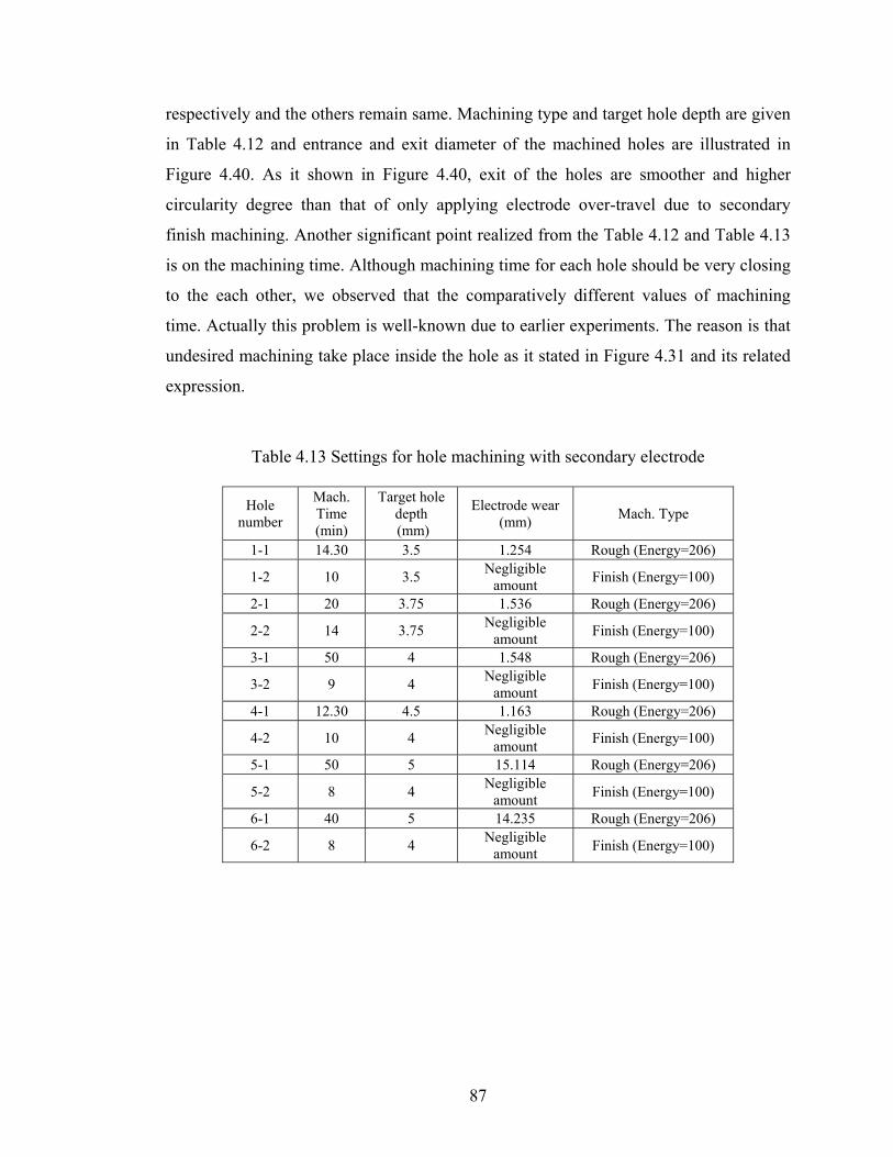
respectively and the others remain same. Machining type and target hole depth are given
in Table 4.12 and entrance and exit diameter of the machined holes are illustrated in
Figure 4.40. As it shown in Figure 4.40, exit of the holes are smoother and higher
circularity degree than that of only applying electrode over-travel due to secondary
finish machining. Another significant point realized from the Table 4.12 and Table 4.13
is on the machining time. Although machining time for each hole should be very closing
to the each other, we observed that the comparatively different values of machining
time. Actually this problem is well-known due to earlier experiments. The reason is that
undesired machining take place inside the hole as it stated in Figure 4.31 and its related
expression.
Table 4.13 Settings for hole machining with secondary electrode
Hole number
Mach. Time (min)
Target hole depth (mm)
Electrode wear (mm) Mach. Type
1-1 14.30 3.5 1.254 Rough (Energy=206)
1-2 10 3.5 Negligible amount Finish (Energy=100)
2-1 20 3.75 1.536 Rough (Energy=206)
2-2 14 3.75 Negligible amount Finish (Energy=100)
3-1 50 4 1.548 Rough (Energy=206)
3-2 9 4 Negligible amount Finish (Energy=100)
4-1 12.30 4.5 1.163 Rough (Energy=206)
4-2 10 4 Negligible amount Finish (Energy=100)
5-1 50 5 15.114 Rough (Energy=206)
5-2 8 4 Negligible amount Finish (Energy=100)
6-1 40 5 14.235 Rough (Energy=206)
6-2 8 4 Negligible amount Finish (Energy=100)
87

Entrance diameter Exit diameter
Hole-1
Hole-2
Hole-3
Hole-4
Figure 4.40 Entrance and exit diameter photos of holes machined by using two electrodes (cont).
88
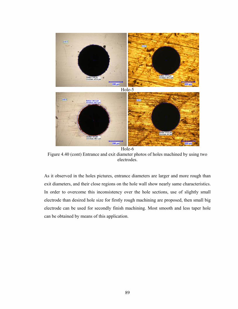
Hole-5
Hole-6
Figure 4.40 (cont) Entrance and exit diameter photos of holes machined by using two electrodes.
As it observed in the holes pictures, entrance diameters are larger and more rough than
exit diameters, and their close regions on the hole wall show nearly same characteristics.
In order to overcome this inconsistency over the hole sections, use of slightly small
electrode than desired hole size for firstly rough machining are proposed, then small big
electrode can be used for secondly finish machining. Most smooth and less taper hole
can be obtained by means of this application.
89

CHAPTER 5
CONCLUSIONS AND FUTURE WORK
Micro-electrical discharge machining process is a widely used micro fabrication
technique to produce micro-parts and components needed in the micro-mechatronic
systems and industrial applications. Micro-EDM technique was discussed extensively by
using previous literatures. Micro-hole fabrication is a primary task for this thesis because
micro-hole is the most simple and widely used micro products that can be manufactured
by using micro-EDM.
Manufacturing of micro-holes by using micro-EDM is the first completed study on
micro-EDM in Turkey. For this purpose, Sarix high precision micro-EDM machine was
purchased from Switzerland and it has many undisclosed parameters which are effective
in the determination of machining characteristics. In order to reveal the machining
characteristics and predict the machined shape of holes, this thesis is completed with the
outstanding concluding remarks.
The statements below can be concluded from the experimental results and observations;
1- Energy parameter is the most predominant parameter which assigns the type of
pulses produced by the micro-erosion generator. According to captured pulse
form results, approximately 125 ns and 1 µs discharge time are recorded when
energy parameter are set to 14 and 205, respectively. The peak current read from
the oscilloscope are approximately 5 A and 15 A while considering the former
energy parameter, respectively.
90

2- By using higher the energy parameter, higher discharge time and peak current,
results in higher hole depth while surface roughness and shape of holes go to be
distorted. In addition, electrode removal also increases with the mentioned
energy parameter.
3- Expansion in the hole diameter increases with the increasing machining time and
longer the voltage pulse. However, less consistency in the holes diameter is
obtained.
4- Narrower section length of a hole, end tip of the hole, start to be formed after
where the 5% reduction of hole entrance diameter is measured.
5- By using higher the width and lower the frequency, higher hole depth can be
obtained but the frequency value must always greater than time width.
6- Open voltage and gap voltage should be close to each other, approximately 5 V
or 10 V difference is suitable for effective machining.
7- Lower gain value should be used, approximately 10, in order to prevent the
undesired shape formation inside the hole.
8- Approximately 20 aspect ratios are obtained by using Ø100 µm tool electrode.
9- Circularity of the micro-holes around Ø30 µm size is away from the correct
circle which turns into the elliptical shape when the higher machining time
approximately 100 min. is applied.
As future work;
With the completion of this thesis, machining characteristics and machining behavior of
micro-EDM can be estimated and predicted easily. By using the approved machining
parameters, through micro-holes with a diameter less than 50 µm can be performed to
analyze aspect ratios, surface roughness, circularity, and straightness of the hole wall-
side in detail. A software based model can be developed to predict the machined hole
geometry in advance by considering end tip shape and cross-sectional view. This model
provides us to save waste of time consumed during the sacrificial experiments.
91

92
In this study, dielectric oil is used as a flushing liquid, dielectric liquid can be changed to
different dielectric liquid, such as dielectric water or kerosene, and efficiency on the
machined parts can be compared. Apart from the micro-hole manufacturing, a study can
be focused on the manufacturing of micro-channels widely used for micro-cooling
systems or 3D machining can performed to produce mini/micro complex shape parts or
cavities.
By using the recommended machining parameters in the thesis, all the planned micro
machining process by micro-EDM can be achieved successfully.

REFERENCES 1. Allen, P., Chen, X., 2007 “Process simulation of micro electro-discharge
machining on molybdenum” J. Mater. Process. Technol. 186 346-355.
2. Chung, D.K., Kim, B.H., Chu, C.N., 2007 “Micro electrical discharge milling
using deionized water as a dielectric fluid”, J. Micromech. Microeng. 17 867-874.
3. Cao, D.M., Jiang, J., Meng, W.J., Jiang, J.C., Wang, W., 2007 “Fabrication of
high-aspect-ratio microscale Ta mold inserts with micro electrical discharge
machining”, Microsystem Technologies 13 503-510
4. Diver, C., Atkinson, J., Helml, H.J., Li, L., 2004 “Micro-EDM drilling of tapered
holes for industrial applications”, J. Mater. Process. Technol. 149 296-303.
5. Dhanik, S., Joshi, S.S., 2005 “Modeling of a Single Resistance Capacitance Pulse
Discharge in Micro-Electro Discharge Machining”, Journal of Manufacturing
Science and Engineering, 127 759-767.
6. Ekmekçi, B., 2004 “Theoretical and Experimental Investigation of Residual
Stresses in Electric Discharge Machining”, PhD Thesis, METU.
7. Erden, A., 1977 “Theoretical and Experimental Investigation on Electric
Discharge Machining”, PhD Thesis, METU.
8. Fleischer, J., Masuzawa, T., Schmidt, J., Knoll, M., 2004 “New applications for
micro-EDM”, J. Mater. Process. Technol. 149 246-249.
9. Gangadhar, A., Sunmugam, M.S., Philip, P.K., 1992 “Pulse train studies in EDM
with controlled pulse relaxation” Int. J. Machine Tools Manuf. 32 651-657.
93
10. Ho, K.H., Newman, S. T., 2003 “State of the art electrical discharge machining
(EDM)”, Int. J. Machine Tools Manuf. 43 1287-1300.
11. Han, F., Chen, L., Yu, D., Zhou, X., 2007 “Basic study on pulse generator for
micro-EDM” Int. J. Adv. Manuf. Tech. 33 474-479.
12. Han, F., Yamada, Y., Kawakami, T., Kunieda, M., 2006 “Experimental attempts
of sub-micrometer order size machining using micro-EDM”, Precis. Eng. 30 123-
131.
13. Her, M.G., Weng, F.T., 2001 “Micro-hole Machining of Copper Using the
Electro-discharge Machining Process with a Tungsten Carbide Electrode Compared
with a Copper Electrode”, Int. J. Adv. Manuf. Tech. 17 715-719.
14. Hung, J.C., Lin, J.K., Yan, B.H., Liu, H.S., Ho, P.H., 2006 “Using a helical
micro-tool in micro-EDM combined with ultrasonic vibration for micro-hole
machining”, J. Micromech. Microeng. 16 2705-2713.
15. Hung, J.C., Yan, B.H., Liu, H.S., Chow, H.M., 2006 “Micro-hole machining
using micro-EDM combined with electropolishing”, J. Micromech. Microeng. 16
1480-1486.
16. Kao, C.C., Shih, A.J., 2006 “Sub-nanosecond monitoring of micro-hole
electrical discharge machining pulses and modeling of discharge ringing”, Int. J.
Machine Tools Manuf. 46 1996-2008.
17. Kim, Y.T., Park, S.J., Lee, S.J., 2005 “Micro/Meso-scale Shapes Machining by
Micro EDM Process” Int. Journal of Precision Eng. And Manufacturing 6 5-11.
18. Klocke, F., Lung, D., Antonoglou, G., Thomaidis, D., 2004 “The effects of
powder suspended dielectrics on the thermal influenced zone by electrodischarge
machining with small discharge energies” J. Mater. Process. Technol. 149 191-197.
94

19. Kim, D.J., Yi, S.M., Lee, Y.S.,Chu, C.N., 2006 “Straight hole micro EDM with a
cylindrical tool using a variable capacitance method accompanied by ultrasonic
vibration”, J. Micromech. Microeng. 16 1092-1097.
20. Kaminski, P.C., Capuano, M.N., 2003 “Micro hole machining by conventional
penetration electrical discharge machine”, Int. J. Machine Tools Manuf. 43 1143-
1149.
21. Liu, H.S., Yan, B.H., Huang, F.Y., Qiu, K.H., 2005 “A study on the
characterization of high nickel alloy micro-holes using micro-EDM and their
applications” J. Mater. Process. Technol. 169 418-426.
22. Lin, C.T., Chow, H.M., Yang, L.D., Chen, Y.F., 2007 “Feasibility study of
micro-slit EDM machining using pure water” Int. J. Adv. Manuf. Tech. 34 104-110.
23. Li, Y., Guo, M., Zhou, Z., Hu, M., 2002 “Micro electro discharge machine with
an inchworm type of micro feed mechanism” Precision Eng., J. of the Int. Societies.
for Precision Eng. and Nanotechnology 26 7-14.
24. Li, H., Senturia, S.D., 1992 “Molding of Plastic Components Using Micro-EDM
Tools” Thirteenth IEEE/CHMT International Electronics Manufacturing Technology
Symposium, 145-149.
25. Lim, H.S., Wong, Y.S., Rahman, M., Edwin Lee, M.K., 2003 “A study on the
machining of high-aspect ratio micro-structures using micro-EDM” J. Mater.
Process. Technol. 140 318-325.
26. Masuzawa, T., 2000 “State of the art of micromachining” Ann. CIRP 49 473-488.
27. Masuzawa, T., Tsukamota, J., Fujino, M., 1989 “ Drilling of Deep Microholes by
EDM”, Ann. CIRP 38 195-198.
28. Masuzawa, T., Fujimoto M, Kobayashi, K., 1985 “Wire electro-discharge
grinding for micromachining” Ann. CIRP 34 431-434.
95
29. Masuzawa, T., 1997 “Three-dimensional micro-machining by machine tools”
Ann. CIRP 46 621-628.
30. Moylan, S.P., Chandrasekar, S., Benavides,G.L., 2005 “High-Speed Micro-
Electro-Discharge Machining” Sandia Report, Sandia National Laboratories,
SAND2005-5023, Printed September.
31. Murali, M., Yeo, S.H., 2004 “Rapid Biocompatible Micro Device Fabrication by
Micro Electro-Discharge Machining”, Biomedical Microdevices 6:1, 41-45, 2004
Kluwer Academic Publishers, Manufactured in The Netherlands.
32. Nakaoku, H., Masuzawa, T., Fujino, M., 2007 “Micro-EDM of sintered
diamond”, J. Mater. Process. Technol. 187-188 274-278
33. Pham, D.T., Ivanov, A., Bigot, S., Popov, K., Dimov, S., 2007 “An investigation
of tube and rod electrode wear in micro EDM drilling”, Int. J. Adv. Manuf. Tech. 33
103-109.
34. Qu, J., 2002 “Development of cylindrical wire electrical discharge machining
process and investigation of surface integrity and mechanical property of edm
surface layers”, PhD Thesis, North Carolina State University.
35. Rajurkar, K.P., Yu, Z.Y., 2000 “3D Micro-EDM Using CAD/CAM”, Ann. CIRP
49 127-130.
36. Rajurkar, K.P., Navelkar, V.V., Springer J.E., 1987 “High speed pulse train
analysis for real-time EDM control”, SME Technical Paper.
37. Sarix Operating Manual version 1.20 for SX-100 Micro-Erosion Machine.
38. Son, S., Lim, H., Kumar, A.S., Rahman, M., 2007 “Influences of pulsed power
condition on the machining properties in micro-EDM” J. Mater. Process. Technol.
190 73-76.
96

39. Takahata, K., Shibaike, N., Guckel, H., 1999 “A Novel Micro Electro-Discharge
Machining Method Using Electrodes Fabricated by The LIGA Process” Twelfth
IEEE Int. Conference on MEMS 238-243.
40. Tsai, Y.Y., Masuzawa, T., 2004 “An index to evaluate the wear resistance of the
electrode in micro-EDM” J. Mater. Process. Technol. 149 304-309.
41. Takahata, K., Gianchandani, Y.B., 2002 “Batch Mode Micro-Electro-Discharge
Machining” Journal of Microelectromechanical systems 11 102-110.
42. Tseng, S.C., Chen, Y.C., Kuo, C.L., 2005 “A study of integration of LIGA and
M-EDM technology on the microinjection molding of ink-jet printers’ nozzle plates”,
Microsystem Technologies 12 116-119.
43. Uhlmann, E., Piltz, S., Doll, U., 2005 “Machining of micro/miniature dies and
moulds by electrical discharge machining-Recent development”, J. Mater. Process.
Technol. 167 488-493.
44. Wang, A.C., Yan, B.H., Tang, Y.X., Huang, F.Y., 2005 “The feasibility study on
a fabricated micro slit die using micro EDM”, Int. J. Adv. Manuf. Tech. 25 10-16.
45. Wansheng, Z. Zhenlong, W., Shichun, D., Guanxin, C., Hongyu, W., 2002
“Ultrasonic and electric discharge machining to deep and small hole on titanium
alloy”, J. Mater. Process. Technol. 120 101-106.
46. Weng, F.T., 2006 “Electrodischarge machining of a coaxial array of microholes
using a graphite-copper electrode”, Int. J. Adv. Manuf. Tech 27 1097-1100.
47. Wong, Y.S., Rahman, M., Lim, H.S., Han, H., Ravi, N., 2003 “Investigation of
micro-EDM material removal characteristics using single RC-pulse discharges”, J.
Mater. Process. Technol. 140 303-307
48. Yamazaki, M., Suziki, T., Mori, N., Kunieda M., 2004 “EDM of micro-rods by
self-drilled holes”, J. Mater. Process. Technol. 149134-138.
97

98
49. Yan, B.H., Wang, A.C., Huang, C.Y., Huang, F.Y., 2002 “Study of precision
micro-holes in borosilicate glass using micro EDM combined with micro ultrasonic
vibration machining”, Int. J. Machine Tools Manuf. 42 1105-1112.
50. Yeo, S.H., Murali, M., Cheah, H.T., 2004 “Magnetic field assisted micro electro-
discharge machining”, J. Micromech. Microeng. 14 1526-1529.
51. Yu, Z., Masuzawa, T., Fujino, M., 1998 “Micro-EDM for Three Dimensional
Cavities-Development of Uniform Wear Method”, Ann. CIRP. 47 169-172.
52. Yu, Z.Y., Rajurkar, K.P., Shen, H., 2002 “High Aspect Ratio and Complex
Shaped Blind Micro Holes by Micro EDM”, Ann. CIRP 51 359-362.
53. Zhao, W., Yang, Y., Wang, Z., Zhang, Y., 2004 “A CAD/CAM system for
micro-ED-milling of small 3D freeform cavity”, J. Mater. Process. Technol 149 573-
578.
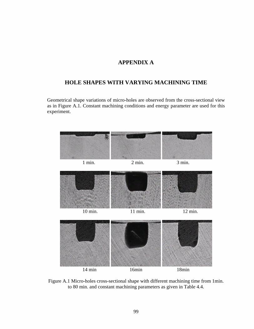
APPENDIX A
HOLE SHAPES WITH VARYING MACHINING TIME
Geometrical shape variations of micro-holes are observed from the cross-sectional view as in Figure A.1. Constant machining conditions and energy parameter are used for this experiment.
1 min. 2 min. 3 min.
10 min. 11 min. 12 min.
14 min 16min 18min
Figure A.1 Micro-holes cross-sectional shape with different machining time from 1min.
to 80 min. and constant machining parameters as given in Table 4.4.
99

20 min. 22 min 24 min.
26 min. 28 min. 30 min.
32 min 34 min. 36 min.
38 min 40 min. 42 min. Figure A.1 (cont) Micro-holes cross-sectional shape with different machining time from
1min. to 80 min. and constant machining parameters as given in Table 4.4.
100
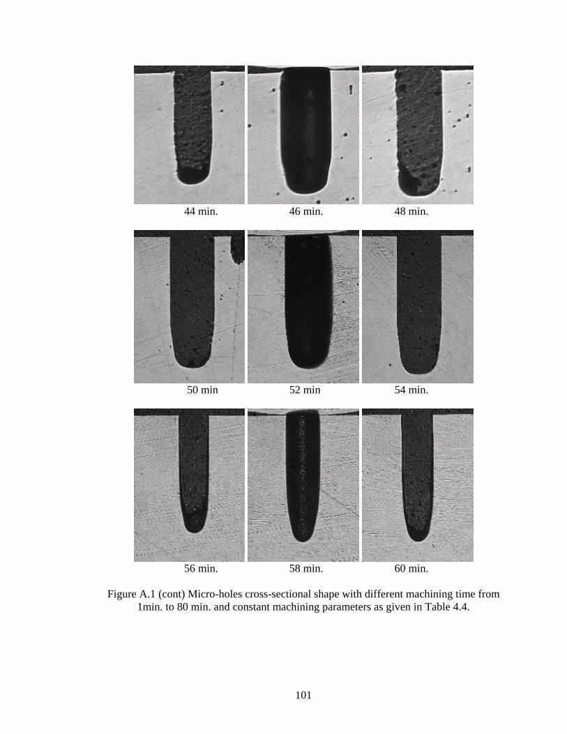
44 min. 46 min. 48 min.
50 min 52 min 54 min.
56 min. 58 min. 60 min.
Figure A.1 (cont) Micro-holes cross-sectional shape with different machining time from
1min. to 80 min. and constant machining parameters as given in Table 4.4.
101

62min 64min 66min
70 min. 75 min. 80 min.
Figure A.1 (cont) Micro-holes cross-sectional shape with different machining time from 1min. to 80 min. and constant machining parameters as given in Table 4.4.
102

APPENDIX B
HOLE SHAPES WITH VARYING TIME WIDTH
Diameter variations of micro-holes are illustrated in Figure B.1 and cross-sectional
shape of machined holes are given in Figure B.2. Machining was repeated three times
for the same width to verify the repeatability of experiments.
11 2 3
Width: 0.1 µs
1 2 3
Width: 0.5 µs
Figure B.1 Micro-hole photographs from top view by using variant width time
103

1 2 3
Width: 1 µs
1 2 3Width: 2 µs
1 2 3
Width: 6 µs
1 2 3
Width: 8 µs
Figure B.1 (cont) Micro-hole photographs from top view by using variant width time
104

1 2 3
Width: 0.1 µs
1 2 3Width: 0.5 µs
1 2 3Width: 1 µs
1 2 3Width: 6 µs
Figure B.2 Cross-sectional photographs of micro-holes by using variant width time.
105

106
Width: 8 µs 1 2 3
Figure B.2 (cont) Cross-sectional photographs of micro-holes by using variant width
time.

APPENDIX C
HOLES SHAPES WITH VARYING FREQUENCY
Micro-holes were machined to see the effect of frequency is illustrated in Figure C.1.
Each machining repeated three times to verify the reliability of results.
1 2 3
10 kHz
1 2 325 kHz
1 2 3
50 kHz
Figure C.1 Micro hole photographs machined with different frequency values of 10 kHz, 25 kHz, 50 kHz, 100 kHz, and 150 kHz r for each row, respectively.
107
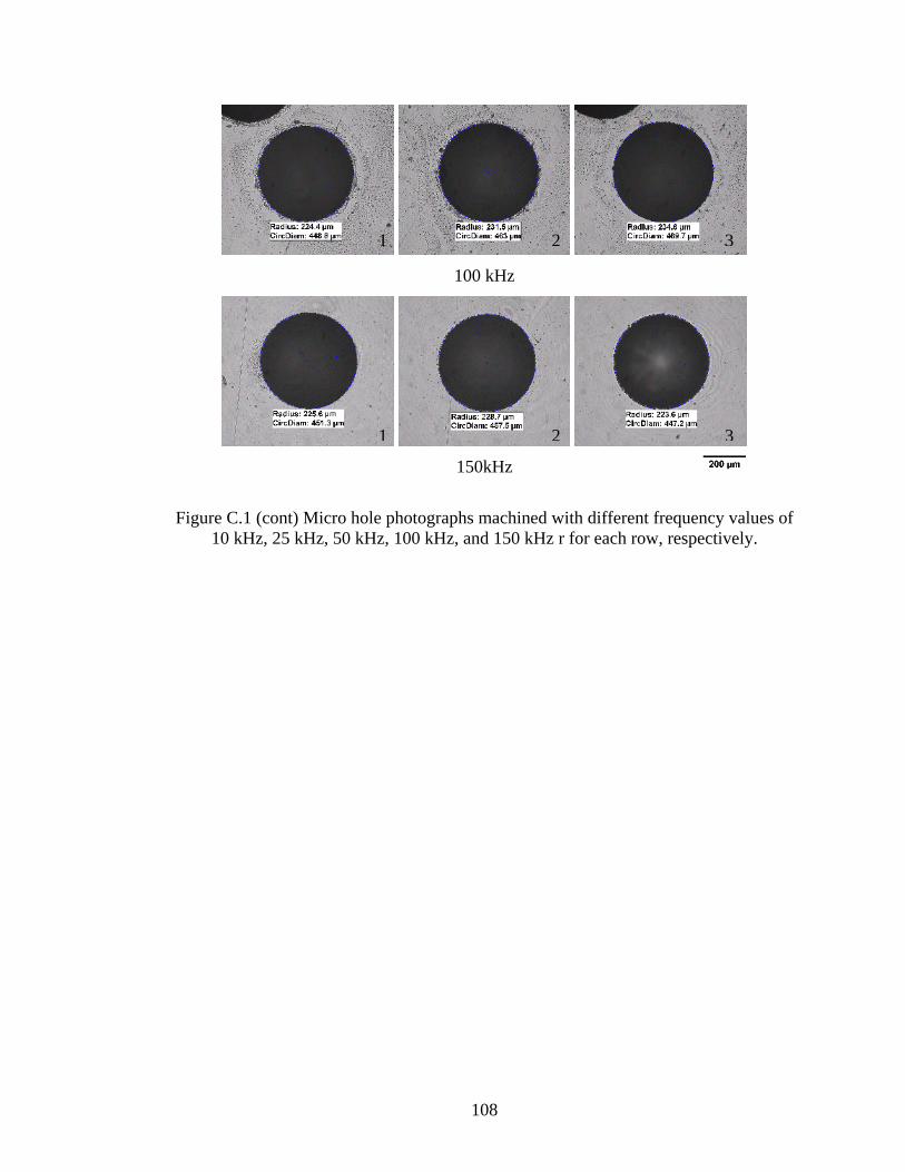
1 2 3
100 kHz
1 2 3
150kHz
Figure C.1 (cont) Micro hole photographs machined with different frequency values of
10 kHz, 25 kHz, 50 kHz, 100 kHz, and 150 kHz r for each row, respectively.
108
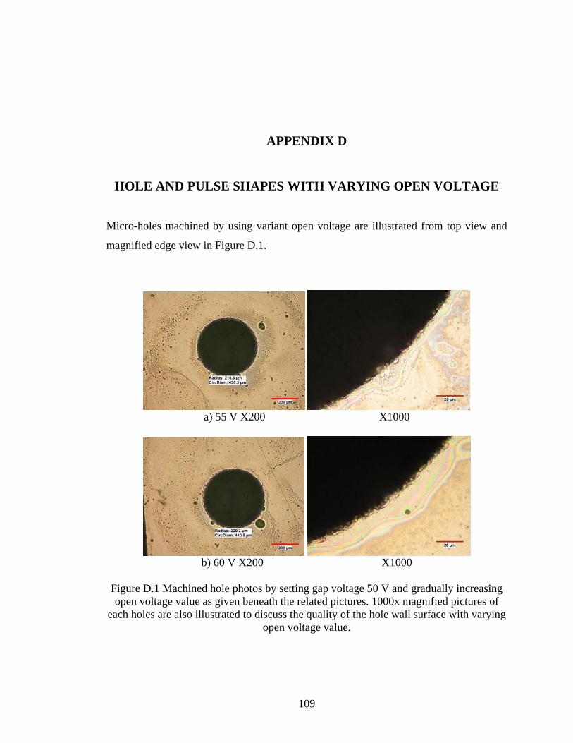
APPENDIX D
HOLE AND PULSE SHAPES WITH VARYING OPEN VOLTAGE
Micro-holes machined by using variant open voltage are illustrated from top view and
magnified edge view in Figure D.1.
a) 55 V X200 X1000
b) 60 V X200 X1000
Figure D.1 Machined hole photos by setting gap voltage 50 V and gradually increasing open voltage value as given beneath the related pictures. 1000x magnified pictures of
each holes are also illustrated to discuss the quality of the hole wall surface with varying open voltage value.
109
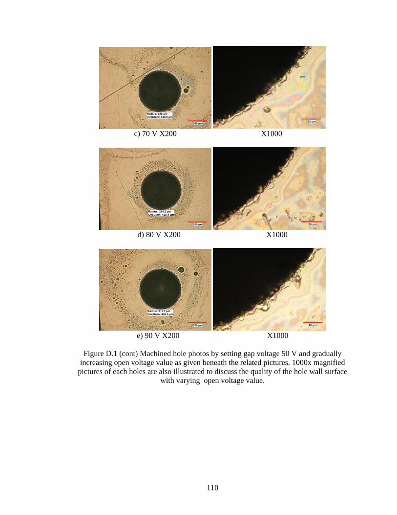
c) 70 V X200 X1000
d) 80 V X200 X1000
e) 90 V X200 X1000
Figure D.1 (cont) Machined hole photos by setting gap voltage 50 V and gradually
increasing open voltage value as given beneath the related pictures. 1000x magnified pictures of each holes are also illustrated to discuss the quality of the hole wall surface
with varying open voltage value.
110
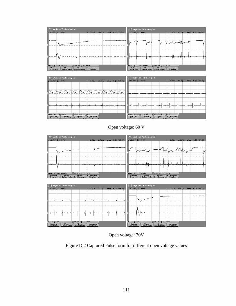
Open voltage: 60 V
Open voltage: 70V
Figure D.2 Captured Pulse form for different open voltage values
111
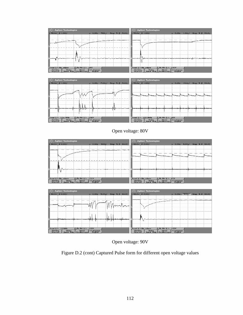
Open voltage: 80V
Open voltage: 90V
Figure D.2 (cont) Captured Pulse form for different open voltage values
112
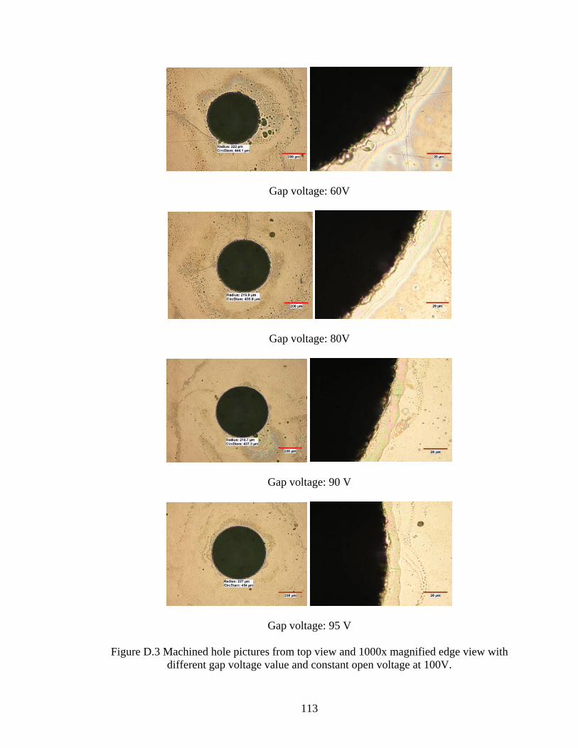
Gap voltage: 60V
Gap voltage: 80V
Gap voltage: 90 V
Gap voltage: 95 V
Figure D.3 Machined hole pictures from top view and 1000x magnified edge view with different gap voltage value and constant open voltage at 100V.
113

Gap voltage: 60 V
Gap voltage: 80 V
Figure D.4 Voltage and current pulse forms for different gap voltage while open voltage kept constant at 100V.
114
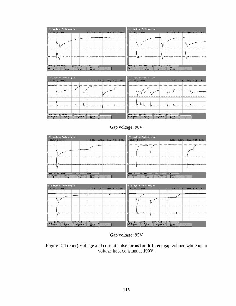
Gap voltage: 90V
Gap voltage: 95V Figure D.4 (cont) Voltage and current pulse forms for different gap voltage while open
voltage kept constant at 100V.
115

Table D.1 Machining results for varying gap voltage
Gap
Voltage (V)
Target hole depth (mm)
Electrode removal
(mm)
1,74 0.41
1,79 0,44 95
1,7 0,364
1,3047 0,129 *
1,62 0,392 90
1,5454 0,368
1,2029 0,371
1,53 0,426 80
1,67 0,477
1,659 (44 min) 0,539
1,92 (41min) 0,638 60
1,51 0,475 ** * The worn tip of electrode was not cut back sufficiently after the previous machining, some black spot (carbon) was observed over the tip of the electrode, so which results in the smaller target depth because carbon particle over the electrode decrease chance of discharge. ** Gap voltage is set to 75 V by accident up to 0.39mm target depth during machining
116

APPENDIX E
MACHINING RESULTS FOR MICRO-HOLE DRILLING WITH Ø100 µm TOOL ELECTRODE
Table E.1 Machining results by using 100 µm diameter of electrode
Mach. time (min)
Target hole depth (mm)
Hole diameter
(µm)
Electrode removal (mm)
Energy parameter
15 1,5 182,00 1,3 350 15,3 1,33 179,50 0,927 350 15 0,73 180,00 0,486 350 60 0,16 160,00 0,053 114 60 0,165 162,00 0,047 105 60 2,13 159,30 0,422 14 60 1,6 162,40 0,298 14 60 2,16 174,60 0,416 14 60 2,13 174,20 0,448 14 40 1.925 168,00 0,38 14 40 1,86 156,80 0,363 14 44 1,86 157,00 0,358 14 30 1.796 167,50 0,332 14 20 1,21 163,00 0,198 14 20 1,16 156,90 0,17 14 10 0,615 145,50 0,084 14 10 0,64 154,40 0,095 14 13 0,793 140,50 0,109 14
117

Energy: 350
Energy: 14
Figure E.1 Pulse shapes for 100 µm diameter of electrode by using energy parameter 350 and 14.
118

Table E.2 Machining results with the corresponding machining parameters
number diameter Machining
( (mm)
Electrode Machining Parameters
Hole Electrode
(μm) time min.)
Target depth wear
(mm)
1 400 15 3 1.299 Width:5 Freq:100 Open voltage:90 Gap:85 Energy:350 Gain: 10
2 192 8 2.5 1.35 Width:5 Freq:100 Open voltage:90 Gap:85 Energy:350 Gain: 10
4 400 14 3 1.28 Width:4 Freq:120 Open voltage:90 Gap:80 Energy:250 Gain:20
5 400 20 3 1.28 Width:4 Freq:120 Open voltage:90 Gap:80 Energy:250 Gain:20
6 400 33 3 1.266 Width:5 Freq:100 Open voltage:90 Gap:85 Energy:206 Gain:10
7 400 60 2 0.479 Width:5 Freq:100 Open voltage:90 Gap:85 Energy:105 Gain:10
8 400 52 2 0.459 Width:5 Freq:100 Open voltage:90 Gap:85 Energy:105 Gain:10
9 48 55 1.19 0.626 Width:2 Freq:120 Open voltage:80 Gap:75 Energy:14 Gain:5
10 35 50 1 0.408 Width:2 Freq:120 Open voltage:80 Gap:75 Energy:14 Gain:5
11 38 50 1.14 0.72 Width:2 Freq:120 Open voltage:80 Gap:75 Energy:14 Gain:5
12 32 100 1.06 0.4 Width:2 Freq:120 Open voltage:80 Gap:75 Energy:13 Gain:5
13 47 100 1.57 0.899 Width:2 Freq:120 Open voltage:80 Gap:75 Energy:14 Gain:5
14 43 40 0.86 0.397 Width:2 Freq:120 Open voltage:80 Gap:75 Energy:14 Gain:5
15 40 60 1.06 0.562 Width:2 Freq:120 Open voltage:80 Gap:75 Energy:14 Gain:5
16 22 50 0.84 0.125 Width:2 Freq:120 Open voltage:80 Gap:75 Energy:14 Gain:5
17 15 30 0.65 0.112 Width:2 Freq:120 Open voltage:80 Gap:75 Energy:14 Gain:5 Width μs, Frequency kHz, Open voltage V, Gap V, unit is not defined for the other parameters
119
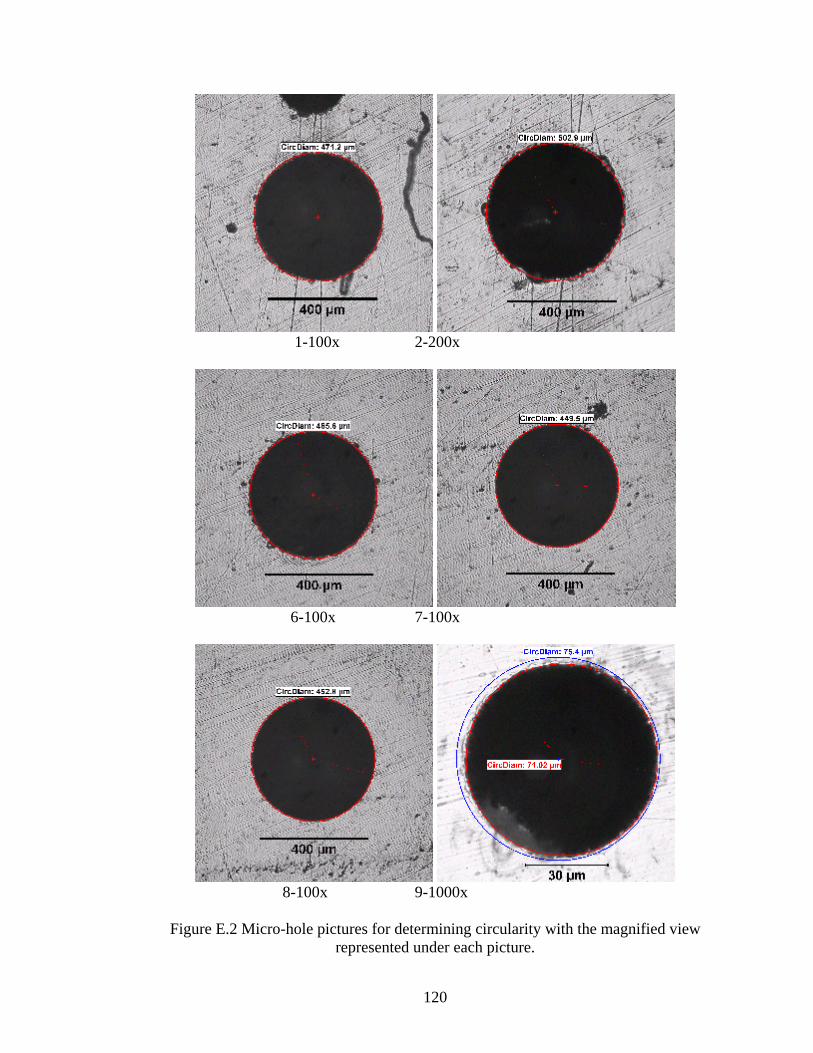
1-100x 2-200x
6-100x 7-100x
8-100x 9-1000x
Figure E.2 Micro-hole pictures for determining circularity with the magnified view represented under each picture.
120
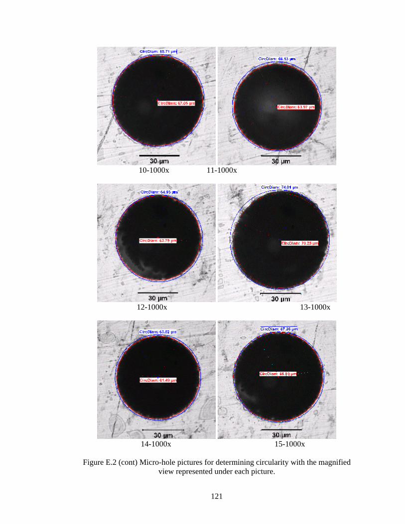
10-1000x 11-1000x
12-1000x 13-1000x
14-1000x 15-1000x
Figure E.2 (cont) Micro-hole pictures for determining circularity with the magnified view represented under each picture.
121

16-1000x 17-500x
Figure E.2 (cont) Micro-hole pictures for determining circularity with the magnified view represented under each picture.
Circularity degree of the machined micro-hole are calculated by considering the most
outer and the most inner diameter difference and. This gives the value of away from full
circle or tendency to the elliptical shape. Table E.3 shows the circularity degree of the
micro-holes with the corresponding tool electrode.
Table E.3 Circularity degree of Micro-holes
Hole-9 Hole-10 Hole-11 Hole-12 Hole-13 Hole-14 Hole-15 Tool diameter 48 35 38 32 47 43 40 Inner diameter 71,02 67,05 63,97 62,79 70,25 61,49 66,03 Outer diameter 75,4 68,71 66,53 64,93 74,01 63,82 67,26 Circularity 2,19 0,83 1,28 1,07 1,88 1,17 0,62
*Dimensions in µm
122