manufacturing processes ( 2), ie-352 ahmed m el...
TRANSCRIPT
Manufacturing Engineering Technology in SI Units, 6th Edition PART IV:
Machining Processes and Machine Tools
Copyright © 2010 Pearson Education South Asia Pte Ltd
Manufacturing Processes (2), IE-352 Ahmed M El-Sherbeeny, PhD
Spring-2016
PART IV: Machining Processes and Machine Tools
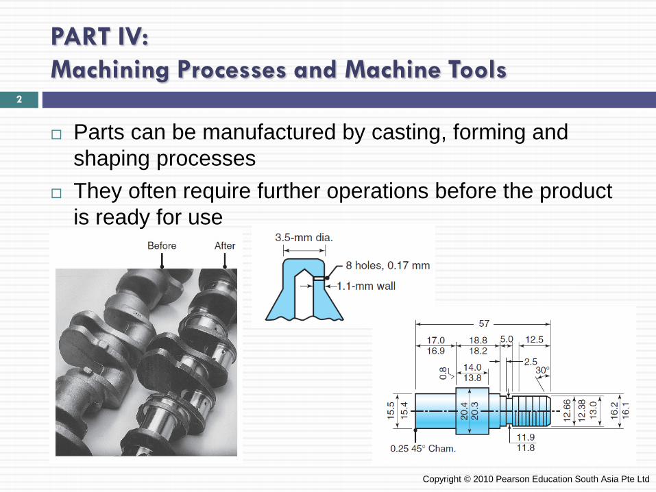
Parts can be manufactured by casting, forming and shaping processes
They often require further operations before the product is ready for use
Copyright © 2010 Pearson Education South Asia Pte Ltd
2
PART IV: Machining Processes and Machine Tools
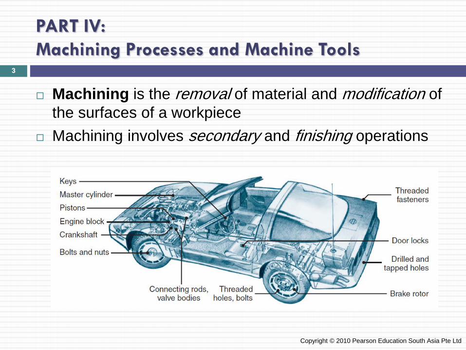
Machining is the removal of material and modification of the surfaces of a workpiece
Machining involves secondary and finishing operations
Copyright © 2010 Pearson Education South Asia Pte Ltd
3
PART IV: Machining Processes and Machine Tools
Major types of material removal processes: 1. Cutting 2. Abrasive processes 3. Advanced machining processes
Machining operations is a system consisting of the 1. Workpiece 2. Cutting tool 3. Machine tool 4. Production personnel
Copyright © 2010 Pearson Education South Asia Pte Ltd
4
Manufacturing Engineering Technology in SI Units, 6th Edition Chapter 21: Fundamentals of Machining
Copyright © 2010 Pearson Education South Asia Pte Ltd Copyright © 2010 Pearson Education South Asia Pte Ltd
5
Chapter Outline
1. Introduction 2. Mechanics of Cutting 3. Cutting Forces and Power 4. Temperatures in Cutting 5. Tool Life: Wear and Failure 6. Surface Finish and Integrity 7. Machinability
Copyright © 2010 Pearson Education South Asia Pte Ltd
6
Introduction
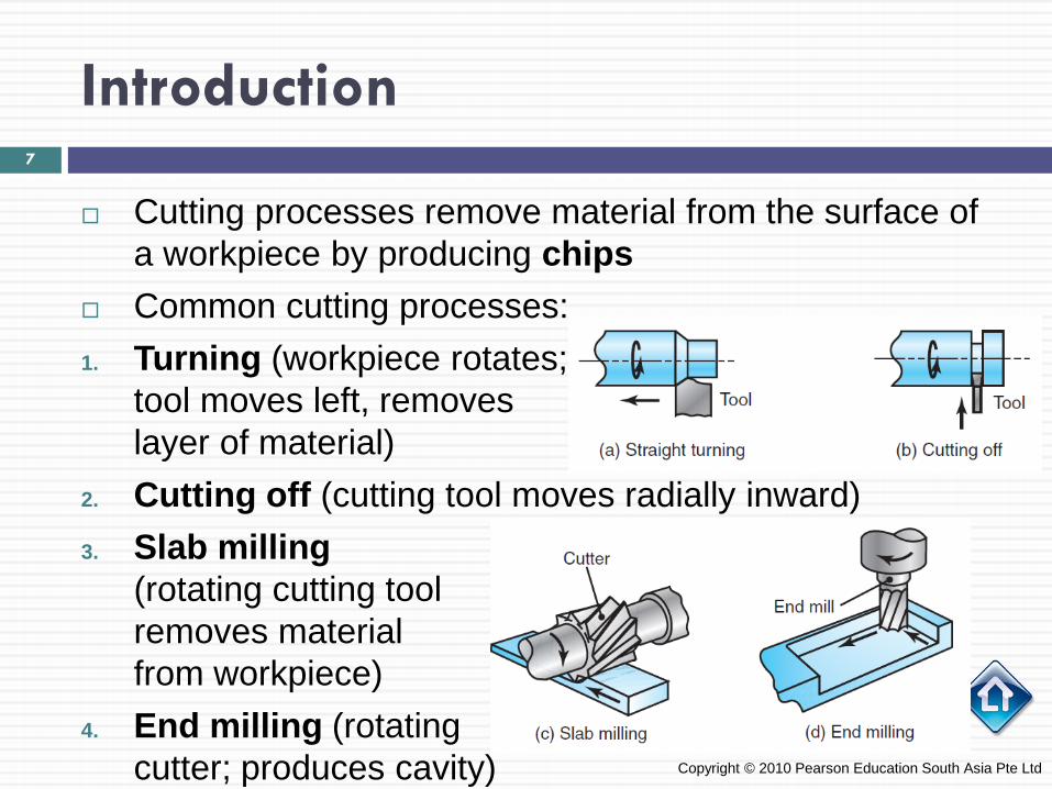
Cutting processes remove material from the surface of a workpiece by producing chips
Common cutting processes: 1. Turning (workpiece rotates;
tool moves left, removes layer of material)
2. Cutting off (cutting tool moves radially inward) 3. Slab milling
(rotating cutting tool removes material from workpiece)
4. End milling (rotating cutter; produces cavity) Copyright © 2010 Pearson Education South Asia Pte Ltd
7

Introduction
In the turning process, the cutting tool is set at a certain depth of cut [mm] and travels to the left (with a certain velocity) as the workpiece rotates
Feed, or feed rate, is the distance the tool travels horizontally per unit revolution of the workpiece [mm/rev]
This tool movement produces chips, which move up the face of the tool
Copyright © 2010 Pearson Education South Asia Pte Ltd
8
Introduction
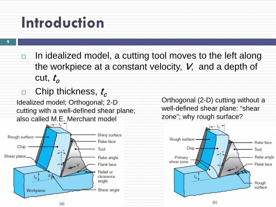
In idealized model, a cutting tool moves to the left along the workpiece at a constant velocity, V, and a depth of cut, to
Chip thickness, tc
Copyright © 2010 Pearson Education South Asia Pte Ltd
Idealized model; Orthogonal; 2-D cutting with a well-defined shear plane; also called M.E. Merchant model
Orthogonal (2-D) cutting without a well-defined shear plane: “shear zone”; why rough surface?
9
Mechanics of Cutting
Copyright © 2010 Pearson Education South Asia Pte Ltd
10
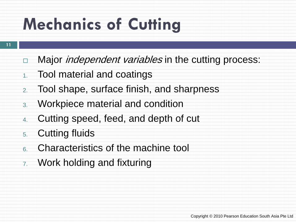
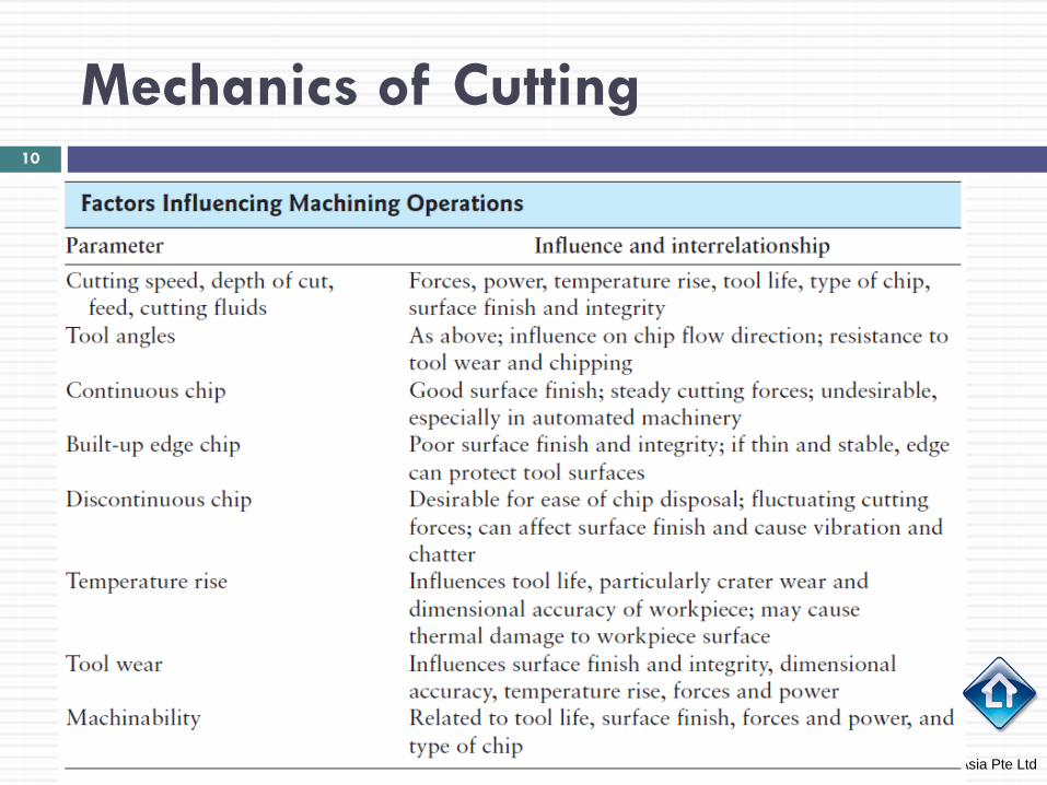
Mechanics of Cutting
Major independent variables in the cutting process: 1. Tool material and coatings 2. Tool shape, surface finish, and sharpness 3. Workpiece material and condition 4. Cutting speed, feed, and depth of cut 5. Cutting fluids 6. Characteristics of the machine tool 7. Work holding and fixturing
Copyright © 2010 Pearson Education South Asia Pte Ltd
11
Mechanics of Cutting
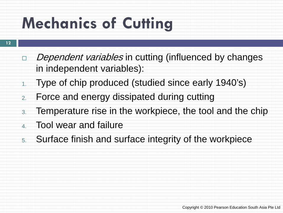
Dependent variables in cutting (influenced by changes in independent variables):
1. Type of chip produced (studied since early 1940’s) 2. Force and energy dissipated during cutting 3. Temperature rise in the workpiece, the tool and the chip 4. Tool wear and failure 5. Surface finish and surface integrity of the workpiece
Copyright © 2010 Pearson Education South Asia Pte Ltd
12
Mechanics of Cutting
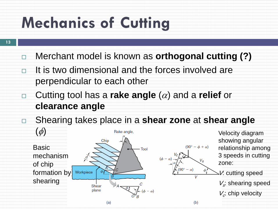
Merchant model is known as orthogonal cutting (?) It is two dimensional and the forces involved are
perpendicular to each other Cutting tool has a rake angle (α) and a relief or
clearance angle Shearing takes place in a shear zone at shear angle
(φ)
Basic mechanism of chip formation by shearing
Velocity diagram showing angular relationship among 3 speeds in cutting zone: V: cutting speed Vs: shearing speed Vc: chip velocity
13
Mechanics of Cutting
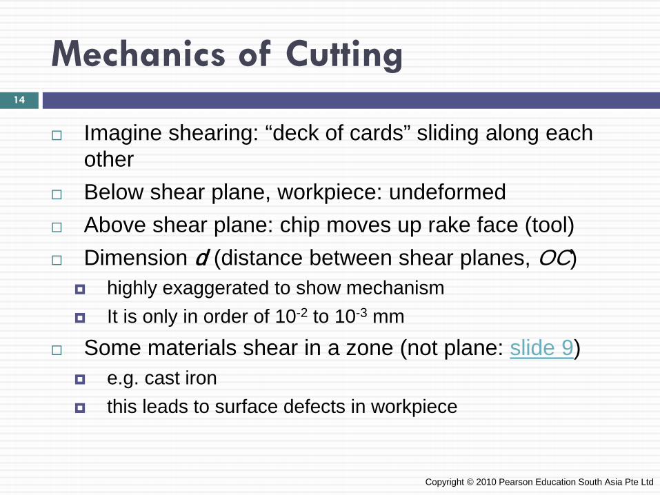
Imagine shearing: “deck of cards” sliding along each other
Below shear plane, workpiece: undeformed Above shear plane: chip moves up rake face (tool) Dimension d (distance between shear planes, OC)
highly exaggerated to show mechanism It is only in order of 10-2 to 10-3 mm
Some materials shear in a zone (not plane: slide 9) e.g. cast iron this leads to surface defects in workpiece
Copyright © 2010 Pearson Education South Asia Pte Ltd
14
Mechanics of Cutting
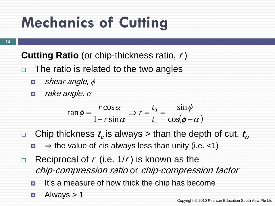
Cutting Ratio (or chip-thickness ratio, r ) The ratio is related to the two angles
shear angle, φ rake angle, α
Chip thickness tc is always > than the depth of cut, to ⇒ the value of r is always less than unity (i.e. <1)
Reciprocal of r (i.e. 1/r ) is known as the chip-compression ratio or chip-compression factor
It’s a measure of how thick the chip has become Always > 1
Copyright © 2010 Pearson Education South Asia Pte Ltd
( )αφφ
ααφ
−==⇒
−=
cossin
sin1costan 0
cttr
rr
15
Mechanics of Cutting
Making use of cutting ratio in evaluating cutting conditions: depth of cut, to: machine setting (i.e. indep. variable) chip thickness, tc can be measured using micrometer cutting ratio, r can then easily be calculated rake angle, α is also known for cutting operation
It is function of tool and workpiece geometry
Cutting ratio and rake angle can be used to find shear angle, φ (equation in previous slide)
Copyright © 2010 Pearson Education South Asia Pte Ltd
16
Mechanics of Cutting
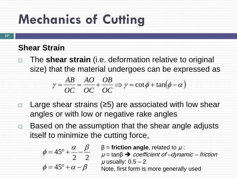
Shear Strain The shear strain (i.e. deformation relative to original
size) that the material undergoes can be expressed as
Large shear strains (≥5) are associated with low shear angles or with low or negative rake angles
Based on the assumption that the shear angle adjusts itself to minimize the cutting force,
( )αφφγγ −+=⇒+== tancotOCOB
OCAO
OCAB
4522
45
βαφ
βαφ
−+°=
−+°=β = friction angle, related to μ : μ = tanβ coefficient of –dynamic – friction μ usually: 0.5 – 2 Note, first form is more generally used
17

Mechanics of Cutting
Chip encounters friction as it moves up the rake face Large variations in contact pressure and temperature
are encountered at the tool-chip interface (rake face) This causes big changes in μ and it is thus called
“apparent mean coefficient of friction” Equation (second set in previous slide) thus indicates:
As rake angle ↓ or friction at rake face ↑ ⇒ shear angle ↓ and chip becomes thicker
Thicker chip ⇒ more energy lost because shear strain is higher
Because work done during cutting is converted into heat ⇒ temperature rise is higher
18
Mechanics of Cutting
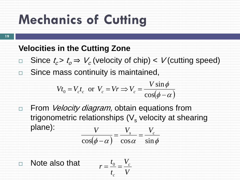
Velocities in the Cutting Zone Since tc > to ⇒ Vc (velocity of chip) < V (cutting speed) Since mass continuity is maintained,
From Velocity diagram, obtain equations from trigonometric relationships (Vs velocity at shearing plane):
Note also that
( )αφφ−
=⇒==cos
sinor 0VVVrVtVVt cccc
( ) φααφ sincoscoscs VVV
==−
VV
ttr c
c
== 0
19
Mechanics of Cutting: Types of Chips Produced in Metal Cutting
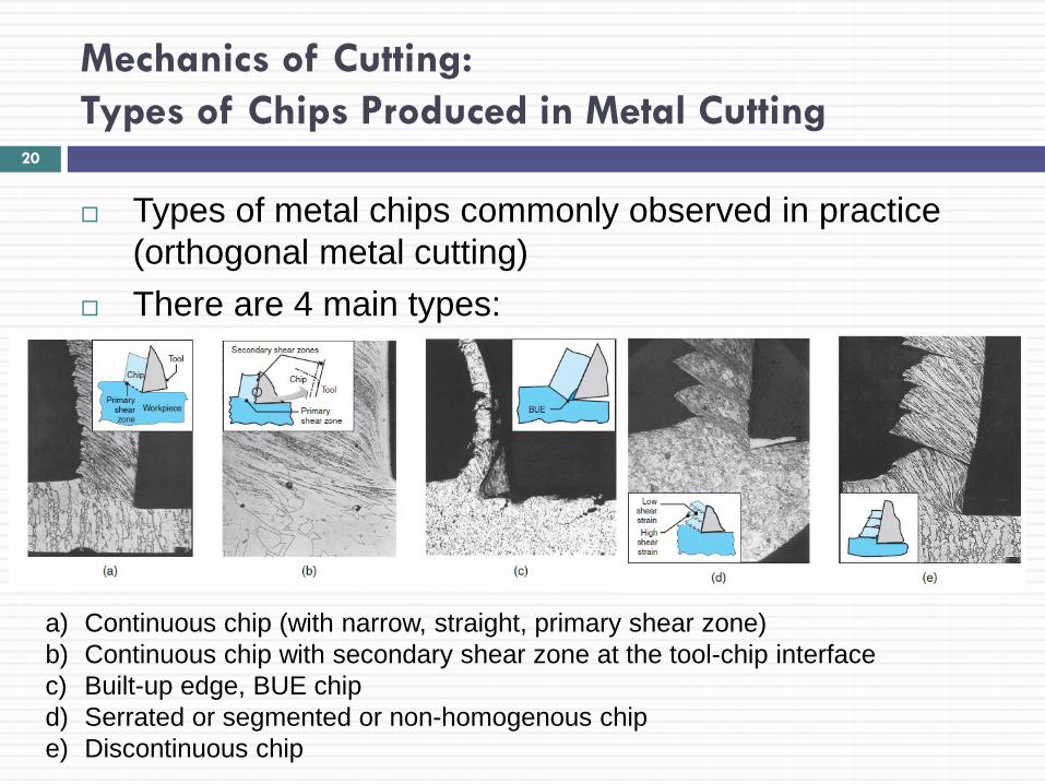
Types of metal chips commonly observed in practice (orthogonal metal cutting)
There are 4 main types:
a) Continuous chip (with narrow, straight, primary shear zone) b) Continuous chip with secondary shear zone at the tool-chip interface c) Built-up edge, BUE chip d) Serrated or segmented or non-homogenous chip e) Discontinuous chip
20
Mechanics of Cutting: Types of Chips Produced in Metal Cutting
All Chips Chip has two surfaces: Surface in contact with rake face
Shiny and polished Caused by rubbing of the chip on the tool surface
Outer surface from the original surface of the workpiece Jagged, rough appearance Caused by shearing mechanism Note, this surface remains exposed to the environment, and
does not come into contact with any other surface
Copyright © 2010 Pearson Education South Asia Pte Ltd
21
Mechanics of Cutting: Types of Chips Produced in Metal Cutting
Continuous Chips Formed with ductile materials machined at high cutting
speeds and/or high rake angles Deformation takes place along a narrow shear zone
called the (primary shear zone) Continuous chips may develop a secondary shear zone
due to high friction at the tool–chip interface This zone becomes thicker as friction increases
Continuous chips may also occur with wide primary shear zone with curved boundaries (slide 9)
Note, lower boundary of deformation zone drops below machined surface ⇒ distortion in workpiece, poor finish
Occurs: machining soft metals at low speeds, low rake angles
22
Mechanics of Cutting: Types of Chips Produced in Metal Cutting
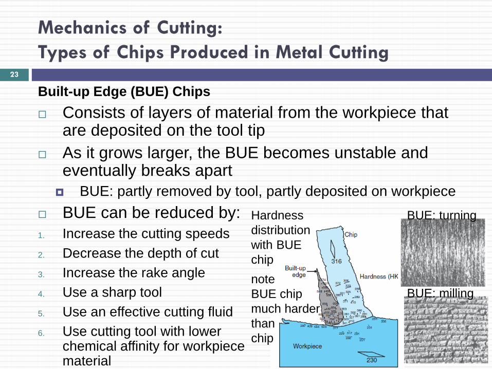
Built-up Edge (BUE) Chips Consists of layers of material from the workpiece that
are deposited on the tool tip As it grows larger, the BUE becomes unstable and
eventually breaks apart BUE: partly removed by tool, partly deposited on workpiece
BUE can be reduced by: 1. Increase the cutting speeds 2. Decrease the depth of cut 3. Increase the rake angle 4. Use a sharp tool 5. Use an effective cutting fluid 6. Use cutting tool with lower
chemical affinity for workpiece material
Hardness distribution with BUE chip note BUE chip much harder than chip
BUE: turning
BUE: milling
23

Mechanics of Cutting: Types of Chips Produced in Metal Cutting
Serrated Chips Also called segmented or nonhomogeneous chips They are semicontinuous chips with
large zones of low shear strain and small zones of high shear strain (shear localization)
Example: metals with low thermal conductivity and strength that decreases sharply with temperature, i.e. thermal softening (e.g. titanium)
Chips have a sawtooth-like appearance Note, do not confuse this with dimension d (slide 13)
Copyright © 2010 Pearson Education South Asia Pte Ltd
24
Mechanics of Cutting: Types of Chips Produced in Metal Cutting
Discontinuous Chips Consist of segments that are attached firmly or loosely
to each other Form under the following conditions: 1. Brittle workpiece materials 2. Materials with hard inclusions and impurities 3. Very low or very high cutting speeds 4. Large depths of cut 5. Low rake angles 6. Lack of an effective cutting fluid 7. Low stiffness of the machine tool (⇒ vibration, chatter)
Copyright © 2010 Pearson Education South Asia Pte Ltd
25
Mechanics of Cutting: Types of Chips Produced in Metal Cutting
Chip Curl Chips will develop a curvature (chip curl) as they leave
the workpiece surface Factors affecting the chip curl conditions are: 1. Distribution of stresses in the primary and secondary
shear zones. 2. Thermal effects. 3. Work-hardening characteristics of the workpiece
material 4. Geometry of the cutting tool 5. Cutting fluids Note, as cutting depth ↓, chip radius ↓ (i.e. curlier)
26
Mechanics of Cutting: Types of Chips Produced in Metal Cutting
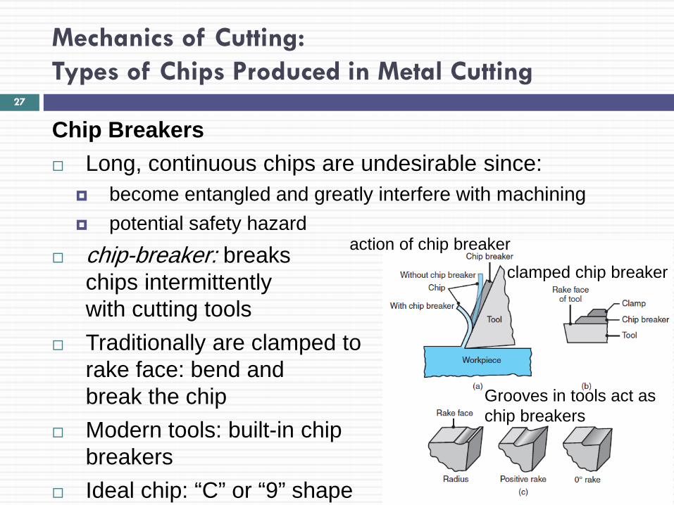
Chip Breakers Long, continuous chips are undesirable since:
become entangled and greatly interfere with machining potential safety hazard
chip-breaker: breaks chips intermittently with cutting tools
Traditionally are clamped to rake face: bend and break the chip
Modern tools: built-in chip breakers
Ideal chip: “C” or “9” shape
clamped chip breaker
Grooves in tools act as chip breakers
27
action of chip breaker
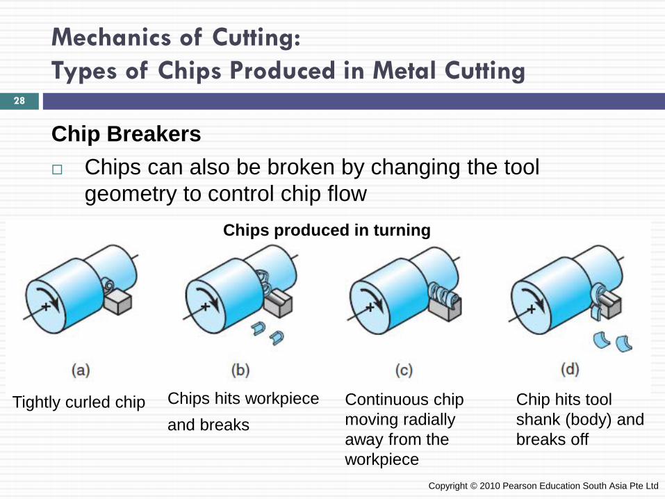
Mechanics of Cutting: Types of Chips Produced in Metal Cutting
Chip Breakers Chips can also be broken by changing the tool
geometry to control chip flow
Copyright © 2010 Pearson Education South Asia Pte Ltd
Tightly curled chip
Chips produced in turning
Chips hits workpiece and breaks
Continuous chip moving radially away from the workpiece
Chip hits tool shank (body) and breaks off
28
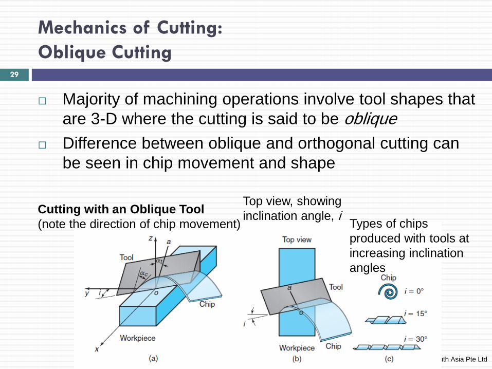
Mechanics of Cutting: Oblique Cutting
Majority of machining operations involve tool shapes that are 3-D where the cutting is said to be oblique
Difference between oblique and orthogonal cutting can be seen in chip movement and shape
Copyright © 2010 Pearson Education South Asia Pte Ltd
29
Cutting with an Oblique Tool (note the direction of chip movement)
Top view, showing inclination angle, i Types of chips
produced with tools at increasing inclination angles
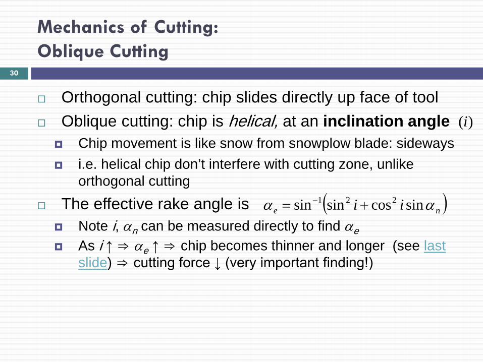
Mechanics of Cutting: Oblique Cutting
Orthogonal cutting: chip slides directly up face of tool Oblique cutting: chip is helical, at an inclination angle
Chip movement is like snow from snowplow blade: sideways i.e. helical chip don’t interfere with cutting zone, unlike
orthogonal cutting
The effective rake angle is Note i, αn can be measured directly to find αe As i ↑ ⇒ αe ↑ ⇒ chip becomes thinner and longer (see last
slide) ⇒ cutting force ↓ (very important finding!)
( )ne ii αα sincossinsin 221 += −
)(i
30
Mechanics of Cutting: Oblique Cutting
Shaving and Skiving Thin layers of material can be removed from straight or
curved surfaces (similar to shaving wood with a plane) Shaving can improve the surface finish and
dimensional accuracy Parts that are long or combination of shapes are
shaved by skiving A specially shaped cutting tool is moved tangentially across
the length of the workpiece
Copyright © 2010 Pearson Education South Asia Pte Ltd
31
Cutting Forces and Power
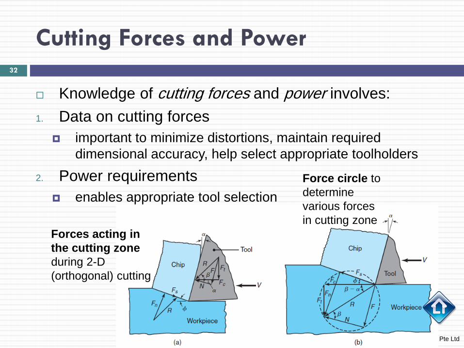
Knowledge of cutting forces and power involves: 1. Data on cutting forces
important to minimize distortions, maintain required dimensional accuracy, help select appropriate toolholders
2. Power requirements enables appropriate tool selection
Copyright © 2010 Pearson Education South Asia Pte Ltd
32
Forces acting in the cutting zone during 2-D (orthogonal) cutting
Force circle to determine various forces in cutting zone
Cutting Forces and Power
Forces considered in orthogonal cutting include Cutting, friction (tool face), and shear forces
Cutting force,Fc acts in the direction of the cutting speed V, and supplies the energy required for cutting
Ratio of Fc to cross-sectional area being cut (i.e. product of width and depth of cut, t0) is called: specific cutting force
Thrust force,Ft acts in a direction normal to the cutting force
These two forces produces the resultant force, R see force circle (last slide)
On tool face, resultant force can be resolved into: Friction force, F along the tool-chip interface Normal force, N to ⊥ to friction force
33

Cutting Forces and Power
It can also be shown that (β is friction angle)
Resultant force, R is balanced by an equal and opposite force along the shear plane
It is resolved into shear force, Fs and normal force, Fn Thus,
The magnitude of coefficient of friction, µ is
Copyright © 2010 Pearson Education South Asia Pte Ltd
ββ cossin RNRF =⇒=
φφφφ
cossinsincos
tcn
tcs
FFFFFF
+=−=
ααµ
tantan
tc
ct
FFFF
NF
−+
==
34
Cutting Forces and Power
Thrust Force The toolholder, work-holding devices, and machine tool
must be stiff to support thrust force with minimal deflections
If Ft is too high ⇒ tool will be pushed away from workpiece this will reduce depth of cut and dimensional accuracy
The effect of rake angle and friction angle on the direction of thrust force is
Magnitude of the cutting force, Fc is always positive as the force that supplies the work is required in cutting
However, Ft can be +ve or –ve; i.e. Ft can be upward with a) high rake angle, b) low tool-chip friction, or c) both
( ) ( )αβαβ −=−= tanor sin ctt FFRF
35
Cutting Forces and Power
Power The power input in cutting is
Power is dissipated in
shear plane/zone (due to energy required to shear material) Rake face (due to tool-chip interface friction)
Power dissipated in shearing is
Denoting the width of cut as w, (i.e. area of cut: wt0), the specific energy for shearing, is
VFPower c=
ssVF=shearingfor Power
VwtVFu ss
s0
=
36
Cutting Forces and Power
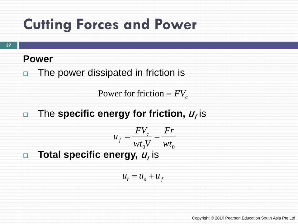
Power The power dissipated in friction is
The specific energy for friction, uf is
Total specific energy, ut is
Copyright © 2010 Pearson Education South Asia Pte Ltd
cFV=frictionfor Power
00 wtFr
VwtFVu c
f ==
fst uuu +=
37
Cutting Forces and Power
Power
Copyright © 2010 Pearson Education South Asia Pte Ltd
38
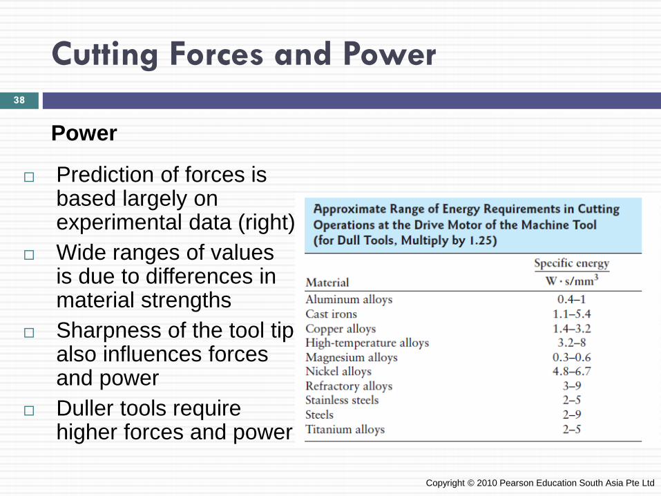
Prediction of forces is based largely on experimental data (right)
Wide ranges of values is due to differences in material strengths
Sharpness of the tool tip also influences forces and power
Duller tools require higher forces and power

Cutting Forces and Power
Measuring Cutting Forces and Power Cutting forces can be measured using a force
transducer, a dynamometer or a load cell mounted on the cutting-tool holder
It is also possible to calculate the cutting force from the power consumption during cutting (provided mechanical efficiency of the tool can be determined)
The specific energy (u, last slide) in cutting can be used to calculate cutting forces
Copyright © 2010 Pearson Education South Asia Pte Ltd
39
Cutting Forces and Power
EXAMPLE 21.1 Relative Energies in Cutting In an orthogonal cutting operation, to=0.13 mm, V=120 m/min, α=10° and the width of cut 6 mm. It is observed that tc=0.23 mm, Fc=500 N and Ft=200 N. Calculate the percentage of the total energy that goes into overcoming friction at the tool–chip interface.
Copyright © 2010 Pearson Education South Asia Pte Ltd
40
Cutting Forces and Power
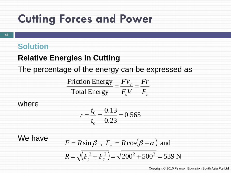
Solution Relative Energies in Cutting The percentage of the energy can be expressed as where We have
Copyright © 2010 Pearson Education South Asia Pte Ltd
cc
c
FFr
VFFV
==Energy Total
EnergyFriction
565.023.013.00 ===
cttr
( )( ) N 539500200
and cos , sin2222 =+=+=
−==
ct
c
FFR
RFRF αββ
41
Cutting Forces and Power
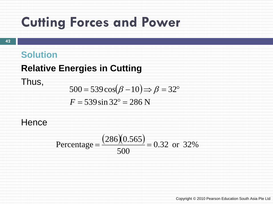
Solution Relative Energies in Cutting Thus, Hence
Copyright © 2010 Pearson Education South Asia Pte Ltd
( )N 28632sin539
3210cos539500=°=
°=⇒−=F
ββ
( )( ) %32or 32.0500
565.0286Percentage ==
42
Temperatures in Cutting
Temperature rise (due to heat lost in cutting ⇒ raising temp. in cutting zone) - its major adverse effects:
1. Lowers the strength, hardness, stiffness and wear resistance of the cutting tool (i.e. alters tool shape)
2. Causes uneven dimensional changes (machined parts) 3. Induce thermal damage and metallurgical changes in
the machined surface (⇒ properties adversely affected) Sources of heat in machining:
a. Work done in shearing (primary shear zone) b. Energy lost due to friction (tool-chip interface) c. Heat generated due to tool rubbing on machined surface
(especially dull or worn tools)
43
Temperatures in Cutting
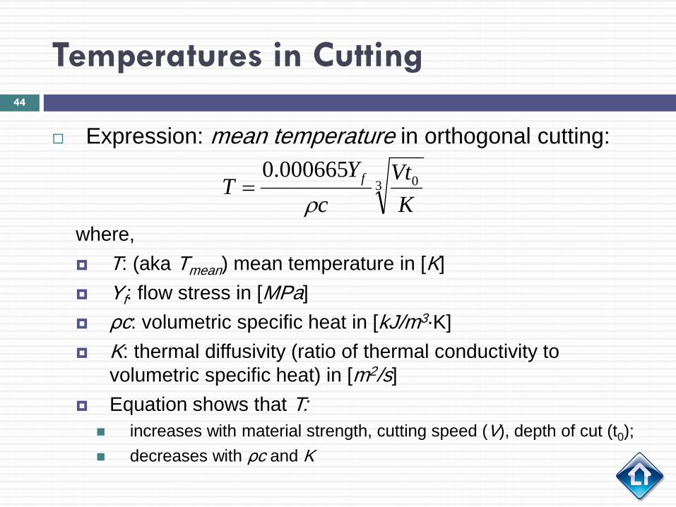
Expression: mean temperature in orthogonal cutting:
where, T: (aka Tmean) mean temperature in [K] Yf: flow stress in [MPa] ρc: volumetric specific heat in [kJ/m3·K] K: thermal diffusivity (ratio of thermal conductivity to
volumetric specific heat) in [m2/s] Equation shows that T: increases with material strength, cutting speed (V), depth of cut (t0); decreases with ρc and K
3 0000665.0K
Vtc
YT f
ρ=
44
Temperatures in Cutting
Mean temperature in turning on a lathe is given by
where, V : cutting speed f : feed of the tool Approximate values of the exponents a,b: Carbide tools: a = 0.2, b = 0.125 High-speed steel tools: a = 0.5, b = 0.375
Also note how this relation shows the increase in temperature with increased cutting speed and feed
bamean fVT ∝
45
Temperatures in Cutting
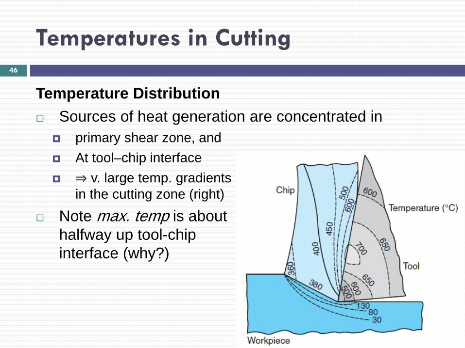
Temperature Distribution Sources of heat generation are concentrated in
primary shear zone, and At tool–chip interface ⇒ v. large temp. gradients
in the cutting zone (right)
Note max. temp is about halfway up tool-chip interface (why?)
46
Temperatures in Cutting
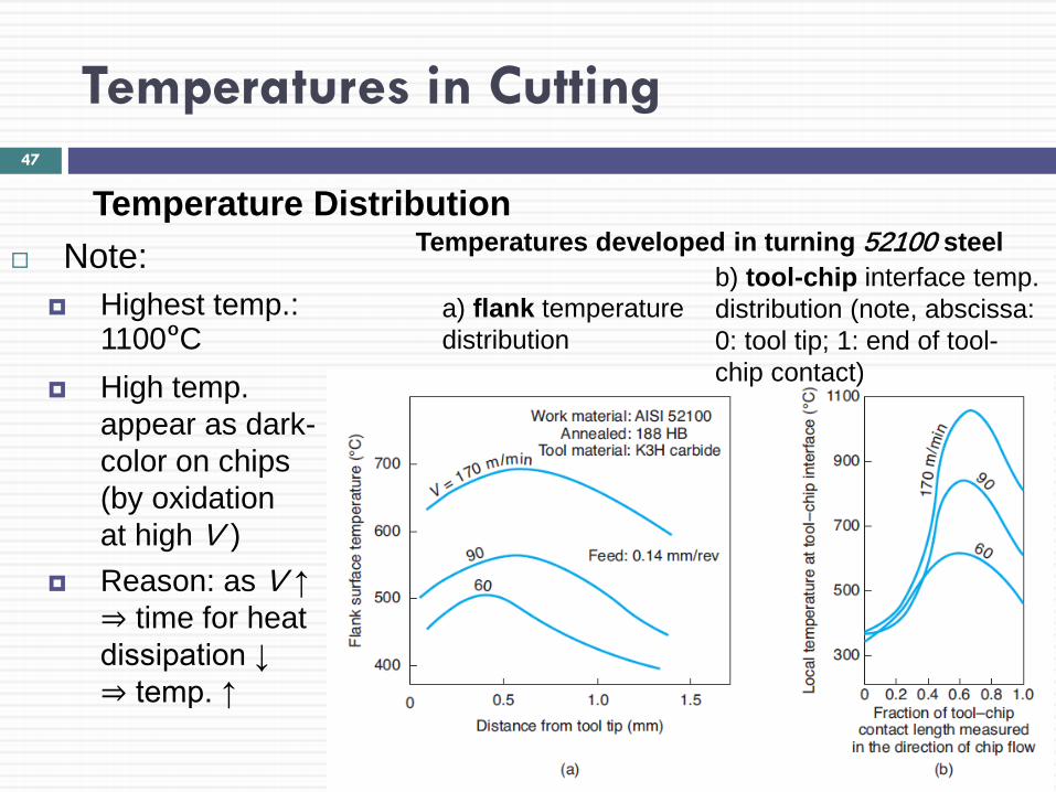
Temperature Distribution Note:
Highest temp.: 1100ºC
High temp. appear as dark- color on chips (by oxidation at high V )
Reason: as V ↑ ⇒ time for heat dissipation ↓ ⇒ temp. ↑
47
a) flank temperature distribution
Temperatures developed in turning 52100 steel b) tool-chip interface temp. distribution (note, abscissa: 0: tool tip; 1: end of tool-chip contact)
Temperatures in Cutting
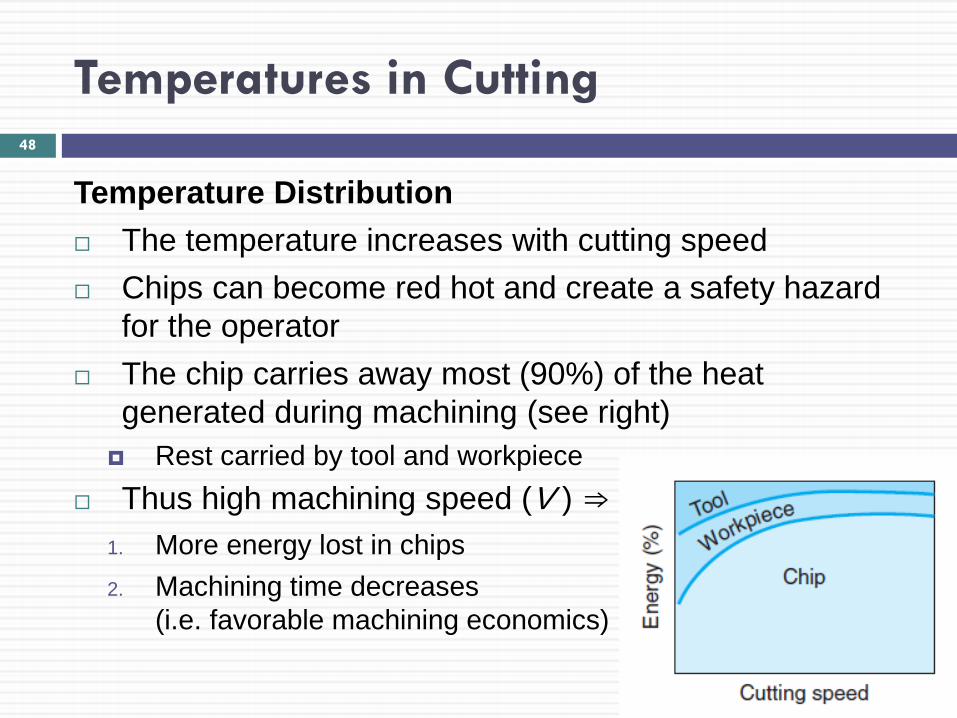
Temperature Distribution The temperature increases with cutting speed Chips can become red hot and create a safety hazard
for the operator The chip carries away most (90%) of the heat
generated during machining (see right) Rest carried by tool and workpiece
Thus high machining speed (V ) ⇒ 1. More energy lost in chips 2. Machining time decreases
(i.e. favorable machining economics)
48
Temperatures in Cutting
Techniques for Measuring Temperature Temperatures and their distribution can be determined
using thermocouples (placed on tool or workpiece) Electromotive force (thermal emf) at the tool-chip interface Measuring infrared radiation (using a radiation pyrometer)
from the cutting zone (only measures surface temperatures)
49
Tool Life: Wear and Failure
Tool wear is gradual process; created due to: 1. High localized stresses at the tip of the tool 2. High temperatures (especially along rake face) 3. Sliding of the chip along the rake face 4. Sliding of the tool along the newly cut workpiece
surface The rate of tool wear depends on
tool and workpiece materials tool geometry process parameters cutting fluids characteristics of the machine tool
Copyright © 2010 Pearson Education South Asia Pte Ltd
50
Tool Life: Wear and Failure
Tool wear and the changes in tool geometry are classified as:
a) Flank wear b) Crater wear c) Nose wear d) Notching e) Plastic deformation of the tool tip f) Chipping and Gross fracture
Copyright © 2010 Pearson Education South Asia Pte Ltd
51

Tool Life: Wear and Failure 52
a) Features of tool wear in a turning operation. VB: indicates average flank wear
b) – e) Examples of wear in cutting tools
b) Flank wear
c) Crater wear
d) Thermal cracking
e) Flank wear and built-up edge (BUE)
Tool Life: Wear and Failure: Flank Wear
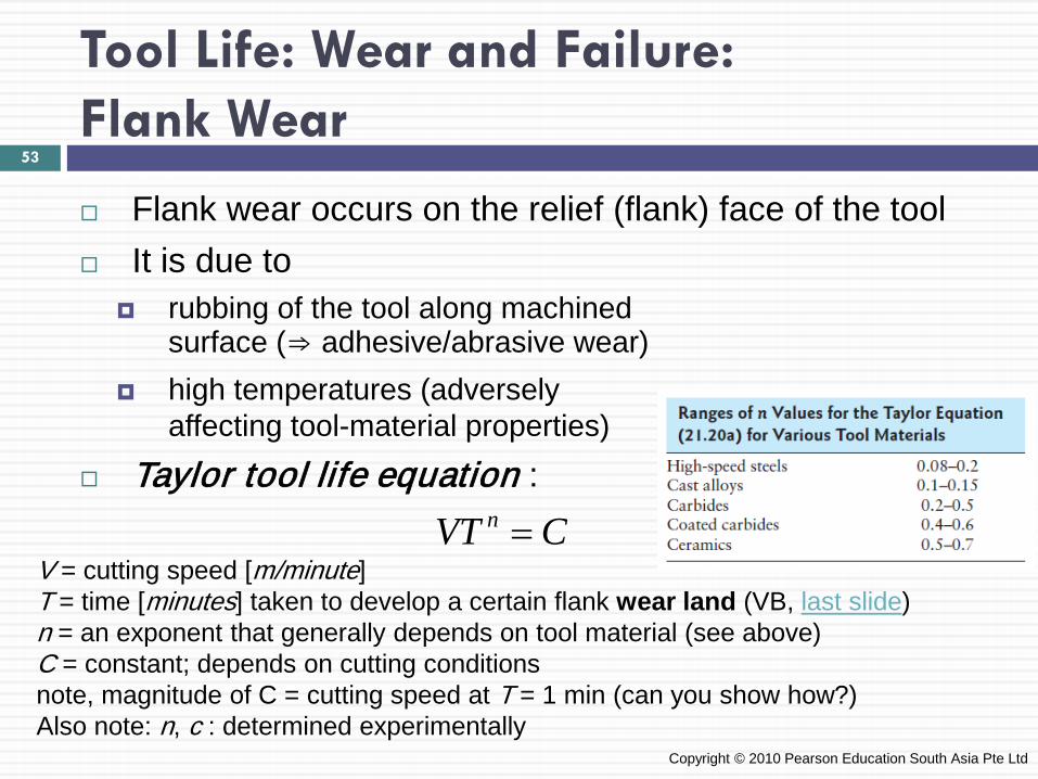
Flank wear occurs on the relief (flank) face of the tool It is due to
rubbing of the tool along machined surface (⇒ adhesive/abrasive wear)
high temperatures (adversely affecting tool-material properties)
Taylor tool life equation :
Copyright © 2010 Pearson Education South Asia Pte Ltd
CVT n =V = cutting speed [m/minute] T = time [minutes] taken to develop a certain flank wear land (VB, last slide) n = an exponent that generally depends on tool material (see above) C = constant; depends on cutting conditions note, magnitude of C = cutting speed at T = 1 min (can you show how?) Also note: n, c : determined experimentally
53
Tool Life: Wear and Failure: Flank Wear
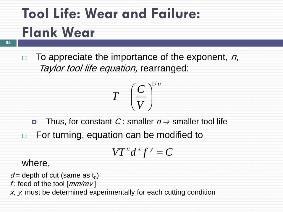
To appreciate the importance of the exponent, n, Taylor tool life equation, rearranged:
Thus, for constant C : smaller n ⇒ smaller tool life
For turning, equation can be modified to
where,
n
VCT
/1
=
54
CfdVT yxn =
d = depth of cut (same as t0) f : feed of the tool [mm/rev ] x, y: must be determined experimentally for each cutting condition
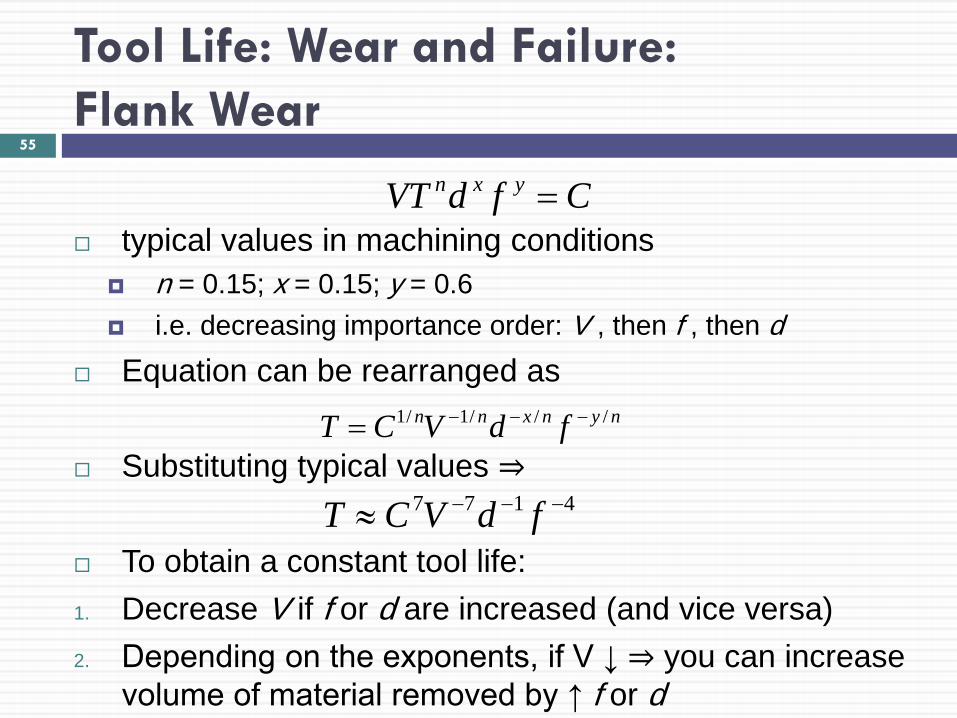
Tool Life: Wear and Failure: Flank Wear
typical values in machining conditions
n = 0.15; x = 0.15; y = 0.6 i.e. decreasing importance order: V , then f , then d
Equation can be rearranged as
Substituting typical values ⇒ To obtain a constant tool life: 1. Decrease V if f or d are increased (and vice versa) 2. Depending on the exponents, if V ↓ ⇒ you can increase
volume of material removed by ↑ f or d
nynxnn fdVCT ///1/1 −−−=
55
CfdVT yxn =
4177 −−−≈ fdVCT
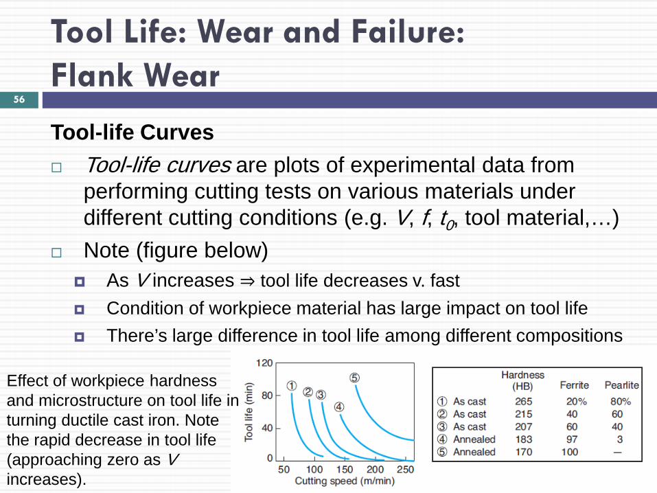
Tool Life: Wear and Failure: Flank Wear
Tool-life Curves Tool-life curves are plots of experimental data from
performing cutting tests on various materials under different cutting conditions (e.g. V, f, t0, tool material,…)
Note (figure below) As V increases ⇒ tool life decreases v. fast Condition of workpiece material has large impact on tool life There’s large difference in tool life among different compositions
56
Effect of workpiece hardness and microstructure on tool life in turning ductile cast iron. Note the rapid decrease in tool life (approaching zero as V increases).
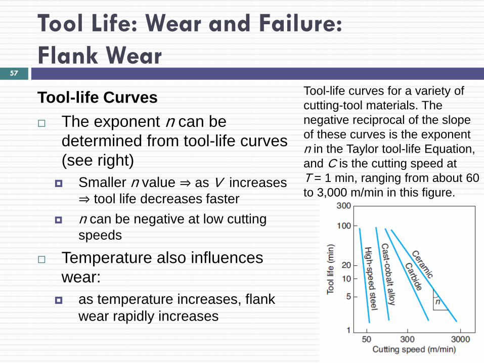
Tool Life: Wear and Failure: Flank Wear
Tool-life Curves The exponent n can be
determined from tool-life curves (see right)
Smaller n value ⇒ as V increases ⇒ tool life decreases faster
n can be negative at low cutting speeds
Temperature also influences wear:
as temperature increases, flank wear rapidly increases
57
Tool-life curves for a variety of cutting-tool materials. The negative reciprocal of the slope of these curves is the exponent n in the Taylor tool-life Equation, and C is the cutting speed at T = 1 min, ranging from about 60 to 3,000 m/min in this figure.
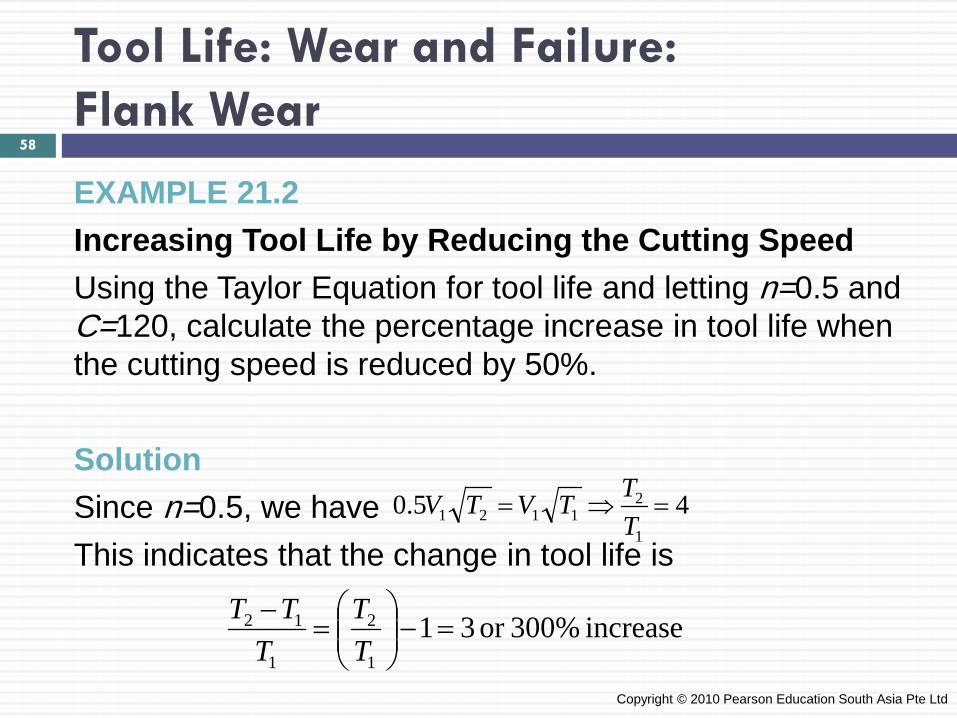
Tool Life: Wear and Failure: Flank Wear
EXAMPLE 21.2 Increasing Tool Life by Reducing the Cutting Speed Using the Taylor Equation for tool life and letting n=0.5 and C=120, calculate the percentage increase in tool life when the cutting speed is reduced by 50%. Solution Since n=0.5, we have This indicates that the change in tool life is
Copyright © 2010 Pearson Education South Asia Pte Ltd
45.01
21121 =⇒=
TTTVTV
increase 300%or 311
2
1
12 =−
=
−TT
TTT
58
Tool Life: Wear and Failure: Flank Wear
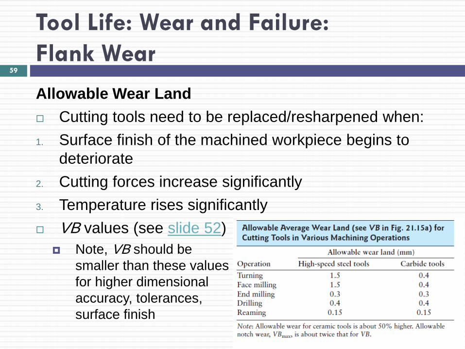
Allowable Wear Land Cutting tools need to be replaced/resharpened when: 1. Surface finish of the machined workpiece begins to
deteriorate 2. Cutting forces increase significantly 3. Temperature rises significantly VB values (see slide 52)
Note, VB should be smaller than these values for higher dimensional accuracy, tolerances, surface finish
59

Tool Life: Wear and Failure: Flank Wear
Allowable Wear Land Recommended cutting speed is one producing tool life:
60-120 min: high-speed steel tools 30-60 min: carbide tools
Note, with pc-controlled machine tools, values can vary significantly from above
Optimum Cutting Speed Optimum cutting speed is a tradeoff between:
1. Cutting speed(V ), since as V ↑, tool life quickly ↓ 2. Material removal rate, since as V ↓, tool life ↑, but material
removal rate also ↓
60
Tool Life: Wear and Failure: Flank Wear
EXAMPLE 21.3 Effect of Cutting Speed on Material Removal When cutting speed is 60 m/min, tool life is 40 min The tool travels a distance of 60 x 40 = 2400 m When cutting speed is increased to 120 m/min, tool life
reduced 5 min and travels 600 m It can be seen that by decreasing the cutting speed,
more material is removed between tool changes
Copyright © 2010 Pearson Education South Asia Pte Ltd
61
Tool Life: Wear and Failure: Crater Wear
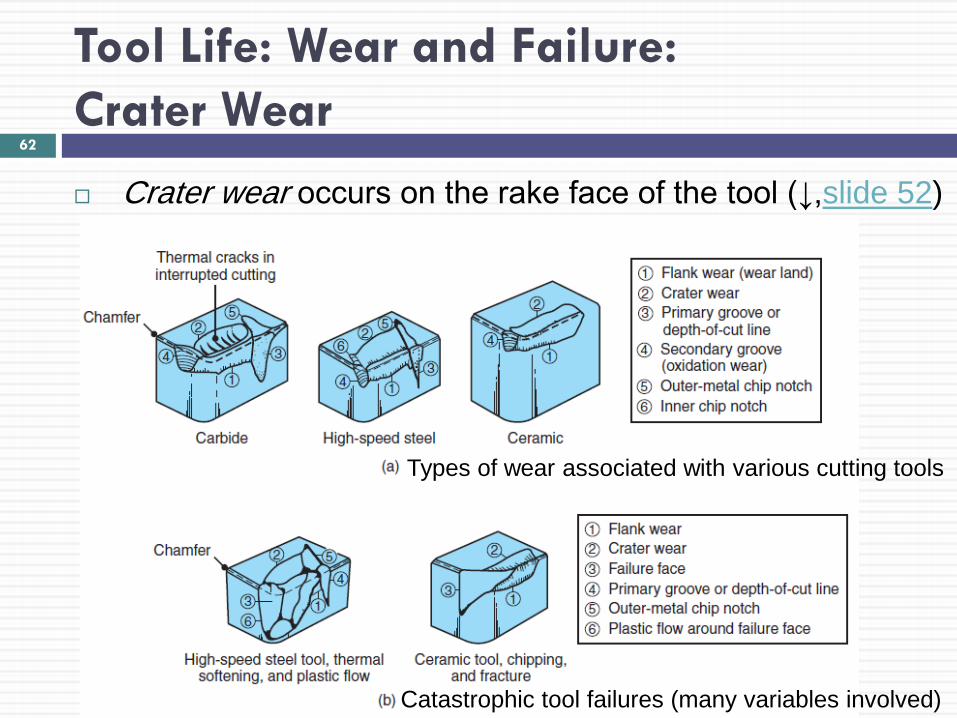
Crater wear occurs on the rake face of the tool (↓,slide 52)
62
Types of wear associated with various cutting tools
Catastrophic tool failures (many variables involved)
Tool Life: Wear and Failure: Crater Wear
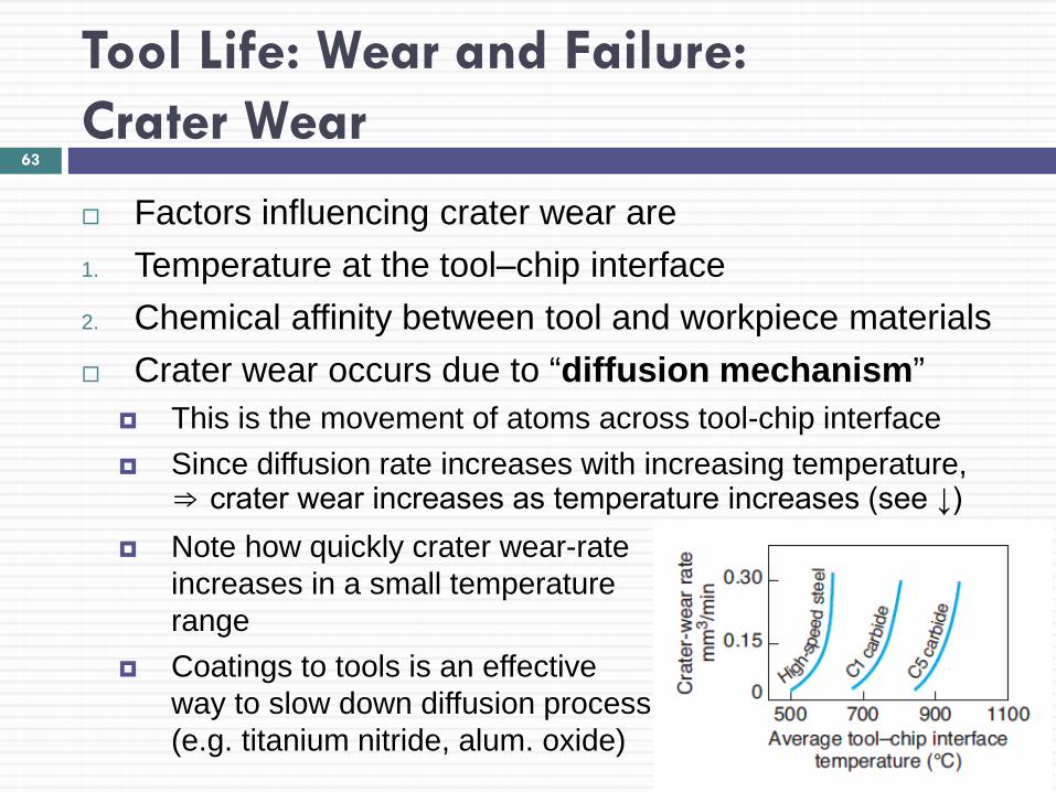
Factors influencing crater wear are 1. Temperature at the tool–chip interface 2. Chemical affinity between tool and workpiece materials Crater wear occurs due to “diffusion mechanism”
This is the movement of atoms across tool-chip interface Since diffusion rate increases with increasing temperature,
⇒ crater wear increases as temperature increases (see ↓) Note how quickly crater wear-rate
increases in a small temperature range
Coatings to tools is an effective way to slow down diffusion process (e.g. titanium nitride, alum. oxide)
63
Tool Life: Wear and Failure: Crater Wear
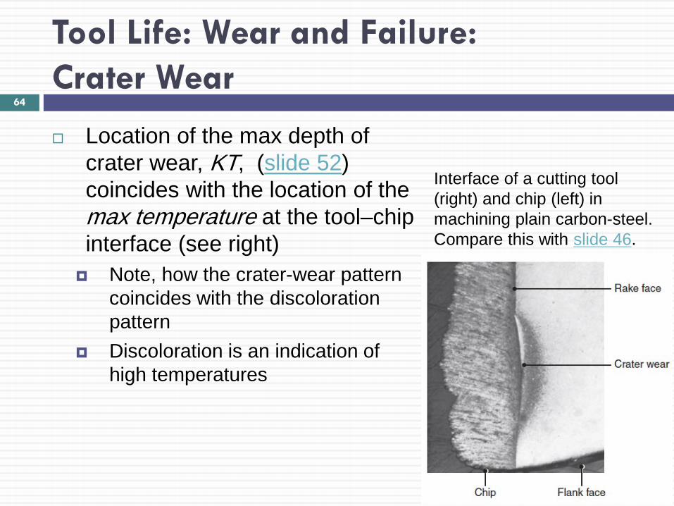
Location of the max depth of crater wear, KT, (slide 52) coincides with the location of the max temperature at the tool–chip interface (see right)
Note, how the crater-wear pattern coincides with the discoloration pattern
Discoloration is an indication of high temperatures
64
Interface of a cutting tool (right) and chip (left) in machining plain carbon-steel. Compare this with slide 46.
Tool Life: Wear and Failure: Other Types of Wear, Chipping, and Fracture
Nose wear (slide 52) is the rounding of a sharp tool due to mechanical and thermal effects
It dulls the tool, affects chip formation, and causes rubbing of the tool over the workpiece
This raises tool temperature, which causes residual stresses on machined surface
Tools also may undergo plastic deformation because of temperature rises in the cutting zone
Temp. may reach 1000 ºC (or higher in stronger materials)
Notches or grooves (slides 52, 62) occur at boundary where chip no longer touches tool
Boundary is called depth- of-cut (DOC) line with depth VN Can lead to gross chipping in tool (due to small area)
65
Tool Life: Wear and Failure: Other Types of Wear, Chipping, and Fracture
Tools may undergo chipping, where small fragment from the cutting edge of the tool breaks away
Mostly occurs with brittle tool materials (e.g. ceramics) Small fragments: “microchipping” or “macrochipping” Large fragments: “gross fracture” or “catastrophic failure”
Chipping may occur in a region of the tool where a small crack already exists
This causes sudden loss of tool material, change in tool shape ⇒ drastic effects on surface finish, dimensional accuracy
Two main causes of chipping Mechanical shock (impact due to interrupted cutting) Thermal fatigue (variations in temp. due to interrupted cutting) Note, thermal cracks are ⊥ to rake face (slide 62)
66
Tool Life: Wear and Failure: Tool-condition Monitoring
It is v. important to continuously monitor the condition of the cutting tool to observe wear, chipping, gross failure
Tool-condition monitoring systems are integrated into computer numerical control (CNC) and programmable logic controllers (PLC)
Classified into 2 categories: 1. Direct method 2. Indirect methods
67
Tool Life: Wear and Failure: Tool-condition Monitoring
1. Direct method for observing the condition of a cutting tool involves optical measurements of wear
e.g. periodic observation of changes in tool using microscope e.g. programming tool to touch a sensor after every machining
cycle (to detect broken tools)
2. Indirect methods of observing tool conditions involve the correlation of the tool condition with certain parameters
Parameters include forces, power, temp. rise, workpiece surface finish, vibration, chatter
e.g. transducers which correlate acoustic emissions (from stress waves in cutting) to tool wear and chipping
e.g. transducers which continually monitor torque and forces during cutting, plus measure and compensate for tool wear
e.g. sensors which measure temperature during machining
68
Surface Finish and Integrity
Surface finish: this influences the dimensional accuracy of machined parts, as
well as properties and performance in service this refers to geometric features of a surface
Surface integrity this refers to material properties e.g. fatigue life, corrosion resistance this is greatly affected by the nature of the surface produced
The following discussion pertains to showing the different factors that affect surface finish and surface integrity
69
Surface Finish and Integrity
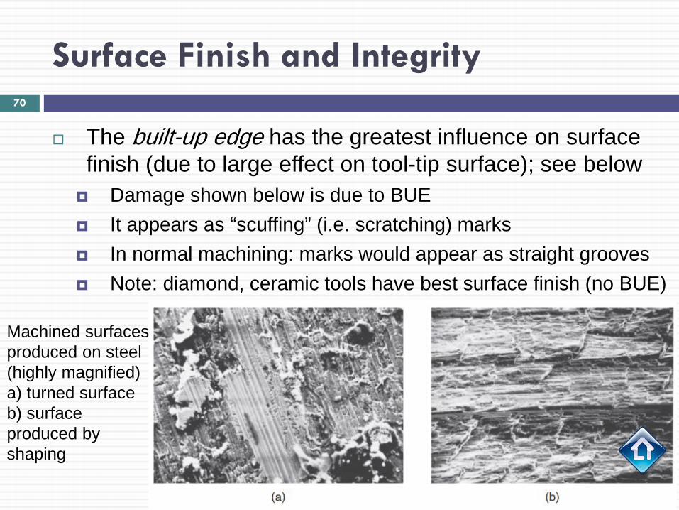
The built-up edge has the greatest influence on surface finish (due to large effect on tool-tip surface); see below
Damage shown below is due to BUE It appears as “scuffing” (i.e. scratching) marks In normal machining: marks would appear as straight grooves Note: diamond, ceramic tools have best surface finish (no BUE)
70
Machined surfaces produced on steel (highly magnified) a) turned surface b) surface produced by shaping
Surface Finish and Integrity
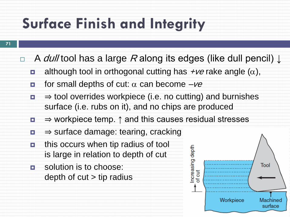
A dull tool has a large R along its edges (like dull pencil) ↓ although tool in orthogonal cutting has +ve rake angle (α), for small depths of cut: α can become –ve ⇒ tool overrides workpiece (i.e. no cutting) and burnishes
surface (i.e. rubs on it), and no chips are produced ⇒ workpiece temp. ↑ and this causes residual stresses ⇒ surface damage: tearing, cracking this occurs when tip radius of tool
is large in relation to depth of cut solution is to choose:
depth of cut > tip radius
71
Surface Finish and Integrity
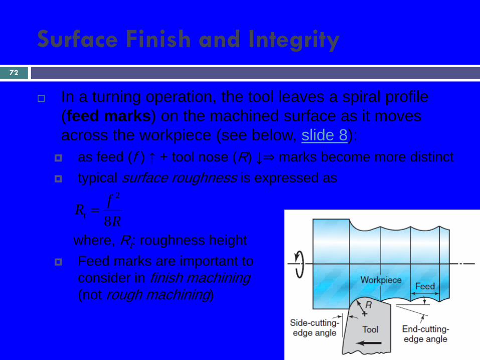
In a turning operation, the tool leaves a spiral profile (feed marks) on the machined surface as it moves across the workpiece (see below, slide 8):
as feed (f ) ↑ + tool nose (R) ↓⇒ marks become more distinct typical surface roughness is expressed as
where, Rt: roughness height Feed marks are important to
consider in finish machining (not rough machining)
RfRt 8
2
=
72
Surface Finish and Integrity
Vibration and chatter adversely affects workpiece surface finish tool vibration ⇒ variations in cutting dimensions chatter ⇒ chipping, premature failure in brittle tools (e.g.
ceramics, diamond)
Factors influencing surface integrity (adversely) are: 1. Temperatures generated during processing 2. Surface residual stresses 3. Severe plastic deformation and strain hardening of the
machined surfaces, tearing and cracking note, each of these factors can be controlled by carefully
choosing and maintaining cutting tools
73
Surface Finish and Integrity
Rough machining vs. Finish machining Rough machining
focus: removing a large amount of material at a high rate surface finish is not emphasized since it will be improved
during finish machining
Finish machining focus is on the surface finish to be produced note, it is important that workpiece has developed no
subsurface-damage due to rough machining (as in slide 70)
74
Machinability
Machinability is defined in terms of: 1. Surface finish and surface integrity of machined part 2. Tool life 3. Force and power required 4. The level of difficulty in chip control Good machinability indicates
good surface finish and surface integrity a long tool life and low force and power requirements
Note, continuous chips should be avoided (slide 22) for good machinability
75
Machinability
Machinability ratings (indexes) these have been used also to determine machinability available for each type of material and its condition not used much anymore due to misleading nature e.g.: AISI 1112 steel with a rating of 100:
for a tool life of 60 min, choose 30 m/min cutting speed (for machining this material)
these are mostly qualitative aspects ⇒ not sufficient to guide operator to machining parts economically
Other guides for various materials should include: cutting speed, feed, depth of cut, cutting tools and shape, cutting fluids
76
Machinability here discussed for the following: Ferrous Metals (e.g. steels, stainless steels, cast iron, etc.) Nonferrous Metals (e.g. aluminum, copper, magnesium) Miscellaneous Materials (e.g. thermoplastics, ceramics) Thermally assisted machining
Machinability of Ferrous Metals: Steels Carbon steels have a wide range of machinability
If a carbon steel is too ductile, chip formation can produce built-up edge, leading to poor surface finish
If too hard, it can cause abrasive wear of the tool because of the presence of carbides in the steel
Cold-worked carbon steels: preferred machinability
Copyright © 2010 Pearson Education South Asia Pte Ltd
77
Machinability
Machinability: Machinability of Ferrous Metals
Steels (cont) Free-machining steels: contain sulfur + phosphorus
Sulfur forms: manganese sulfide inclusions Important to choose size, shape, distribution of inclusions These act as stress raisers in primary shear zone ⇒ chips are small, break easily (i.e. machinability ↑) Phosphorus has two major –desirable– effects 1. Strengthens ferrite ⇒ better chip formation, surface finish ↑ 2. Increases hardness ⇒ short (non-continuous chips) Note, soft steels have low machinability since have tendency
to form BUE ⇒ poor surface finish
Copyright © 2010 Pearson Education South Asia Pte Ltd
78
Machinability: Machinability of Ferrous Metals
Steels (cont) Leaded steels (e.g. 10L45 steel)
high percentage of lead solidifies at the tips of manganese sulfide inclusions
Lead acts as a solid lubricant (due to low shear strength) at tool-chip interface during cutting
It also acts: liquid lubricant when temp. is high in front of tool It also ↓ shear stress at primary shear zone ⇒ ↓ forces and ↓
power consumption Lead is, however, dangerous environmental toxin ⇒ there’s
trend to eliminate use of lead in steel: “lead-free steels” Good substitutes: bismuth, tin (but performance is lower)
Copyright © 2010 Pearson Education South Asia Pte Ltd
79
Machinability: Machinability of Ferrous Metals
Steels (cont) Calcium-deoxidized steels
they contain oxide flakes of calcium silicates (CaSO) these reduce the strength of the secondary shear zone they also decrease tool–chip interface friction and wear ⇒ temp. increases are lower ⇒ less crater wear (why?)
Alloy steels They have a large variety of compositions and hardnesses ⇒ machinability can’t be generalized but they have higher hardness and other properties Can be used to produce good surface finish, integrity,
dimensional accuracy Copyright © 2010 Pearson Education South Asia Pte Ltd
80
Machinability: Machinability of Ferrous Metals
Effects of Various Elements in Steels Presence of aluminum and silicon is harmful in steels
Reason: combine with oxygen to form aluminum oxide and silicates, which are hard and abrasive
⇒ tool wear increases and machinability is reduced
Note that as machinability↑, other properties may ↓ e.g. lead causes embrittlement of steel at high temp.
(although has no effect at room temp.) e.g. sulfur can reduce hot workability of steel
Copyright © 2010 Pearson Education South Asia Pte Ltd
81
Machinability: Machinability of Ferrous Metals
Stainless Steels Austenitic (300 series) steels are difficult to machine
(needs machine tool with high stiffness to avoid chatter) Ferritic stainless steels (also 300 series) have good
machinability Martensitic (400 series) steels are abrasive, tend to form
BUE Precipitation-hardening stainless steels: strong and
abrasive, ⇒ require hard, abrasion-resistant tool Cast Irons Gray irons: machinable, but abrasive (esp. pearlite) Nodular, malleable irons: machinable with hard materials
82
Machinability: Machinability of Nonferrous Metals
Aluminum very easy to machine but softer grades: form BUE ⇒ poor surface finish ⇒ recommend high cutting speeds, high rake and relief angles
Beryllium requires machining in a controlled environment this is due to toxicity of fine particles produced in machining
Cobalt-based alloys abrasive and work hardening require sharp, abrasion-resistant tool materials, and low feeds
and speeds
Copper can be difficult to machine because of BUE formation
83
Machinability: Machinability of Nonferrous Metals
Magnesium very easy to machine, good surface finish, prolonged tool life Caution: high rate of oxidation and fire danger
Titanium and its alloys have very poor thermal conductivity ⇒ high temp. rise and BUE ⇒ difficult to machine
Tungsten brittle, strong, and very abrasive ⇒ machinability is low
Zirconium Good machinability Requires cooling cutting fluid (danger of explosion, fire)
84
Machinability: Machinability of Miscellaneous Materials
Thermoplastics Machining requires sharp tools with positive rake angles, large
relief angles, small depths of cut and feed and high speeds Cooling also required to keep chips from sticking to tools
Polymer-matrix composites: Very abrasive ⇒ difficult to machine Also, requires careful handling; avoid touching, inhaling fibers
Metal-matrix and ceramic-matrix composites can be difficult to machine depending on the properties of the
matrix material and the reinforcing fibers
Graphite Abrasive Requires sharp, hard, abrasion-resistant tools
85

Machinability: Machinability of Miscellaneous Materials
Ceramics Have steadily improving machinability (e.g. nanoceramics) Require appropriate processing parameters
Wood Properties vary with grain direction ⇒ type of chips and surfaces vary significantly depending on
the type of wood and its condition Basic requirements: sharp tools, high cutting speeds
86

Machinability: Thermally Assisted Machining
Metals and alloys that are hard to machine at room temp. can be machined at higher temp.
Thermally assisted machining (hot machining) a source of heat is focused onto an area just ahead of the
cutting tool (e.g. steels hot machined at 650º-750º) e.g. of heat source: torch, electric current, laser-beam Generally difficult and complicated to perform in plants
Advantages of hot machining are: 1. Reduced cutting forces 2. Increased tool life 3. Higher material-removal rates 4. Reduced tendency for vibration and chatter
87