manufacturing processes –...
TRANSCRIPT

Module 2
Mechanics of Machining (Metal
Cutting)
Version 2 ME IIT, Kharagpur
Lesson 3
Geometry of single point cutting tools
Version 2 ME IIT, Kharagpur
Instructional objectives At the end of this lesson, the student should be able to : (a) conceive rake angle and clearance angle of cutting tools (b) classify systems of description of tool geometry (c) demonstrate tool geometry and define tool angles in :
• Machine Reference System • Orthogonal Rake System and • Normal Rake System
(d) designate cutting tool geometry in ASA, ORS and NRS Geometry of single point turning tools Both material and geometry of the cutting tools play very important roles on their performances in achieving effectiveness, efficiency and overall economy of machining. Cutting tools may be classified according to the number of major cutting edges (points) involved as follows:
• Single point: e.g., turning tools, shaping, planning and slotting tools and boring tools
• Double (two) point: e.g., drills • Multipoint (more than two): e.g., milling cutters, broaching tools, hobs,
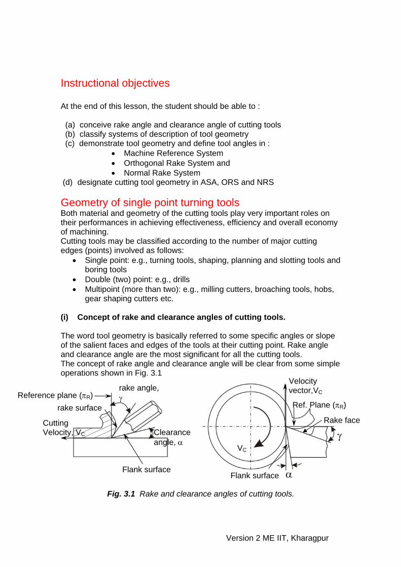
gear shaping cutters etc. (i) Concept of rake and clearance angles of cutting tools. The word tool geometry is basically referred to some specific angles or slope of the salient faces and edges of the tools at their cutting point. Rake angle and clearance angle are the most significant for all the cutting tools. The concept of rake angle and clearance angle will be clear from some simple operations shown in Fig. 3.1
rake angle, γ
Clearance angle, α
Flank surface
rake surface Reference plane (πR)
Cutting Velocity, VC
Flank surface α
γ
Velocity vector,VC
Ref. Plane (πR)
VC
Rake face
Fig. 3.1 Rake and clearance angles of cutting tools.
Version 2 ME IIT, Kharagpur
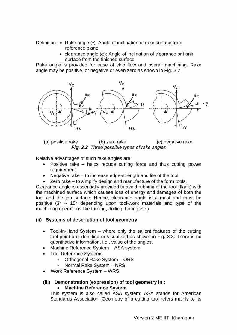
Definition - • Rake angle (γ): Angle of inclination of rake surface from reference plane • clearance angle (α): Angle of inclination of clearance or flank surface from the finished surface Rake angle is provided for ease of chip flow and overall machining. Rake angle may be positive, or negative or even zero as shown in Fig. 3.2.
+γ
+α +α +α
- γ γ=0
VC
VC VC
VC
VC
πR πR πR
(a) positive rake (b) zero rake (c) negative rake
Fig. 3.2 Three possible types of rake angles
Relative advantages of such rake angles are: • Positive rake – helps reduce cutting force and thus cutting power
requirement. • Negative rake – to increase edge-strength and life of the tool • Zero rake – to simplify design and manufacture of the form tools.
Clearance angle is essentially provided to avoid rubbing of the tool (flank) with the machined surface which causes loss of energy and damages of both the tool and the job surface. Hence, clearance angle is a must and must be positive (3o ~ 15o depending upon tool-work materials and type of the machining operations like turning, drilling, boring etc.) (ii) Systems of description of tool geometry
• Tool-in-Hand System – where only the salient features of the cutting tool point are identified or visualized as shown in Fig. 3.3. There is no quantitative information, i.e., value of the angles.
• Machine Reference System – ASA system • Tool Reference Systems
∗ Orthogonal Rake System – ORS ∗ Normal Rake System – NRS
• Work Reference System – WRS (iii) Demonstration (expression) of tool geometry in :
• Machine Reference System This system is also called ASA system; ASA stands for American Standards Association. Geometry of a cutting tool refers mainly to its
Version 2 ME IIT, Kharagpur
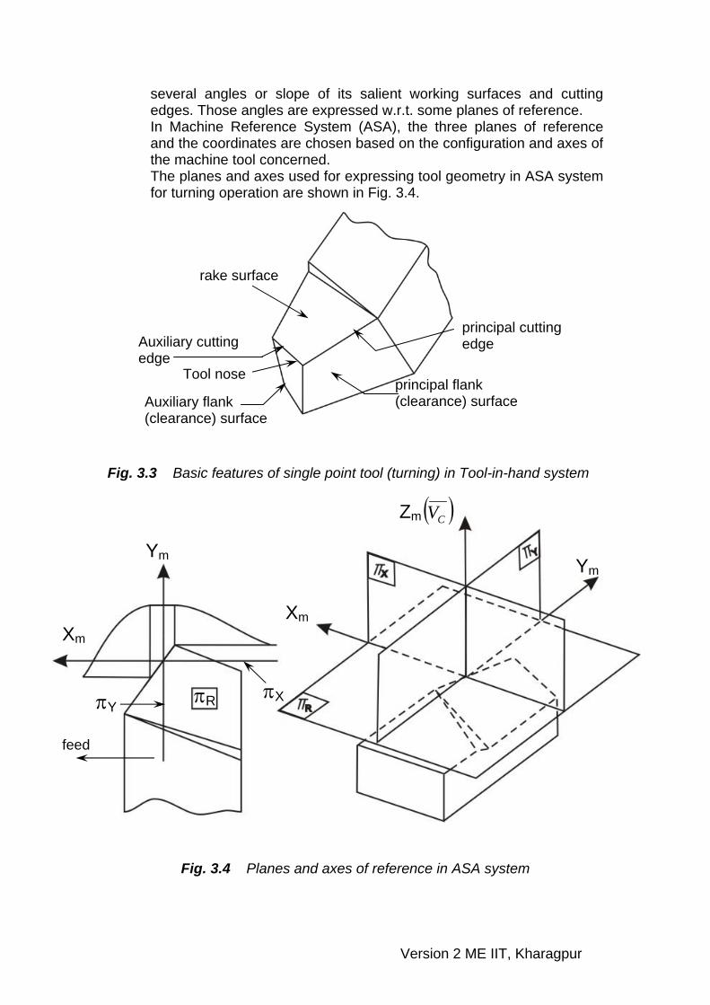
several angles or slope of its salient working surfaces and cutting edges. Those angles are expressed w.r.t. some planes of reference. In Machine Reference System (ASA), the three planes of reference and the coordinates are chosen based on the configuration and axes of the machine tool concerned. The planes and axes used for expressing tool geometry in ASA system for turning operation are shown in Fig. 3.4.
rake surface
Auxiliary cutting edge
Tool nose
Auxiliary flank (clearance) surface
principal cutting edge
principal flank (clearance) surface
Fig. 3.3 Basic features of single point tool (turning) in Tool-in-hand system
feed
πR πXπY
Ym
Xm
Ym
Xm
Zm ( )CV
Fig. 3.4 Planes and axes of reference in ASA system
Version 2 ME IIT, Kharagpur
The planes of reference and the coordinates used in ASA system for tool geometry are :
πR - πX - πY and Xm – Ym - Zmwhere,
πR = Reference plane; plane perpendicular to the velocity vector (shown in Fig. 3.4) πX = Machine longitudinal plane; plane perpendicular to πR and taken in the direction of assumed longitudinal feed πY = Machine Transverse plane; plane perpendicular to both πR and πX [This plane is taken in the direction of assumed cross feed]
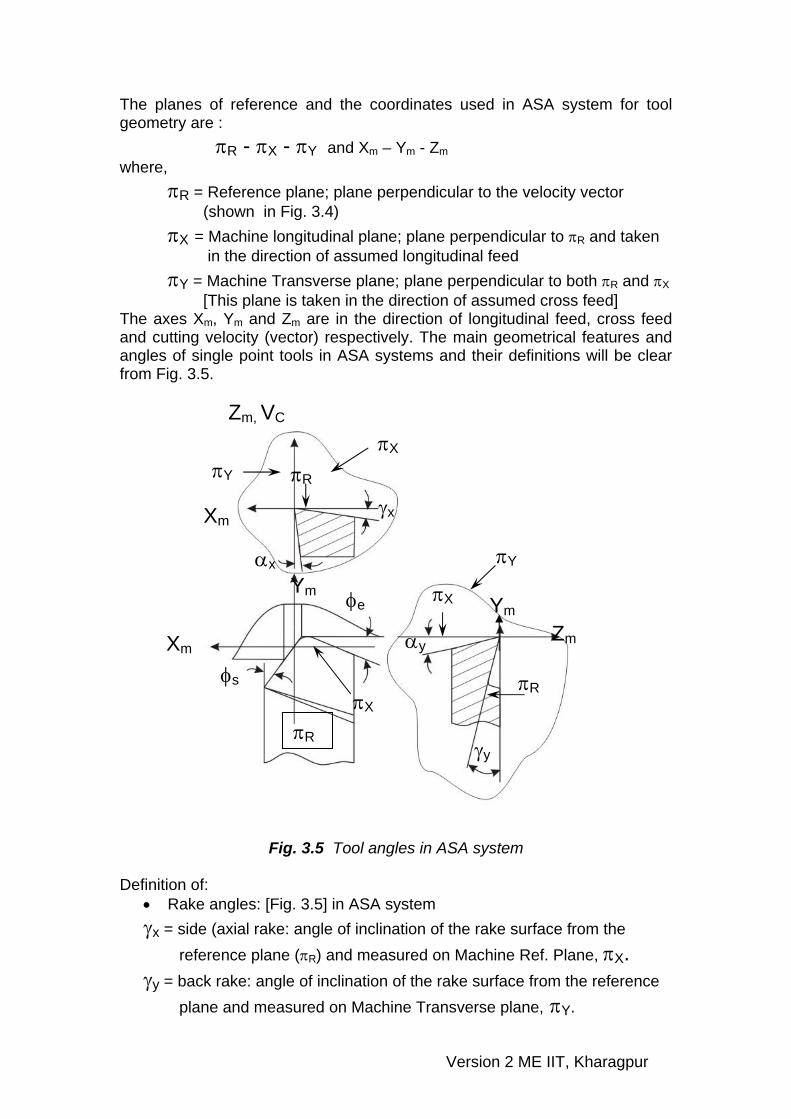
The axes Xm, Ym and Zm are in the direction of longitudinal feed, cross feed and cutting velocity (vector) respectively. The main geometrical features and angles of single point tools in ASA systems and their definitions will be clear from Fig. 3.5.
Zm, VC
Zm
Ym
Xm
πY
πX
πR
πX
γy
φs
φe
αy
αx
πX
πY
Ym
Xm
πR
πR
γx
Fig. 3.5 Tool angles in ASA system
Definition of:
• Rake angles: [Fig. 3.5] in ASA system γx = side (axial rake: angle of inclination of the rake surface from the reference plane (πR) and measured on Machine Ref. Plane, πX. γy = back rake: angle of inclination of the rake surface from the reference plane and measured on Machine Transverse plane, πY.
Version 2 ME IIT, Kharagpur
• Clearance angles: [Fig. 3.5] αx = side clearance: angle of inclination of the principal flank from the machined surface (or CV ) and measured on πX plane.
αy = back clearance: same as αx but measured on πY plane. • Cutting angles: [Fig. 3.5] φs = approach angle: angle between the principal cutting edge (its projection on πR) and πY and measured on πR
φe = end cutting edge angle: angle between the end cutting edge (its projection on πR) from πX and measured on πR• Nose radius, r (in inch) r = nose radius : curvature of the tool tip. It provides strengthening of the tool nose and better surface finish.
• Tool Reference Systems • Orthogonal Rake System – ORS
This system is also known as ISO – old. The planes of reference and the co-ordinate axes used for expressing the tool angles in ORS are:
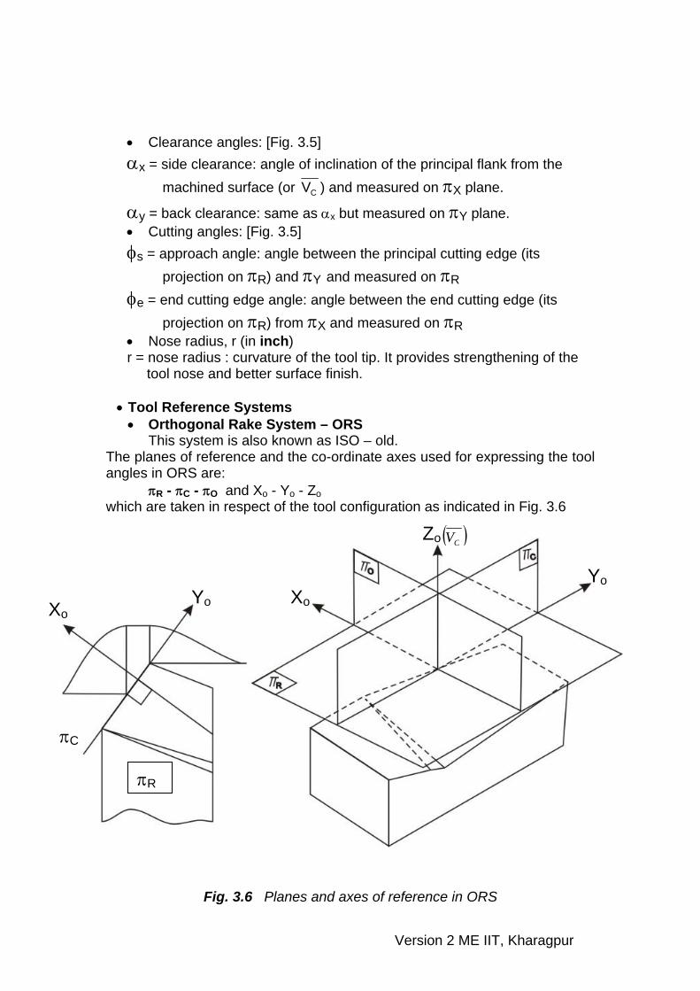
πR - πC - πO and Xo - Yo - Zowhich are taken in respect of the tool configuration as indicated in Fig. 3.6
πR
πC
YoXoXo
Yo
Zo ( )CV
Fig. 3.6 Planes and axes of reference in ORS
Version 2 ME IIT, Kharagpur
where,
πR = Refernce plane perpendicular to the cutting velocity vector, CV
πC = cutting plane; plane perpendicular to πR and taken along the principal cutting edge πO = Orthogonal plane; plane perpendicular to both πR and πC
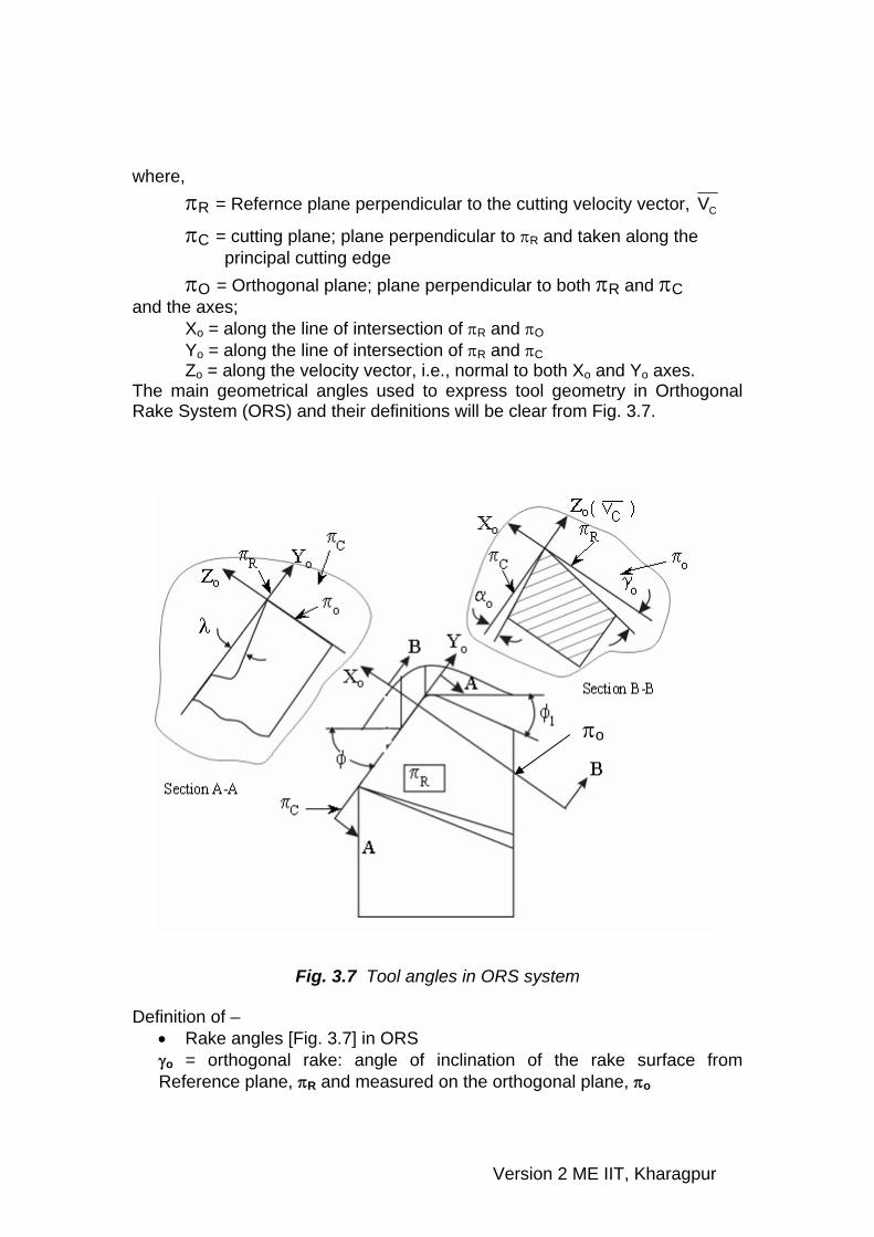
and the axes; Xo = along the line of intersection of πR and πO Yo = along the line of intersection of πR and πC Zo = along the velocity vector, i.e., normal to both Xo and Yo axes. The main geometrical angles used to express tool geometry in Orthogonal Rake System (ORS) and their definitions will be clear from Fig. 3.7.
πo πo
Fig. 3.7 Tool angles in ORS system Definition of –
• Rake angles [Fig. 3.7] in ORS γo = orthogonal rake: angle of inclination of the rake surface from Reference plane, πR and measured on the orthogonal plane, πo
Version 2 ME IIT, Kharagpur
λ = inclination angle; angle between πC from the direction of assumed longitudinal feed [πX] and measured on πC
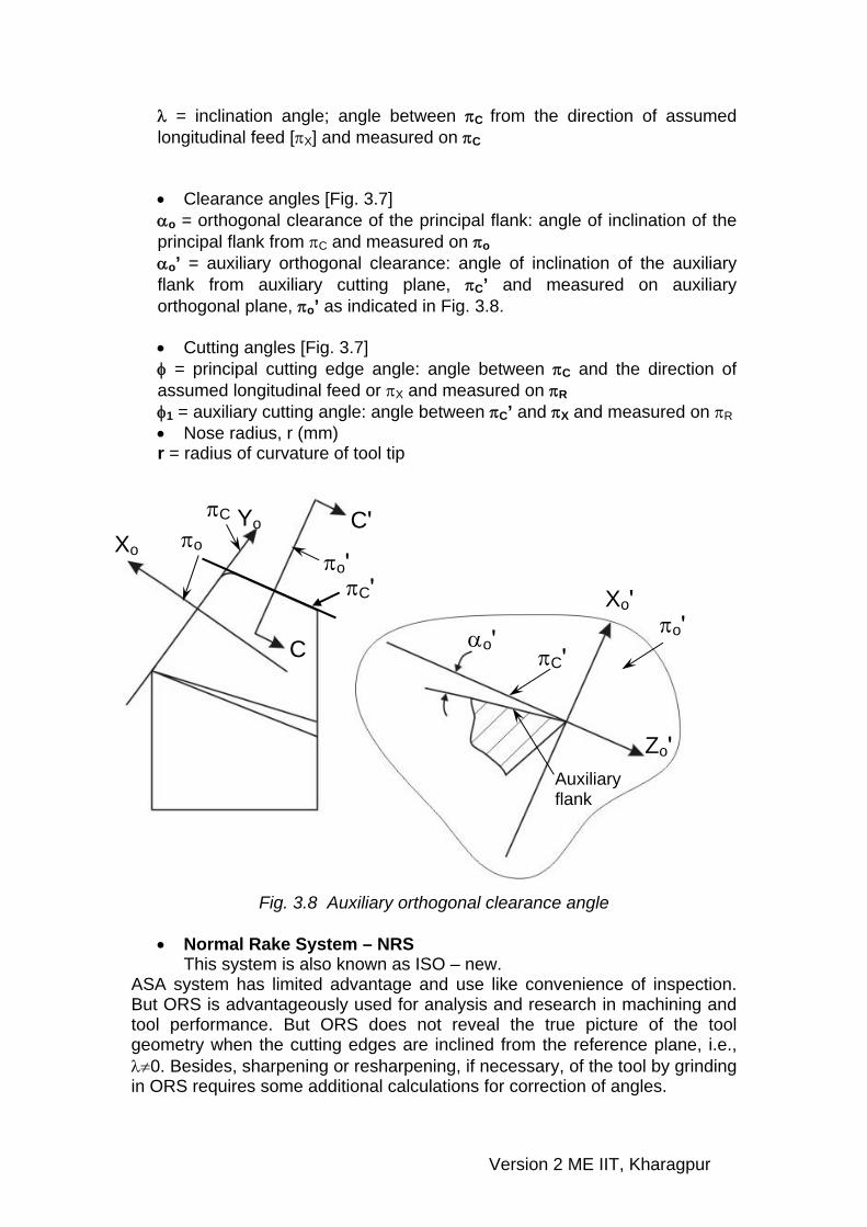
• Clearance angles [Fig. 3.7] αo = orthogonal clearance of the principal flank: angle of inclination of the principal flank from πC and measured on πoαo’ = auxiliary orthogonal clearance: angle of inclination of the auxiliary flank from auxiliary cutting plane, πC’ and measured on auxiliary orthogonal plane, πo’ as indicated in Fig. 3.8.
• Cutting angles [Fig. 3.7] φ = principal cutting edge angle: angle between πC and the direction of assumed longitudinal feed or πX and measured on πRφ1 = auxiliary cutting angle: angle between πC’ and πX and measured on πR• Nose radius, r (mm) r = radius of curvature of tool tip
αo'
Auxiliary flank
Zo'
πC'πo'
πo'
C'
C
YoXo πo
πC
πC' Xo'
Fig. 3.8 Auxiliary orthogonal clearance angle
• Normal Rake System – NRS This system is also known as ISO – new.
ASA system has limited advantage and use like convenience of inspection. But ORS is advantageously used for analysis and research in machining and tool performance. But ORS does not reveal the true picture of the tool geometry when the cutting edges are inclined from the reference plane, i.e., λ≠0. Besides, sharpening or resharpening, if necessary, of the tool by grinding in ORS requires some additional calculations for correction of angles.
Version 2 ME IIT, Kharagpur
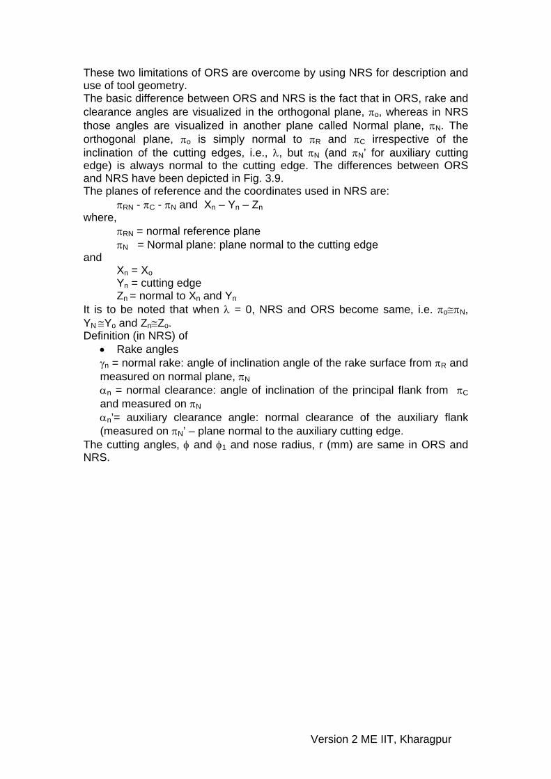
These two limitations of ORS are overcome by using NRS for description and use of tool geometry. The basic difference between ORS and NRS is the fact that in ORS, rake and clearance angles are visualized in the orthogonal plane, πo, whereas in NRS those angles are visualized in another plane called Normal plane, πN. The orthogonal plane, πo is simply normal to πR and πC irrespective of the inclination of the cutting edges, i.e., λ, but πN (and πN’ for auxiliary cutting edge) is always normal to the cutting edge. The differences between ORS and NRS have been depicted in Fig. 3.9. The planes of reference and the coordinates used in NRS are: πRN - πC - πN and Xn – Yn – Zn where, πRN = normal reference plane πN = Normal plane: plane normal to the cutting edge and Xn = Xo Yn = cutting edge Zn = normal to Xn and YnIt is to be noted that when λ = 0, NRS and ORS become same, i.e. πo≅πN, YN ≅Yo and Zn≅Zo. Definition (in NRS) of
• Rake angles γn = normal rake: angle of inclination angle of the rake surface from πR and measured on normal plane, πNαn = normal clearance: angle of inclination of the principal flank from πC and measured on πNαn’= auxiliary clearance angle: normal clearance of the auxiliary flank (measured on πN’ – plane normal to the auxiliary cutting edge.
The cutting angles, φ and φ1 and nose radius, r (mm) are same in ORS and NRS.
Version 2 ME IIT, Kharagpur
Yn
Zn
αn
γn
αo γo
YoZo πo (A-A)
πn (B-B)
A A
B
B
πR πC
λ
γn
γo
Zπn o Zn
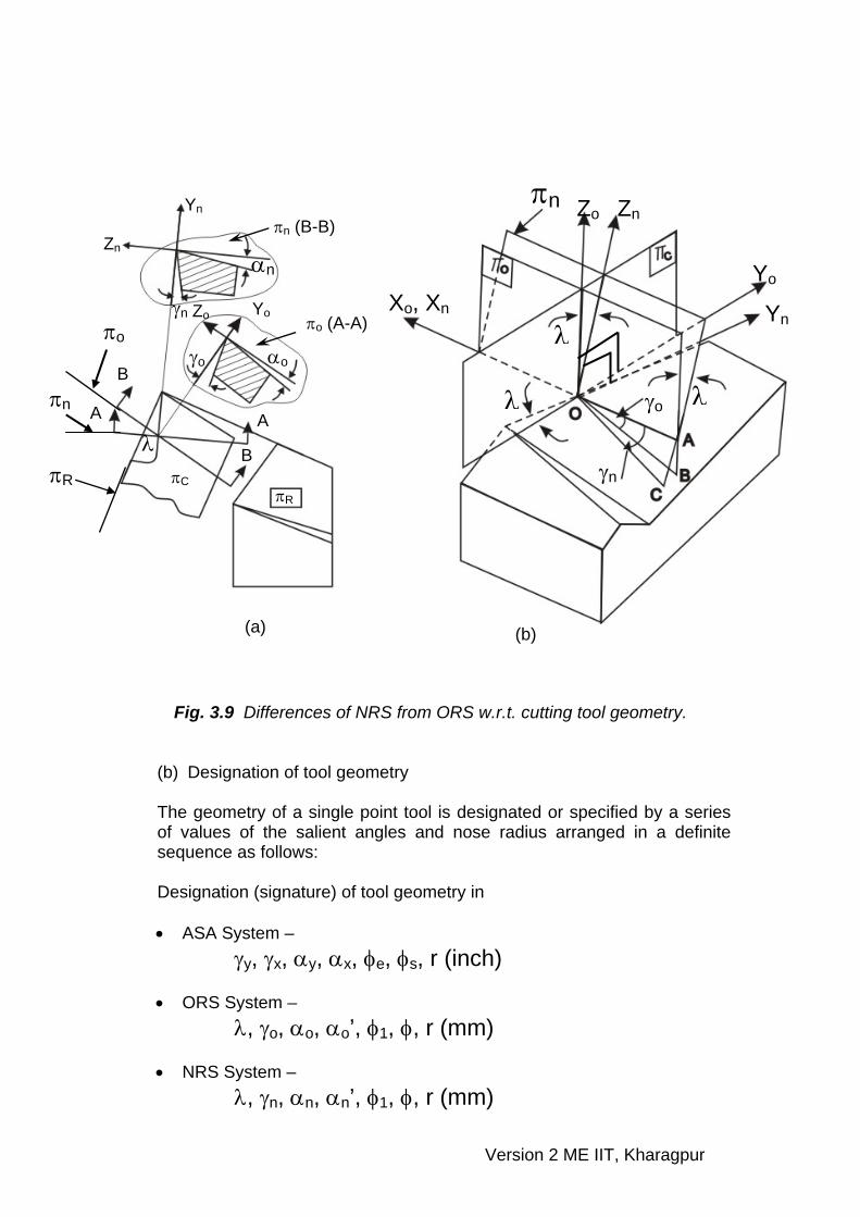
Fig. 3.9 Differences of NRS from ORS w.r.t. cutting tool geometry.
(b) Designation of tool geometry The geometry of a single point tool is designated or specified by a series of values of the salient angles and nose radius arranged in a definite sequence as follows: Designation (signature) of tool geometry in • ASA System –
γy, γx, αy, αx, φe, φs, r (inch)
• ORS System – λ, γo, αo, αo’, φ1, φ, r (mm)
• NRS System –
λ, γn, αn, αn’, φ1, φ, r (mm)
λ
λXo, Xn
(a) (b)
Yo
Ynπo
πn
πR
λ
Version 2 ME IIT, Kharagpur
Exercise – 3 Quiz Test: Select the correct answer from the given four options : 1. Back rake of a turning tool is measured on its
(a) machine longitudinal plane (b) machine transverse plane (c) orthogonal plane (d) normal plane
2. Normal rake and orthogonal rake of a turning tool will be same when its
(a) φ = 0 (b) φ1 = 0 (c) λ = 0 (d) φ1 = 90o
3. Normal plane of a turning tool is always perpendicular to its
(a) πX plane (b) πY plane (c) πC plane (d) none of them
4. Principal cutting edge angle of any turning tool is measured on its
(a) πR (b) πY (c) πX (d) πo
5. A cutting tool can never have its
(a) rake angle – positive (b) rake angle – negative (c) clearance angle – positive (d) clearance angle – negative
6. Orthogonal clearance and side clearance of a turning tool will be same if its perpendicular cutting edge angle is
(a) φ = 30o (b) φ = 45o (c) φ = 60o (d) φ = 90o
Version 2 ME IIT, Kharagpur

7. Inclination angle of a turning tool is measured on its
(a) reference plane (b) cutting plane (c) orthogonal plane (d) normal plane
8. Normal rake and side rake of a turning tool will be same if its
(a) φ = 0o and λ = 0o (b) φ = 90o and λ = 0o (c) φ = 90o and λ = 90o (d) φ = 0o and λ = 90o
Answer of the objective questions 1 – (b) 2 – (c) 3 – (c) 4 – (a) 5 – (d) 6 – (d) 7 – (b) 8 – (b)
Version 2 ME IIT, Kharagpur