mapping textures guilford county sci vis v204.01
TRANSCRIPT
Mapping Textures
Guilford County Sci VisV204.01
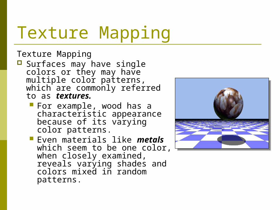
Texture MappingTexture Mapping Surfaces may have single colors
or they may have multiple color patterns, which are commonly referred to as textures. For example, wood has a
characteristic appearance because of its varying color patterns.
Even materials like metals which seem to be one color, when closely examined, reveals varying shades and colors mixed in random patterns.
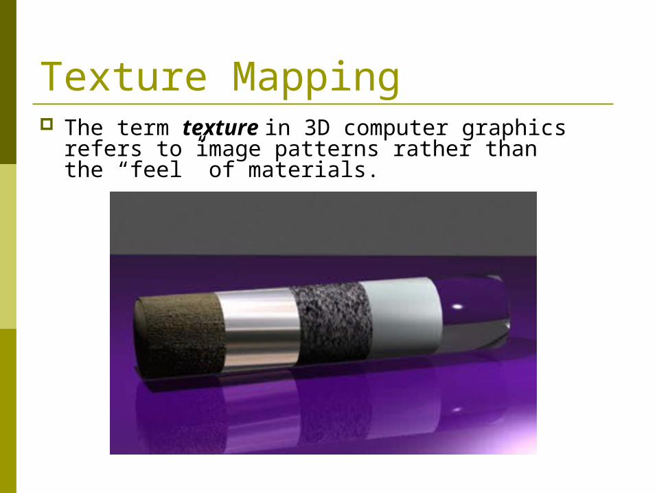
Texture Mapping The term texture in 3D computer graphics
refers to image patterns rather than the “feel” of materials.
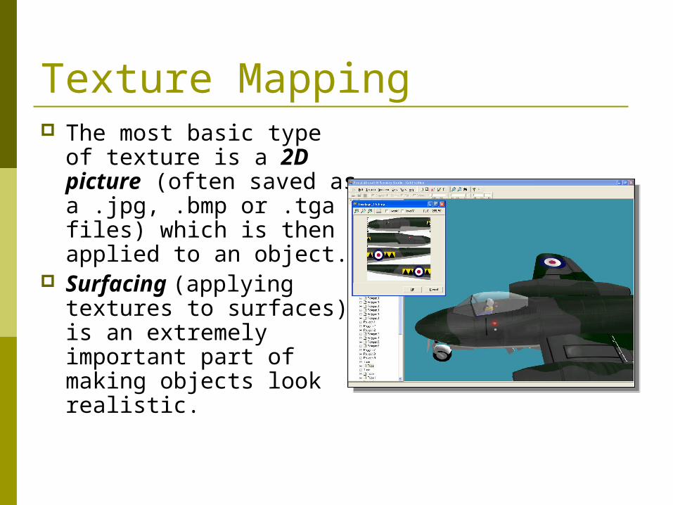
The most basic type of texture is a 2D picture (often saved as a .jpg, .bmp or .tga files) which is then applied to an object.
Surfacing (applying textures to surfaces) is an extremely important part of making objects look realistic.
Texture Mapping
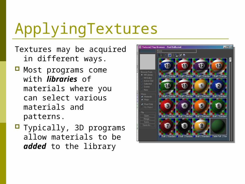
ApplyingTexturesTextures may be acquired
in different ways. Most programs come
with libraries of materials where you can select various materials and patterns.
Typically, 3D programs allow materials to be added to the library
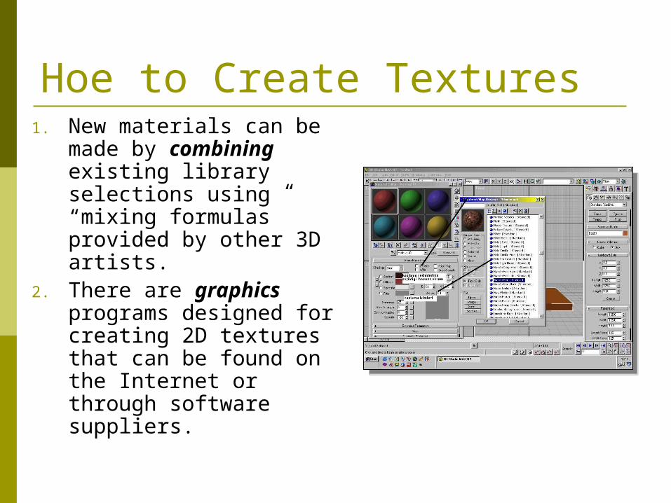
1. New materials can be made by combining existing library selections using “mixing formulas” provided by other 3D artists.
2. There are graphics programs designed for creating 2D textures that can be found on the Internet or through software suppliers.
Hoe to Create Textures
Creating Textures
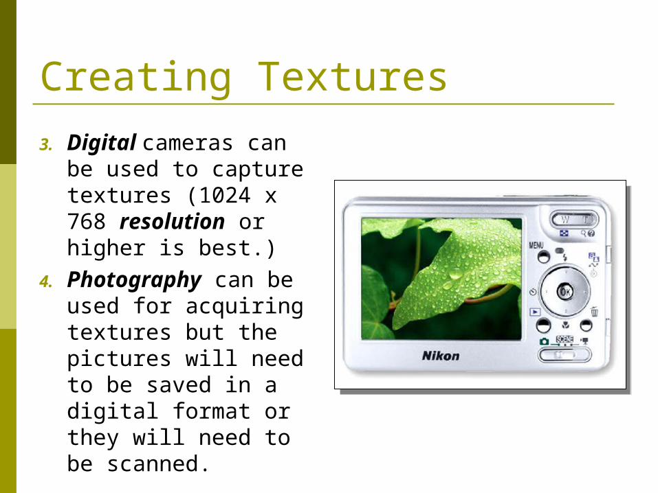
3. Digital cameras can be used to capture textures (1024 x 768 resolution or higher is best.)
4. Photography can be used for acquiring textures but the pictures will need to be saved in a digital format or they will need to be scanned.
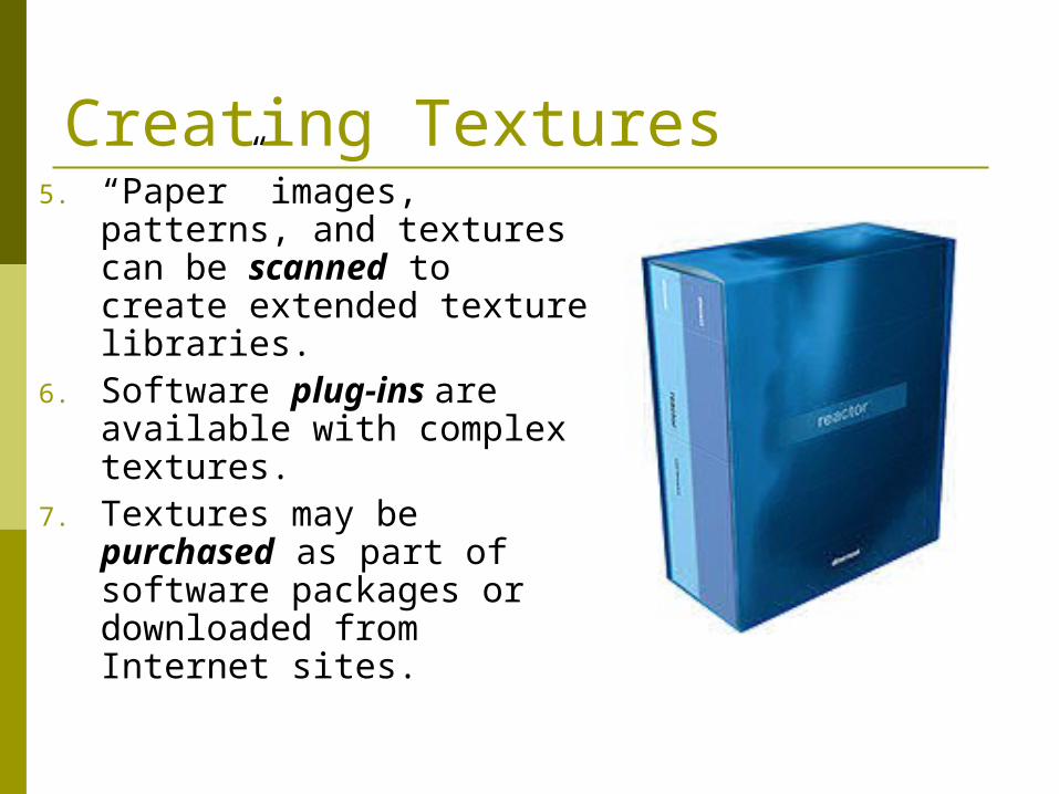
5. “Paper” images, patterns, and textures can be scanned to create extended texture libraries.
6. Software plug-ins are available with complex textures.
7. Textures may be purchased as part of software packages or downloaded from Internet sites.
Creating Textures
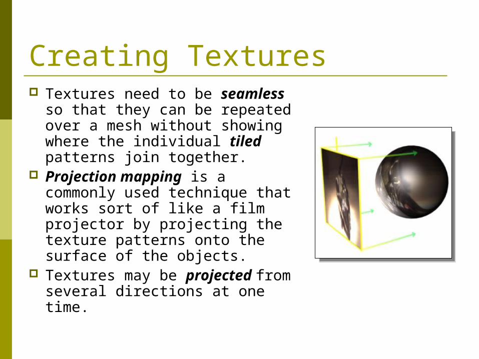
Textures need to be seamless so that they can be repeated over a mesh without showing where the individual tiled patterns join together.
Projection mapping is a commonly used technique that works sort of like a film projector by projecting the texture patterns onto the surface of the objects.
Textures may be projected from several directions at one time.
Creating Textures
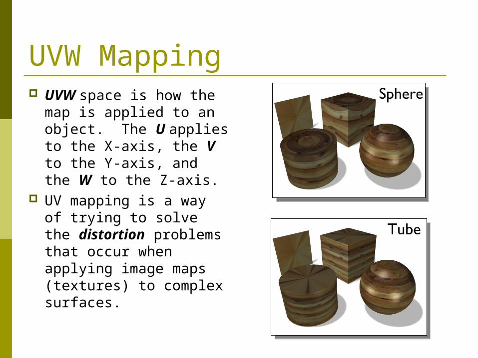
UVW Mapping UVW space is how the
map is applied to an object. The U applies to the X-axis, the V to the Y-axis, and the W to the Z-axis.
UV mapping is a way of trying to solve the distortion problems that occur when applying image maps (textures) to complex surfaces.
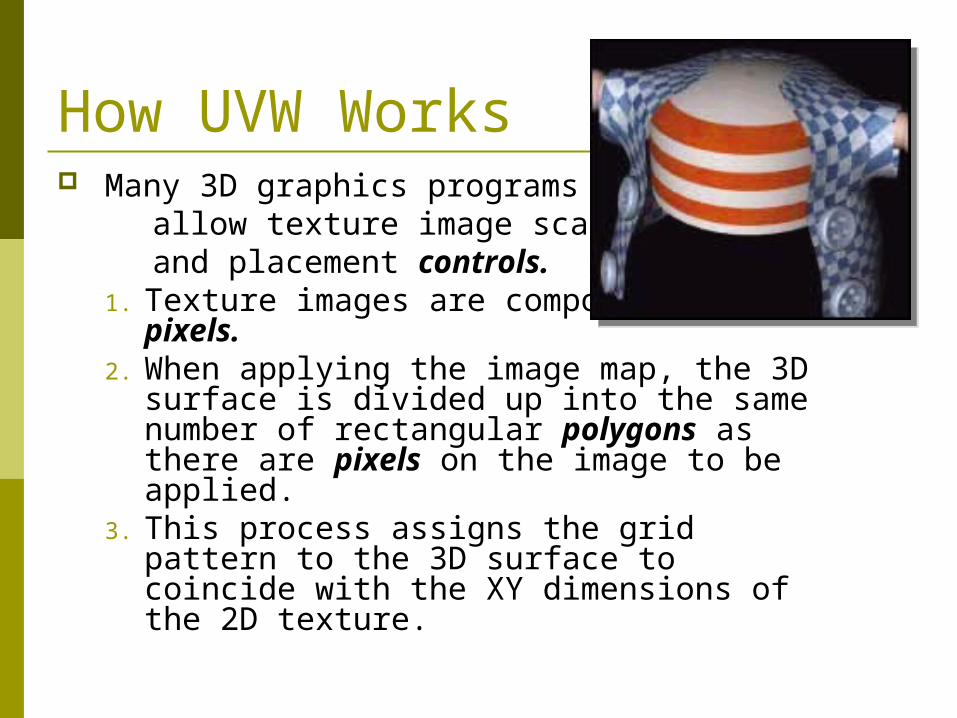
How UVW Works Many 3D graphics programs allow texture image scaling and placement controls.
1. Texture images are composed of 2D pixels.
2. When applying the image map, the 3D surface is divided up into the same number of rectangular polygons as there are pixels on the image to be applied.
3. This process assigns the grid pattern to the 3D surface to coincide with the XY dimensions of the 2D texture.
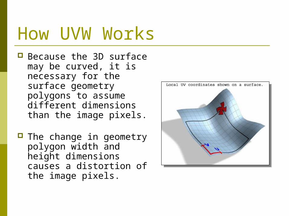
Because the 3D surface may be curved, it is necessary for the surface geometry polygons to assume different dimensions than the image pixels.
The change in geometry polygon width and height dimensions causes a distortion of the image pixels.
How UVW Works
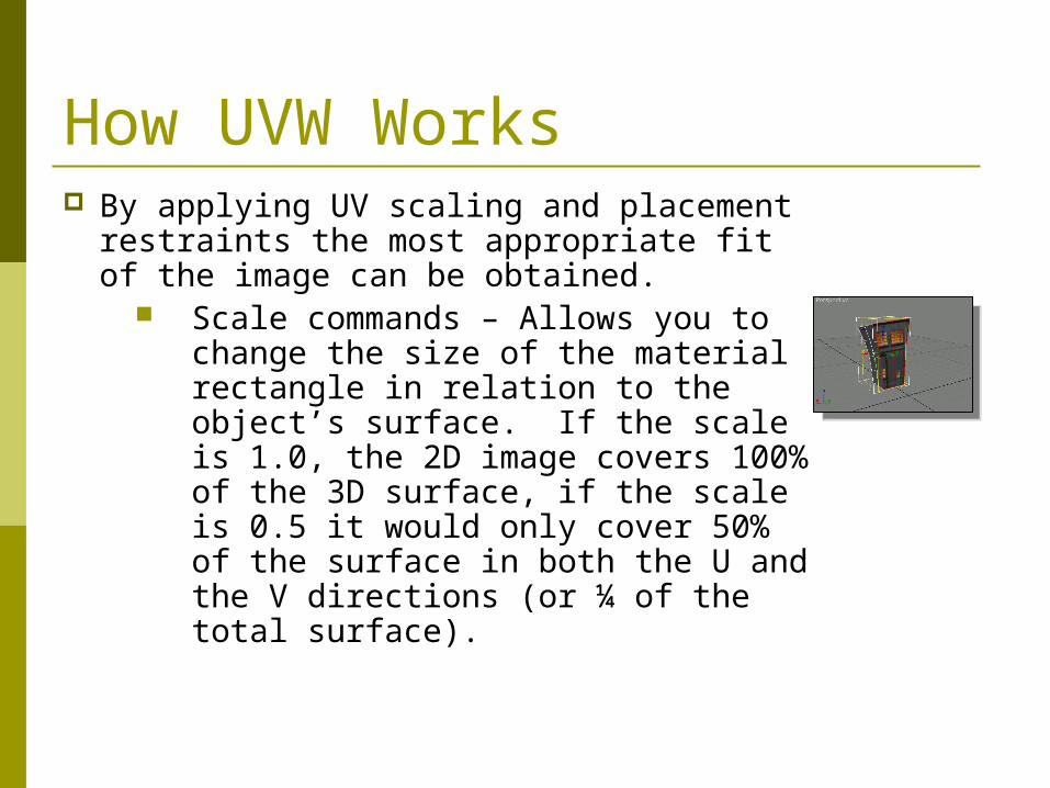
By applying UV scaling and placement restraints the most appropriate fit of the image can be obtained.
Scale commands – Allows you to change the size of the material rectangle in relation to the object’s surface. If the scale is 1.0, the 2D image covers 100% of the 3D surface, if the scale is 0.5 it would only cover 50% of the surface in both the U and the V directions (or ¼ of the total surface).
How UVW Works
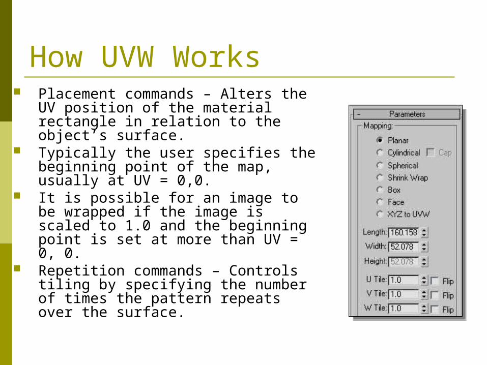
Placement commands – Alters the UV position of the material rectangle in relation to the object’s surface.
Typically the user specifies the beginning point of the map, usually at UV = 0,0.
It is possible for an image to be wrapped if the image is scaled to 1.0 and the beginning point is set at more than UV = 0, 0.
Repetition commands – Controls tiling by specifying the number of times the pattern repeats over the surface.
How UVW Works
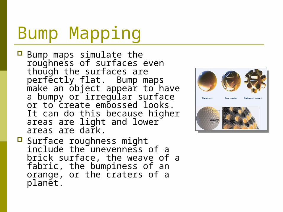
Bump Mapping Bump maps simulate the
roughness of surfaces even though the surfaces are perfectly flat. Bump maps make an object appear to have a bumpy or irregular surface or to create embossed looks. It can do this because higher areas are light and lower areas are dark.
Surface roughness might include the unevenness of a brick surface, the weave of a fabric, the bumpiness of an orange, or the craters of a planet.
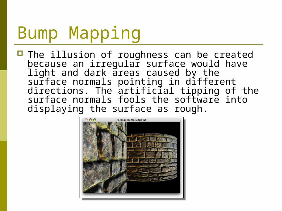
Bump Mapping The illusion of roughness can be created because
an irregular surface would have light and dark areas caused by the surface normals pointing in different directions. The artificial tipping of the surface normals fools the software into displaying the surface as rough.
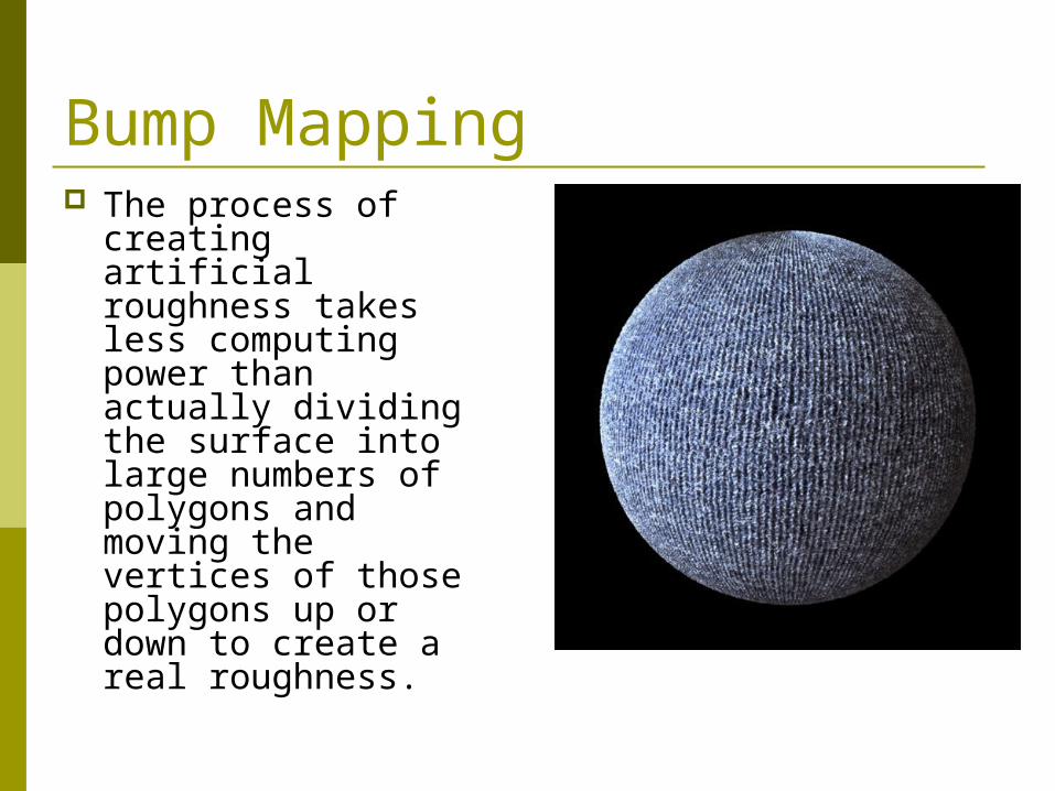
Bump Mapping The process of
creating artificial roughness takes less computing power than actually dividing the surface into large numbers of polygons and moving the vertices of those polygons up or down to create a real roughness.
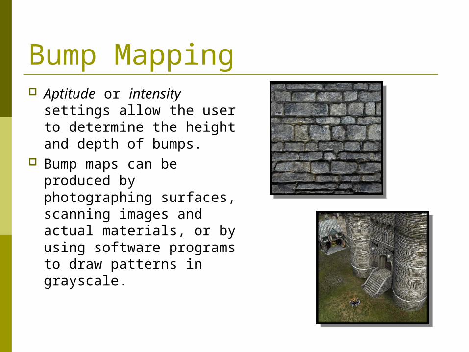
Bump Mapping Aptitude or intensity
settings allow the user to determine the height and depth of bumps.
Bump maps can be produced by photographing surfaces, scanning images and actual materials, or by using software programs to draw patterns in grayscale.
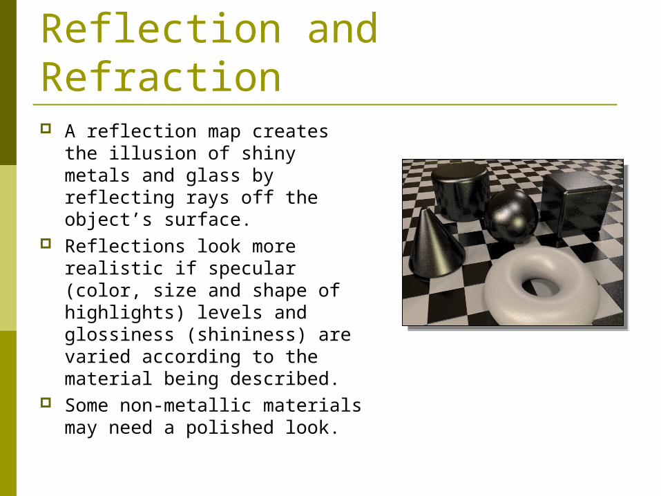
Reflection and Refraction A reflection map creates the
illusion of shiny metals and glass by reflecting rays off the object’s surface.
Reflections look more realistic if specular (color, size and shape of highlights) levels and glossiness (shininess) are varied according to the material being described.
Some non-metallic materials may need a polished look.
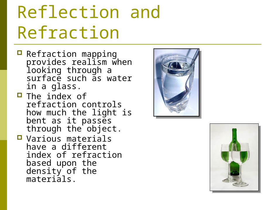
Refraction mapping provides realism when looking through a surface such as water in a glass.
The index of refraction controls how much the light is bent as it passes through the object.
Various materials have a different index of refraction based upon the density of the materials.
Reflection and Refraction
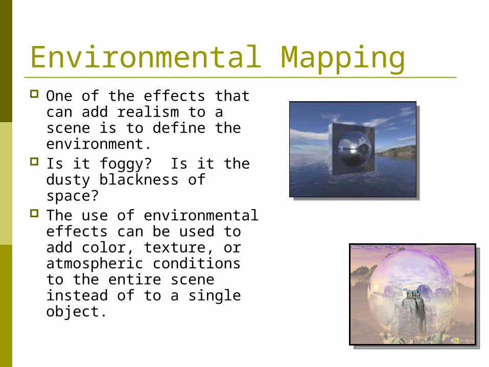
One of the effects that can add realism to a scene is to define the environment.
Is it foggy? Is it the dusty blackness of space?
The use of environmental effects can be used to add color, texture, or atmospheric conditions to the entire scene instead of to a single object.
Environmental Mapping
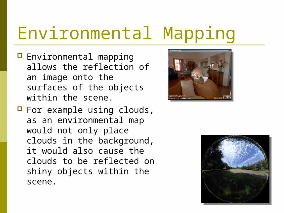
Environmental mapping allows the reflection of an image onto the surfaces of the objects within the scene.
For example using clouds, as an environmental map would not only place clouds in the background, it would also cause the clouds to be reflected on shiny objects within the scene.
Environmental Mapping
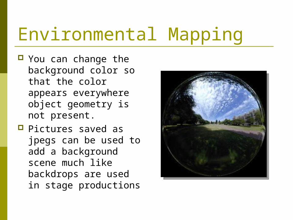
You can change the background color so that the color appears everywhere object geometry is not present.
Pictures saved as jpegs can be used to add a background scene much like backdrops are used in stage productions
Environmental Mapping
In the real world, the colors change depending upon the distance that you are from the object.
The color of a distance object is less vibrant than that of similar objects that are located closer to you.
Most computer graphics programs do not automatically create this effect, but they give you the opportunity to generate atmospheric effects such as fog, haze, fire, and smoke.
Environmental Mapping