marafeq’s design guidelines for the district cooling system · district cooling is an...
TRANSCRIPT
LUSAIL DEVELOPMENT
Marafeq’s Design Guidelines for the Connection of ETS(s) to the
District Cooling System
Document No.: LUS-CPALL-MAQ-SPE-UT-00004
REV. NO. DATE DESCRIPTION PREPARED BY CHECKED
BY APPROVED BY
1 09-08-2011 Anders Tvarne Abdullah Abushaikha D. Reed Phillips
2 12-04-2012 Muhammad Ali Abdullah Abushaikha D. Reed Phillips
3 22-04-2014 Muhammad Ali / Uday Diwakar
Abdullah Abushaikha D. Reed Phillips
4 10-11-2014 Table 3.1, 4.2 and 5.1 revised. Muhammad Ali / Uday Diwakar
Vinod Kesavannair D. Reed Phillips
5 30-09-2017 General editorial, changed primary side scope Bob Miller / Brajesh Kumar / Uday Diwakar
Vinod Kesavannair D. Reed Phillips
Marafeq Qatar L.L.C P.O. Box 5651 Doha - Qatar T: 974 40120120 F: 974 40120121 Website : www.marafeq.com.qa

LUSAIL DEVELOPMENT
CONTENTS
CHANGES FROM REVISION 4 5
1 INTRODUCTION 5
1.1 The District Cooling System 5
1.2 General 6
1.3 Definitions and Acronyms 6
1.4 Norms and Standards 9
1.5 Design Criteria 10
2 DEFINITION OF RESPONSIBILITIES 11
3 MARAFEQ’S SCOPE OF WORK 14
3.1 Energy Meter, Flow Meter and Temperature Sensors 14
3.2 Heat Exchanger 15
3.3 Pressure Independent Control Valve 16
3.4 Programmable Logic Controller 18
3.5 Pressure Safety Relief Valve 18
3.6 Welded Ball Valves 18
4 CUSTOMER’S SCOPE OF WORK 19
4.1 ETS Plant Room 19
4.2 Communication 20
4.3 Primary Service Lines 20
4.4 ETS 21
4.5 Customer Secondary-Side Chilled Water System 21
4.6 Pipe Cleaning and Commissioning 22
4.7 Pressure Tests, Inspections, and Quality Control 22
4.8 Procedures for Connection to District Cooling 23
4.9 ETS Installation and Component Requirements 23
Project Name: Lusail Development District Cooling Distribution System
Marafeq’s Design Guidelines for the Connection of ETS to the DC System V.5 (Sep-2017) 2 | P a g e

LUSAIL DEVELOPMENT
4.10 Make-up Water and Chemical Water Treatment on the Secondary Systems 24
5 TECHNICAL SPECIFICATIONS 24
5.1 Above Ground Pipes and Fittings 24
5.2 Buried Pipes and Fittings 25
5.3 Isolation Valves 27
5.4 CIP Connection 28
5.5 Strainers 28
5.6 PLC System 28
5.6.1 Human Machine Interface (HMI) 28
5.6.2 PLC configuration: 29
5.6.3 Uninterruptible Power Supply (UPS): 29
5.6.4 Project record documents: 29
5.7 Measuring Devices 29
5.7.1 General Requirements 30
5.7.2 Instruments and Gauges 30
5.7.3 Instrument Wiring 32
5.7.4 Cable Identification 32
5.7.5 Installation - General 33
5.8 Vent and Drain Valves 33
5.9 Connection with the District Cooling Network 33
5.10 Jointing 33
5.11 Insulation 34
5.12 Tagging 34
5.13 Changes to the System 35
6 APPENDICES 35 Appendix 1: District Cooling Design Conformance Certificate
Appendix 2: ETS examination summary for “ETS Conformance Certificate”
Appendix 3.1: Schematic of ETS installation for single heat exchanger
Project Name: Lusail Development District Cooling Distribution System
Marafeq’s Design Guidelines for the Connection of ETS to the DC System V.5 (Sep-2017) 3 | P a g e

LUSAIL DEVELOPMENT
Appendix 3.2: Schematic of ETS installation for multiple heat exchanger
Appendix 4.1: Compliance statement: method statement for installation, testing and commissioning of
equipment inside ETS (primary side)
Appendix 4.2: Compliance statement: method statement for hydro static test (primary side)
Appendix 4.3: Compliance statement: method statement for flushing/pipe conditioning (primary side) List of Tables Table 1 Definitions and Acronyms .......................................................................................................... 6 Table 2 Design Criteria ......................................................................................................................... 10 Table 3 Definition of Responsibilities .................................................................................................... 11 Table 4 Numbers of PHEs versus Requested Capacity ....................................................................... 14 Table 5 Water Quality Criteria ............................................................................................................... 22 Table 6 Pipe Dimensions ...................................................................................................................... 25 Table 7 Insulation Properties ................................................................................................................ 26 Table 8 Casing Jacket Properties ......................................................................................................... 26 Table 9 Casing Jacket Dimensions ....................................................................................................... 27
List of Figures Figure 1: District cooling system general schematic ............................................................................... 6 Figure 2 ETS Bulk meter schematic diagram ....................................................................................... 15
Project Name: Lusail Development District Cooling Distribution System
Marafeq’s Design Guidelines for the Connection of ETS to the DC System V.5 (Sep-2017) 4 | P a g e

LUSAIL DEVELOPMENT
Changes from Revision 4 In Revision 4 of the ETS Guide, Marafeq supplied some instruments, and flow and energy meter, and the Customer was responsible for everything else including design, procurement, installation, and testing and commissioning. To assure quality, Marafeq provided guidelines, requirements, and specifications to guide the Customer. Marafeq also required the Customer to submit documents for design and materials demonstrating compliance with the guideline. In this revision 5, Marafeq provides more ETS equipment so the Customer’s responsibility is less.
Marafeq’s scope now includes design of the primary side of the ETS and supply of five (5) major materials including plate heat exchanger, programmable logic controller, pressure independent control valve, welded isolation ball valves, and pressure safety relief valves, in addition to the previous scope of temperature and differential pressure transmitters and flow/energy meter defined in Revision 4. In addition, during construction, which is the Customer’s scope of work, Marafeq will inspect the primary side works of the ETS and witness testing and commissioning. As outlined in the Utility Application Procedures, Marafeq will let the Customer know the stipulated price of above scope.
Any statements in previous revisions no longer apply.
In the narrative that follows we write the scopes of work for Marafeq and the Customer, but in some cases Marafeq supplies one component and the Customer supplies another. Take for example the flow meter. Marafeq supplies the meter but the Customer provides the meter run (piping). So under the Marafeq scope of work you will see it mentioned that the Customer provides the meter run. This is necessary to present a complete picture and should not be taken as a conflict in scope of work. The scope of work is defined by Clause 2 and the schematics in Appendix 3. If you see a discrepancy or are unclear about the scope of work, please contact us as soon as possible.
1 INTRODUCTION
1.1 The District Cooling System
The Energy Transfer Station (ETS) in Lusail city is the Customer's part of the district cooling system. The district cooling system will be operated by Marafeq. This “Marafeq’s Design Guidelines for the Connection of ETS (s) to the District Cooling System” (Document No LUS-CPAA-MAQ-SPE-UT-004) identifies the general principles and technical requirements to be applied to the design and construction of energy transfer stations. Since the ETS is a part of the district cooling system, the ETS it must be built, maintained and operated in such a way that it complies with the requirements of this document.
District cooling is an environmentally friendly technology for producing and distributing refrigeration to real estate. For an efficient system all included parts of the supply chain need to function efficient. A district cooling system consists of centralized production plant(s), a distribution network, and ETS’s. Marafeq here describes requirements for the ETS in order to optimize the district cooling system function.
Project Name: Lusail Development District Cooling Distribution System
Marafeq’s Design Guidelines for the Connection of ETS to the DC System V.5 (Sep-2017) 5 | P a g e

LUSAIL DEVELOPMENT
Figure 1: District cooling system general schematic
1.2 General
This document describes the technical requirements for connecting to Marafeq’s district cooling system. This document should be used for planning, preparation of specifications, and procurement during initial design phases in advance of the formal agreement between Marafeq and Customers or end-users. All technical requirements that apply for connecting to the District Cooling Network are specified in this document.
1.3 Definitions and Acronyms
Table 1 Definitions and Acronyms
AHRI Air-Conditioning, Heating and Refrigeration Institute
ASHRAE American Society of Heating, Refrigerating and Air-Conditioning Engineers, Inc.
BSRIA Building Services Research and Information Association
BMS Building Management System used to control the secondary side
Btu British thermal unit
CIBSE The Chartered Institution of Building Services Engineers
Client The master developer - Lusail Real Estate Development Company (LREDC) or its appointed representative.
Project Name: Lusail Development District Cooling Distribution System
Marafeq’s Design Guidelines for the Connection of ETS to the DC System V.5 (Sep-2017) 6 | P a g e
LUSAIL DEVELOPMENT
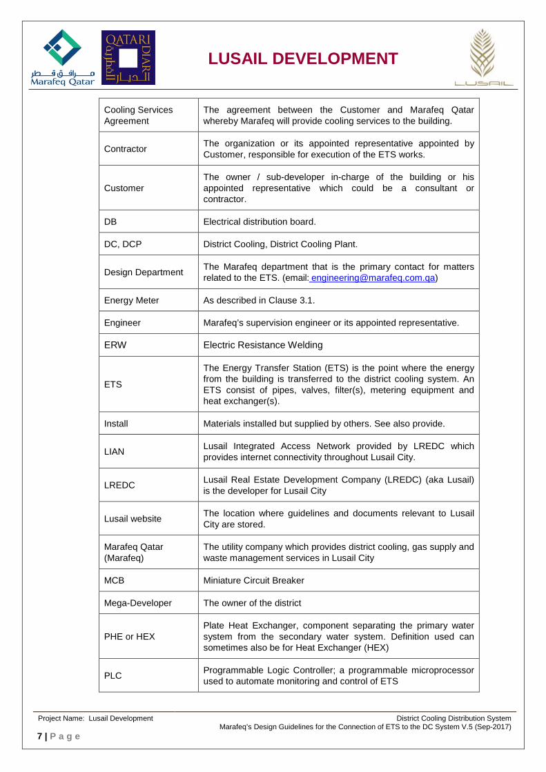
Cooling Services Agreement
The agreement between the Customer and Marafeq Qatar whereby Marafeq will provide cooling services to the building.
Contractor The organization or its appointed representative appointed by Customer, responsible for execution of the ETS works.
Customer The owner / sub-developer in-charge of the building or his appointed representative which could be a consultant or contractor.
DB Electrical distribution board.
DC, DCP District Cooling, District Cooling Plant.
Design Department The Marafeq department that is the primary contact for matters related to the ETS. (email: [email protected])
Energy Meter As described in Clause 3.1.
Engineer Marafeq’s supervision engineer or its appointed representative.
ERW Electric Resistance Welding
ETS
The Energy Transfer Station (ETS) is the point where the energy from the building is transferred to the district cooling system. An ETS consist of pipes, valves, filter(s), metering equipment and heat exchanger(s).
Install Materials installed but supplied by others. See also provide.
LIAN Lusail Integrated Access Network provided by LREDC which provides internet connectivity throughout Lusail City.
LREDC Lusail Real Estate Development Company (LREDC) (aka Lusail) is the developer for Lusail City
Lusail website The location where guidelines and documents relevant to Lusail City are stored.
Marafeq Qatar (Marafeq)
The utility company which provides district cooling, gas supply and waste management services in Lusail City
MCB Miniature Circuit Breaker
Mega-Developer The owner of the district
PHE or HEX Plate Heat Exchanger, component separating the primary water system from the secondary water system. Definition used can sometimes also be for Heat Exchanger (HEX)
PLC Programmable Logic Controller; a programmable microprocessor used to automate monitoring and control of ETS
Project Name: Lusail Development District Cooling Distribution System
Marafeq’s Design Guidelines for the Connection of ETS to the DC System V.5 (Sep-2017) 7 | P a g e
LUSAIL DEVELOPMENT
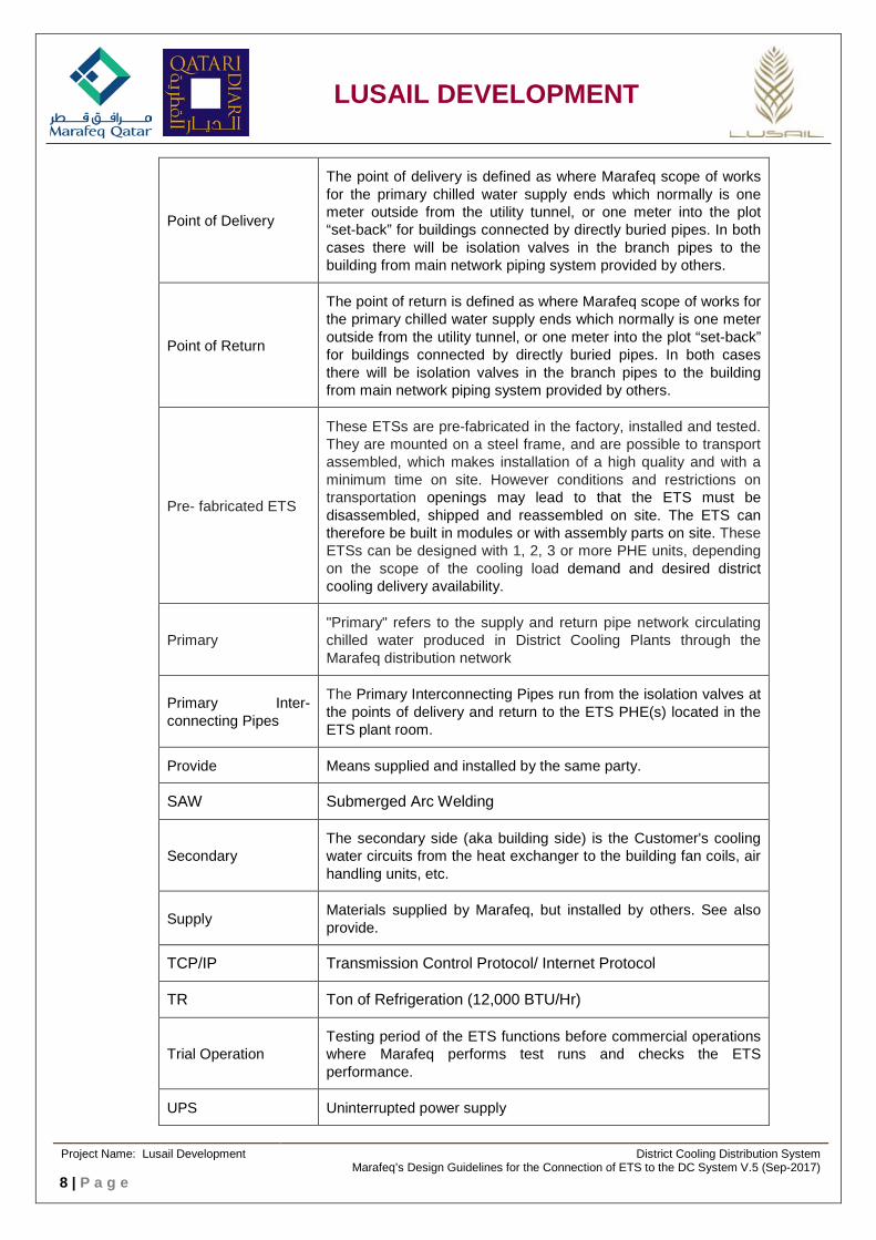
Point of Delivery
The point of delivery is defined as where Marafeq scope of works for the primary chilled water supply ends which normally is one meter outside from the utility tunnel, or one meter into the plot “set-back” for buildings connected by directly buried pipes. In both cases there will be isolation valves in the branch pipes to the building from main network piping system provided by others.
Point of Return
The point of return is defined as where Marafeq scope of works for the primary chilled water supply ends which normally is one meter outside from the utility tunnel, or one meter into the plot “set-back” for buildings connected by directly buried pipes. In both cases there will be isolation valves in the branch pipes to the building from main network piping system provided by others.
Pre- fabricated ETS
These ETSs are pre-fabricated in the factory, installed and tested. They are mounted on a steel frame, and are possible to transport assembled, which makes installation of a high quality and with a minimum time on site. However conditions and restrictions on transportation openings may lead to that the ETS must be disassembled, shipped and reassembled on site. The ETS can therefore be built in modules or with assembly parts on site. These ETSs can be designed with 1, 2, 3 or more PHE units, depending on the scope of the cooling load demand and desired district cooling delivery availability.
Primary "Primary" refers to the supply and return pipe network circulating chilled water produced in District Cooling Plants through the Marafeq distribution network
Primary Inter-connecting Pipes
The Primary Interconnecting Pipes run from the isolation valves at the points of delivery and return to the ETS PHE(s) located in the ETS plant room.
Provide Means supplied and installed by the same party.
SAW Submerged Arc Welding
Secondary The secondary side (aka building side) is the Customer's cooling water circuits from the heat exchanger to the building fan coils, air handling units, etc.
Supply Materials supplied by Marafeq, but installed by others. See also provide.
TCP/IP Transmission Control Protocol/ Internet Protocol
TR Ton of Refrigeration (12,000 BTU/Hr)
Trial Operation Testing period of the ETS functions before commercial operations where Marafeq performs test runs and checks the ETS performance.
UPS Uninterrupted power supply
Project Name: Lusail Development District Cooling Distribution System
Marafeq’s Design Guidelines for the Connection of ETS to the DC System V.5 (Sep-2017) 8 | P a g e
LUSAIL DEVELOPMENT
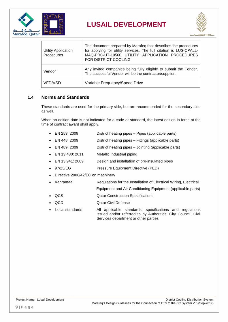
Utility Application Procedures
The document prepared by Marafeq that describes the procedures for applying for utility services. The full citation is LUS-CPALL-MAQ-PRC-UT-10560 UTILITY APPLICATION PROCEDURES FOR DISTRICT COOLING
Vendor Any invited companies being fully eligible to submit the Tender. The successful Vendor will be the contractor/supplier.
VFD/VSD Variable Frequency/Speed Drive
1.4 Norms and Standards
These standards are used for the primary side, but are recommended for the secondary side as well. When an edition date is not indicated for a code or standard, the latest edition in force at the time of contract award shall apply.
• EN 253: 2009 District heating pipes – Pipes (applicable parts)
• EN 448: 2009 District heating pipes – Fittings (applicable parts)
• EN 489: 2009 District heating pipes – Jointing (applicable parts)
• EN 13 480: 2011 Metallic industrial piping
• EN 13 941: 2009 Design and installation of pre-insulated pipes
• 97/23/EG Pressure Equipment Directive (PED)
• Directive 2006/42/EC on machinery
• Kahramaa Regulations for the Installation of Electrical Wiring, Electrical
Equipment and Air Conditioning Equipment (applicable parts)
• QCS Qatar Construction Specifications
• QCD Qatar Civil Defense
• Local standards All applicable standards, specifications and regulations issued and/or referred to by Authorities, City Council, Civil Services department or other parties
Project Name: Lusail Development District Cooling Distribution System
Marafeq’s Design Guidelines for the Connection of ETS to the DC System V.5 (Sep-2017) 9 | P a g e
LUSAIL DEVELOPMENT
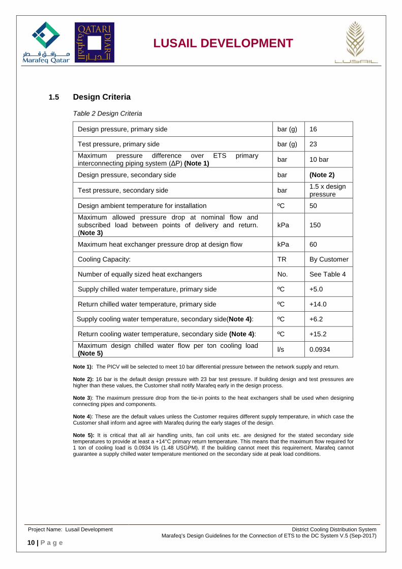
1.5 Design Criteria
Table 2 Design Criteria
Design pressure, primary side bar (g) 16
Test pressure, primary side bar (g) 23
Maximum pressure difference over ETS primary interconnecting piping system (ΔP) (Note 1) bar 10 bar
Design pressure, secondary side bar (Note 2)
Test pressure, secondary side bar 1.5 x design pressure
Design ambient temperature for installation ºC 50
Maximum allowed pressure drop at nominal flow and subscribed load between points of delivery and return. (Note 3)
kPa 150
Maximum heat exchanger pressure drop at design flow kPa 60
Cooling Capacity: TR By Customer
Number of equally sized heat exchangers No. See Table 4
Supply chilled water temperature, primary side ºC +5.0
Return chilled water temperature, primary side ºC +14.0
Supply cooling water temperature, secondary side(Note 4): ºC +6.2
Return cooling water temperature, secondary side (Note 4): ºC +15.2
Maximum design chilled water flow per ton cooling load (Note 5) l/s 0.0934
Note 1): The PICV will be selected to meet 10 bar differential pressure between the network supply and return. Note 2): 16 bar is the default design pressure with 23 bar test pressure. If building design and test pressures are higher than these values, the Customer shall notify Marafeq early in the design process. Note 3): The maximum pressure drop from the tie-in points to the heat exchangers shall be used when designing connecting pipes and components. Note 4): These are the default values unless the Customer requires different supply temperature, in which case the Customer shall inform and agree with Marafeq during the early stages of the design. Note 5): It is critical that all air handling units, fan coil units etc. are designed for the stated secondary side temperatures to provide at least a +14°C primary return temperature. This means that the maximum flow required for 1 ton of cooling load is 0.0934 l/s (1.48 USGPM). If the building cannot meet this requirement, Marafeq cannot guarantee a supply chilled water temperature mentioned on the secondary side at peak load conditions.
Project Name: Lusail Development District Cooling Distribution System
Marafeq’s Design Guidelines for the Connection of ETS to the DC System V.5 (Sep-2017) 10 | P a g e

LUSAIL DEVELOPMENT
2 Definition of Responsibilities
Marafeq will supply the components identified in the tables below under ‘Marafeq’ at charges applicable at the time of the project. The tables below should be read in conjunction with the ETS schematics in Appendix 3. Customer’s scope is also identified below.
Table 3 Definition of Responsibilities
ETS Room
Description Supplied by
Installed by
Lighting Customer Customer
Electrical supply Customer Customer
Air conditioning Customer Customer
Fire detection Customer Customer
Floor drain Customer Customer
Potable water supply Customer Customer
Wall and floor penetrations Customer Customer
Access to install / remove equipment Customer Customer
Equipment
Description Supplied by
Installed by
Heat exchanger(s) Marafeq Customer
Secondary side pumps Customer Customer
Pressurization system Customer Customer
Expansion tanks Customer Customer
Water treating equipment Customer Customer
Instruments
Description Supplied by
Installed by
Cable Terminations by
Primary side temperature transmitters including thermowells (2 nos.) Marafeq Customer Marafeq
Flow meter Marafeq Customer Marafeq
Energy meter Marafeq Customer Marafeq
Project Name: Lusail Development District Cooling Distribution System
Marafeq’s Design Guidelines for the Connection of ETS to the DC System V.5 (Sep-2017) 11 | P a g e

LUSAIL DEVELOPMENT
Secondary side temperature transmitters including thermowells (2 nos.) Marafeq Customer Marafeq
Pressure independent control valve(s) for primary side Marafeq Customer Marafeq
Programmable logic controller (PLC) including panel Marafeq Customer Marafeq
Uninterrupted power supply (UPS) for PLC system Marafeq Marafeq Marafeq
Wireless communication from ETS PLC to district cooling plant (until fiber optic connectivity is available)
Marafeq Marafeq Marafeq
Fiber optic connectivity from the Lusail Integrated Access Network (LIAN) to the Customer’s telecommunications room
LREDC/ Ooredoo
LREDC/ Ooredoo Customer
Fiber optic/Ethernet cable from Customer’s telecommunications room to the ETS PLC Customer Customer Customer
Wiring and containment for controls and power including energy meter, instruments, control valve(s), PLC panel, Customer’s building automation system, etc.
Customer Customer Marafeq
Piping Components
Description Supplied by
Installed by
Primary side isolation ball valves Marafeq Customer
Heat exchanger pressure relief valves (2 no. per PHE) Marafeq Customer
Primary side pipe, fittings, flanges, and vent and drain valves Customer Customer
Threadolets for instruments for both primary and secondary side Customer Customer
Spool pieces to replace meter, control valve, heat exchanger, etc. during flushing Customer Customer
Meter run (up and downstream straight runs) Customer Customer
Strainers Customer Customer
Pressure and temperature gauges together with root valves and thermo wells Customer Customer
All secondary side pumps, valves, control valves, piping, and related components Customer Customer
Project Name: Lusail Development District Cooling Distribution System
Marafeq’s Design Guidelines for the Connection of ETS to the DC System V.5 (Sep-2017) 12 | P a g e

LUSAIL DEVELOPMENT
Testing and Commissioning
Description by
Hydrostatic testing, flushing, and chemical treatment (primary and secondary sides) Customer
Commissioning PLC system, energy meter, and integrating communication between the ETS and the DCP for both fiber optic and wireless communications
Marafeq
Project Name: Lusail Development District Cooling Distribution System
Marafeq’s Design Guidelines for the Connection of ETS to the DC System V.5 (Sep-2017) 13 | P a g e

LUSAIL DEVELOPMENT
3 Marafeq’s Scope of Work
Marafeq will provide preliminary designs illustrating the space required for the ETS. These preliminary layouts will be provided within the timeframe outlined in the Utility Application Procedures.
Marafeq will prepare the detailed design of the primary side of the ETS, supply the equipment listed in Clause 2, and inspect the primary side installed by the Customer. The design will cover from the points of delivery/return to the primary side of the heat exchangers but not piping on the secondary side which is in the Customer’s scope of work. The design will include:
a. ETS room primary side design drawings showing plan and sections together with details
b. Primary service line routing together with plan and details
c. Pressure drop calculation (For internal use of Marafeq)
d. Flow meter sizing (For internal use of Marafeq)
The numbers of heat exchangers that Marafeq will be considering in design and supply are listed below. If the Customer wants additional heat exchangers or redundant capacity Marafeq can supply them at additional cost in accordance with Utility Application Procedures.
Table 4 Numbers of PHEs versus Requested Capacity
Requested capacity (TR)
Number and portion
Up to 200 One at 100%
201 to 1,000 Two at 50%
1,001 to 3,000 Three at 33-1/3 %
3,001 and above To be determined by Marafeq based on space, design etc.
3.1 Energy Meter, Flow Meter and Temperature Sensors
The metering equipment includes the supply and return pipe temperature sensor and the supply pipe flow meter. Marafeq shall supply ETS energy metering equipment that will be used for billing purpose. Marafeq will supervise the installation and wiring of energy meters. The Customer shall provide a dummy (spool piece) for the flow meter during flushing operations. Energy meters will be used for billing of chiller water energy consumption based on the flow meter and temperature sensors. The energy meter automatically calculates water density and enthalpy. From the flow meter, volume flow is converted into mass flow and used to calculate thermal energy.
1. Energy meter shall be equipped with its necessary flow meter and temperature sensors and shall be provided for billing computation. Metering accuracy shall comply with EN 1434, Class 1.
2. Supply and return temperature shall be measured via resistance temperature devices (RTDs), 4-wire, Pt 500, and shall use matched pairs, class A to IEC 751 standard.
Project Name: Lusail Development District Cooling Distribution System
Marafeq’s Design Guidelines for the Connection of ETS to the DC System V.5 (Sep-2017) 14 | P a g e
LUSAIL DEVELOPMENT
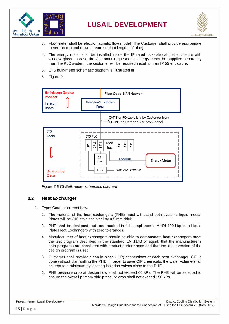
3. Flow meter shall be electromagnetic flow model. The Customer shall provide appropriate meter run (up and down stream straight lengths of pipe).
4. The energy meter shall be installed inside the IP rated lockable cabinet enclosure with window glass. In case the Customer requests the energy meter be supplied separately from the PLC system, the customer will be required install it in an IP 55 enclosure.
5. ETS bulk-meter schematic diagram is illustrated in
6. Figure 2.
Figure 2 ETS Bulk meter schematic diagram
3.2 Heat Exchanger
1. Type: Counter-current flow.
2. The material of the heat exchangers (PHE) must withstand both systems liquid media. Plates will be 316 stainless steel by 0.5 mm thick
3. PHE shall be designed, built and marked in full compliance to AHRI-400 Liquid-to-Liquid Plate Heat Exchangers with zero tolerances.
4. Manufacturers of heat exchangers should be able to demonstrate heat exchangers meet the test program described in the standard EN 1148 or equal; that the manufacturer's data programs are consistent with product performance and that the latest version of the design program is used.
5. Customer shall provide clean in place (CIP) connections at each heat exchanger. CIP is done without dismantling the PHE. In order to save CIP chemicals, the water volume shall be kept to a minimum by locating isolation valves close to the PHE.
6. PHE pressure drop at design flow shall not exceed 60 kPa. The PHE will be selected to ensure the overall primary side pressure drop shall not exceed 150 kPa.
Project Name: Lusail Development District Cooling Distribution System
Marafeq’s Design Guidelines for the Connection of ETS to the DC System V.5 (Sep-2017) 15 | P a g e
LUSAIL DEVELOPMENT
7. The frames of gasketed PHEs will be specified to have 20% extra space for adding plates in the future. For brazed plate heat exchangers, space will be provided to add an additional 20% plate pack.
8. If the PHE is sized for future expansion allowance, this shall be based on flow capacity by installing additional plates in future with the following limitations:
a) Design temperatures shall remain the same.
b) Pressure drops across the heat exchanger shall not increase by more than 10% above design conditions. On the primary side, do not exceed 150 kPa overall pressure drop.
c) Additional capacity is obtained without changing frame size.
9. The design shall prevent fluid intermixing.
10. The unit shall withstand the maximum 16 bar gauge design pressure on primary side with opposite side at 0 psig gauge. Similarly unit shall withstand the maximum design pressure of 16 bar on secondary side with opposite side at 0 psig gauge.
11. Metal nameplate shall be provided so it is visible outside the insulation with identification in accordance with the project schedule. Include:
a. design flow in l/sec
b. design kW (TR)
c. Hot side and cold side temperature in and out, ˚C.
d. Hot side and cold side pressure drop, kPa
e. Design temperature differential, ˚C.
f. Provide metal tags to label inlet and outlet connections for hot side and cold side of heat exchanger.
12. A safety relief valve shall be located between the isolation valves at each heat exchanger in order to prevent over pressure during shut downs.
13. Service Conditions
a. Design Pressure: 16 Bars (minimum) 1
b. Test Pressure: 23 Bars
c. Suitable for water Temperature Condition: Supply: 4-10 ˚C, Return: 6-20 ˚C
d. Suitable for ambient temperature: 50 ˚C
3.3 Pressure Independent Control Valve
1. One Pressure Independent Control Valve (PICV) shall be provided for each PHE.
2. PICV flanges shall be as per ANSI class 150. Matching flanges shall be considered by the Customer for installing PICV.
3. The control valve is suitable for precise control and shall maintain linear characteristic under all operating condition.
4. Valve rating is suitable for network design pressure: 16 bar. Test pressure: 23 bar for 6 hours. Differential Pressure 10 bar.
5. Pressure drop across PICV at full flow condition not to exceed 40 kPa.
Project Name: Lusail Development District Cooling Distribution System
Marafeq’s Design Guidelines for the Connection of ETS to the DC System V.5 (Sep-2017) 16 | P a g e

LUSAIL DEVELOPMENT
6. Confirm that valve pressure drop (for full flow) is accounted in determining the maximum allowed pressure drop of 150 kPa at nominal flow and subscribed load between incoming isolation valve at the wall penetration.
7. Pressure Independent Control Valves (PICVs) shall be installed as shown in the drawings and strictly as per the recommendations of the manufacturer.
8. These valves shall be of pressure independent design and shall consist of two functional items. First part is a two way modulating control valve with electric actuator and the second part is an integral and external differential pressure control valve.
9. The differential pressure control valve shall sense and regulate the differential pressure across the modulating control valve, as per the control valve selection at all flow and pressure conditions.
10. The valves shall be manufactured in accordance with ISO 9001 quality standards.
11. Each valve set shall be pre-calibrated at manufacturer’s works to a specified flow and differential pressure, which shall be field adjustable without the removal of the actuator.
12. Control valve range ability shall be 100:1. The actuators provided with the valve(s) shall assure 100:1 turndown.
13. Class IV leakage or better is required for control valves up to 50 mm diameter and Class III or better for valves larger than 50 mm, as per ANSI leakage testing standards.
14. All valves shall have three integral test ports, factory installed, capable of being used to measure pressure or temperature.
15. The control valve flow adjustment stem shall extend out from the control valve and have an indicator that shall be used to verify valve position. The control valve shall have tapped mounting holes for mounting the control valve actuator bracket. The actuator shall rotate the valve stem to provide the required flow independent of pressure across the valve.
16. Actuators shall modulate all valves from 0 to 100% design flow while rotating the valve stem a maximum of 90° or moving full stroke. Valve percentage opening and closing indication is required.
17. Valve actuators shall be factory mounted.
18. Actuators shall be selected based on system close-off requirements. Valves and actuator shall be capable of a close-off rating of 10 bar.
19. Torque and linear force requirements for actuator selection shall be provided by the valve manufacturer
20. For electric actuation it shall be possible to set the end stroke of the actuator with mechanical stops, signal adjustment, or a control signal limit at the full design flow listed on the performance tag furnished with each valve.
21. In case of power failure valve shall retain its last position.
22. Electric actuator shall be suitable for input and output 4-20 mA control signal.
23. Pressure Independent control valves shall be suitable for thermal insulation all around.
24. Control valves together with actuators shall be suitable to work at ambient temperature of 0 to 50 °C and relative humidity of up to 100%.
25. Actuator housing shall be IP 54 rated or higher.
26. Valve actuator shall have remote, local, and stop selector switch / push button with visual indication of remote/Local/Stop status and % opening of the valve. Selector switch position shall be communicated via digital input, potential free contact, to the ETS PLC.
27. Valve actuator shall be capable to receive remote signals from HMI or SCADA.
Project Name: Lusail Development District Cooling Distribution System
Marafeq’s Design Guidelines for the Connection of ETS to the DC System V.5 (Sep-2017) 17 | P a g e
LUSAIL DEVELOPMENT
28. In local mode, the control valve shall be capable of manual operation (hand wheel or other).
3.4 Programmable Logic Controller
PLC system shall be used for control, monitoring and data acquisition at the Energy Transfer Station. Supply, design, engineering, testing, and commissioning of the system will be carried out by Marafeq Qatar. Please refer Clause 2 Definitions of Responsibilities and refer to clause 5.6 PLC system.
3.5 Pressure Safety Relief Valve
A safety relief valve shall be located between the isolation valves at each heat exchanger in order to prevent overpressure during shut downs. The valve shall be sized for thermal expansion at design load conditions and the set pressure shall be equal to the heat exchanger design pressure.
1. Direct spring loaded type (proportional flow).
2. Lever operated, with non-adjustable factory set discharge pressure.
3.6 Welded Ball Valves
1. All isolation valves on primary side shall be welded type. All valves shall be of industrial standard. Flanges are not allowed.
2. Primary system valves must be thermally insulated with closed cell elastomeric material type with a protective jacket.
3. Main isolation valves for bypass and emergency supply shall be located directly inside the building as close as possible to the walls. Emergency connections shall be accessible from outside at grade level. If valves cannot be located inside, then main isolation valves for bypass and emergency supply shall be pre-insulated and located in a valve chamber located outside the building wall. Emergency connections shall be accessible from outside at grade level.
4. Connection to the district cooling network shall be by welding.
5. Isolation valves must be provided in the supply and return pipe around the heat exchanger(s) to allow for maintenance and cleaning.
6. For welded valves, caution is needed so that the seals in the valves will not be damaged during the welding process.
7. All valves shall be easily accessible and tagged according to with BS 1710 or equal.
8. Valve shall be capable to perform at design pressure of 16 bars and test pressure of 24 bars for 6 hours.
9. Provide hand wheel and gear box for valves DN 200 and above.
10. Provide chain operators for elevated valves. Chain operation shall be provided for valve DN 65 and larger, located 2.2 m (7 feet) or higher above finished floor level. Chain shall be extended to elevation of 1.5 m (5 feet) above finished floor level.
11. Ball seats shall be spring-loaded.
12. Stem shall be provided with double sealing, minimum two O-rings and the upper one shall be changeable from the top without draining the pipeline. (The O-rings are FPM (fluorine rubber/fluoro packing material/VITON) rubber material.
Project Name: Lusail Development District Cooling Distribution System
Marafeq’s Design Guidelines for the Connection of ETS to the DC System V.5 (Sep-2017) 18 | P a g e

LUSAIL DEVELOPMENT
13. Valve shall be full port valve. Reduced port valves are acceptable only if maximum allowable pressure loss of 150 kPa at nominal flow and subscribed load between isolation valves at ETS entrance can be maintained with reduced port valves.
14. Valve shall be provided with position indicator that shows the ball's position in the valve.
15. Valves shall be delivered with plastic end caps (flow port protectors) in order to avoid debris in the valves during transportation, storing, and handling.
16. Pre-insulated valves shall comply with EN 488.
4 Customer’s Scope of Work
The Customer shall pay Marafeq for design services, equipment, and components supplied by Marafeq. Marafeq reserves the right to observe, inspect, and approve the primary side ETS installation, but the Customer is responsible for construction and supervision. The Customer shall arrange and provide temporary facilities to store material supplied by Marafeq away from water, heat, and direct sunlight. The energy meter, flow meter, instruments, PICV, and PLC shall be stored in an air conditioned area.
4.1 ETS Plant Room
The Customer shall provide a suitable space to install the ETS in accordance with the preliminary design and ultimately with the final design supplied by Marafeq. Space shall be provided for equipment, maintenance access, service lines, interconnecting pipes as well as lighting, air conditioning with makeup air, floor drain and potable water piping. Consideration should be given to transportation and access so that repair, replacement, etc. can be made easily and rapidly. If the Customer does not allow free passage through the building, a separate access door from outside must be arranged. The transport ways to the ETS plant room, including all doors, shall allow access for the heat exchanger(s) without any need for disassembling. Adequate space shall be provided so equipment can be accessed for maintenance.
1. The ETS shall be installed in a basement level (preferred), or ground level, or but not higher than 7.5 meters above Qatar national datum.
2. The Customer shall grant Marafeq full and direct access to the ETS room 24/7.
3. Lockable, insulated security doors shall be provided.
4. The room shall have sufficient ceiling height below any obstructions such as beams, drop slabs etc. Minimum four meters below any structural slab/ beam is recommended.
5. The ETS room space shall be provided with all necessary overhead and under-floor plumbing including service water piping and floor drains near each PHE and for general purpose. In the ETS room, a floor drain or sump (with lifting pump) shall be provided to evacuate drain water, washing water, and various drips. Open gutters with grated covers are preferred.
6. Air conditioning shall be as required to meet the operating requirements/limits for all ETS equipment or to a max temperature of 28±2oC and 50-60% RH. Minimum fresh air ventilation shall be as per ASHRAE std. 62.1-2016 or the latest revision, good engineering practice, and to keep a positive pressure in the ETS room. Ventilation air shall be continuous, filtered and cooled.
7. To facilitate maintenance, the Customer shall provide a 240V single phase (plus earth) power outlet protected by a 16A circuit breaker (D curve). This power outlet shall be in addition to and separate from the ETS power panel.
Project Name: Lusail Development District Cooling Distribution System
Marafeq’s Design Guidelines for the Connection of ETS to the DC System V.5 (Sep-2017) 19 | P a g e
LUSAIL DEVELOPMENT
8. The Customer shall provide a dedicated distribution board (DB) in the ETS room. The distribution board shall be 6-way, single phase, 240V, 50Hz, with 40A incomer and six 10A Miniature Circuit Breakers (MCBs) to feed the energy meter and PLC. The distribution board shall be fed from the essential side of the MV panel and UPS.
9. The room shall be sufficiently well illuminated with overhead white florescent type lighting so maintenance operations can be carried out safely. ETS room lighting shall consist of overhead white fluorescent type lighting (not less than 150 Lux).
10. Fire detection and alarm system shall be provided.
11. The room should be acoustically treated so the noise level meets the Customer's expectations.
12. The room should have finished painted walls and oil resistant non-slip finished floor.
4.2 Communication
Fiber optic communication shall be provided by others from the district cooling plant to the Customer’s telecom room. The Customer, therefore, is requested to follow the latest Lusail Smart City Guideline and Lusail Smart Services Interface Guideline for seamless system integration. These guidelines are uploaded on the Lusail website.
The Customer supplies and installs cable from the telecom room to the ETS PLC panel. If the distance from the telecom room to the ETS PLC panel is less than 90 meters, the Customer shall lay Ethernet (CAT6 with RJ45) cable. If the distance is 90 meters or greater, the Customer shall lay fiber optic, single mode, redundant cables with LC/APC ports.
Marafeq will supply and install wireless equipment and its accessories in the PLC panel. In the event, the communication signal is too weak; the Customer will have to relocate the antenna to a better location.
4.3 Primary Service Lines
The Customer shall supply and install piping from the Points of Delivery/Return (plot valves on the network) to the ETS room including up to the heat exchanger(s). Buried service shall use pre-insulated pipe. Above ground service shall use field insulated pipes. The pipes shall be of industrial standard of district cooling and by the quality approved by Marafeq as outlined below.
Pipes shall be protected from the weather, water splashes, and shocks and in general any risk of degradation along the path of the primary network in rooms through which it passes. Pipe protectors should be added to any piping within garbage rooms, parking ramps or other highly trafficked areas where piping could get damaged.
Vents shall be provided in high points and drains in low points all along the path of the primary pipes with discharge points connected to the nearest drain. During maintenance operations, it must be possible to discharge water to nearby drains. The details of each shall be specified on construction drawings and on detail drawings. Venting and drain points shall remain accessible for network maintenance.
For directly buried piping and piping inside valve chamber pre-insulated bonded pipe system shall be used. Pre-insulated pipe system shall be assembled carbon steel service pipe conforming to dimensions in accordance with DIN 2458 and steel quality P235GH in accordance with standard EN10216-2, EN10217-2, and 10217-5, polyurethane thermal insulation, and outer casing of high density polyethylene (HDPE). The pre-insulated bonded piping shall comply with standard EN 253 and pre-insulated fittings shall comply with EN 448 as minimum. (Valves inside chamber shall be pre-insulated in accordance with EN 488.)
Project Name: Lusail Development District Cooling Distribution System
Marafeq’s Design Guidelines for the Connection of ETS to the DC System V.5 (Sep-2017) 20 | P a g e
LUSAIL DEVELOPMENT
For the piping exposed to view field insulated pipe system may be used. The service carbon steel pipe shall conform to dimensions in accordance with DIN 2458 and steel quality P235GH in accordance with standard EN10216-2, EN10217-2 and 10217-5.
Pipes shall be hydrostatically tested for 23 bar for 6 hours, before proceeding to cleaning and flushing stages, which shall be demonstrated to Marafeq and obtain approval.
4.4 ETS
Other than the pumps on the secondary side, the ETS has no moving parts, so compared to chillers located in each building; an ETS is inherently reliable and imparts little or no noise or vibrations.
Marafeq reserves the right to review and approve the design of the secondary side and construction of the primary and secondary side of the cooling system to make sure it will work and operate together with the District Cooling Network. However, the Customer is responsible for construction and supervision. The schematics of ETS installations and the components are shown in Appendix 3.1 and Appendix 3.2.
1. The building demand can be met using one, two, or three standard heat exchangers. See Table 4 for number of PHE proposed for various capacities. Cooling demands over 3,000 TR will need special attention since standard concept normally cannot be used.
2. Redundant (standby) PHE is generally not required. Additional heat exchangers or redundant capacity can be supplied at additional cost in accordance with Utility Application Procedures.
4.5 Customer Secondary-Side Chilled Water System
The Customer shall design, provide, operate and maintain the secondary side chilled water system in accordance with the technical requirements. Variable speed chilled water pumps and two way control valves shall be used for varying the Customer’s chilled water flow.
1. One set of variable speed pumps for internal chilled water distribution for each ETS, with an expansion tank complete with a safety relief valve for each closed loop.
2. Variable speed pumps shall be controlled by utilizing at least two industrial grade pressure differential transmitters (PDT) across the two most hydraulically remote terminal units in each building as shown in Appendix 3. Exact location shall be as per the design of the building HVAC system.
3. Variable speed pumps shall be equipped with at least one pressure switch in the supply line that will stop the pumps at max design pressure in case of a valve closure and/or a failure with the VFDs (Variable Frequency Drive). The pressure switch should be hardwired to the pumps and not through the ordinary control system.
4. As indicated on PI&D Appendix 3 it is recommended for low flow control for VFD pumps to add a 2-way control bypass valve around the pump. The 2-way control bypass valve shall correspond to the minimum flow requirement of one pump. Alternatively, the 2-way control valve could be strategically located in the building. The practice of using 3-way valves at select cooling coils to provide minimum flow is not allowed.
5. The Customer shall use pressure independent control valves in all air handling units and fan coil units for highest possible ΔT, minimum energy use, and reduced labour cost. When pressure independent control valves are used, normally no manual balancing valves are required. The valves shall be capable of controlling flow through full range of expected turn-down and through full range of expected ΔP across the valve.
6. Test, adjust and balance the hydraulic system to make sure that the chilled water requirement of each fan coil unit and air handling unit is met, preferably the Testing,
Project Name: Lusail Development District Cooling Distribution System
Marafeq’s Design Guidelines for the Connection of ETS to the DC System V.5 (Sep-2017) 21 | P a g e

LUSAIL DEVELOPMENT
Adjusting and Balancing (TAB) shall be carried out by a specialized third party commissioning firm.
4.6 Pipe Cleaning and Commissioning
Prior to commissioning, the Customer shall perform a complete and thorough pipe flushing, cleaning and passivation of the primary side and flushing, pipe cleaning, passivation and chemical water treatment of the secondary side chilled water piping network, so that at the time of connection to the ETS PHE, the Customer’s piping system is full of clean water and is clear from unwanted debris and particles. The Customer shall submit method statements for testing, pipe flushing, cleaning and passivation of primary side piping system at least 4 weeks prior to the proposed starting of flushing and cleaning. Only after the method statement is reviewed and No Objection is issued by Marafeq, can the process of flushing and cleaning start. After Marafeq approves the water quality analysis of primary side and satisfied with the water quality of the secondary side, the primary side may be supplied with chilled water from District Cooling system, subject to the terms and conditions in ‘Cooling Services Agreement’.
Customer shall be responsible to maintain approved passivation water quality until supply of chilled water.
The system operation is dependent on the heat transfer between the primary and the secondary. A clean PHE must be assured. It is important that the Customer secure a minimum water quality in the secondary side systems in order to reduce impact of fouling and also to reduce corrosion of PHE. A fouled PHE surface will lead to reduced capacity. The following characteristics shall be followed:
Table 5 Water Quality Criteria
Parameters Unit Standard
pH -- 8.5 to 10.5 Total dissolved solids ppm < 2000 Conductivity µSiemens/cm < 3000 Total iron as Fe ppm < 1.0 Nitrite as NaNO2 ppm > 800 Total Suspended Solids ppm < 20 Chlorides as Cl— ppm < 150 Total Alkalinity as CaCO3 ppm < 250 Total Calcium hardness as CaCO3 ppm < 100
4.7 Pressure Tests, Inspections, and Quality Control
Refer pressure testing requirement of primary side under Clause 4.3.
The Customer shall, prior to Marafeq taking over operational responsibility for the ETS and the primary side piping, get Marafeq’s approval for the works done by the Customer. This includes all the Customer’s activities regarding cleaning and commissioning as mentioned in 2.6, but also necessary inspections, x-ray, quality control and pressure tests. This approval must be obtained before Marafeq will allow the Customer to connect to the District Cooling Network and start commissioning/test run followed by commercial operation.
Project Name: Lusail Development District Cooling Distribution System
Marafeq’s Design Guidelines for the Connection of ETS to the DC System V.5 (Sep-2017) 22 | P a g e
LUSAIL DEVELOPMENT
4.8 Procedures for Connection to District Cooling
The connection procedure starts when the Customer contacts Marafeq for an introduction meeting. A Cooling Services Agreement (CSA) shall be signed. The Customer shall submit his estimate of the cooling demands (see Utility Application Procedure, Application 2 District Cooling Design Conformance Certificate). This request for capacity shall be in the form of ‘Design Conformance Certificate (DCC)’ in the prescribed format. Marafeq will review them and determine if they are acceptable in line with infrastructure and district cooling plants design.
Marafeq shall approve the location of the ETS room. The actual location of connection point from the primary district cooling pipe system (point of supply and return) is given by the as built drawings from LREDC, and Marafeq can share this data where available.
The ETS design, material supply and approval procedures are outlined in the Utility Application Procedure.
During various stages of installation works, Marafeq will inspect the installation. These stages are generally identified in the Utility Application Procedure. When Marafeq finally approves the installation; Marafeq will issue an “ETS Conformance Certificate”. Refer also the ‘Cooling Services Agreement’ for the requirements of issuing the “ETS Conformance Certificate”.
The application for “Design Conformance Certificate” can be found in document number LUS-CPALL-MAQ-PRC-UT-10560 UTILITY APPLICATION PROCEDURES FOR DISTRICT COOLING, Application No. 2. The “ETS Conformance Certificate” is attached in Appendix 2. Cooling operations start after Marafeq opens the chilled water valves connecting the building to the district cooling network.
4.9 ETS Installation and Component Requirements
1. Primary system piping, valves and equipment must be all welded. All materials/equipment shall be of industrial standard. No flanges are allowed except for the heat exchanger, flanged spool piece, strainer, control valve(s) and flow meter. The flanges used shall be weld neck type.
2. Primary system piping and valves must be thermally insulated in accordance with clause blank.
3. Isolation valves must be provided in the supply and return pipe around the heat exchanger(s) to allow for maintenance and cleaning.
4. Safety relief valve located between the isolation valves at each heat exchanger in order to prevent overpressure during shut downs.
5. A full port ball valve (DN50) with hose connection and cap for manual air vent on the top connection side of the heat exchanger as shown on the schematic. Also a ball valve (DN50) with hose connection and cap for drainage at the bottom connection of the heat exchanger. End plugs can be removed from each end to allow connection to clean water so the heat exchanger can be flushed and cleaned while the isolation valves are closed.
6. Installation of threadolets on both the primary side and the secondary side, to be used for temperature transmitters (TT).
7. Marafeq requires using pressure independent control valves for highest possible ΔT, minimum energy use and reduced labour cost. For highest possible availability one control valve for each PHE is required.
8. A strainer is required at the inlet of the heat exchanger(s) with a differential pressure gauge arranged so that it is possible to measure the pressure upstream / downstream the strainer and in the supply pipe as per attached PI&D schematic, see Appendix 3.
9. The PLC panel shall be mounted on 76.2 mm (3-inch) concrete pad. The panel shall have top cable entry. Install PLC panel and enclosures in accordance with manufacturer's recommendations and/or where designated by Marafeq Qatar. The Panel shall be positioned to allow doors to be fully opened for easy access to wiring and components. Install panel in safe location that is clear of water pipes and minimizes potential for water
Project Name: Lusail Development District Cooling Distribution System
Marafeq’s Design Guidelines for the Connection of ETS to the DC System V.5 (Sep-2017) 23 | P a g e

LUSAIL DEVELOPMENT
spray or dripping onto the panel. Install panel rigidly supported, level and plumb, and in such manner as to provide accessibility; protection from damage; isolation from heat, shock, and vibration; and freedom from interference with other equipment, piping, and electrical work.
10. Do not install equipment until adjacent heavy construction work has been completed to extent that damage will be unlikely to installation by such construction work.
4.10 Make-up Water and Chemical Water Treatment on the Secondary Systems
The Customer shall be responsible for filling the secondary side (secondary) chilled water system along with providing break tanks of suitable capacities, and expansion tanks / pressurization units.
A DN 20 potable water supply shall be provided with a ball valve and a water line should be stubbed to the space with a hose bib connection for housekeeping.
The chilled water is considered a non-potable water source. Consequently, the local water authority will require a backflow preventer to be installed on all city water lines connected to the building chilled water system.
The water treatment system shall include manual feed chemicals dosing pot with necessary rust inhibitors and biocides including quantities necessary for testing, commissioning and operation. A specialized professional company shall handle the water treatment system. The Customer shall provide an analysis of the physicochemical characteristics of the water in his secondary circuit before the Commercial Operation of his ETS.
The Marafeq Operation service reserves the right to draw off water samples from the secondary circuit and analyse it at any time.
The Customer shall pay for maintenance and water sampling costs if his water treatment is not conforming to the specifications mentioned above. These characteristics may be maintained by conditioning the secondary network.
5 TECHNICAL SPECIFICATIONS
5.1 Above Ground Pipes and Fittings
Components and fittings shall be of same materials and have at least the pressure class required in the actual system. Suitable materials are steel and stainless steel. Connections including any gaskets shall meet requirements of the applicable ANSI/ASME/EN standards and shall be rated for the system pressure and temperatures. The components must be installed in a manner so maintenance and replacement can be easily done. Connection to the mains shall be welded / brazed. Piping connections shall be welded except where required to mate to flanged heat exchanger, PICV, flow meter, and strainer. Components of the ETS should be of the same material to avoid galvanic corrosion.
Elbows, reducers, tees and other fittings shall comply with standard EN10253-2 type B. Seamless steel tubes in accordance with EN10216-2 shall be used for dimensions up to DN350. Welded steel tubes in accordance with EN10217-2 (ERW) or EN10217-5 (SAW) shall be used from dimension DN400 and larger.
As an alternative to above standard, for above ground piping, standard weight, carbon steel, ASTM A53 or A106, Grade B ERW or seamless bevelled ends pipe can be used.
Project Name: Lusail Development District Cooling Distribution System
Marafeq’s Design Guidelines for the Connection of ETS to the DC System V.5 (Sep-2017) 24 | P a g e

LUSAIL DEVELOPMENT
To avoid trapping air, reducers shall be eccentric type with flat on top. The wall thickness of fittings shall match the pipe wall thickness where the fittings are used. Elbows shall to be long radius. In terms of dimensions, class, raised or flat face, etc., flanges shall match the components they attach to.
Mill test certificates, which can be correlated to the pipes and fittings delivered, shall be submitted to the Customer for each consignment of pipes. The Customer shall forward the mill test certificates to Marafeq.
5.2 Buried Pipes and Fittings
For directly buried piping and piping inside valve chamber, pre-insulated bonded pipe system shall be used. Pre-insulated pipe system shall be assembled carbon steel service pipe, polyurethane thermal insulation and outer casing of high density polyethylene (HDPE). The pre-insulated bonded piping shall comply with standard EN 253 and pre-insulated fittings shall comply with EN 448 as minimum. (Valves inside chamber shall be pre-insulated).
The core pipe of the buried pipes shall be carbon steel pipe and shall conform to dimensions in accordance with DIN 2458 and steel quality P235GH in accordance with standard EN10216-2, EN10217-2 and 10217-5. Seamless steel tubes in accordance with EN10216-2 shall be used for dimensions up to DN350. Welded steel tubes in accordance with EN10217-2 (ERW) or EN10217-5 (SAW) shall be used from dimension DN400 and larger.
Elbows, reducers, tees and other fittings shall comply with standard EN10253-2 type B. Pipes shall be supplied with heat shrinkable end seals. Following dimensions will apply for the service carbon steel pipe:
Table 6 Pipe Dimensions
Pipe Dimensions
Dimension Outer diameter Nominal Wall thickness
DN100 114,3 mm 3,6 mm
DN125 139,7 mm 3,6 mm
DN150 168,3 mm 4,0 mm
DN200 219,1 mm 4,5 mm
DN250 273,0 mm 5,0 mm
DN300 323,9 mm 5,6 mm
DN400 406,4 mm 6,3 mm
Thermal insulation is a part of the pre-insulated pipes material scope. The pre-insulated pipes and fittings will be delivered with hard polyurethane foam applied at factory. The polyurethane foam is bonded to the service pipe and the outer casing jacket pipe. Minimum insulation requirements:
Project Name: Lusail Development District Cooling Distribution System
Marafeq’s Design Guidelines for the Connection of ETS to the DC System V.5 (Sep-2017) 25 | P a g e
LUSAIL DEVELOPMENT
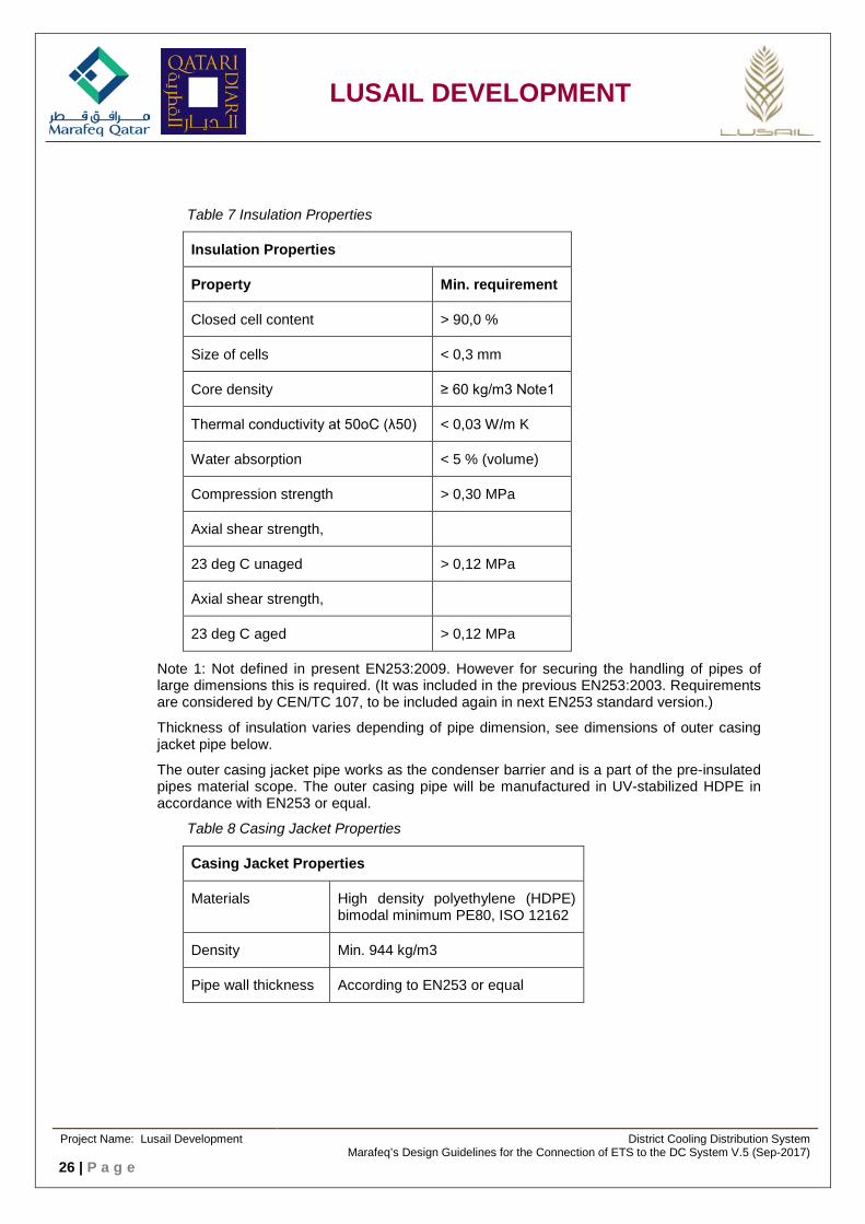
Table 7 Insulation Properties
Insulation Properties
Property Min. requirement
Closed cell content > 90,0 %
Size of cells < 0,3 mm
Core density ≥ 60 kg/m3 Note1
Thermal conductivity at 50oC (λ50) < 0,03 W/m K
Water absorption < 5 % (volume)
Compression strength > 0,30 MPa
Axial shear strength,
23 deg C unaged > 0,12 MPa
Axial shear strength,
23 deg C aged > 0,12 MPa
Note 1: Not defined in present EN253:2009. However for securing the handling of pipes of large dimensions this is required. (It was included in the previous EN253:2003. Requirements are considered by CEN/TC 107, to be included again in next EN253 standard version.)
Thickness of insulation varies depending of pipe dimension, see dimensions of outer casing jacket pipe below.
The outer casing jacket pipe works as the condenser barrier and is a part of the pre-insulated pipes material scope. The outer casing pipe will be manufactured in UV-stabilized HDPE in accordance with EN253 or equal.
Table 8 Casing Jacket Properties
Casing Jacket Properties
Materials High density polyethylene (HDPE) bimodal minimum PE80, ISO 12162
Density Min. 944 kg/m3
Pipe wall thickness According to EN253 or equal
Project Name: Lusail Development District Cooling Distribution System
Marafeq’s Design Guidelines for the Connection of ETS to the DC System V.5 (Sep-2017) 26 | P a g e

LUSAIL DEVELOPMENT
Table 9 Casing Jacket Dimensions
Casing Jacket Dimensions
Dimension
(mm)
Outer diameter casing pipe
Minimum casing wall thickness
DN100 200 mm 3,2
DN125 225 mm 3,4
DN150 250 mm 3,9
DN200 315 mm 4,5
DN250 400 mm 4,8
DN300 450 mm 5,2
DN350 500 mm 5,6
DN400 520 mm 5,7
Surveillance system is NOT required.
The tubular joint casings must be applied before the pipes are welded together.
Joint kits shall be supplied by the pipe material supplier. Joint kit shall include electro welded band joint jacket and a foam kit.
Contractor shall slip on the tubular shell jacket on a pipe next to each joint before welding is carried out.
End caps / seals shall be provided for all pipes during transportation and storage to prevent ingress of moisture and dirt.
Mill test certificates and radiography test certificates, which can be correlated to the pipes and fittings delivered and installed, shall be submitted to the Customer for each consignment of pipes. The Customer shall forward the test certificates to Marafeq. Insulation and jacket test certificates issued by the pre insulated pipe manufacturer shall be submitted to Customer for every consignment of pipes. The Customer shall forward the test certificates to Marafeq.
5.3 Isolation Valves
Main isolation valves (supplied by Marafeq) shall be located directly inside the building as close as possible to the walls. Connection to the district cooling network shall be by welding. Isolation valves must be provided in the supply and return pipe around the heat exchanger(s) to allow for maintenance and cleaning. All isolating valves shall be welded ball valve or welded butterfly valve. Caution is needed so that the seals in the valves will not be damaged during the welding process. All valves shall be easily accessible and tagged. Valves smaller than DN 50 may be welded or threaded ball valve.
Project Name: Lusail Development District Cooling Distribution System
Marafeq’s Design Guidelines for the Connection of ETS to the DC System V.5 (Sep-2017) 27 | P a g e

LUSAIL DEVELOPMENT
5.4 CIP Connection
In order to make CIP (Cleaning in Place) of PHE plates possible, the ETS shall have connections installed. CIP is done without dismounting the PHE. Two ball valves (DN50) for manual air vent and drain shall be provided for each heat exchanger as shown in the P&ID schematic, Appendix 3. These connections will also be used for future chemical injection and periodic flushing (CIP) of each heat exchanger while the isolation valves are closed.
1. Provide hose connection and cap for each valve (air vent and drain).
2. Body, disc and seat rated for a zero leakage shut off at pressure class not less than the heat exchanger(s) design pressure.
3. Provide lever handle with metallic extended stem for insulation.
In order to save CIP chemicals, the water volume shall be reduced to a minimum, and for this the isolating valves should be located close to the PHE.
5.5 Strainers
To protect the heat exchange and control valves from any suspended particles and debris, strainers are required on both inlet nozzles on the heat exchanger (primary and secondary side). The strainer element shall allow for cleaning without being dismantled. The connections shall be flanged or welded.
1. Strainer shall be Y-pattern with blow off drain valve.
2. Screen shall be made of stainless steel with max perforation mesh size 0.6 – 0.8 mm, or as required to protect the PICV and heat exchanger.
3. Screen shall be accessed by way of threaded or bolted cover.
5.6 PLC System
PLC system PLC System shall provide following capabilities: • Modbus 485 RTU communication with BTU calculator for chilled water flow and
temperature • Modbus 485 RTU communication with building automation system (BAS) to monitor the
pump speed, pump status, start/stop, Bypass valve status. PDT, PDS. • Field instrumentation wiring terminations, instrument signal input/output for system,
monitor and control functions, and self-diagnostics. • Data communication between processor and HMI on TCP/Ethernet IP over copper media. • Open network Modbus TCP/IP communication with district cooling plant over copper
media/Fiber optic. • UPS status (Main, Bypass, Trip, Battery low etc.) to be integrated with ETS PLC/HMI.
5.6.1 Human Machine Interface (HMI)
• Graphics display capable of accessing information from process automation controllers for local display and control.
• Graphic display shall be TFT/LCD color touch screen with Ethernet IP over copper media. • Interactive capability to allow operator to control I/O devices and acknowledge alarms
from the graphics display. Operator shall be able to change modes between manual and automatic control and change device states between on and off, enter control setpoints, timer and counter settings, process variables, and loop information by 1 or 2 touch screen operations. The HMI shall be pre-programmed to provide a basic graphical display of the
Project Name: Lusail Development District Cooling Distribution System
Marafeq’s Design Guidelines for the Connection of ETS to the DC System V.5 (Sep-2017) 28 | P a g e

LUSAIL DEVELOPMENT
process. Real-time numeric display of process variables and alarm messages shall be available.
• Security levels shall be accessible by user-defined passwords. Levels shall include engineering configuration of graphic displays and setting system parameters, operator control functions only, and process monitoring only.
• Display size: Nominal 15-inch diagonal.
5.6.2 PLC configuration:
• PLC shall communicate with ETS energy meter calculator to monitor chilled water supply temperature, chilled water return temperature, chilled water flow, and calculated thermal energy usage at ETS.
• PLC shall communicate with the BAS to monitor the pump speed, pump status, start/stop, bypass valve status, PDT on the building chilled water system.
• PLC shall monitor the temperature of the chilled water supply temperature for the building chilled water system.
• Operator selects a setpoint for the building side chilled water supply temperature or building side return temperature or building side delta temperature
• PLC modulates the control valve to control building side chilled water supply temperature or building side return temperature or building side delta temperature
• Should the building side chilled water supply temperature/return temperature/delta temperature building side be above setpoint, the PLC shall move the control valve to a more open position.
• Should the building side chilled water supply temperature/return temperature/delta temperature building side be below setpoint, the PLC shall move the control valve to a more closed position.
• PLC shall monitor the differential pressure across the chilled water supply and chilled water return for each ETS.
• UPS status (Main, Bypass, Trip, Battery low etc.) to be integrated with ETS PLC/HMI. • All process variables shall be communicated from local PLC to district cooling plant
control system utilizing standard open Modbus TCP/IP communication protocol.
5.6.3 Uninterruptible Power Supply (UPS):
Marafeq will supply UPS of 120 minutes battery backup installed within PLC panel which will feed power to programmable logic controller, human machine interface, energy meter, flow meter and panel light.
5.6.4 Project record documents:
• “As built” Panel and General Arrangement diagrams. • “As built” wiring diagrams. • “As built” control system architecture • Technical documents for PLC and Energy meter system.
5.7 Measuring Devices
Measuring devices include instruments and control equipment, flow sensing devices, pressure sensing devices, gauges, electromagnetic flow meters, and energy meters.
Each instrument and control device shall have tag permanently attached with following information, as applicable:
Project Name: Lusail Development District Cooling Distribution System
Marafeq’s Design Guidelines for the Connection of ETS to the DC System V.5 (Sep-2017) 29 | P a g e

LUSAIL DEVELOPMENT
• Tag number. • Manufacturer's name. • Model number. • Serial number. • Operating range. • Calibration setting/range. • Power rating.
5.7.1 General Requirements
Furnish insect proof screens on vents. Furnish new and unused instruments and control devices. Provide mounting accessories, etc. necessary to firmly mount and place device into service.
5.7.2 Instruments and Gauges
1. Resistance Temperature Device (RTD) and or Temperature Transmitter (TT)
• Four-wire platinum nominal 100 ohm. • Spring loaded with 15 mm threaded connection. • 6 mm stainless steel sheath. • Include Type 316 stainless steel reduced bore thermo well with 20 mm threaded
process connection, 75 mm lag extension, 20 mm threaded sensor connection, with insertion length to allow tip to extend past to center of pipe diameter. Immersion length shall be suitably selected as per pipe diameter and manufacturer’s recommendations.
• Each temperature sensor shall be provided with a transmitter, selected to match the sensor, from the same manufacturer.
• Accuracy shall be ±0.1% of full-scale reading and calibrated span. • Transmitter shall be mounted where indicated on approved piping schematic /
design / shop drawings or instrument detail. • Mount transmitter integrally with sensor, pipe mounted or installed in a control
panel, depending on the application, as per the manufacturer’s recommendation. • Distance between sensor and transmitter shall not exceed manufacturer’s
recommendation. • Enclosure shall be stainless steel 316, IP 67, NEMA 4. Connection shall be screw
terminals. • Power supply – 24 V DC loop powered. • Temperature range shall be -20 to 80 ºC.
2. Pressure transmitter
• 4 to 20 mA dc output with local LCD indicator • Carbon steel process flanges and body. • Provide ½” threaded process connections with 2-valve manifold and 50 mm pipe
stand mounting hardware, unless otherwise indicated. • Calibrated span as required for the application. • Diaphragm of Type 316 stainless steel. • Accuracy: ±0.1% of calibrated span. • Design pressure: 1600 kPa maximum. • Design temperature: -20 to 80°C. • Over pressure rating shall be a minimum of 200 percent of operating pressure
limit.
Project Name: Lusail Development District Cooling Distribution System
Marafeq’s Design Guidelines for the Connection of ETS to the DC System V.5 (Sep-2017) 30 | P a g e

LUSAIL DEVELOPMENT
• Transmitter shall be located where shown in the approved schematic / design / shop drawings, mounted integrally with sensor, pipe mounted or installed in control panel.
• Distance between sensor and transmitter shall not exceed manufacturer's recommendation.
• Wetted parts shall be minimum stainless steel 316, electronic enclosure shall be rated for NEMA 4, IP 67.
3. Flow meter
• Flow meters shall be inline electromagnetic type with remote mounted transmitter connecting with Plant SCADA.
• Shall be industrial type, inline electromagnetic type, bidirectional flow meter utilizing Faraday’s law of electromagnetic induction to measure the volume flow rate of water
• Shall be suitable for the medium proposed to be handled by the flow meters. • Body shall be carbon steel, flanges to ANSI/ASME B16.5 class150 for system
design pressure, pipe to Stainless Steel 304 and electrodes of Stainless Steel 316.
• Liner shall be EPDM or equivalent of approved manufacturers recommended. • Bidirectional flow rate measurement capability.
4. Differential pressure transmitter
• Enclosure: IP 65 minimum • 4 to 20 mA dc output with local LCD indicator. • Measuring pressure range: Selected so normal reading is in the middle of the
scale range. • Stainless steel process flanges and body. • Process Connection: 1/2" stainless steel 316L, all wetted parts shall be of
stainless steel 316L with mounting bracket for pipe stand mounting. • 50 mm pipe mounting hardware. • Power supply: Loop powered 24 volts dc. • Calibrated span as required for the application. Supplier shall provide external
provision (Keypad) and HART for span and zero configuration • Diaphragm of Type 316 stainless steel. • Accuracy: +/-0.1% of calibrated span. • Stability: +/-0.25% of upper range for minimum 5 years. • Damping : Adjustable damping with minimum of 0.2 seconds • Over pressure limit: Twice the operating range. • Design temperature: -20 to 80°C. • Provide 1/2" threaded process connections with 3-way valve manifold and 50 mm
pipe stand mounting hardware, unless otherwise indicated.
5. Pressure Gauge
Industrial grade pressure gauges shall be provided. • The pressure gauge shall be bourdon tube type, phenolic or stainless steel case
with plastic lens, black letters on white surface, solid front and blow out back style. 100 mm phenolic case, black on white scale, glycerin filled, Bourdon type gauge with stainless steel movement.
• All units complete with stainless steel block & bleed gauge valves, Ø15mm threaded process connection.
• Scale range: Selected so normal reading is in the middle of the scale range.
Project Name: Lusail Development District Cooling Distribution System
Marafeq’s Design Guidelines for the Connection of ETS to the DC System V.5 (Sep-2017) 31 | P a g e

LUSAIL DEVELOPMENT
6. Temperature Gauge
Industrial grade thermometers shall be provided in the supply and return line of each heat exchanger on both the primary and building side.
• Thermometers shall be bi-metal type thermometers with 125 mm diameter stainless steel dial and shatter proof glass, black letters on white surface, external pointer adjustment and rear angle adjustable with connection to thermo well.
• Temperature range shall be suitable for chilled water supply and return temperatures and the scale shall be in °C. The indicator shall be suitable for operating water temperatures specified and ambient temperature of up to 50 °C.
• Scale Range: Selected so normal reading is in the middle of the scale range. • 15 mm adjustable “every angle” stainless steel bottom connection, stainless steel
welded construction sheath to suit thermo well. • Thermo wells shall be 316 stainless steel bar stock construction, step type. • The Thermo well shall protrude 1/2 pipe diameter inside the pipe and lagging
extension suitable for the insulated pipe.
5.7.3 Instrument Wiring
1. Analog signal cable:
• Configuration: Twisted pair, shielded, and jacketed. • Insulation: 300-volt, 15 mil, 90ºC, PVC, color-coded to permit identification of
each conductor. • Conductors: 1.0 square mm, 7 strand copper, Class B. • Shield: Tinned copper braid providing 100% coverage against noise together
with 0.05 mm2 stranded tinned drain wire.
2. Power wire:
• Rating: 600-volt, 90ºC, PVC insulation/jacket. • Conductors: 2.5 square mm stranded copper.
3. Discrete signal wire:
• Rating: 600-volt, 90ºC, PVC insulation/jacket. • Conductors: 1.5 square mm, stranded copper. • Conductors shall be continuous between devices. Splices are not acceptable. • Conductors shall be terminated with pressure type, pre-insulated, flanged,
slotted, tongue, indenter lugs. Soldered terminators are not acceptable.
5.7.4 Cable Identification
Identify each cable with plastic tags permanently affixed to cable. Attach tags to each cable at each termination and wherever cable is accessible in junction or pull boxes. Provide tags with printer-printed circuit number. Provide 3-phase power cables with tag with printer-printed cable number affixed to each phase conductor.
Tag colors: • Power cables: Red tags. • Analog and discrete signal cables: Yellow tags.
Project Name: Lusail Development District Cooling Distribution System
Marafeq’s Design Guidelines for the Connection of ETS to the DC System V.5 (Sep-2017) 32 | P a g e

LUSAIL DEVELOPMENT
5.7.5 Installation - General
• Install instrument and control devices in accordance with manufacturer's recommendations and/or where approved by Marafeq Qatar.
• Mount instruments to be rigidly supported, level and plumb, and in such a manner as to provide accessibility; protection from damage; isolation from heat, shock and vibration; and freedom from interference with other equipment, piping, and electrical work.
• To avoid damage, do not install instruments until heavy construction work adjacent to instruments has been completed.
• Instrumentation mounted outdoors shall be housed in insulated/heated housings to maintain operational temperature limits.
• Maximum convenience in operation and servicing of instrument. Orient connections so instruments or piping will not obstruct aisles, platforms, or ladders. Transmitters shall be visible and accessible for maintenance.
• Install field-mounted instruments so they are accessible from grade, platform, or permanent ladder. Instruments requiring adjustment or inspection shall be accessible for servicing from grade, walkway, platform, or permanent ladder.
• All valves shall be accessible from grade or platforms. Use manufacturer’s recommended clearance distances.
• Mount local indicators, recorders, and controllers so they are readable, controllable, and serviceable from grade or platforms.
5.8 Vent and Drain Valves
Other than the 50 mm CIP/manual vent valves at the heat exchangers, all other vent valves shall be DN 15 installed on the highest point in the direction of flow of the district cooling pipes. Bleeds shall be provided for manual extraction of air from the system. The bleeds shall be fitted with valves and end caps located 400 mm above floor. Automatic air vents shall be provided at all venting locations. Other than the 50 mm CIP/drain valves at the heat exchangers, all other drain valves shall be DN 15 installed at the lowest point of the pipes. The bleeds shall be fitted with end caps.
5.9 Connection with the District Cooling Network
Generally, the district cooling tie-in point is extended one meter inside the plot boundary; however, the Customer shall obtain tie-in point information (coordinates and levels) from LREDC and verify them at site. Any piling works for the basement construction adjacent to the infrastructure district cooling tie-in point shall be protected by the Customer to ensure that the existing infrastructure district cooling pipe is not damaged.
5.10 Jointing
Works on the primary district cooling side shall be carried out by the company with welding license and certified welders who carried out the approved welder qualification test in accordance with EN287-1 or passed brazing tests according to Qualification on Copper pipes as with BS 1724 or equal.
Installation of valves in primary district cooling system must use a welding method that will not cause damage to the valve seal. Therefore it requires electric fusion welding if the weld is located at shorter distances than 0.5 m away from the valve house. In addition the valve supplier’s recommendations shall be followed.
Project Name: Lusail Development District Cooling Distribution System
Marafeq’s Design Guidelines for the Connection of ETS to the DC System V.5 (Sep-2017) 33 | P a g e

LUSAIL DEVELOPMENT
Before connecting to the district cooling network, the Customer shall submit a method statement to Marafeq for approval.
5.11 Insulation
Insulation shall be of closed cell elastomeric/cellular rubber which is glued together, edge to edge. Insulation thicknesses for all pipe sizes shall be not less than 50 mm (2 inch). The chilled water piping systems and pumps shall be insulated and jacketed with aluminium insulation jacketing. The contractor shall clad all insulated pipe work and duct work with aluminium hammer finish sheets ASTMB209 and ASTMB209M with a minimum thickness of 1.0mm.
For gasketed PHEs, the PHE manufacturer shall provide removable insulation jackets and, under the heat exchangers, drip trays. For brazed plate heat exchangers, insulation may be installed in the field and drip trays are not required.
Use closed cell elastomeric; expanded, flexible, molded to pipe size and conforming to ASTM C534, and ASTM C177 or ASTM C518 latest editions. Insulation material shall be manufactured without the use of CFC’s, HFC’s or HCFC’s. It shall also be formaldehyde free, low VOC’s, fiber free, dust free and resists mold and mildew.
Density shall be not less than 68 kg/m3.
Thermal conductivity shall not exceed 0.035 W/m-K at 23.9 0C (75 0F) mean temperature (0.27 Btu-in/h-ft2-0F) when tested in accordance with ASTM C 177 or ASTM C 518, latest revisions.
Flame/smoke spread rating of 25/50 tested by ASTM E84-91A.
Maximum water vapour transmission of 1.16x10⁻⁶ Kg/s-m-Pa (0.8 perm-inches).
For piping up to 150 mm (6 inch); tubular or pre-slit with pre-glued longitudinal seams. For larger piping and ductwork, flat sheets.
Use suitable jacketing material for anti-sweat conditions. The vapour barrier must be kept tight at all joints. Seal transition area between different insulation materials carefully. Thermometers, etc., shall have an insulating cap.
Provide shields between insulation and the supports. Use a heavy density insulating material as an insert between piping and shield so the insulation is not crushed by the weight of the pipe. All piping shall be suitably identified as to the media contained. Any chilled water piping installed on the exterior of a building shall have insulation thickness doubled and jacketed entirely in aluminium.
Insulation work shall be carried out by a contractor who has experience installing thermal insulation.
5.12 Tagging
Pipes, valves and equipment shall be tagged according BS 1710 or equal.
Each item of equipment shall be identified by using white non-corroding shatterproof laminated plastic labels engraved with black letters, 6mm high, the function and number of each piece of equipment, i.e. primary chilled water pump, pump numbers, etc. All labels shall be fixed with screwed, riveted or glued to equipment cover. Where a piece of equipment is insulated the identification label shall be fixed to the external surface of the insulation.
Valves shall be tagged with identification discs attached with a split ring, S-hook or brass chain, whichever is the most appropriate. All primary and secondary chilled water pipe work shall have self-coloured, self-adhesive PVC tape bands colour coded in accordance with BS 1710 so far as this is applicable and at suitable intervals.
Project Name: Lusail Development District Cooling Distribution System
Marafeq’s Design Guidelines for the Connection of ETS to the DC System V.5 (Sep-2017) 34 | P a g e
LUSAIL DEVELOPMENT
5.13 Changes to the System
Once the design has been approved, the Customer shall not change or replace any equipment during the installation without informing Marafeq. Any future changes to the building's cooling water system that will impact the district cooling system must be reported to and, when appropriate, reviewed by Marafeq.
The Customer is responsible for maintaining his secondary side system so that it continues to perform as intended.
If warranted by changes in temperatures and flow conditions, the Customer should verify that his side of the ETS is properly balanced.
6 APPENDICES
Appendix 1: Design Conformance Certificate (Refer document number LUS-CPALL-MAQ-PRC-
UT-10560 Utility Application Procedure for District Cooling, Application No. 2)
Appendix 2: ETS Conformance Certificate
Appendix 3.1: Schematic of ETS installation for Single Heat Exchanger
Appendix 3.2: Schematic of ETS installation for Multiple Heat Exchangers
Appendix 4.1: Compliance statement: Method statement for Installation, Testing and Commissioning of
Equipment inside ETS (Primary side)
Appendix 4.2: Compliance statement: Method statement for Hydro static test (Primary side)
Appendix 4.3: Compliance statement: Method statement for Flushing/Pipe conditioning (Primary side)
Notes: Appendix 2 Submitted for “ETS Conformance Certificate” after testing and commissioning of ETS. Appendices 3.1 and 3.2 shall be used as guideline for specific ETS design. Appendices 4.1, 4.2 and 4.3 shall be submitted as a part of method statement submittals.
Project Name: Lusail Development District Cooling Distribution System
Marafeq’s Design Guidelines for the Connection of ETS to the DC System V.5 (Sep-2017) 35 | P a g e
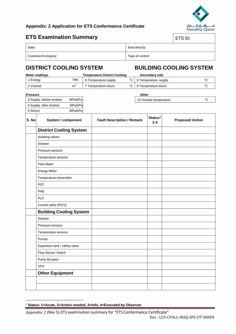
Appendix: 2 Application for ETS Conformance Certificate
ETS Examination Summary ETS ID:
Date: Executed by:
Customer/Company: Type of control:
DISTRICT COOLING SYSTEM BUILDING COOLING SYSTEM Meter readings Temperature District Cooling Secondary side
1 Energy TRh 6 Temperature supply oC 8 Temperature supply oC
2 Volume m3 7 Temperature return oC 9 Temperature return oC
Pressure Other
3 Supply, before strainer MPa/kPa 10 Outside temperature oC 4 Supply, after strainer MPa/kPa
5 Return MPa/kPa
S. No System / component Fault Description / Remark Status1 1‐4 Proposed Action
District Cooling System Isolating valves
Strainer Pressure sensors Temperature sensors Flow Meter Energy Meter Temperature transmitter PDT PHE PLC Control valve (PICV)
Building Cooling System Strainer
Pressure sensors Temperature sensors Pumps Expansion tank / safety valve Flow Sensor Switch Pump By-pass VFD
Other Equipment
1 Status: 1=Acute, 2=Action needed, 3=Info, 4=Executed by Observer
Appendix: 2 (Rev 5) ETS examination summary for “ETS Conformance Certificate” Doc : LUS-CPALL-MAQ-SPE-UT-00004

NOTES:LEGENDS:
OPTION 2 - MAIN ISOLATION VALVE (INSIDE)
WHEN LOCATED INSIDE, EMERGENCY CONNECTIONS SHALL BE ACCESSIBLE
FROM OUTSIDE AT GRADE LEVEL
ENERGY METER PLC CONTROLLER
PLANT (DCP)
DISTRICT COOLING
CUSTOMER
TELECOM
ROOM
OPTION 1 - MAIN ISOLATION VALVE (OUTSIDE)
WHEN LOCATED OUTSIDE, VALVES SHALL BE PRE-INSULATED WELDED
BALL VALVES AND EMERGENCY CONNECTIONS SHALL BE ACCESSIBLE AT GRADE LEVEL
FLOW METER RUN
METER RUN WITHOUT ANY FLOW DISTURBANCES
DRAWING TITLE:
DATE:DRAWING NO.
ETS-GENERAL DISTRICT COOLING PIPING AND
INSTRUMENTATION DIAGRAM
FOR SINGLE HEAT EXCHANGERS
LUS-CPALL-MAQ-DWG-UT-10601 10-SEP-17
APPENDIX 3.1
CAD Ref: Q:\Projects\Lusail Development\Project Guidelines & Technical Requirements\Sub-developers\DC\ETS Layout drawing DWG format\ LUS-CPALL-MAQ-DWG-UT-10600-601_1.dwg Last saved: Wed, 30 Aug 2017 02:37 pm Plotted By : anthoven.calma

ENERGY METER PLC CONTROLLER
NOTES:LEGENDS:
PLANT (DCP)
DISTRICT COOLING
CUSTOMER
TELECOM
ROOM
OPTION 1 - MAIN ISOLATION VALVE (OUTSIDE)
WHEN LOCATED OUTSIDE, VALVES SHALL BE PRE-INSULATED WELDED
BALL VALVES AND EMERGENCY CONNECTIONS SHALL BE ACCESSIBLE AT GRADE LEVEL
OPTION 2 - MAIN ISOLATION VALVE (INSIDE)
WHEN LOCATED INSIDE, EMERGENCY CONNECTIONS SHALL BE ACCESSIBLE
FROM OUTSIDE AT GRADE LEVEL
FLOW METER RUN
METER RUN WITHOUT ANY FLOW DISTURBANCES
DRAWING TITLE:
DATE:DRAWING NO.
ETS-GENERAL DISTRICT COOLING PIPING AND
INSTRUMENTATION DIAGRAM
FOR MULTIPLE HEAT EXCHANGERS
LUS-CPALL-MAQ-DWG-UT-10600 10-SEP-17
APPENDIX 3.2
CAD Ref: Q:\Projects\Lusail Development\Project Guidelines & Technical Requirements\Sub-developers\DC\ETS Layout drawing DWG format\ LUS-CPALL-MAQ-DWG-UT-10600-601_1.dwg Last saved: Wed, 30 Aug 2017 02:36 pm Plotted By : anthoven.calma

Appendix: 4.1
Marafeq Technical Requirements for the connection of ETS(s) to the District Cooling System Compliance Statement: Method Statement for Installation, Testing and Commissioning of equipment
inside ETS (Primary side)
S. No. Description Status A Documentation requirements
1
The following documents shall be submitted to Marafeq for review and approval. Upon approval contractor may proceed for commissioning with due notice to Marafeq where applicable:
Compliance sheet for installation, testing and commissioning (this document)
Vendor approved installation, testing and commissioning procedures for each material mentioned in section-B of this document.
Installation, testing and commissioning template sheet
B Material
1
Heat exchanger Pre-insulated pipe PICV (Pressure Independent Control Valve) Strainer Ball valve Instruments (Pressure gauge, pressure differential transmitter,
temperature gauge, temperature transmitter, flow meter, Energy meter )
PLC
Installation/Testing/Commissioning/Calibration C Heat Exchanger
1 Ensure that the material is received, inspected and stored in good condition
2 Ensure that material shall be installed as per manufacturer installation recommendation/procedure
3 Ensure that the material shall be tested/ commissioned/calibrated as per manufacturer recommendation/procedure
4 Ensure that the installation, testing/commissioning/calibration record sheet duly filled shall be available for Marafeq signature/acceptance
D Pre-insulated pipe
1 Ensure that the material is received, inspected and stored in good condition
2 Ensure that material shall be installed as per manufacturer installation recommendation/procedure
3 Ensure that the material shall be tested/ commissioned/calibrated as per manufacturer recommendation/procedure
4 Ensure that the installation, testing/commissioning/calibration record sheet duly filled shall be available for Marafeq signature/acceptance
E PICV
1 Ensure that the material is received, inspected and stored in good condition
Appendix: 4.1 Rev 5 Compliance statement: Method statement for Installation, Testing and Commissioning of Equipment inside ETS (Primary side) Doc :LUS-CPALL-MAQ-SPE-UT-00004 Page 1 of 2

Appendix: 4.1
S. No. Description Status
2 Ensure that material shall be installed as per manufacturer installation recommendation/procedure
3 Ensure that the material shall be tested/ commissioned/calibrated as per manufacturer recommendation/procedure
4 Ensure that the installation, testing/commissioning/calibration record sheet duly filled shall be available for Marafeq signature/acceptance
F Strainer
1 Ensure that the material is received, inspected and stored in good condition
2 Ensure that material shall be installed as per manufacturer installation recommendation/procedure
3 Ensure that the material shall be tested/ commissioned/calibrated as per manufacturer recommendation/procedure
4 Ensure that the installation, testing/commissioning/calibration record sheet duly filled shall be available for Marafeq signature/acceptance
G Ball Valve 1 Ensure that the material is received, inspected and stored in good
condition
2 Ensure that material shall be installed as per manufacturer installation recommendation/procedure
3 Ensure that the material shall be tested/ commissioned/calibrated as per manufacturer recommendation/procedure
4 Ensure that the installation, testing/commissioning/calibration record sheet duly filled shall be available for Marafeq signature/acceptance
H Instruments (Pressure gauge, pressure differential transmitter, temperature gauge, temperature transmitter, flow meter, relief valve)
1 Ensure that the material is received, inspected and stored in good condition
2 Ensure that material shall be installed as per manufacturer installation recommendation/procedure
3 Ensure that the material shall be tested/ commissioned/calibrated as per manufacturer recommendation/procedure
4 Ensure that the installation, testing/commissioning/calibration record sheet duly filled shall be available for Marafeq signature/acceptance
Signature and Stamp of Consultant Signature and Stamp of Contractor/Supplier
Date: Date:
Appendix: 4.1 Rev 5 Compliance statement: Method statement for Installation, Testing and Commissioning of Equipment inside ETS (Primary side) Doc :LUS-CPALL-MAQ-SPE-UT-00004 Page 2 of 2
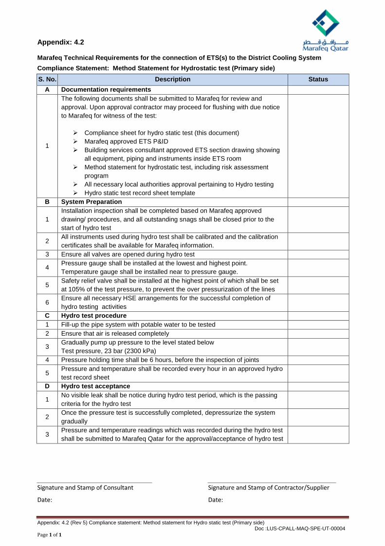
Appendix: 4.2
Marafeq Technical Requirements for the connection of ETS(s) to the District Cooling System Compliance Statement: Method Statement for Hydrostatic test (Primary side) S. No. Description Status
A Documentation requirements
1
The following documents shall be submitted to Marafeq for review and approval. Upon approval contractor may proceed for flushing with due notice to Marafeq for witness of the test:
Compliance sheet for hydro static test (this document) Marafeq approved ETS P&ID Building services consultant approved ETS section drawing showing
all equipment, piping and instruments inside ETS room Method statement for hydrostatic test, including risk assessment
program All necessary local authorities approval pertaining to Hydro testing Hydro static test record sheet template
B System Preparation
1 Installation inspection shall be completed based on Marafeq approved drawing/ procedures, and all outstanding snags shall be closed prior to the start of hydro test
2 All instruments used during hydro test shall be calibrated and the calibration certificates shall be available for Marafeq information.
3 Ensure all valves are opened during hydro test 4 Pressure gauge shall be installed at the lowest and highest point.
Temperature gauge shall be installed near to pressure gauge.
5 Safety relief valve shall be installed at the highest point of which shall be set at 105% of the test pressure, to prevent the over pressurization of the lines
6 Ensure all necessary HSE arrangements for the successful completion of hydro testing activities
C Hydro test procedure 1 Fill-up the pipe system with potable water to be tested 2 Ensure that air is released completely
3 Gradually pump up pressure to the level stated below Test pressure, 23 bar (2300 kPa)
4 Pressure holding time shall be 6 hours, before the inspection of joints
5 Pressure and temperature shall be recorded every hour in an approved hydro test record sheet
D Hydro test acceptance
1 No visible leak shall be notice during hydro test period, which is the passing criteria for the hydro test
2 Once the pressure test is successfully completed, depressurize the system gradually
3 Pressure and temperature readings which was recorded during the hydro test shall be submitted to Marafeq Qatar for the approval/acceptance of hydro test
Signature and Stamp of Consultant Signature and Stamp of Contractor/Supplier
Date: Date:
Appendix: 4.2 (Rev 5) Compliance statement: Method statement for Hydro static test (Primary side) Doc :LUS-CPALL-MAQ-SPE-UT-00004 Page 1 of 1

Appendix: 4.3
Marafeq Technical Requirements for the connection of ETS(s) to the District Cooling System Compliance Statement: Method Statement for Flushing/Pipe conditioning (Primary side) S. No. Description Status
A Documentation requirements
1
The following documents shall be submitted to Marafeq for review and approval. Upon approval contractor may proceed for flushing with due notice to Marafeq for witness of the test:
Compliance sheet for flushing (this document) Method of statement for flushing/pipe conditioning including risk
assessment program. (BSRIA application guide AC 1/2001.1 shall be used as the reference guide.)
All necessary local authorities approval pertaining to flushing/pipe conditioning activities
Flushing/pipe conditioning record sheet template for each stage
B System Preparation
1 All equipment, bypasses, drain and vent shall be installed as per the approved method statement for flushing
2 Ensure that all utilities/consumables (including but not limited to potable water, fuel, chemicals, filters etc. ) are available at site to proceed for flushing
3 Critical drain points shall be connected to the nearest drain pit to facilitate emergency draining if situation demands
4 Flow meter shall be available at site to monitor the velocity of flushing activity in line with approved method of statement
5 Pressure gauge shall be installed at the lowest and highest point. Temperature gauge shall be installed near to pressure gauge.
6 All instruments used during flushing shall be calibrated and the calibration certificates shall be available for Marafeq information.
7 Water treatment specialist shall be available at site to monitor the progress of flushing activities
8 Ensure all necessary HSE arrangements for the successful completion of flushing/pipe conditioning activities
9 Marafeq will inspect the system readiness, and accordingly will release the “request to proceed” submitted by the flushing contractor
C Flushing Procedure
1
The whole flushing/pipe conditioning process generally falls under the following stages:
Flushing Chemical cleaning Passivation
2 Flushing shall start within 48 hours of the hydrostatic test; otherwise preventive measures shall be taken to avoid corrosion.
3 Top up the system completely with potable water and release the air 4 Start the pump at low speed and vent the air out of the system completely
5 Gradually increase the speed of the pump to meet with sufficient flushing velocity
Appendix: 4.3 Rev 5 Compliance statement: Method statement for Flushing/Pipe conditioning (Primary side) Doc :LUS-CPALL-MAQ-SPE-UT-00004 Page 1 of 2

Appendix: 4.3
S. No. Description Status
6 Follow the procedure as mentioned in the approved method of statement for flushing/pipe conditioning
7 After final passivation is achieved , the system shall be preserved in line with passivation water quality
D Flushing /Pipe conditioning acceptance
1 Each stage of flushing/pipe conditioning shall be approved by Marafeq before proceeding to next stage
Sampling at each stage shall be witnessed by Marafeq
2
Final passivation water quality shall be as per the below chart:
Parameters Unit Standard pH -- 8.5 to 10.5 Total dissolved solids ppm < 2000 Conductivity µSiemens/cm < 3000 Total iron as Fe ppm < 1.0 Nitrite as NaNO2 ppm > 800 Total Suspended Solids ppm < 20 Chlorides as Cl— ppm < 150 Total Alkalinity as CaCO3 ppm < 250 Total Calcium hardness as CaCO3 ppm < 100
3 Water analysis result based on the above parameters shall be recorded in passivation record sheet and shall be submitted to Marafeq for final acceptance along with the water treatment specialist water analysis report
4 Tie in with the other adjoining system shall be executed (wherever applicable)
Signature and Stamp of Consultant Signature and Stamp of Contractor/Supplier
Date: Date:
Appendix: 4.3 Rev 5 Compliance statement: Method statement for Flushing/Pipe conditioning (Primary side) Doc :LUS-CPALL-MAQ-SPE-UT-00004 Page 2 of 2