marco - ecocranesecocranes.hu/uploads/marco_mlu010080-d2-25-gb.pdf · marco dokumentation •...
TRANSCRIPT

Marco Dokumentation • Documentation
•Orderspecifikation •Drift och skötselinstruktion Order Specification Operating and Maintenance Instructions Aufragsspezifikation Betriebs- und Wartungsanleitung Spécification de commande Instructions de marche et d'entretien Especificación de pedido Instrucciones de operación y mantenimiento •Garantivilkor •Teknisk beskrivning med reservdelsnummer Guarantee Conditions Technical Descriptions with Spare Parts Numbers Garantiebedingungen Technische Berchreibung mit Ersatzteilnummern Conditions de garanie Description technique avec refernces des piéces détachées Condiciones de garantía Descripción técnica con nº de piezas de repuesto •Elschema •Hydraulschema Electric ciruit Hydraulic Circuit Schaltplan Hydraulikplan Schéme électrique Schéma hydraulique Esquema eléctrico Esquema hidráulico •EG-försäkran •Tilläggsutrustning Declaration of Conformity Addational Equipment EG-Konformitätserklärung Zusätzliche Ausrüstung Certificat de Conformité Èquipment Complémentarie Declaración de Conformidad Equipamiento complementario

Table of content
1. Orderspecification. (1 page) 2. Operating and maintenance instructions. (5 pages) 3. CE declaration. (1 page) 4. Technical description scissors. (1 page) 5. Technical description safety frame. (1 page) 6. Tecnical description electrical system. (1 page) 7. Technical description hydraulic system. (1 page) 8. Electric circuit. (1 page) 9. Hydraulic circuit. (1 page)

ORDER SPECIFICATION LIFT TABLE MLU
MACHINE DATA: EL-DATA: Mfg. No.: Motor Voltage: 3*400V 50Hz Type: MLU010080-D2-25 Control Voltage: 24V Lifting Capacity 1000 Kg Motor Power: 0,72kW 20% ED Fixed weight 220 Kg El-Diagram No: 306545e Delivery Date: Hydraulic circuit: 406027b Marco Order No: Order No: LOAD DISTRIBUTION AND APPLICATION: X Normal use, Uniformly Distributed loads, e.g. handling of the goods on a pallet or similar load carrier. Acceptable Load Distribution: Max. cantilevered load in % of Lifting 50 % 33 1/3 % 100% Capacity (above) Other application or Load Distribution: Application:......................................................................................................... .......................................................................................................... Load Distribution in % of Lifting Capacity .....-......% ......-......%. .........-...%. Max. axle load , kg.......-..... Max wheel load, kg......-......... Point loads ...................-....................................................................................... Protection Class: Motor IP 55 Control system IP 65 Max. noise pressure does not exceed 75 dB(A). Transportation of persons on the Lift Table is NOT allowed. SEE ENCLOSED STANDARD INSTRUCTION MANUAL FOR ADVICES ABOUT THE PROPER OPERATION, MAINTANANCE AND SPARE PARTS.

1/5
Operating and Maintenance
Instructions for MARCO Lift Tables IMPORTANT! Study this manual now! It is a guide to the use of your lift table and it is important that the personnel who use this equipment should be familiar with this manuals content when the lift table is installed. This will ensure that correct operation and maintenance are observed from the outset.
DELIVERY INSPECTION Check first that the lift table has not suffered any damage during transport or unloading. Should any damage have been sustained, a claim should be lodged with the carriers and the lift table should not be put into operation until advice is sought from MARCO. WARRANTY The warranty conditions are stated on the warranty document enclosed. RECOMMENDED SPARE PARTS We normally carry complete stocks of spare parts for standard lift tables. Depending on the operating conditions it is also advisable to carry certain parts in stock on site. These are shown in bold letters in the spare parts list. Certain items are not usually supplied as spare parts, but have been included in the list for reference purposes. RETURN OF SPARE PARTS
Do not return any parts to us that have been worn out by normal use or accidentally damaged. Parts should only be returned when the defect falls under the warranty conditions. In such cases the goods should be returned immediately the fault is detected, to ensure the right to free replacement. MARCO AB Box 1080 SE-262 21 ÄNGELHOLM Tel: + 46(0)431-44 93 00 Fax: + 46(0)431-830 42
2/5
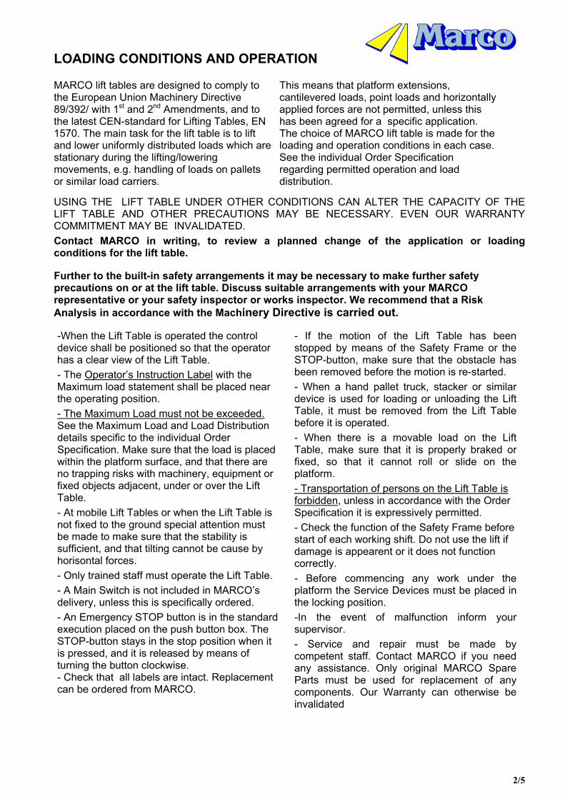
LOADING CONDITIONS AND OPERATION MARCO lift tables are designed to comply to the European Union Machinery Directive 89/392/ with 1st and 2nd Amendments, and to the latest CEN-standard for Lifting Tables, EN 1570. The main task for the lift table is to lift and lower uniformly distributed loads which are stationary during the lifting/lowering movements, e.g. handling of loads on pallets or similar load carriers.
This means that platform extensions, cantilevered loads, point loads and horizontally applied forces are not permitted, unless this has been agreed for a specific application. The choice of MARCO lift table is made for the loading and operation conditions in each case. See the individual Order Specification regarding permitted operation and load distribution.
USING THE LIFT TABLE UNDER OTHER CONDITIONS CAN ALTER THE CAPACITY OF THE LIFT TABLE AND OTHER PRECAUTIONS MAY BE NECESSARY. EVEN OUR WARRANTY COMMITMENT MAY BE INVALIDATED. Contact MARCO in writing, to review a planned change of the application or loading conditions for the lift table. Further to the built-in safety arrangements it may be necessary to make further safety precautions on or at the lift table. Discuss suitable arrangements with your MARCO representative or your safety inspector or works inspector. We recommend that a Risk Analysis in accordance with the Machinery Directive is carried out. -When the Lift Table is operated the control device shall be positioned so that the operator has a clear view of the Lift Table. - The Operator’s Instruction Label with the Maximum load statement shall be placed near the operating position. - The Maximum Load must not be exceeded. See the Maximum Load and Load Distribution details specific to the individual Order Specification. Make sure that the load is placed within the platform surface, and that there are no trapping risks with machinery, equipment or fixed objects adjacent, under or over the Lift Table. - At mobile Lift Tables or when the Lift Table is not fixed to the ground special attention must be made to make sure that the stability is sufficient, and that tilting cannot be cause by horisontal forces. - Only trained staff must operate the Lift Table. - A Main Switch is not included in MARCO’s delivery, unless this is specifically ordered. - An Emergency STOP button is in the standard execution placed on the push button box. The STOP-button stays in the stop position when it is pressed, and it is released by means of turning the button clockwise. - Check that all labels are intact. Replacement can be ordered from MARCO.
- If the motion of the Lift Table has been stopped by means of the Safety Frame or the STOP-button, make sure that the obstacle has been removed before the motion is re-started. - When a hand pallet truck, stacker or similar device is used for loading or unloading the Lift Table, it must be removed from the Lift Table before it is operated. - When there is a movable load on the Lift Table, make sure that it is properly braked or fixed, so that it cannot roll or slide on the platform. - Transportation of persons on the Lift Table is forbidden, unless in accordance with the Order Specification it is expressively permitted. - Check the function of the Safety Frame before start of each working shift. Do not use the lift if damage is appearent or it does not function correctly. - Before commencing any work under the platform the Service Devices must be placed in the locking position. -In the event of malfunction inform your supervisor. - Service and repair must be made by competent staff. Contact MARCO if you need any assistance. Only original MARCO Spare Parts must be used for replacement of any components. Our Warranty can otherwise be invalidated

3/5
INSTALLATION NOTE! AT ALL WORK UNDER THE PLATFORM THE SERVICE DEVICES SHALL BE IN BLOCKING POSITION! Check that the Lift Table has not been damaged during transportation. If so, report this to the transport company and to MARCO. 1. In order to facilitate the handling of the Lift Table during installation, Lifting Eye Bolts are included in the delivery. Fit the lifting eye bolts. Handle the Lift Table by means of lifting and transport devices with sufficient capacity. The Lift Table must not be lifted only at the arm attachment end of the platform.
2. If the Lift Table is be installed in a pit or directly on the ground it must be placed on a firm levelled foundation, e.g. a smooth concrete floor. The base frame is normally not self-supporting and must therefore be fully supported. 3. The Lift Table must be fixed to the ground to prevent unintentional movement when pushed by a stacker etc. Lift tables with larger platform surfaces than standard, or when off-centred loads or horizontal forces are applied, it is also necessary to fix the Lift Table to the ground to ensure full stability. In the base frame there are holes available, for attachment by means of for example expanding bolts. See also the Installation Drawing for the actual Lift type. If goods shall be transferred on or off the Lift Table in raised position, the Lift Table shall be positioned so that this is made over the arm attachment end. Check that there is no risk to tilt up the platform unintentionally. If necessary an anti-tilt arrangement can be added (accessory).
4. If the Lift Table is installed in a pit, this shall be executed in accordance with the Installation Drawing. When applicable arrange drainage from the pit. 5. The MARCO AX Lift Table is provided with a built-in hydraulic power pack, or as option with a separate power unit.
Connect the Hydraulic Hose, which is packed together with the separate Power Unit, to the Lift Table. Alternatively the hydraulic connection is made with fixed installed Hydraulic Pipes. If the Lift Table is to be installed in a pit, a provisional connection of the hose is made before the Table is placed into the pit. When the Lift Table has been placed into the pit the final connection should then be made. The cable(s) from the Lift Table shall be connected to the correct junctions in the Relay Box, in accordance with the wiring diagram.
6. The Push Button Box, which is connected to the Relay Box, or at single phase operation to a
junction box, by a 3 m long cable, must be placed so that the operator has a clear view of the Lift Table during operation.
7. Connect a 3-Phase electric cable with an earth wire, of suitable size in comparison to the motor current, to the Mains Junctions in the Relay Box. A Neutral line is not necessary Single phase operated tables do usually not have any Main Switch, but the electric plug is used for disconnecting the mains feed.. Check that the voltage setting in the relay box complies to the mains voltage. If optional Limit Switches or other electric accessories are included, connect these in accordance with the actual wiring diagram. The supply lines shall be provided with main fuses and a mains switch (not supplied by MARCO).
Note! The electric connections must be carried out by a qualified electrician.
8. Usually the power pack is delivered with the necessary hydraulic oil, ISO 32, in the tank. Otherwise the hydraulic oil which is supplied in separate bottles must be used to fill theoil tank. Remove the Lifting Eye Bolts from the Lift Table and save these for future use. 9. The Lift Table can now be operated (push the UP-button). Two phases may need to be changed to achieve correct rotation direction. See marking arrow on the motor. 10. The table is raised to top position by pressing the UP-button. Apply the Service Devices to prevent lowering. 11. Make holes in the ground for the Attachment Bolt fixing hole positions and fix these. 12. The Lift Table is now ready for operation. Check the operation of the Safety Frame at lowering by means of pressing this. The lowering movement shall stop prior to that an object is trapped by the platform safety frame. In order to be able to continue the lowering the UP-button has to be pressed shortly to release the object (‘reset function’). Thereafter the lowering movement can continue, by pressing the DOWN-button.
If the Lift Table is moved to another operation site it must be checked carefully before it is taken into operation, to ensure that no damages have occured during transport and installation.

4/5
MAINTENANCE OF MARCO LIFT TABLES Inspections shall be carried out approx. once per month, unless the operating conditions and the environment require shorter intervals. Inspections or work under the platform shall only be carried out with the maintenance devices deployed. The function of the Safety Frame must be checked at start of each working shift. HYDRAULIC SYSTEM
MECHANICAL CONSTRUCTION
ELECTRIC EQUIPMENT
1.1 Check the oil tank for possible leakage. 1.2 Check the oil level in the tank by means of the oilstick in the tank lid. Re-fill if necessary. Oil type ISO 32, if nothing else is specified on the Power Pack. If the oil is dirty it must be replaced. 1.3 Inspect the hydraulic tubes and connections for leakage or damage. Correct if necessary. 1.4 Inspect cylinders, hydraulic hoses and fittings for damage or wear. 1.5 Change the oil after one year. Then change the oil every 5th year (preven- tive maintenance)
2.1 Check that all wheels and bearing pins are properly secured. 2.2 Check that there is no excessive bearing play. 2.3 Check that that there are no breaks or cracks in the welded joints. 2.4 Check that the safety frame profiles and the attachment details are intact and not damaged 2.5 Check that the fixations to the ground (if applicable) are firm.
3.1 Inspect and test the electric functions are correct. 3.2 Check that there are no loose or trapped cables and wires. Adjust if necessary. 3.3 Check the setting of the motor protection relay.
FAULT TRACING Fault tracing shall be made by competent staff. Contact MARCO if assistance is desired or if the fault cannot be found through the actions below. APPLY THE SERVICE DEVICES AT THE LOWER ARM WHEELS AT INSPECTIONS AND WORK UNDER THE PLATFORM. FAULT REASON ACTION The motor does not start The mains switch is in OFF-position.
No mains feed. The STOP-button is pressed. Primary or secondary line fuses activated
Turn the switch to ON. Check the mains supply. Turn the button clockwise to release. Check the reason and reset.
No lifting movement Wrong motor rotation direction. Incorrect electric connection. The relief valve opens. The motor stops due to motor protection relay actuated. Other reason
Shift two phases. Check the connections. Table overloaded - Remove the excessive load. Motor protection relay not correctly set - adjust. Contact MARCO
The lift table does not reach the top position.
Insufficient oil volume. The relief valve opens.
Add oil , but not more than required to reach the top level. Too much oil may cause an overfull oil tank when the Lift lowers. Table overloaded - Remove the excessive load.
Jerky lifting or lowering movement
Air in the hydraulic system. Check the oil level. Operate the table a few times at approx. 5 min intervals. When table is at bottom level keep pressing the DOWN-button for appr. 1/2 min.
The lift table does not lower. Incorrect electric wiring. STOP-button has been actuated. The safety frame has been activated. Primary or secondary lines fuses actuated. The lowering valve does not open..
Check the connections. Turn the button clockwise to release. Remove any trapped obstacle. Press the UP-button shortly to Reset, then the lowering button again. Check reason and reset. Check the electric circuit. Possibly the valve cartridge or solenoid coil needs to be replaced.
The lift table lowers without the DOWN-button being pressed.
Dirt in the hydraulic system The oil volume decreases due to oil cooling..
1. Operate the table a few cycles to remove the contaminants from the valve seats. 2. Demount the lowering valve resp. check valve cartridges and clean these. 3. Replace the lowering and check valve cartridges and change to new oil. Quite normal. If it is an inconvenience, contact MARCO for proposal to solve this.
Lifting or lowering speeds faster or slower than desired
Contact MARCO for proposal to alter this.

5/5
GUARANTEE MARCO AB hereby gives the following guarantee in respect of all products manufactured by MARCO: a) The products are guaranteed for a period of two (2) years of one shift
(8 hours) operation or equivalent use for any shorter term e.g one (1) year of two shift operation.
b) The period of the guarantee shall commence from date of delivery or, if installed by MARCO, from date of such installation.
At the termination of this guarantee period all further liability on the part of MARCO shall cease.
c) During the guarantee period MARCO will accept liability to make
good any defects in the products arising solely from faulty design, materials or workmanship and provided that the products have been used and Instructions supplied with the products.
d) All costs for parts and labour under the terms of this guarantee
shall be borne by MARCO. e) Any claim arising under this guarantee must be made in writing to MARCO as soon as any defect occurs. f) This guarantee shall become null and void if the products are misused,
overloaded or damaged, or used for a purpose other than originally specified, or modified or repaired by others without the specific written agreement of MARCO.
g) This guarantee is given solely to the original purchaser of the products and is not transferable. h) Save as stipulated above, MARCO shall have no other liability in respect of defects or any consequences arising from such defects.

DECLARATION OF CONFORMITY (according Directive 98/37/EC, Annex 2A) Manufacturer: MARCO AB
Box 1080 SE-262 21 ÄNGELHOLM
Tel: + 46(0)431-44 93 00 Fax: + 46(0)431-830 42
Declares under sole responsibility that the product: Lifting Table Type: MLU010080-D2-25 Series No.: Order No.: to which this declaration relates, is in conformity with the following harmonised documents: EN 1570 Lifting tables EN 60204-1 Safety of Machinery - Electrical Equipment of Machines -General
Requirements. following the provisions of Directive 98/37/EC of the European Parliament and of the Council of 22 June 1998 on the approximation of the laws of the Member States relating to machinery, Council Directive 73/23/EEC of 19 February 1973 on the harmonization of the laws of Member States relating to electrical equipment designed for use within certain voltage limits and Council Directive 89/336/EEC of 3 May 1989 on the approximation of the laws of the Member States relating to electromagnetic compatibility. Ängelholm MARCO AB VD Rolf Holmgren

Marco5005GB
TECHNICAL DESCRIPTION MLE010080-D2 AND MLU010080-D2 MARCO lift tables series ML are designed for uniformly distributed loads. This means that platform extensions, off-centred loads and point loads are only allowed when such load distribution has been agreed upon by MARCO. See the individual Order Specification for the actual agreed load distribution. USING THE LIFT TABLE UNDER OTHER CONDITIONS MAY ALTER THE CAPACITY AND OTHER PRECAUTIONS MAY BE NECESSARY. Contact MARCO to discuss any planned changes. ML comprises 2 scissor sets, each set incorporating one hydraulic cylinder. The lifting and lowering movements of the scissor sets are synchronised mechanically by means of crossbeams between them, and through the table top and the base frame. The lifting force is achieved from the single acting cylinder , which at the piston rod end is provided with lifting wheels. These press between curves in the scissor arm pairs, to produce the lifting movement. Each cylinder has got a built-in lowering speed control valve, which limits the possible lowering speed to max. 50 % above the max. allowed normal speed, at for example a hose break. In the hydraulic power unit there is a flow control valve, which at delivery is set for a suitable lowering speed, approx. 60 mm/s. If a different speed is desired, contact MARCO for supply of alternatively a fixed or an adjustable flow control valve. A safety frame is fitted to the outer edges of the platform and stops the lowering movement when actuated by an obstacle, thus preventing any danger of trapping. To be able to continue the lowering, after the safety frame has been actuated, the UP-button has to be pushed shortly, so called Reset-function.
SPARE PARTS NUMBER (Recommended spare parts in bold letters.)
Platform
770713 Upper arm attachment
Lifting arm
770717 Wheel set with bearing
770719 Hydraulic cylinder 770232 Seal kit for cylinder 770721 Flow restricting valve
Base frame yoke
770712 Lower arm attachment Extension plate Baseframe
770718 Service pins
770715 Lower armwheel bearing
770714 Arm centre bearing
Steering arm pair Safety frame
770245 Hydraulic hose 3m
770304 Hydraulic hose internal
Scissors yoke
770716 Upper armwheel bearing

Marco5007bGB
TECHNICAL DESCRIPTION MLE010 AND MLU010
Safety frame SPARE PARTS NUMBER
(Recommended spare parts in bold letters.)
770285 Safety frame switch
772525 Profile short side (Only for standard width 1050
772618 Profile, long side
Platform
770734 Flexible cable 772619 Corner attachment 772617 Profile short side

Marco5003bGB
TECNICAL DESCRIPTION ELECTRICAL SYSTEM 230-400V If not otherwise specified the power pack is made for mains supply 3-ph/400 V/50 HZ. (Covers 380 - 420 V) Re-connection for 3-ph /230 V /50 Hz, (220 -240 V), can easily be made by means of changing the motor connections in the motor junction box, (see label in the junction box lid for correct connection) and moving the voltage selector wire in the relay box (see el. wiring diagram, pos. VS). BEFORE THE LIFT TABLE IS CONNECTED TO THE MAINS, CHECK THAT THE POWER PACK AND RELAY BOX VOLTAGE CONFORMS TO THE MAINS VOLTAGE. The relay box , located in the separate power pack, contains motor contactor with overload protection (motor internal thermal fuse), transformer for feed of 24 V voltage to the control circuit, fuse for the secondary transformer line and wiring junctions. The relay box and the push-button box have no locking device. The feed cable is connected to the contactor. The connecting plug to the lowering valve solenoid contains a rectifier. The actual electric wiring diagrams situated in the relay box lid and also included to this instruction manual. The lift table is controlled by means of push buttons with ´dead man´s operation´, i.e. the lift table movement is made only as long as either of the UP- or DOWN-buttons is pressed. The push button box is also provided with a ´mushroom´ type STOP-button. When pressed all movements of the lift table stops, and the STOP-button has to be turned clockwise to be released. The safety frame fitted to the outer edges of the platform stops the lowering movement when actuated by an obstacle. To be able to continue the lowering, the UP-button has to be pushed shortly, so called Reset-function.
SPARE PARTS NUMBER (Recommended spare parts in bold letters.)
772335 Relay box
770740 Contactor
Secondary line fuse: Glass fuse 1,6A 5x20 mm
412105 Push button box

Marco5002aGB
TECHNICAL DESCRIPTION HYDRAULIC SYSTEM Separate Hydraulic Power Pack 2.1 l/min 230/400V. The system is single acting and normally built in accordance with the enclosed diagram. The power pack is placed remote from the lift table and is connected to the lift table by means of a hydraulic hose with couplings, which is included in the supply. The stadard relay box and the push-button box have no locking device.
SPARE PART NUMBERS (Recommended spare parts in bold letters.)
Hydraulic diagram
Relay box Valve manifold Cover 205977 (Only on separate order)
Relief valve
Push button box 412105 Tank
772016-T Electric motor 3/230-400/50
770685.24 Lovering valve cartridge with coil

