marine and petroleum geology - amy · pdf fileachevron energy technology company, 6001...
TRANSCRIPT

lable at ScienceDirect
Marine and Petroleum Geology 28 (2011) 728e743
Contents lists avai
Marine and Petroleum Geology
journal homepage: www.elsevier .com/locate/marpetgeo
Architecture of turbidite channel systems on the continental slope: Patterns andpredictions
T. McHargue a,*, M.J. Pyrcz b, M.D. Sullivan b, J.D. Clark a, A. Fildani a, B.W. Romans a, J.A. Covault a, M. Levy a,H.W. Posamentier b, N.J. Drinkwater c
aChevron Energy Technology Company, 6001 Bollinger Canyon Road, San Ramon, CA, USAbChevron Energy Technology Company, Houston, TX, USAcChevron South African Business Unit, Houston, TX, USA
a r t i c l e i n f o
Article history:Received 16 January 2010Received in revised form11 July 2010Accepted 14 July 2010Available online 29 July 2010
Keywords:TurbiditeTurbidite architectureTurbidite channelContinental slopeCyclicityModelingPetroleum reservoirProcessTurbidity current
* Corresponding author. Present address: StanforGeological and Environmental Sciences, Stanford, CA 9964 0740.
E-mail address: [email protected] (T. McHa
0264-8172/$ e see front matter � 2010 Elsevier Ltd.doi:10.1016/j.marpetgeo.2010.07.008
a b s t r a c t
The study of many slope channel systems has led to the development of rules in the form of observations,measurements, and hypotheses. For example, we hypothesize that high abandonment relief can stronglyinfluence the location of the subsequent channel element and will result in an organized channelstacking pattern in which the path of the younger channel element approximates the path of the formerelement. The rules were developed with the objective of constructing forward models of petroleumreservoirs that are internally consistent, reproducible, and quantifiable. Channelized turbidite depositscan be interpreted to be the product of multiple cycles of waxingewaning flow energy at multiple scales.Systematic changes in the volume and caliber of turbidity flows through time trigger a fall of theequilibrium profile, which drives erosion and sediment bypass across the slope, followed by a rise of theequilibrium profile, which allows deposition on the slope of increasingly mud-rich sediments throughtime. In most turbidite successions, at least three scales of waxingewaning cyclicity can be interpreted:element, complex set, and sequence. The stacking pattern of channel elements within a complex set-scale cycle tends to be sequential: (1) erosion and sediment bypass; (2) amalgamation of channelelements associated with a low rate of aggradation; (3) a disorganized stacking pattern of channelelements associated with a moderate rate of aggradation; and (4) an organized stacking pattern ofchannel elements associated with a high rate of aggradation. Stages 1 and 2 may be absent or minor inmud-rich systems but prominent in sand-rich systems. Conversely, stage 4 may be prominent in mud-rich systems but absent in sand-rich systems. Event-based forward modeling, utilizing rules, can producerealistic architectures, such as the four stages described above. Multiple realizations and multiplealternative models can be constructed to quantitatively examine the probability of specific parameters ofinterest such as pore volume and connectivity.
� 2010 Elsevier Ltd. All rights reserved.
1. Introduction
Turbidite channel systems are a common type of sandstonedeposit on the continental slope and have proven to be one of themost common types of hydrocarbon reservoirs found in deep oceansettings (Weimer et al., 2000). Despite their abundance and manyyears of study, both in industry and academia, characterization andpredictability have proven challenging due to the three-dimen-sional complexity and diversity of channel systems. The petroleumindustry is interested in improved characterization of turbidite
d University, Department of4305-2115, USA. Tel.: þ1 925
rgue).
All rights reserved.
channel systems, because of the high cost of discovering andextracting oil and gas from these complicated reservoirs in deep-water, far offshore. Complexity yields significant degrees ofuncertainty as to the volume of hydrocarbons in place, the volumeof hydrocarbons that are likely to be recovered during production,and the scale of facilities needed to most efficiently recover thehydrocarbons. In such a challenging and expensive setting, it ishighly advantageous to be able to reduce uncertainty to aminimumand to accurately define the range of the uncertainty that remains.
Magallanes Basin outcropping strata serve as the inspiration ofthe Special Issue in which this manuscript is published. The basinhosts three distinct formations, each of which displays a charac-teristic deep-water architecture in exceptionally well exposedoutcrops (Fildani et al., 2009). The factors that may control theobserved changes in stratigraphic architecture were discussed
T. McHargue et al. / Marine and Petroleum Geology 28 (2011) 728e743 729
during the 2009 SEPM Field Conference. Such exceptionally wellexposed outcrop examples of ancient systems (e.g., Bernhardtet al., 2011; Fildani et al., 2009; Flint et al., 2011; Hubbard et al.,2010; Kane and Hodgson, 2011; Khan and Arnott, 2011; Romanset al., 2011) are sources of data that contribute significantly toour understanding of turbidite channel systems. Other importantsources include oceanographic data from “modern” systems, nearsurface 2D and 3D seismic surveys (both high resolution andindustry standard) (e.g., Posamentier and Kolla, 2003), andsubsurface data from ancient systems (core, well logs, bore-holeimages, pressure data, fluid production, etc.). What is lacking forturbidite systems that usually are available for other depositionalsystems are direct observations of on-going processes of erosionand deposition. Consequently, processes are poorly understoodand are based on the study of synthetic systems in flume tanksand numerical models of flow mechanics. This “process gap” inour knowledge of turbidites is a major handicap. Until recently, themost valuable sources of information regarding turbidite channelarchitectures have been outcrops, especially exceptionally wellexposed, aerially extensive outcrops. Unfortunately, there are fewof these exceptional outcrop exposures. They tend to be biased infavor of very sand-rich deposits in epicratonic settings, andessentially are two-dimensional or, at best, consist of a set of two-dimensional exposures (Campion et al., 2000; Gardner and Borer,2000; Sullivan et al., 2000; Fildani et al., 2009; Hubbard et al.,2010; Pyles et al., 2010). More recently, high quality 3D seismic-reflection surveys have yielded many vivid 3D images of turbiditechannel systems from continental margin settings around theworld (e.g., Weimer et al., 2000; Posamentier and Kolla, 2003).Architecture is revealed at a coarse scale relative to outcropexposures, and samples of lithologies within the revealed archi-tectures usually are lacking. Despite these limitations, 3D seismic-reflection surveys provide the only robust three-dimensionalconstraints on architectural complexity and evolution throughtime and space. The lack of lithological control is mitigatedsomewhat by internally consistent displays of the variation inreflection attributes, such as amplitudes, throughout the 3D space.When available, well data provide lithological calibration forattribute displays and help to constrain interpretations of lithol-ogies away from the well bores. Ultimately, all sources of infor-mation regarding turbidite channels have both strengths andweaknesses, so a robust understanding of these complicatedsystems is most likely to result from the integration of data fromall sources.
Conceptual models of turbidite channel architecture have beendeveloped to summarize the characteristics of specific outcrops orsubsurface examples (e.g., Stelting et al., 1985; Phillips, 1987; Mutti,1985; McHargue, 1991; Pirmez and Flood, 1995; Clark andPickering, 1996; Gardner and Borer, 2000; Mayall and Stewart,2000; Navarre et al., 2002). These models are intended to serveas a basis for making predictions about the characteristics ofa poorly known example, such as a subsurface reservoir. Tradi-tionally conceptual models have been conveyed as 2D profiles or 3Dblock diagrams. These diagrams, and the studies on which they arebased, remain important analogs that guide predictions andconstrain uncertainty. However, each of them can suffer from beingtoo specific to a narrow set of conditions. If the conditions fora subsurface reservoir differ from the analog, then predictionsbased on that single analog are unlikely to be correct for thereservoir and the uncertainty around that error is unknown. On theother hand, general models that attempt to synthesize observationsfrommany examples have tended to be fairly vague with simplifiedarchitectures that lack sufficient detail at the reservoir scale(Mitchum, 1984, 1985; Mutti, 1985; Posamentier and Vail, 1988;Reading and Richards, 1994; Clark and Pickering, 1996; Prather
et al., 1998). Reservoir scale predictions based on these generalmodels also tend to yield a high degree of uncertainty.
An emerging approach is to construct quantitative forwardmodels that replicate the known characteristics (i.e., conditioningdata) of a reservoir and predict the range and probability of possibleunknown characteristics that are compatible with the conditioningdata (Pyrcz, 2004; Pyrcz et al., in press; Sylvester et al., 2011).Forwardmodels can be constructed in several different ways, basedon the assumptions that themodelers are comfortablewithmaking.To date, all forward modeling schemes require numerous assump-tions. One of these approaches, event-basedmodeling (Pyrcz, 2004;Pyrcz and Deutsch, 2005; Pyrcz et al., 2005; Pyrcz et al., 2006; Pyrczand Strebelle, 2006; Pyrcz et al., in press; McHargue et al., in press),is a rule-based approach and is addressed in this paper bydiscussingthe geologic concepts behind some of the rules and illustratingexample products of these models.
2. Classification hierarchy
It is essential to organize and synthesize observations by hier-archical scale into recurring patterns, trends, or statistical distri-butions which we refer to as rules. Some rules may apply tomultiple hierarchical scales, but more likely, they do not, so it isnecessary to correlate rules with the hierarchical scale to whichthey apply. Several hierarchical schemes for turbidite channelsystems have been proposed (e.g. Campion et al., 2000; Gardnerand Borer, 2000; Navarre et al., 2002; Sprague et al., 2002, 2005).The scheme used here most closely resembles that of Sprague et al.(2002, 2005). Although some of the terms used here are modifiedfrom Sprague et al., the conceptual basis remains the same. Thishierarchical scheme is designed to be applicable to 1D and 2D dataand can be problematic in three dimensions.
In channelized systems, the fundamental architectural unit isthe channel element, which consists of a channel-form surface andthe sediments that fill it (Fig. 1). Separate elements are distin-guished from each other by an abrupt lateral offset of depositionalfacies. Temporal duration and physical scale do not contribute tothe definition. Individual channel elements may consist of multiplesmaller channel-forms, called stories, which essentially stackvertically with no significant lateral offset of depositional facies.Multiple similar and genetically related elements that stack ina consistent pattern constitute a single complex. If multiplegenetically related complexes are present, they form a singlecomplex set. The term system is a general term used to refer to all ofthe genetically related erosional and depositional components thatare present in a single area regardless of hierarchy. A system is mostoften equivalent to one or more complex sets or, less commonly, toa complex. In sequence stratigraphic terms, the lowstand systemtract of a 3rd order sequence oftenwill consist of multiple complexsets. A single complex set might represent the lowstand portion ofa single high frequency sequence.
3. Element lithofacies patterns
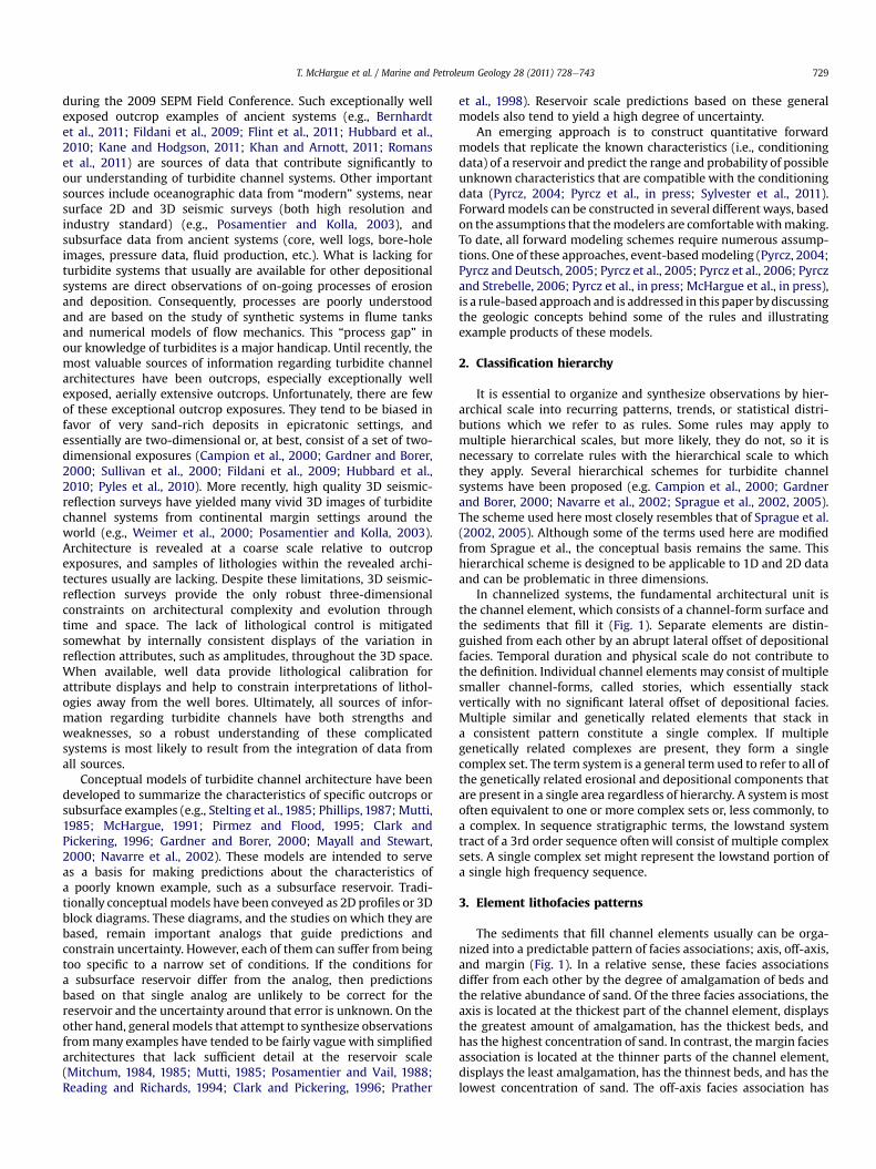
The sediments that fill channel elements usually can be orga-nized into a predictable pattern of facies associations; axis, off-axis,and margin (Fig. 1). In a relative sense, these facies associationsdiffer from each other by the degree of amalgamation of beds andthe relative abundance of sand. Of the three facies associations, theaxis is located at the thickest part of the channel element, displaysthe greatest amount of amalgamation, has the thickest beds, andhas the highest concentration of sand. In contrast, the margin faciesassociation is located at the thinner parts of the channel element,displays the least amalgamation, has the thinnest beds, and has thelowest concentration of sand. The off-axis facies association has

Fig. 1. Schematic representations of common fill styles of under-filled and filled channel elements. Although the contrasting characteristics as illustrated here are common for thesetwo channel types, variation is considerable. A: Under-filled channel element with moderate to high rate of overbank aggradation, semi-amalgamated highly heterolithic fill,common shale/silt drapes, and capped by upward fining abandonment-fill facies. B: Filled channel element with low rate of overbank aggradation, amalgamated and less het-erolithic fill, and rare shale/silt drapes. Upward fining abandonment-fill facies is thin or absent. If the channel element is over-filled, sandy overbank deposits may be present.Yellow¼ sand-rich channel-fill sediments, Green¼mud-rich channel-fill sediments, Brown¼mud-clast-rich channel-fill sediments, Gray¼mud-rich pre-existing sediments.
T. McHargue et al. / Marine and Petroleum Geology 28 (2011) 728e743730
characteristics that are intermediate between the other two faciesassociations. Because some channel elements are sandy highenergy features and others are much muddier, the channel-fillfacies associations are not defined by specific values of sandpercentage or bed thickness, but by the relative trend of thesevalues within a channel element.
Vertical trends of sand percentage or bed thickness withina single element also may be helpful for identifying which channel-fill facies association is present at a particular location (Fig. 1). Theaxis facies association, because of abundant amalgamation, tends tohave a blocky-shaped sandy grain-size profile with minormudstone interbeds. However, mudstone in the form of mass flowdeposits or thick shale-clast lag deposits often is present or evenabundant in the axis facies association and can cause considerablecomplications in the appearance of the vertical profile. In thechannel margin facies association, both sand abundance and bedthicknesses tend to increase upward and mudstone interbeds arecommon. Mass flow deposits and shale-clast lag deposits may bepresent in the margin facies association, but usually they are lesscommon in the margin than in the axis of the channel element. Theoff-axis facies association has intermediate characteristics betweenthe axis and the margin facies associations.
A fourth channel-fill facies association, the abandonment faciesassociation, is present in many, but not all, channel elements (Fig. 1).If present, it overlies all of the other channel-fill facies associations.In the channel abandonment facies association, both sand abun-dance and bed thickness tend to decrease upward and mudstoneinterbeds are common (Labourdette, 2007). Above the underlyingaxis facies association, the abandonment facies association tends tobe relatively sandy and amalgamated compared to the abandonmentdeposits that overlie the channel margin facies association (Fig. 1).
Cross-sections of single channel elements can be symmetrical orasymmetrical. In high resolution 3D seismic volumes and in high
resolution bathymetric images of modern channels on the oceanbottom, symmetrical channels have been noted at the straightsegments of channel elements, whereas asymmetrical elements arefound at sinuous channel bends with the thickest part of theelement displaced toward the outer bend (Abreu et al., 2003;Posamentier and Kolla, 2003; Deptuck et al., 2007). Likewise, theaxis facies association is located at the thick center of symmetricalchannels and is displaced from the center toward the thicker, outerportion of asymmetrical channel elements (Pyles et al., 2010).Accordingly, off-axis and margin facies associations may expand inwidth on the inner, thinner side of asymmetrical channel elementsand be narrow or absent at the outer, thicker side of the channelelement. The magnitude of asymmetry in channel elements isthought to be proportional to the magnitude of sinuosity (e.g.Gardner and Borer, 2000; Peakall et al., 2000; Abreu et al., 2003;Pyles et al., 2010), but robust documentation and quantificationof this relationship is lacking.
4. Channel dimensions
Although channel elements are not defined based on theirdimensions, some patterns have been detected that might proveinstructive for interpreting the depositional setting of isolatedoutcrops or well penetrations of channel elements. When buildingmodels in the absence of sufficient local information, the datacompiled in Fig. 2 can be used as a guide to size distributions ofchannel elements.
Element dimensions from any confined channelized system,whether levee-confined or erosionally confined, are included inFig. 2. Likewise, data are included in Fig. 2 regardless of sand/mudratio or paleo-seafloor gradient. Channel element dimensionsmeasured from outcrops and subsurface data have been compiledfrom the literature, supplemented with proprietary data collected

Fig. 2. Histograms of measured channel element widths and thicknesses. SD¼ standard deviation. N¼ number of measured examples. A: Histogram of channel element widthsfrom outcrop examples. B: Histogram of channel element widths from high quality 3D reflection seismic coherency data. C: Histogram of channel element thicknesses from outcropexamples. D: Histogram of channel element thicknesses from well logs (only penetrations through axis facies association).
T. McHargue et al. / Marine and Petroleum Geology 28 (2011) 728e743 731
by the authors. Only channel elements with the most completedimensions were included in Fig. 2.
4.1. Channel width
Good quality 3D seismic data provide an excellent opportunity tomeasure thewidths of many channel elements in multiple locations.These measurements demonstrate that the widths of channelelements typically fall between 100 and 300 m with an average of206m (Fig. 2). Measurements from outcrops suggest a wider rangeof values for channel element width with an average of 307 m(Fig. 2). The different results for the two data sets are not understood,but it is likely related to the following potential weaknesses of thedata sources. Because vertical resolution is poor in most conven-tional 3D seismic data sets relative to the thickness of channelelements, many elements fall within a single seismic wavelength.Therefore, seismic-based measurements of element width mayrepresent an average value between a maximum value at the top ofthe channel element and a minimum value at the base. Channelelement width measurements from outcrops are also potentiallybiased toward an overestimate of element widths because outcropsrarely are perpendicular to the flow direction of the channelelement. Therefore, element widths measured from outcropsgenerally are apparent widths that need to be corrected. Althoughthe correction is routinely attempted, the correction is alwayssubject to error. Other uncertainties result from mixing measure-ments frommultiple hierarchical levels. For example, the often citedcompilation of channel dimensions in Clark and Pickering (1996)contains no hierarchical information. For the compilation in Fig. 2,data from the literature were hierarchically classified by the authors.
4.2. Channel thickness
As discussed, even good quality 3D seismic data rarely providethe opportunity to collect robust measurements of channel element
thicknesses because of inadequate resolution. Fortunately, highquality outcrops can be well suited for providing accurate elementthicknesses (Clark and Pickering, 1996) and provide our best sourcefor channel thickness data (Fig. 2C). Nevertheless, channel thicknessmeasurements from outcrops can have significant errors. Forexample, sediments that fill the top of channel elements often aremuddy (Figueiredo et al., 2010; Flint et al., 2011) and may be poorlyexposed. This issue may lead to a significant underestimate ofchannel element thickness. Also, amalgamation of multiple sand-rich elements may make the base of some elements indistinct. Asmentioned above, other uncertainties result from imperfect expo-sure or incomplete published information as to what hierarchicallevel is being measured. Wells also can be a useful source of dataregarding channel element thicknesses. However, like outcrop datasets, amalgamation is a common source of uncertainty. Manychannel elements are thinned due to erosion by younger elements.Furthermore, many wells penetrate the channel element at a loca-tion that is less than its maximum thickness. Channel elementthicknesses from well data are included in Fig. 2D only if the wellpenetrated an uneroded element through the axial facies associa-tion. Outcrop examples yield amean of 13 mwhereas well data yielda mean of 10.7 m for channel element thickness (Fig. 2).
We hypothesize that the thickness of a channel element isrelated to depositional setting; either proximal vs. distal or, morelikely, high gradient vs. lowgradient. Documentation to support therelationship between channel element thickness and depositionalgradient is weak, because the interpretation of depositionalgradient is subjective for ancient examples.
5. Gradient patterns
5.1. Depth of erosion
Gradient influences turbidite channel architecture by contrib-uting to the force of turbidity flows; force is proportional to the

Fig. 3. Example bathymetric profiles (colored lines) from the continental slope of theNiger Delta showing thalweg elevations of six channel systems near the seafloor thatare well imaged by 3D reflection seismic surveys. In all but one of the examples,straight lines (black) closely approximate the thalweg profiles. These examplesdemonstrate that, although gradients differ for separate channel systems, mostchannel systems are well approximated by assuming a constant equilibrium gradientfor distances of several tens of kilometers down the slope. Therefore, it is reasonable toassume that channel gradient was nearly constant for a channel element for distancesgreater than expected for a single hydrocarbon accumulation. Examples wherea constant channel gradient is an inappropriate approximation (i.e. the shallowestexample illustrated here) can be anticipated because isochron thicknesses will varyalong the flow path in these instances.
T. McHargue et al. / Marine and Petroleum Geology 28 (2011) 728e743732
steepness of the gradient. The first order effect of gradient onarchitecture is its influence on the depth of erosion. For a givenchannel element, all else being equal, erosional depth is greatestwhere the gradient is steepest (Pirmez et al., 2000; Prather et al.,2000; Ferry et al., 2005). If channel element thickness iscontrolled solely by erosion, then element thickness would bea good approximation of slope gradient. This is most likely to betrue for sand-rich systems which generally lack appreciable over-bank development (Mutti, 1985; Mutti and Normark, 1987). But formuddy systems, overbank aggradation also contributes signifi-cantly to the thickness of channel elements and, on a local scale, thethickness of overbank aggradation may not correlate well withgradient (Pirmez and Imran, 2003).
5.2. Accommodation
An equilibriumprofile in turbidite channels, as influvial systems,is the theoretical elevation along the path of the channel at whichthere is no net erosion or deposition (Pirmez et al., 2000; Kneller,2003). The height of the equilibrium profile above the sedimentsurface at any point along the equilibrium profile represents thethickness of accommodation at that point in time (Posamentier andVail, 1988; Samuel et al., 2003). The gradient of the equilibriumprofile develops in response to changes in flow height, density, andgrain size. Larger, sandier flows trigger a decrease in the equilibriumgradient and, therefore, a decrease in accommodation whereassmaller, muddier flows trigger an increase in the equilibriumgradient and an increase in accommodation (Kneller, 2003). Overlong periods of time, accommodation at any point along a channelprofile changes substantially, but change tends to followa pattern inmost channel systems: erosion, to some degree, early in the historyof the channel system followed by deposition and aggradation latein the history of the system (Stelting et al., 1985; McHargue, 1991;Peakall et al., 2000; Deptuck et al., 2003; Kneller, 2003;Labourdette, 2007). Although the longitudinal profile of entirechannel systems often is concave (Pirmez et al., 2000; Pirmez andImran, 2003), the longitudinal profile of many turbidite channelsystems on the slope is nearly linear for several tens of kilometers(Fig. 3). Furthermore, despite substantial changes in accommoda-tion history, the gradient of the longitudinal profile of many turbi-dite channel systems appears to remain fairly constant throughtime. This pattern is illustrated by a near modern turbidite channelsystem offshore Nigeria, where the base of the erosional turbiditechannel system is nearly linear for 60 km, as interpreted fromexcellent quality 3D seismic data (Fig. 4). Likewise, at the time thesystemwas abandoned, the top of channel-fill and the tops of leveesalso constructed a smooth, linear, longitudinal bathymetric profile,approximately parallel to the original, erosional profile at the base ofthe system (Fig. 4). Apparently, the gradient of the equilibriumprofile changed littlewith time and a single accommodation historycan reasonably be applied to this entire channel segment. This is animportant simplifying assumption for constructing a forwardmodelof this type of turbidite channel system.
Although it has not been demonstrated,we assume formodelingpurposes that the apparently constant gradient of the equilibriumprofile for several tens of kilometers applies to element-scalearchitecture as well as to complex and complex set-scale architec-ture. So, for channel segments that are a few tens of kilometers long,it is assumed that a single accommodation cycle reasonably predictserosion and then fill of a channel element at all points along theentire length of the channel segment.Multiple elements result frommultiple accommodation cycles of similar scale.
On the other hand, if adjacent channel elements with verydifferent depths of erosion are present in the same system, thenequilibrium disruption (Pirmez et al., 2000) is indicated with
substantial changes in the gradient of the profile of one elementrelative to the other. Equilibrium disruption results either fromdramatic differences in the evolution of flow characteristics or fromtopographic irregularities along the flow path that are either toogreat or too dynamic to have been smoothed by erosion (e.g. theshallowest example in Fig. 3). Examples include ponded or fill-and-spill systems (Winker, 1996; Prather et al., 1998; Beaubouef andFriedman, 2000; Pirmez et al., 2000; Mayall and Stewart, 2001)and transient fans (Adeogba et al., 2005). Although systems likethese can be important hydrocarbon reservoirs, the simplifyingassumptions described in the previous paragraph are inappropriatefor modeling them.
6. Cyclicity patterns
6.1. Waxingewaning cycle
A cycle of channel erosion followed by deposition of channel-filling sediments has long been recognized (Mutti and Normark,1987, 1991). Building on this recognition, we find it useful tointerpret channelized turbidite deposits to be the product ofmultiple cycles of waxing flow energy followed by waning flowenergy at multiple scales. Each cycle is interpreted to result fromsystematic, and presumably gradual, changes in the volume andcaliber of turbidity flows through time triggering first a fall andthen a rise of the equilibrium profile (Kneller, 2003). In the waxingportion of an energy cycle, flows are relatively large and dense, andsediment caliber usually is coarse (sand-rich) relative to flows ofthe waning phase. Therefore, the waxing phase of the cycle driveserosion of a channel conduit as the equilibrium profile falls. Even-tually, successive flows gradually decrease in force; the equilibriumprofile stabilizes and then begins to rise. The rise of the equilibriumprofile marks the beginning of the waning phase of the energycycle. As the equilibrium profile rises in the waning phase, flowsprogressively become smaller, and usually muddier in caliber, with

Fig. 4. Example dip profile along a near-seafloor channel-levee system from the continental slope of the Niger Delta that is well imaged by 3D seismic data for over 60 km downslope. The original bathymetry prior to channel initiation, indicated by the dark blue horizon, is determined by identifying the depth of the youngest horizon truncated by thechannel system and downlapped by outer levees. The original surface is irregular, including a structurally elevated area near the distal end of the profile. The erosional base of thesystem is indicated by the red horizon. The top of active channel-fill (the top of high amplitude reflections in the system) is indicated by the yellow horizon; and the top of the righthand levee is indicated by the light blue horizon. Note that a nearly smooth profile is established immediately through erosion, despite significant irregularities on the initialseafloor profile. Elevated profiles after deposition within the channel system and on the levees are nearly parallel to the profile at the erosional base of the system.
T. McHargue et al. / Marine and Petroleum Geology 28 (2011) 728e743 733
decreasing density which allows deposition both within thechannel conduit and in overbank settings of increasingly muddysediments (Kneller, 2003; Labourdette, 2007; Wynn et al., 2007).Typically, an abrupt lateral shift of the channel position (avulsion)separates one cycle from the next (Sprague et al., 2002, 2005).Because most of the deposition takes place during the waningportion of the cycle compared to erosion during much of thewaxing phase, each cycle will likely appear highly asymmetrical inthe preserved stratigraphic record. The actual relative durationsand amplitudes of the two phases are unknown.
6.2. Allogenic drivers
The driving mechanisms of flow energy cyclicity are unknown.In this paper, allogenic cyclicity is treated as the primary drivingmechanism controlling waxingewaning cycles at all scales. In fact,allocyclicity may not control any of the cycles, but it is a convenientand simplifying assumption for modeling purposes that providestestable predictions. Several allogenic drivers, such as relative sealevel, tectonism, and climate, likely influence turbidite architecturebut the impact of one relative to another is unknown in most cases.Although autogenic processes presumably drive some of thechanges that are manifest in turbidite channel deposits, they arepoorly understood and difficult to use as a basis for making quan-tifiable predictions. If one wants to consider the effects of anyparticular autogenic process, it can be modeled within the cyclicalallogenic framework either stochastically, or as a set of rules. It isuseful to emphasize the cyclicity that is interpreted to result fromallogenic mechanisms because these cycles are systematic, areeasily modeled and will constrain predictions of the characteristicsof turbidite deposits and their stacking pattern. Assumed allogeniccyclicity provides the basis for developing statistically definabletrends that serve to constrain predictions, but presumably auto-genetic processes are responsible, at least in part, for the statisticalspread that impacts the uncertainty of the predictions.
6.3. Cycle hierarchy
In most turbidite successions, at least three scales of wax-ingewaning cyclicity can be interpreted: element, complex set, and
sequence. The element scale of cyclicity is responsible for the erosionand filling of a single channel element. Likewise, the complex setscale of cyclicity results in the accumulation of a complex set and thesequence scale of cyclicity results in the accumulation of a sequence.We consider these three scales one at a time.
A sequence-scale cycle is the most familiar scale of wax-ingewaning cyclicity and the best documented (Posamentier andVail, 1988; Posamentier et al., 1991; Mitchum et al., 1993). Asequence-scale cycle on the slope is expressedmost completely by (1)a sequence boundary followed by (2) one or more complex set-scalecycles of potentially sand-rich sediments followed by (3) thin beddedsiltstones of the lowstand wedge and then by (4) muddy deposits ofthe condensed section. Because the sequence scale of cyclicity hasbeen described many times in detail, it will not be discussed hereexcept to emphasize that the sequence inessence consists of awaxingphase, represented on the slopemostly by a stratigraphic surface, thesequence boundary, followed by increasingly muddy sedimentsdeposited during a trend of waning energy.
A complex set-scale cycle is expressed by a series of channelelements that may be confined entirely or in part by an erosionalvalley, by levees, or by a combination of both. The stacking pattern ofchannel elements deposited during a complex set-scale cycle resultsin a successionof channel complexes that tend to followapredictablepattern (Mutti, 1985; Mutti and Normark, 1987; McHargue, 1991;Mayall and Stewart, 2000; Peakall et al., 2000; Posamentier et al.,2000; Navarre et al., 2002; Sprague et al., 2002; Wynn et al., 2007).The erosional valley surface, if present, represents thewaxing part ofthe complex set cycle in a high gradient setting. The early elements ofthe waning portion of the cycle strongly amalgamate becauseaggradation between elements is small in magnitude and theamountof lateral offset betweenelements is limitedby thehigh reliefconfinement of erosional valley walls or levees. These amalgamatedchannel elements constitute an amalgamated channel complex. Asflow energy continues to wane, the equilibrium profile begins to riseso that the rate of aggradation between elements increases andamalgamation decreases with time. Aggradation from one channelelement to the next requires accumulation of overbank sediments(Mutti andNormark,1991; Clark and Pickering,1996; Kneller, 2003).Overbank sediments usually are mud-rich and an increasing rate ofaggradation implies that the mud fraction increases relative to sand

T. McHargue et al. / Marine and Petroleum Geology 28 (2011) 728e743734
as energy continues to wane (Kneller, 2003; Labourdette, 2007). Theaggrading succession of channel elements constitutes a separatechannel complex because the stacking patternof these aggradationalelements differs strongly from the highly amalgamated stackingpattern that underlies them. Typically, the rate of aggradationcontinues to increase (McHargue, 1991; Peakall et al., 2000;Posamentier et al., 2000) until the next complex set-scale cyclebegins, usually marked by abandonment of the active complex dueeither to avulsion or the end of turbidite sedimentation.
An element-scale waxingewaning cycle is expressed by the cutand fill of a single channel element. On the slope, a channel elementbegins with waxing flow energy that causes increased erosion ofthe substrate associated with a lateral shift of the channel position,that is, avulsion. Sediments within turbidity flows pass through thechannel conduit to be deposited far down slope, leaving very littlesediment behind within the channel except possibly for pebbly bedload lags at the channel base or muddy remnants of the dilute tailsof the flows (Gardner and Borer, 2000) that may line the channelmargin (Fig. 1). Although these deposits, called bypass deposits,often are very muddy, they represent some of the highest energyflows of the channel element (Mutti and Normark, 1987; Hubbardet al., 2010). Continued waxing energy causes continued erosionand extensive sediment bypass until flow energy begins to wane.Therefore, at a single outcrop or in a subsurface core, the waxingportion of the channel element energy cycle may be representedsolely by an erosional surface, possibly coated by bypass deposits. Itis not until flow energy begins to wane that a channel elementstarts to fill with sandy sediments (Gardner and Borer, 2000). Earlydeposits of the channel-fill often are highly amalgamated near theaxis of the channel and interbedded with draping, muddy, bypassdeposits at the channel margin (Fig. 1) (Campion et al., 2000). Atany single location, continued waning flow energy results indecreasing magnitude and extent of amalgamation upward withinthe channel as a smaller proportion of each flow bypasses thatlocation and more of the flow is deposited. Therefore, as flowenergy wanes, the rate of sediment aggradation increases and thefocus of deposition shifts progressively toward the proximal part ofthe channel profile, a process referred to as backfilling (Gardner andBorer, 2000). This means that at any one location, sandy beds willtend to thicken upward through the sediment fill of a channelelement as the focus of sedimentation approaches that locationalong the channel profile (Campion et al., 2000). However, becauseof extensive amalgamation at the channel axis the apparent,amalgamated bed thickness may be greater in the lower part of theaxial channel-fill. Therefore, the upward increase of bed thicknessoften is best expressed at the channel margins (Fig. 1) (Campionet al., 2000). The upward increasing trend in aggradation rate andbed thickness is accompanied by decreasing scour relief, decreasingamalgamation, and increasing preservation of interbedded muddydeposits as well as the tops of sandstone beds. The next elementcycle begins with abandonment of the old element due either toavulsion or the end of turbidite sedimentation.
6.4. Mass transport deposits
Mass transport deposits are an important component of manyslope channel systems at multiple scales (Mayall and Stewart,2000; Posamentier and Kolla, 2003; Mayall et al., 2006; Armitageet al., 2009). Although there is some evidence that slump anddebris flow deposits are most common near the base of a channelsystem (Mayall and Stewart, 2000; Posamentier and Kolla, 2003;Mayall et al., 2006), we have excluded mass transport depositsfrom the discussion above because their presence and abundance isnot reliably tied to cyclicity. We have chosen to consider masstransport deposits stochastically.
6.5. Avulsion
Avulsion is a critical process in the development of turbiditechannel architecture (Kolla, 2007). Unfortunately, this complicatedprocess is poorly understood. Here, we treat avulsion as being tiedto the initiation of the waxing phase of an energy cycle. During thewaning phase of the previous cycle, channel architecture, andespecially the relief of channel confinement, is in equilibrium withrelatively mud-rich, small and low energy flows. The initiation ofthe next energy cycle brings with it flows that are much sandier,more dense, and much more erosive. Therefore, the potential foravulsion is greater at this time than at any other time in the energycycle. Alternatively, some avulsions may be independent of anenergy cycle resulting from (1) exceptional, large, energetic,turbidity flows, (2) mass flow deposits, or (3) mass failure of a levee.The occurrence of these non-cyclical avulsions, in either time orspace, cannot be predicted as yet and are modeled stochastically.
7. Confinement hierarchy
The channel elements of some turbidite channel systems areconfined by a single set of levees. However, the morphology ofmany turbidite channel systems, especially when located on thecontinental slope, indicates that confinement of turbidity flows canoccur at two scales which wewill refer to as inner confinement andouter confinement (Fig. 5). Inner confinement, results from thecombination of erosion and/or overbank aggradation at the marginof a channel element, sometimes referred to as an inner levee or asan internal levee (Hubscher et al., 1997; Deptuck et al., 2003; Kaneand Hodgson, 2011). Outer confinement results from the combi-nation of erosion and/or overbank aggradation at the scale ofa complex set. Outer confinementmay take the form of an erosionalvalley wall, an outer levee, or a combination of the two. Increasedoverbank aggradation has an important impact on the stackingpattern of channel elements, potentially by increasing the amountof both inner confinement and outer confinement.
In the early part of the waning phase of a complex set-scaleenergy cycle the flows are large and probably sand-rich relative toflows later in the cycle (Kneller, 2003; Labourdette, 2007). Theaggradation rate of both the inner and outer confinements can below, limited by insufficient mud (Fig. 5). In this case, we speculatethat channel element relief is low and confined sediment tends tonearly fill each channel element. Because little relief remainsunfilled when the next element-scale cycle begins, the abandonedchannel element has little influence on the path taken by thesubsequent channel element. The result is a disorganized stackingpattern (McHargue et al., in press) (Fig. 6). We expect that disor-ganized stacking is favored by sand-rich flows that yield low rates ofoverbank aggradation and high rates of filling, especially when thecomplex set-scale cycle is in the early portion of the waning phase.
Mud-rich flows provide the mud volume that drives high rates ofaggradation of inner confinement. Importantly, if outer confinementis present, either as an outer levee or as an erosional valley wall, andhas sufficient relief, it is reasonable to expect that the overbanksediments of the channel elementwill be deflected and contained bythe outer confinement, thus further enhancing the rate of aggrada-tion on the inner confinement. Aggradation of the inner confinementincreases channel element relief and thereby increases the proba-bility that the channel element will not completely fill prior to initi-ation of the next element-scale energy cycle. The unfilled channelrelief (Fig. 5) has the potential to influence, or even capture, theenergeticflowsof thenextwaxingphase. If this occurs, the result is anorganized stacking pattern (McHargue et al., in press), where theposition and morphology of the subsequent channel element arestrongly influenced by the position and morphology of the previous

Fig. 5. A: Definition of channel element relief (R). Inner confinement is represented byan inner levee and outer confinement can be either an outer levee or an erosionalvalley wall. B: Definition of unfilled element relief (C).
T. McHargue et al. / Marine and Petroleum Geology 28 (2011) 728e743 735
element (Fig. 6). The second channel usually is offset by less thana channel width relative to the first channel (e.g. Posamentier et al.,2000; Posamentier and Kolla, 2003). We predict that mud-richflows favor the development of organized stacking, because mudcontributes most to the rate of overbank aggradation. Therefore, theprobability of developing organized stacking increases as thecomplex set-scalewaning phase progresses. The unfilled relief that ispresentwhena channel element is abandonedpresumably isfilledbyoverbank sediments from the next younger channel (Piper et al.,1999). We expect the sediments that fill the abandoned channelrelief to display anupwardfininggrain-size profile (Figs.1 and 7). Thedecompacted thickness of the upward fining interval representsaminimumestimateof theunfilled relief of a channel at the timeof itsabandonment.
8. Autogenic drivers and patterns of architectural changedown flow
8.1. Flow stripping, filtering, and scaling
Patterns of architectural change along a channel system arestrongly influenced by autogenic drivers, especially flow stripping.When the top of a turbidity flow becomes elevated above channelconfinement, then that unconfined portion of the flow spreads out,slows down and becomes detached from the underlying, confinedportion of the flow. This process is called flow stripping (Piper andNormark, 1983; Peakall et al., 2000; Posamentier et al., 2000). It isthe uppermost, mud-rich fraction of the flow that is preferentiallyremoved by flow stripping, because turbidity flows are stronglydensity stratified, concentrated at the base and dilute at the top.Therefore, flow stripping is an effective filter that preferentially
removes fine-grained sediment from channelized turbiditycurrents. Flow stripping usually results in deposition of the fine-grained component in overbank positions which contributes tolevee construction. Except for local variation, levee height tends togradually decrease down flow (Skene et al., 2002; Pirmez andImran, 2003; Posamentier and Kolla, 2003). Therefore, the chan-nelized portion of the flow progressively loses its top to flowstripping and mud to the overbank while its relative sandconcentration increases, a process we refer to as flow filtering.Flows can be thinner than the surrounding confinement, but theycannot remain thicker than confinement without the tops of theflows being stripped away. We refer to this effect as flow scaling;the height of the flow is scaled to the height of confinement.
Flow filtering tends to cause individual channelized flows tobecome thinner and sandier as they progress along their flow path.Flow scaling tends to constrain the upper limit of flow height ofrepeated channelized flows. Presumably, the effective longitudinalprofile of the channel is in equilibriumwith the time-averaged sizeand caliber of these scaled and filtered flows. Flow filtering isimportant for another reason as well. Flow filtering ensures that, aslong as the upper part of a flow is clay-rich, overbank sediments areclay-rich. Clay-rich sediments are cohesive and characterized bymoderate to high shear strength, making them relatively difficult toerode (Audet,1998). Cohesive banks are necessary for bank stabilityand confinement, and without bank strength, channels with highsinuosity are not stable with time (Audet, 1998). As flows progressdown slope, if gradient and levee height become progressivelylower, the muddy upper portion of the stratified flows eventuallywill be completely stripped away and the lower, sand-rich portionof the flows will begin to spill onto the overbank. Near this point,the channel banks will be too sandy to be cohesive and theconfinement height will be too low to be effective. We hypothesizethat channels with non-cohesive, sandy banks tend to have lowsinuosity and are unstable, avulsing frequently. The product isa weekly confined channel system, with laterally offset channelsand sandy overbank with a low aggradation rate. Channel elementsin this setting will be filled with sand-rich sediment and little if anyrecognizable abandonment deposits. Because of the low gradientand the low aggradation rate, each channel element will be thin.
9. Event-based approach to forward modeling
The observations, patterns, and hypotheses discussed thus far inthis paper, some well constrained and some conjectural, can beexpressed as mathematical statements which we refer to as rules.Rules are either empirical or predictive. Empirical rules are quan-titative summaries of statistically defined patterns, relationships, orobserved dimensions. Predictive rules generally are hypothesesregarding processes that are incompletely known. Rules are notindependent. Interaction and feedback can produce complicatedarchitectures from simple rules, as well as surprises which mayrequire the improvement of existing rules, the development of newrules, or lead to new insights.
Single rules are of limited value by themselves for makingquantitative predictions or quantitative characterizations of sparselysampled channel systems. It is only when these rules are appliedsystematically in a forward modeling technique that their predictivevalue is optimized. We use an event-based (EB) forward modelingtechnique that facilitates the integration of geological information byconstructing stochastic models as a sequence of depositional events(Pyrcz, 2004; Pyrcz et al., 2005; Pyrcz and Strebelle, 2006; Pyrcz et al.,2006; Pyrcz et al., in press). EB modeling is innovative in that it is (1)a forward model; (2) pseudo-process-based; (3) parameterized byflow axis centerlines and associated architectures; and (4) hierar-chical. The EB forward modeling laboratory has the capability of

Fig. 6. Schematic examples in plan view of channel complexes illustrating contrasting stacking patterns of four channel elements. The location of outer confinement on either sideof the channel complex is illustrated by a dashed line. A: Disorganized stacking pattern. The architecture and location of each element bears little resemblance to other elements. B:Organized stacking pattern with lateral offset of elements in a down-flow direction (arrow). The architecture and location of each element strongly resembles the previous element.
T. McHargue et al. / Marine and Petroleum Geology 28 (2011) 728e743736
quickly constructing many realizations of channel systems that areconsistent with the sparse constraints available from outcrop,seismic, or well control. From this suite of forward models, the rangeand probability of channel characteristics and their stacking patternscan be predicted quantitatively. After the experimental run, eachrealization of each model can be exhaustively analyzed to describethe genesis of each cell in the realization as well as property distri-butions and internal heterogeneities across each realization (Pyrczet al., 2005). The statistics from every realization of every accept-able model can be combined to address probability and uncertaintyof properties and their spatial distribution.
We acknowledge that rule-based approaches to processmodeling are less rigorous than physics-based approaches.However, physics-based processes are not adequately understood,the numerical methods are computationally intensive and resultingmodels often fail to reproduce high resolution architecture at
Fig. 7. Channel abandonment-fill overlying active channel-fill can be interpreted andthe thickness can be estimated from well logs. Abandonment-fill is indicated by anupward increase in gamma ray values due to an upward increase in clay content andan upward decrease in sand bed thickness. In this synthetic example, the upperchannel element, which is 21 m thick, consists of 9 m of active channel-fill overlain by12 m of abandonment-fill. Although preserved in this example, underlying elementsoften are partially eroded so that abandonment-fill is partially or entirely removed.
element scale. Rule-based models are able to: (1) use both empir-ical and predictive information summarized from partial analogs;(2) reproduce realistic architectures at element to complex setscales; and (3) generate a large number of model realizationsrapidly (one realization of a model with several million cells in tensof seconds on a regular PC).
9.1. Boundary conditions for EB slope channel models
In the present form of EB forward modeling for slope channelmodels, the starting surface can be planar, channel-form, or irreg-ular. The starting surface must be tilted basin-ward at a constantslope. The starting surface can be hypothetical or imported fromconstraining data such as a 3D seismic interpretation. Modeldimensions usually are several tens of kilometers long, a few kilo-meters wide, and a few hundred meters thick. Individual turbiditycurrents are not modeled. Instead, each event consists of the netproduct of a single architectural element, erosion plus fill, con-structed in response to the interaction of a set of rules. Elementerosion and aggradation are controlled by rules that interact withenergy cycles and substrate topography. The channel element isfilled deterministically with axis, off-axis, and margin facies asso-ciations in proportions that are either constant or sampled froma distribution. The characteristics of each facies association arederived from local data or from a database of regional examples.Asymmetry of channel-fill is proportional to local curvature of thechannel element. Subsequent channel elements may erodeprevious elements so that preserved channels and the preservedfacies proportions of channel-fills can be substantially differentfrom the original. For more detailed descriptions of the EBmodelingmethod, the reader is referred to Refs. Pyrcz (2004), Pyrczet al. (2005), Pyrcz and Strebelle (2006), Pyrcz et al. (2006), andPyrcz et al. (in press).
10. Slope channel predictive model
Thus far, we have described the patterns, trends, and opinionsthat constitute many of the rules upon which the following models

T. McHargue et al. / Marine and Petroleum Geology 28 (2011) 728e743 737
are based. These models are crude, but they are a beginning, nobetter or worse than the rules. As experience and new data allowimprovements in the rules, future models should improve as well.For example, initially, we were unable to generate an organizedstacking pattern of channel elements in our EB models. Conse-quently, wehypothesized that unfilled relief of one channel elementhad the potential to confine the subsequent channel element andcontribute to organized stacking (McHargue et al., in press). Afterincorporating this hypothesis as a rule, organized stacking formedin a logical manor, especially when rates of overbank aggradationwere high. Furthermore, without the need of additional rules, downslope translation (sweep) of younger elements developed incomplexes with organized stacking. This example of rule develop-ment emphasizes that an EBmodel is a hypothesis and illustrates anexample emergent behavior that matches observations of naturalsystems. The EB model benefits from being conditioned by specificdata sets in order to provide specific robust predictions forcomparison to real world examples. When coded in a forwardmodeling package such as EB, the predictions are quantitative, 3D,reproducible and therefore testable.
We hypothesize that on the continental slope, the evolution offlow caliber toward an increasing proportion of mud during thewaning phase of cycles at all scales tends to construct a channelcomplex set with a predictable succession of architectures. Aspectsof this architectural succession have been noted previously (e.g.Stelting et al., 1985: Mutti, 1985; Phillips, 1987; McHargue, 1991;Pirmez and Flood, 1995; Clark and Pickering, 1996; Gardner andBorer, 2000; Mayall and Stewart, 2000; Navarre et al., 2002;Posamentier and Kolla, 2003; Cross et al., 2009). In differentsettings along a profile, or in systems with different flow calibers,the prominence of any stage can vary or even be absent althoughthe stages are likely to occur in the following order: (1) erosion ofa complex set-scale container; (2) accumulation of sand-rich,laterally offset, amalgamated channel elements with low rates ofoverbank aggradation; (3) development of channel elements withdisorganized stacking and modest amalgamation as overbankaggradation begins to increase; and (4) establishment of under-filled channel elements with organized stacking as overbanksediments accumulate at a high rate (Fig. 8). As stated earlier, therelative prominence of each stage can vary considerably dependingon local conditions, position along the slope profile, and the caliberof supplied sediment. Also, exceptions to this model are to beexpected. The succession of stages can be interrupted by the initi-ation of a new complex set-scale cycle or truncated by erosion.These architectural stages and their implications in differentsettings and with different flow calibers are discussed here.
10.1. Mixed sand-mud system
The rules have been developed primarily to model turbiditechannel systems on the continental slope in which the time-aver-aged flow caliber is rich in both sand and mud (mixed sand-mudsystems) because these are important petroleum reservoirs. Someexamples of channel systems that display all four stages are: Angolasubsurface (Labourdette and Bez, 2010), the Joshua system of theGulf of Mexico (Posamentier, 2003), De Soto area system(Posamentier and Kolla, 2003), Niger western slope (Deptuck et al.,2007), and western Amazon (Nakajima et al., 2009). The specific EBmodels illustrated in Fig. 8 are of mixed sand-mud turbiditechannel systems on a moderately steep slope gradient (perhaps>1�). For comparison, the hypothesized architectures on a lowgradient will also be discussed. In addition, the hypothesizedvariations in architectures of sand-dominated and mud-dominatedsystems will be compared to the illustrated models. The illustratedEB models are for limited lengths, tens of kilometers, of channel
systems. This scale is sufficient to model the reservoirs of petro-leum accumulations while eliminating the need for many rules toaccount for down-flow changes in flow parameters due either tochanges in gradient or to evolving flow caliber (Fig. 3).
10.1.1. Stage 1, complex set-scale erosion (Fig. 8A)Erosion initiates the development of a slope channel system on
a moderate to high gradient. We assume that the slope channelsystem is eroded by many channel elements during the waxingphase of a complex set-scale cycle. These events are confined byinner confinement and the developing outer confinement as theequilibrium profile drops. During the waxing phase, the time-averaged flow caliber contains the highest proportion of sand andhas the greatest erosive power. In response to these energeticconditions, the equilibrium profile falls through time, drivingerosion. Except for clast-rich lags and fine-grained laminatedmudstone from the tail of turbidity currents, sediment transportedby these erosive flows bypasses the erosional valley to be depositedat some distal location where the gradient is low. A possibleexception is the potential to preserve channel remnants oferosional terraces on the flank of the valley (Fig. 9).
10.1.2. Stage 2, amalgamation (Fig. 8B)As the waxing phase gradually transitions to the early waning
phase of the complex set-scale cycle, the equilibrium profilestabilizes and the slope channel system no longer deepens.Deposits of the coarsest components of the flows are preserved asbed load lags on the valley floor. The entire valley is draped withmud-rich deposits that represent the tails of bypassing flows, butthese deposits might be preserved only on the flanks of the valleybecause subsequent flows are still energetic enough to re-erodethem near the axis. In this early stage of sedimentation, the accu-mulation of mass transport deposits is common and occasionallyvoluminous. Although important components of the fill, masstransport deposits have not been included in the illustrated model(Fig. 8). As the waning phase progresses, the time-averaged flowcaliber becomes slightly muddier and the equilibrium profilebegins to slowly rise. Sediment bypass becomes less effective andincreasingly, sand-rich deposits accumulate within the erosionalconfinement of each channel element. Some fine-grained sedi-ments accumulate as overbank deposits within the valley but theyare not often preserved, because, due to low rates of aggradation,subsequent avulsion and re-incision by younger elements reworkthese deposits and carry them farther down system. The resultingarchitecture is highly amalgamated, containing laterally offsetchannel elements. Overbank aggradation is very low and channelelements are filled with sand-rich sediments so inner confinementis ineffective and prominent avulsions result in disorganizedstacking.
10.1.3. Stage 3, disorganized stacking (Fig. 8C)As the waning energy phase progresses, the time-averaged
caliber of repeated flows becomes increasingly muddy, the equi-librium profile rises and both the channel elements and theiroverbank deposits aggrade at an increasing rate. Increased aggra-dation requires deposition of increasing volumes of mud-richsediments in overbank positions (inner confinements in Fig. 8)within the valley because successive channel elements cannotaggrade without aggradation of the overbank. Likewise, as theoverbank aggradation component of confinement increases rela-tive to the erosional component, channel amalgamation decreasesand the volume of channel deposits decreases relative to thevolume of overbank sediments. The potential for development andgrowth of outer improves at this time, but may be prevented ifvalley relief is too great to allow turbidites to overflow the valley

Fig. 8. Example event-based forward model showing 4 architectural stages. Each display shows the surface of a representative event (channel element plus overbank deposits) aspreserved after erosion by younger events. The total accumulated sediments at the locations of three cross-sections are illustrated for reference. Depth of erosion of valley floor orwalls¼ red (shallowest), yellow, green, and blue (deepest). Within valley-fill deposits as seen in plan view, yellow¼ overbank deposits of the selected event. The channel elementsthat erode the selected event are shown as blue (deep erosion) or green (shallow erosion). In the three cross-sections, all accumulated sediments at each of the three locations areillustrated. In the cross-sections, the facies associations of channel-fill are represented by orange (axis), yellow (off-axis), green (margin), and gray (abandonment). Overbankdeposits are represented as gray. The model is 2 km� 10 km� 200 m. Vertical exaggeration¼ 5�. A: Stage 1 erosion. This figure shows the valley at maximum erosion withoutsediment fill. B: Stage 2 channel amalgamation with low rate of aggradation. C: Stage 3 Disorganized channel stacking pattern with moderate rate of aggradation. D: Stage 4Organized channel stacking pattern with high rate of aggradation.
T. McHargue et al. / Marine and Petroleum Geology 28 (2011) 728e743738
walls. If all of the overbank muds are confined by the valley walls,then the aggradation rate of inner confinement can be high andchannel elements will not fill with sediments before the nextelement-scale energy cycle begins. Nevertheless, the under-filledrelief of channel elements is insufficient to confine the flows of thenext element-scale waxing phase which is marked by avulsion.As a result, channel elements stack in a disorganized pattern.
10.1.4. Stage 4, organized stacking (Fig. 8D)As the waning energy phase continues to progress, the time-
averaged caliber of repeated flows becomes even muddier, theequilibrium profile continues to rise and channel elements aggradeat an increasing rate along with their overbank deposits.The unfilled relief of under-filled channel elements increasesbecause of the increasing contribution of overbank (innerconfinement) aggradation to channel relief. The unfilled relief isnow sufficient to confine the energetic waxing flows of the next
element-scale energy cycle. Organized stacking of channelelements results where each younger channel element is forced tofollow near the path of the previous channel element (Figs. 6 and9). Flow momentum focuses erosion of channel walls in a down-slope direction resulting in offset of successive elements (Fig. 10A).The increasing rate of overbank aggradation is associated withdecreasing erosion during each element-scale waxing phase.Nevertheless, channel amalgamation increases, because the changefrom disorganized to organized stacking superimposes channelelements. In very muddy systems, extremely organized superim-poses successive channel elements (Pirmez et al., 2000;Posamentier et al., 2000; Popescu et al., 2001; Posamentier, 2003;Posamentier and Kolla, 2003; Schwenk et al., 2005; Deptucket al., 2007). Perhaps very muddy systems with turbidity currentsof long duration are one situation that favors the development oflateral accretion with expanding meander loop radii, and highsinuosities similar to fluvial systems.

Fig. 9. Multiple cross-sections through EB model in Fig. 8. Each cross-section shows the channel elements and overbank deposits and their stacking pattern within the erosionalvalley container. The relative ages of channel elements are shown by color: blue (oldest) to green, yellow, orange, and red (youngest). Overbank deposits are transparent. Because ofchannel sinuosity, organized stacking is expressed locally in a variety of ways: vertical stacking, sections 1 and 7; persistent lateral offset, sections 3 (right) and 4 (left); a reversal ofoffset direction, section 6; and local, brief disruption of organized stacking, sections 2 and 5. Possible channel remnants on erosional terraces can be seen along the valley walls onsections 2 and 5 or at the top of the valley in sections 3e6. Vertical exaggeration¼ 5�.
T. McHargue et al. / Marine and Petroleum Geology 28 (2011) 728e743 739
Eventually, a new complex set-scale energy cycle begins with farmore energetic sandy flows during the waxing phase. Complex set-scale avulsion is most likely at this time but if outer confinement issufficiently high, either as unfilled erosional valley confinement oras high relief outer levees, the next complex set may be captured bythe unfilled relief of the older complex set. This is most likely inproximal settings with deeply eroded slope channel systems onsteep slopes.
10.2. Architectures on a low gradient
The same flows that produce the modeled architecture dis-cussed above will produce very different architectures in distalareas of low gradient (perhaps 0.5� or less for mixed sand-rich andmud-rich systems). We hypothesize that stage 1 erosion will beminor or even absent. In stage 2, any erosional relief that is presentwill be occupied by amalgamated channel elements filled by sand-rich sediments (Fig. 1B). In stage 3 at this setting, the caliber ofoverbank sediment is critical in determining architecture. Forexample, the Makassar Strait system contains enough mud to buildprominent levees at the base of slope (Posamentier et al., 2000;Posamentier and Kolla, 2003). The levees provide sufficientconfinement with rapid aggradation to allow a channel stackingpattern that evolves through stages 1e4. However, rapid depletionof mud down flow, as a consequence of flow stripping, causesmixed sand-mud flows to evolve rapidly into sand-rich flows. In thedistal Makassar system, as in other sand-rich systems in a lowgradient setting, the mud that remains in the upper portion of theflows is deposited on the overbank. However, the levees are toosmall to confine multiple element cycles so avulsion betweenelements is likely and organized stacking of stage 4 cannot develop.If mud volume is insufficient to allow the development of effectivecohesive banks, confinement is weak, the rate of overbank aggra-dation is very low, channel elements are thin, and stage 3 aggra-dation is slight to absent. Sand-rich sediments overfill most
channel elements, further contributing to a sand-rich overbank.The resulting architecture will be a weakly confined (stage 2)channel system in which frequent avulsion and channel instabilityare common. Examples include portions of the Ross formation(Sullivan et al., 2000; Elliott, 2000), the Ongeluks River section ofthe Tanqua Karoo (Sullivan et al., 2000), the distal portion of theMakassar Strait system (Posamentier et al., 2000; Posamentier andKolla, 2003), and near surface features of the Niger slope (Adeogbaet al., 2005).
10.3. Mud-dominated systems
We hypothesize that on a high gradient beyond the canyonmouth, systems with a time-averaged flow caliber that is mud-dominated may exhibit only small to moderate erosion duringstage 1, if any (e.g., aggradational zone of the Indus Fan (McHargueandWebb, 1986)). In stage 2, inner confinements may be small andouter levees ineffective if flows are sufficiently sandy, allowingamalgamation of channel elements across a broad area. However,because of the great volumes of mud in the flows, moderate to highrates of muddy overbank aggradation quickly result in the devel-opment of effective inner and outer levee confinement with highrates of aggradation. The disorganized stacking of stage 3 may bevery short lived or even absent, giving way rapidly to stage 4organized stacking and highly under-filled channel elements.Because of the high rate of inner confinement aggradation, a specialcase of organized stacking, lateral accretion, may develop alongwith prominent swing of meander loops and very high sinuosities.
In a more distal setting, on a low slope gradient, we hypothesizethat stage 1 erosion will be unlikely. Because the time-averagedflow caliber contains somuchmud, both stages 2 and 3 can be shortlived or even absent and channel elements may aggrade rapidlyalong with muddy levees. Stage 4 organized stacking of highsinuosity channel elements, possibly including lateral accretion,dominates the system almost from the start. Examples of mud-rich

Fig. 10. Example quantitative products of the EB model in Fig. 8. A: 3D distribution of facies associations within channel elements. Axis¼ orange, off-axis¼ yellow, margin¼ green,abandonment and overbank deposits are transparent. Facies associations within any channel element can be asymmetrical in distribution at channel bends. The erosional surface ofthe valley walls is brown. B: Map of total sediment isopach superimposed on the valley model. Sediment thickness shown in red (thickest), yellow, green, blue, purple (thinnest).C: 3D volume of reservoir porosity based on statistical distributions for each facies association. Overbank deposits are transparent. Porosity within channel elements is indicated byred (highest porosity), yellow, light blue, dark blue (lowest porosity). The erosional surface of the valley walls is brown. D: Map of total reservoir pore volume superimposed onvalley model. The total pore volume map represents the vertical summation of the thickness of each porosity value shown in C. Total pore volume for the model is indicated by red(highest pore volume), yellow, green, blue (lowest pore volume). Vertical exaggeration¼ 5�.
T. McHargue et al. / Marine and Petroleum Geology 28 (2011) 728e743740
systems that display moderately to poorly developed architecturesof stages 2 and 3 followed by prominent stage 4 organized stackinginclude the Amazon Fan (Pirmez et al., 2000), the Danube Fan(Popescu et al., 2001), and the Indus Fan (Schwenk et al., 2005). Thisarchitecture will persist distally until flow filtering removesmost ofthe mud from the upper part of the flow so that overbank sedi-ments are sufficiently sandy that outer levees are no longer cohe-sive. At this point, overbank deposits no longer effectively confineflows and channel positions and morphology are unstable. Aweakly confined (stage 2) channel system develops consisting ofrapidly avulsing, laterally offset channel elements. This zone ofunstable, weakly confined channels will give way to a distributarysystem down flow and development of tabular sand bodies. Thisweakly confined to unconfined architecture may persist until thesystem is abandoned but if sufficient mud is introduced with timeduring the waning phase of the energy cycle, a channel-leveesystem may develop on top of the weakly confined to unconfinedsystem containing architectures of stages 3 and 4.
10.4. Sand-dominated systems
We hypothesize that on a high gradient, systems with a time-averaged flow caliber that is sand-dominated may erode a highrelief valley during stage 1 providing high relief outer confinement.During stage 2 amalgamation, channel elements aggrade slowlybecause sparse volumes of mud in the flows limit the rate ofoverbank aggradation. Element-scale erosion provides the onlyeffective inner confinement for the sandy flows because sandychannel banks are non-cohesive and unstable. As a consequence,stage 2 channel amalgamation, perhaps including braided channelarchitectures, may dominate the entire system. Alternatively, if
sufficient clay is available in the late flows of thewaning cycle, bankcohesion may develop, permitting the construction of disorganizedstacking of filled channels (stage 3).
In a more distal low gradient setting, we hypothesize that insystems with a time-averaged flow caliber that is sand-dominated,stage 1 erosion may provide the only available outer confinement.As long as erosional outer confinement relief is effective, stage 2,laterally offset, amalgamated channel elements with low rates ofaggradation and disorganized stacking fill the erosional outerconfinement. Insufficient mud is available to allow formation ofouter levees with appreciable relief so outer levees either are toosmall to effectively confine channel elements or levee confinementis short lived. Once the outer confinement is filled, avulsion allowschannel elements to spread beyond the original boundaries of theerosional valley and aweakly confined channel systemwith rapidlyavulsing, laterally offset channel elements develops. Further downflow, unconfined tabular sand bodies are deposited. An example ofa sand-rich system with architectures of stages 1 and 2 in a prox-imal setting and stage 2 in a distal setting is located on the easternmargin of Corsica (Deptuck et al., 2008).
11. Discussion
We hypothesize that channel stacking patterns withina complex set-scale cycle tend to progress through a succession ofarchitectural stages. These architectural stages are consistent witha suite of rules (observations, measurements, and hypotheses) forerosional slope channel systems on steep to moderate gradientswith mixed sand-mud calibers. So, the architectural stages prob-ably are best suited for constructing models of slope channelsystems. Whereas some complex sets will display all of the four

T. McHargue et al. / Marine and Petroleum Geology 28 (2011) 728e743 741
stages, many complex sets will not. For example, some complex setsmay be abandoned prior to development of stage 4 and the youngerstages of some complex sets may be removed by the erosion froma younger complex set-scale cycle. Or, multiple complex sets withdiffering sediment calibers, different slope settings, or differentaggradation rates may follow the same succession of stages butwith changing proportions. We expect that stages 1e2 will domi-nate sand-rich complex sets whereas mud-rich levee-confinedchannel complex sets will be dominated by stages 2e4, or even3e4. Lateral accretion is not included as part of the four architec-tural stages but we suspect that one favored setting for lateralaccretion is late in the waning phase of a mud-rich complex setduring stage 4 e organized stacking with high rates of aggradationof under-filled channel elements. Admittedly, there are channelcomplex sets with characteristics that appear to be inconsistentwith the rules described here but we feel that these architecturalstages serve as a useful standard for comparison.
The architectural stages and the rules from which they arederived are of limited value by themselves for making quantitativepredictions or quantitative characterizations of sparsely sampledchannel systems. The quantitative predictive power of rules is bestexploited when rules are applied systematically in a forward event-based modeling package (McHargue et al., in press; Pyrcz et al., inpress) to construct artificial 3D channel systems with realisticarchitectures (Figs. 8e10). Constructed models are dependent onthe rules but are objective, reproducible and quantifiable and can beconditioned to available data. Interaction and feedback of simplerules canproduce complicated architectures, such as the four stages,as well as surprises that may require the improvement of existingrules or the development of new rules. Multiple realizations andmultiple alternative models can be constructed to quantitativelyexamine the probability of specific parameters of interest such asnet volume, net-to-gross, connectivity, and tortuosity.
Examples of quantification are illustrated in Fig. 10. Examplesinclude the 3D distribution of facies associations (Fig.10A), a map oftotal sediment thickness within the slope channel system (Fig. 10B),the 3D distribution and quality of reservoir porosity (Fig. 10C), anda map of total reservoir pore volume (Fig. 10D). Furthermore, byrunning many models constructed with input values that span theentire reasonable range for each variable, a suite of possible modelsthat are compatible with existing constraining data can beproduced and statistically analyzed (Pyrcz et al., in press). The samemodels can be used to define probabilities for other specific attri-butes, such as pore volume, connectivity, and tortuosity.
12. Conclusions
1. Rules: The study of many slope channel systems has led to thedevelopment of rules in the form of observations, measure-ments, and hypotheses. The rules were developed with theobjective of constructing forward models of petroleum reser-voirs in erosional slope channel systems on steep to moderategradients with mixed sand-mud calibers. However, we antici-pate that the rules are applicable to a broader range of slopechannel systems.
2. Architectural hierarchy: The consistent application of an archi-tectural hierarchy is critical to organizing observations andmeasurements from diverse channel systems. In channelizedsystems, the fundamental architectural unit is the channelelement, which consists of a channel-form surface and thesediments that fill it. Separate elements are distinguished fromeach other by an abrupt lateral offset of depositional facies.Multiple similar elements that stack in a consistent pattern canbe grouped into a single complex, and, if multiple geneticallyrelated complexes are present, they can be grouped into
a single complex set. The term system is a general term used torefer to all of the genetically related channel components thatare present in a single area regardless of hierarchy.
3. Facies associations: Within a channel element, four faciesassociations are recognized: axis, off-axis, margin, and aban-donment. In a relative sense, axis, off-axis, and margin differfrom each other by the degree of amalgamation of beds and therelative abundance of sand, both of which are most common inthe axis. The abandonment facies association overlies the otherthree facies associations in some channel elements and ischaracterized by an upward increase in mudstone interbeds.
4. Channel organization: The thickness of the abandonment faciesassociation is a basis for estimating the thickness of unfilledchannel element relief at the time of channel abandonment.We hypothesize that low abandonment relief will have littleinfluence on the location of the subsequent channel elementand will result in a disorganized channel stacking pattern.Conversely, high abandonment relief can strongly influence thelocation of the subsequent channel element and will result inan organized channel stacking pattern in which the path of theyounger channel element approximates the path of the formerelement.
5. Waxingewaning cyclicity: We find it useful to interpret chan-nelized turbidite deposits to be the product of multiple cyclesof waxing flow energy followed by waning flow energy atmultiple scales. Each cycle is interpreted to result fromsystematic changes in the volume and caliber of turbidity flowsthrough time triggering first a fall of the equilibrium profile,which drives erosion and sediment bypass of the slope, fol-lowed by a rise of the equilibrium profile, which allows depo-sition on the slope of increasingly mud-rich sediments throughtime.
6. Cycle hierarchy: In most turbidite successions, at least threescales of waxingewaning cyclicity can be interpreted: element,complex set, and sequence. The element scale of cyclicity isresponsible for the erosion and aggradation of a single channelelement. Likewise, the complex set scale of cyclicity results inthe accumulation of a complex set, and the sequence scale ofcyclicity results in the accumulation of a sequence.
7. Architectural stages: The stacking pattern of channel elementswithin a complex set-scale cycle tends to be sequential: (1)erosion and sediment bypass; (2) amalgamation of channelelements associated with a low rate of aggradation; (3)a disorganized stacking pattern of channel elements associatedwith a moderate rate of aggradation; and (4) an organizedstacking pattern of channel elements associated with a highrate of aggradation.
8. Variability of architectural stages: Depending on variations inslope gradient, aggradation rate, and sediment caliber, therelative expression of the four stages will vary. For example,stages 1 and 2 may be absent or minor in mud-rich complexsets but prominent in sand-rich complex sets. Conversely, stage4 may be prominent in mud-rich complex sets but absent insand-rich complex sets. We hypothesize that organized stack-ing in particularly mud-rich complex sets may be one situationthat favors the development of channel lateral accretion. Werecognize that there are channel systems with characteristicsthat appear to be inconsistent with the sequence of architec-tural stages proposed here. Nevertheless, we expect that thismodel serves as a useful standard for comparison of diversechannel systems.
9. Event-based forward modeling: Interaction and feedback ofsimple rules within the event-based forward modeling labo-ratory produces realistic architectures, such as the four stagesdescribed above. Multiple realizations and multiple alternative

T. McHargue et al. / Marine and Petroleum Geology 28 (2011) 728e743742
models can be constructed to quantitatively examine theprobability of specific parameters of interest.
Acknowledgements
The authors are grateful to Chevron Energy TechnologyCompany for supporting the research and for providing permissionto publish. Helpful reviews with suggestions for substantiveimprovements were provided by Drs. David Hodgson, Bill Morris,and Steve Hubbard, who are greatly appreciated.
References
Abreu, V., Sullivan, M., Pirmez, C., Mohrig, D., 2003. Lateral accretion packages(LAPs): an important reservoir element in deep water sinuous channels. Marineand Petroleum Geology 20, 631e648.
Adeogba, A.A., McHargue, T.R., Graham, S.A., 2005. Transient fan architecture anddepositional controls from near-surface 3-D seismic data, Niger Delta conti-nental slope. American Association of Petroleum Geologists Bulletin 89,627e643.
Armitage, D.A., Romans, B.W., Covault, J.A., Graham, S.A., 2009. The influence ofmass-transport-deposit surface topography on the evolution of turbiditearchitecture: The Sierra Contreras, Tres Pasos Formation (Cretaceous), southernChile. Journal of Sedimentary Research 79, 287e301.
Audet, D.M., 1998. Mechanical properties of terrigenous muds from levee systemson the Amazon Fan. In: Stoker, M.S., Evans, D., Cramps, A. (Eds.), GeologicalProcesses on Continental Margins: Sedimentation, Mass-Wasting and Stability,vol. 129. Geological Society of London, Special Publication, pp. 133e144.
Beaubouef, R.T., Friedman, S.J., 2000. High-resolution seismic/sequence strati-graphic framework for the evolution of Pleistocene intra slope basins, WesternGulf of Mexico: depositional models and reservoir analogs. In: Weimer, P., Slatt,R.M., Coleman, J., Rosen, N.C., Nelson, H., Bouma, A.H., Styzen, M.J., Lawrence,D.T. (Eds.), Deep-Water Reservoirs of The World. Gulf Coast Section SEPM 20thBob F. Perkins Research Conference, pp. 40e60.
Bernhardt, A., Jobe, Z.R., Lowe, D.R., 2011. Stratigraphic evolution of a submarinechannelelobe complex system in a narrow. Marine and Petroleum Geology 28,785e806.
Campion, K.M., Sprague, A.R., Mohrig, D., Lovell, R.W., Drzewiecki, P.A., Sullivan,M.D., Ardill, J.A., Jensen, G.N., Sickafoose, D.K., 2000. Outcrop expression ofconfined channel complexes. In: Weimer, P., Slatt, R.M., Coleman, J., Rosen, N.C.,Nelson, H., Bouma, A.H., Styzen, M.J., Lawrence, D.T. (Eds.), Deep-Water Reser-voirs of The World. Gulf Coast Section SEPM 20th Bob F. Perkins ResearchConference, pp. 127e150.
Clark, J.D., Pickering, K.T., 1996. Submarine Channels: Processes and Architecture.Vallis Press, London, pp. 231.
Cross, N.E., Cunningham, A., Cook, R.J., Taha, A., Esmaie, E., El Swidan, N., 2009.Three-dimensional seismic geomorphology of a deep-water slope-channelsystem: the Sequoia field, offshore west Nile Delta, Egypt. American Associationof Petroleum Geologists Bulletin 93, 1063e1086.
Deptuck, M.E., Steffens, G.S., Barton, M., Pirmez, C., 2003. Architecture and evolutionof upper fan channel-belts on the Niger Delta slope and in the Arabian Sea.Marine and Petroleum Geology 20, 649e676.
Deptuck, M.E., Sylvester, Z., Pirmez, C., O’Byrne, C., 2007. Migrationeaggradationhistory and 3-D seismic geomorphology of submarine channels in the Pleisto-cene Benin-major Canyon, western Niger Delta slope. Marine and PetroleumGeology 23, 406e433.
Deptuck, M.E., Piper, D.J.W., Savoye, B., Gervais, A., 2008. Dimensions and archi-tecture of late Pleistocene submarine lobes off the northern margin of EasternCorsica. Sedimentology 55, 869e898.
Elliott, T., 2000. Depositional architecture of a sand-rich, channelized turbiditesystem: the Upper Carboniferous Ross Sandstone Formation, westernIreland. In: Weimer, P., Slatt, R.M., Coleman, J., Rosen, N.C., Nelson, H.,Bouma, A.H., Styzen, M.J., Lawrence, D.T. (Eds.), Deep-Water Reservoirs ofThe World. Gulf Coast Section SEPM 20th Bob F. Perkins Research Confer-ence, pp. 342e373.
Ferry, J.-N., Mulder, T., Parize, O., Raillard, S., 2005. Concept of equilibrium profile indeep-water turbidite systems: effects of local physiographic changes on thenature of sedimentary process and the geometries of deposits. In: Hodgson, D.M.,Flint, S.S. (Eds.), Submarine Slope Systems: Processes and Products. SpecialPublication, vol. 244. Geological Society, London, pp. 181e193.
Figueiredo, J.J.P., Hodgson, D.M., Flint, S.S., Kavanagh, J.P., 2010. Depositional envi-ronments and sequence stratigraphy of an exhumed Permian mudstone-dominated submarine slope succession, Karoo Basin, South Africa. Journal ofSedimentary Research 80, 97e118.
Fildani, A., Hubbard, S.M., Romans, B.W., 2009. Stratigraphic evolution of deep-water architecture: Examples of controls and depositional styles from theMagallanes Basin. SEPM Field Trip Guidebook, southern Chile, 10, 73 pp.
Flint, S.S., Hodgson, D.M., Sprague, A.R., Brunt, R.L., Van der Merwe, W.C.,Figueiredo, J., Prélat, A., Box, D., Di Celma, C., Kavanagh, J.P., 2011. Depositionalarchitecture and sequence stratigraphy of the Karoo basin floor to shelf edge
succession, Laingsburg depocentre, South Africa. Marine and PetroleumGeology 28, 658e674.
Gardner, M.H., Borer, J.M., 2000. Submarine channel architecture along a slope tobasin profile, Brushy Canyon Formation, West Texas. In: Bouma, A.H., Stone, C.G.(Eds.), Fine-Grained Turbidite Systems. Memoir 72-American Association ofPetroleum Geologists and Special Publication 68-SEPM, pp. 195e214.
Hubbard, S.M., Fildani, A., Romans, B.W., Covault, J.A., McHargue, T.R., 2010. High-relief clinoform development: insights from outcrop, Magallanes Basin, Chile.Journal of Sedimentary Research 80, 357e375.
Hubscher, C., Spiesz, V., Breitzke, M., Weber, M.E., 1997. The youngest channel leveesystem of the Bengal Fan: results from digital sediment echosounder data.Marine Geology 21, 125e145.
Kane, I.A., Hodgson, D.M., 2011. Sedimentological criteria to differentiate submarinechannel levee subenvironments: exhumed examples from the Rosario Fm.(Upper Cretaceous) of Baja California, Mexico, and the Fort Brown Fm.(Permian), Karoo Basin, S. Africa. Marine and Petroleum Geology 28, 807e823.
Khan, Z.A., Arnott, R.W.C., 2011. Stratal attributes and evolution of asymmetricinner- and outer-bend levee deposits associated with an ancient deep-waterchannel-levee complex within the Isaac Formation, southern Canada. Marineand Petroleum Geology 28, 824e842.
Kneller, B., 2003. The influence of flow parameters on turbidite slope channelarchitecture. Marine and Petroleum Geology 20, 901e910.
Kolla, V., 2007. A review of sinous channel avulsion patterns in some major deep-sea fans and factors controlling them. Marine and Petroleum Geology 24,450e469.
Labourdette, R., 2007. Integrated three-dimensional modeling approach of stackedturbidite channels. American Association of Petroleum Geologists Bulletin 91,1603e1618.
Labourdette, R., Bez, M., 2010. Element migration in turbidite systems: random orsystematic depositional processes? American Association of Petroleum Geolo-gists Bulletin 94, 345e368.
Mayall, M., Stewart, I., 2000. The architecture of turbidite slope channels. In:Weimer, P., Slatt, R.M., Coleman, J., Rosen, N.C., Nelson, H., Bouma, A.H., Styzen,M.J., Lawrence, D.T. (Eds.), Deep-Water Reservoirs of The World. Gulf CoastSection SEPM 20th Bob F. Perkins Research Conference, pp. 578e586.
Mayall, M., Stewart, I., 2001. The architecture of turbidite slope channels. In: Fraser,S.I., Fraser, A.J., Johnson, H.D., Evans, A.M. (Eds.), Petroleum Geology of Deep-water Depositional Systems, Advances in Understanding 3D Architecture. TheGeological Society Conference, March 20e22, 2001 Proceedings, BurlingtonHouse, Picadilly, London. The Geological Society, unpaginated.
Mayall, M., Jones, E., Casey, M., 2006. Turbidite reservoirsdkey elements in faciesprediction and effective development. Marine and Petroleum Geology 23,821e841.
McHargue, T.R., 1991. Seismic facies, processes, and evolution of Miocene inner fanchannels, Indus Submarine Fan. In: Weimer, P., Link, M.H. (Eds.), Seismic Faciesand Sedimentary Processes of Submarine Fans and Turbidite Systems. SpringerVerlag, New York, pp. 403e413.
McHargue, M.J., Pyrcz, M.D., Sullivan, J.D., Clark, A., Fildani, B.W., Romans, J.A.,Covault, M., Levy, H.W., Posamentier, Drinkwater, N.J., in press. Event-basedmodeling of turbidite channel fill, channel stacking pattern, and net sandvolume. SEPM Special Publication.
McHargue, T.R., Webb, J.E., 1986. Internal geometry, seismic facies, and petroleumpotential of canyons and inner fan channels of the Indus Submarine Fan.American Association of Petroleum Geologists Bulletin 70, 161e180.
Mitchum, R.M. Jr., 1984. Seismic stratigraphic recognition criteria for submarinefans. Gulf Coast Section SEPM Foundation Fifth Annual Research Conference, pp.63e85.
Mitchum Jr., R.M., 1985. Seismic stratigraphic recognition of submarine fans. In:Berg, O.R., Woolverton, D.G. (Eds.), Seismic Stratigraphy II, vol. 39. AmericanAssociation of Petroleum Geologists, pp. 117e136.
Mitchum Jr., R.M., Sangree, J.B., Vail, P.R., Wornardt, W.W., 1993. Recognizingsequences and systems tracts from well logs, seismic data and biostratigraphy:examples from late Cenozoic. In: Weimer, P., Posamentier, H.W. (Eds.), Silici-clastic Sequence Stratigraphy: Recent Developments and Applications, vol. 58.American Association of Petroleum Geologists, pp. 163e199.
Mutti, E., 1985. Turbidite systems and their relation to depositional sequences. In:Zuffa, G.G. (Ed.), Provenance of Arenites. NATO-ASI series, Reidel, Dordrecht,Netherlands, pp. 65e93.
Mutti, E., Normark, W.R., 1987. Comparing examples of modern and ancientturbidite systems: problems and concepts. In: Legett, J.K., Zuffa, G.G. (Eds.),Marine Clastic Sedimentology: Concepts and Case Studies. Graham and Trot-man, London, pp. 1e38.
Mutti, E., Normark, W.R., 1991. An integrated approach to the study of turbiditesystems. In: Weimer, P., Link, M.H. (Eds.), Seismic Facies and SedimentaryProcesses of Submarine Fans and Turbidite Systems. Springer Verlag, New York,pp. 75e106.
Nakajima, T., Peakall, J., McCaffrey, W.D., Paton, D.A., Thompson, P.J.P., 2009. Outer-bank bars: a new intra-channel architectural element within sinuous subma-rine slope channels. Journal of Sedimentary Research 79, 872e886.
Navarre, J.-C., Claude, D., Librelle, E., Safa, P., Villon, G., Neskes, 2002. Deepwaterturbidite system analysis, West Africa: sedimentary model and implications forreservoir model construction. The Leading Edge 21, 1132e1139.
Peakall, J., McCaffrey, B., Kneller, B., 2000. A process model for the evolution,morphology, and architecture of sinuous submarine channels. Journal of Sedi-mentary Research 70, 434e448.

T. McHargue et al. / Marine and Petroleum Geology 28 (2011) 728e743 743
Phillips, S., 1987. Dipmeter interpretation of turbidite-channel reservoir sandstones,Indian Draw Field, New Mexico. In: Tillman, R.W., Weber, K.J. (Eds.), ReservoirSedimentology. Special Publication 40-SEPM, pp. 113e128.
Piper, D.J.W., Normark, W.R., 1983. Turbidite depositional pattern and flow char-acteristics, Navy Submarine Fan, California Borderland. Sedimentology 30,681e694.
Piper, D.J.W., Hiscott, R.N., Normark, W.R., 1999. Outcrop-scale acoustic faciesanalysis and latest Quaternary development of Hueneme and Dume submarinefans, offshore California. Sedimentology 46, 47e78.
Pirmez, C., Flood, R.D.,1995. Morphology and structure of Amazon channel. In: Flood,R.D., Piper, D.J.W., Klaus, A. (Eds.), Proceedings of the Ocean Drilling Program,Initial Report. Ocean Drilling Program, College Station, Texas, pp.23e45.
Pirmez, C., Beaubouef, R.T., Friedman, S.J., Mohrig, D.C., 2000. Equilibrium profileand base level in submarine channels: examples from late Pleistocene systemsand implications for the architecture of deepwater reservoirs. In: Weimer, P.,Slatt, R.M., Coleman, J., Rosen, N.C., Nelson, H., Bouma, A.H., Styzen, M.J., Law-rence, D.T. (Eds.), Deep-Water Reservoirs of The World. Gulf Coast Section SEPM20th Bob F. Perkins Research Conference, pp. 782e805.
Pirmez, C., Imran, J., 2003. Reconstruction of turbidity currents in Amazon Channel.Marine and Petroleum Geology 20, 823e849.
Popescu, I., Lericolais, G., Panin, N., Wong, H.K., Droz, L., 2001. Late Quaternarychannel avulsions on the Danube deep-sea fan, Black Sea. Marine Geology 179,25e37.
Posamentier, H.W., Vail, P.R., 1988. Eustatic controls on clastic deposition II esequence and systems tract models. Special Publication 42e SEPM, pp.125e154.
Posamentier, H.W., Erskine, R.E., Mitchum Jr., R.M., 1991. Models for submarine fandeposition within a sequence stratigraphic framework. In: Weimer, P.,Link, M.H. (Eds.), Seismic Facies and Sedimentary Processes of Submarine Fansand Turbidite Systems. Springer-Verlag, New York, pp. 127e136.
Posamentier, H.W., Meizarwan, Wisman, P.S., Plawman, T., 2000. Deep waterdepositional systems e Ultra-deep Makassar Strait, Indonesia. In: Weimer, P.,Slatt, R.M., Coleman, J., Rosen, N.C., Nelson, H., Bouma, A.H., Styzen, M.J., Law-rence, D.T. (Eds.), Deep-Water Reservoirs of The World. Gulf Coast Section SEPM20th Bob F. Perkins Research Conference, pp. 806e816.
Posamentier, H.W., 2003. Depositional elements associated with a basin floorchannel-levee system: case study from the Gulf of Mexico. Marine and Petro-leum Geology 20, 677e690.
Posamentier, H.W., Kolla, V., 2003. Seismic geomorphology and stratigraphy ofdepositional elements in deep-water settings. Journal of Sedimentary Research73, 367e388.
Prather, B.E., Booth, J.R., Steffens, G.S., Craig, P.A., 1998. Classification, lithologiccalibration, and stratigraphic succession of seismic facies in intraslope basins,deep-water Gulf of Mexico. American Association of Petroleum GeologistsBulletin 82, 701e728.
Prather, B.E., Keller, F.B., Chapin, M.A., 2000. Hierarchy of deep-water architecturalelements with reference to seismic resolution: implications for reservoirprediction and modeling depositional systems. In: Weimer, P., Slatt, R.M.,Coleman, J., Rosen, N.C., Nelson, H., Bouma, A.H., Styzen, M.J., Lawrence, D.T.(Eds.), Deep-Water Reservoirs of The World. Gulf Coast Section SEPM 20th BobF. Perkins Research Conference, pp. 817e835.
Pyles, D.R., Jennette, D.C., Tomasso, M., Beaubouef, R.T., Rossen, C., 2010. Conceptslearned from a 3D outcrop of a sinuous slope channel complex: Beacon Channelcomplex, Brushy Canyon Formation, West Texas, U.S.A. Journal of SedimentaryResearch 80, 67e96.
Pyrcz, M.J., 2004. Integration of geologic information into geostatistical models.Unpublished Ph.D. Dissertation, University of Alberta, Edmonton, Canada, 250 p.
Pyrcz, M.J., Deutsch, C.V., 2005. Conditional event-based simulation. In:Leuangthong, O., Deutsch, C.V. (Eds.), Geostatistics Banff 2004. Springer, NewYork, pp. 135e144.
Pyrcz, M.J., Catuneanu, O., Deutsch, C.V., 2005. Stochastic surface-based modeling ofturbidite lobes. American Association of Petroleum Geologists Bulletin 89,177e191.
Pyrcz, M.J., Sullivan, M., Drinkwater, N., Clark, J., Fildani, A., Sullivan, M., 2006.Event-based models as a numerical laboratory for testing sedimentologicalrules associated with deepwater sheets. Gulf Coast Section SEPM 26th Bob F.Perkins Research Conference, pp. 923e950.
Pyrcz, M.J., Strebelle, S., 2006. Event-based geostatistical modeling of deepwatersystems. Gulf Coast Section SEPM 26th Bob F. Perkins Research Conference, pp.893e922.
Pyrcz, M.J., McHargue, T.R., Clark, J., Sullivan, M., Drinkwater, N., Fildani, A., Pos-amentier, H., Romans, B., Levy, M., in press. Numerical modeling of deepwaterchannel stacking pattern from outcrop and the quantification of reservoirsignificance. SEPM Special Publication.
Reading, H.G., Richards, M., 1994. Turbidite systems in deep-water basin marginsclassified by grain size and feeder system. American Association of PetroleumGeologists Bulletin 78, 792e822.
Romans, B.W., Fildani, A., Hubbard, S.M., Covault, J.A., Fosdick, J.C., Graham, S.A,2011. Evolution Of Deep-Water Stratigraphic Architecture, Magallanes Basin,Chile. Marine and Petroleum Geology 28, 612e628.
Samuel, A., Kneller, B., Ralan, S., Sharp, A., Parsons, C., 2003. Prolific deep-marineslope channels of the Nile Delta, Egypt. American Association of PetroleumGeologists Bulletin 87, 541e560.
Schwenk, T., Spieb, V., Breitzke, M., Hubscher, C., 2005. The architecture andevolution of the Middle Bengal Fan in vicinity of the active channel-leveesystem imaged by high-resolution seismic data. Marine and Petroleum Geology22, 637e656.
Skene, K.I., Piper, D.J.W., Hill, P.S., 2002. Quantitative analysis of variations indepositional sequence thickness from submarine channel levees. Sedimen-tology 49, 1411e1430.
Sprague, A.R., Sullivan, M.D., Campion, K.M., Jensen, G.N., Goulding, D.K., Sickafoose,D.K., Jennette, D.C., 2002. The physical stratigraphy of deep-water strata:a hierarchical approach to the analysis of genetically related elements forimproved reservoir prediction. American Association of Petroleum GeologistsAnnual Meeting abstracts, Houston, Texas, pp. 10e13.
Sprague, A.R.G., Garfield, T.R., Goulding, F.J., Beaubouef, R.T., Sullivan, M.D., Rossen,C., Campion, K.M., Sickafoose, D.K., Abreu, V., Schellpeper, M.E., Jensen, G.N.,Jennette, D.C., Pirmez, C., Dixon, B.T., Ying, D., Ardill, J., Mohrig, D.C., Porter, M.L.,Farrell, M.E., Mellere, D., 2005. Integrated slope channel depositional models:the key to successful prediction of reservoir presence and quality in offshoreWest Africa. CIPM, cuarto E-Exitep 2005, February 20e23, 2005, Veracruz,Mexico, pp. 1e13.
Stelting, C.E., Pickering, K.T., Bouma, A.H., Coleman, J.M., Cremer, M., Droz, L., WrightMeyer, A.A., Normark, W.R., O’Connell, S., Stow, D.A.V., DSDP Leg 96 ShipboardScientists, 1985. Drilling results on the middle Mississippi Fan. In: Bouma, A.H.,Normark, W.R., Barnes, N.E. (Eds.), Submarine Fans and Related TurbiditeSystems. Springer, New York, pp. 275e282.
Sullivan, M.D., Jensen, G.N., Goulding, F.J., Jennette, D.C., Foreman, J.L., Stern, D.,2000, Architectural analysis of deep-water outcrops: Implications for explora-tion and production of the Diana Sub-basin, western Gulf of Mexico. In:Weimer, P., Slatt, R.M., Coleman, J., Rosen, N.C., Nelson, H., Bouma, A.H., Styzen,M.J., Lawrence, D.T. (Eds.), Deep-Water Reservoirs of The World. Gulf CoastSection SEPM 20th Bob F. Perkins Research Conference, pp. 1010e1032.
Sylvester, Z., Pirmez, C., Cantelli, A., 2011. A model of submarine channel-leveeevolution based on channel trajectories: Implications for stratigraphic archi-tecture. Marine and Petroleum Geology 28, 716e717.
Weimer, P., Slatt, R.M., Coleman, J., Rosen, N.C., Nelson, H., Bouma, A.H., Styzen, M.J.,Lawrence, D.T. (Eds.), 2000. Deep-Water Reservoirs of The World. Gulf CoastSection SEPM 20th Bob F. Perkins Research Conference.
Winker, C.D., 1996. High-resolution seismic stratigraphy of a Late Pleistocenesubmarine fan ponded by salt-withdrawal mini-basins on the Gulf of Mexicocontinental slope. Offshore Technology Conference Proceedings, OTC 8024,619e628.
Wynn, R.B., Cronin, B.T., Peakall, J., 2007. Sinuous deep-water channels: genesis,geometry and architecture. Marine and Petroleum Geology 24, 341e387.