marine grounding system type sek-2 - ex-baltic.com · the marine grounding system type sek-2 is...
TRANSCRIPT

Marine Grounding System Type SEK-2 File name : SEK-2_Manual_en# Operating Manual and Technical Specifications Date : 09/12/2010 Page : 1 ( 12 )
0044
Qualitätssicherung Produktion nach
94/9/EG zertifiziert
Steuer- und MesstechnikTIMM ELEKTRONIK GMBH
Marine Grounding Sy stem Type SEK -2
Operating Manual and Technical Specifications

Marine Grounding System Type SEK-2 File name : SEK-2_Manual_en# Operating Manual and Technical Specifications Date : 09/12/2010 Page : 2 ( 12 )
0044
Qualitätssicherung Produktion nach
94/9/EG zertifiziert
Steuer- und MesstechnikTIMM ELEKTRONIK GMBH
Marine Grounding System Type SEK-2 Operating Manual and Technical Specifications
Manufacturer: H.Timm Elektronik GmbH Steuer- und Messtechnik
Address: Humboldtstraße 29 D-21509 Glinde / Hamburg
Telephone: +49 40 248 35 63-0 Telefax: +49 40 248 35 63-39
www.timm-elektronik.de
Notes: This system is built by use of equipment, which is separately certified as electrical equipment for use in hazardous areas of Zone 1 / gas group IIB . All electronic equipment is explosion-proof in accordance with the European directive 94/9/E.C. (ATEX 95) and in compliance with the requirements of European standards series EN 50 014 ff.
Installation and bringing this equipment into service is only allowed to skilled and experienced personnel taking account of the relevant standards and regulations for the installation of explosion-proof equipment (especially CENELEC standard EN 60079-14). The Marine Grounding System may be served only by persons, who were instructed by the operator into the intended handling of the system.
Observe the safety instructions and technical specifications included in this operating manual as well as the national safety and accidents prevention regulations, while taking any servicing on the grounding-tester.
Use this unit only for its intended purpose and in undamaged, perfect conditions. If the cable glands are not properly fitted, IP 65 as minimum housing protection class will no longer be ensured.
Glinde, December 2010

Marine Grounding System Type SEK-2 File name : SEK-2_Manual_en# Operating Manual and Technical Specifications Date : 09/12/2010 Page : 3 (12)
0044
Qualitätssicherung Produktion nach
94/9/EG zertifiziert
Steuer- und MesstechnikTIMM ELEKTRONIK GMBH
General:
When loading petroleum products and other inflammable liquids into oil tankers an explosive atmos-phere occurs at the loading bays.
Due to the physical caused difference of potentials between oil tanker and loading bay (among other things by cathodic protection of the sheet-pile walls) a sufficient low impedance connection must be made for potential equalization, in order to prevent sparking (e.g. when connecting the product hoses or a gangway) effectively. At the same time the electrostatic charges, which are generated by loading fuels, are diverted to a large extent over the potential equalization line in a safe way to eliminate the danger of explosion by an unintentional discharge of static electricity.
The Marine Grounding System type SEK-2 serves to provide and monitor the equipotential bonding when loading and unloading petroleum / oil tankers. This system serves to ensure that the connection of the grounding clamp at the ship is carried out with equipotential bonding line being first interrupted. The equipotential bonding is not connected through until the grounding terminal has been tightly fastened resulting in low resistance contact.
The system mainly consist of a grounding tester EKT-3 co-operating with an external measuring transducer (special oscillator) instead of an internal oscillator, and a contactor. This measuring transducer is specially designed for monitoring of this very low resistance equipotential bonding line, and via the grounding tester it controls the contactor for connecting through the equipotential bonding line.
On account of the very low resistance monitoring circuit the cable capacity – and hence the cable length – is uncritical so that grounding cables can be used up to a length of 30 m.
The marine grounding system SEK-2 consists of the following components:
Water jet protected compact switchgear cabinet of stainless steel (protection class IP 65) cabinet dimensions: 600 x 600 x 210 mm (B x H x T)
Installed in the cabinet and wired ready for operation:
1 grounding tester type EKT-3, explosion protection: EEx eq [ib] IIB T4, Certified according to E.C. explosion protection directive 94/9/EG (ATEX100a)
1 measuring transducer type EKOM-3, explosion protection: EEx ib IIB T4 for monitoring of : clamp circuit = grounding clamp contact resistance grounding circuit = grounding loop resistance (grounding clamp - ship - ground) equipotential bonding circuit = contact resistance (clamp circuit - contactor - equipotential bonding connection)
1 grounding control unit type ESE-3, with contactor to connect through the equipotential bonding line, explosion protection: EEx de IIB T6
2 built-in type indicator lamps with long-life bulbs "red" and "green" for indicating the switching states, explosion protection: EEx de IIC T6

Marine Grounding System Type SEK-2 File name : SEK-2_Manual_en# Operating Manual and Technical Specifications Date : 09/12/2010 Page : 4 (12)
0044
Qualitätssicherung Produktion nach
94/9/EG zertifiziert
Steuer- und MesstechnikTIMM ELEKTRONIK GMBH
Moreover, the grounding control unit in the switchgear cabinet is connected to:
20m Neoprene grounding cable 4 x 10 mm², 3 wires parallel = 30 mm² as equipotential bond-ing line, as well as 1 wire as measuring line.
Mounted on this are:
1 special grounding clamp of V2A steel with integrated auxiliary contact for delay when connecting through the measuring line.
Recommendations for Safe Installation:
The Marine Grounding System type SEK-2 is suitable for installation and operation in hazardous areas of Zone 1 . The housing protection class according to EN 60 529 corresponds to IP 65.
The switchgear cabinet of stainless steel is installed vertically with cable glands in downward direction. For that purpose a fixture has to be mounted accordingly (distance of holes according to dimension diagram: Figure 3 ). The installation is carried out using four installation brackets.
The electrical installation must be carried out acc ording to the European standard EN 60079-14, or according to the national directives for installation of electrical equipment in hazardous areas relevant in the respective country of installation!
Electrical Connection:
The electrical connection is carried out according to the circuit diagram and the connection diagram (please refer to circuit diagram and connection diagram, Figure 2 ). Electrical Power Supply: 230V AC, 50Hz, approx. 5VA, maximum permitted preceding fuse 10 A! For this purpose the grounding control unit type ESE-3 (lower housing) must be opened. The cable is inserted via the free cable gland and it is connected to terminals L, N, PE.
Potential-free Changeover Contact: For external control and locking purposes a potential-free changeover contact (max. 250V, 3A at cos ϕ ≥≥≥≥ 0.7, or max. 250V, 5A, 100VA at cos ϕ = 1) is provided at the grounding tester type EKT-3. For connection of the control line the four hexagon socket head screws at the front have to be opened using a spanner w/f 4. The front door can then be slightly pulled towards the front and then be swivelled open to the left. The cable is inserted via the free threaded cable connection and it is connected to terminals 14, 15, 16.
Equipotential Bonding Connections: The internal grounding connection (M8 connection bolt) is must be connected to the nearest equipotential bonding using a 50 mm² line.
The external grounding connection of the cabinet of stainless steel must also be connected to the nearest equipotential bonding (line min. 6 mm²).
Marine Grounding System Type SEK-2 File name : SEK-2_Manual_en# Operating Manual and Technical Specifications Date : 09/12/2010 Page : 5 (12)
0044
Qualitätssicherung Produktion nach
94/9/EG zertifiziert
Steuer- und MesstechnikTIMM ELEKTRONIK GMBH
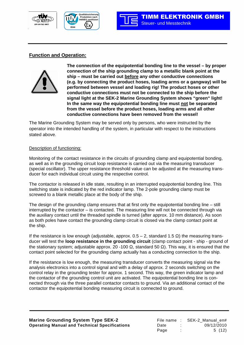
Function and Operation:
The connection of the equipotential bonding line to the vessel – by proper connection of the ship grounding clamp to a metalli c blank point at the ship – must be carried out before any other conductive connections (e.g. by connecting the product hoses, loading arms or a gangway) will be performed between vessel and loading rig! The produ ct hoses or other conductive connections must not be connected to the ship before the signal light at the SEK-2 Marine Grounding System s hows “green“ light! In the same way the equipotential bonding line must not be separated from the vessel before the product hoses, loading a rms and all other conductive connections have been removed from the v essel!
The Marine Grounding System may be served only by persons, who were instructed by the operator into the intended handling of the system, in particular with respect to the instructions stated above.
Description of functioning:
Monitoring of the contact resistance in the circuits of grounding clamp and equipotential bonding, as well as in the grounding circuit loop resistance is carried out via the measuring transducer (special oscillator). The upper resistance threshold value can be adjusted at the measuring trans-ducer for each individual circuit using the respective control.
The contactor is released in idle state, resulting in an interrupted equipotential bonding line. This switching state is indicated by the red indicator lamp. The 2-pole grounding clamp must be screwed to a blank metallic place at the body of the ship.
The design of the grounding clamp ensures that at first only the equipotential bonding line – still interrupted by the contactor – is contacted. The measuring line will not be connected through via the auxiliary contact until the threaded spindle is turned (after approx. 10 mm distance). As soon as both poles have contact the grounding clamp circuit is closed via the clamp contact point at the ship.
If the resistance is low enough (adjustable, approx. 0.5 – 2, standard 1.5 Ω) the measuring trans-ducer will test the loop resistance in the grounding circuit (clamp contact point - ship - ground of the stationary system; adjustable approx. 20 -100 Ω, standard 50 Ω). This way, it is ensured that the contact point selected for the grounding clamp actually has a conducting connection to the ship.
If the resistance is low enough, the measuring transducer converts the measuring signal via the analysis electronics into a control signal and with a delay of approx. 2 seconds switching on the control relay in the grounding tester for approx. 1 second. This way, the green indicator lamp and the contactor of the grounding control unit are activated. The equipotential bonding line is con-nected through via the three parallel contactor contacts to ground. Via an additional contact of the contactor the equipotential bonding measuring circuit is connected to ground.
Marine Grounding System Type SEK-2 File name : SEK-2_Manual_en# Operating Manual and Technical Specifications Date : 09/12/2010 Page : 6 (12)
0044
Qualitätssicherung Produktion nach
94/9/EG zertifiziert
Steuer- und MesstechnikTIMM ELEKTRONIK GMBH
The equipotential bonding measuring current flows between the common black line of the measur-ing transducer (at the contactor terminal 1), via the contactor contacts (terminals 1, 3, 5 – 2, 4, 6), the equipotential bonding line, the equipotential bonding connection, the contactor auxiliary contact (terminals 7 - 8), the fuse F2, and the brown line of the measuring transducer. If the resistance of the equipotential bonding circuit is low enough (adjustable approx. 0.5 - 2, standard 1.5 Ω) the control relay of the grounding tester is switched on permanently by the control electronic of the measuring transducer and subsequently the contactor of the grounding control unit.
If the resistance in the equipotential bonding measuring circuit exceeds the permitted value (e.g. due to excessive contact resistance at the terminals or contactor contacts), the control relay and hence the contactor will be released again at a delay of approx. 1 second. This process is re-peated again so that a permanent switching is generated indicated by the red and green indicator lamp as flashing cycle (approx. 1 second per cycle).
For more control functions (such as lock of a pump) a potential free changeover contact (230 V AC, 4 A) is provided at the grounding tester. If the periodic switching of the changeover contact in case of improper grounding is not suitable for downstream control this can be compensated for using a downstream time relay with a response delay and release delay of approx. 2 seconds.
When loosening the grounding clamp at first only the measuring line is interrupted by the auxiliary contact which is now leading resulting in release of the contactor and in interruption of the equipo-tential bonding line. Only when further loosening the grounding clamp the contact will be inter-rupted completely. This state is indicated by the red indicator lamp.
Grounding line:
When using a potential equalization line of more than 20 m length, the cable must be completely winded down for the perfect function of the system. The cable should be always used in its complete length, without partial lengths are still rolled up in loops during operation.
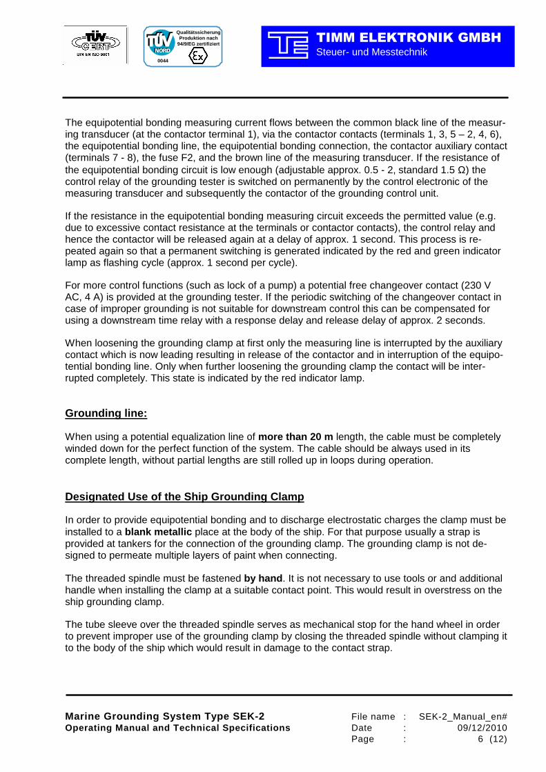
Designated Use of the Ship Grounding Clamp
In order to provide equipotential bonding and to discharge electrostatic charges the clamp must be installed to a blank metallic place at the body of the ship. For that purpose usually a strap is provided at tankers for the connection of the grounding clamp. The grounding clamp is not de-signed to permeate multiple layers of paint when connecting.
The threaded spindle must be fastened by hand . It is not necessary to use tools or and additional handle when installing the clamp at a suitable contact point. This would result in overstress on the ship grounding clamp.
The tube sleeve over the threaded spindle serves as mechanical stop for the hand wheel in order to prevent improper use of the grounding clamp by closing the threaded spindle without clamping it to the body of the ship which would result in damage to the contact strap.
Marine Grounding System Type SEK-2 File name : SEK-2_Manual_en# Operating Manual and Technical Specifications Date : 09/12/2010 Page : 7 (12)
0044
Qualitätssicherung Produktion nach
94/9/EG zertifiziert
Steuer- und MesstechnikTIMM ELEKTRONIK GMBH
In case of damage to the ship grounding clamp due t o non-compliance with the designated use, the warranty will terminate.
Instructions for Adjusting the EKOM-3 Measuring Tra nsducer:
The break-over points of the measuring transducer are tuned by factory settings and will usually not require re-adjustment (pre-set values: grounding clamp and equipotential bonding circuit 1.5 Ω each, grounding loop resistance 50 Ω). This means that the resistance in the respective circuit must not be above the value set in order to effect a release signal.
For re-adjustment the measuring transducer type EKO M-3 must be opened.
The setting range for the grounding clamp circuit and the range for the equipotential bonding circuit for both is approx. 0.2 - 2 Ω and for the grounding loop circuit approx. 20 - 100 Ω. In order to ease the setting of the switching point of the measuring transducer, LEDs are provided above the respective controls. Via the LEDs undelayed signal change of the respective threshold value contact is shown.
For easy tuning to the standard settings the respective adjusting resistances (grounding clamp circuit and equipotential bonding circuit 1.5 Ω each, grounding loop resistance 50 Ω) are al-ready integrated in the measuring transducer. The respective connection is generated by a wire bridge connection at a terminal strip in the measuring transducer.
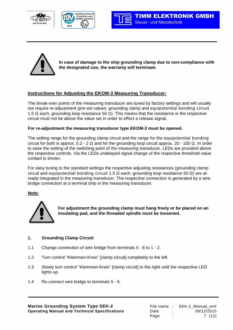
Note:
For adjustment the grounding clamp must hang freely or be placed on an insulating pad, and the threaded spindle must be lo osened.
1. Grounding Clamp Circuit:
1.1 Change connection of wire bridge from terminals 5 - 6 to 1 - 2.
1.2 Turn control "Klemmen-Kreis" [clamp circuit] completely to the left.
1.3 Slowly turn control "Klemmen-Kreis" [clamp circuit] to the right until the respective LED lights up.
1.4 Re-connect wire bridge to terminals 5 - 6.

Marine Grounding System Type SEK-2 File name : SEK-2_Manual_en# Operating Manual and Technical Specifications Date : 09/12/2010 Page : 8 (12)
0044
Qualitätssicherung Produktion nach
94/9/EG zertifiziert
Steuer- und MesstechnikTIMM ELEKTRONIK GMBH
2. Equipotential Bonding Circuit:
2.1 Change connection of wire bridge from terminals 5 - 6 to 1 - 3.
2.2 Turn control "PA-Kreis" [equipotential bonding circuit] completely to the left.
2.3 Slowly turn control "PA-Kreis" [equipotential bonding circuit] to the right until the respective LED lights up.
2.4 Re-connect wire bridge to terminals 5 - 6.
3. Grounding Circuit:
3.1 Change connection of wire bridge from terminals 5 - 6 to 2 - 4.
3.2 Turn control " Erdungs-Kreis" [grounding circuit] completely to the left.
3.3 Slowly turn control " Erdungs-Kreis" [grounding circuit] to the right until the respective LED lights up.
3.4 Re-connect wire bridge to terminals 5 - 6.

Marine Grounding System Type SEK-2 File name : SEK-2_Manual_en# Operating Manual and Technical Specifications Date : 09/12/2010 Page : 9 (12)
0044
Qualitätssicherung Produktion nach
94/9/EG zertifiziert
Steuer- und MesstechnikTIMM ELEKTRONIK GMBH
Technical Specifications: Measuring transducer type EKOM-3
(for clamp circuit, grounding circuit, and equipotential bonding circuit)
Explosion protection : EEx ib IIB T4 Measuring current in grounding clamp : EEx ib IIB
circuit Grounding cable : 20 m Neoprene cable 4 x 10 mm², 3 wires parallel = 30 mm² as equipotential bonding line
as well as 1 wire as measuring line Special grounding clamp : V2A steel with integrated, lagging auxiliary
contact for connection of measuring line Grounding tester (type EKT-3)
Explosion protection : EEx qe [ib] IIB T4 Power supply : 230 V AC, 50-60 Hz, approx. 3 VA
potential-free changeover contact (cl. 14 - 16) : max. 250 V, 3 A at cosϕ ≥≥≥≥ 0.7, or
max. 250 V, 5 A, 100 VA at cosϕ = 1
Grounding control unit type ESE-3
with contactor for equipotential bonding line Explosion protection : EEx de IIB T6
Exciting voltage : 230 V AC, 50 Hz, approx.1 VA max. values for each contact : 25 V, 15 A, 150 W Built-in type indicator lamps "red" and "green"
Explosion protection : EEx de IIC T6 Power supply : 230 V AC, 50-60 Hz, approx. 1.5 VA Compact switchgear cabinet of stainless steel
Housing protection type : IP 65 Dimensions : 600 x 600 x 210 mm (W x H x D) Weight without cable and clamp : 38 kg Weight with cable and clamp : 65 kg Power supply (overall system) : 230 V AC, 50 Hz, approx. 5.5 VA max. preceding fuse : 10 A Permitted ambient temperature range : -25°C to +50 °C
Marine Grounding System Type SEK-2 File name : SEK-2_Manual_en# Operating Manual and Technical Specifications Date : 09/12/2010 Page : 10 (12)
0044
Qualitätssicherung Produktion nach
94/9/EG zertifiziert
Steuer- und MesstechnikTIMM ELEKTRONIK GMBH
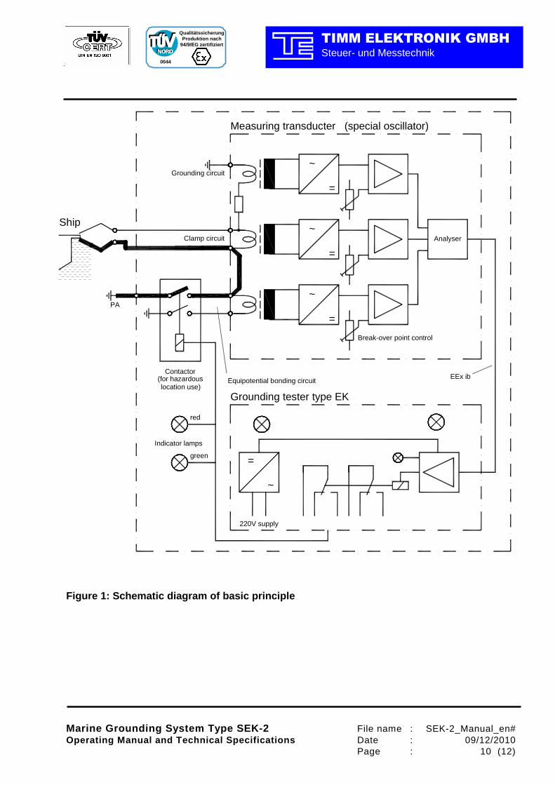
Figure 1: Schematic diagram of basic principle
Break-over point control
Grounding circuit
=
~
EEx ib
PA
green
red
Indicator lamps
Contactor
Ship
Grounding tester type EK
220V supply
=
~
~
=
=
~Analyser
Equipotential bonding circuit
Clamp circuit
Measuring transducter (special oscillator)
(for hazardouslocation use)
Marine Grounding System Type SEK-2 File name : SEK-2_Manual_en# Operating Manual and Technical Specifications Date : 09/12/2010 Page : 11 (12)
0044
Qualitätssicherung Produktion nach
94/9/EG zertifiziert
Steuer- und MesstechnikTIMM ELEKTRONIK GMBH
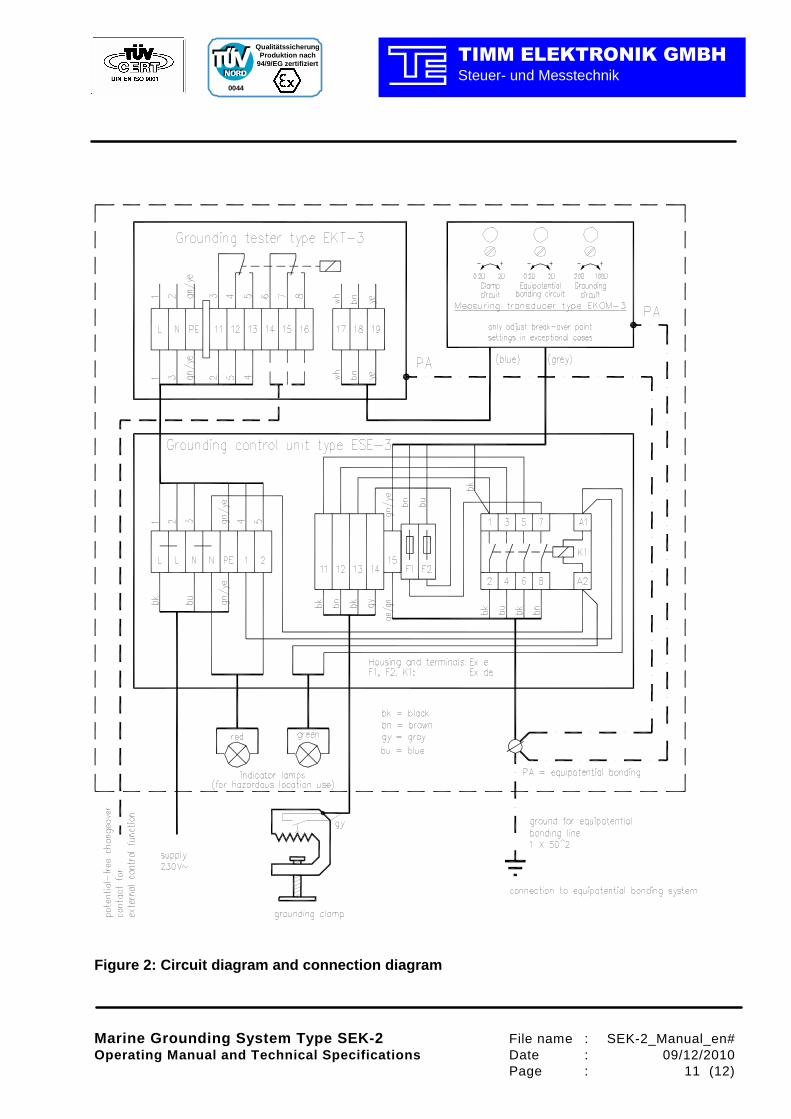
Figure 2: Circuit diagram and connection diagram

Marine Grounding System Type SEK-2 File name : SEK-2_Manual_en# Operating Manual and Technical Specifications Date : 09/12/2010 Page : 12 (12)
0044
Qualitätssicherung Produktion nach
94/9/EG zertifiziert
Steuer- und MesstechnikTIMM ELEKTRONIK GMBH
Figure 3: Dimensions
600
570
630
600
Ø8
Ext
erna
l gro
und
term
inal
Depth of unit: approx. 240mm