marine multi-component seismology in gas … library/research/oil-gas/methane... · marine...
TRANSCRIPT

CONTENTS
Marine Multi-ComponentSeismology ............................ 1
Discovery of Possible GasHydrate Features ................... 5
Monitoring Station Update ..... 8
Announcements .................. 10
• Research Cruise Completed
• Advisory Committee Meeting
• Hot Ice Project Reports
• Norway ICGH Meeting
• Simulator Publicly Released
• TOUGH-Fx/HYDRATE V 2.4
• AAPG Committee to Meet
Spotlight on Research ........ 12
Scott Dallimore
CONTACT POINT
Ray Boswell
National EnergyTechnology Laboratory
(304) 285-4541(304) 285-4216 fax
The Fire in the Ice Newsletter isalso available online at our websitewww.netl.doe.gov/scngo/NaturalGas/hydrates/index.html
T H E N A T I O N A L E N E R G Y T E C H N O L O G Y L A B O R A T O R Y M E T H A N E H Y D R A T E N E W S L E T T E R
Vol. 5, Iss. 2
○
○
○
○
○
○
○
○
○
○
○
○
○
○
○
○
○
○
○
○
○
○
○
○
○
○
○
○
○
○
○
○
○
○
○
○
○
○
○
○
○
○
○
○
○
○
○
○
○
○
○
○
○
○
○
○
○
○
○
○
○
○
○
○
○
○
○
○
○
○
1
MARINE MULTI-COMPONENT SEISMOLOGY IN GAS
HYDRATE INVESTIGATIONS ON THE NORWEGIAN
MARGIN
by Stefan Bünz1, Jürgen Mienert1, Karin Andreassen1, and Karl A.Berteussen1,2
1 Department of Geology, University of Tromsø, Tromsø, Norway2 also Petroleum Geo-Services, Houston, Texas, USA
The presence of free gas at the base of the gas hydrate stability zone underneathgas hydrates is typically identified from a characteristic bottom-simulatingreflection (BSR) on P-wave seismic data. This reflection, however, provides onlyvery little information about the hydrate-bearing sediments, making acharacterization of the micro-scale distribution of gas hydrates using P-wavedata alone ambiguous. Work carried out by researchers at the University ofTromsø has shown that the use of multi-component seismic data can permitresolution of the ambiguities that result from the acquisition of P-wave data alone.
Multi-Component SeismologyMarine multi-component seismology has gained attention in recent years due tothe development of new acquisition and processing methods. The conceptinvolves placing four-component sensing systems on the seafloor to record thefull vector wavefield of reflected energy (see figure). In essence, this meansrecording both compressional waves (P-waves) and shear waves (S-waves)using sensor packages containing hydrophones and three-component geophones.
Acquisition principle for marine multi-component seismic data. The rays illustrate how a downgoingP-wave generates an upgoing P-wave, but also converts upon reflection, creating an upgoing S-wave.
www.netl.doe.gov/scngo/NaturalGas/hydrates/index.html
Interested in contributingan article to Fire in the Ice?This newsletter now reachesnearly 500 scientists andother individuals interested inhydrates in sixteencountries. If you would like tosubmit an article about theprogress of your methanehydrates research project,please contactKarl Lang at 301-354-2033([email protected])
○
○
○
○
○
○
○
○
○
○
○
○
○
○
○
○
○
○
○
○
○
○
○
○
○
○
○
○
○
○
○
○
○
○
○
○
○
○
○
○
○
○
○
○
○
○
○
○
○
○
○
○
○
○
○
○
○
○
○
○
○
○
○
○
○
○
○
○
○
○
○
○
○
○
○
○
○
○
○
○
○
○
○
○
○
○
INTENT
Fire in the Ice is published bythe National EnergyTechnology Laboratory topromote the exchange ofinformation among thoseinvolved in gas hydratesresearch and development.
2
Conventional marine-towed streamer systems that are one-componentsystems, use only hydrophones and therefore record only P-waves. Multi-component systems, while more expensive, also allow recording of S-waves. Inthe case of marine multi-component seismic data, two ships are often used.One ship deploys the 4-component system while another ship tows a P-wavesource. Both P- and S-waves are recorded by sensor packages that includeone hydrophone, a vertical geophone and two horizontal geophones orientedperpendicular to each other. All four are included in each receiver group. Thisapproach provides more acoustic information about the properties of rocks andfluids than is obtained by recording only one component. S-waves aregenerated from P-waves impinging on lithologic boundaries with different rockproperties. Such wave types are called converted waves (C-waves) or PS-waves.
A P-wave that propagates through rock is affected by both the rock matrix andthe pore fluids. When an S-wave passes through rock, its behavior is affectedmainly by the matrix of the rock and only to a very minor degree by the porefluids. Another important property of S-waves is that they are much slower thanP-waves (up to 8 – 10 times slower in the shallow subsurface). Combininginformation from S-waves with that obtained from P-waves gives a much morecomplete interpretation of a reservoir.
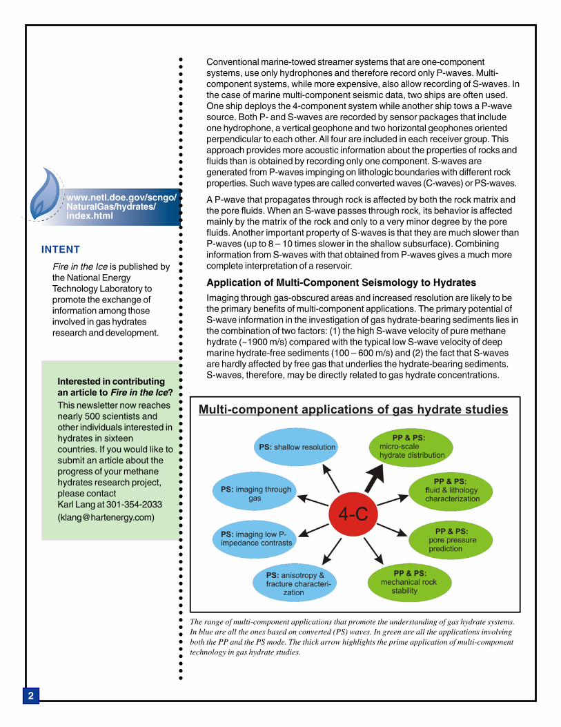
Application of Multi-Component Seismology to HydratesImaging through gas-obscured areas and increased resolution are likely to bethe primary benefits of multi-component applications. The primary potential ofS-wave information in the investigation of gas hydrate-bearing sediments lies inthe combination of two factors: (1) the high S-wave velocity of pure methanehydrate (~1900 m/s) compared with the typical low S-wave velocity of deepmarine hydrate-free sediments (100 – 600 m/s) and (2) the fact that S-wavesare hardly affected by free gas that underlies the hydrate-bearing sediments.S-waves, therefore, may be directly related to gas hydrate concentrations.
The range of multi-component applications that promote the understanding of gas hydrate systems.In blue are all the ones based on converted (PS) waves. In green are all the applications involvingboth the PP and the PS mode. The thick arrow highlights the prime application of multi-componenttechnology in gas hydrate studies.

○
○
○
○
○
○
○
○
○
○
○
○
○
○
○
○
○
○
○
○
○
○
○
○
○
○
○
○
○
○
○
○
○
○
○
○
○
○
○
○
○
○
○
○
○
○
○
○
○
○
○
○
○
○
○
○
○
○
○
○
○
○
○
○
○
○
○
○
○
○
○
○
○
○
○
○
○
○
○
○
○
○
○
○
○
○
3
The primary application of multi-component data in hydrate studies is toresolve the micro-scale distribution of gas hydrates within sediments, that is,to determine if hydrates are disseminated within the pore space or if thehydrates cement grain contacts (see figure). The presence of cementinghydrates would increase the rigidity of the sediments, which in turn would leadto an increase in S-wave velocity. Furthermore, S-waves provide a much clearerimage of sediment stratigraphy and subsurface structure as they areunaffected by the presence of gas that occurs underneath the hydrate-bearingsediments and thus offer a much better seismic resolution. Other usefulapplications in hydrate settings involve imaging of low P-wave impedancecontrasts, anisotropy and fracture characterization, fluid and lithologycharacterization, pore pressure prediction and mechanical rock analysis.These last two applications are important as gas hydrates are a known drillinghazard and widely considered to be involved in slope instabilities.
Multi-Component Investigation of Hydrates on Norwegian MarginThroughout the last six years the Department of Geology of the University ofTromsø has spent substantial amounts of time investigating the gas hydrateson the Norwegian Margin using multi-component seismic data. Much of this hasbeen fostered by the fact that Petroleum Geo-Services, Oslo, has acquired a4-km long multi-component ocean-bottom cable (OBC) seismic line in an areawith hydrate-bearing sediments (see figure). That OBC line was subsequentlymade available to our group at the University of Tromsø. In addition to the OBCline, we have acquired data from up to 100 ocean-bottom seismometer (OBS)stations at locations where conventional P-wave seismic data provided evidencefor the presence of gas hydrates or free gas within the sediments.
The OBC line was the first ever acquired over a gas hydrate-related BSR. Theseismic data are of very good quality, and display strong P-S converted wavereflections for the whole sediment column (see figure). S-wave reflections mainlyresult from stratigraphic boundaries, where an S-wave impedance contrastexists, and thus the mode-converted waves yield direct and more accurateinformation about the shear properties of the subsurface. Due to the fact that
Map showing thedistribution of the BSR onthe mid-Norwegian marginand the coverage of multi-component data in this area.In addition, there are about40 OBS stations on thewestern Svalbard margin.

○
○
○
○
○
○
○
○
○
○
○
○
○
○
○
○
○
○
○
○
○
○
○
○
○
○
○
○
○
○
○
○
○
○
○
○
○
○
○
○
○
○
○
○
○
○
○
○
○
○
○
○
○
○
○
○
○
○
○
○
○
○
○
○
○
○
○
○
○
○
○
○
○
○
○
○
○
○
○
○
○
○
○
○
○
○
4
the S-wave velocity is much lower than the P wave velocity, the seismicresolution increases and the inline component of the OBC survey provides amuch more detailed image of the subsurface. Improved acoustic images allowus to look through the zone underneath the hydrate-bearing sediments, whichis obscured on the P-wave data due to the occurrence of gas.
The P-wave component shows a clear BSR about 350 ms underneath theseafloor reflection. No P-S reflections are associated with the BSR along thisline, indicating that the gas hydrate-bearing sediments at the base of thehydrate stability zone are not stiff enough to increase the shear modulus of thesediments to produce P-S converted wave reflections. The observations onboth P-wave and PS-wave components of the OBC line favor a model in whichgas hydrates are disseminated within the pore space. This is corroborated byP- and S-wave velocities derived from OBS data from the same area. The multi-component data has further allowed us to resolve ambiguities that would existusing the P-wave data alone. For example, above the Ormen Lange deep-watergas reservoir, OBS data is able to provide an unambiguous interpretation of thesubsurface structure, thereby distinguishing between lithologic effects and theeffects that occur in the presence of gas hydrates or free gas.
At the moment, our main effort is directed towards understanding the dynamicsof the free gas system. To this end we are assessing the pore pressuredistribution within the hydrate/free-gas system using the OBC line. Moreover, incooperation with a group from the Istituto Nazionale di Oceanografia e diGeofisica Sperimentale (OGS), in Trieste, Italy, we are applying tomographictraveltime inversion to an array of data from 21 OBSs to obtain a three-dimensional velocity volume. This volume will be integrated with three-dimensional seismic interpretation, which will allow us to investigate therelationship between subsurface fluid conduits and the free gas zoneunderneath the hydrates. It is aimed towards improving our understanding ofthe interaction of gas-laden fluids with the subsurface structure, and thehydrate and gas accumulation mechanisms.
Stacked sections of P-wave and the PS-wave component of the OBC line, which has a length ofapproximately 4 km. Note the difference in time axis. The inline component has been linearlystretched in time to match the P wave data based on a horizon, which occurs just below asedimentary layer with chaotic internal texture labeled “seismic unconformity.”
SUGGESTED READING
Bünz, S., J. Mienert, and C.Berndt, Geological controls onthe Storegga gas-hydratesystem of the mid-Norwegiancontinental margin, EarthPlanet. Sci. Lett., 209, 291–307, 2003.
Andreassen, K., K. A.Berteussen, H. Sognnes, K.Henneberg, J. Langhammer,and J. Mienert,Multicomponent ocean bottomcable data in gas hydrateinvestigation offshore ofNorway, J. Geophys. Res.,108(B8), 2399, 2003.
Bünz, S., and J. Mienert,Acoustic imaging of gashydrate and free gas at theStoregga Slide, J. Geophys.Res., 109, B04102, 2004.
Mienert, J., S. Bünz, S.Guidard, M. Vanneste, C.Berndt, Ocean-bottomseismometer investigations inthe Ormen Lange areaoffshore Mid- Norway provideevidence for shallow gaslayers in subsurface sediments,Mar. Petr. Geol., in press.

○
○
○
○
○
○
○
○
○
○
○
○
○
○
○
○
○
○
○
○
○
○
○
○
○
○
○
○
○
○
○
○
○
○
○
○
○
○
○
○
○
○
○
○
○
○
○
○
○
○
○
○
○
○
○
○
○
○
○
○
○
○
○
○
○
○
○
○
○
○
○
○
○
○
○
○
○
○
○
○
○
○
○
○
○
○
5
DISCOVERY OF POSSIBLE GAS HYDRATE
FEATURES OFFSHORE NORWAY
by Martin Hovland, Statoil, Stavanger, Norway
A detailed seabed survey carried out in March 2003 at the Nyegga region ofthe continental slope off the coast of Norway discovered a rugged seafloorterrain that included a large complex of pockmarks with thick internal pilesof carbonate rocks and soft, fluid-generating pingo-like structuressuspected of containing gas hydrates.
The Nyegga region is located at a water depth of about 750 m on thenorthern flank of the well-known Storegga submarine slide, which occurredabout 7200 years ago. In this region, bottom-simulating reflectors (BSRs) arewell known features, together with pockmarks and suspected mud diapirsfirst reported over 20 years ago. Statoil conducted two surveys in the Nyeggaregion and has discovered evidence of locally dynamic sediments, much likethose found in terrestrial freeze/thaw locations.
The rugged features known as “complex pockmarks” can be seen on animage produced by multibeam echosounding carried out from the ROVHirov deployed from the survey vessel Normand Tonjer (see figure). Photostaken by that Hirov inside the G11 complex pockmark show largecarbonate rocks that are suspected to have formed sub-surface andsubsequently been pushed upwards, either by freeze-thaw processes or bythe expulsion of gas.
A close-up of the seabed near one of these large carbonate blocks revealsa conical mound that appears to be a pingo-like structure (see photos).Commonly found in Arctic permafrost regions, a pingo is a geologicalfeature caused by hydrostatic pressure that develops as underground iceexpands. The features observed offshore Norway are covered by carpets ofsmall tubeworms. The white blotches are mats of bacteria that grow wherewater and gas seep out of the ground, possibly above dissociating hydrateor melting ice inside the mound.
Echosound image of the Nyegga site with vertical scale enhanced by a factor of three. The pockmarknamed “G11” has a diameter of about 150 m and is the primary study location.
○
○
○
○
○
○
○
○
○
○
○
○
○
○
○
○
○
○
○
○
○
○
○
○
○
○
○
○
○
○
○
○
○
○
○
○
○
○
○
○
○
○
○
○
○
○
○
○
○
○
○
○
○
○
○
○
○
○
○
○
○
○
○
○
○
○
○
○
○
○
○
○
○
○
○
○
○
○
○
○
○
○
○
○
○
○
6
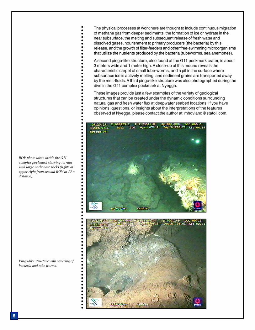
The physical processes at work here are thought to include continuous migrationof methane gas from deeper sediments, the formation of ice or hydrate in thenear subsurface, the melting and subsequent release of fresh water anddissolved gases, nourishment to primary producers (the bacteria) by thisrelease, and the growth of filter-feeders and other free-swimming microorganismsthat utilize the nutrients produced by the bacteria (tubeworms, sea anemones).
A second pingo-like structure, also found at the G11 pockmark crater, is about3 meters wide and 1 meter high. A close-up of this mound reveals thecharacteristic carpet of small tube-worms, and a pit in the surface wheresubsurface ice is actively melting, and sediment grains are transported awayby the melt-fluids. A third pingo-like structure was also photographed during thedive in the G11 complex pockmark at Nyegga.
These images provide just a few examples of the variety of geologicalstructures that can be created under the dynamic conditions surroundingnatural gas and fresh water flux at deepwater seabed locations. If you haveopinions, questions, or insights about the interpretations of the featuresobserved at Nyegga, please contact the author at: [email protected].
ROV photo taken inside the G11complex pockmark showing terrainwith large carbonate rocks (lights atupper right from second ROV at 15 mdistance).
Pingo-like structure with covering ofbacteria and tube worms.
7
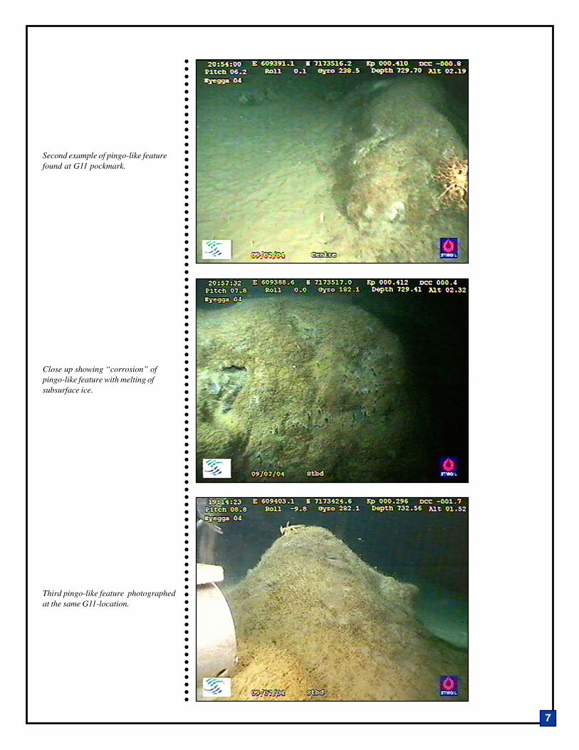
Second example of pingo-like featurefound at G11 pockmark.
Close up showing “corrosion” ofpingo-like feature with melting ofsubsurface ice.
Third pingo-like feature photographedat the same G11-location.
○
○
○
○
○
○
○
○
○
○
○
○
○
○
○
○
○
○
○
○
○
○
○
○
○
○
○
○
○
○
○
○
○
○
○
○
○
○
○
○
○
○
○
○
○
○
○
○
○
○
○
○
○
○
○
○
○
○
○
○
○
○
○
○
○
○
○
○
○
○
○
○
○
○
○
○
○
○
○
○
○
○
○
○
○
○
○
○
○
○
○
○
○
○
○
○
○
○
○
○
○
○
○
○
○
○
○
○
○
○
○
○
○
○
○
○
○
○
○
○
○
○
○
○
○
○
○
○
○
○
○
○
○
○
○
○
○
○
○
○
○
○
○
○
○
○
○
○
○
○
○
○
○
○
○
○
○
○
○
○
○
○
○
○
○
○
○
○
○
○
○
○
8
MISSISSIPPI CANYON BLOCK 118 SEAFLOOR-MONITORING STATION UPDATE
by Carol Lutken, Center for Marine Resources and Environmental Technologyat the University of Mississippi
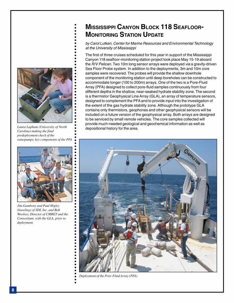
The first of three cruises scheduled for this year in support of the MississippiCanyon 118 seafloor-monitoring station project took place May 15-19 aboardthe R/V Pelican. Two 10m long sensor arrays were deployed via a gravity-drivenSea Floor Probe system. In addition to the deployments, 3m and 10m coresamples were recovered. The probes will provide the shallow downholecomponent of the monitoring station until deep boreholes can be constructed toaccommodate longer (100 to 200m) arrays. One of the two is a Pore-FluidArray (PFA) designed to collect pore-fluid samples continuously from fourdifferent depths in the shallow, near-seabed hydrate stability zone. The secondis a thermistor Geophysical Line Array (GLA), an array of temperature sensors,designed to complement the PFA and to provide input into the investigation ofthe extent of the gas hydrate stability zone. Although the prototype GLAcontains only thermistors, geophones and other geophysical sensors will beincluded on a future version of the geophysical array. Both arrays are designedto be serviced by small remote vehicles. The core samples collected willprovide much-needed geological and geochemical information as well asdepositional history for the area.
Deployment of the Pore-Fluid Array (PFA)
Laura Lapham (University of NorthCarolina) making the finalpredeployment check of theosmopumps, key components of the PFA
Jim Gambony and Paul Higley(kneeling) of SDI, Inc. and BobWoolsey, Director of CMRET and theConsortium, with the GLA, prior todeployment.

○
○
○
○
○
○
○
○
○
○
○
○
○
○
○
○
○
○
○
○
○
○
○
○
○
○
○
○
○
○
○
○
○
○
○
○
○
○
○
○
○
○
○
○
○
○
○
○
○
○
○
○
○
○
○
○
○
○
○
○
○
○
○
○
○
○
○
○
○
○
○
○
○
○
○
○
9
Additional cruises during September-October 2005 will be focused on surveyingthe seafloor to determine precisely where additional components of themonitoring station should be located. In addition, we will deploy additionalsensor systems, connect components, run a seismic survey to test the dataretrieval system, and collect and replace sample coils on the geochemicalprobe deployed in May.
Deployment of additional elements will be carried out during 2006. The Stationhas evolved since its original conception, primarily in response to changingcircumstances and advances in technology. The geophysical sensor systemconcept now calls for a single water-column acoustic line array (ALA) locatedin close proximity to four horizontal arrays (HLAs) laid out in a cross pattern onthe seabed (see figures). Plans include gaining access to one or moreboreholes for the installation of at least one borehole vertical line array (BLA),as well as alternative concepts for geophysical sensing. Geochemical sensorsinclude components to be suspended in the water column, as well as those onthe sea floor in the subsurface. A number of Station Support Systems (SSS)continue to be developed for the installation, operation, and maintenance of thestation.
The seafloor monitoring station is being developed by the Center for MarineResources and Environmental Technology (CMRET) at the University ofMississippi through the Gulf of Mexico Hydrates Research Consortium. TheConsortium is comprised of researchers from around the world and includesuniversity, industry and government participants. Support for the project isprovided by the Minerals Management Services (DOI-MMS), the NationalEnergy Technology Laboratory (DOE-NETL), and the National Institute forUndersea Science and Technology (NOAA-NIUST). The elements of the stationthat are designed to be deployed during 2005 and 2006, are shown in thegraphics included here and identified according to the sponsoring organization.
For a more complete description of the goals and purpose of the observatory,please refer to the article published in the Summer 2004 issue of Fire in the Iceavailable online at http://www.netl.doe.gov/scngo/NaturalGas/hydrates/index.html/.

○
○
○
○
○
○
○
○
○
○
○
○
○
○
○
○
○
○
○
○
○
○
○
○
○
○
○
○
○
○
○
○
○
○
○
○
○
○
○
○
○
○
○
○
○
○
○
○
○
○
○
○
○
○
○
○
○
○
○
○
○
○
○
○
○
○
○
○
○
○
○
○
○
○
○
○
○
○
○
○
○
○
○
○
○
○
10
Announcements
RESEARCH CRUISE COMPLETED INTHE GULF OF MEXICO
Between April 17 and May 21 the semi-submersible drilling vessel Uncle Johncarried out a 35-day research voyage for the ChevronTexaco Gulf of Mexicohydrates joint industry project (JIP). During the expedition, researcherscollected drilling, logging, and coring data from wells drilled at locations in theKeathley Canyon and Atwater Valley blocks, to characterize methane hydratesin the deepwater Gulf.
A total of four wells were drilled at the Atwater Valley Blocks 13 and 14. Thefirst two wells were logged-while-drilling and coring operations were carried outat the second two locations. One of these two was successfully logged aswell. Three wells were drilled at Keathley Canyon: two were evaluated withlogging-while-drilling and a third via coring. Surface push cores and a variety ofother data were collected at both sites.
A special section of the SCNGO website provided background projectinformation, scientific objectives, status reports, scientific updates, andpictures as they were made available. The direct link to the NETL-JIP Cruisewebsite is: http://www.netl.doe.gov/scngo/NaturalGas/hydrates/index.html/.
All coring and logging activities were concluded and the Uncle John hasreturned safely to port. Post-cruise analysis of the cores and logs is underway.As results are obtained they will be posted on the National Methane HydrateR&D Program website.
ADVISORY COMMITTEE MEETING
On June 7-8, the Methane Hydrate Advisory Committee, a 10 member advisorycommittee to the Secretary of Energy, met in Galveston, TX. Topics for discussionincluded: research updates (especially the Joint Industry Project Gulf of Mexicodrilling), future program directions, and changes in advisory committee structure.DOE also hosted a meeting of the Interagency Coordinating Committee concurrentwith the first morning of the Advisory Committee meeting. Jim Slutz, DAS for Oiland Natural Gas, was named the Designated Federal Official for this meeting.Besides Advisory Committee members, attendees included DOE programmanagers and industry representatives. Interagency Coordinating Committeeparticipants included representatives from the National Oceanic and AtmosphericAdministration, Naval Research Lab, U.S. Geological Survey, MineralsManagement Service, National Science Foundation, and the Department of State.
HOT ICE PROJECT REPORTS AVAILABLE
Five topical reports and the final report from the Hot Ice project are nowavailable in the National Methane Hydrate R&D Program Library on the NETLwebsite. Go to http://www.netl.doe.gov/scngo/NaturalGas/hydrates/index.html,click on “Methane Hydrate Library,” then “Publications,” then “Project Reports”from the choices on the right. The Hot Ice project was a cost-shared effortbetween DOE, Maurer Technology Inc., Anadarko Petroleum Corp., and NobleCorp. to develop technology and to drill and test a dedicated hydrate well onthe North Slope of Alaska.
Example of the transfer of a hydraulicpiston core into the core processing van
A pressure core on ice awaitingtransfer to the van.

○
○
○
○
○
○
○
○
○
○
○
○
○
○
○
○
○
○
○
○
○
○
○
○
○
○
○
○
○
○
○
○
○
○
○
○
○
○
○
○
○
○
○
○
○
○
○
○
○
○
○
○
○
○
○
○
○
○
○
○
○
○
○
○
○
○
○
○
○
○
○
○
○
○
○
○
○
○
○
○
○
○
○
○
○
○
11
NORWAY ICGH MEETING
The Fifth International Conference on Gas Hydrates (ICGH 5) will take place atthe Royal Garden Hotel in Trondheim, Norway, on June 13-16. It is expectedthat more than 300 flow assurance and gas hydrate specialists from around theworld will be in attendance to witness 24 oral presentations and 220 posterpresentations. The conference is organized around the following five topicalsessions: Kinetics and Transport Phenomena; Structure and PhysicalProperties; Exploration, Resources and Environment; Industrial Applicationsand; Thermodynamic Aspects. Details and registration are available on theConference website at http://www.icgh.org/.
RESERVOIR SIMULATOR PUBLICLY RELEASED
LBNL’s hydrate reservoir simulator (TOUGH-Fx/HYDRATE v1.0) is now publiclyavailable for licensing. TOUGH-Fx/HYDRATE models non-isothermal gasrelease, phase behavior and flow of fluids and heat in complex geologic media.The code can simulate production from natural methane hydrate deposits inpermafrost and in deep ocean sediments, as well as laboratory experiments ofhydrate dissociation/formation in porous/fractured media. TOUGH-Fx/HYDRATE v1.0 includes both an equilibrium and a kinetic model of hydrateformation and dissociation. For more information about the model and how toobtain a license, please visit http://www.netl.doe.gov/scngo/Natural%20Gas/hydrates/index.html and select “FWP-G308” from the lefthand menu “DOEProjects” list or contact: Seth Rosen, Senior Licensing Associate, TechnologyTransfer Department, Lawrence Berkeley National Laboratory, Phone (510)486-4303 or vial e-mail ([email protected]).
PETRASIM V2.4 FOR TOUGH-FX/HYDRATEPetraSim Version 2.4 - is an interactive preprocessor and postprocessor tool torapidly develop models and view results for TOUGH-Fx/HYDRATE. PetraSimVersion 2.4 can be downloaded for a free 30 day trial at: www.petrasim.com.Example input, output, and manual files can be downloaded at: http://www.thunderheadeng.com/petrasim/help/tough/examples.htm . For additionalinformation please contact Thunderhead Engineering at: ThunderheadEngineering Consultants, Inc., 1006 Poyntz Ave., Manhattan, KS 66502-5459,Phone (785) 770-8511 (or via e-mail at [email protected]).
COMMITTEE TO MEET DURING AAPG CONVENTION
During this year’s annual AAPG convention in Calgary, a meeting of the EnergyMinerals Division’s Gas Hydrate Committee has been scheduled for Tuesdayevening, June 21, from 5:30 to 8:00 pm at the Hyatt Regency (Imperial Rooms1 and 2). Several presentations are planned that focus on recent developmentsin the gas hydrate field. In addition, plans will be made for additional activitiesby the committee and its members. Individuals interested in attending shuldcontact Committee Chair Art Johnson at [email protected]/.
Announcements

○
○
○
○
○
○
○
○
○
○
○
○
○
○
○
○
○
○
○
○
○
○
○
○
○
○
○
○
○
○
○
○
○
○
○
○
○
○
○
○
○
○
○
○
○
○
○
○
○
○
○
○
○
○
○
○
○
○
○
○
○
○
○
○
○
○
○
○
○
○
○
○
○
○
○
○
○
○
○
○
○
○
○
○
○
○
12
ARCTIC HYDRATES–AN ENGINEER’S INTEREST
In a methane hydrate research community dominated by geologists,geophysicists and geochemists, it’s always worthwhile to hear from theengineers’ side of the aisle. Scott Dallimore has found his past work as ageotechnical engineer working on permafrost engineering problems very usefulfor gas hydrate research; many of the properties of gas hydrates in sedimentsare similar to those of ice in permafrost. And like most engineers, Scott becamehooked on the science while trying to solve a practical problem: how tosuccessfully carry out a Geological Survey of Canada drilling program aimed atcollecting deep core samples of permafrost in the Mackenzie Delta. “The GSCprogram in 1992 was a collaborative effort with Shell Canada and Imperial Oil.While drilling a hole at the Taglu well site we encountered both free gas andvisible gas hydrates within the permafrost itself. We had a very exciting timesorting out the science on the spot,” recounts Scott. This event led Dallimoreand his GSC colleagues to seek out others engaged in Arctic hydrate researchin the United States and Russia.
One thing that fascinates Scott about methane hydrates is the fact that muchof the work done in the field is new science. “Every time a new drilling programis conducted we are undertaking frontier exploration research anddevelopment.” While most of his expertise and experience has been in thenorth, Dallimore remains very interested in the progress being made in marinegas hydrates research. “The scale and intensity of recent Japanese activity inthe Nankai Trough is impressive, and the accomplishments of several majorODP gas hydrate studies, such as Legs 164 and 204, are really quiteremarkable,” observes Dalilimore. Scott has a small role in a new IODPExpedition planned for the Cascadia margin this fall, which he hopes will yieldyet more exciting new methane hydrate science.
Dallimore feels fortunate to have been able to play a role in a number of largeintegrated Arctic field programs that approach the IODP expeditions in scope. Indesigning these programs Scott has tried to incorporate lessons learned fromthe IODP experience, adapting them to the logistics and technical challenges ofthe Arctic. He points out the fact that these Arctic programs have taken on thechallenge of pursuing both fundamental and applied research goals. “The Mallik2002 production research well program has been our most challenging effort todate,” states Dallimore. “Beyond the fact that we achieved our objective ofcollecting the first well-constrained data set on the production response of gashydrates, I am very proud of the fact that we did it with a multidisciplinaryscience approach. Our soon-to-be-released scientific results volume includes 62papers—more than 150 co-authors and almost a thousand pages of text, as wellas a comprehensive database.” Scott points out that the Mallik 2002 programwas made possible by partners from Japan, USA, Germany, India and Canada,all of whom assumed substantial risks to enable the project to move forward.
Dallimore is optimistic about the future potential of gas production from methanehydrate deposits. “If we can maintain the pace of research and development thatwe have seen in the past five years, I fully expect that production of gashydrates will become a reality in the next 15 to 20 years, possibly sooner. Iexpect that first production will be from an Arctic region of Alaska, Canada orRussia, where we have identified concentrated gas hydrate deposits lying abovedeeper conventional oil and gas fields. However, programs such as thoseunderway in Japan and planned for offshore India may surprise us.”
Scott is quick to acknowledge that he owes a great deal to one particularmarine geologist who has worked with him over the years on Arctic geologyprojects: his wife, Dr. Audrey Dallimore.
SCOTT DALLIMORE
Geological Survey of Canada,Natural Resources CanadaSidney, British [email protected]
Scott’s interest in the Arcticbegan twenty-six years agowhen he skied across BaffinIsland with five friends fromQueen’s University. The fivestill get together at RockyMountain ski resorts, wherethe chance of meeting polarbears is significantly less.