marine sapphire engineered clean-agent systems - ansul marine... · marine sapphire engineered...
TRANSCRIPT

MARINE sApphIRE ENGINEERED CLEAN-AGENT sYsTEMs
Component Sheet Library
One Stanton Street / Marinette, WI 54143-2542, USA / +1-715-735-7411 / www.ansul.comCopyright © 2014Tyco Fire Products LP. / All rights reserved. / Form No. 433036 Component Sheets_2013-JAN-25

SECTION Pages________ ______
1. COMPONENTS 1-1 – 1-52
PARTS LIST FOR ANSUL® MARINE SAPPHIRE® SYSTEMS 1-1 – 1-2.1
BLANK PAGE 1-2.2
3M™ NOVEC™ 1230 FIRE PROTECTION FLUID 1-3
AGENT TANK 1-4
TANK NAMEPLATE 1-4.1
BLANK PAGE 1-4.2
DISCHARGE VALVE ASSEMBLY 1-5
AGENT TANK BRACKETS 1-6
BRACKET CHANNEL 1-7
FLEXIBLE DISCHARGE HOSE 1-8
3 IN. DISCHARGE HOSE/CHECK VALVE ASSEMBLY 1-8.1
3 IN. DISCHARGE HOSE 1-8.1
3 IN. VALVE SINGLE TANK ADAPTORS 1-8.1
BLANK PAGE 1-8.2
MANIFOLD CHECK VALVES 1-9
BLANK PAGE 1-10
DISCHARGE NOZZLES 1-11
PNEUMATIC ACTUATOR 1-12
MANUAL ACTUATOR 1-12.1
BLANK PAGE 1-12.2
LOW PRESSURE SWITCH 1-13
CPM ACTUATOR 1-13.1
BLANK PAGE 1-13.2
NITROGEN PILOT CYLINDER 1-14
42 FT3 NITROGEN PILOT CYLINDER 1-14.1
BLANK PAGE 1-14.2
NITROGEN PILOT CYLINDER BRACKET 1-15
42 FT3 NITROGEN PILOT CYLINDER BRACKET ASSEMBLY 1-15.1
LIQUID LEVEL INDICATOR 1-15.2
PILOT VALVE LEVER RELEASE ACTUATOR 1-16
PRESSURE OPERATED STACKABLE ACTUATOR 1-17
CONNECTING LINK 1-18
MANUAL PULL BOX (LATCHED DOOR TYPE) 1-19
MANUAL PULL BOX (BREAK GLASS TYPE “A”) 1-20
TYPICAL PULL BOX INSTALLATIAON 1-20.1
BLANK PAGE 1-20.2
COMBINATION LATCH AND BREAK GLASS PULL BOX 1-21
ENCLOSED DOUBLE CABLE PULL BOX WITH MICROSWITCH 1-22
SURFACE MOUNT MANUAL PULL BOX 1-22.1
FLUSH MOUNT MANUAL PULL BOX 1-22.2
FLEXIBLE CONDUIT/CABLE KIT 1-22.3
FLEXIBLE CONDUIT/CABLE BRACKET DRAWING 1-22.4
FLEXIBLE CONDUIT/CABLE KIT DRAWING 1-22.4
CABLE WITH SWAGED END FITTING 1-23 – 1-24
CORNER PULLEY 1-25
DUAL/TRIPLE CONTROL BOXES 1-26
REMOTE CABLE PULL EQUALIZER 1-27
MARINE ACTUATION STATION – TWO STEP (S.O.L.A.S.) 1-28

SECTION Pages________ ______
1. COMPONENTS 1-1 – 1-52 MICROSWITCH MOUNTING LOCATION/MOUNTING DETAIL FOR 1-28.1 MARINE ACTUATION STATION
BLANK PAGE 1-28.2
MARINE ACTUATION STATION – ONE STEP 1-29
MICROSWITCH MOUNTING LOCATION/MOUNTING DETAIL FOR 1-29.1 MARINE ACTUATION STATION
QUARTZOID BULB ACTUATOR 1-29.2
PNEUMATIC ACTUATION LINE KIT 1-30
MALE BRANCH TEE 1-31
MALE ELBOW ADAPTOR 1-31.1
MALE CONNECTOR 1-31.2
ADAPTOR 1-31.3
MALE BRANCH TEE 1-31.4
MALE ELBOW 1-31.5
MALE ADAPTOR 1-31.6
PILOT CYLINDER FLEXIBLE DISCHARGE BEND 1-32
STAINLESS STEEL ACTUATION HOSE 1-33
BLEEDER PLUG 1-34
HEADER VENT PLUG 1-35
1/2 IN. MANIFOLD SAFETY RELIEF RUPTURE DISC ASSEMBLY 1-36
PRE-DISCHARGE TIME DELAY 1-37
29 SECOND TIME DELAY ASSEMBLY 1-37.1
BLANK PAGE 1-37.2
3/4 IN. PRESSURE ACTUATED STOP/ISOLATION VALVE 1-38
CHECK VALVES – THREADED 1-39
1/4 IN. CHECK VALVE 1-39.1
1/2 IN. BALL VALVE WITH MANUAL LOCKING DEVICE 1-39.2
1/4 IN. STOP VALVE 1-39.3
BLANK PAGE 1-39.4
GLOBE VALVES AND CONTROLS 1-40
STOP VALVES 1-41
PRESSURE-OPERATED SIREN 1-42
PRESSURE SWITCH – 3PDT 1-43
PRESSURE SWITCH DPDT – EXPLOSION-PROOF 1-44
BLANK PAGE 1-45
PRESSURE TRIP 1-46
PRESSURE TEST ASSEMBLY 1-47
OPERATING INSTRUCTIONS PLATE – PULL CABLE ACTUATION 1-48
WARNING SIGNS 1-49
NAMEPLATE – MAIN 1-50
NAMEPLATE – RESERVE 1-51
Marine SAPPHIRE Suppression System SECTION 1 – COMPONENTSUL EX-4510 USCG APPROVAL NO. 162.161/6/0
2013-JAN-25 REV. 4 PAGE 1-1
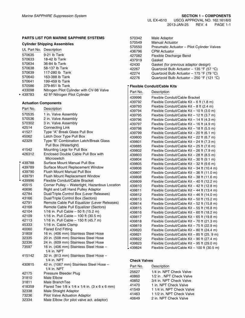
ParTS LIST fOr MarINE SaPPHIrE SySTEMS
Cylinder Shipping assemblies
UL Part No. Description570635 9-21 lb Tank570633 18-42 lb Tank570634 36-84 lb Tank570638 58-137 lb Tank570639 117-280 lb Tank570640 163-388 lb Tank570641 199-459 lb Tank570586 379-851 lb Tank433098 Nitrogen Pilot Cylinder with CV-98 Valve439783 42 ft3 Nitrogen Pilot Cylinder
actuation Components
Part No. Description
570535 1 in. Valve Assembly570536 2 in. Valve Assembly570302 3 in. Valve Assembly42514 Connecting Link41527 Type “A” Break Glass Pull Box45062 Latch Door Type Pull Box42329 Type “B” Combination Latch/Break Glass
Pull Box (Watertight)41542 Mounting Legs for Pull Box426312 Enclosed Double Cable Pull Box with
Microswitch439788 Surface Mount Manual Pull Box439789 Surface Mount Replacement Window439790 Flush Mount Manual Pull Box439791 Flush Mount Replacement Window439996 Flexible Conduit/Cable Bracket45515 Corner Pulley – Watertight, Hazardous Location40696 Right and Left Hand Pulley Adaptor42784 Dual/Triple Control Box (Lever Releases)43166 Dual/Triple Control Box (Sectors)42791 Remote Cable Pull Equalizer (Lever Releases)43168 Remote Cable Pull Equalizer (Sectors)42104 1/16 in. Pull Cable – 50 ft (15.2 m)42109 1/16 in. Pull Cable – 100 ft (30.5 m)42113 1/16 in. Pull Cable – 150 ft (45.7 m)45333 1/16 in. Cable Clamp40060 Flared End Fitting31809 16 in. (406 mm) Stainless Steel Hose32335 20 in. (508 mm) Stainless Steel Hose32336 24 in. (609 mm) Stainless Steel Hose73597 16 in. (406 mm) Stainless Steel Hose –
1/4 in. NPT415142 32 in. (813 mm) Stainless Steel Hose –
1/4 in. NPT430815 42 in. (1067 mm) Stainless Steel Hose –
1/4 in. NPT42175 Pressure Bleeder Plug31810 Male Elbow31811 Male BranchTee418359 Flared Tee 1/8 x 1/4 x 1/4 in. (3 x 6 x 6 mm)32338 Male Straight Adaptor73236 Pilot Valve Actuation Adaptor32334 Male Elbow (for pilot valve act. adaptor)
570342 Male Adaptor570549 Manual Actuator570550 Pneumatic Actuator – Pilot Cylinder Valves436796 CPM Actuator427082 Flexible Discharge Bend437919 Gasket42430 Gasket (for previous adaptor design)42267 Quartzoid Bulb Actuator – 135 °F (57 °C)42274 Quartzoid Bulb Actuator – 175 °F (79 °C)42276 Quartzoid Bulb Actuator – 250 °F (121 °C)
flexible Conduit/Cable Kits
Part No. Description
439996 Flexible Conduit/Cable Bracket439792 Flexible Conduit/Cable Kit – 6 ft (1.8 m)439793 Flexible Conduit/Cable Kit – 8 ft (2.4 m)439794 Flexible Conduit/Cable Kit – 10 ft (3.0 m)439795 Flexible Conduit/Cable Kit – 12 ft (3.7 m)439796 Flexible Conduit/Cable Kit – 14 ft (4.3 m)439797 Flexible Conduit/Cable Kit – 16 ft (4.9 m)439798 Flexible Conduit/Cable Kit – 18 ft (5.5 m)439799 Flexible Conduit/Cable Kit – 20 ft (6.1 m)439800 Flexible Conduit/Cable Kit – 22 ft (6.7 m)439801 Flexible Conduit/Cable Kit – 24 ft (7.3 m)439885 Flexible Conduit/Cable Kit – 25 ft (7.6 m)439802 Flexible Conduit/Cable Kit – 26 ft (7.9 m)439803 Flexible Conduit/Cable Kit – 28 ft (8.5 m)439804 Flexible Conduit/Cable Kit – 30 ft (9.1 m)439805 Flexible Conduit/Cable Kit – 32 ft (9.6 m)439806 Flexible Conduit/Cable Kit – 34 ft (10.4 m)439807 Flexible Conduit/Cable Kit – 36 ft (11.0 m)439808 Flexible Conduit/Cable Kit – 38 ft (11.6 m)439809 Flexible Conduit/Cable Kit – 40 ft (12.2 m)439810 Flexible Conduit/Cable Kit – 42 ft (12.8 m)439811 Flexible Conduit/Cable Kit – 44 ft (13.4 m)439812 Flexible Conduit/Cable Kit – 46 ft (14.0 m)439813 Flexible Conduit/Cable Kit – 50 ft (15.2 m)439814 Flexible Conduit/Cable Kit – 52 ft (15.8 m)439815 Flexible Conduit/Cable Kit – 55 ft (16.8 m)439816 Flexible Conduit/Cable Kit – 60 ft (18.2 m)439817 Flexible Conduit/Cable Kit – 65 ft (19.8 m)439818 Flexible Conduit/Cable Kit – 70 ft (21.3 m)439819 Flexible Conduit/Cable Kit – 75 ft (22.9 m)439820 Flexible Conduit/Cable Kit – 80 ft (24.4 m)439821 Flexible Conduit/Cable Kit – 85 ft (25. 9 m)439822 Flexible Conduit/Cable Kit – 90 ft (27.4 m)439823 Flexible Conduit/Cable Kit – 95 ft (29.0 m)439824 Flexible Conduit/Cable Kit – 100 ft (30.5 m)
Check Valves
Part No. Description
25627 1/4 in. NPT Check Valve40860 1/2 in . NPT Check Valve40852 3/4 in. NPT Check Valve41470 1 in. NPT Check Valve41549 1 1/4 in. NPT Check Valve41463 1 1/2 in. NPT Check Valve40649 2 in. NPT Check Valve
SECTION 1 – COMPONENTSUL EX-4510 USCG APPROVAL NO. 162.161/6/0 PAGE 1-2 REV. 3 2013-JAN-25
Marine SAPPHIRE Suppression System
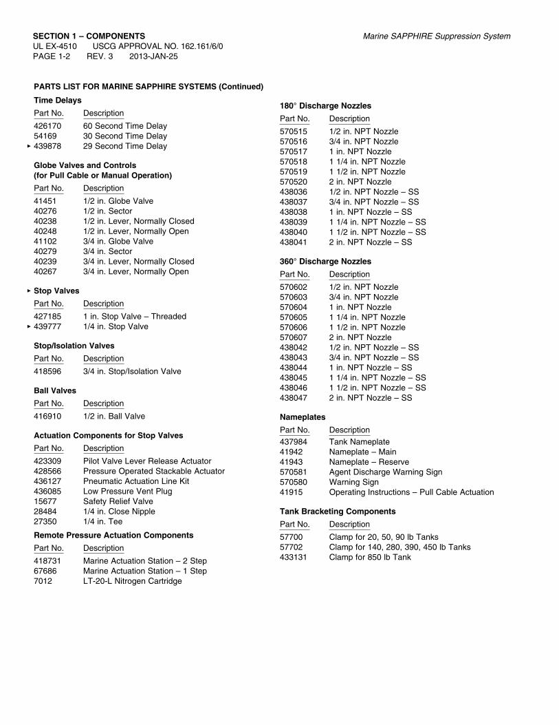
ParTS LIST fOr MarINE SaPPHIrE SySTEMS (Continued)
Time Delays
Part No. Description
426170 60 Second Time Delay54169 30 Second Time Delay439878 29 Second Time Delay
Globe Valves and Controls (for Pull Cable or Manual Operation)
Part No. Description
41451 1/2 in. Globe Valve40276 1/2 in. Sector40238 1/2 in. Lever, Normally Closed40248 1/2 in. Lever, Normally Open41102 3/4 in. Globe Valve40279 3/4 in. Sector40239 3/4 in. Lever, Normally Closed40267 3/4 in. Lever, Normally Open
Stop Valves
Part No. Description
427185 1 in. Stop Valve – Threaded439777 1/4 in. Stop Valve
Stop/Isolation Valves
Part No. Description
418596 3/4 in. Stop/Isolation Valve
Ball Valves
Part No. Description
416910 1/2 in. Ball Valve
actuation Components for Stop Valves
Part No. Description
423309 Pilot Valve Lever Release Actuator428566 Pressure Operated Stackable Actuator436127 Pneumatic Actuation Line Kit436085 Low Pressure Vent Plug15677 Safety Relief Valve28484 1/4 in. Close Nipple27350 1/4 in. Tee
remote Pressure actuation Components
Part No. Description
418731 Marine Actuation Station – 2 Step67686 Marine Actuation Station – 1 Step7012 LT-20-L Nitrogen Cartridge
180° Discharge Nozzles
Part No. Description
570515 1/2 in. NPT Nozzle570516 3/4 in. NPT Nozzle570517 1 in. NPT Nozzle570518 1 1/4 in. NPT Nozzle570519 1 1/2 in. NPT Nozzle570520 2 in. NPT Nozzle438036 1/2 in. NPT Nozzle – SS438037 3/4 in. NPT Nozzle – SS438038 1 in. NPT Nozzle – SS438039 1 1/4 in. NPT Nozzle – SS438040 1 1/2 in. NPT Nozzle – SS438041 2 in. NPT Nozzle – SS
360° Discharge Nozzles
Part No. Description
570602 1/2 in. NPT Nozzle570603 3/4 in. NPT Nozzle570604 1 in. NPT Nozzle570605 1 1/4 in. NPT Nozzle570606 1 1/2 in. NPT Nozzle570607 2 in. NPT Nozzle438042 1/2 in. NPT Nozzle – SS438043 3/4 in. NPT Nozzle – SS438044 1 in. NPT Nozzle – SS438045 1 1/4 in. NPT Nozzle – SS438046 1 1/2 in. NPT Nozzle – SS438047 2 in. NPT Nozzle – SS
Nameplates
Part No. Description437984 Tank Nameplate41942 Nameplate – Main41943 Nameplate – Reserve570581 Agent Discharge Warning Sign570580 Warning Sign41915 Operating Instructions – Pull Cable Actuation
Tank Bracketing Components
Part No. Description
57700 Clamp for 20, 50, 90 lb Tanks57702 Clamp for 140, 280, 390, 450 lb Tanks433131 Clamp for 850 lb Tank

ParTS LIST fOr MarINE SaPPHIrE SySTEMS (Continued)
Miscellaneous System Components
Part No. Description
437900 Pressure Switch – 3PDT43241 Pressure Switch DPST-EXP-Proof5156 Pressure Trip423923 Pressure Test Assembly – CV-98 Valve437616 Pressure-Operated Siren570539 1 in. Flexible Discharge Hose570538 2 in. Flexible Discharge Hose570557 1 in. Single Tank Swivel Adaptor570558 2 in. Single Tank Swivel Adaptor69990 3 in. Discharge Hose69470 3 in. Flared NPT Swivel Adaptor570363 3 in. Flared BSPT Swivel Adaptor570566 1 in. Manifold Check Valve570568 2 in. Manifold Check Valve69841 3 in. Discharge Hose/Check Valve Assembly433290 Novec 1230 Fluid – 1 Gal (3.8 L) Assembly570534 Novec 1230 Fluid – 220 Gal (832.8 L)
Tote Assembly570277 Liquid Level Measuring Device – 280 lb Tank570278 Liquid Level Measuring Device – 390, 850 lb Tanks570589 Liquid Level Measuring Device – 450 lb Tank570585 Low Pressure Switch426460 Microswitch418378 1/2 in. Manifold Safety Relief Rupture Disc
Assembly40309 Header Vent Plug426028 Bleed Down Device79638 Pilot Cylinder Bracket Back Frame73091 Pilot Cylinder Clamp418502 Pilot Cylinder Bracket Bolt with Nut and
Lockwasher427704 Single Cylinder Strap427705 Single Cylinder Channel439871 42 ft3 Nitrogen Pilot Cylinder Bracket Assembly
recharge/rebuild Components
Part No. Description
570574 Spanner Wrench570576 1 in. Recharge Adaptor570592 2 in. Recharge Adaptor69891 3 in. Recharge Adaptor570559 1 in. Rebuild Kit570584 2 in. Rebuild Kit570373 3 in. Rebuild Kit
Marine SAPPHIRE Suppression System SECTION 1 – COMPONENTSUL EX-4510 USCG APPROVAL NO. 162.161/6/0
2013-JAN-25 REV. 0 PAGE 1-2.1
PAGE INTENTIONALLY LEFT BLANK
SECTION 1 – COMPONENTSUL EX-4510 USCG APPROVAL NO. 162.161/6/0 PAGE 1-2.2 REV. 0 2013-JAN-25
Marine SAPPHIRE Suppression System

Marine SAPPHIRE Suppression System SECTION 1 – COMPONENTSUL EX-4510 USCG APPROVAL NO. 162.161/6/0
2013-JAN-25 REV. 2 PAGE 1-3
3M™ NOVEC™ 1230 fIrE PrOTECTION fLuID
Novec 1230 fluid has been developed as a halon replacement alternative to HFCs, HCFCs, and PFCs in special hazard, high value applications. It has unique qualities that provide the right balance of fire extinguishing performance, end use safety, and environmental sustainability. Novec 1230 fluid is low in toxicity and environment impact. It is a liquid at room temperature, with a low vapor pressure, which allows for ease in handling, stor-age, and shipping.
Novec 1230 fluid is available in two sizes of containers:
Part No. 433290 – 1 Gallon (3.8 L) Jug Shipping Assembly
Part No. 570534 – 220 Gallon (832.8 L) Tote Shipping Assembly

SECTION 1 – COMPONENTSUL EX-4510 USCG APPROVAL NO. 162.161/6/0 PAGE 1-4 REV. 2 2013-JAN-25
Marine SAPPHIRE Suppression System
aGENT TaNK SHIPPING aSSEMBLy
The agent tank assemblies consist of a tank fitted with a valve and internal siphon tube. Eight partial filled tank sizes are avail-able. A nameplate is adhered to the tank displaying the agent weight and gross weight. Tanks are superpressurized with dry nitrogen to 360 psi (24.8 bar) at 70 °F (21 °C). All tanks are available in multiple fill increments.
Note: Quantity of agent will have to be specified on customer P.O. when ordering factory filled tank shipping assemblies.
Also, when low pressure switch and liquid level indicator installed options are required, they must be specified when ordering.
TECHNICaL INfOrMaTION
Manufactured in accordance with DOT4BW450 or DOT4BW500 (343L tank manufactured in accordance with DOT4BW450 only).
ULC shipping assemblies are manufactured in accordance with TC4BWM31 (minimum).
Tank markedservice pressure: DOT4BW450 DOT4BW500
Hydraulic test pressure: 900 (62.1 bar) 1000 (69.0 bar)
Working Pressure: 450 (31.0 bar) 500 (34.5 bar)
Paint Specification: Red epoxy polyester or red polyester powder coated
Technical Information 1 in. and 2 in. 3 in.Material: Brass CZ 121 Brass UNS36000
Body Proof Pressure: 2175 psi (150 bar) 2000 psi (138 bar)
Outlet: 1 in. BSPP, 3.0 in. Flare 2 in. BSPP
Low Pressure Port: 1/8 in. NPT 1/8 NPT
Gauge Port: 1/8 in. NPT 1/8 NPT
Pilot Pressure Port: 1/4 in. BSPP 1/4 NPT
Shipping Nominal Approximate Dimension Assembly Tank Size Agent Quantity Empty Weight “A” Diameter ValvePart No. lb (kg) lb (kg) lb (kg) in. (mm) in. (mm) Size570635 9-21 (4.1-9.5) 10-21 (4.5-9.5) 33 (15.0) 12.0 (305) 10 (254) 1 in.570633 18-42 (8.2-19.1) 20-46 (9.1-21.0) 41 (18.6) 19.8 (503) 10 (254) 1 in.570634 36-84 (16.3-38.1) 37-88 (16.8-40.0) 58 (26.3) 32.8 (833) 10 (254) 1 in.570638 58-137 (26.3-62.1) 58-138 (26.3-62.6) 108 (49.0) 23.5 (597) 16 (406) 2 in.570639* 117-280 (53.1-127.0) 116-280 (52.6-127.0) 158 (71.7) 40.2 (1021) 16 (406) 2 in.570640* 163-388 (73.9-176.0) 161-388 (73.0-176.0) 198 (89.8) 53.3 (1354) 16 (406) 2 in.570641* 199-459 (90.3-208.2) 194-459 (88.0-208.2) 233 (105.7) 64.3 (1633) 16 (406) 2 in.570586* 379-851 (172-386.0) 375-851 (170.1-386.0) 456 (206.8) 57.7 (1466) 24 (610) 3 in.
*Note 1: 106, 147, 180, and 343 liter tanks contain provisions for liquid level indicators. Note 2: A low pressure switch is available for all cylinder/valve assemblies. Note 3: The liquid level indicator and low pressure switch must be ordered at the time the tank is ordered.
A
004838
GAUGE
OUTLET ADAPTOR
LOW PRESSURE PORT
PILOT PRESSURE PORT (BACK SIDE)

TaNK NaMEPLaTE (ParT NO. 437984)
The tank label details the weight of Novec 1230 contained, fill location, hazard information and inspection procedures for the SAPPHIRE® Marine suppression system. Once the label is applied to the tank surface, and to avoid possible tampering, it cannot be removed intact.
SPECIfICaTIONS
Material . . . . . . . . . . . . . . . . . . . . . . . . .Aluminum
Dimensions . . . . . . . . . . . . . . . . . . . . . 15.0 in x 6.5 in. (381 mm x 165 mm)
Marine SAPPHIRE Suppression System SECTION 1 – COMPONENTSUL EX-4510 USCG APPROVAL NO. 162.161/6/0
2013-JAN-25 REV. 1 PAGE 1-4.1

PAGE INTENTIONALLY LEFT BLANK
SECTION 1 – COMPONENTSUL EX-4510 USCG APPROVAL NO. 162.161/6/0 PAGE 1-4.2 REV. 1 2013-JAN-25
Marine SAPPHIRE Suppression System
Marine SAPPHIRE Suppression System SECTION 1 – COMPONENTSUL EX-4510 USCG APPROVAL NO. 162.161/6/0
2013-JAN-25 REV. 3 PAGE 1-5
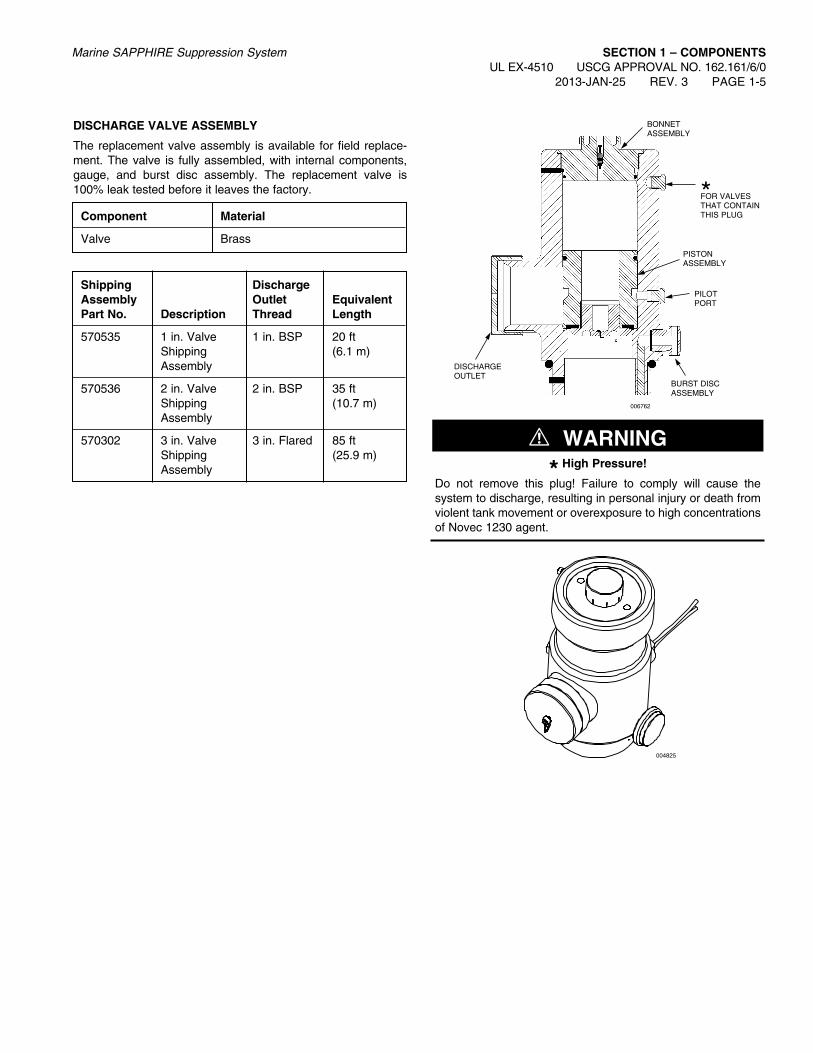
DISCHarGE VaLVE aSSEMBLy
The replacement valve assembly is available for field replace-ment. The valve is fully assembled, with internal components, gauge, and burst disc assembly. The replacement valve is 100% leak tested before it leaves the factory.
! WarNING
* High Pressure!
Do not remove this plug! Failure to comply will cause the system to discharge, resulting in personal injury or death from violent tank movement or overexposure to high concentrations of Novec 1230 agent.
004825
Component Material
Valve Brass
Shipping Discharge assembly Outlet Equivalent Part No. Description Thread Length
570535 1 in. Valve 1 in. BSP 20 ft Shipping (6.1 m) Assembly
570536 2 in. Valve 2 in. BSP 35 ft Shipping (10.7 m) Assembly
570302 3 in. Valve 3 in. Flared 85 ft Shipping (25.9 m) Assembly
006762
BURST DISC ASSEMBLY
PISTONASSEMBLY
*FOR VALVES THAT CONTAIN THIS PLUG
PILOTPORT
DISCHARGEOUTLET
BONNETASSEMBLY

SECTION 1 – COMPONENTSUL EX-4510 USCG APPROVAL NO. 162.161/6/0 PAGE 1-6 REV. 2 2013-JAN-25
Marine SAPPHIRE Suppression System
aGENT TaNK BraCKETS
Each tank must be secured with two brackets. Each bracket assembly includes two bracket halves with fastening nut, bolt, and washer. Brackets are designed to be used in conjunction with continuous slot channel.
Bracket assemblies are manufactured from 304 stainless steel with S.S. nut, bolt, and washer.
Nominal BracketTank Bracket Tank Dimension ApproximateSize Part Diameter A and B Weight(lb) No. in. (mm) in. (mm) lb (kg)
20, 50, 90 57700 10 (254) 10.4 (264) 2 (0.9)
140, 280, 57702 16 (406) 16.1 (409) 3 (1.4) 390, 450
850 433131 24 (610) 24.5 (622) 4 (1.8)
Back channel is not supplied with the bracket and must be ordered separately. Refer to Components Section, Page 1-7, for description of acceptable channel.
006966
1 1/2 IN.(38 mm)
2 IN.(51 mm)
1 3/8 IN.(35 mm)
0.508 IN.(13 mm)
0.38 IN.(10 mm)
B
A
0.1345 IN.(3 mm)

Marine SAPPHIRE Suppression System SECTION 1 – COMPONENTSUL EX-4510 USCG APPROVAL NO. 162.161/6/0
2013-JAN-25 REV. 3 PAGE 1-7
BraCKET CHaNNEL
Bracket channel shall be of the modular type, formed from 12 gauge, 0.105 in. (3 mm) steel. The channel shall be painted, or otherwise protected from corrosion. Approved channel sizes and manufacturers are listed below. Channel is to be ordered direct from manufacturer or manufacturer’s dealers.
006967
3 1/4 IN.(83 mm)
2 7/16 IN.(62 mm)
1 5/8 IN.(41 mm)
3/8 IN.(9.5 mm)
3/8 IN.(9.5 mm)
1 5/8 IN.(41 mm)
7/8 IN.(22 mm)
9/32 IN.(7.1 mm)
0.105 IN.(2.7 mm)
GLOBESTRUT – G-5812POWERSTRUT – PS-200UNISTRUT – P1000
GLOBESTRUT – G-7612POWERSTRUT – PS-150UNISTRUT – P5500
GLOBESTRUT – 2512POWERSTRUT – PS-100UNISTRUT – P5000

fLEXIBLE DISCHarGE HOSE
The flexible discharge hose is used to connect the tank valve outlet to rigid distribution piping. On single tank systems, a check valve is not required. Three sizes of flexible discharge hoses are available: 1 in. (for 20, 50, and 90 lb tank sizes), 2 in. (for 140, 280, 390, and 450 lb tank sizes), and 3 in. (for 850 lb tank sizes).
For 1 in. flexible hose, adaptor (Part No. 570557) is required to connect the valve outlet to rigid pipe.
For 2 in. flexible hose, adaptor (Part No. 570558) is required to connect the valve outlet to rigid pipe.
SECTION 1 – COMPONENTSUL EX-4510 USCG APPROVAL NO. 162.161/6/0 PAGE 1-8 REV. 2 2013-JAN-25
Marine SAPPHIRE Suppression System
Component Material
1 and 2 in. Flexible Oil-resistant seamless Discharge Hose synthetic rubber
Shipping assembly Equivalent Part No. Description Length
570539 1 in. Flexible 10.3 ft Discharge Hose (3.1 m)
570538 2 in. Flexible 17.6 ft Discharge Hose (5.4 m)
570557 1 in. Single Tank 0.6 ft Swivel Adaptor (0.2 m)
570558 2 in. Single Tank 1.2 ft Swivel Adaptor (0.4 m)
006760
aDaPTOr – TaNK TO PIPE
1 IN. aDaPTOr2 1/2 IN. (64 mm)
2 IN. aDaPTOr3 3/16 IN. (81 mm)
NPT FEMALE
BSPTFEMALE
006760
1 aND 2 IN. fLEXIBLE DISCHarGE HOSE
1 IN. HOSE3 IN. (79 mm)
2 IN. HOSE5 IN. (127 mm)
1 IN. HOSE16 IN.
(406 mm)
2 IN. HOSE20 3/8 IN.(517 mm)
NPT
BSPT

Marine SAPPHIRE Suppression System SECTION 1 – COMPONENTSUL EX-4510 USCG APPROVAL NO. 162.161/6/0
2013-JAN-25 REV. 2 PAGE 1-8.1
3 IN. DISCHarGE HOSE/CHECK VaLVE aSSEMBLy
The 3 in. discharge hose/check valve assembly combines the elbow, hose, check valve, and swivel coupling for connection to the valve discharge outlet and the discharge manifold in a mul-tiple tank system. The check valve provides a 1 1/2 in. (38 mm) height adjustment. This assembly is spring loaded and therefore not required to always be oriented vertically.
Component Material
3 in. Discharge Hose: Double Braided Stainless SteelHose/Check Elbow: Stainless Steel UNS 30400Valve Valve Swivel Nut: Stainless Steel UNS 30400 Check Valve Body: Cadmium Plated Mild Steel Check Valve Seal and Seat: Brass UNS 36000 Spring: Stainless Steel
3 IN. DISCHarGE HOSE
The discharge hose (Part No. 69990) is used with the 3 in. NPT adaptor and 90° elbow to connect the tank valve outlet to the dis-tribution piping in single tank systems. The hose is constructed of corrugated stainless steel tubing with stainless braid cover. The minimum bending radius for the 3 in. hose is 18 in. (457 mm).
3 IN. VaLVE SINGLE TaNK aDaPTOrS
When a single 379 lb (172.0 kg) tank module is being used with-out a manifold, two swivel adaptors are available for connection to the discharge outlet and either NPT or BSPT.
ShippingAssembly EquivalentPart No. Description Length
69841 3 in. Discharge Hose/ 52.0 ft (15.8 m) Check Valve Assembly
69990 3 in. Discharge Hose 5.1 ft (1.6 m)
69470 3.5 in. Flared to 3 in. NPT 1.8 ft (0.5 m) Single Tank Swivel Adaptor
570363 3.5 in. Flared to 3 in. BSPT 1.8 ft (0.5 m) Single Tank Swivel Adaptor
006249
3 IN. NPT
ParT NO. 69990
16 IN.(406 mm)
006248
3.5 IN. FLARED SWIVEL FOR TANK VALVE
3 IN. NPT OR 3 IN. BSPT
4.5 IN.(114 mm)
3 IN. FLARED SWIVEL
3 IN. NPT
CHECK VALVE
006247
8 1/2 IN.(216 mm)
APPROX.27 1/2 IN.(699 mm)

PAGE INTENTIONALLY LEFT BLANK
SECTION 1 – COMPONENTSUL EX-4510 USCG APPROVAL NO. 162.161/6/0 PAGE 1-8.2 REV. 1 2013-JAN-25
Marine SAPPHIRE Suppression System

Marine SAPPHIRE Suppression System SECTION 1 – COMPONENTSUL EX-4510 USCG APPROVAL NO. 162.161/6/0
2013-JAN-25 REV. 3 PAGE 1-9
MaNIfOLD CHECK VaLVES
The manifold check valve is designed to prevent a loss of agent during a discharge in the event that a tank has been removed from the system. The check valve is a “mushroom” type, which lifts into the manifold as discharge occurs.
Two sizes of manifold check valves are available: 1 in. and 2 in.
Manifolds are constructed of standard Schedule 40 pipe and 300 lb fittings. The check valves assemble directly into the fittings. When installing, the check valves must be oriented vertically.
ThreadComponent Material Type
Check Body: Brass 1 in. NPTValve Stem and Seal: and
Stainless Steel 2 in. NPT
ShippingAssembly EquivalentPart No. Description Length570566 1 in. Manifold Check Valve 1.3 ft (0.4 m)570568 2 in. Manifold Check Valve 21.8 ft (6.6 m)
1.5 IN. (FOR 1 IN. MANIFOLD CHECK VALVE) OR 2.5 IN. (FOR 2 IN. MANIFOLD CHECK VALVE) NPT MALE FOR MANIFOLD INLET CONNECTION
1 IN. OR 2 IN. NPT FEMALE FOR DISCHARGE HOSE CONNECTION
006889

SECTION 1 – COMPONENTSUL EX-4510 USCG APPROVAL NO. 162.161/6/0 PAGE 1-10 REV. 2 2013-JAN-25
Marine SAPPHIRE Suppression System
PAGE INTENTIONALLY LEFT BLANK

Marine SAPPHIRE Suppression System SECTION 1 – COMPONENTSUL EX-4510 USCG APPROVAL NO. 162.161/6/0
2013-JAN-25 REV. 2 PAGE 1-11
DISCHarGE NOZZLES
The discharge nozzles are available in a 180° and 360° pattern and are designed to uniformly distribute the Novec™ 1230 agent throughout the hazard area.
The 180° nozzle has seven ports and the 360° nozzle has six-teen ports. Six sizes of nozzles are available, 1/2 through 2 in.
The hydraulic flow program will determine the nozzle size and orifice size required.
Note: When ordering nozzles, orifice size must be specified.
Nozzles are supplied as standard in Brass. Stainless Steel is available as a special order option. Contact Marine Technical Services for ordering details.
Shipping assembly Part No.
Brass Stainless Steel Description
570515 438036 1/2 in. NPT Nozzle – 180°
570516 438037 3/4 in. NPT Nozzle – 180°
570517 438038 1 in. NPT Nozzle – 180°
570518 438039 1 1/4 in. NPT Nozzle – 180°
570519 438040 1 1/2 in. NPT Nozzle – 180°
570520 438041 2 in. NPT Nozzle – 180°
570602 438042 1/2 in. NPT Nozzle – 360°
570603 438043 3/4 in. NPT Nozzle – 360°
570604 438044 1 in. NPT Nozzle – 360°
570605 438045 1 1/4 in. NPT Nozzle – 360°
570606 438046 1 1/2 in. NPT Nozzle – 360°
570607 438047 2 in. NPT Nozzle – 360°
004824
004823
004840
180° NOZZLEPATTERN
360° NOZZLEPATTERN

SECTION 1 – COMPONENTSUL EX-4510 USCG APPROVAL NO. 162.161/6/0 PAGE 1-12 REV. 3 2013-JAN-25
Marine SAPPHIRE Suppression System
PNEuMaTIC aCTuaTOr
The pneumatic actuator is required to pneumatically actuate the agent tanks. The actuator operates from pressure received from the pilot cylinders via a flexible hose. When the pneumatic actu-ator is pressurized, the internal actuator piston pushes down on the valve stem, opening the tank valve, allowing the agent to discharge.
TECHNICaL INfOrMaTION
Body: Brass CZ121Actuation Pin: Stainless SteelPiston Rod: Brass CZ 121Pipe Connection: 1/4 in. NPT FemaleMin. Actuation Pressure: 4 bar (58 psi)Max. Working Pressure: 56 bar (812 psi)Overall Size: 1.89 in. (L) x 1.63 in. (Dia) (48 mm (L) x 41 mm (Dia))Weight: 0.228 kg (0.503 lb)
Part No. Description
570550 Pneumatic Actuator
1/4 IN. NPT
006764

Marine SAPPHIRE Suppression System SECTION 1 – COMPONENTSUL EX-4510 USCG APPROVAL NO. 162.161/6/0
2013-JAN-25 REV. 1 PAGE 1-12.1
MaNuaL aCTuaTOr
The local manual actuator is used to mechanically operate the tank. To prevent accidental actuation, the actuator contains a steel safety pin. The pin must be removed to operate the actu-ator. The actuator is operated by depressing the strike button.
The actuator can be mounted either on the top port of the tank valve or on top of the electric solenoid valve.
TECHNICaL INfOrMaTION
Body: Brass CZ 121Knob: PVC (Colour: Red)Safety Pin: Stainless Steel 303Piston Rod: Brass CZ 121Min. Actuation Force: 25.5 N (5.73 lbf)Overall Size: 2.05 in. (L) x 1.63 in. (Dia) ( 52 mm (L) x 41 mm (Dia))Weight: 0.265 kg (0.584 lb)
Part No. Description570549 Manual Actuator
006890
STRIKEBUTTON
SAFETYPIN
PAGE INTENTIONALLY LEFT BLANK
SECTION 1 – COMPONENTSUL EX-4510 USCG APPROVAL NO. 162.161/6/0 PAGE 1-12.2 REV. 1 2013-JAN-25
Marine SAPPHIRE Suppression System
Marine SAPPHIRE Suppression System SECTION 1 – COMPONENTSUL EX-4510 USCG APPROVAL NO. 162.161/6/0
2013-JAN-25 REV. 2 PAGE 1-13
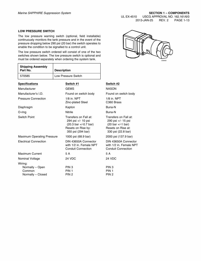
LOW PrESSurE SWITCH
The low pressure warning switch (optional, field installable) continuously monitors the tank pressure and in the event of the pressure dropping below 290 psi (20 bar) the switch operates to enable the condition to be signalled to a control unit.
The low pressure switch ordered will consist of one of the two switches shown below. The low pressure switch is optional and must be ordered separately when ordering the system tank.
Shipping assembly Part No. Description
570585 Low Pressure Switch
008469
Specifications Switch #1 Switch #2
Manufacturer GEMS NASON
Manufacturer’s I.D. Found on switch body Found on switch body
Pressure Connection 1/8 in. NPT 1/8 in. NPT Zinc-plated Steel C360 Brass
Diaphragm Kapton Buna-N
O-ring Nitrile Buna-N
Switch Point Transfers on Fall at: Transfers on Fall at: 294 psi +/- 10 psi 290 psi +/- 15 psi (20.3 bar +/-0.7 bar) (20 bar +/-1 bar) Resets on Rise by: Resets on Rise at: 350 psi (294 bar) 330 psi (22.8 bar)
Maximum Operating Pressure 1000 psi (68.9 bar) 2000 psi (137.9 bar)
Electrical Connection DIN 43650A Connector DIN 43650A Connector with 1/2 in. Female NPT with 1/2 in. Female NPT Conduit Connection Conduit Connection
Maximum Current 5 A 5 A
Nominal Voltage 24 VDC 24 VDC
Wiring: Normally – Open PIN 3 PIN 3 Common PIN 1 PIN 1 Normally – Closed PIN 2 PIN 2

SECTION 1 – COMPONENTSUL EX-4510 USCG APPROVAL NO. 162.161/6/0 PAGE 1-13.1 REV. 1 2013-JAN-25
Marine SAPPHIRE Suppression System
CPM aCTuaTOr
The Cable Pneumatic Manual (CPM) Actuator (Part No. 436796) may be used to operate the system from a remote position using a manual release unit which is connected to the CPM Actuator by wire rope run in conduit. Local manual actuation is also possible using this actuator. In addition, pneumatic operation is available via the actuation port in the body of the actuator.
The CPM Actuator is designed so that it may be fitted to the top of the valve assembly or used in conjunction with a removable electrical actuator.
CPM Actuator – Part No. 436796
008633
008539
CPM Actuator – Manually Actuated Position
008634
CPM Actuator – Cable Actuated Position
Inadvertent manual operation is prevented by a “safety pin.” Normal manual operation requires that the safety pin be pulled from the handle to allow the lever to be moved to the actuated “up” position. With the safety pin inserted, cable actuation is not inhibited.
Both manual and cable operation can be disabled by a “disable key.” The disable key must be removed to put the actuator in service for manual cable operation.
SPECIfICaTIONS
Body: Brass C36000
Lever Arm: Brass C36000
Safety Pin: Stainless Steel
Actuation Pin: Stainless Steel
Swivel Nut: Brass C36000
Swivel Nut Connection: 1 in. BSPP
Pneumatic Input Port: 1/8 in. NPT Female
Min. Actuation Pressure: 6.9 bar (100 psi)
Max. Working Pressure: 1750 psi (121 bar)
Overall Size: W: 3.1 in. (79 mm) L: 7.1 in. (180 mm) H: 5.4 in. (140 mm)
Weight: 2.65 lb (1.20 kg)
008633
PNEUMATIC INPUT PORT

PAGE INTENTIONALLY LEFT BLANK
Marine SAPPHIRE Suppression System SECTION 1 – COMPONENTSUL EX-4510 USCG APPROVAL NO. 162.161/6/0
2013-JAN-25 REV. 1 PAGE 1-13.2

SECTION 1 – COMPONENTSUL EX-4510 USCG APPROVAL NO. 162.161/6/0 PAGE 1-14 REV. 2 2013-JAN-25
Marine SAPPHIRE Suppression System
PRESSUREGAUGE
SAFETYRELIEFVALVE
002252
3 1/2 IN.(89 mm)
REFERENCEVALVE
HEIGHT TO OUTLETCENTER
002251
RECORDTAG
PRESSUREGAUGE
CYLINDERSHIPPING CAP
VALVE SHIPPING CAP
11 IN.(279 mm)
67 IN.(1702 mm)
NITrOGEN PILOT CyLINDEr
The Nitrogen Pilot Cylinder is factory filled with nitrogen. The quantity of pilot cylinders required is based on the number of agent tanks in the system.
The cylinders can be actuated pneumatically, manually, or by remote cable pull.
Component Material
Cylinder SteelValve BrassSafety Relief Valve BrassShipping Cap Steel
ShippingAssemblyPart No. Description
433098 Nitrogen Pilot Cylinder DOT 3AA2100 and either TC3AM176 or TC3AA176
Note: The CV-98 valve is not field-serviceable.

VALVE
HEIGHT TO OUTLETCENTER
009062
RECORDTAG PRESSURE
GAUGE
CYLINDERSHIPPING CAP
VALVE SHIPPING CAP
7 IN.(178 mm)
19.7 IN.(500 mm)
Marine SAPPHIRE Suppression System SECTION 1 – COMPONENTSUL EX-4510 USCG APPROVAL NO. 162.161/6/0
2013-JAN-25 REV. 0 PAGE 1-14.1
PRESSUREGAUGE
SAFETYRELIEFVALVE
002252
3 1/2 IN.(89 mm)
REFERENCE
42 fT³ NITrOGEN PILOT CyLINDEr
Note: Only to be installed in systems utilizing a 42 ft3 nitrogen pilot cylinder. System requirements found in Section 13 – appendix 2.
The 42 ft³ Nitrogen Pilot Cylinder is factory filled with nitrogen. A single 42 ft³ nitrogen pilot cylinder can be installed in a system containing one or two agent tanks under the installation limita-tions and requirements specified in Appendix 2.
The cylinder can be actuated pneumatically, manually, or by remote cable pull.
Component Material
Cylinder SteelValve BrassSafety Relief Valve BrassShipping Cap Steel
Shipping ApproximateAssembly WeightPart No. Description lb (kg)
439783 42 ft³ Nitrogen Pilot Cylinder 37.8 (17.1) DOT 3AA2175 and TC3AA166
Note: The CV-98 valve is not field-serviceable.

PAGE INTENTIONALLY LEFT BLANK
SECTION 1 – COMPONENTSUL EX-4510 USCG APPROVAL NO. 162.161/6/0 PAGE 1-14.2 REV. 0 2013-JAN-25
Marine SAPPHIRE Suppression System

Marine SAPPHIRE Suppression System SECTION 1 – COMPONENTSUL EX-4510 USCG APPROVAL NO. 162.161/6/0
2013-JAN-25 REV. 2 PAGE 1-15
NITrOGEN PILOT CyLINDEr BraCKET
Material: Steel
Part No. Description
79638 Back Frame – 2 required73091 Cylinder Clamp – 2 required418502 Carriage Bolt with Lockwasher and Nut – 2 required427704 Single Cylinder Strap (Steel) – 2 required427705 Single Cylinder Channel (Steel) – 2 required
finish:Back Frame – Red Polyester Powder PaintCylinder Clamp – Red Polyester Powder PaintCarriage Bolt/Washer and Nut – Zinc Plated
006963b
52 IN.(1321 mm)
14 IN.(356 mm)
006963a
13 1/2 IN.(343 mm)
12 IN.(305 mm)
5 IN.(127 mm)
BACK FRAME
CYLINDERCLAMP
CARRIAGEBOLT
008688
SINGLECYLINDER STRAP
SINGLE CYLINDER CHANNEL
18 3/8 IN.(467 mm)

SECTION 1 – COMPONENTSUL EX-4510 USCG APPROVAL NO. 162.161/6/0 PAGE 1-15.1 REV. 1 2013-JAN-25
Marine SAPPHIRE Suppression System
42 fT³ NITrOGEN PILOT CyLINDEr BraCKET aSSEMBLy
Note: Only to be installed in systems utilizing a 42 ft3 nitrogen pilot cylinder. System requirements found in Section 13 – appendix 2.
Each cylinder must be secured with two bracket straps. Each bracket assembly includes four bracket halves with fastening nuts, bolts, and washers. Brackets are designed to be used in conjunction with continuous slot channel.
Bracket assemblies are manufactured from 304 stainless steel with S.S. nuts, bolts, and washers.
Shipping ApproximateAssembly WeightPart No. lb (kg)
439781 2.8 (1.3)
Back channel is not supplied with the bracket and must be ordered separately. Refer to Components Section, Page 1-7, for description of acceptable channel.
009063
9.50 IN.(241 mm)
10.0 IN.(254 mm)
10.2 IN.(259 mm)
3.00 IN.(76 mm)
P1000 UNISTRUT CHANNEL OR EQUAL
1.50 IN.(38 mm)
0.135 IN.(3 mm)
1.38 IN.(35 mm)
7.12 IN.(181 mm)
7.12 IN.(181 mm)
0.38 IN.(10 mm)
0.73 IN.(19 mm)
2.0 IN.(51 mm)
CYLINDER FOUNDATION BY OTHERS

LIQuID LEVEL INDICaTOr
The liquid level indicator is used to measure the level of liquid Novec™ 1230 agent in the tanks. The amount (weight) of agent is determined by converting the level measurement into a weight measurement using the weight conversion tables located in this manual.
The liquid level is found by lifting the measuring tape from inside the tube to the end (or approximately 3 in. (76 mm) above the anticipated liquid level) and slowly lowering the tape until a mag-netic interlock with the float is felt. The tape will then remain in the up position, allowing a reading at the top of the housing. This measurement is accomplished without removing the tank from the fire suppression system.
The indicator can be installed in empty tanks with the proper port or tanks can be ordered with the indicator already installed.
Component MaterialLiquid Level Body: BrassIndicator Tape: Steel
Shipping AssemblyPart No. Description
570277 Liquid Level Indicator for 280 lb Tank570278 Liquid Level Indicator for 390 and 850 lb Tanks570589 Liquid Level Indicator for 450 lb Tank
Marine SAPPHIRE Suppression System SECTION 1 – COMPONENTSUL EX-4510 USCG APPROVAL NO. 162.161/6/0
2013-JAN-25 REV. 1 PAGE 1-15.2
006255

SECTION 1 – COMPONENTSUL EX-4510 USCG APPROVAL NO. 162.161/6/0 PAGE 1-16 REV. 3 2013-JAN-25
Marine SAPPHIRE Suppression System
PILOT VaLVE LEVEr rELEaSE aCTuaTOr
The manual lever release actuator provides a manual means of actuating pilot cylinder valves and stop valves. This can be accomplished by direct manual actuation of its pull lever or cable actuation when used in conjunction with a remote manual pull station. When used with a remote manual pull station, the pull station must contain the components necessary to meet the actuator lever traveling requirements of 7 in. (178 mm).
The actuator is shipped with ring pin and chain attached. If the ring pin is not required, it must be removed. Failure to remove the ring pin/chain assembly will prevent system actuation if a remote cable pull actuation system is employed and the ring pin is accidentally installed in the actuator.
Component MaterialAll Manual Cable-pull Brass withActuator Stainless Steel Pin
ShippingAssemblyPart No. Description
423309 Lever Release (1 1/8-18 mounting thread) – Mounts directly to a CV-98 pilot cylinder valve.
3 7/8 IN.(98 mm)
DEPTH: 3 7/8 IN. (98 mm)
3 7/8 IN.*(98 mm)
000897
*Add 1 9/16 in. (40 mm) to height when lever is in the straight up position.
PIN
Marine SAPPHIRE Suppression System SECTION 1 – COMPONENTSUL EX-4510 USCG APPROVAL NO. 162.161/6/0
2013-JAN-25 REV. 2 PAGE 1-17
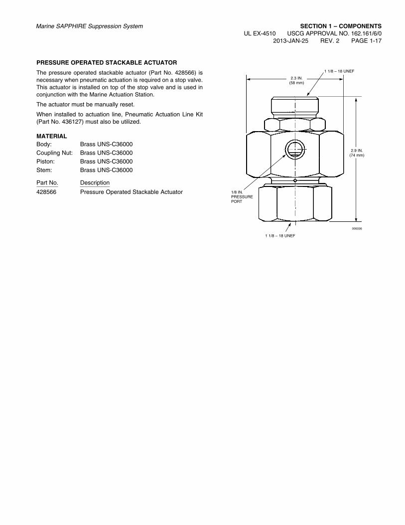
PrESSurE OPEraTED STaCKaBLE aCTuaTOr
The pressure operated stackable actuator (Part No. 428566) is necessary when pneumatic actuation is required on a stop valve. This actuator is installed on top of the stop valve and is used in conjunction with the Marine Actuation Station.
The actuator must be manually reset.
When installed to actuation line, Pneumatic Actuation Line Kit (Part No. 436127) must also be utilized.
MaTErIaLBody: Brass UNS-C36000Coupling Nut: Brass UNS-C36000Piston: Brass UNS-C36000Stem: Brass UNS-C36000
Part No. Description
428566 Pressure Operated Stackable Actuator
006036
2.3 IN.(58 mm)
1/8 IN.PRESSUREPORT
1 1/8 – 18 UNEF
1 1/8 – 18 UNEF
2.9 IN.(74 mm)

SECTION 1 – COMPONENTSUL EX-4510 USCG APPROVAL NO. 162.161/6/0 PAGE 1-18 REV. 2 2013-JAN-25
Marine SAPPHIRE Suppression System
CONNECTING LINK
The connecting link is used to connect two lever releases together when two pilot cylinders are required for actuation. The connecting link can be used on lever releases installed on CV-98 valves.
One size connecting link is available for all size cylinders.
Component Material Paint
Connecting Link Steel Red Enamel
Shipping assembly Part No. Description
42514 Connecting link
001885
PIVOT PIN
3/4 IN. (19 mm)
FLEXLOCK HEX NUT
007978
2 5/16 IN. (59 mm)
14 1/4 IN. (362 mm)

Marine SAPPHIRE Suppression System SECTION 1 – COMPONENTSUL EX-4510 USCG APPROVAL NO. 162.161/6/0
2013-JAN-25 REV. 2 PAGE 1-19
MaNuaL PuLL BOX (LaTCHED DOOr TyPE)
The pull box on a SAPPHIRE system is used to provide mechanical release of the system from a manually operated remote station. The latched door type has a solid cast brass door which must be opened to reach the pull handle. A 3/8 in. female NPT opening is provided at the back of the enclosure for connection of the cable housing.
A pulley elbow may be attached directly to the back of the pull box, if necessary, to provide immediate changes in pull cable direction. With this option, the pull box can be extended an additional 3 1/2 in. (89 mm) from the mounting surface by using support legs attached to the back of the pull box. One set of 2 mounting legs is required.
MaTErIaLBody: Brass ASTM B-124 (painted red)Hinged Door: Brass SAE40 (painted red)Handle: Brass ASTM B-124Support Legs: Brass SAE40 (painted red)
ShippingAssemblyPart No. Description
45062 Latch door type pull box41542 Support legs (one set of 2)
FOR FIRE
OPEN DOOR
PULL HANDLE HARD
4 3/16 IN.(106 mm)
000684b
Manual Pull Box Latched Door Type – Part No. 45062
KNOB TOOPEN PULLBOX DOORLEAD AND
WIRE SEAL –BROKENSIMULTANEOUSLYWHEN KNOB ISPULLED
HINGEDDOORMOISTURE-PROOF
JOINT
3/8 IN. NPT
PULLHANDLE
1/16 IN. STAINLESSSTEEL PULL CABLE
STAINLESS STEEL PULL CABLE IS NOT INCLUDED WITH PULL BOX (PART NO. 45062)
3/8 IN. PIPE FOR ENCLOSINGPULL CABLE
BODY
1 7/16 IN.(36 mm)
1 15/16 IN.(49 mm) 000684a
4 1/8 IN.(104 mm)

SECTION 1 – COMPONENTSUL EX-4510 USCG APPROVAL NO. 162.161/6/0 PAGE 1-20 REV. 2 2013-JAN-25
Marine SAPPHIRE Suppression System
MaNuaL PuLL BOX (Continued)
MaNuaL PuLL BOX (BrEaK GLaSS TyPE “a”)
The pull box on a SAPPHIRE system is used to provide mech-anical release of the system from a manually operated remote station. The Break Glass Type “A” Pull Box has a break glass window and a spring mounted handle which rotates forward for use when the glass is broken. A 3/8 in. female NPT opening is provided at the back of the enclosure for connection of the cable housing.
A pulley elbow may be attached directly to the back of the pull box, if necessary, to provide immediate changes in pull cable direction. With this option, the pull box can be extended an additional 3 1/2 in. (89 mm) from the mounting surface by using support legs attached to the back of the pull box (one set for latched door type, two sets for break-glass type).
Each set of mounting support legs contains 2 legs. Two sets are required for the Break Glass Type “A” Pull Box.
MaTErIaLBody: Brass SAE40 (painted red)Hinged Cover: Brass SAE40 (painted red)Handle: Brass ASTM B-124
Part No. Description
41527 Type “A” Break Glass Pull Box41542 Support Legs (one set of 2)
IN CASE OF FIREBREAK GLASS AND
PULL HANDLE HARD UNTIL RED PAINT MARK ON CABLE SHOWS
3 1/4 IN.(82 mm)
4 7/16 IN.(112 mm)
4 7/8 IN.(123 mm)
3 IN.(76 mm)
BRASS HAMMER AND CHAIN SECURED TO BOX
4 – 3/16 IN. MOUNTING HOLES
PROTECTED HAZARD ENGRAVED INNAMEPLATE
000676b
Manual Pull Box Break Glass Type “a” – Part No. 41527
2 3/16 IN.(56 mm)
3/8 IN. PIPE TO ENCLOSE PULL CABLE
CAST BRASS BODY (PAINTED RED)
SPRING FORCES HANDLE OUT INTO OPERATING POSITION WHEN GLASS IS BROKEN
STOWAGE SPACE FOR SPARE BREAK GLASS
CAST BRASS HINGED COVER (PAINTED RED)
GLASS FRONT
PULLHANDLE
MOISTUREPROOF JOINT
1/16 IN. STAINLESS STEEL PULL CABLE
000676a

MaNuaL PuLL BOX (Continued)
TyPICaL PuLL BOX INSTaLLaTION
Marine SAPPHIRE Suppression System SECTION 1 – COMPONENTSUL EX-4510 USCG APPROVAL NO. 162.161/6/0
2013-JAN-25 REV. 1 PAGE 1-20.1
008805
5 11/16 IN.(144 mm)
SHIP’S BULKHEAD
3/8 IN. SHORT NIPPLE
3/8 IN. CLOSE NIPPLE
SUPPORT LEGS
CORNER PULLEY
DIRECTLY ON BULKHEAD
3/8 IN. PIPE
WITH SUPPORT LEGS 3/8 IN. PIPE
TYPE “A”BREAK GLASS PULL BOX
TYPE “A”BREAK GLASS PULL BOX
2 3/16 IN. (56 mm)

PAGE INTENTIONALLY LEFT BLANK
SECTION 1 – COMPONENTSUL EX-4510 USCG APPROVAL NO. 162.161/6/0 PAGE 1-20.2 REV. 1 2013-JAN-25
Marine SAPPHIRE Suppression System

Marine SAPPHIRE Suppression System SECTION 1 – COMPONENTSUL EX-4510 USCG APPROVAL NO. 162.161/6/0
2013-JAN-25 REV. 2 PAGE 1-21
COMBINaTION LaTCH aND BrEaK GLaSS PuLL BOX – ParT NO. 42329
The pull box on a SAPPHIRE system provides mechanical release of the system or directional valve from a manually oper-ated remote station. To operate, release both latches and open the door. Break the glass with the hammer attached to side of box. When the glass is broken, a spring rotates the handle for-ward for a straight pull.
Component Material
Watertight latch- Brass (painted red) type pull box
ShippingAssemblyPart No. Description
42329 Type “B” Latch Type Pull Box (watertight)
3 1/8 IN.(79 mm)
MOISTUREPROOF JOINT
PULLHANDLE
GLASS FRONT
DRAIN HOLE
HINGED COVER
“O” RINGGASKET
HINGED FRONT WITH GLASS
LEVER TYPE LATCH
BRASS HAMMER AND CHAIN SECURED TO BOX
4 – 9/32 IN. DIAMETERMOUNTING HOLES
PROTECTED HAZARD ENGRAVED IN NAMEPLATE
IN CASE OF FIRERELEASE LATCHES,OPEN DOOR, BREAK
GLASS AND PULLHANDLE HARD UNTILRED PAINT MARK ON
CABLE SHOWS
BODY
1/16 IN. STAINLESS STEEL PULL CABLE
STAINLESS STEEL PULL CABLE NOT INCLUDED IN PULL BOX ASSEMBLIES
STOWAGE SPACE FOR SPARE BREAK GLASS
SPRING FORCES HANDLE OUT INTO OPERATING POSITION WHEN GLASS IS BROKEN
3/8 IN. CONDUIT TO ENCLOSE PULL CABLE
2 1/2 IN.(64 mm)
6 3/4 IN.(171 mm)
4 7/8 IN.(124 mm)
3 IN.(76 mm)
000680

SECTION 1 – COMPONENTSUL EX-4510 USCG APPROVAL NO. 162.161/6/0 PAGE 1-22 REV. 2 2013-JAN-25
Marine SAPPHIRE Suppression System
ENCLOSED DOuBLE CaBLE PuLL BOX WITH MICrOSWITCH
The double pull box on a SAPPHIRE system provides mechani-cal release of the pilot cylinders and the stop valve from a man-ually operated remote station. To reach the pull handles, release the cover latch and open the door. When the door opens, the microswitch activates the system alarm and system indicators or devices. Pull the CYLINDER RELEASE handle to open the pilot cylinders. Pull the VALVE RELEASE handle to open the stop valve to the protected space.
Component Material
Double Pull Box SteelCable Pull Brass Enclosed Assembly
DimensionsApproximately 12 in. H x 10 in. W x 6 in. D (305 mm H x 254 mm W x 152 mm D)
ShippingAssemblyPart No. Description
426312 Enclosed Double Cable Pull Box with Microswitch
3/8 – 18 NPT
SIDE VIEW Of CaBLE PuLL
INSIDE VIEW SHOWING CaBLE PuLLS aND MICrOSWITCH
004201
3 IN.(76 mm)
10 IN.(254 mm)
12 IN.(305 mm)
13 IN.(330 mm)
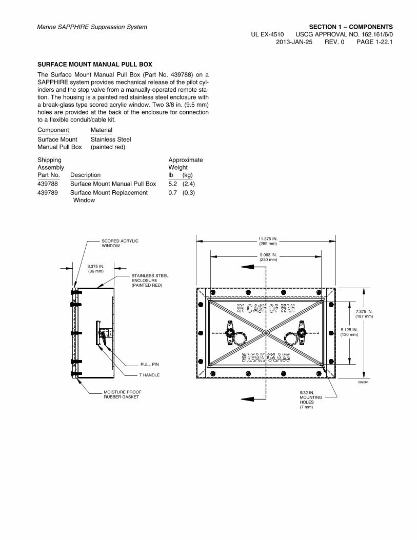
SurfaCE MOuNT MaNuaL PuLL BOX
The Surface Mount Manual Pull Box (Part No. 439788) on a SAPPHIRE system provides mechanical release of the pilot cyl-inders and the stop valve from a manually-operated remote sta-tion. The housing is a painted red stainless steel enclosure with a break-glass type scored acrylic window. Two 3/8 in. (9.5 mm) holes are provided at the back of the enclosure for connection to a flexible conduit/cable kit.
Component Material
Surface Mount Stainless SteelManual Pull Box (painted red)
Shipping ApproximateAssembly WeightPart No. Description lb (kg)439788 Surface Mount Manual Pull Box 5.2 (2.4)439789 Surface Mount Replacement 0.7 (0.3) Window
Marine SAPPHIRE Suppression System SECTION 1 – COMPONENTSUL EX-4510 USCG APPROVAL NO. 162.161/6/0
2013-JAN-25 REV. 0 PAGE 1-22.1
009064
9/32 IN. MOUNTING HOLES(7 mm)
7.375 IN.(187 mm)
5.125 IN.(130 mm)
3.375 IN.(86 mm)
11.375 IN.(289 mm)
9.063 IN.(230 mm)
STAINLESS STEEL ENCLOSURE (PAINTED RED)
SCORED ACRYLIC WINDOW
MOISTURE PROOF RUBBER GASKET
PULL PIN
T HANDLE

fLuSH MOuNT MaNuaL PuLL BOX
The Flush Mount Manual Pull Box (Part No. 439790) on a SAPPHIRE system provides mechanical release of the pilot cylinders and the stop valve from a manually-operated remote station. The housing is a painted red stainless steel enclosure with a break-glass type scored acrylic window. Two 3/8 in. (9.5 mm) holes are provided at the back of the enclosure for connec-tion to a flexible conduit/cable kit.
Component MaterialFlush Mount Stainless SteelManual Pull Box (painted red)
Shipping ApproximateAssembly WeightPart No. Description lb (kg)
439790 Flush Mount Manual Pull Box 5.6 (2.5)439791 Flush Mount Replacement 1.1 (0.5) Window
SECTION 1 – COMPONENTSUL EX-4510 USCG APPROVAL NO. 162.161/6/0 PAGE 1-22.2 REV. 0 2013-JAN-25
Marine SAPPHIRE Suppression System
009065
9/32 IN. MOUNTING HOLES(7 mm)
9.375 IN.(238 mm)
3.375 IN.(86 mm)
13.375 IN.(340 mm)
12.625 IN.(321 mm)
8.625 IN.(219 mm)
STAINLESS STEEL ENCLOSURE (PAINTED RED)
MOISTURE PROOF RUBBER GASKET
PULL PIN
T HANDLE

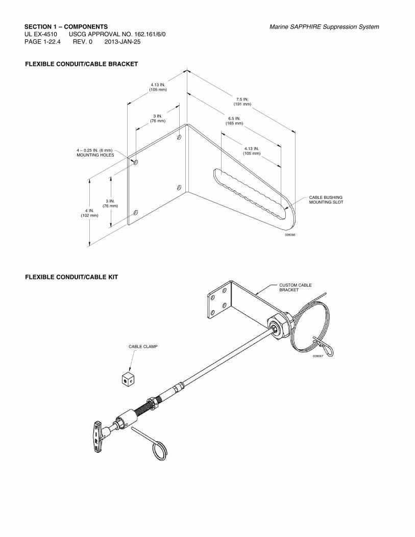
fLEXIBLE CONDuIT/CaBLE KIT
The Flexible Conduit/Cable is used to attach the surface mount manual pull box or flush mount manual pull box to pilot cylinder valves and the stop valve. Flexible Conduit/Cable Kits are avail-able in lengths from 6 ft to 100 ft (1.8 m to 30.5 m).
The flexible conduit/cable bracket is a stainless steel bracket used to secure the flexible conduit end in applications where a CPM actuator is not operated by the flexible cable.
Shipping ApproximateAssembly WeightPart No. Description lb (kg)
439996 Flexible Conduit/Cable Bracket 0.9 (0.4)439792 Flexible Conduit/Cable Kit – 6 ft (1.8 m) 1.0 (0.4)439793 Flexible Conduit/Cable Kit – 8 ft (2.4 m) 1.1 (0.5)439794 Flexible Conduit/Cable Kit – 10 ft (3.0 m) 1.2 (0.6)439795 Flexible Conduit/Cable Kit – 12 ft (3.7 m) 1.4 (0.6)439796 Flexible Conduit/Cable Kit – 14 ft (4.3 m) 1.5 (0.7)439797 Flexible Conduit/Cable Kit – 16 ft (4.9 m) 1.6 (0.7)439798 Flexible Conduit/Cable Kit – 18 ft (5.5 m) 1.8 (0.8)439799 Flexible Conduit/Cable Kit – 20 ft (6.1 m) 1.9 (0.9)439800 Flexible Conduit/Cable Kit – 22 ft (6.7 m) 2.0 (0.9)439801 Flexible Conduit/Cable Kit – 24 ft (7.3 m) 2.1 (1.0)439885 Flexible Conduit/Cable Kit – 25 ft (7.6 m) 2.2 (1.0)439802 Flexible Conduit/Cable Kit – 26 ft (7.9 m) 2.3 (1.0)439803 Flexible Conduit/Cable Kit – 28 ft (8.5 m) 2.4 (1.1)439804 Flexible Conduit/Cable Kit – 30 ft (9.1 m) 2.5 (1.2)439805 Flexible Conduit/Cable Kit – 32 ft (9.6 m) 2.7 (1.2)439806 Flexible Conduit/Cable Kit – 34 ft (10.4 m) 2.8 (1.3)439807 Flexible Conduit/Cable Kit – 36 ft (11.0 m) 2.9 (1.3)439808 Flexible Conduit/Cable Kit – 38 ft (11.6 m) 3.1 (1.4)439809 Flexible Conduit/Cable Kit – 40 ft (12.2 m) 3.2 (1.4)439810 Flexible Conduit/Cable Kit – 42 ft (12.8 m) 3.3 (1.5)439811 Flexible Conduit/Cable Kit – 44 ft (13.4 m) 3.4 (1.6)439812 Flexible Conduit/Cable Kit – 46 ft (14.0 m) 3.6 (1.6)439813 Flexible Conduit/Cable Kit – 50 ft (15.2 m) 3.8 (1.7)439814 Flexible Conduit/Cable Kit – 52 ft (15.8 m) 4.0 (1.8)439815 Flexible Conduit/Cable Kit – 55 ft (16.8 m) 4.2 (1.9)439816 Flexible Conduit/Cable Kit – 60 ft (18.2 m) 4.5 (2.0)439817 Flexible Conduit/Cable Kit – 65 ft (19.8 m) 4.8 (2.2)439818 Flexible Conduit/Cable Kit – 70 ft (21.3 m) 5.1 (2.3)439819 Flexible Conduit/Cable Kit – 75 ft (22.9 m) 5.5 (2.5)439820 Flexible Conduit/Cable Kit – 80 ft (24.4 m) 5.8 (2.6)439821 Flexible Conduit/Cable Kit – 85 ft (25. 9 m) 6.1 (2.8)439822 Flexible Conduit/Cable Kit – 90 ft (27.4 m) 6.4 (2.9)439823 Flexible Conduit/Cable Kit – 95 ft (29.0 m) 6.8 (3.1)439824 Flexible Conduit/Cable Kit – 100 ft (30.5 m) 7.1 (3.2)
Marine SAPPHIRE Suppression System SECTION 1 – COMPONENTSUL EX-4510 USCG APPROVAL NO. 162.161/6/0
2013-JAN-25 REV. 0 PAGE 1-22.3
SECTION 1 – COMPONENTSUL EX-4510 USCG APPROVAL NO. 162.161/6/0 PAGE 1-22.4 REV. 0 2013-JAN-25
Marine SAPPHIRE Suppression System
009067
CUSTOM CABLE BRACKET
CABLE CLAMP
fLEXIBLE CONDuIT/CaBLE KIT
009066
CABLE BUSHING MOUNTING SLOT
4 – 0.25 IN. (6 mm) MOUNTING HOLES
3 IN.(76 mm)
3 IN.(76 mm)
4 IN.(102 mm)
4.13 IN.(105 mm)
4.13 IN.(105 mm)
7.5 IN.(191 mm)
6.5 IN.(165 mm)
fLEXIBLE CONDuIT/CaBLE BraCKET

Marine SAPPHIRE Suppression System SECTION 1 – COMPONENTSUL EX-4510 USCG APPROVAL NO. 162.161/6/0
2013-JAN-25 REV. 2 PAGE 1-23
CaBLE WITH SWaGED END fITTING
The 1/16 in. diameter cable is used to attach remote manual pull boxes to cylinder valves, pull equalizers and control boxes. The cable is constructed of stranded, stainless steel wire. The cable is available in lengths of 50, 100, and 150 ft (15.2, 30.5, and 45.7 m). The cable assemblies include a brass swaged end fitting for attaching to the remote pull box.
The cable clamp is used to create a loop in the wire rope for attachment of the wire rope to a lever release actuator.
The Flared End Fitting provides a smooth transition on the end of a pipe run for the pull cable. When the wire rope exits the pipe to connect to lever actuators on pilot cylinders, stop valves, or globe valves the fitting prevents chaffing of the wire rope due to sharp edges on the end of the pipe. Use the flared end fitting on pipe ends any time the wire rope extends beyond the piping.
Component Material
Cable Stainless Steel Swaged Fitting Brass Cable Assembly
ShippingAssemblyPart No. Description
42104 50 ft (15.2 m) 1/16 in. (16 mm) Cable with Swaged End Fitting
42109 100 ft (30.5 m) 1/16 in. (16 mm) Cable with Swaged End Fitting
42113 150 ft (45.7 m) 1/16 in. (16 mm) Cable with Swaged End Fitting
45333 1/16 in. (16 mm) Cable Clamp
40060 Flared End Fitting
Note: The strength of the end fitting exceeds the breaking point of the cable.
000689a
000689b
SLOT IN COUPLING FOR INSTALLATION OF CABLE END FITTING
HANDLE
CABLE END (BRASS)
COUPLING
STAINLESS STEEL CABLE WITH SWAGED CABLE END FOR PULL BOX, CABLE END HAVING RED PAINT MARK

SECTION 1 – COMPONENTSUL EX-4510 USCG APPROVAL NO. 162.161/6/0 PAGE 1-24 REV. 1 2013-JAN-25
Marine SAPPHIRE Suppression System
CaBLE WITH SWaGED END fITTING (CONTINuED)
ALLEN HEADSET SCREW(10-32 X 1/4 IN. HEX OVAL POINT)
1/16 IN. CABLE
CABLE CLAMP
1/2 IN.(13 mm)
1/2 IN.(13 mm)
1/4 IN.(6 mm)
CaBLE CLaMP (ParT NO. 45333)
Material: Brass per SAE No. 72
000693
fLarED END fITTING (ParT NO. 40060)
3/8 IN.STANDARD PIPE THREAD
27/64 IN.(11 mm)
1 IN.(25 mm)
7/8 IN. HEX(22 mm)

Marine SAPPHIRE Suppression System SECTION 1 – COMPONENTSUL EX-4510 USCG APPROVAL NO. 162.161/6/0
2013-JAN-25 REV. 2 PAGE 1-25
COrNEr PuLLEy
The corner pulley is required on a SAPPHIRE system whenever a mechanical release pull cable run involves a change in direc-tion. Corner pulleys are installed as part of the cable housing (pipe) and provide 90° direction changes with minimal force loss and no induced kinking.
The corner pulley is made of forged brass and is threaded for 3/8 in. NPT pipe. The pulley is watertight and is designed for location inside or outside the protected space.
A two-piece adaptor consisting of a Coupling Nut and a Hex Nipple is available to simplify the installation. The coupling nut has a 3/8 in.-18 NPT female thread on one end and a 5/8 in.-18 left-hand female thread on the other. The hex nipple has a 3/8 in.-18 NPT male thread on one end, and a 5/8 in.-18 left-hand male thread on the other.
Installation is accomplished by first threading the male NPT end of the hex nipple into the corner pulley. Then the female 3/8 in.-18 NPT end of the coupling nut can be engaged onto the 3/8 in. pipe at the same time that the male 5/8 in.-18 left-hand thread of the hex nipple and female 5/8 in.-18 left-hand thread of the hex nipple are engaged into each other. This will allow the two pieces to be pulled together as the coupling nut is tightened.
ThreadComponent Material Size/Type
Corner Pulley – Brass 3/8 in. NPTBrass
Thread Adaptor Brass —
ShippingAssemblyPart No. Description
45515 Brass Corner Pulley (brass wheel)
40696 Thread Adaptor – right/left hand
fOrGED BraSS WaTErTIGHT COrNEr PuLLEy, SHEaVE TyPE (ParT NO. 45515)
2 11/16 IN.(68 mm)
3/8 IN. NPT
LEAD-CLADCOPPERGASKET
3/8 IN. PIPE
REMOVABLEFACE FORRUNNING CABLE
ADAPTORTHREADADAPTOR
000690b
000690a
1 5/32 IN.(29 mm)
4 3/16 IN.(106 mm)
THrEaD aDaPTOr (ParT NO. 40696)
007043
3/8 IN. – 18 NPT MALE
3/8 IN. – 18 NPT FEMALE
COUPLING NUT
5/8 IN. – 18 LEFT-HAND MALE
5/8 IN. – 18 LEFT-HAND FEMALE
HEX NIPPLE
SECTION 1 – COMPONENTSUL EX-4510 USCG APPROVAL NO. 162.161/6/0 PAGE 1-26 REV. 2 2013-JAN-25
Marine SAPPHIRE Suppression System
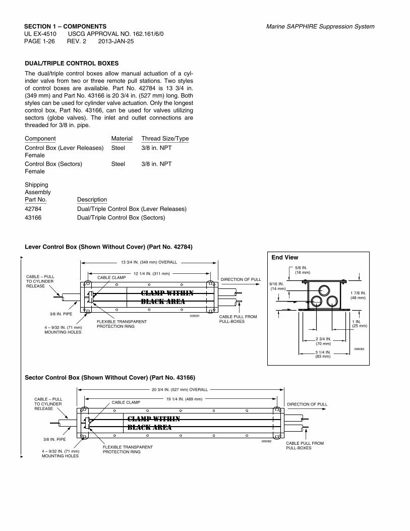
DuaL/TrIPLE CONTrOL BOXES
The dual/triple control boxes allow manual actuation of a cyl-inder valve from two or three remote pull stations. Two styles of control boxes are available. Part No. 42784 is 13 3/4 in. (349 mm) and Part No. 43166 is 20 3/4 in. (527 mm) long. Both styles can be used for cylinder valve actuation. Only the longest control box, Part No. 43166, can be used for valves utilizing sectors (globe valves). The inlet and outlet connections are threaded for 3/8 in. pipe.
Component Material Thread Size/Type
Control Box (Lever Releases) Steel 3/8 in. NPT FemaleControl Box (Sectors) Steel 3/8 in. NPT Female
ShippingAssemblyPart No. Description
42784 Dual/Triple Control Box (Lever Releases)43166 Dual/Triple Control Box (Sectors)
Sector Control Box (Shown Without Cover) (Part No. 43166)
FLEXIBLE TRANSPARENT PROTECTION RING
DIRECTION OF PULL
CABLE PULL FROM PULL-BOXES
CABLE – PULL TO CYLINDER RELEASE
3/8 IN. PIPE
4 – 9/32 IN. (71 mm)MOUNTING HOLES
CABLE CLAMP
009082
20 3/4 IN. (527 mm) OVERALL
19 1/4 IN. (489 mm)
5/8 IN. (16 mm)
1 7/8 IN. (48 mm)
9/16 IN. (14 mm)
1 IN. (25 mm)
2 3/4 IN.(70 mm)
3 1/4 IN. (83 mm)
End View
009083
Lever Control Box (Shown Without Cover) (Part No. 42784)
FLEXIBLE TRANSPARENT PROTECTION RING
DIRECTION OF PULL
CABLE PULL FROM PULL-BOXES
CABLE – PULL TO CYLINDER RELEASE
3/8 IN. PIPE
4 – 9/32 IN. (71 mm)MOUNTING HOLES
CABLE CLAMP
009081
13 3/4 IN. (349 mm) OVERALL
12 1/4 IN. (311 mm)

Marine SAPPHIRE Suppression System SECTION 1 – COMPONENTSUL EX-4510 USCG APPROVAL NO. 162.161/6/0
2013-JAN-25 REV. 2 PAGE 1-27
rEMOTE CaBLE PuLL EQuaLIZEr
The remote cable pull equalizer is used in systems where man-ual actuation of the pilot cylinder valve and operation of a stop valve must be accomplished at the same time. The pull equal-izer is mounted in the remote pull station cable line. By pulling the remote pull box, the cable attached to the pull equalizer will pull the internal cable clamp in the pull equalizer which in turn will pull the cables attached to the cylinder valve and stop valve, causing them to operate. Two styles of pull equalizers are avail-able. Part No. 42791 is 13 3/4 in. (349 mm) long and Part No. 43168 is 20 3/4 in. (527 mm). Only the longest equalizer, Part No. 43168, can be used for valves utilizing sectors. The inlet and outlet connections are threaded for 3/8 in. pipe.
Component Material Thread Size/Type
Pull Equalizer (Lever Releases) Steel 3/8 in. NPT FemalePull Equalizer (Sectors) Steel 3/8 in. NPT Female
ShippingAssemblyPart No. Description
42791 Remote Cable Pull Equalizer (Lever Releases)43168 Remote Cable Pull Equalizer (Sectors)
END VIEW
3 1/4 IN.(83 mm)
2 3/4 IN.(70 mm)
1 7/8 IN.(48 mm)
11/16 IN.(17 mm)
REMOVABLE COVER
1 IN.(25 mm)
009086
Lever Equalizer Box (Shown Without Cover) (Part No. 42791)
12 1/4 IN.(311 mm)
13 3/4 IN. (349 mm)(OVERALL)
DIRECTION OF PULL
009084 CABLE TO PULL BOXFLEXIBLE TRANSPARENT
PROTECTION RING
CABLE CLAMP
4 – 9/32 IN. (71 mm)MOUNTING HOLES
CABLE FROM CYLINDER AND VALVE RELEASES
3/8 IN. PIPE
Sector Equalizer Box (Shown Without Cover) (Part No. 43168)
19 1/4 IN. (489 mm)
20 3/4 IN. (527 mm)(OVERALL)
DIRECTION OF PULL
CABLE TO PULL BOX
FLEXIBLE TRANSPARENTPROTECTION RING
CABLE CLAMP
CABLE FROM CYLINDER AND VALVE RELEASES
4 – 9/32 IN. (71 mm)MOUNTING HOLES
3/8 IN. PIPE 009085

SECTION 1 – COMPONENTSUL EX-4510 USCG APPROVAL NO. 162.161/6/0 PAGE 1-28 REV. 2 2013-JAN-25
Marine SAPPHIRE Suppression System
MarINE aCTuaTION STaTION – TWO STEP – (S.O.L.a.S.)
The marine actuation station is used to release the system pilot cylinders by means of compressed nitrogen gas. This is accom-plished by pulling the operating handle marked CYLINDER RELEASE which punctures the nitrogen cartridge, allowing the gas to flow to a pilot port located on the pilot cylinders, and pulling the operating handle marked VALVE RELEASE which punctures the nitrogen cartridge, allowing the gas to flow to a pressure operated stop valve.
The marine actuation station comes equipped with 1/4 in. stain-less steel compression fittings for attaching 1/4 in. O.D. stainless steel tubing. The enclosure is rainproof, constructed of 16 ga. galvanized steel and is equipped with a draw pull catch.
Actuation pressure is achieved by means of an LT-20-L Nitrogen cartridge (Part No. 7012) with a height of 7 7/8 in. (200 mm) and
a diameter of 2 1/2 in. (64 mm) (DOT 3A2100).
Pneumatic Actuation Line Kit (Part No. 436127) must be used in actuation line of stop valves.
Component Material FinishMarine Actuation Station – Steel Red Two Step Epoxy PaintOptional Microswitch (Part No. 426460) must be ordered sep-arately to supply electrical contacts for the purpose of sound-ing an alarm when actuation station door is opened.
ShippingAssemblyPart No. Description
418731 Marine Actuation Station – Two Step7012 LT-20-L DOT 3A2100 Nitrogen Cartridge
001382
MaXIMuM LENGTH ruN (fEET) 0 50 100 150 200 250 300
Wa
LL
TH
ICK
NE
SS
(IN
CH
ES
)
.028
.035
.049
.065
58
67
94
150
.020
.025
.030
.035
.040
.045
.050
.055
.060
.065
.070
1/4 IN. STAINLESS STEEL TUBE
MaXIMuM LENGTH Of aCTuaTION TuBING frOM rEMOTE STaTION TO CyLINDErS
Note: Pneumatic Actuation Line Kit (Part No. 436127) must be utilized in actuation line of stop valves. Vent Line (Part No. 42175) must be utilized in actuation line of pilot cylinder valve.
INSTRUCTIONCHART
TO VALVE
TO CYLINDER
PULL CATCH
NITROGENCARTRIDGE
ELECTrICaL raTING fOr 426460 .5a @ 125VDC000694
10 IN.(254 mm)
VALVE
REL
CYLINDER
REL
COMPRESSIONFITTING FOR 1/4 IN. OD S.S. TUBE
12 IN.(305 mm)
6 IN.(152 mm)
3 IN.(76 mm)
13 IN.(330 mm)

Marine SAPPHIRE Suppression System SECTION 1 – COMPONENTSUL EX-4510 USCG APPROVAL NO. 162.161/6/0
2013-JAN-25 REV. 1 PAGE 1-28.1
007984
1 3/32 IN.(28 mm)
3/8 IN.(9 mm)
1 11/16 IN.(43 mm)
1 1/2 IN.(38 mm)
0.18 IN. HOLES, 2 LOCATIONS
MICrOSWITCH MOuNTING DETaIL fOr MarINE aCTuaTION STaTION
ENCLOSURE
MICROSWITCH (PART NO. 426460)
1/8 IN. PIPE, 0.75 IN. (19 mm) LONG, 2 LOCATIONS
#8 SCREW, 2 IN. (51 mm) LONG W/LOCKWASHERS AND NUT, 2 LOCATIONS
SIDE VIEW
frONT VIEW
007980
LABEL FOR CYLINDER RELEASE
MICROSWITCH
LABEL FOR VALVE RELEASE
MICrOSWITCH MOuNTING LOCaTION
007981
MICROSWITCH
1 1/2 IN.(38 mm)
1 11/16 IN.(43 mm)
1 3/32 IN.(28 mm)
3/8 IN.(9 mm)

PAGE INTENTIONALLY LEFT BLANK
SECTION 1 – COMPONENTSUL EX-4510 USCG APPROVAL NO. 162.161/6/0 PAGE 1-28.2 REV. 1 2013-JAN-25
Marine SAPPHIRE Suppression System
Marine SAPPHIRE Suppression System SECTION 1 – COMPONENTSUL EX-4510 USCG APPROVAL NO. 162.161/6/0
2013-JAN-25 REV. 3 PAGE 1-29
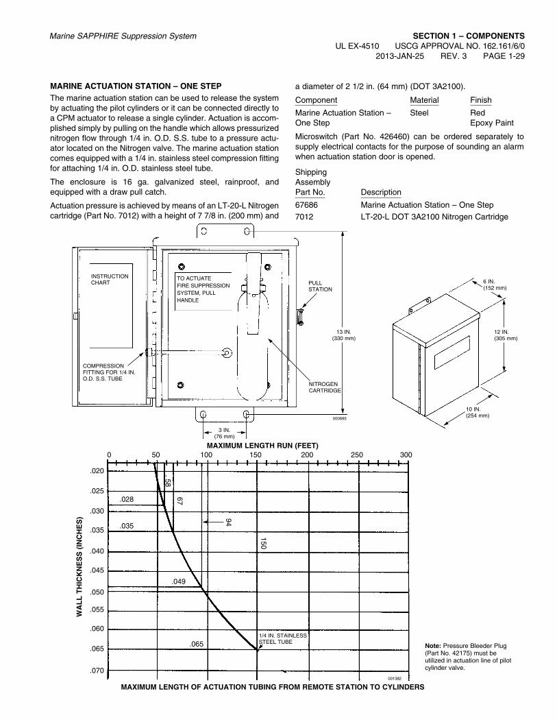
MarINE aCTuaTION STaTION – ONE STEPThe marine actuation station can be used to release the system by actuating the pilot cylinders or it can be connected directly to a CPM actuator to release a single cylinder. Actuation is accom-plished simply by pulling on the handle which allows pressurized nitrogen flow through 1/4 in. O.D. S.S. tube to a pressure actu-ator located on the Nitrogen valve. The marine actuation station comes equipped with a 1/4 in. stainless steel compression fitting for attaching 1/4 in. O.D. stainless steel tube.
The enclosure is 16 ga. galvanized steel, rainproof, and equipped with a draw pull catch.
Actuation pressure is achieved by means of an LT-20-L Nitrogen cartridge (Part No. 7012) with a height of 7 7/8 in. (200 mm) and
a diameter of 2 1/2 in. (64 mm) (DOT 3A2100).
Component Material Finish
Marine Actuation Station – Steel Red One Step Epoxy Paint
Microswitch (Part No. 426460) can be ordered separately to supply electrical contacts for the purpose of sounding an alarm when actuation station door is opened.
ShippingAssemblyPart No. Description
67686 Marine Actuation Station – One Step7012 LT-20-L DOT 3A2100 Nitrogen Cartridge
NITROGENCARTRIDGE
COMPRESSION FITTING FOR 1/4 IN. O.D. S.S. TUBE
PULL STATION
INSTRUCTIONCHART
000695
TO ACTUATE FIRE SUPPRESSION SYSTEM, PULLHANDLE
6 IN.(152 mm)
12 IN.(305 mm)
10 IN.(254 mm)
3 IN.(76 mm)
13 IN.(330 mm)
MaXIMuM LENGTH ruN (fEET) 0 50 100 150 200 250 300
Wa
LL
TH
ICK
NE
SS
(IN
CH
ES
)
1/4 IN. STAINLESS STEEL TUBE
.028
.035
.049
.065
58
67
94
150
.020
.025
.030
.035
.040
.045
.050
.055
.060
.065
.070
MaXIMuM LENGTH Of aCTuaTION TuBING frOM rEMOTE STaTION TO CyLINDErS
Note: Pressure Bleeder Plug (Part No. 42175) must be utilized in actuation line of pilot cylinder valve.
001382

SECTION 1 – COMPONENTSUL EX-4510 USCG APPROVAL NO. 162.161/6/0 PAGE 1-29.1 REV. 1 2013-JAN-25
Marine SAPPHIRE Suppression System
MICrOSWITCH MOuNTING LOCaTION
007984
1 3/32 IN.(28 mm)
3/8 IN.(9 mm)
1 11/16 IN.(43 mm)
1 1/2 IN.(38 mm)
0.18 IN. HOLES, 2 LOCATIONS
MICrOSWITCH MOuNTING DETaIL fOr MarINE aCTuaTION STaTION
ENCLOSURE
MICROSWITCH (PART NO. 426460)
1/8 IN. PIPE, 0.75 IN. (19 mm) LONG, 2 LOCATIONS
#8 SCREW, 2 IN. (51 mm) LONG W/LOCKWASHERS AND NUT, 2 LOCATIONS
SIDE VIEW
frONT VIEW
007982
MICROSWITCH
TO aCTIVaTE fIrE
SuPPrESSION SySTEM,
PuLL HaNDLE
007981
MICROSWITCH
1 1/2 IN.(38 mm)
1 11/16 IN.(43 mm)
1 3/32 IN.(28 mm)
3/8 IN.(9 mm)

Marine SAPPHIRE Suppression System SECTION 1 – COMPONENTSUL EX-4510 USCG APPROVAL NO. 162.161/6/0
2013-JAN-25 REV. 1 PAGE 1-29.2
QuarTZOID BuLB aCTuaTOr
The Quartzoid Bulb Pressure Type Automatic Release (QBA-5) actuates the system pilot cylinders or single-tank agent cylin-ders by releasing carbon dioxide through a maximum of 100 ft (30.5 m) of 1/8 in. Schedule 40 ERW pipe or stainless steel tubing. The QBA-5 is available with temperature ratings of 135, 175, and 250 °F (57, 79, and 121 °C).
Used in hazards 6000 ft3 (170 m3) and under.
Part No. Temperature
42267 135 °F (57 °C)42274 175 °F (79 °C)42276 250 °F (121 °C)
Material: Spun Steel Cylinder with Brass Release Valve
Component Dimensions: Length: 10 in. (254 mm) Width: 2 7/8 in. (73 mm) Height: 3 3/4 in. (95 mm)
Cylinder Certification: DOT3E1800
RELEASEMECHANISM
SAFETY RELIEFBURSTING DISC
TEMPERATURERATING STAMPEDHERE
QUARTZOID BULB
1/4 IN. – 18 NPT OUTLET
1/4 IN. X 1/8 IN.REDUCER NOT SUPPLIED
BRACKET
NAMEPLATE
NAMEPLATE
CARBON DIOXIDECYLINDER
001400

SECTION 1 – COMPONENTSUL EX-4510 USCG APPROVAL NO. 162.161/6/0 PAGE 1-30 REV. 3 2013-JAN-25
Marine SAPPHIRE Suppression System
PNEuMaTIC aCTuaTION LINE KIT
The Pneumatic Actuation Line Kit (Part No. 436127) is used to control the pressure in the actuation lines of the 3/4 in. isolation valve. One Pneumatic Actuation Line Kit is required for each pneumatic actuator and must be installed within 1 ft (0.3 m) of the pneumatic actuator/isolation valve. The Low Pressure Vent Plug and Safety Relief Valve are to be installed with a torque of 125 in.-lb (14 Nm). After system discharge, all pressure in the actuation line must be relieved by pulling the ring on the safety relief valve.
Part No. Description Material
436085 Low-Pressure Vent Plug Brass15677 Safety Relief Valve Brass28484 1/4 in. Close Nipple Galvanized Steel27350 1/4 in. Tee Galvanized Steel
Note 1: The low pressure vent plug cannot be ordered separately.
Note 2: CPM Actuator does not require use of this line kit.
1/4 IN. TEE
LOW PRESSURE VENT PLUG
SAFETYRELIEF VALVE
1/4 IN. CLOSE NIPPLE
1 3/4 IN.(44 mm)
008246
4 3/4 IN.(121 mm)
008334
PNEUMATIC ACTUATION LINE KIT (PART NO. 436127)
3/4 IN. PRESSURE ACTUATED ISOLATION VALVE (PART NO. 41702)
TO MARINE ACTUATION STATION
TyPICaL aPPLICaTION

Marine SAPPHIRE Suppression System SECTION 1 – COMPONENTSUL EX-4510 USCG APPROVAL NO. 162.161/6/0
2013-JAN-25 REV. 2 PAGE 1-31
MaLE BraNCH TEE (ParT NO. 31811)
The male branch tee is used primarily in manifolded systems when piping from one “slave” cylinder to the next.
Material: Brass
2 1/4 IN.(57 mm)
7/16-20
1/4 NPT
DEPTH: 9/16 IN. (14 mm)
1 15/16 IN.(49 mm)
SECTION 1 – COMPONENTSUL EX-4510 USCG APPROVAL NO. 162.161/6/0 PAGE 1-31.1 REV. 1 2013-JAN-25
Marine SAPPHIRE Suppression System
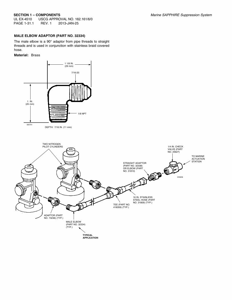
MaLE ELBOW aDaPTOr (ParT NO. 32334)
The male elbow is a 90° adaptor from pipe threads to straight threads and is used in conjunction with stainless braid covered hose.
Material: Brass
000701
1 1/8 IN.(29 mm)
7/16-20
1/8 NPT
DEPTH: 7/16 IN. (11 mm)
1 IN.(25 mm)
TEE (PART NO.418359) (TYP.)
16 IN. STAINLESS STEEL HOSE (PART NO. 31809) (TYP.)
TWO NITROGEN PILOT CYLINDERS
MALE ELBOW(PART NO. 32334) (TYP.)
ADAPTOR (PART NO. 73236) (TYP.)
1/4 IN. CHECK VALVE (PART NO. 25627)
STRAIGHT ADAPTOR (PART NO. 32338)OR ELBOW (PARTNO. 31810)
TO MARINE ACTUATION STATION
TyPICaL aPPLICaTION
003636

Marine SAPPHIRE Suppression System SECTION 1 – COMPONENTSUL EX-4510 USCG APPROVAL NO. 162.161/6/0
2013-JAN-25 REV. 1 PAGE 1-31.2
MaLE CONNECTOr (ParT NO. 32338)
This connector is used to adapt from pipe threads to straight threads, and to adapt pipe to stainless braid covered hose when it is required in a pneumatically actuated system.
Material: Brass
TEE (PART NO.418359) (TYP.)
16 IN. STAINLESS STEEL HOSE (PART NO. 31809) (TYP.)
TWO NITROGEN PILOT CYLINDERS
MALE ELBOW(PART NO. 32334) (TYP.)
ADAPTOR (PART NO. 73236) (TYP.)
1/4 IN. CHECK VALVE (PART NO. 25627)
STRAIGHT ADAPTOR (PART NO. 32338)OR ELBOW (PARTNO. 31810)
TO MARINE ACTUATION STATION
TyPICaL aPPLICaTION
003636
000704
1 1/4 IN.(32 mm)
7/16-20
1/4 NPT9/16 IN. HEX

SECTION 1 – COMPONENTSUL EX-4510 USCG APPROVAL NO. 162.161/6/0 PAGE 1-31.3 REV. 1 2013-JAN-25
Marine SAPPHIRE Suppression System
aDaPTOr
Adaptor (Part No. 73236) provides a means for attaching a standard 1/8 in. NPT thread fitting from the actuation line to the CV-98 valve.
Material: Brass per UNS-C36000
Note: Actuation piping must be vented.
008627
1.10 IN.(28 mm)
Ø 0.405 IN.(10 mm)
1/8-27 NPT MALE
1/8-27 NPT FEMALE
TEE (PART NO.418359) (TYP.)
TyPICaL aPPLICaTION
16 IN. STAINLESS STEEL HOSE (PART NO. 31809) (TYP.)
TO MARINE ACTUATION STATION OR TO QUARTZOID BULB ACTUATOR FOR “CYLINDER RELEASE”
MALE ELBOW(PART NO. 32334) (TYP.)
ADAPTOR (PART NO. 73236) (TYP.)
1/4 IN. CHECK VALVE (PART NO. 25627)
STRAIGHT ADAPTOR (PART NO. 32338)OR ELBOW (PARTNO. 31810)
TWO NITROGEN PILOT CYLINDERS
1/4 IN. NIPPLE BY INSTALLER
ACTUATION LINE VENT FITTING (PART NO. 42175)
004486

Marine SAPPHIRE Suppression System SECTION 1 – COMPONENTSUL EX-4510 USCG APPROVAL NO. 162.161/6/0
2013-JAN-25 REV. 1 PAGE 1-31.4
MaLE BraNCH TEE (ParT NO. 418359)
The male branch tee allows for the main actuation line to con-nect to the actuation port of a CV-98 valve.
Note: Actuation piping must be vented.
0082628
0.125 - 27 NPT -A
0.4375 - 20 UNF - 2 A
Ø 0.19 IN.(5 mm)
0.81 IN.(21 mm)
0.75 IN.(19 mm)
MALE BRANCH TEE1/4 TUBE RUN X 1/8 NPT BRANCH
TEE (PART NO.418359) (TYP.)
16 IN. STAINLESS STEEL HOSE (PART NO. 31809) (TYP.)
TO MARINE ACTUATION STATION OR TO QUARTZOID BULB ACTUATOR FOR “CYLINDER RELEASE”
MALE ELBOW(PART NO. 32334) (TYP.)
ADAPTOR (PART NO. 73236) (TYP.)
1/4 IN. CHECK VALVE (PART NO. 25627)
STRAIGHT ADAPTOR (PART NO. 32338)OR ELBOW (PARTNO. 31810)
1/4 IN. NIPPLE BY INSTALLER
TyPICaL aPPLICaTION
ACTUATION LINE VENT FITTING (PART NO. 42175)
004486
TWO NITROGEN PILOT CYLINDERS

SECTION 1 – COMPONENTSUL EX-4510 USCG APPROVAL NO. 162.161/6/0 PAGE 1-31.5 REV. 1 2013-JAN-25
Marine SAPPHIRE Suppression System
MaLE ELBOW (ParT NO. 31810)
It is a 90° adaptor from pipe threads to straight threads and is used commonly in manifolded systems on “master” valve and last “slave” actuator.
Material: Brass
TEE (PART NO.418359) (TYP.)
16 IN. STAINLESS STEEL HOSE (PART NO. 31809) (TYP.)
TWO NITROGEN PILOT CYLINDERS
MALE ELBOW(PART NO. 32334) (TYP.)
ADAPTOR (PART NO. 73236) (TYP.)
1/4 IN. CHECK VALVE (PART NO. 25627)
STRAIGHT ADAPTOR (PART NO. 32338)OR ELBOW (PARTNO. 31810)
TO MARINE ACTUATION STATION
TyPICaL aPPLICaTION
003636
1 7/16 IN.(37 mm)
7/16-20
1/4 IN. - 18 NPT
000702
DEPTH: 9/16 IN. (14 mm)
1 1/4 IN.(32 mm)

Marine SAPPHIRE Suppression System SECTION 1 – COMPONENTSUL EX-4510 USCG APPROVAL NO. 162.161/6/0
2013-JAN-25 REV. 1 PAGE 1-31.6
MaLE aDaPTOr (ParT NO. 570342)
The male adaptor is required to attach the 1/4 in. actuation hose to the master tank pilot port. When using the male adaptor on the master tank pilot port, a 1/4 in. pipe coupling must be used between the adaptor and the male hose thread.
004820
1/4 IN. MALE NPT
1/4 IN. MALE BSP
1.35 IN.(34 mm)

SECTION 1 – COMPONENTSUL EX-4510 USCG APPROVAL NO. 162.161/6/0 PAGE 1-32 REV. 2 2013-JAN-25
Marine SAPPHIRE Suppression System
PILOT CyLINDEr fLEXIBLE DISCHarGE BEND
The valve Flexible Discharge Bend (Part No. 427082) is a 5/8 in. (16 mm) I.D. extra-heavy flexible hose which connects the valve discharge outlet to the pilot cylinder manifold. The discharge bend has a special female thread for connecting to the valve outlet and a male 1/2 in. NPT thread for connecting to the fixed piping or manifold. The discharge bend will withstand a pressure of 9000 psi (620.5 bar). Its flexible connection allows for easy alignment. Each bend has a built-in check valve that prevents loss of agent should the system discharge while any cylinder is removed.
Thread Size/TypeComponent Material Valve End Manifold End
5/8 in. Flexible SAE 100 R2 Special to 1/2 in. NPT Discharge Bend Hose Type AT mate with Male CV-98 Valve
ShippingAssemblyPart No. Description
427082 Flexible Discharge Bend437919 Gasket42430 Gasket (for previous adaptor design)
18 7/8 IN.(479 mm)
MANIFOLD END
000658
1/2 IN. NPTMALE COUPLING
FEMALE ADAPTOR (SWIVEL, BRASS)
VALVE END
CHECKSWAGE ON
WASHER
Note: The figures below identify the previous and current adaptor designs and required gasket part numbers.
Previous Adaptor Design (Required Gasket – Part No. 42430)
New Adaptor Design (Required Gasket – Part No. 437919)

Marine SAPPHIRE Suppression System SECTION 1 – COMPONENTSUL EX-4510 USCG APPROVAL NO. 162.161/6/0
2013-JAN-25 REV. 2 PAGE 1-33
STaINLESS STEEL aCTuaTION HOSE
The Stainless Steel Actuation Hose has 7/16-20 female swivel end fittings on both ends, the same thread as the compression tees.
The 1/4 in. Stainless Steel Actuation Hose with 1/4 in. NPT x 7/16-20 end fittings is used to connect the actuation line to aux-iliary equipment such as a pressure switch or other pneumatic input devices.
Shipping assemblyPart No. Description
31809 16 in. (406 mm) Stainless Steel Hose
32335 20 in. (508 mm) Stainless Steel Hose
32336 24 in. (609 mm) Stainless Steel Hose
Shipping assemblyPart No. Description
73597 16 in. (406 mm) Stainless Steel Hose
415142 32 in. (813 mm) Stainless Steel Hose
430815 42 in. (1067 mm) Stainless Steel Hose
SEE CHART
7/16-20
000433
7/16-20
000432
SEE CHART
7/16 - 201/4 IN. NPT

SECTION 1 – COMPONENTSUL EX-4510 USCG APPROVAL NO. 162.161/6/0 PAGE 1-34 REV. 2 2013-JAN-25
Marine SAPPHIRE Suppression System
BLEEDEr PLuG
The pressure bleeder plug can be used to relieve the pressure in closed actuation lines. The plug and vent relieves the pressure through a small orifice. This slow relief of pressure does not affect the function of the actuation line.
Component Material Thread Size/Type
Bleeder Plug Brass 1/4 in. NPT Male
ShippingAssemblyPart No. Description
42175 Pressure Bleeder Plug
ORIFICE
BLEEDEr PLuG3/8 IN.(9.5 mm)
1/4 IN. NPT
001839
3/4 IN.(19 mm)

Marine SAPPHIRE Suppression System SECTION 1 – COMPONENTS
HEaDEr VENT PLuG
The header vent plug is used to release low pressure buildup that may occur in a closed system utilizing stop valves or check valves. The header vent plug should also be installed on the cylinder sides of the check valves on both main and reserve systems to relieve any pressure that may leak past the check valve and accidentally actuate the reserve system while the main system is discharging.
Closing pressure is 30 psi (2.1 bar).
Component Material Thread Size/Type
Vent Plug Body: Brass 1/2 in. NPT Male Spring: Bronze Seal: Neoprene
ShippingAssemblyPart No. Description40309 Header Vent Plug
000707
CHECK SEAL
CHECK CUP
STEM
BODY
WASHER
29/32 IN.(23 mm)7/8 IN.
(22 mm)

SECTION 1 – COMPONENTSUL EX-4510 USCG APPROVAL NO. 162.161/6/0 PAGE 1-36 REV. 2 2013-JAN-25
Marine SAPPHIRE Suppression System
1/2 IN. MaNIfOLD SafETy rELIEf ruPTurE DISC aSSEMBLy
The manifold safety relief rupture disc assembly is designed to open at a predetermined set pressure to protect piping and equipment from being subjected to pressure that exceeds their design limits. The safety relief rupture disc assembly is non-clos-ing and requires replacement once activated.
Burst Pressure: 2,900 – 3,360 psi (200 – 232 bar)
Component Material1/2 in. Manifold Safety Relief Brass Rupture Disc Assembly
ShippingAssemblyPart No. Description
418378 1/2 in. Manifold Safety Relief Rupture Disc Assembly
SAFETY DISK NUT
1/2 – 14 NPT
002740
1/2 IN. MaNIfOLD SafETy rELIEf ruPTurE DISC aSSEMBLy
7/8 IN.(22 mm)
1 1/2 IN.(38 mm)

Marine SAPPHIRE Suppression System SECTION 1 – COMPONENTSUL EX-4510 USCG APPROVAL NO. 162.161/6/0
2013-JAN-25 REV. 2 PAGE 1-37
PrE-DISCHarGE TIME DELay
The system discharge must be delayed for a short time following actuation. This is usually in areas where it is necessary to evac-uate personnel prior to discharge. A manual release is incorpo-rated on the time delay valve to allow instant override of the time delay. The length of delay is factory set and is not adjustable.
The time delay assembly uses nitrogen pressure to power the factory-set delay mechanism. Install the assembly in the discharge piping, either directly after the control (pilot) cylinder or further along the piping. The assembly will operate in any mounting orientation; however, flow direction is marked on the valve and must be observed for installation. After the discharge is complete, pressure in the assembly slowly returns to normal and closes the time delay valve.
ShippingAssemblyPart No. Description
426170 60 Second time delay54169 30 Second time delay
Component Material
Valve Brass Accumulator Steel (Sch. 80 Pipe)Time Delay Assembly
000699
5 1/2 IN.(140 mm)
3/4 IN. – 14 NPT BOTH SIDES
5 7/8 IN.(149 mm)
23 3/8 IN.(594 mm)

29 SECOND TIME DELay aSSEMBLy
Note: Only to be installed in systems utilizing a 42 ft3 nitrogen pilot cylinder. System requirements found in Section 13 – appendix 2.
The 29 Second Time Delay Assembly uses nitrogen from an LT-10-R cartridge (Part No. 423423) to power the factory-set delay mechanism. A manual release is incorporated on the time delay valve to allow instant delay override.
Shipping ApproximateAssembly WeightPart No. Delay Setting (Seconds) lb (kg)
439878 29 34.8 (15.8)
SECTION 1 – COMPONENTSUL EX-4510 USCG APPROVAL NO. 162.161/6/0 PAGE 1-37.1 REV. 0 2013-JAN-25
Marine SAPPHIRE Suppression System
008608
7 1/4 IN.(184 mm)
12 5/16 IN.(313 mm)
8 1/16 IN.(205 mm)
6 3/4 IN.(171 mm)
8 13/16 IN.(224 mm)
2 9/16 IN.(65 mm)

PAGE INTENTIONALLY LEFT BLANK
Marine SAPPHIRE Suppression System SECTION 1 – COMPONENTSUL EX-4510 USCG APPROVAL NO. 162.161/6/0
2013-JAN-25 REV. 0 PAGE 1-37.2

SECTION 1 – COMPONENTSUL EX-4510 USCG APPROVAL NO. 162.161/6/0 PAGE 1-38 REV. 2 2013-JAN-25
Marine SAPPHIRE Suppression System
3/4 IN. PrESSurE aCTuaTED STOP/ISOLaTION VaLVE (ParT NO. 418596)
Material: Brass
The 3/4 in. pressure actuated stop/isolation valve is used in con-junction with pilot actuation systems, and can be used to isolate pressure operated alarms and shut down devices.
There are three methods of opening the 3/4 in. pressure actu-ated valve:
1. By applying pressure into the 1/8 in. NPT port located in the rear of the valve.
2. By applying pressure at the outlet side of the valve.
3. By pulling on the manual release handle located on the front of the valve.
The 3/4 in. pressure actuated stop/isolation valve is designed to withstand a minimum burst pressure of 6000 psi (413.7 bar).
MANUAL VALVERELEASE HANDLE
OUTLET3/4 IN. – 14 NPT
INLET3/4 IN. – 14 NPT
ACTUATION STATIONINLET 1/8 IN. –27 NPT
006231
5 7/8 IN.(149 mm)
3 9/16 IN.(90 mm)

Marine SAPPHIRE Suppression System SECTION 1 – COMPONENTSUL EX-4510 USCG APPROVAL NO. 162.161/6/0
2013-JAN-25 REV. 2 PAGE 1-39
CHECK VaLVES – THrEaDED
Check valves are used in main/reserve systems. On main/reserve systems, the check valve prevents pressurization of the reserve system manifold by blocking the flow of SAPPHIRE System agent from the main system to the reserve system. The check valve allows gas flow from the reserve (if actuated) to pass through into the distribution piping. Only the cylinders needed for the particular hazard are activated.
The threaded check valves are available in sizes from 1/4 in. through 2 in.
Check Valve – Threaded Dimension A Dimension BValve Size in. (mm) in. (mm) Weight1/2 in. 3 (76) 2 5/8 (66) 2 lb (0.9 kg)3/4 in. 3 5/8 (92) 3 1/8 (79) 4 lb (1.8 kg)1 in. 4 1/8 (104) 3 3/4 (95) 7 lb (3.0 kg)1 1/4 in. 5 (127) 4 1/2 (114) 10 lb (8.7 kg)1 1/2 in. 5 1/2 (139) 5 1/8 (130) 13 lb (5.9 kg)2 in. 6 1/2 (165) 6 7/16 (164) 15 lb (6.8 kg)
ShippingAssemblyPart No. Description25627 1/4 in. Check Valve (pkg. of 2)40860 1/2 in. Check Valve40852 3/4 in. Check Valve41470 1 in. Check Valve41549 1 1/4 in. Check Valve41463 1 1/2 in. Check Valve40649 2 in. Check Valve
Component Material Thread Size/Type Body TypeCheck Valve Brass 1/4 – 18 NPT Female ThreadedCheck Valve Bronze 1/2-14 NPT Female Threaded Check Valve Bronze 3/4-14 NPT Female ThreadedCheck Valve Bronze 1 - 11 1/2 NPT Female Threaded Check Valve Bronze 1 1/4 - 11 1/2 Threaded NPT FemaleCheck Valve Bronze 1 1/2 - 11 1/2 Threaded NPT FemaleCheck Valve Bronze 2 - 11 1/2 NPT Female Threaded
A
B
BONNET
BODY
SPRING
CHECK
DIRECTIONOF FLOW
002737

SECTION 1 – COMPONENTSUL EX-4510 USCG APPROVAL NO. 162.161/6/0 PAGE 1-39.1 REV. 1 2013-JAN-25
Marine SAPPHIRE Suppression System
1/4 IN. CHECK VaLVE (ParT NO. 25627)
Material: Brass
Maximum operating pressure: 3000 psi (206.8 bar)
Minimum burst pressure: 7500 psi (517.1 bar)
1/4 IN. NPT1/4 IN. NPT
007979
2 IN.(51 mm)
004486
TEE (PART NO.418359) (TYP.)
16 IN. STAINLESS STEEL HOSE (PART NO. 31809) (TYP.)
TO MARINE ACTUATION STATION OR TO QUARTZOID BULB ACTUATOR FOR “CYLINDER RELEASE”
MALE ELBOW (PART NO. 32334) (TYP.)
ADAPTOR (PART NO. 73236) (TYP.)
1/4 IN. CHECK VALVE (PART NO. 25627)
STRAIGHT ADAPTOR (PART NO. 32338)OR ELBOW (PARTNO. 31810)
1/4 IN. NIPPLE BY INSTALLER
ACTUATION LINE VENT FITTING (PART NO. 42175)
TWO NITROGEN PILOT CYLINDERS

Marine SAPPHIRE Suppression System SECTION 1 – COMPONENTSUL EX-4510 USCG APPROVAL NO. 162.161/6/0
2013-JAN-25 REV. 1 PAGE 1-39.2
1/2 IN. BaLL VaLVE WITH MaNuaL LOCKING DEVICE
A B C D E Wgt. Part No. Description in. (mm) in. (mm) in. (mm) in. (mm) in. (mm) lb (kg)
416910 1/2 in. Ball Valve 2.6 (66) 2.0 (50) 0.5 (13) 4.0 (102) 1.9 (48) 1.0 (0.5)
Material: Body – Stainless Steel Ball – Stainless Steel Stem – Stainless Steel Seat – Teflon Stem Seal – Teflon Handle and Misc. Hardware – Stainless Steel
Part No.: 416910
A
D
B
E
C

1/4 IN. STOP VaLVE
Note: Only to be installed in systems utilizing a 42 ft3 nitrogen pilot cylinder. System requirements found in Section 13 – appendix 2.
Stop valves are used to manually control the release of system agent into a hazard area. These valves are operated manually, either by the use of the hand lever on the valve or by means of a remote manual pull box which will operate the hand lever on the valve. Stop valves can be used as a safety feature, preventing the release of agent, either because of a false discharge or to allow the occupants enough time to exit the area prior to the valve being manually opened. Stop valves are installed in pilot lines only.
A B C D E F Weight ThreadPart No. Description in. (mm) in. (mm) in. (mm) in. (mm) in. (mm) in. (mm) lb (kg) Size/Type
439777 1/4 in. Stop Valve 2.5 (64) 1.5 (39) 0.4 (9) 4.8 (122) 4.4 (112) 1.5 (38) 0.9 (0.4) 1/4 in. NPT Female
Material: Body – Stainless Steel Ball – Stainless Steel Stem – Stainless Steel Seat – Delrin Stem Seal – PTFE Handle and Misc. Hardware – Stainless Steel
Part No.: 439777
SECTION 1 – COMPONENTSUL EX-4510 USCG APPROVAL NO. 162.161/6/0 PAGE 1-39.3 REV. 0 2013-JAN-25
Marine SAPPHIRE Suppression System
A
D
F
E
B
C
009068
PAGE INTENTIONALLY LEFT BLANK
Marine SAPPHIRE Suppression System SECTION 1 – COMPONENTSUL EX-4510 USCG APPROVAL NO. 162.161/6/0
2013-JAN-25 REV. 0 PAGE 1-39.4

SECTION 1 – COMPONENTSUL EX-4510 USCG APPROVAL NO. 162.161/6/0 PAGE 1-40 REV. 1 2013-JAN-25
Marine SAPPHIRE Suppression System
GLOBE VaLVES aND CONTrOLS
Globe valves are used to either manually control the flow of SAPPHIRE System agent into a hazard area or to manually control the flow into one of several hazards being protected by a common bank of SAPPHIRE System cylinders. These valves are operated manually, either by the use of a hand lever attached directly to the valve or by means of a remote manual pull box which will operate a sector attached to the valve. Globe valves can be used as a safety feature, keeping the flow of agent from entering a hazard area, either because of a false discharge or to allow the occupants enough time to exit the area prior to the valve being manually opened. The valves are available in 1/2 in. and 3/4 in. sizes. Each size can be used with a hand lever or a sector. Globe valves are installed in pilot lines only.
Component Material Thread Size/TypeGlobe Valve Forged Brass 1/2 in. NPT FemaleGlobe Valve Forged Brass 3/4 in. NPT Female
Shipping Assembly Part No. Description41451 1/2 in. direction/stop valve (valve only)41102 3/4 in. direction/stop valve (valve only)40248 Handle – normally open (for use with 1/2 in. valve)40267 Handle – normally open (for use with 3/4 in. valve)40238 Handle – normally closed (for use with 1/2 in. valve)40239 Handle – normally closed (for use with 3/4 in. valve)40276 Sector (for use with 1/2 in. valve)40279 Sector (for use with 3/4 in. valve)
a B C D EValve Size in. (mm) in. (mm) in. (mm) in. (mm) in. (mm)
1/2 in. 10 (254) 9 3/8 (238) 4 3/4 (121) 7/8 (22) 2 15/16 (74)3/4 in. 14 (355) 12 3/4 (323) 5 5/8 (142) 1 1/8 (28) 3 5/8 (92)
a B C DValve Size in. (mm) in. (mm) in. (mm) in. (mm)
1/2 in. 4 3/4 (121) 3 (76) 7/8 (22) 2 15/16 (74)3/4 in. 5 5/8 (142) 3 5/8 (93) 1 1/8 (28) 3 5/8 (92)
* THIS DIMENSION WITH VALVE IN OPEN POSITION
A
001427a
001427b
D
E
B
C*
PIPE
HANDLE IN OPEN POSITION
HANDLE IN NORMALLY CLOSED POSITION
000674a
000674b
CABLE CLAMP
1/16 IN. STAINLESS STEEL OR MONEL CABLE TO PULL BOX
3/4 IN. FLAREDEND FITTING
CABLE TO HAVE A SLIGHT SLACK WHEN VALVE IS IN CLOSED POSITION
PROVIDE A STOP FOR SECTOR AT THIS POINT
30°
4 3/4 IN.(121 mm)
7 11/16 IN.
(195 mm)D
3 3/8 IN.(85 mm)
6 13/16 IN.(173 mm)
A
B C
ATTACH CABLE IN “FIGURE 8 (LOOP)” BEFOREFASTENING CLAMP

Marine SAPPHIRE Suppression System SECTION 1 – COMPONENTSUL EX-4510 USCG APPROVAL NO. 162.161/6/0
2013-JAN-25 REV. 2 PAGE 1-41
STOP VaLVES
Stop valves are used in actuation piping.
When pneumatic actuation is required for the 1 in. valve, a Stackable Actuator Assembly (Part No. 428566) must be ordered separately.
Stop valves can be manually operated by mounting a Lever Actuator (Part No. 427207) directly onto the valve.
Component Material Thread Size/Type1 in. Stop Valve Bronze 1 in. NPT Female(Used for 1/2 in., 3/4 in.) and 1 in. pipe sizes)
ShippingAssemblyPart No. Description
427185 1 in. Stop Valve – threaded
Valve A B CSize Body in. (mm) in. (mm) in. (mm)1 in. Threaded – 5 1/2 (140) 2 9/16 (67) 7 (178) 1 in. NPT female
006035
A
C
1 1/8 – 18 UNEF
B

SECTION 1 – COMPONENTSUL EX-4510 USCG APPROVAL NO. 162.161/6/0 PAGE 1-42 REV. 3 2013-JAN-25
Marine SAPPHIRE Suppression System
PrESSurE-OPEraTED SIrEN
The pressure-operated siren is used to warn personnel of a sys-tem discharge. The siren is operated with the nitrogen pressure from the pilot cylinder. The siren will operate at the start of the SAPPHIRE system actuation and will continue through most of the discharge time. A pipe hanger or bracket must be installed within one foot of the siren.
ComponentSiren
MaterialBody: BrassGrill: SteelScreen: Stainless Steel
Specifications Maximum Pipe Length: – 240 ft (73.2 m) of 3/4 in. Schedule 40 pipe – 430 ft (131.1 m) of 1/2 in. Schedule 40 pipe – 675 ft (205.7 m) of 3/8 in. Schedule 40 pipe
Maximum Elbows: 30
Maximum Sirens: 5
ShippingAssemblyPart No. Description
437616 Pressure-Operated Siren
1/4 IN.NPT INLET
6.25 IN.(159 mm)
008806
0.34 IN. (9 mm) DIA. HOLE (2)
5.25 IN.(133 mm)
5.60 IN.(142 mm)
3.42 IN.(87 mm)

Marine SAPPHIRE Suppression System SECTION 1 – COMPONENTSUL EX-4510 USCG APPROVAL NO. 162.161/6/0
2013-JAN-25 REV. 2 PAGE 1-43
PrESSurE SWITCH – 3PDT
The pressure switch is operated by the SAPPHIRE agent pres-sure when the system is discharged. The pressure switch can be used to open or close electrical circuits to shut down equip-ment (single or 3-phase) or turn on lights or alarms. The housing is constructed of 16 ga. steel, painted red, and is rated IP65 for dust and water ingress. The 3/8 in. NPT brass pressure inlet is used to connect the pressure switch to the suppression system.
Minimum operating pressure is 50 psi (3.5 bar).
Thread Size/ ElectricalComponent Material Type RatingPressure Switch: Conduit Inlets: 10A, 250 VAC Switch – Nickel-plated 3/4 in. and 1/2 in. 15A, 125 VAC 3PDT Brass Housing/Cover: Pressure Inlet: 3/4 HP, C.R. 16 ga steel 3/8 in. NPT 250 VAC Plunger: Female 1-, 2-, and Stainless Steel 3-phase
Pressure Port: C37700 Brass
ShippingAssemblyPart No. Description
437900 Pressure Switch – 3PDT
008979
6.0 IN.(152 mm)
4.45 IN.(113 mm)
2.75 IN.(70 mm)
5.25 IN.(133 mm)
0089783.83 IN.(97 mm)
4.45 IN.(113 mm)
4.51 IN.(115 mm)

SECTION 1 – COMPONENTSUL EX-4510 USCG APPROVAL NO. 162.161/6/0 PAGE 1-44 REV. 1 2013-JAN-25
Marine SAPPHIRE Suppression System
PrESSurE SWITCH DPDT – EXPLOSION-PrOOf
The pressure switch is operated by the nitrogen pressure when the system is actuated. The pressure switch can be used to open or close electrical circuits to either shut down equipment or ventilation systems and turn on lights or alarms. The double pole, double throw (DPDT) pressure switch is constructed with an explosion-proof housing suitable for hazardous environ-ments. A 1/4 in. NPT pressure inlet is used to connect the 1/4 in. pipe from the pilot system.
Minimum operating pressure is 100 psi (6.9 bar).
Thread ElectricalComponent Material Size/Type RatingPressure Housing: Conduit Inlet: 10A - 125 VACSwitch Malleable 3/4 in. NPT 5A - 250 VACDPDT Iron Female Pressure Inlet: 1/4 in. NPT Female
ShippingAssemblyPart No. Description43241 Pressure Switch – DPDT
Note: Suitable for hazardous locations, Class I, Division I, Groups C, D, and Class II, Division I, Groups E, F, G.
000455
1/4 IN. PIPE CONNECTION TO SYSTEM
1/4 IN. UNION
3/8 IN. X 1/4 IN. BUSHING
NAMEPLATE
2 11/32 IN. MOUNTING HOLES
7 7/8 IN.(200 mm)
6 1/2 IN.(165 mm)
5 3/16 IN.(147 mm)
5 1/8 IN.(130 mm)
3 9/16 IN.(91 mm)
2 5/8 IN.(66 mm)
000454
5 5/8 IN.(142 mm)
3/4 IN. CONDUIT OUTLET
3/4 IN. CONDUIT OUTLET

Marine SAPPHIRE Suppression System SECTION 1 – COMPONENTSUL EX-4510 USCG APPROVAL NO. 162.161/6/0
2013-JAN-25 REV. 2 PAGE 1-45
PAGE INTENTIONALLY LEFT BLANK
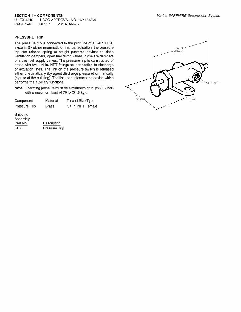
SECTION 1 – COMPONENTSUL EX-4510 USCG APPROVAL NO. 162.161/6/0 PAGE 1-46 REV. 1 2013-JAN-25
Marine SAPPHIRE Suppression System
PrESSurE TrIP
The pressure trip is connected to the pilot line of a SAPPHIRE system. By either pneumatic or manual actuation, the pressure trip can release spring or weight powered devices to close ventilation dampers, open fuel dump valves, close fire dampers or close fuel supply valves. The pressure trip is constructed of brass with two 1/4 in. NPT fittings for connection to discharge or actuation lines. The link on the pressure switch is released either pneumatically (by agent discharge pressure) or manually (by use of the pull ring). The link then releases the device which performs the auxiliary functions.
Note: Operating pressure must be a minimum of 75 psi (5.2 bar) with a maximum load of 70 lb (31.8 kg).
Component Material Thread Size/Type
Pressure Trip Brass 1/4 in. NPT Female
ShippingAssemblyPart No. Description5156 Pressure Trip
3 3/4 IN.(95 mm)
1/4 IN. NPT
000452
3 IN.(76 mm)
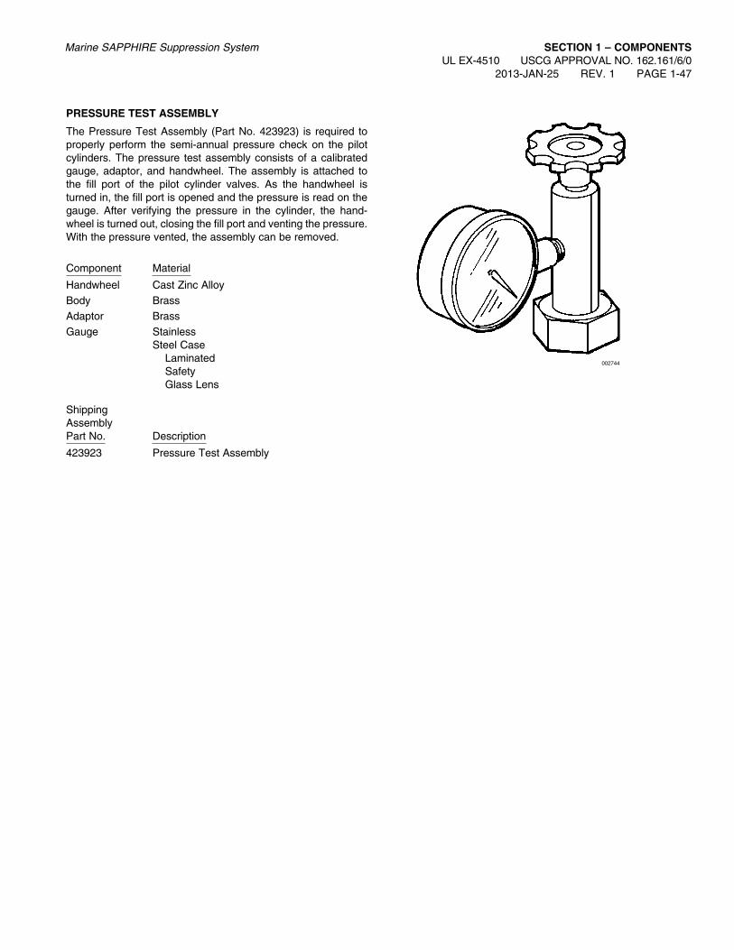
Marine SAPPHIRE Suppression System SECTION 1 – COMPONENTSUL EX-4510 USCG APPROVAL NO. 162.161/6/0
2013-JAN-25 REV. 1 PAGE 1-47
PrESSurE TEST aSSEMBLy
The Pressure Test Assembly (Part No. 423923) is required to properly perform the semi-annual pressure check on the pilot cylinders. The pressure test assembly consists of a calibrated gauge, adaptor, and handwheel. The assembly is attached to the fill port of the pilot cylinder valves. As the handwheel is turned in, the fill port is opened and the pressure is read on the gauge. After verifying the pressure in the cylinder, the hand-wheel is turned out, closing the fill port and venting the pressure. With the pressure vented, the assembly can be removed.
Component Material
Handwheel Cast Zinc AlloyBody BrassAdaptor BrassGauge Stainless Steel Case Laminated Safety Glass Lens
ShippingAssemblyPart No. Description
423923 Pressure Test Assembly
002744

SECTION 1 – COMPONENTSUL EX-4510 USCG APPROVAL NO. 162.161/6/0 PAGE 1-48 REV. 2 2013-JAN-25
Marine SAPPHIRE Suppression System
OPEraTING INSTruCTIONS PLaTE – PuLL CaBLE aCTuaTION
The operating instruction plate is available for mounting at the pull box location to instruct personnel on system actuation. The operating plate is furnished with four mounting holes for ease of installation. The plate is constructed of aluminum.
Component Material Mounting Hole Size
Operating Instructions Aluminum 1/4 in. (6 mm) Instructions – Pull Cable Actuation
ShippingAssemblyPart No. Description
41915 Operating Instructions – Pull Cable Actuation
FIRE SUPPRESSION SYSTEM
TO OPERATE:
1. BE SURE ALL DOORS OR OTHER OPENINGS ARE SECURED IN PROTECTED SPACE.
2. BREAK GLASS AND PULL HANDLE HARD IN PULL BOX MARKED “VALVE RELEASE.”
3. BREAK GLASS AND PULL HANDLE HARD IN PULL BOX MARKED “CYLINDER RELEASE.”
4. THIS SOUNDS ALARM. DISCHARGE OF GAS IS DELAYED □ SECONDS TO ALLOW PERSON-NEL TO CLEAR FIRE AREA.
7.5 IN.(191 mm)
LABEL NO. 41915
*
002748
4.5 IN.(114 mm)
.22 Ø – 4 HOLES
8 IN.(203 mm)
5 IN.(127 mm)
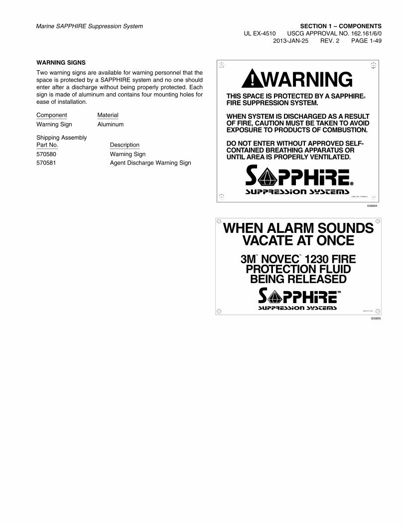
Marine SAPPHIRE Suppression System SECTION 1 – COMPONENTSUL EX-4510 USCG APPROVAL NO. 162.161/6/0
2013-JAN-25 REV. 2 PAGE 1-49
WarNING SIGNS
Two warning signs are available for warning personnel that the space is protected by a SAPPHIRE system and no one should enter after a discharge without being properly protected. Each sign is made of aluminum and contains four mounting holes for ease of installation.
Component Material
Warning Sign Aluminum
Shipping AssemblyPart No. Description
570580 Warning Sign570581 Agent Discharge Warning Sign
LABEL NO. 570581
WHEN aLarM SOuNDSVaCaTE aT ONCE3M
™
NOVEC™
1230 fIrEPrOTECTION fLuIDBEING rELEaSED
006895
006894

SECTION 1 – COMPONENTSUL EX-4510 USCG APPROVAL NO. 162.161/6/0 PAGE 1-50 REV. 2 2013-JAN-25
Marine SAPPHIRE Suppression System
NaMEPLaTE – MaIN
The ‘‘MAIN’’ nameplate is available for labeling components and/or remote pull stations to distinguish them from reserve sys-tem components. The nameplate is furnished with four mounting holes for ease of installation.
Component Material Mounting Hole SizeNameplate Aluminum 13/64 in. (5 mm)
ShippingAssemblyPart No. Description41942 Nameplate – MAIN
MaIN
5 1/2 IN.(139 mm)
4 7/8 IN.(124 mm)
1 7/8 IN.(47 mm)
2 1/2 IN.(64 mm)
5/16 IN.(8 mm)
5/16 IN.(8 mm)
PART NO. 41942
4 – 13/64 IN. (5 mm)DIAMETER HOLES
002745

Marine SAPPHIRE Suppression System SECTION 1 – COMPONENTSUL EX-4510 USCG APPROVAL NO. 162.161/6/0
2013-JAN-25 REV. 2 PAGE 1-51
NaMEPLaTE – rESErVE
The ‘‘RESERVE’’ nameplate is available for labeling compo-nents and/or remote pull stations to distinguish them from main system components. The nameplate is furnished with four mounting holes for ease of installation.
Component Material Mounting Hole SizeNameplate Aluminum 13/64 in. (5 mm)
ShippingAssemblyPart No. Description41943 Nameplate – RESERVE
rESErVE
5 1/2 IN.(139 mm)
4 7/8 IN.(124 mm)
1 7/8 IN.(48 mm)
2 1/2 IN.(64 mm)
5/16 IN.(8 mm)
5/16 IN.(8 mm)
PART NO. 41943
4 – 13/64 IN. (5 mm)DIAMETER HOLES
002745

SECTION 1 – COMPONENTSUL EX-4510 USCG APPROVAL NO. 162.161/6/0 PAGE 1-52 REV. 2 2013-JAN-25
Marine SAPPHIRE Suppression System
NOTES: