markings traffic engineering manual table of contents part
TRANSCRIPT

300 MARKINGS Traffic Engineering Manual
(July 20, 2012) October 23, 2002 3-1
TABLE OF CONTENTS
Part 3 - Markings 300 GENERAL .............................................................................................. 3-5
300-1 Introduction ................................................................................................... 3-5 300-2 Construction Projects ................................................................................... 3-5 300-3 Force Account (ODOT Operations) Work .................................................... 3-5
301 PAVEMENT & CURB MARKINGS......................................................... 3-7 301-1 General .......................................................................................................... 3-7 301-2 Selection of Pavement Marking Materials .................................................... 3-7 301-3 Pavement Marking in Incorporated Villages ................................................ 3-7 301-4 Longitudinal Markings .................................................................................. 3-8 301-5 Stop Lines ..................................................................................................... 3-8 301-6 Crosswalk Markings ..................................................................................... 3-8 301-7 Parking Space Markings ............................................................................... 3-8 301-8 Pavement Marking Words and Symbols ...................................................... 3-9 301-9 Two-Way Left-Turn Arrows ........................................................................... 3-9 301-10 Speed Measurement Markings ................................................................... 3-10 301-11 Railroad Approach Markings ...................................................................... 3-11 301-12 Speed Hump Markings ................................................................................ 3-11 301-13 Fire Hydrant Markers .................................................................................. 3-11 301-14 Chevron and Diagonal Crosshatch Markings ............................................ 3-11
301-14.1 General ...................................................................................... 3-11 301-14.2 Exit Ramps................................................................................. 3-12 301-14.3 Obstructions ............................................................................... 3-12 301-14.4 Island Markings .......................................................................... 3-12 301-14.5 Shoulders ................................................................................... 3-12
301-15 Elongated Route Shields for Pavement Markings ..................................... 3-12 301-16 Guidelines to Apply Pavement Markings over Chip Seal Surface or Chip Seal Surface Covered with Fog Seal .......................................................... 3-13 301-16.1 General ...................................................................................... 3-13 301-16.2 Surface Prep .............................................................................. 3-13 301-16.3 Work Zone Pavement Markings .................................................. 3-13 301-16.4 Striping Materials ....................................................................... 3-13
302 RAISED PAVEMENT MARKERS ........................................................ 3-15
302-1 General ........................................................................................................ 3-15 302-2 Guidelines and Placement Standards ........................................................ 3-15 302-3 Administrative Responsibilities ................................................................. 3-15 302-4 Maintenance ................................................................................................ 3-16 302-5 Raised Pavement Markers in Villages ........................................................ 3-16 302-6 Narrow and One-Lane Bridges ................................................................... 3-16
303 RESERVED FOR FUTURE INFORMATION ........................................ 3-17 304 DELINEATORS .................................................................................... 3-19
304-1 General ........................................................................................................ 3-19 304-2 Delineator Types ......................................................................................... 3-19 304-3 Application Guidelines ............................................................................... 3-19 304-4 Median Openings for Private Access ......................................................... 3-19 304-5 Narrow and One-Lane Bridges ................................................................... 3-19 304-6 Delineation for Left-Turn Lanes in Medians ............................................... 3-20 304-7 Delineators for Type E-98 Anchor Assemblies .......................................... 3-20

300 MARKINGS Traffic Engineering Manual
3-2 October 23, 2002 (July 20, 2012)
305 COLORED PAVEMENTS .................................................................... 3-21 306 BARRICADES AND CHANNELIZING DEVICES ................................ 3-21 307 BARRIER REFLECTORS .................................................................... 3-23
307-1 General ......................................................................................................... 3-23 307-2 Application on ODOT-Maintained Highways .............................................. 3-23
310 ISLANDS .............................................................................................. 3-23 320 MATERIALS AND HARDWARE .......................................................... 3-25
320-1 General ......................................................................................................... 3-25 320-2 Patented or Proprietary Materials, Specifications or Processes ............... 3-25 320-3 Purchasing Materials for Installation and Use by Local Agencies ............ 3-25 320-4 Use of Type G Sheeting............................................................................... 3-25 320-5 Barrier Reflectors ........................................................................................ 3-25
330 PLANNING / PROGRAMMING ............................................................ 3-27 340 DESIGN INFORMATION...................................................................... 3-29
340-1 General ......................................................................................................... 3-29 340-2 Preliminary Pavement Marking Plan and Stage 2 and 3 Plan Submittals . 3-29
341 PLAN PREPARATION / PRODUCTION .............................................. 3-31
341-1 General ......................................................................................................... 3-31 341-2 Pavement Marking ....................................................................................... 3-31 341-3 Work Zone Pavement Marking Materials .................................................... 3-32 341-4 Raised Pavement Markers........................................................................... 3-32 341-5 Air Speed Zone Markings ............................................................................ 3-33 341-6 Bikeway Pavement Markings ...................................................................... 3-33
342 PLAN NOTES ...................................................................................... 3-35 342-1 General ......................................................................................................... 3-35 342-2 Handicap Symbol Marking .......................................................................... 3-35 342-3 621 Raised Pavement Marker Removed ..................................................... 3-35 342-4 Air Speed Zone Marking .............................................................................. 3-36 342-5 Green Colored Pavement for Bike Lanes ................................................... 3-36
343 SPECIFICATIONS ............................................................................... 3-37 350 CONSTRUCTION ................................................................................. 3-39
350-1 General ......................................................................................................... 3-39 350-2 Work Zone Performance Evaluations ......................................................... 3-39 350-3 Raised Pavement Marker (RPM) Casting Installation ................................ 3-39 350-4 Raised Pavement Marker (RPM) Reflector Replacement ........................... 3-40 350-5 Remedial Action for Improperly Installed RPM Castings .......................... 3-41 350-6 Delineators ................................................................................................... 3-44
350-6.1 Qualified Product List (QPL) .............................................................. 3-44 350-6.2 Delineator Lateral Placement ............................................................ 3-44 350-6.3 Placement of Delineators on Curves and Tangent Sections............... 3-44 350-6.4 Delineator Installation ........................................................................ 3-44 350-6.5 Use of Delineators with Guardrail Anchor Assemblies ....................... 3-45

300 MARKINGS Traffic Engineering Manual
(July 20, 2012) October 23, 2002 3-3
350-7 Barrier Reflectors ........................................................................................ 3-45 350-7.1 Qualified Product List (QPL) ............................................................. 3-45 350-7.2 Barrier Reflector Installation ............................................................. 3-45
350-8 Pavement Markings .................................................................................... 3-45 350-8.1 General ............................................................................................ 3-45 350-8.2 Pavement Marking Materials ............................................................ 3-45 350-8.3 Application of Pavement Marking Materials....................................... 3-46 350-8.4 Data Logging System (DLS) ............................................................. 3-49 350-8.5 Construction Inspection During Pavement Marking Installation .......... 3-50
360 MAINTENANCE / OPERATIONS ......................................................... 3-53 360-1 General ........................................................................................................ 3-53 360-2 Maintenance of Raised Pavement Markers (RPMs) ................................... 3-53
360-2.1 General ............................................................................................ 3-53 360-2.2 Types of RPMs ................................................................................. 3-53 360-2.3 Inspection Guidelines for Existing RPM Installations ......................... 3-53
370 OTHER CONSIDERATIONS ................................................................ 3-57 380 RESEARCH .......................................................................................... 3-57 395 REFERENCE RESOURCES ................................................................ 3-57 396 FORMS INDEX ..................................................................................... 3-59
Form 396-1. Air Speed Check Zone Request ........................................................ 3-61
397 TABLES INDEX ................................................................................... 3-63
Table 397-1. Material Selection for Pavement Marking and Expected Marking Life** in Years ..................................................................... 3-65
Table 397-2. Area Calculations for Words and Symbols ..................................... 3-67 Table 397-3. Rating Daytime Color of Long Line Pavement Marking .................. 3-68 Table 397-4. Night Visibility Rating for Long Line Pavement Marking ................ 3-69 Table 397-5. Durability Rating for Long Line Marking.......................................... 3-70
398 FIGURES INDEX .................................................................................. 3-71
Figure 398-1. Standard Delineation for Median Opening for Private Access ...... 3-73 Figure 398-2. Marking a Narrow or One-Lane Bridge ........................................... 3-74 Figure 398-3. Standard Delineation for Parallel Left-Turn Lane .......................... 3-75 Figure 398-4. Standard Delineation for Tapered Left-Turn Lane ......................... 3-76

300 MARKINGS Traffic Engineering Manual
3-4 October 23, 2002 (July 20, 2012)
Intentionally blank.

300 MARKINGS Traffic Engineering Manual
Revised January 20, 2012 October 23, 2002 3-5
Part 3 - MARKINGS
300 GENERAL
300-1 Introduction The information provided in this Part of the TEM is intended to supplement the OMUTCD by presenting ODOT practices and procedures concerning the design, construction, operations and maintenance of various types of traffic marking devices such as pavement markings (including raised pavement markers), barrier reflectors and delineators. 300-2 Construction Projects Chapter 140 addresses the general application of ODOT standards, specifications and standard drawings to construction projects. Chapter 350 provides additional construction related information specific to traffic control markings. 300-3 Force Account (ODOT Operations) Work Districts performing force account markings work shall comply with the requirements in the OMUTCD and this Manual. It is recommended that the Districts also follow the provisions in the applicable markings-related Standard Construction Drawings (SCDs) and Construction and Materials Specifications (CMS) sections as well. It should be recognized, however, that the information in the CMS and SCDs does not necessarily provide the only method to achieve a given objective.

300 MARKINGS Traffic Engineering Manual
3-6 October 23, 2002 (January 20, 2012)
Intentionally blank.

300 MARKINGS Traffic Engineering Manual
(April 20, 2012) October 23, 2002 3-7
301 PAVEMENT & CURB MARKINGS
301-1 General OMUTCD Chapters 3A and 3B present information on pavement markings. Additional standards and guidelines are provided herein. Chapters 340 through 343, 350 and 360 of this Manual present additional design, specification and Supplement information, and Standard Construction Drawings (SCDs) TC-71.10, TC-72.20 and TC-73.10 also provide additional design and application information. A raised pavement marker is a special form of pavement marking intended to be used as a positioning guide with longitudinal line markings, or to supplement or substitute for pavement markings. Raised pavement markers (RPMs) are addressed in OMUTCD Part 3 and in Chapter 302 of this Manual. The general standards for curb markings are addressed in OMUTCD Section 3B.23. Markings information specifically related to School Areas, Highway-Rail Grade Crossings and Bicycle Facilities is addressed in OMUTCD Chapters 7C, 8B and 9C, respectively. Additional information is also presented in TEM Chapters 704, 802 and 904, respectively. 301-2 Selection of Pavement Marking Materials ODOT currently employs the following material types for pavement markings on ODOT-maintained highways: traffic paint, polyester, thermoplastic, preformed, epoxy and heat-fused preformed thermoplastic. Pavement marking materials for application on ODOT-maintained highways should be selected from Table 397-1. The use of pavement marking materials which are capable of longer service lives than that of traffic paint can result in benefits of reduced frequency of renewal, less exposure of the public and workers to the hazards of the pavement marking operation, and a higher percent of time markings are present on the roadway. Therefore, such pavement marking materials shall be used on ODOT-maintained highways wherever pavement conditions permit the material to achieve its expected service life while providing comparable economy to alternative materials. For highways not maintained by ODOT, the method of providing long-life pavement marking materials shall be the same as that described herein for ODOT-maintained highways except: 1. Local maintaining agencies shall agree in writing to maintain such markings in-kind in the
future. 2. The policy regarding ODOT-maintained highways in Villages is contained in Section 301-3. 301-3 Pavement Marking in Incorporated Villages ORC Section 5521.01 provides that the Director of Transportation, upon request by, and approval of, the legislative authority of a Village, shall maintain, repair and apply standard longitudinal pavement markings on any section of state highway within the limits of the village as considered appropriate. “Request by, and approval of, the legislative authority of a Village” shall be in the form of ODOT Form No. MR-689 (available from the Office of Maintenance Administration, Maintenance Section’s website) and shall describe the state highway extensions covered by the Ordinance. All such maintenance ordinances (MR-689) shall be filed in the office of the District Deputy Director.

300 MARKINGS Traffic Engineering Manual
3-8 October 23, 2002 Revised April 20, 2012
The pavement markings shall be maintained by the District in conformance with the OMUTCD and shall be applied in the course of regularly scheduled pavement marking work. An inventory of these markings shall be maintained in the District. The placing of auxiliary markings shall not be ODOT’s responsibility, but may be included in a contract administered by ODOT. The Village shall bear all project costs of such auxiliary markings. Auxiliary markings shall be defined as all markings described in CMS 641.08, except center lines (note that center lines include two-way left-turn striping and the outline of left-turn islands), lane lines, edge lines and channelizing lines. However, channelizing line segments of 200 feet or less shall be considered auxiliary markings. 301-4 Longitudinal Markings Longitudinal markings are center lines (which include two-way left-turn striping, excluding the arrows, and the outline of left-turn islands), lane lines, edge lines and channelizing lines. The standard width for center lines on ODOT-maintained highways shall be 4 inches.The standard width for lane lines and edge lines on ODOT-maintained interstates and interstate look-alikes and rural multi-lane divided highways shall be 6 inches, and the standard width for channelizing lines shall be 12 inches. On all other ODOT-maintained highways, the standard width for lane lines and edge lines shall be 4 inches and the standard width for channelizing lines shall be 8 inches. However, wide lines may be used for additional emphasis, and OMUTCD Section 3A.06 defines a wide line as at least twice the width of a normal line with the width of the line indicating the degree of emphasis. 301-5 Stop Lines The general standards for Stop Lines are addressed in OMUTCD Section 3B.16. For ODOT-maintained highways, Stop Lines shall be 24 inches wide. They should be used at all signalized intersections. They should also be used to supplement STOP signs where it is important to indicate the point behind which vehicles are required to stop, typically the point at which motorists have the optimum cross-corner sight distance. They are not typically located adjacent to the STOP sign. 301-6 Crosswalk Markings The general standards for Crosswalk Lines are addressed in OMUTCD Section 3B.18. For ODOT-maintained highways, the standard width for Crosswalk Lines shall be 12 inches, except that for a mid-block crosswalk they shall be 24 inches wide. As noted in OMUTCD Section 3B.18, warning signs should be installed for non-intersection pedestrian crossings. 301-7 Parking Space Markings The general standards for parking space markings are addressed in OMUTCD Section 3B.19. For ODOT facilities, the standard width for parking space lines shall be 4 inches. When parking spaces reserved for persons with disabilities are provided, in addition to the required signing (OMUTCD Section 2B.46), the International Symbol of Accessibility (wheelchair symbol) shall be used to further identify the reserved stall(s). Unless there is a need for additional emphasis, the standard size pavement marking symbol shall be used (see OMUTCD Figure 3B.22 and TEM Table 397-2).
300 MARKINGS Traffic Engineering Manual
Revised July 20, 2012 October 23, 2002 3-9
The Americans with Disabilities Administrative Guidelines (ADAAG) issued by the U.S. Access Board include requirements regarding the number and design of parking spaces reserved for the handicapped. This information is available from the Access Board at www.access-board.gov and from the Ohio ADA at www.ada-ohio.org. A bulletin specifically addressing accessible parking is also available from the Access Board website. 301-8 Pavement Marking Words and Symbols
All pavement marking words (letters and numerals) and symbols should be in conformance with FHWA’s Pavement Markings Alphabets and Symbols (see OMUTCD Figures 3B-22 through 3B-26, 3B-28 through 3B-30, and Appendix F of the Sign Designs and Markings Manual). OMUTCD Section 3B.20 establishes general standards for pavement marking words, symbols and arrows, and SCD TC-71.10 establishes placement standards, as well as providing additional design detail information. Some standard applications of pavement marking words and symbols are illustrated in OMUTCD Figures 3B-27. As noted in Section 301-1, additional markings information specifically related to School Areas, Highway-Rail Grade Crossings and Bicycle Facilities are addressed in OMUTCD and TEM Parts 7, 8 and 9, respectively. The optional narrow elongated arrow design mentioned in the note in OMUTCD Figure 3B-24 should not be used on ODOT-maintained highways unless needed to match similar arrows used by another jurisdiction in the same area.
Lane-Use Arrow pavement markings should be used in all right-turn and left-turn bays. Signs or arrow markings should be repeated as necessary to prevent entrapment and to help the road users select the appropriate lane early. When used, there should be a minimum of two arrows in each turn bay.
The ONLY word marking may be used only when engineering judgment indicates a need for it.
When used, spacing between the arrows, and arrow and ONLY word markings, should be not more than ten times the height of the characters.
Table 397-2 shows the marking area in square feet for various words and symbols.
301-9 Two-Way Left-Turn Arrows
OMUTCD Sections 3B.03 and 3B.20, and Figures 3B-7 and 3B-24 establish standards for the design and placement of pavement markings for two-way left-turn only (TWLTO) lanes. For uniformity and consistency, the following additional guidelines have been established for spacing two-way left-turn arrows within a TWLTO lane. As shown in OMUTCD Figure 3B-7 and SCD TC-71.10, these left-turn arrows, when used, should be spaced 8 to 16 feet apart, tip to tip. The “wing tips” of the arrows should be placed 4 inches from the center of the lane. The arrow sets should be longitudinally spaced at intervals of 500 to 1000 feet for speeds up to 40 miles per hour, and at intervals of 1000 to 1500 feet for speeds over 40 miles per hour. In addition, an arrow set should be placed 100 to 200 feet from the near edge of an intersecting roadway or inside both ends of TWLTO lanes, to remind road users that they are approaching a TWLTO lane in the middle. Signing for TWLTO facilities is addressed in OMUTCD Section 2B.24.

300 MARKINGS Traffic Engineering Manual
3-10 October 23, 2002 (July 20, 2012)
301-10 Speed Measurement Markings Speed Measurement Markings (see OMUTCD Section 3B.21 and Figure 3B-10) are used to establish Air Speed Check Zones to assist in the enforcement of speed measurements. On ODOT-maintained highways, they shall be 24 inches in width (measured in the direction of travel) and a total of 4 feet in length, with 2 feet on each side of the center line or 2 feet on each side of the edge line. However, when the shoulder is 4 feet or more in width, the air speed marking may be placed entirely on the shoulder. They shall be installed in accordance with OMUTCD Section 3B.21. Also see Section 342-4 (Plan Note 342-4) when Speed Measurement Markings are included in a plan. 1. The following procedure has been established for installing and maintaining (i.e., replacing
after resurfacing), or abolishing Air Speed Check Zones:
2. Local Ohio State Highway Patrol (OSHP) Posts shall submit requests for establishing, maintaining or abolishing Air Speed Check Zones to the OSHP Aviation Section Headquarters on the Air Speed Check Zone Request Form (Form 396-1).
3. The Aviation Section Headquarters shall determine the necessity of establishing,
maintaining or abolishing an Air Speed Check Zone.
4. If the Aviation Section Headquarters approves the request, it shall be forwarded to the appropriate ODOT District Highway Management Administrator.
The ODOT District shall evaluate the practicality of establishing or maintaining the zone. If the request is determined to be practical, the District shall complete the requested work. A registered surveyor shall lay out the markings (when originally established and when replaced after resurfacing).
5. Upon completion of the requested work, the District shall:
a. Update its records, including its Air Speed Check Zone inventory,
b. Complete the ODOT portion of the request form, and
c. Return the completed request form to the OSHP Aviation Section Commander, at 2829 W. Dublin-Granville Rd., Don Scott Field, Columbus, Ohio 43235.
5. If for some reason the request is not practical, the District shall return the request to the
OSHP Aviation Section Headquarters (at the address noted in item 4c) explaining the reason for not complying with the request.
6. If the request was to abolish an existing Air Speed Check Zone, the District shall:
a. Update its records,
b. Complete the ODOT portion of the request form,
c. Return the completed request form to the OSHP Aviation Section Commander, at 2829 W. Dublin-Granville Rd., Don Scott Field, Columbus, Ohio 43235, and
d. Allow the markings to wear out.

300 MARKINGS Traffic Engineering Manual
Revised July 20, 2012 October 23, 2002 3-11
301-11 Railroad Approach Markings
The general standards for railroad approach markings are addressed in OMUTCD Sections 8B.27, 8B-28 and 8B.29, and Figures 8B-6, 8B-7 and 8B-8. Additional railroad approach markings information is provided in Section 802 and SCD TC-71.10. 301-12 Speed Hump Markings
Speed humps are “wave-shaped” paved humps/bumps in the street, spread over about 12 feet with a maximum height in the middle of about 3 inches. They are considered a design feature, rather than a traffic control device. ODOT does not have an official policy or standard on the design or use of speed humps.
Drivers may respond to these humps/bumps with alarm or surprise, which could result in loss of control of the vehicle. The humps can also cause problems for ambulances and other emergency vehicles. Therefore, their use should be limited and we do not recommend their use on through public highways. However, since they can be a cost-effective traffic-calming measure for reducing speeds on existing residential streets, local jurisdictions periodically inquire about them. Signing and pavement markings standards for speed humps are addressed in OMUTCD Sections 2C-29, 3B.25 and 3B.26. Examples of pavement markings for speed humps are shown in OMUTCD Figures 3C-29 and 3C-30. It is recommended that any jurisdiction considering speed humps establish guidelines for their design and use. Sample guidelines (from the City of Columbus) are available upon request from the Standards Section of the Office of Traffic Engineering (OTE). 301-13 Fire Hydrant Markers OMUTCD Section 3B.11 states that blue raised pavement markers may be used to mark the position of fire hydrants. In 1983, FHWA issued a memorandum on the use of blue retroreflective pavement markers to help identify fire hydrants and water supply locations. They also provided a good set of guidelines that had been developed by the California Traffic Control Devices Committee in consultation with fire officials. Over the years this information has been made available to local jurisdictions in response to inquiries on the topic. Copies of the information are available from the Office of Traffic Engineering. Generally, this is an urban issue and has been left to local jurisdictions to address as needed. The blue pavement markers are, of course, subject to the same problems as our standard raised pavement markers (RPMs) in areas subject to snowfall. It has been noted that, if the primary concern is to attract attention quickly to a nearby hydrant, there are other methods that can be used, such as small signs, retroreflective tape or paint. For example, District 12 has had to address the problem of identifying fire hydrants locations. The hydrants were going to be hidden by a sound barrier. Access holes were provided in the barrier wall and small signs (12 x 6 inches) were mounted on the wall above the access points to identify them, using a local numbering system. 301-14 Chevron and Diagonal Crosshatch Markings
301-14.1 General
OMUTCD Section 3B.24 discusses Chevron Crosshatch Markings and Diagonal Crosshatch Markings. These markings are 24 inches wide and placed at approximately 45 degrees to the longitudinal lines that they intersect.

300 MARKINGS Traffic Engineering Manual
3-12 October 23, 2002 Revised July 20, 2012
Chevron Crosshatch Markings are used in paved areas that separate traffic flows in the same general direction and shall be white with the point of each chevron facing toward approaching traffic. Diagonal Crosshatch Markings are used in paved areas that separate opposing directions of traffic and shall be yellow and slant away from traffic in the adjacent travel lanes.
CROSSHATCH MARKINGS SPACING TABLE
FROM
TO
CROSSHATCH
MARKINGS SPACING 0 feet
48 feet
12 feet on center
49 feet
96 feet
24 feet on center
97 feet
Greater than 97 feet
48 feet on center
301-14.2 Exit Ramps Chevron Crosshatch Markings should be used to mark neutral areas of exit ramps at freeway to freeway interchanges and lane drop exits, and when engineering judgment indicates a need for them. When used for those situations, the spacing of markings shall be as noted in Section 301-14.1. Also see SCD TC-72.20, Freeway Entrance and Exit Ramp Pavement Markings, for a typical layout. 301-14.3 Obstructions
When there is an obstruction within the paved roadway, Chevron Crosshatch Markings or Diagonal Crosshatch Markings should be used as shown in OMUTCD Figure 3B-15 in the neutral area formed by the required approach markings, per OMUTCD Section 3B.10. 301-14.4 Islands Markings
“Painted” islands, including turn lane markings, more than 6 feet in width at their widest part shall include Diagonal Crosshatch Markings in the open area in order to discourage use as a travel lane or parking space. Such markings shall not be used in the open area of islands that are less than 6 feet in width, except when engineering judgment indicates a need for them. The spacing of the markings shall be as shown in the table in Section 301-14.1; however, if the island separates opposing traffic, the 12 feet spacing begins at both ends of the island. Also see SCD TC-71.10, Word and Symbol Pavement Markings, for a typical island layout.
301-14.5 Shoulders
Highways with paved shoulders may experience operational problems due to vehicles misusing the shoulder (e.g., using the shoulder as a travel lane). Diagonal Crosshatch Markings may be used to discourage shoulder misuse where such problems exist.
When such markings have been placed, appropriate signing (e.g., R4-17, DO NOT DRIVE ON SHOULDER) should be erected.

300 MARKINGS Traffic Engineering Manual
Revised October 19, 2012 October 23, 2002 3-13
301-15 Elongated Route Shields for Pavement Markings Because of the potential hazard for motorcycles, elongated route shields for pavement markings shall not be installed on ODOT-maintained highways unless specifically approved by the Office of Traffic Engineering. 301-16 Guidelines to Apply Pavement Markings over Chip Seal Surface or Chip Seal
Surface Covered with Fog Seal 301-16.1 General Fog sealing is a process using a diluted emulsion to cover the chip seal surface that fills in
the voids in the chip seal. 301-16.2 Surface Prep The surface shall be swept to remove loose chips prior to pavement marking application. 301-16.3 Work Zone Pavement Markings Place Work Zone pavement markings per C&MS 614.11, except Class I pavement markings
should be used instead of Class II. After the project is completed, C&MS 642 permanent pavement markings shall be placed per
C&MS 614.11. This will increase the application thickness for the pavement markings allowing for the extra absorption of pavement marking material into the cover aggregate.
301-16.4 Striping Materials Apply permanent pavement markings on chip seal or chip seal with fog seal surfaces as follows: 1. Use Item 642 Traffic Paint to install the permanent pavement markings. Monitor line wear
as a second application of permanent pavement markings prior to winter may be needed. 2. Maintain permanent pavement markings using either Item 642 Traffic Paint of Item 643
Polyester Pavement Marking. Thermoplastic and epoxy pavement marking materials are not recommended for striping long line markings on routes with 2500 or less ADT since these materials must be removed before a chip seal coat can be applied to the pavement.

300 MARKINGS Traffic Engineering Manual
3-14 October 23, 2002 (October 19, 2012)
Intentionally blank.
300 MARKINGS Traffic Engineering Manual
(October 19, 2012) October 23, 2002 3-15
302 RAISED PAVEMENT MARKERS
302-1 General Raised Pavement Markers (RPMs) are a special form of pavement markings described in OMUTCD Sections 3B.11 through 3B.14. Plowable RPMs were developed for use in states that typically have to deal with snow. CMS Item 621 and CMS 721 establish the specifications for RPMs and Supplement 1062 addresses testing procedures. Information about the proper installation of RPM castings and reflectors, and inspection guidelines are provided in Chapters 350 and 360, respectively. As noted in OMUTCD Sections 3B.12 through 3B.14, RPMs may be used as positioning guides, or to supplement or substitute for the standard pavement markings. ODOT’s RPM program basically uses them as positioning guides. Temporary raised pavement markers are addressed in Section 605-11.12, SCDs MT-95.70, 96.11 and 99.30. Supplement 1056 specifies the Prequalification Procedure for Work Zone Raised Pavement Markers. 302-2 Guidelines and Placement Standards RPMs should be used on ODOT-maintained highways. They should be included in new construction and resurfacing projects on ODOT-maintained highways. They may also be included in the plans at other locations. SCDs TC-65.10 and 65.11 detail the placement standards and guidelines for RPMs used with center lines, lane lines, edge lines and channelizing lines in general. Various specific typical situations, such as one-lane bridges, stop approaches, curves, two-way left-turn lanes and intersections are also addressed in these SCDs. Each District should periodically inspect their RPMs to determine if nighttime retroreflectivity is still adequate. Reflectors that are cracked, abraded, missing or have marginal optical performance should be scheduled for maintenance. Cracked or loose castings should be removed and replaced as soon as practicable. Systematic replacement of RPM reflectors should be scheduled on a two to four year cycle. A statewide average reflector maintenance rate of 33 percent per year is expected. 302-3 Administrative Responsibilities Responsibilities for this program are as follows: 1. The Office of Traffic Engineering (OTE) shall:
a. Develop specifications and standards; b. Evaluate new RPM materials; determine the method of RPM installation, maintenance
and replacement; c. Administer the term purchase contract for RPM materials; and d. Conduct Quality Assurance Reviews (QARs) at least every two years in each District.
2. The District shall:
a. Carry out the RPM program in a manner to install 100 percent of the RPMs on all eligible ODOT-maintained highways;
300 MARKINGS Traffic Engineering Manual
3-16 October 23, 2002 Revised October 19, 2012
b. Replace RPMs that are removed/disturbed, for whatever reason, as soon as practicable;
c. Maintain a roadway inventory of all RPMs; and
d. Systematically replace RPM prismatic reflectors. 302-4 Maintenance To be effective, RPMs must be properly maintained to keep prismatic reflectors and castings in good condition. Proper maintenance can be best accomplished by a program which emphasizes replacement of removed/disturbed RPMs as soon as practicable in conjunction with a systematic replacement of RPM reflectors on a two to four year cycle. The length of the replacement cycle would be dependent upon factors such as traffic volumes, traffic composition and environmental conditions. Most highways should have reflectors replaced on a three year cycle. A four year replacement cycle might prove to be adequate for low-volume highways; while heavily traveled freeways and expressways with high volumes of truck traffic might need reflector replacement based on a two-year cycle. RPMs shall be removed prior to resurfacing and disposed of by the contractor. 302-5 Raised Pavement Markers in Villages The District may install RPMs on state highway extensions in Villages, upon request by and approval of the legislative authority of a Village. “Request by, and approval of, the legislative authority of a Village” shall be in the form of ODOT Form No. MR-689 (available on-line at http://portal.dot.state.oh.us/Divisions/Operations/MaintAdmin/Pages/MandR.aspx, a web page maintained by the Office of Maintenance Administration) and shall describe the state highway extensions covered by the Ordinance. All such maintenance ordinances (MR-689) shall be filed in the office of the District Deputy Director. The installation of RPMs upon request of a Village does not obligate ODOT to maintain them. 302-6 Narrow and One-Lane Bridges RPMs shall be installed in accordance with SCD TC-65.11 at narrow and one-lane bridges. The center line pavement marking shall be stopped 160 feet in advance of a one-lane bridge. Figure 398-2 illustrates signing and markings guidelines for narrow and one-lane bridges. Additional information is also provided in Sections 202-5, 202-14.2 and 304-5.

300 MARKINGS Traffic Engineering Manual
Revised April 20, 2012 October 23, 2002 3-17
303 RESERVED FOR FUTURE INFORMATION

300 MARKINGS Traffic Engineering Manual
3-18 October 23, 2002 (April 20, 2012)
Intentionally blank.

300 MARKINGS Traffic Engineering Manual
Revised July 20, 2012 October 23, 2002 3-19
304 DELINEATORS
304-1 General OMUTCD Chapter 3F establishes standards and guidelines for the design and use of delineators. Additional design and application information is provided herein, and in SCD TC-61.10, CMS Item 620 and CMS 720. Delineator reflector and flexible post color shall match that of the nearest edge line. 304-2 Delineator Types For identification purposes, CMS 620.02 designates the following color of each type of delineator: Type C, rectangular white; Type D, rectangular yellow; and Type E, rectangular red. 304-3 Application Guidelines In accordance with the provisions of CMS 620.02, on ODOT-maintained routes, only flexible delineator posts on the qualified products list shall be installed for roadside delineation. This list is available at: http://www.dot.state.oh.us/Divisions/ConstructionMgt/Materials/Pages/QPL.aspx (see Reflector Items). On ODOT-maintained freeways and expressways, delineators shall be used except as noted below. Delineators should be used on freeway and expressway tangent sections in snowbelt areas (i.e., District 12 and the northern portions of Districts 3 and 4). In other areas of the State, roadside delineators shall not be placed on roadway tangent sections of expressways, freeways and other multi-lane divided highways when all the following conditions are met: 1. Raised pavement markers (RPMs) are used continuously on lane lines throughout all curves
and on all tangents to supplement pavement markings. 2. Where whole routes or substantial portions of routes have large sections of tangent alignment
(where, if roadside delineators were not required on tangents, only short sections of curved alignment would need delineators).
3. Roadside delineators are used to lead into all curves as shown in OMUTCD Figure 3F-1. Once delineators are installed, they shall be maintained. Periodic reviews shall be conducted to assure that good appearance and effectiveness are maintained. 304-4 Median Openings for Private Access When it is determined that delineation of a median opening for private access is needed, a rectangular yellow (Type D) delineator should be erected at the median nose on the centerline of the median, on each side of the opening (see Figure 398-1). If the median width exceeds 40 feet, this delineator should be erected 20 feet from the pavement edge. Additional delineators may be erected up to 200 feet upstream from the median nose. 304-5 Narrow and One-Lane Bridges Type C (white rectangular) delineators should be erected 50 feet apart along both sides of each approach to narrow and one-lane bridges in accordance with OMUTCD Chapter 3F and SCD TC-61.10. Figure 398-2 illustrates the signing and markings guidelines for narrow

300 MARKINGS Traffic Engineering Manual
3-20 October 23, 2002 Revised July 20, 2012
and one-lane bridges. Additional information is also provided in Sections 202-5, 202-14.2 and 302-6. 304-6 Delineation for Left-Turn Lanes in Medians Delineation is recommended for parallel and tapered left-turn lanes at intersections which are not illuminated. Delineators should be erected 4 to 6 feet from the edge of roadway, but not less than 2 feet from the edge of a paved or usable shoulder. This is illustrated in Figures 398-3 and 398-4 On curbed sections, the delineators should be erected 2 feet behind the face of the curb. The R4-7b-36 Keep Right sign shall be erected only when the median width is 5 feet or more at the sign location which should be 15 to 30 feet from the nose of the median. When the median width is less than 5 feet at the sign location, the R4-7b-24 may be erected. If the median width does not permit use of the R4-7b sign, a Type 2 object marker should be erected.
OMUTCD Section 2B.32 provides information on the R4-7b sign. Sections 2C.63, 2C.64, 2C.65 and 2C.66 of the OMUTCD and Section 202-14 of this Manual provide information on object markers. 304-7 Delineators for Type E-98 Anchor Assemblies A Type C or Type D delineator should be installed on a flexible post at the head of all Type E-98 guardrail end terminals in accordance with Plan Note R113 (see L & D Manual Volume One, Appendix B).

300 MARKINGS Traffic Engineering Manual
Revised April 20, 2012 October 23, 2002 3-21
305 COLORED PAVEMENTS
The use of colored pavement as a traffic control device is addressed in OMUTCD Chapter 3G. Information regarding green colored pavement for bike lanes is addressed in Plan Note 342-5 (Section 342-5) and Plan Insert Sheet 207000.
306 BARRICADES AND CHANNELIZING DEVICES
The use of barricades and channelizing devices in Temporary Traffic Control Zones is addressed in OMUTCD Part 6 and Part 6 of this manual. Use of channelizing devices in other situations is addressed in OMUTCD Chapter 3H. We do not currently have any additional ODOT-specific standards related to this use of these devices.

300 MARKINGS Traffic Engineering Manual
3-22 October 23, 2002 (April 20, 2012)
Intentionally blank.

300 MARKINGS Traffic Engineering Manual
Revised July 20, 2012 October 23, 2002 3-23
307 BARRIER REFLECTORS
307-1 General Although not considered traffic control devices, barrier reflectors are used to help mark guardrail and concrete barriers, including bridge parapets. Specifications for these reflectors are covered in CMS Item 626 and CMS 726. Once barrier reflectors are installed, they should be maintained in good condition. 307-2 Application on ODOT-Maintained Highways Barrier reflectors shall be erected on all new or reconstructed guardrail, new concrete barrier and new or reconditioned bridge parapets. This applies to all State and/or federally-funded projects regardless of the presence of edge lines, retroreflectorized glare screens, RPMs or highway lighting. These reflectors may be used in highlighting the curb ends of medians. Barrier Object Markers (Section 202-14.4) may also be considered for use in highlighting the curb ends of medians. The color of a barrier reflector shall match that of the nearest edge line. Barrier reflectors shall also be used on temporary traffic barriers in work zones (see Section 605-
19). Although they are paid for under CMS Item 614, these reflectors are identical to those described in CMS Item 626. Systematic replacement of barrier reflectors should be scheduled on a five-year cycle.
310 ISLANDS
OMUTCD Chapter 3I addresses the functions, end protection and approach treatments for traffic control islands. As noted in OMUTCD Section 1A.13, item 102:
Island - a defined area between traffic lanes for control of vehicular movements, for toll collection, or for pedestrian refuge. Within an intersection area, a median or an outer separation is considered to be an island.
L&D Manual Volume One Section 300 includes additional information about medians and curbs. Also see Sections 301-14.4 and 307-2 for additional information about marking islands.

300 MARKINGS Traffic Engineering Manual
3-24 October 23, 2002 (July 20, 2012)
Intentionally blank.

300 MARKINGS Traffic Engineering Manual
Revised October 15, 2010 October 23, 2002 3-25
320 MATERIALS AND HARDWARE
320-1 General The Office of Materials Management maintains the Qualified Product List (QPL) for raised pavement markers, delineators and barrier reflectors and the Approved List for pavement marking materials. The QPL and the Approved List are available on that office�s web page. The list is available on-line at www.dot.state.oh.us/divisions/constructionmgt/materials/pages/default.aspx. Specifications and testing procedures for markings materials are addressed in Chapter 343. Section 350-2 addresses work zone performance evaluations. CMS information may be viewed on-line at www.odotonline.org/cmsportal/. 320-2 Patented or Proprietary Materials, Specifications or Processes The use of patented or proprietary materials, specifications or processes is discussed in Section 120-4. 320-3 Purchasing Materials for Installation and Use by Local Agencies To help encourage uniformity and provide a method whereby local agencies can buy traffic control materials and equipment using Federal funds. Sections 120-5 and 120-6 describe processes that have been established whereby local agencies can purchase such items through ODOT. 320-4 Use of Type G Sheeting Type G retroreflective sheeting (see CMS 730.19) shall be used on cones and tubular markers used at night, barricades and drums, delineators, object markers, end-of-roadway markers, guardrail anchor assemblies and impact attenuators. Information about guardrail anchor assemblies and impact attenuators is provided in the L&D Manual Volume One, Section 603. Information about the use of Type G sheeting on guardrail anchor assemblies and impact attenuators is found in Plan Notes R-112, R-113 and R-123 (see L&D Manual Volume One, Appendix B). 320-5 Barrier Reflectors There is not a testing procedure for barrier reflectors; however, the following approval process has been established: Barrier reflectors shall be purchased only from companies on the QPL maintained by the Office of Materials Management. The manufacturer shall submit to ODOT a sample of the reflector along with a catalog description showing recommended installation procedures and certified test data from an independent test laboratory. ODOT will evaluate these samples to determine conformance with CMS 726. Reflectors meeting the specifications will be included on the QPL maintained by the Office of Materials Management. Poor field performance or a change in materials will be cause for removal from the prequalified list. Substitutes will not be accepted. The QPL is available on-line at: www.dot.state.oh.us/Divisions/ConstructionMgt/Materials/Pages/QPL.aspx).

300 MARKINGS Traffic Engineering Manual
3-26 October 23, 2002 (October 15, 2010)
Intentionally blank.

300 MARKINGS Traffic Engineering Manual
(January 15, 2010) October 23, 2002 3-27
330 PLANNING / PROGRAMMING
This Chapter has been reserved for information regarding planning/programming information related to traffic control markings.

300 MARKINGS Traffic Engineering Manual
3-28 October 23, 2002 (January 15, 2010)
Intentionally blank

300 MARKINGS Traffic Engineering Manual
Revised April 20, 2012 October 23, 2002 3-29
340 DESIGN INFORMATION
340-1 General Chapter 140 provides general background regarding design information for ODOT projects, including the three-stage review process typically used for traffic control plans. This Chapter provides additional design information specific to markings. Additional plan preparation information specific to markings is provided in Chapter 341. Plan Notes for marking-related items are addressed in Chapter 342, and marking specifications and testing information are addressed in Chapter 343. 340-2 Stage 2 and 3 Plan Submittals The following information has been provided here as checklists for Stage 2 and 3 plan submittals. 1. Stage 2 Plan Requirements:
a. On most projects, markings should be shown on the same plan sheets as the signing. If a separate marking plan is determined to be necessary, the following shall apply:
i. Base plan drawn at a scale of 1:200 or 1:100 continuous for the entire project. ii. A second base plan drawn at a minimum scale of 1:50 for all interchanged
crossroads and mainline intersections, and for other critical at-grade intersections in urban areas.
iii. All proposed roadways and connections to existing construction shall be shown. iv. On some projects, particularly in urban areas, it may be more efficient to show the
entire project on one plan drawn at a scale of 1:50 or 1:20. b. Location of pavement edges, number of lanes, speed change lanes, transitions, raised
medians and all structures. Lane widths if other than 12 feet. c. Directional arrows (one per lane) indicating the number of lanes. d. Pavement marking at merging, diverging or intersecting roadways. Show painted gores
for merging and diverging roadways. Show auxiliary markings.
Stage 3 Plan Requirements:
a. General Notes.
b. Estimated quantities.
c. Special details.
d. Delineator locations (Table). e. Raised Pavement Marker locations (Table). f. Barrier Reflector locations (Table). g. Object Marker locations (Table).

300 MARKINGS Traffic Engineering Manual
3-30 October 23, 2002 (April 20, 2012)
Intentionally blank.

300 MARKINGS Traffic Engineering Manual
Revised April 20, 2012 October 23, 2002 3-31
341 PLAN PREPARATION / PRODUCTION
341-1 General The L&D Manual Volume Three and Chapter 140 generally describe ODOT plan preparation and production guidelines. Additional information is provided in this Chapter and Chapters 340 (markings plans), 342 (Plan Notes) and 343 (Specifications). 341-2 Pavement Marking In a pavement marking plan the following information should be included: 1. All markings on the main roadway, ramps, cross streets and new street intersections, where
needed and the type of material to be used (see Sections 301-2 and 320). 2. Special details should be shown in the plans for markings not covered by typical layouts
included on SCDs TC-71.10, TC-72.20 and TC-73.10. These should be drawn to appropriate scale for the contractor to properly place the markings.
3. Subsummary tabulations shall be made of the various markings, as required in the
Construction and Materials Specifications (CMS) (i.e., CMS Items 642, 643, 644, 645, 646, 647, and 817). All measurements shall be the length of the completed line, including the gaps, intersections and other sections of pavement not normally marked. Station limits and totals for each item shall be shown as follows:
a. Edge line (white) b. Edge line (yellow) c. Lane line d. Dotted line, inch e. Center line: solid, double f. Center line: broken, double g. Center line: broken, single h. Center line: broken and solid, double i. Channelizing line j. Stop line k. Crosswalk line l. Transverse/Diagonal line (white) m. Transverse/Diagonal line (yellow) n. Curb marking (white) o. Curb marking (yellow) p. Island marking (white) q. Island marking (yellow) r. Parking lot stall marking s. Lane arrow t. Word on pavement, inch u. Railroad symbol marking v. School symbol marking, inch w. Handicap symbol marking
4. Payment for all pavement marking items in the General Summary shall be carried as CMS
Items 642, 643, 644, 645, 646, 647, and 817 on a unit bid basis (no lump sum) as follows:

300 MARKINGS Traffic Engineering Manual
3-32 October 23, 2002 (April 20, 2012)
Typical line widths are described in Chapter 301 of this Manual and in the specifications, and should not be included in the bid item descriptions. Non-typical line widths, when required and approved, shall use “As Per Plan” in the description.
The outline of crosshatched yellow islands shall be constructed with "center line: solid, double." The outline of crosshatched white islands shall be constructed with "channelizing line."
341-3 Work Zone Pavement Marking Materials Work zone pavement markings are addressed in Section 605-11.11 and CMS 614.11. 341-4 Raised Pavement Markers As noted in Section 302-2, raised pavement markers (RPMs) should be included in new and resurfacing construction projects on ODOT-maintained highways. They may also be included in the plans at other locations as specified in the district-wide RPM plans. The plans shall call for the removal of existing RPM castings which would otherwise be abandoned and paved over, and disposal by the contractor.
Description Title
Sum These Items From Sec. 341-2(3)
Unit
Edge Line
a, b
Mile
Lane Line
c
Mile
Center Line
e, f, g, h
Mile
Channelizing Line
i
Foot
Stop Line
j
Foot
Crosswalk Line
k
Foot
Transverse/Diagonal Line
l, m
Foot
Curb Marking
n, o
Foot
Island Marking
p, q
Square Foot
Parking Lot Stall Marking
r
Foot
Lane Arrow
s
Each
Word on Pavement, ____ inch (millimeter)
t
Each
Railroad Symbol Marking
u
Each
Dotted Line, ____ inch (millimeter)
d
Foot
School Symbol Marking, ____ inch (millimeter)
v
Each
Handicap Symbol Marking
w
Each

300 MARKINGS Traffic Engineering Manual
Revised October 19, 2012 October 23, 2002 3-33
Testing procedures for RPMs are covered in Supplement 1062. Plan Note 342-3 (Section 342-3) may be used on district-wide RPM contracts when the castings should not be replaced due to poor pavement. 341-5 Air Speed Zone Markings Plan Note 342-4 (Section 342-4) may be used when air speed zone markings are included in the plans. 341-6 Bikeway Pavement Markings OMUTCD Chapter 3C and TEM Chapter 902 address markings for bicycle facilities, and Plan Insert Sheet 207000 provides additional bikeway pavement marking details. Plan Note 342-5 (Section 342-5) should be used when green bike lanes are included in a plan.

300 MARKINGS Traffic Engineering Manual
3-34 October 23, 2002 (October 19, 2012)
Intentionally blank.

300 MARKINGS Traffic Engineering Manual
Revised April 20, 2012 October 23, 2002 3-35
342 PLAN NOTES
342-1 General Typical Plan Notes have been consolidated in this Chapter for convenience in preparing plans. The number used for the Plan Note will be the same as the Section number. When a Plan Note revises the material or contractor requirements from that which is specified in the CMS, both the note and the bid item will be “as per plan.” Where there are design instructions pertaining to a specific note, they are listed at the end of the note. These notes may be modified to further define the conditions of a project or maintaining agency. In keeping with traditional format of Plan Notes, various format changes are used here that are not typical throughout the TEM, e.g., the terms Contractor and Engineer are capitalized. 342-2 Handicap Symbol Marking 1. Work shall consist of the placement of a Handicap Symbol Marking to conform with the
following: 2. The symbol of accessibility placed on the parking space shall be as shown in the Figure 3B-
22 of the Ohio Manual of Uniform Traffic Control Devices, 2012 edition, with the exception that a blue background/white border shall not be used.
3. The height of the symbol shall be 41 inches, the width shall be 36 inches, and the stroke
width shall be 4 inches. 4. Materials, equipment, and application shall be according to the type of pavement marking
material (642 - Traffic Paint, 643 - Polyester, 644 - Thermoplastic, 645 - Preformed, 646 Epoxy or 647 - Heat-Fused Preformed Thermoplastic) used.
5. Payment shall be according to the pavement marking material used as follow:
Item 642,
Handicap Symbol Marking, Type ___
Each
Item 643,
Handicap Symbol Marking
Each
Item 644,
Handicap Symbol Marking
Each
Item 645,
Handicap Symbol Marking, Type ___
Each
Item 646,
Handicap Symbol Marking
Each
Item 647,
Handicap Symbol Marking, Type ___
Each
Designer Notes: This note shall be included on projects that include Handicap Symbol Markings. The area for this symbol is 2.7 square feet as shown in Table 397-2.
342-3 621 Raised Pavement Marker Removed
In areas where the raised pavement marker castings cannot be replaced because of pavement conditions, use this item instead of Item 621 RPM, Installation Only to compensate the Contractor for removal of the existing RPM and restoration of the pavement.
All broken, cracked, fragmented or partial remnants of raised pavement markers or missing raised pavement markers shall be totally removed and the pavement restored as described in Construction and Material Specification Item 621.08.

300 MARKINGS Traffic Engineering Manual
3-36 October 23, 2002 Revised April 20, 2012
The following is an estimated quantity to be used as directed by the Engineer for the above work: 621 _________ EACH RAISED PAVEMENT MARKER REMOVED Designer Notes: This note may be used on district-wide RPM contracts for times when the castings should not be replaced due to poor pavement.
342-4 Air Speed Zone Marking
Air speed zone markings shall be white and 24 inches wide measured in the direction of travel and 4 feet in length. On two-lane roadways with paved shoulders less than 4 feet in width, the air speed zone markings shall be placed with 2 feet on each side of the center line or edge line markings. When paved shoulders of sufficient width are available, the air speed zone markings shall be placed on the shoulders. Place the markings at 0.25 mile intervals over a 1 mile length of roadway. It is the Contractor’s responsibility to have the markings laid out by a Registered Surveyor. A record is to be kept and one original signed and sealed document is to be sent to the District Traffic Engineer and one copy is to be sent to the District Construction Engineer. Materials, equipment and application shall be according to the type of pavement marking material used. Payment shall be according to the pavement marking material used and shall include the surveying work. The five markings placed in each 1 mile of roadway shall equal one zone. One zone shall be measured as 1 Each for Air Speed Zone Marking. Designer Note: This note may be used when air speed zone markings are included in the plan
342-5 ___Green Colored Pavement for Bike Lanes
In addition to the requirements of C&MS 641, ___ and 740; the following requirements shall apply: 1. The daytime and nighttime chromaticity coordinates for the color used for green colored
pavement shall be as follows:
Chromaticity Coordinates (Corner Points)
1 2 3 4 x y x y x y x y
Daytime 0.230 0.754 0.266 0.500 0.367 0.500 0.444 0.555
Nighttime 0.230 0.754 0.336 0.540 0.450 0.500 0.479 0.520
2. The daytime luminance factor (Y) shall be at least 7, but no more than 35.
3. Green colored pavement shall be [uniformly retroreflective or non-retroreflective].
Payment for “Item ____ Green Colored Pavement for Bike Lanes” will be at the contract unit price per square foot. Designer Note: This note should be used when green colored pavement for bike lanes is desired. The blanks shall be filled in with the appropriate material specification item. The item that is enclosed in brackets [ ] should be carefully considered and the appropriate option chosen based on the maintaining agency’s preferences.

300 MARKINGS Traffic Engineering Manual
Revised October 15, 2010 October 23, 2002 3-37
343 SPECIFICATIONS
ODOT specifications for the furnishing and installation of markings are contained in the following CMS sections: 620 and 720 Delineators 621 and 721 Raised Pavement Markers 626 and 726 Barrier Reflectors 630 and 730 Traffic Signs and Sign Supports 640 and 740 Pavement Markings Individually, the different types of pavement marking material are addressed as follows:
CMS Item
Description
642
Water-based Traffic Paint
643
Polyester Pavement Markings
644
Screed Extruded Thermoplastic Pavement Markings
645
Preformed Pavement Marking Material
646
Epoxy Pavement Markings
647
Heat-fused Preformed Thermoplastic for use as Auxiliary Pavement Markings
817
Spray Thermo Plastic Pavement Markings
CMS specifications related to specific markings items have been referenced individually as they have been discussed in this Part. The CMS information may be viewed on-line at: www.odotonline.org/cmsportal/ Supplement 1047 addresses the field service testing procedure for pavement marking materials. Supplement 1020 and Supplement 1062 cover testing procedures for delineator posts and raised pavement markers, respectively. Supplement 1089 covers traffic marking certification requirements. These Supplements may be viewed on-line at: www.dot.state.oh.us/divisions/constructionmgt/pages/proposalnotessupplementalspecificationsandsupplements.aspx

300 MARKINGS Traffic Engineering Manual
3-38 October 23, 2002 (October 15, 2010)
Intentionally blank.

300 MARKINGS Traffic Engineering Manual
Revised January 20, 2012 October 23, 2002 3-39
350 CONSTRUCTION
350-1 General This information is intended to serve as a guide for construction personnel where the contractor furnishes and installs traffic control devices. However, it may also be useful for maintenance personnel performing the same functions. 350-2 Work Zone Performance Evaluations The performance evaluation described in CMS 614.11 shall be conducted according to the ratings given in Table 397-3 for color, Table 397-4 for night visibility, and Table 397-5 for test line durability. 350-3 Raised Pavement Marker (RPM) Casting Installation Proper installation is key to getting the epoxy to form a good bond between the pavement and an RPM casting. A separate brochure providing a reprint of the information in this Section and Section 350-4 is available upon request from the Office of Traffic Engineering. The following describes the procedure for installing an RPM casting: 1. The pavement shall be cut to the dimensions for the casting being used. The list of approved
castings for ODOT projects, as well as drawings and sample of them are available for review in the Office of Material Management.
2. Prior to adding the epoxy, pavement cuts shall be inspected for the following:
a. When a casting is inserted in the cut without epoxy to test proper cut, all four leveling lugs/tabs must contact the pavement surface and all four keel-ends of the casting must be below the surrounding pavement surface.
b. Each casting must be centered lengthwise in the pavement cut, and there should be a 1/8 inch clearance between the pavement cut and the casting. Only the leveling lugs/tabs should be in contact with the pavement surface after insertion of the casting in the pavement.

300 MARKINGS Traffic Engineering Manual
3-40 October 23, 2002 Revised January 20, 2012
c. The pavement cut must be completely dry and free of dust, dirt or any other material that will interfere with the adhesive bond. Epoxy spilled or dropped on the active reflector face shall be removed immediately.
3. Two-component approved epoxy adhesive shall be used to fill the pavement cut to within 3/8
inch of the top of the pavement cut. The four leveling lugs/tabs must be in contact with the pavement. The epoxy should ooze out from under the casting from all sides, filling all voids around the casting, and it should be level with the pavement surface.
4. An acceptable installation should have a minimum of 1/8 inch of epoxy showing around the
outside of the casting.
5. Placement of RPM Casting shall be 2 inches from any construction joint (lateral or
longitudinal). 350-4 Raised Pavement Marker (RPM) Reflector Replacement Proper installation of the RPM reflector is also a key factor in the life of an RPM. A separate brochure providing a reprint of the information in this Section and Section 350-3 is available upon request from the Office of Traffic Engineering. The following describes the procedure for replacing an RPM reflector: 1. Eye protection should be worn when replacing an RPM reflector. 2. Pry the old reflector out of the casting.

300 MARKINGS Traffic Engineering Manual
Revised October 21, 2011 October 23, 2002 3-41
3. Scrape the old pad material and adhesive out of the reflector “pocket.” Use an air hammer or wire brush.
4. Remove all residual adhesive, rust and other contaminants from the “pocket.” It is important
that the casting is clean to ensure long-lasting performance. 5. Peel the release liner from the back of the reflector. Apply a wide bead (approximately 1/2
inch) of an ODOT-approved adhesive in the center of the adhesive pad on the back of the reflector.
6. Place the reflector into the “pocket.” Apply foot pressure on the reflector for one to three
seconds. Adhesive flowing out around all edges of the reflector is an indicator that the adhesive completely covers the entire bottom of the reflector and provides a uniform adhesive layer between the reflector and the casting.
350-5 Remedial Action for Improperly Installed RPM Castings RPM castings shall be installed properly in accordance with CMS Item 621.03 (Layout), CMS 621.04 (Installation of RPM Casting), and Standard Construction Drawings (SCDs) TC-65.10 and TC-65.11. The following information is a guide for the necessary remedial action to be taken by construction and maintenance personnel when RPM castings are improperly installed. 1. Problem: The RPM is installed with one or more tabs not resting on the pavement surface.
Note that a clipboard can fit in the gap between the leveling tabs and the pavement surface.
Illustration 1

300 MARKINGS Traffic Engineering Manual
3-42 October 23, 2002 (October 21, 2011)
Remedial Action:
a. Remove and install the RPM casting at a new location.
b. The distance to the new RPM casting location shall not exceed 25 percent of the specified RPM spacing.
c. If it would be necessary to relocate the RPM casting to a distance greater than 25
percent of the specified spacing, do not reinstall the casting. d. Fill the original cavity (from where the improperly installed RPM casting was removed)
with epoxy or asphalt concrete. 2. Problem: The RPM casting is installed, but either the voids are not filled with epoxy all around
the casting (Illustration 2a) or the epoxy is not to the roadway surface all around the casting (Illustration 2b).
Remedial Action:
a. Blow out dirt from around RPM casting with compressed air.
b. Fill the voids and seal the RPM casting all around with epoxy as shown in Illustration below.
Illustration 2a Illustration 2b
Illustration 2c

300 MARKINGS Traffic Engineering Manual
Revised January 20, 2012 October 23, 2002 3-43
3. Problem: The RPM casting is installed near or on a longitudinal joint or crack in the roadway surface (Illustration 4).
Remedial Action: Seal all the cracks up to a minimum of 9 inches from the RPM casting with epoxy (Illustration 5).
4. Problem: RPM casting is installed on construction joints which have extensive failure
(Illustration 6).
Remedial Action:
a. Remove and install the RPM casting at a new location.
b. The distance to the new RPM casting location shall not exceed 25 percent of the specified RPM spacing.
c. If it would be necessary to relocate the RPM casting to a distance greater than
25 percent of the specified RPM spacing, do not reinstall the casting.
d. Fill the original cavity (from where the improperly installed RPM casting was removed) with epoxy or asphalt concrete.
Illustration 4
Illustration 5
Illustration 6

300 MARKINGS Traffic Engineering Manual
3-44 October 23, 2002 Revised January 20, 2012
5. Problem: The RPM casting is installed, but either the epoxy adhesive is not hardened or the epoxy adhesive is not uniform gray in color.
Remedial Action: a. Remove and install the RPM casting at a new location. b. The distance to the new RPM casting location shall not exceed 25 percent of the
specified RPM spacing.
c. If it would be necessary to relocate the RPM casting to a distance greater than 25 percent of the specified RPM spacing, do not reinstall the casting.
d. Fill the original cavity (from where the improperly installed RPM casting was removed) with epoxy or asphalt concrete.
350-6 Delineators 350-6.1 Qualified Product List (QPL)
Only approved delineator materials listed on the Qualified Product List (on-line at http://www.dot.state.oh.us/Divisions/ConstructionMgt/Materials/Pages/QPL.aspx) shall be used on a project.
350-6.2 Delineator Lateral Placement
The top of the delineator post shall be 48 inches above the edge of pavement.
The delineator post shall be placed 12.5 feet outside the outer edge of the pavement, or 2.5 feet outside the outer edge of the shoulder.
350-6.3 Placement of Delineator on Curves and Tangent Sections Delineators shall be spaced 400 feet apart on the tangent sections.
Delineators on the horizontal curves shall be spaced according to the table in the SCD TC-61.10.
Delineators should be provided on the outside of horizontal curves on interchange ramps.
The color of the delineator reflector and flexible post shall conform to the color of the pavement markings nearest the delineator.
350-6.4 Delineator Installation
Delineators shall be installed facing traffic, except for red reflectors which face wrong-way traffic, if used.

300 MARKINGS Traffic Engineering Manual
Revised January 20, 2012 October 23, 2002 3-45
Protective paper covering the face of flexible post-mounted reflectors shall not be removed until after installation.
Ensure that delineator posts are not more than 1:50 out of plumb. If soil conditions may cause the post to be out of plumb, the contractor may drive a pilot shaft before installation.
Install the flexible posts using methods and equipment that conforms to the post manufacturer's recommendations.
350-6.5 Use of Delineators with Guardrail Anchor Assemblies
Information about guardrail anchor assemblies is provided in L & D Manual Volume One, Section 603. Information about the use of delineators with Type E-98 guardrail anchor assemblies is found in Plan Note R-113 (see L&D Manual Volume One, Appendix B).
350-7 Barrier Reflectors 350-7.1 Qualified Product List (QPL)
Only approved barrier reflectors listed on the Qualified Product List shall be used. This list is on-line at http://www.dot.state.oh.us/Divisions/ConstructionMgt/Materials/Pages/QPL.aspx.
350-7.2 Barrier Reflector Installation 1. The color of the reflector shall match the color of the nearest edge line.
2. Install Type A and A2 reflectors on the guardrail blockout.
3. Install Type B and B2 with the top of the barrier reflector so its height is 26 inches above the near edge of pavement, except that the top of the barrier reflector is at least 3 inches below the top of the concrete barrier.
4. Type B and B2 barrier reflectors shall not extend further than 5 inches) in a horizontal
direction towards the traffic lanes. 5. Loose concrete, rust, dirt and other loose materials shall be removed from the surface of
the concrete barrier using a wire brush. Apply adhesive to clean and moisture-free surface according to manufacturer's recommendations.
350- 8 Pavement Markings 350-8.1 General
Per CMS Item 641.06, the contractor shall establish reference points to ensure proper placement of restored markings on projects where resurfacing or other operations will result in obliteration of the existing pavement markings.
350-8.2 Pavement Marking Materials
Pavement marking materials used on construction projects shall be from the Approved Lists, maintained by the Office of Material Management (OMM). The pavement marking materials are listed under the following Approved List on that OMM’s website at http://www.dot.state.oh.us/Divisions/ConstructionMgt/Materials/Approved-List/Pages/default.aspx.

300 MARKINGS Traffic Engineering Manual
3-46 October 23, 2002 Revised January 20,, 2012
The appropriate type of glass beads shall be applied according to CMS Item 740.09 for different types of pavement marking materials.
350-8.3 Application of Pavement Marking Materials
Pavement marking materials shall be applied according to CMS Items 640 and 740 as follows:
1. Traffic paint, CMS Item 642.
a. Material Type, Item 740.02.
i. Traffic paint Type 1, Fast dry, water-based paint. ii. Traffic paint Type 1A, Fast dry, water-based paint.
b. Glass beads, Item 740.09 Type A.
c. Application of Traffic Paint, Item 642, Type 1 and 1A.
i. Traffic paint Type 1 shall be applied when the pavement and air temperature are 50
oF and above. Traffic paint Type 1A shall be applied when the pavement and
air temperature are between 35oF and 50
oF.
ii. Glass beads Type A shall be applied at the rate of 15 pounds per 100 square
feet of Type 1 traffic paint applied. iii. Glass beads Type A shall be applied at the rate of 8 pounds per 100 square feet
of Type 1A traffic paint applied. iv. Type 1 traffic paint shall be applied at the rate of 22 gallons per mile of 4-inch
solid line and/or at 1.25 gallons per 100 square feet . v. Type 1A traffic paint shall be applied at the rate of 16 gallons per mile of 4-inch
solid line and/or at 0.94 gallon per 100 square feet. vi. Coning of the line is required because the pavement marking is not track free in 2
minutes or less.
2. Polyester Pavement Marking, Item 643.
a. Material Type, Item 740.03.
b. Glass beads, Item 740.09 Type B. c. Application of Polyester, Item 643.
i. Polyester shall be applied when the pavement and air temperature are 50
oF and
above.
300 MARKINGS Traffic Engineering Manual
(April 20, 2012) October 23, 2002 3-47
ii. Polyester shall be applied in two components (catalyst and resin) in proportions as recommended by the manufacturer.
iii. Glass beads Type B shall be applied at the rate of 18 pounds per gallon (liter) of paint used.
iv. Polyester shall be applied at the rate of 16 gallons per mile of 4-inch line and/or
at 0.94 gallon per 100 square feet. v. Since dry time is 45 minutes and less:
(1) Coning is required to protect the line until track free. (2) If tracking continues after 45 minutes cease marking operation until tracking
problem is corrected.
3. Thermoplastic Pavement Marking, CMS Item 644.
a. Material Type, Item 740.04.
b. Glass beads, Item 740.09 Type C.
c. Application of Thermoplastic, Item 644.
i. For pavements less than six months old, thermoplastic shall be applied when the pavement surface and the ambient air temperature are 50
o F and rising. At the
end of the construction season, if the surface temperature is 50o F or less, apply
Traffic Paint Type 1A. ii. For pavements one year or older, thermoplastic shall be applied when the
pavement surface and the ambient air temperature are 70oF and rising.
iii. The temperature of thermoplastic at the point of application shall be at least 400
o
F and not more than 440oF .
iv. Glass beads, Type C shall be applied at the rate of 12 pounds per 100 square
feet. v. Thermoplastic material shall be applied at a thickness of 125 mils using an
applicator that has a shoe that rides on the pavement and extrudes the thermoplastic (no ribbon application).
vi. Thermoplastic shall be applied at the rate of 2340 pounds per mile of 4-inch line
and/or at 133 pounds per 100 square.
4. Preformed Pavement Marking, CMS Item 645.
a. Material Types, Items 740.05 and 740.06.
i. For Type A, permanent markings, Type A1, A2 or A3 material from Item 740.05 shall be used -
(1) Type A1 material, 0.090 inch thick shall be applied with pre-coated adhesive
layer.

300 MARKINGS Traffic Engineering Manual
3-48 October 23, 2002 Revised April 20, 2012
(2) Type A2 material, 0.060 inch thick shall be applied with pre-coated adhesive layer.
(3) Type A3 material, 0.020 inch thick shall be applied with pre-coated adhesive
layer.
ii. For Type B work zone pavement markings, Type II (non-removable) material from Item 740.06 shall be used. This material has a minimum thickness of 0.015 inch.
iii. For Type C work zone pavement markings, Type I (removable) material from
Item 740.06 shall be used. This material has a minimum thickness of 0.030 inch.
b. Glass beads - None.
c. Application of Preformed Pavement Marking, Item 645: Preformed pavement marking shall be applied according to the manufacturer's recommendations packed with material.
5. Epoxy Pavement Marking, CMS Item 646.
a. Material Type, Item 740.07.
b. Glass beads, Item 740.09 Type D.
c. Application of Epoxy Pavement Marking, Item 646.
i. Epoxy shall be applied at a surface temperature of 50
oF and above.
ii. Epoxy shall be applied in components, Part A and Part B, in the proportions
recommended by the manufacturer. iii. Cleaning and Surface Preparation shall be done according to Item 646.04 for
different pavement types and manufacturer's recommendations. iv. Glass beads Type D shall be apply at the rate of 31 pounds per 100 square feet.
They shall be applied in a double-drop system with Size I, large gradation, first and Size II, regular graduation second in equal amounts by weight in the same pass.
v. Epoxy shall be applied at the rate of 22 gallons per mile of 4-inch line and/or at
1.25 gallon per 100 square feet.
6. Heat-Fused Preformed Thermoplastic Pavement Marking, Item 647.
a. Material Type, Item 740.08.
i. Type A90 is 90 mil thick.
ii. Type A125 is 125 mil thick.
iii. Type B90 is 90 mil thick.
iv. Type B125 is 125 mil thick.

300 MARKINGS Traffic Engineering Manual
(April 20, 2012) October 23, 2002 3-49
b. Glass beads - Type A and B shall contain intermix beads throughout. Drop-on glass beads are not required unless using a non-surface beaded markings.
c. Application of Heat-Fused Preformed Thermoplastic Pavement Marking, Item 647.
i. Heat-Fused Preformed Thermoplastic Pavement Marking shall be applied only
as auxiliary markings according to the manufacturer's recommendations. ii. Apply primer sealer on Portland cement concrete pavements if recommended by
the manufacturer.
7. Spray Thermoplastic Pavement Marking, Supplemental Specification Item 817.
a. Material Type, Item 917. b. Glass Beads, Item 740.09 Type G.
c. Application of Spray Thermoplastic, Item 817.
i. For pavements less than six months old, spray thermoplastic shall be applied when the pavement surface and the ambient air temperature are 50
oF and rising
ii. For pavements one year of older, spray thermoplastic shall be applied when the pavement surface and the ambient air temperature are 70
oF.
iii. The temperature of spray thermoplastic at the point of application shall be at least 400
oF and not more than 440
oF .
iv. Glass beads, Type C shall be applied at the rate of 10 pounds per 100 square feet.
v. Spray thermoplastic material shall be applied at a thickness of 45 mils. vi. Spray thermoplastic shall be applied at the rate of 762-886 pounds per mile of 4-
inch line. 350-8.4 Data Logging System (DLS)
According to CMS Item 641.04, striping equipment for traffic paint, polyester, epoxy and work zone marking Item 642 shall be equipped with a computerized Data Logging System (DLS). The following shall be documented, for long line markings only:
1. Measure and record application vehicle speed to the nearest 0.1 miles per hour.
2. Measure and record the weight and/or volume amount of material used by color.
3. Measure and record the weight of glass beads.
4. Measure and record the pavement surface temperature.
5. Measure and record the air temperature.
6. Measure and record the dew point.
7. Measure and record the humidity.
8. Calculate and record average materials application rates and film thickness over the
section painted.

300 MARKINGS Traffic Engineering Manual
3-50 October 23, 2002 Revised April 20, 2012
ODOT provides standard DLS spreadsheets, which prescribes the correct DLS report format and content prior to beginning at work.
350-8.5 Construction Inspection During Pavement Marking Installation
1. Refer to CMS Item 641, Pavement Marking - General.
2. Before the application of marking material, the pavement surface should be cleaned and
dried by using:
a. Power broom. b. Air jets (guns).
3. Approve the premarking for long lines and auxiliary markings to ensure proper layout
placement.
a. Center lines shall be “T” marked to establish no-passing lines.
b. The District shall provide center line paint logs. c. Per Item 641.06, the contractor shall establish reference points to ensure proper
placement of restored markings on projects where resurfacing or other operations will result in obliteration of the existing pavement markings.
4. Marking lines shall be applied to the width specified + 1/4 inch.

300 MARKINGS Traffic Engineering Manual
Revised January 20, 2012 October 23, 2002 3-51
5. Pavement markings shall be free of uneven edges, overspray and other visible defects.
6. Per SCD TC-73.10, pavement marking lines shall be placed as follows:
a. Edge lines shall be applied 6 inches from the pavement edge. b. Lane lines shall be applied 2 inches to the left of a joint. c. Center lines shall be applied 2 inches from a joint.
7. Pavement marking lines shall be straight or smoothly curved true to the alignment of the
pavement. If deviation is greater than 3 inches in 100 feet, it shall be corrected.

300 MARKINGS Traffic Engineering Manual
3-52 October 23, 2002 (January 20, 2012)
8. Gaps shall be filled that were not marked as a result of template use for spray-applied auxiliary markings with marking material after the template is removed. For extruded thermoplastics gaps may be left.
9. Pavement marking lines shall be sharp, well defined and uniformly retroreflective.
a. To check for retroreflectivity, put the sun over your shoulder.
b. If it is not sunny:
i. A well-beaded line will appear dull in the daylight.
ii. An unbeaded line will appear shiny.
c. Review the lines at night.

300 MARKINGS Traffic Engineering Manual
(January 15, 2010) October 23, 2002 3-53
360 MAINTENANCE / OPERATIONS
360-1 General Because markings by their very nature often need replacement, it is imperative that they be well maintained in order to function reliably. The consequences of poor maintenance practices are a reduction in safety to road users and exposure to liability claims. Although the information in Chapter 350 is primarily intended for construction inspectors or contractors working with markings, it is also of use to ODOT maintenance workers performing the same work. For example, Section 350-2 references Tables 397-3 and 397-4, and Figure 398-6. This information can also be used to help evaluate existing pavement markings. 360-2 Maintenance of Raised Pavement Markers (RPMs)
360-2.1 General
Sections 302-2 through 302-6 include information about maintenance of ODOT RPM installations. Additional information is provided herein.
360-2.2 Types of RPMs
A recycled RPM can be identified in the field by observing either a saw cut or a drilled hole in the surface of the RPM casting.
To identify the source of other castings, the manufacturer’s name is imprinted on the casting.
360-2.3 Inspection Guidelines for Existing RPM Installations
1. Casting Failure: An RPM casting has “failed” if it is broken, cracked fully or partially, or if the casting is gouged. Broken leveling lugs/tabs or minor shaving or scratches on the casting do not constitute failure of the casting.
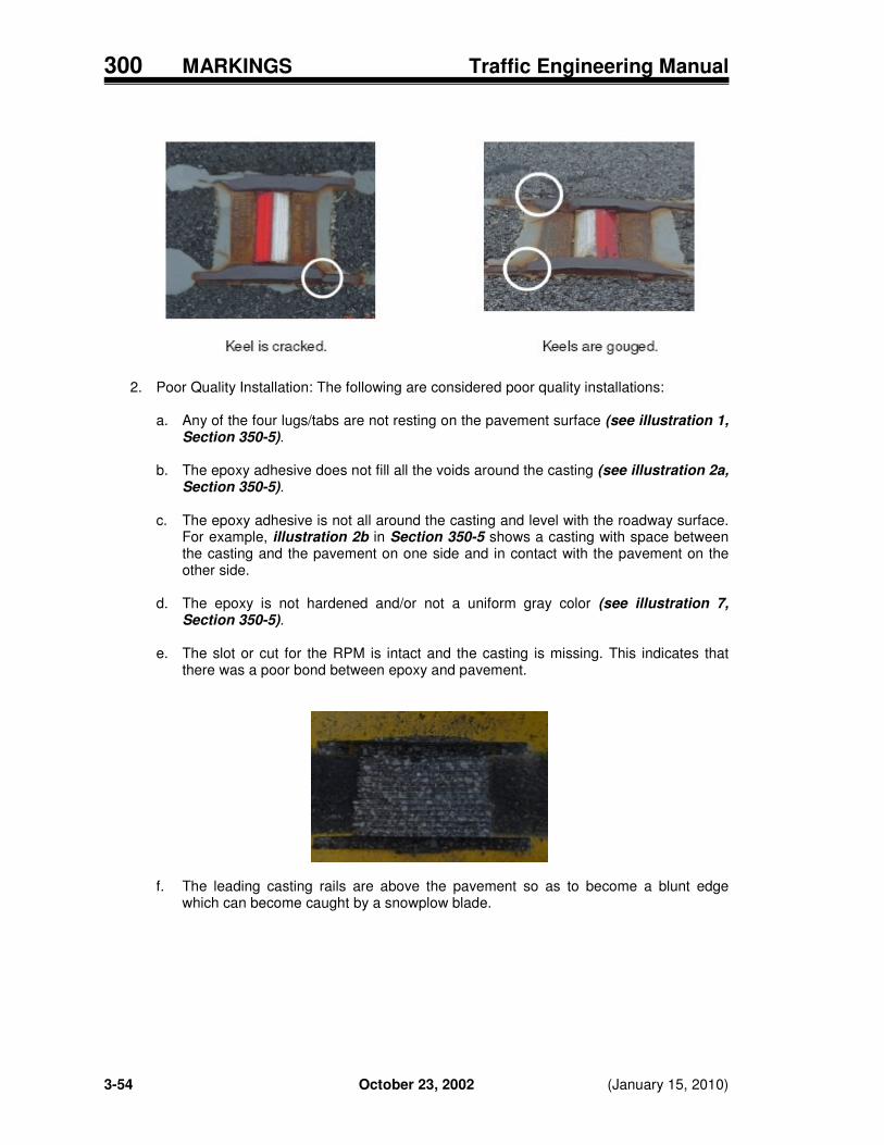
300 MARKINGS Traffic Engineering Manual
3-54 October 23, 2002 (January 15, 2010)
2. Poor Quality Installation: The following are considered poor quality installations:
a. Any of the four lugs/tabs are not resting on the pavement surface (see illustration 1, Section 350-5).
b. The epoxy adhesive does not fill all the voids around the casting (see illustration 2a,
Section 350-5). c. The epoxy adhesive is not all around the casting and level with the roadway surface.
For example, illustration 2b in Section 350-5 shows a casting with space between the casting and the pavement on one side and in contact with the pavement on the other side.
d. The epoxy is not hardened and/or not a uniform gray color (see illustration 7,
Section 350-5).
e. The slot or cut for the RPM is intact and the casting is missing. This indicates that there was a poor bond between epoxy and pavement.
f. The leading casting rails are above the pavement so as to become a blunt edge which can become caught by a snowplow blade.
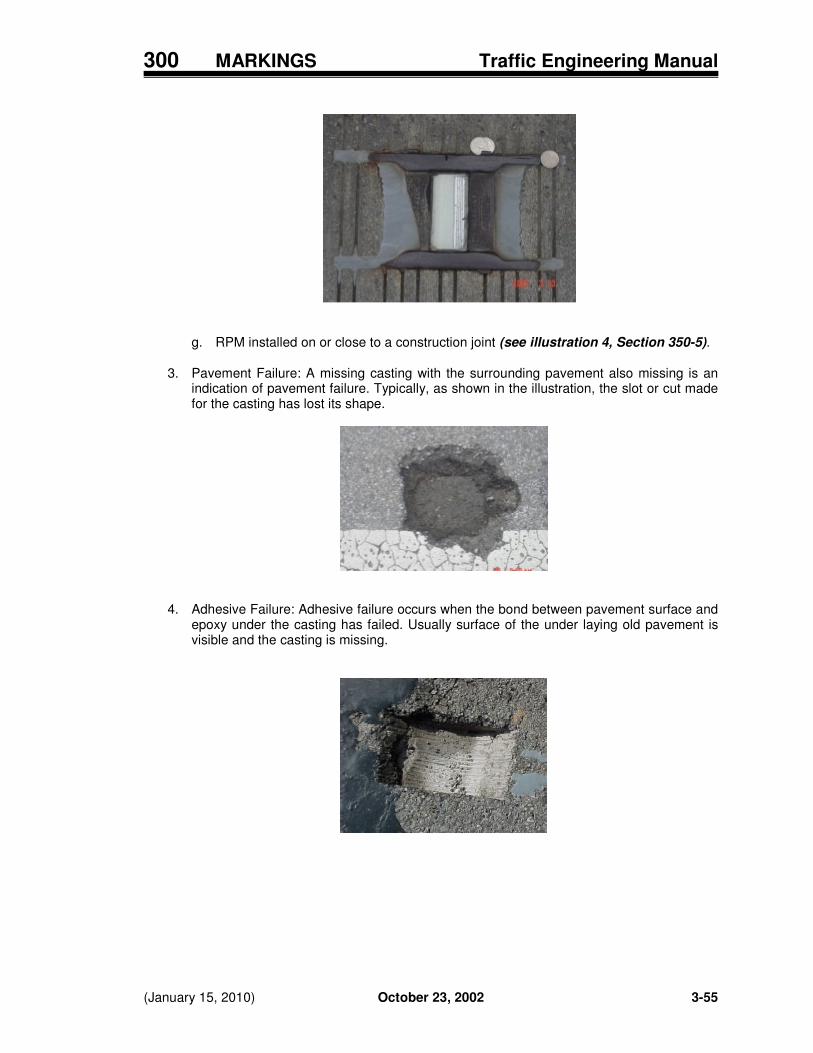
300 MARKINGS Traffic Engineering Manual
(January 15, 2010) October 23, 2002 3-55
g. RPM installed on or close to a construction joint (see illustration 4, Section 350-5).
3. Pavement Failure: A missing casting with the surrounding pavement also missing is an indication of pavement failure. Typically, as shown in the illustration, the slot or cut made for the casting has lost its shape.
4. Adhesive Failure: Adhesive failure occurs when the bond between pavement surface and
epoxy under the casting has failed. Usually surface of the under laying old pavement is visible and the casting is missing.

300 MARKINGS Traffic Engineering Manual
3-56 October 23, 2002 (January 15, 2010)
Intentionally blank.

300 MARKINGS Traffic Engineering Manual
(January 15, 2010) October 23, 2002 3-57
370 OTHER CONSIDERATIONS
This Chapter has been reserved for information regarding other considerations related to traffic control markings. 380 RESEARCH
This Chapter has been reserved for information about pertinent research regarding traffic control markings. 395 REFERENCE RESOURCES
Various reference resources that may be useful have been noted in Sections 193, 194 and 195.

300 MARKINGS Traffic Engineering Manual
3-58 October 23, 2002 (January 15, 2010)
Intentionally blank.

300 MARKINGS Traffic Engineering Manual
(January 15, 2010) October 23, 2002 3-59
396 FORMS INDEX
396-1 Air Speed Check Zone Request Form As noted in Section 301-10, the Form 396-1 should be used when requesting a new or revised Air Speed Check Zone. The same form is used to abolish an Air Speed Check Zone. A copy of the form is available on-line at the OTE forms web page: www.dot.state.oh.us/Divisions/HighwayOps/Traffic/Pages/Forms.aspx

300 MARKINGS Traffic Engineering Manual
3-60 October 23, 2002 (January 15, 2010)
Intentionally blank.
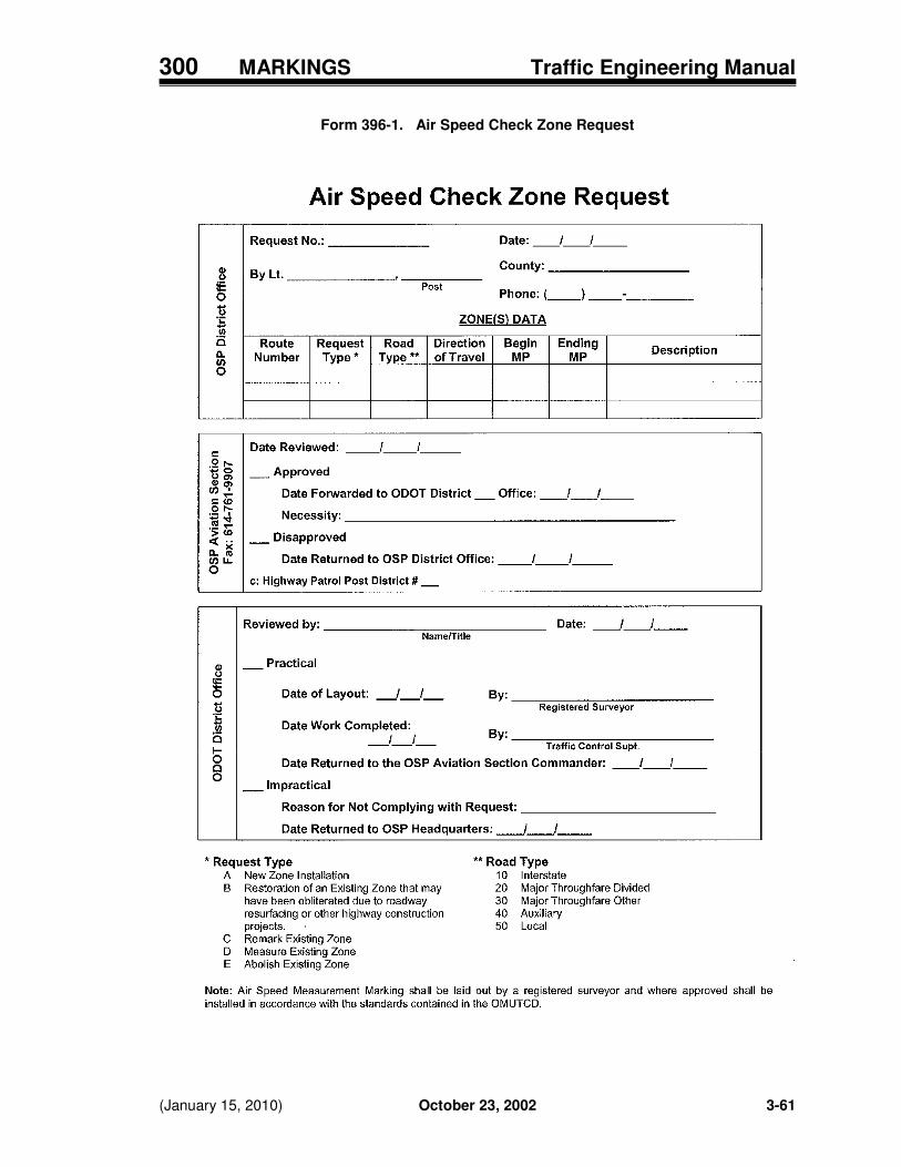
300 MARKINGS Traffic Engineering Manual
(January 15, 2010) October 23, 2002 3-61
Form 396-1. Air Speed Check Zone Request

300 MARKINGS Traffic Engineering Manual
3-62 October 23, 2002 (January 15, 2010)
Intentionally blank.

300 MARKINGS Traffic Engineering Manual
(January 15, 2010) October 23, 2002 3-63
397 TABLES INDEX
397-1 Material Selection for Pavement Marking and Expected Marking Life in Years As noted in Section 301-2, Table 397-1 is used to determine the appropriate type of pavement marking material to use. 397-2 Area Calculations for Words and Symbols As noted in Section 301-8, to help in calculating materials quantities, Table 397-2 provides information on the area for various auxiliary pavement markings. 397-3 Rating Daytime Color of Long Line Pavement Marking As noted in Section 350-2, when conducting the performance evaluation described in CMS Item 614.11 the ratings given in Table 397-3 shall be used. 397-4 Night Visibility Rating for Long Line Pavement Marking As noted in Section 350-2, when conducting the performance evaluation described in CMS Item 614.11 the ratings given in Table 397-4 shall be used. 397-5 Durability Rating for Long Line Pavement Marking As noted in Section 350-2, when conducting the performance evaluation described in CMS Item 614.11 the ratings given in Table 397-54 shall be used.

300 MARKINGS Traffic Engineering Manual
3-64 October 23, 2002 (January 15, 2010)
Intentionally blank.

300 MARKINGS Traffic Engineering Manual
(January 15, 2010) October 23, 2002 3-65
Table 397-1. Material Selection for Pavement Marking and Expected Marking Life** in Years
a. Long Line Pavement Marking ���� 2 Lane or General System (See next page for related notes.)
Remaining Pavement Surface Life *
Asphalt
Concrete
ADT < 5,000
Type Years
ADT > 5,000
Type Years
ADT < 5,000
Type Years
ADT > 5,000
Type Years
0 - 2 years Water-Based Paint
1
Polyester Spray Thermo Water-Based Paint
2 2 1
Polyester Water-Based Paint
2 1
Polyester Spray Thermo Water-Based Paint
2 2 1
3 - 4 years
Polyester Spray Thermo Water-Based Paint
3 2 1
Polyester Spray Thermo Water-Based Paint
2 2 1
Spray Thermo Water-Based Paint
2 1
Epoxy Spray Thermo Water-Based Paint
4 2 1
> 4 years
Thermo Polyester
4 3
Epoxy Thermo Polyester Spray Thermo
4 4 2 2
Epoxy Spray Thermo Water-Based Paint
4 2 1
Epoxy
4
New Surface i) <40� F ii) 40 to 50� F iii) > 50� F
Alkyd Paint Water-Based Paint Thermo
1 1 4
Alkyd Paint Water-Based Paint Thermo
1 1 4
Alkyd Paint Water-Based Paint Epoxy
1 1 4
Alkyd Paint Water-Based Paint Epoxy
1 1 4
b. Long Line Pavement Marking ���� Multilane or Priority System (See next page for related notes.)
Remaining Pavement Surface Life *
Asphalt
Concrete
ADT < 5,000 Type
Years
ADT > 5,000
Type Years
ADT < 5,000
Type Years
ADT > 5,000
Type Years
0 - 2 years Polyester Water-Based Paint
2 1
Polyester Spray Thermo Water-Based Paint
2 2 1
Polyester Water-Based Paint
2 1
Polyester Spray Thermo Water-Based Paint
2 2 1
3 - 4 years
Polyester Spray Thermo Water-Based Paint
3 2 1
Polyester Spray Thermo Water-Based Paint
2 2 1
Polyester Spray Thermo Water-Based Paint
2 2 1
Epoxy Spray Thermo
4 2
> 4 years
Thermo Polyester Spray Thermo Water-Based Paint
4 3 2 1
Epoxy Thermo Polyester
4 4 2
Epoxy Spray Thermo
4 2
Epoxy
4
New Surface i) <40� F ii) 40 to 50� F iii) > 50� F
Alkyd Paint Water-Based Paint Thermo
1 1 4
Alkyd Paint Water-Based Paint Thermo
1 1 4
Alkyd Paint Water-Based Paint Epoxy
1 1 4
Alkyd Paint Water-Based Paint Epoxy
1 1 4

300 MARKINGS Traffic Engineering Manual
3-66 October 23, 2002 (January 15, 2010)
Table 397-1. Material Selection for Pavement Marking and Expected Marking Life in Years (continued)
c. Auxiliary Pavement Marking ���� 2-Lane and Multilane or Priority System Remaining Pavement Surface Life *
Asphalt
Concrete
ADT < 5,000
Type Years
ADT > 5,000
Type Years
ADT < 5,000
Type Years
ADT > 5,000
Type Years
0 - 2 years Water-Based Paint
1
Water-Based Paint
1
Spray Thermoplastic Alkyd Paint Water-Based Paint
2 1 1
Heat Fused Preformed Tape Spray Thermoplastic Alkyd Paint Water-Based Paint
2 2 1 1
3 - 4 years
Heat Fused Pre-formed Tape Polyester
4 1-2
Heat Fused Pre-formed
Tape
2
Heat Fused Pre-formed Tape Thermoplastic Spray Thermoplastic Water-Based Paint
3 2 2 1
Heat Fused Preformed
Tape
2
> 4 years
Heat Fused Pre-formed Tape Polyester Water-Based Paint
4 1-2 1
Heat Fused Pre-formed Tape
2
Heat Fused Pre-formed Tape Thermoplastic Spray Thermoplastic
3 2 2
Heat Fused Preformed Tape
2
New Surface i) <40� F ii) 40 to 50� F iii) > 50� F
Same as used for long lines
Same as used for long lines
Same as used for long lines
Same as used for long lines
Notes: * Remaining pavement surface life is the life before resurfacing, reconstruction or before crack sealant
will cover the pavement markings. ** The expected life of edge line pavement marking is typically 20 to 30 percent longer as compared to
center line and lane line pavement markings expected life as shown in this table. 1. Spray thermoplastic works well for retracing existing thermoplastic. For other materials, check with
material suppliers. 2. Auxiliary markings not regularly run over by traffic will last 1.5 to 2 times longer. 3. Surface preparation may be required to remove old markings as recommended by supplier. 4. Remove curing compound completely from new concrete surfaces - follow CMS Item 641.05. 5. Polyester pavement marking material is addressed in CMS Item 643. Since it adheres best to a worn
surface, polyester is not to be placed until new asphalt pavement has been open to traffic at least fourteen days. Polyester pavement marking material shall only be used on CMS Item 446 or 448 pavements. This material shall not be used on the following asphalt concrete surfaces due to poor bonding qualities: open graded courses, slurry seal, Supplemental Specification (SS) 805 Rubberized Sand Asphalt, and SS 807 Latex Modified Emulsified Asphalt Pavement Course. Any Asphalt Concrete (Item Special) should be questioned before considering placement of polyester material on it.
6. Primer is required for thermoplastic when used on concrete. 7. Due to the high cost of preformed material, it should only be considered for use where extra long life is
needed or in certain applications, such as bridge decks where thermoplastic has not adhered well. 8. Epoxy should only be used on pavements in good condition after surface preparation has been
accomplished per manufacturer recommendations. 9. Thermoplastic and epoxy pavement marking materials are not recommended for striping long line
markings on routes with 2500 or less ADT since these materials must be removed before a chip seal coat can be applied to the pavement.

300 MARKINGS Traffic Engineering Manual
Revised January 20, 2012 October 23, 2002 3-67
Table 397-2. Area Calculations for Words and Symbols
WORDS
square feet
TYPE
HEIGHT
6 ft.
8 ft.
STOP
17
24
ONLY
17
23
SCHOOL
1
27
37
Handicap Symbol
Height in.
Width in
Area Square ft.
41 36 2.7
R X R SYMBOL
square feet 1
WIDTH (W)
2
8 ft. min.
9 ft.
10 ft.
11 ft.
12 ft.
67
68
70
71
72
Notes: 1. The area for transverse lines for the Railroad and SCHOOL Pavement Marking Symbols
varies with the width of the pavement; therefore, it must be added to the values in the above tables.
2. Width varies according to lane width, except that the “R” is 6 feet long.
LANE-USE ARROWS square feet
ARROW TYPE SIZE AREA
Turn Arrow 8.0 17
Straight Arrow 9.5 13
Combined Arrow 12.75 28
Lane-Reduction Arrow 18.0 46
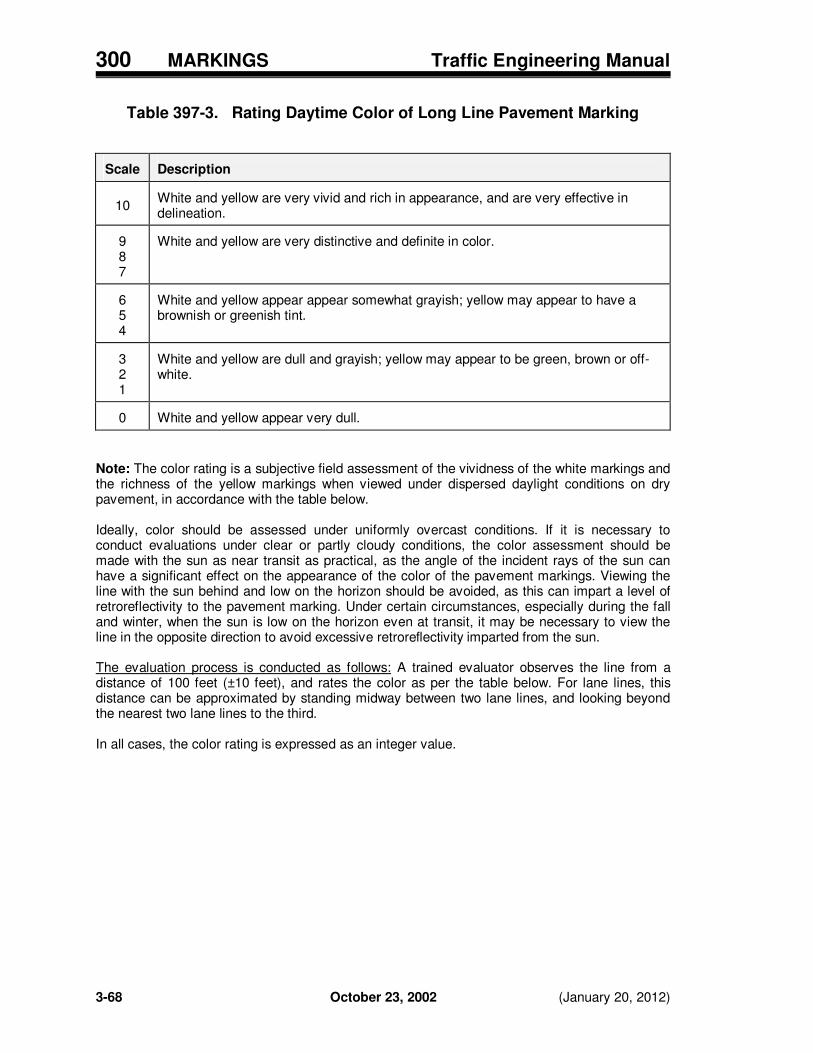
300 MARKINGS Traffic Engineering Manual
3-68 October 23, 2002 (January 20, 2012)
Table 397-3. Rating Daytime Color of Long Line Pavement Marking
Scale
Description
10
White and yellow are very vivid and rich in appearance, and are very effective in delineation.
9 8 7
White and yellow are very distinctive and definite in color.
6 5 4
White and yellow appear appear somewhat grayish; yellow may appear to have a brownish or greenish tint.
3 2 1
White and yellow are dull and grayish; yellow may appear to be green, brown or off-white.
0
White and yellow appear very dull.
Note: The color rating is a subjective field assessment of the vividness of the white markings and the richness of the yellow markings when viewed under dispersed daylight conditions on dry pavement, in accordance with the table below. Ideally, color should be assessed under uniformly overcast conditions. If it is necessary to conduct evaluations under clear or partly cloudy conditions, the color assessment should be made with the sun as near transit as practical, as the angle of the incident rays of the sun can have a significant effect on the appearance of the color of the pavement markings. Viewing the line with the sun behind and low on the horizon should be avoided, as this can impart a level of retroreflectivity to the pavement marking. Under certain circumstances, especially during the fall and winter, when the sun is low on the horizon even at transit, it may be necessary to view the line in the opposite direction to avoid excessive retroreflectivity imparted from the sun. The evaluation process is conducted as follows: A trained evaluator observes the line from a distance of 100 feet (±10 feet), and rates the color as per the table below. For lane lines, this distance can be approximated by standing midway between two lane lines, and looking beyond the nearest two lane lines to the third. In all cases, the color rating is expressed as an integer value.

300 MARKINGS Traffic Engineering Manual
(January 15, 2010) October 23, 2002 3-69
Table 397-4. Rating Night Visibility of Long Line Pavement Marking
Uniformity
Retroreflectivity
Nighttime Color
+4
Line is completely consistent in appearance, with no distinguishable variations
+3 Line is generally consistent in appearance, with minimal variations
+3 Line is very bright +3
White appears as very clean reflected light; yellow is distinctive and definite in color
+2
Line is generally consistent in appearance, but with distinctly brighter and darker areas
+2 Line is bright +2
White and yellow appear somewhat grayish; yellow may appear to have a brownish or greenish tint
+1
Line is inconsistent in appearance, with distinctly brighter and darker areas
+1 Line appears adequate, but with unimpressive brightness
+1
White and yellow are dull and grayish; yellow may appear to be green, brown or off-white
0 Line is very inconsistent in appearance and may appear blotchy
0
Line has minimal brightness; line is discernable but only marginally effective
0 White and yellow appear very dull
Note: Night visibility is a subjective rating based on the appearance of the pavement marking line on dry pavement to a trained evaluator in a vehicle when viewed under low beam headlight illumination at night. The night visibility rating consists of an evaluation of three distinct attributes: Uniformity – The ability of the line to provide a consistent, unvarying appearance along its length and across its width. Retroreflectivity – The brightness of the line in the return of incident illumination. Nighttime Color – The vividness of the white markings and the richness of the yellow markings when seen with retroreflected light. The rating scales for each of these attributes is described in the tables below. The evaluation process is conducted as follows: With appropriate traffic control in place, slowly drive through the test section at night with low beam headlights, and observe the test line. First, rate the uniformity of the line appearance. Second, rate the line retroreflectivity. Finally, rate the color. Add up the three individual scores to get a composite rating for the line. In all cases, the night visibility rating is expressed as an integer value.

300 MARKINGS Traffic Engineering Manual
3-70 October 23, 2002 (January 15, 2010)
Table 397-5. Durability of Long Line Pavement Marking
Durability Durability
Rating
Percentage of Line Remaining
Rating
Percentage of Line Remaining
10 100 4 40
9 90 3 30
8 80 2 20
7 70 1 10
6 60 0 0
5 50
Note: Durability is the rating of the adherence of the pavement marking material to the sound pavement surface, based on the percentage of the material remaining adhered. Durability is not an assessment of the thickness of the material or retention of optical elements, but rather an analysis of the amount of bare, sound pavement showing that was once covered with pavement marking material. Durability is an objective assessment, although there exists no mechanical means to reliably and quickly measure durability in the field. Therefore, the field assessment of pavement marking durability must be made by trained evaluators. The evaluation process is conducted as follows: Several trained evaluators observe the test line by viewing vertically from above. An assessment of the durability is made by each. The durability rating is agreed upon in the field by a consensus of the evaluators. If line deterioration is inconsistent throughout the length of the test section, several line segments should be evaluated. Each segment should be a minimum of ten feet in length, and no less than 2% of the total length of the line. The durability rating is the lowest rating for any line segment, as agreed upon by a consensus of the evaluators. Portions of the line subjected to unusual wear, such as at driveways or from line tracking prior to final curing, should be categorically excluded from the durability assessment. In addition, failures within the pavement must be recognized and discounted when assessing the durability of the pavement marking. In all cases, the durability rating is expressed as an integer value.

300 MARKINGS Traffic Engineering Manual
Revised July 20, 2012 October 23, 2002 3-71
398 FIGURES INDEX
398-1 Standard Delineation for Median Opening for Private Access As noted in Section 304-4, Figure 398-1 provides detail guidelines in marking a median opening for private drive access. 398-2 Marking a Narrow or One-Lane Bridge As noted in Sections 202-5, 202-14.2, 302-6 and 304-5, Figure 398-2 provides detail guidelines marking of a narrow or one-lane bridge. 398-3 Standard Delineation for Parallel Left-Turn Lane As noted in Sections 202-14.3 and 304-6, Figure 398-3 provides detail guidelines for marking a parallel left-turn lane. 398-4 Standard Delineation for Tapered Left-Turn Lane As noted in Sections 202-14.3 and 304-6, Figure 398-4 provides detail guidelines for marking a tapered left-turn lane.

300 MARKINGS Traffic Engineering Manual
3-72 October 23, 2002 (July 20, 2012)
Intentionally blank.

300 MARKINGS Traffic Engineering Manual
Revised July 20, 2012 October 23, 2002 3-73
Figure 398-1. Standard Delineation for Median Opening for Private Access
Note: If the median width exceeds 40 feet, the delineator at the median nose should be erected 20 ft from the pavement edge.

300 MARKINGS Traffic Engineering Manual
3-74 October 23, 2002 Revised July 20, 2012
Figure 398-2. Marking a Narrow or One-Lane Bridge
Note: Center line should stop 150 feet before a one-lane bridge, but may be continued across a narrow bridge (see OMUTCD Section 3B.01).

300 MARKINGS Traffic Engineering Manual
Revised July 20, 2012 October 23, 2002 3-75
Figure 398-3. Standard Delineation for Parallel Left-Turn Lane
Note: This figure is intended to show standard delineation only - not all necessary pavement markings and signing are shown.

300 MARKINGS Traffic Engineering Manual
3-76 October 23, 2002 Revised July 20, 2012
Figure 398-4. Standard Delineation for Tapered Left-Turn Lane
Note: This figure is intended to show standard delineation only - not all necessary pavement markings and signing are shown.