mars atmospheric in situ resource utilization projects … · mars atmospheric in situ resource...
TRANSCRIPT
Mars Atmospheric In Situ Resource Utilization Projects
at the Kennedy Space Center
Anthony Muscatello, Paul Hintze, Anne Meier, Jon Bayliss, Laurel Karr, Steve Paley, Matt Marone, Tracy Gibson, Jan Surma, Matt Mansell, Griffin
Lunn, Robert Devor, and Mark Berggren
NASA – Kennedy Space Center
Earth & Space 2016
Orlando, FL
April 12-15, 2016
1
https://ntrs.nasa.gov/search.jsp?R=20160005057 2018-07-08T15:40:13+00:00Z
• Projects and Team Members
• Martian Resources
• Mars Atmospheric Processing Module
• Mars Propellant Production with Ionic Liquids
• Self-Cleaning Boudouard Reactor for Full Oxygen Recovery
• Conclusions
Outline
2
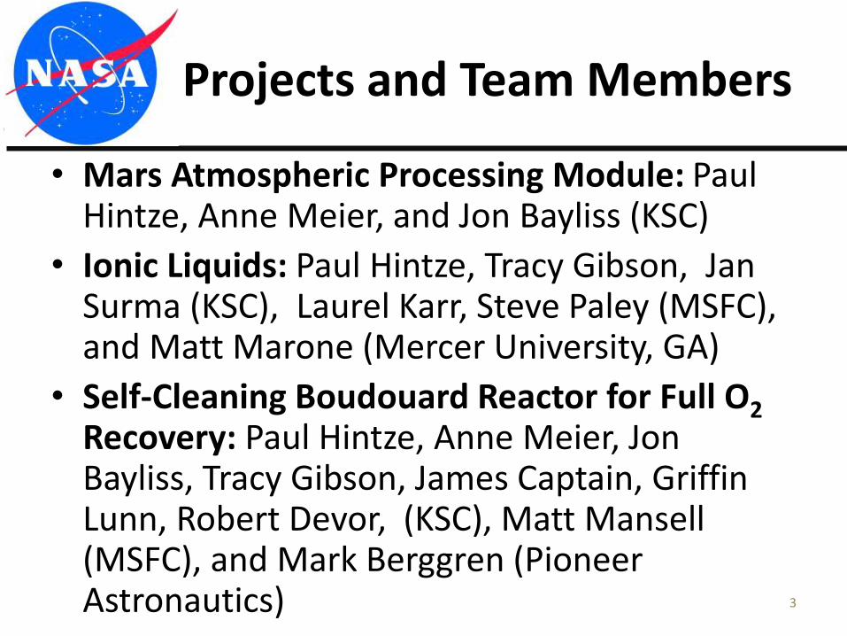
• Mars Atmospheric Processing Module: Paul Hintze, Anne Meier, and Jon Bayliss (KSC)
• Ionic Liquids: Paul Hintze, Tracy Gibson, Jan Surma (KSC), Laurel Karr, Steve Paley (MSFC), and Matt Marone (Mercer University, GA)
• Self-Cleaning Boudouard Reactor for Full O2Recovery: Paul Hintze, Anne Meier, Jon Bayliss, Tracy Gibson, James Captain, Griffin Lunn, Robert Devor, (KSC), Matt Mansell (MSFC), and Mark Berggren (Pioneer Astronautics)
Projects and Team Members
3
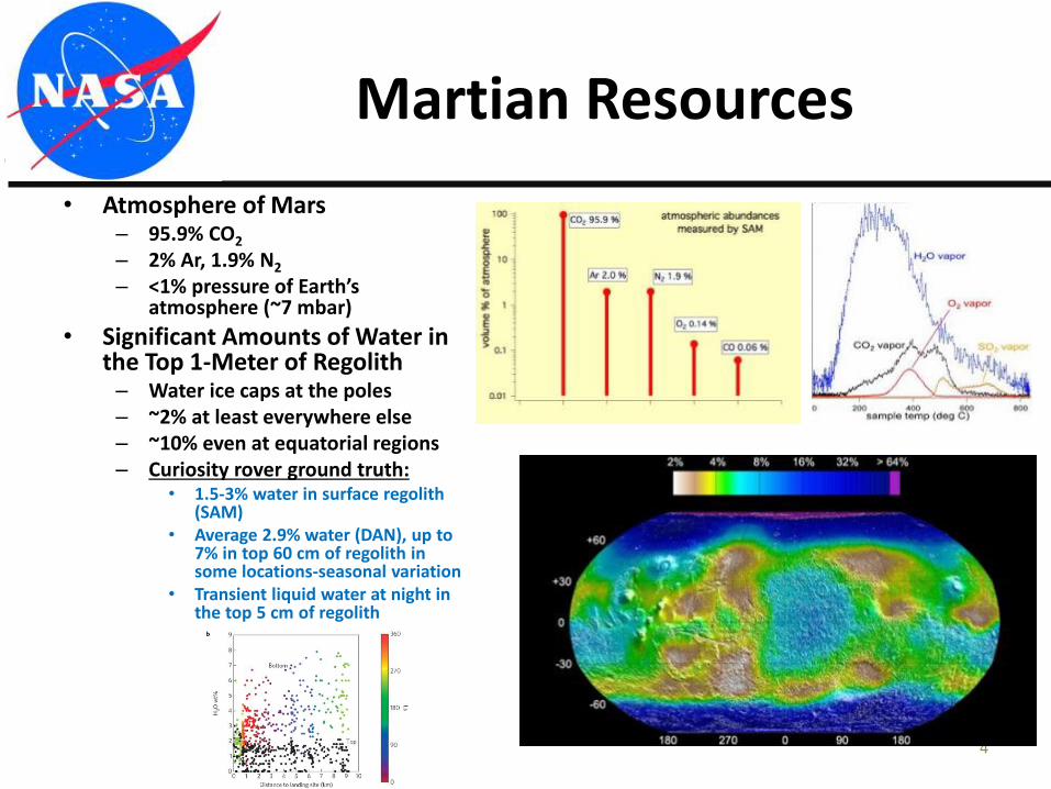
• Atmosphere of Mars– 95.9% CO2
– 2% Ar, 1.9% N2
– <1% pressure of Earth’s atmosphere (~7 mbar)
• Significant Amounts of Water in the Top 1-Meter of Regolith– Water ice caps at the poles– ~2% at least everywhere else– ~10% even at equatorial regions– Curiosity rover ground truth:
• 1.5-3% water in surface regolith (SAM)
• Average 2.9% water (DAN), up to 7% in top 60 cm of regolith in some locations-seasonal variation
• Transient liquid water at night in the top 5 cm of regolith
Martian Resources
4
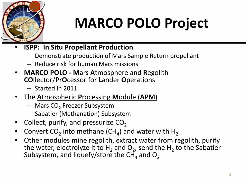
• ISPP: In Situ Propellant Production– Demonstrate production of Mars Sample Return propellant– Reduce risk for human Mars missions
• MARCO POLO - Mars Atmosphere and Regolith COllector/PrOcessor for Lander Operations – Started in 2011
• The Atmospheric Processing Module (APM)– Mars CO2 Freezer Subsystem– Sabatier (Methanation) Subsystem
• Collect, purify, and pressurize CO2
• Convert CO2 into methane (CH4) and water with H2
• Other modules mine regolith, extract water from regolith, purify the water, electrolyze it to H2 and O2, send the H2 to the Sabatier Subsystem, and liquefy/store the CH4 and O2
MARCO POLO Project
5
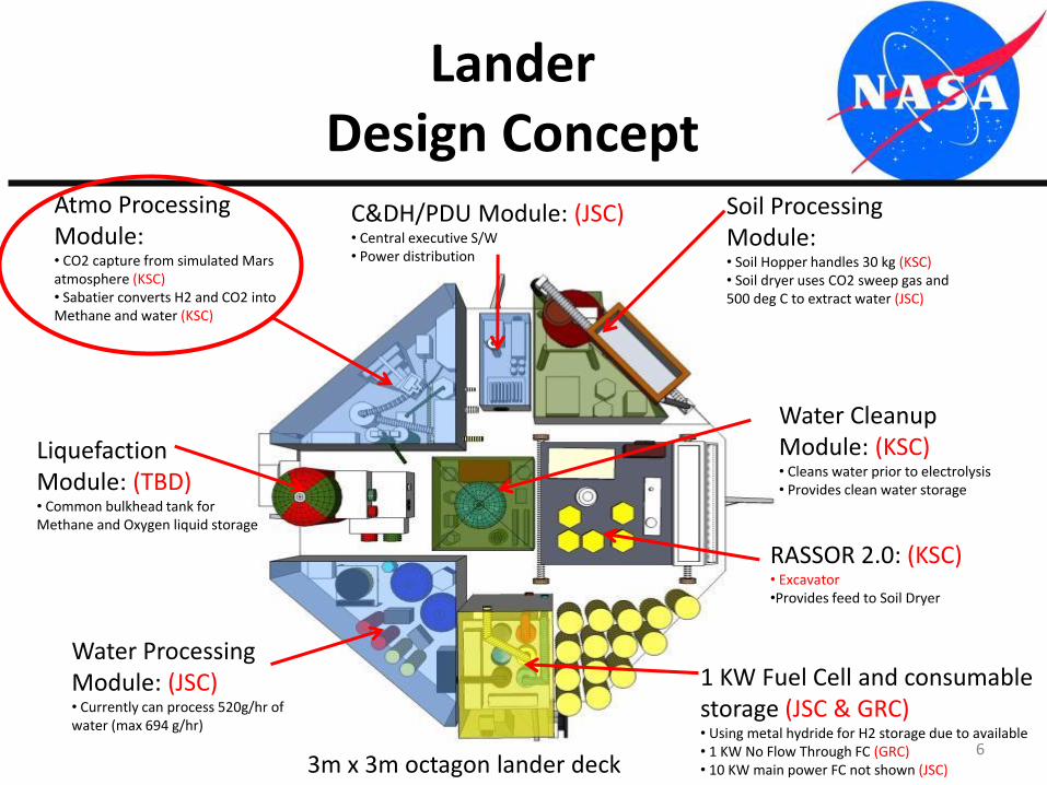
LanderDesign Concept
Atmo Processing Module:• CO2 capture from simulated Mars atmosphere (KSC)• Sabatier converts H2 and CO2 into Methane and water (KSC)
Water Processing Module: (JSC)• Currently can process 520g/hr of water (max 694 g/hr)
1 KW Fuel Cell and consumable storage (JSC & GRC)• Using metal hydride for H2 storage due to available• 1 KW No Flow Through FC (GRC)• 10 KW main power FC not shown (JSC)
Liquefaction Module: (TBD)• Common bulkhead tank for Methane and Oxygen liquid storage
Soil Processing Module:• Soil Hopper handles 30 kg (KSC)• Soil dryer uses CO2 sweep gas and 500 deg C to extract water (JSC)
C&DH/PDU Module: (JSC)• Central executive S/W• Power distribution
Water Cleanup Module: (KSC)• Cleans water prior to electrolysis• Provides clean water storage
RASSOR 2.0: (KSC)• Excavator•Provides feed to Soil Dryer
3m x 3m octagon lander deck6
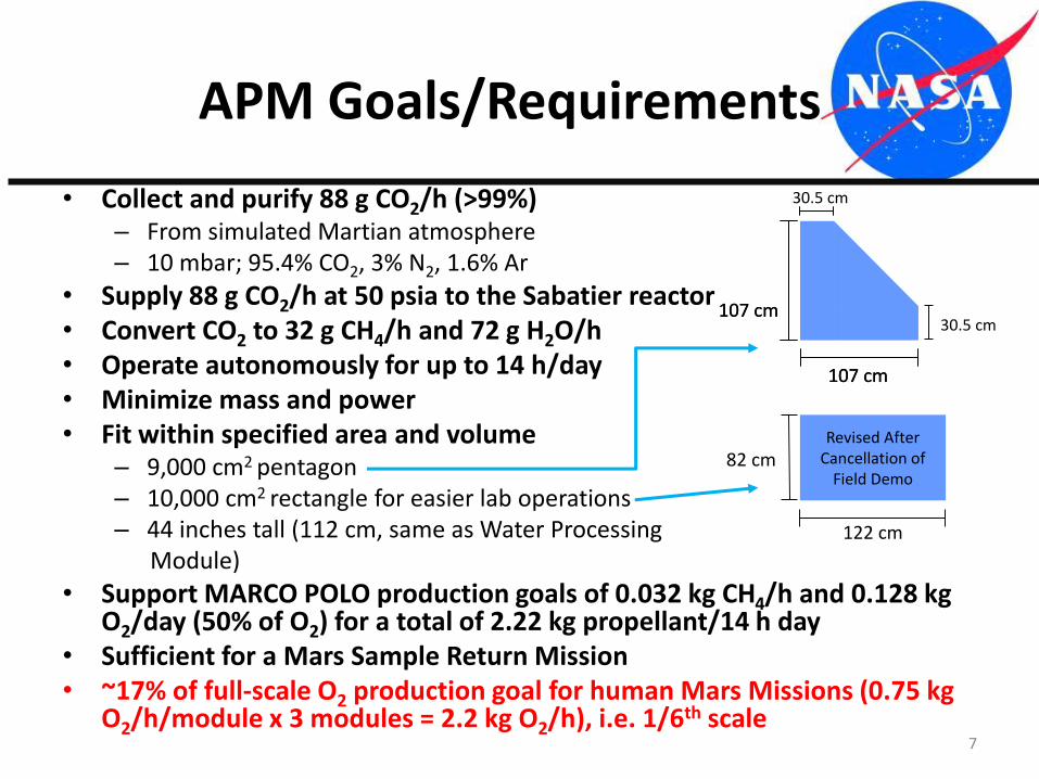
• Collect and purify 88 g CO2/h (>99%)– From simulated Martian atmosphere – 10 mbar; 95.4% CO2, 3% N2, 1.6% Ar
• Supply 88 g CO2/h at 50 psia to the Sabatier reactor• Convert CO2 to 32 g CH4/h and 72 g H2O/h• Operate autonomously for up to 14 h/day• Minimize mass and power• Fit within specified area and volume
– 9,000 cm2 pentagon– 10,000 cm2 rectangle for easier lab operations– 44 inches tall (112 cm, same as Water Processing
Module)
• Support MARCO POLO production goals of 0.032 kg CH4/h and 0.128 kg O2/day (50% of O2) for a total of 2.22 kg propellant/14 h day
• Sufficient for a Mars Sample Return Mission• ~17% of full-scale O2 production goal for human Mars Missions (0.75 kg
O2/h/module x 3 modules = 2.2 kg O2/h), i.e. 1/6th scale
APM Goals/Requirements
107 cm
107 cm
30.5 cm
30.5 cm107 cm
107 cm
7
82 cm
122 cm
Revised After Cancellation of
Field Demo
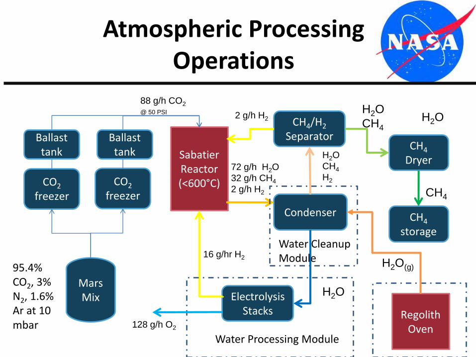
Atmospheric Processing Operations
Mars Mix
CO2
freezer
Sabatier Reactor(<600°C)
Condenser
CH4/H2
SeparatorCH4
Dryer
CH4
storage
88 g/h CO2
@ 50 PSI
95.4% CO2, 3% N2, 1.6% Ar at 10 mbar
72 g/h H2O
32 g/h CH4
2 g/h H2
H2O
CH4
H2
H2O
16 g/hr H2
H2O
CH4
CH4
H2O
Electrolysis Stacks
CO2
freezer
2 g/h H2
Water Processing Module
Water Cleanup Module
Ballast tank
Ballast tank
8
128 g/h O2
Regolith Oven
H2O(g)
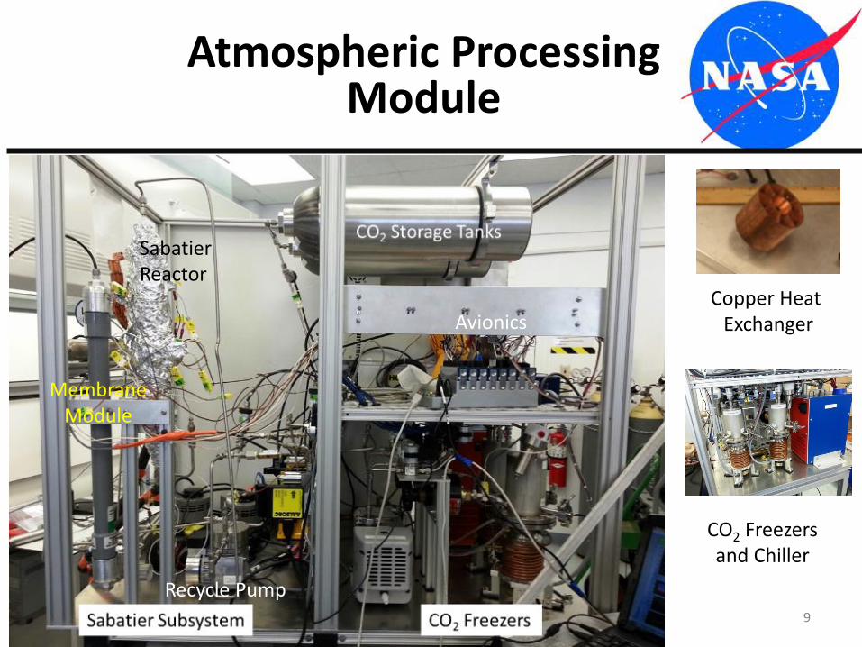
Atmospheric Processing Module
9
Copper Heat Exchanger
Recycle Pump
MembraneModule
CO2 Freezers and Chiller
Avionics
Sabatier Reactor
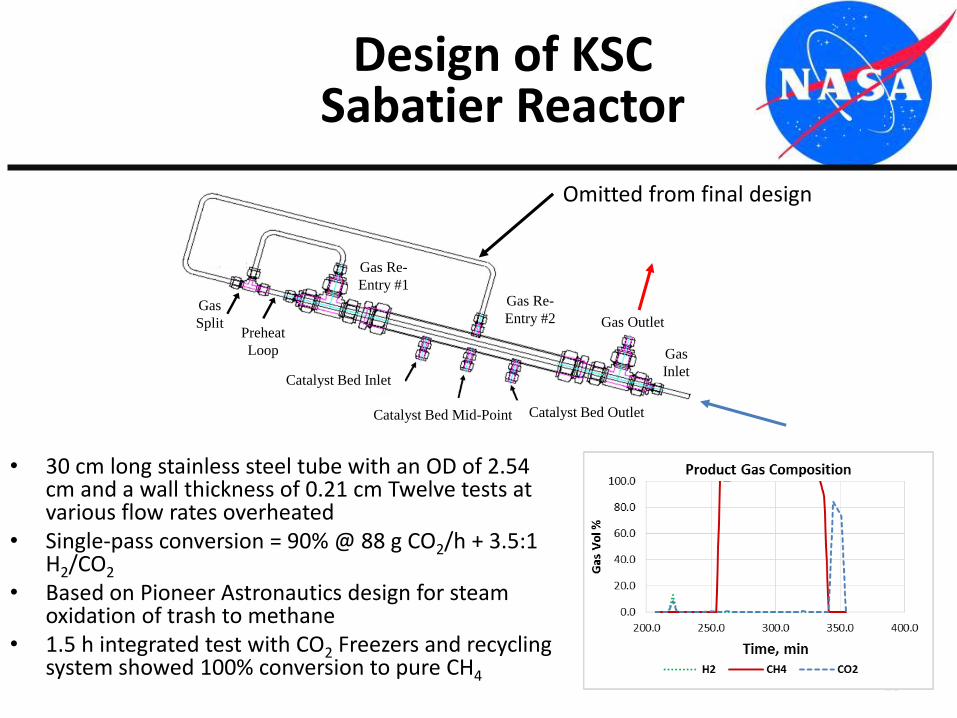
Design of KSC Sabatier Reactor
10
• 30 cm long stainless steel tube with an OD of 2.54 cm and a wall thickness of 0.21 cm Twelve tests at various flow rates overheated
• Single-pass conversion = 90% @ 88 g CO2/h + 3.5:1 H2/CO2
• Based on Pioneer Astronautics design for steam oxidation of trash to methane
• 1.5 h integrated test with CO2 Freezers and recycling system showed 100% conversion to pure CH4
Preheat
Loop
Gas
Split
Gas Re-
Entry #1Gas Re-
Entry #2
Catalyst Bed Inlet
Catalyst Bed Outlet
Gas Outlet
Gas
Inlet
Catalyst Bed Mid-Point
Omitted from final design
11
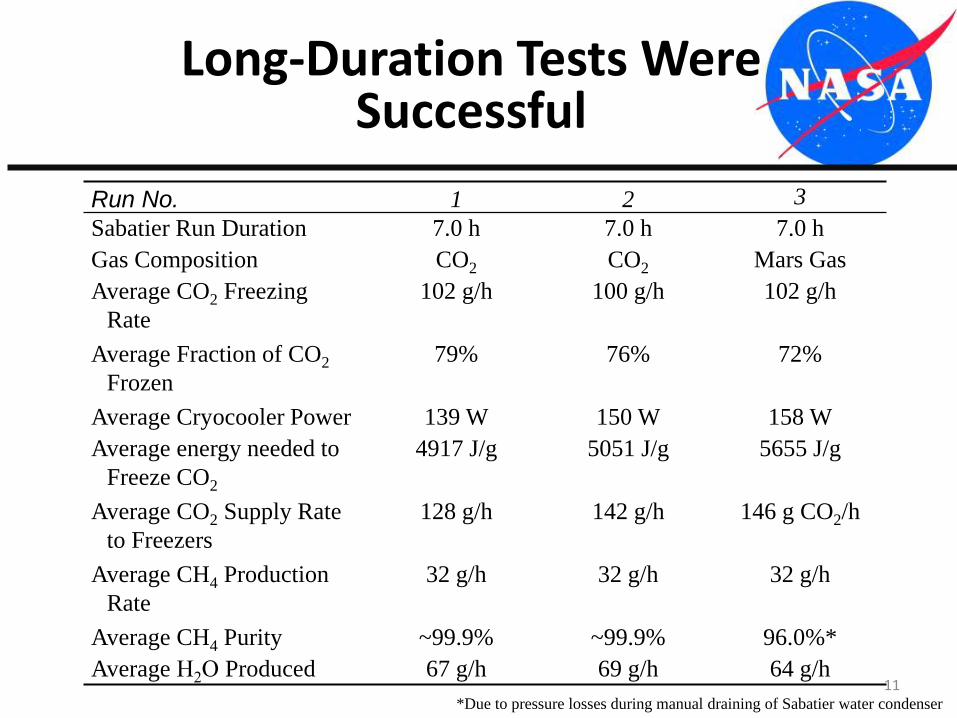
Long-Duration Tests Were Successful
Run No. 1 2 3
Sabatier Run Duration 7.0 h 7.0 h 7.0 h
Gas Composition CO2 CO2 Mars Gas
Average CO2 Freezing
Rate
102 g/h 100 g/h 102 g/h
Average Fraction of CO2
Frozen
79% 76% 72%
Average Cryocooler Power 139 W 150 W 158 W
Average energy needed to
Freeze CO2
4917 J/g 5051 J/g 5655 J/g
Average CO2 Supply Rate
to Freezers
128 g/h 142 g/h 146 g CO2/h
Average CH4 Production
Rate
32 g/h 32 g/h 32 g/h
Average CH4 Purity ~99.9% ~99.9% 96.0%*
Average H2O Produced 67 g/h 69 g/h 64 g/h
*Due to pressure losses during manual draining of Sabatier water condenser
12
0
50
100
150
200
250
300
350
400
450
500
0
50
100
150
200
250
300
350
0 100 200 300 400 500 600P
ow
er,
W
Tem
pe
ratu
re, K
Time, min
Cryocooler Temperature and Power
Cryocooler#1 Temp, K
Cryocooler#2 Temp, K
Cryocooler#1 Power,W
Crycooler#2 Power,W
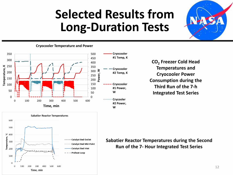
Selected Results from Long-Duration Tests
CO2 Freezer Cold Head Temperatures and Cryocooler Power
Consumption during the Third Run of the 7-h
Integrated Test Series
Sabatier Reactor Temperatures during the Second Run of the 7- Hour Integrated Test Series
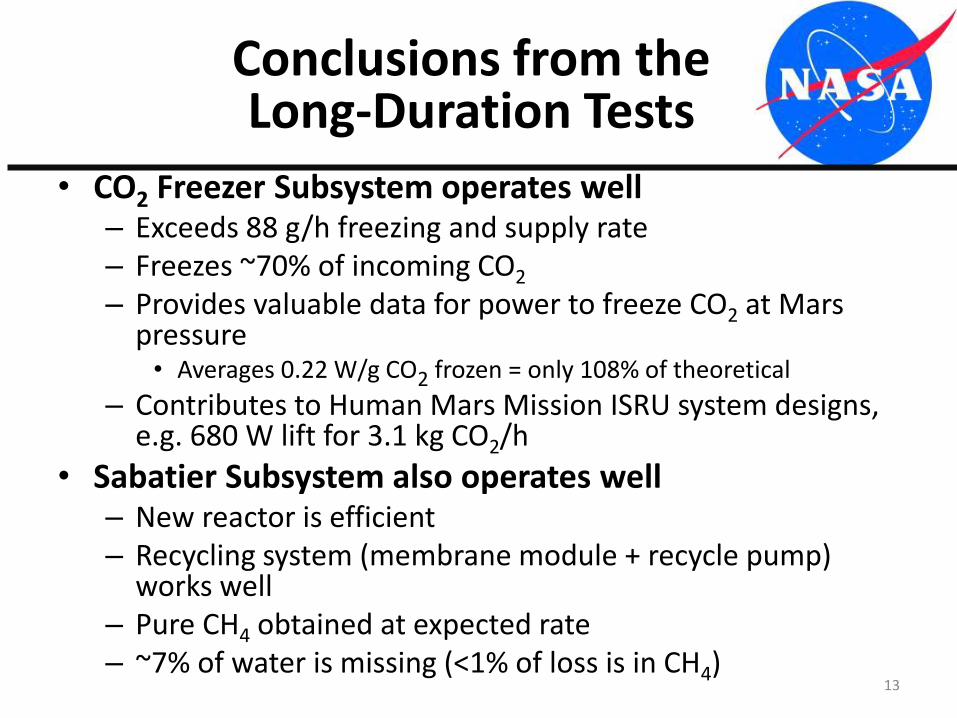
• CO2 Freezer Subsystem operates well– Exceeds 88 g/h freezing and supply rate– Freezes ~70% of incoming CO2
– Provides valuable data for power to freeze CO2 at Mars pressure• Averages 0.22 W/g CO2 frozen = only 108% of theoretical
– Contributes to Human Mars Mission ISRU system designs, e.g. 680 W lift for 3.1 kg CO2/h
• Sabatier Subsystem also operates well– New reactor is efficient– Recycling system (membrane module + recycle pump)
works well– Pure CH4 obtained at expected rate– ~7% of water is missing (<1% of loss is in CH4)
Conclusions from the Long-Duration Tests
13
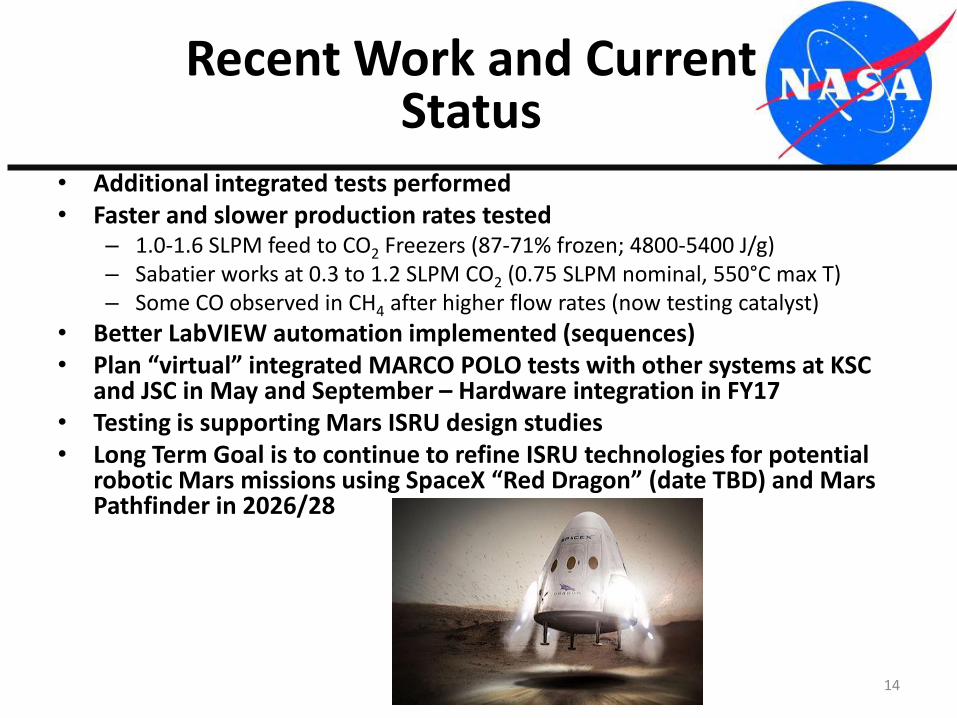
• Additional integrated tests performed• Faster and slower production rates tested
– 1.0-1.6 SLPM feed to CO2 Freezers (87-71% frozen; 4800-5400 J/g)– Sabatier works at 0.3 to 1.2 SLPM CO2 (0.75 SLPM nominal, 550°C max T)– Some CO observed in CH4 after higher flow rates (now testing catalyst)
• Better LabVIEW automation implemented (sequences)• Plan “virtual” integrated MARCO POLO tests with other systems at KSC
and JSC in May and September – Hardware integration in FY17• Testing is supporting Mars ISRU design studies• Long Term Goal is to continue to refine ISRU technologies for potential
robotic Mars missions using SpaceX “Red Dragon” (date TBD) and Mars Pathfinder in 2026/28
Recent Work and Current Status
14
Introduction – Ionic Liquids
15
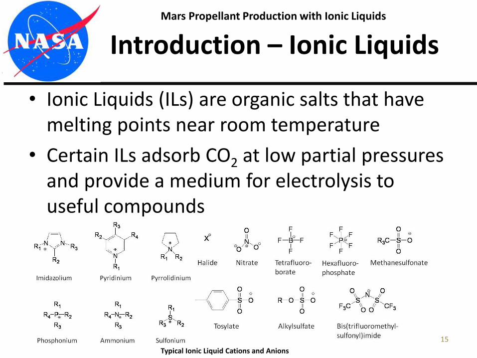
• Ionic Liquids (ILs) are organic salts that have melting points near room temperature
• Certain ILs adsorb CO2 at low partial pressures and provide a medium for electrolysis to useful compounds
Typical Ionic Liquid Cations and Anions
Mars Propellant Production with Ionic Liquids
Potential Benefits for ISRU
16
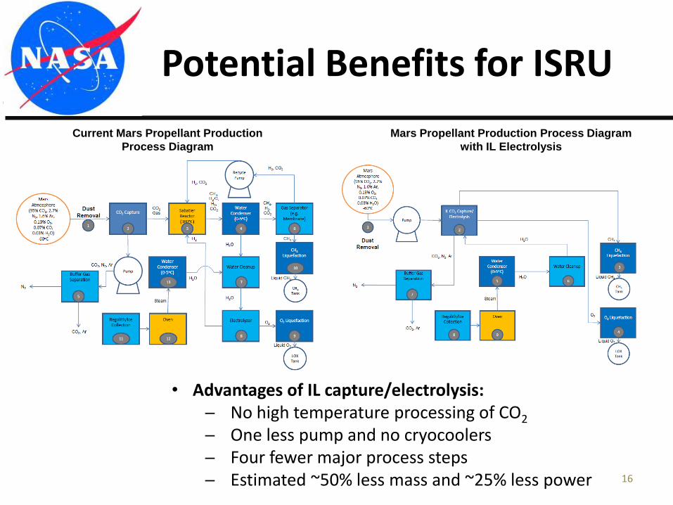
Current Mars Propellant Production
Process Diagram
Mars Propellant Production Process Diagram
with IL Electrolysis
• Advantages of IL capture/electrolysis:─ No high temperature processing of CO2
─ One less pump and no cryocoolers─ Four fewer major process steps─ Estimated ~50% less mass and ~25% less power
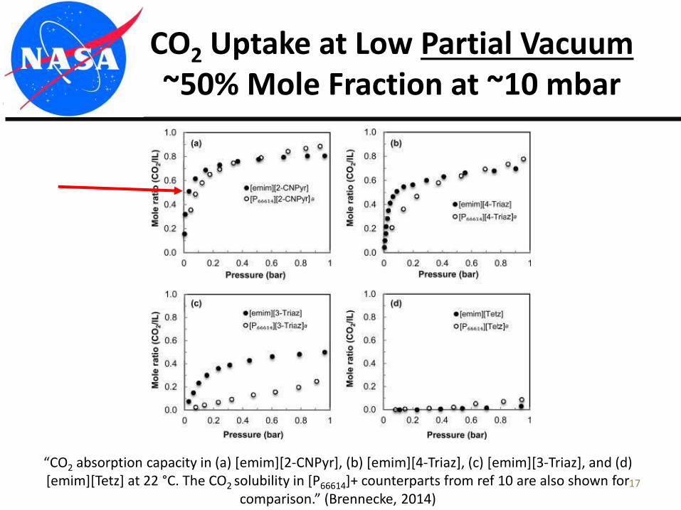
CO2 Uptake at Low Partial Vacuum ~50% Mole Fraction at ~10 mbar
17
“CO2 absorption capacity in (a) [emim][2-CNPyr], (b) [emim][4-Triaz], (c) [emim][3-Triaz], and (d) [emim][Tetz] at 22 °C. The CO2 solubility in [P66614]+ counterparts from ref 10 are also shown for
comparison.” (Brennecke, 2014)
18
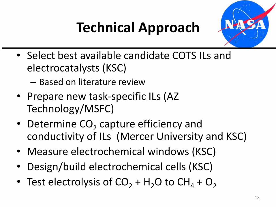
Technical Approach
• Select best available candidate COTS ILs and electrocatalysts (KSC)– Based on literature review
• Prepare new task-specific ILs (AZ Technology/MSFC)
• Determine CO2 capture efficiency and conductivity of ILs (Mercer University and KSC)
• Measure electrochemical windows (KSC)
• Design/build electrochemical cells (KSC)
• Test electrolysis of CO2 + H2O to CH4 + O2
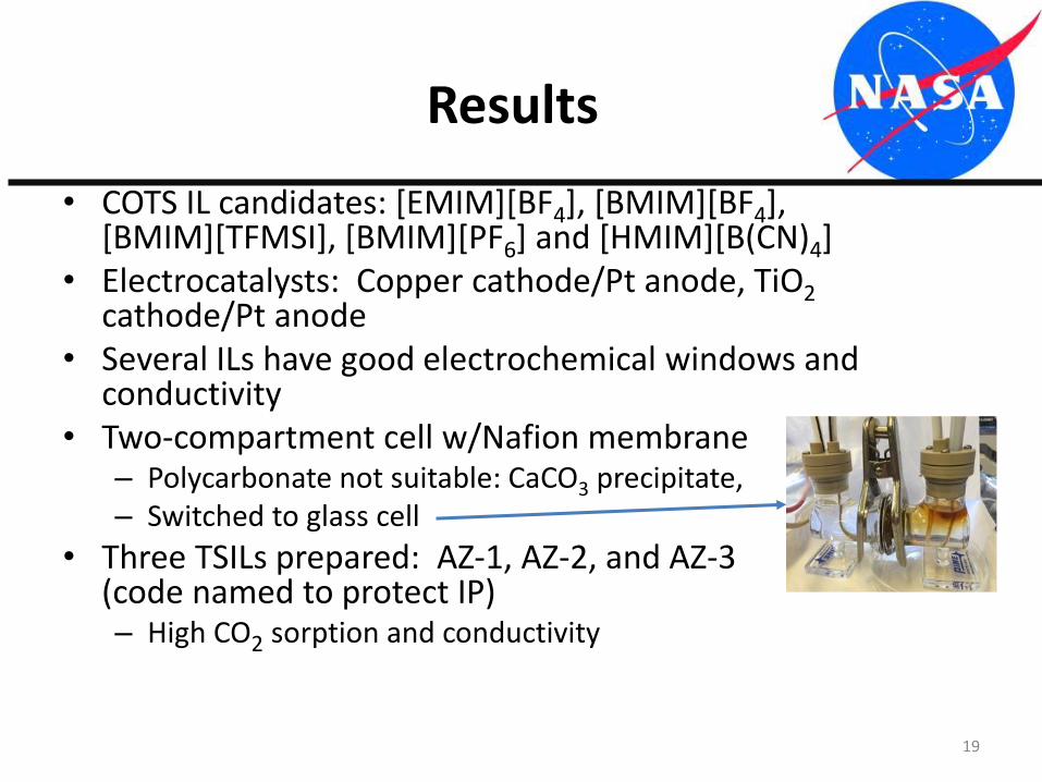
• COTS IL candidates: [EMIM][BF4], [BMIM][BF4], [BMIM][TFMSI], [BMIM][PF6] and [HMIM][B(CN)4]
• Electrocatalysts: Copper cathode/Pt anode, TiO2cathode/Pt anode
• Several ILs have good electrochemical windows and conductivity
• Two-compartment cell w/Nafion membrane– Polycarbonate not suitable: CaCO3 precipitate, Cu corrosion– Switched to glass cell
• Three TSILs prepared: AZ-1, AZ-2, and AZ-3 (code named to protect IP)– High CO2 sorption and conductivity
Results
19
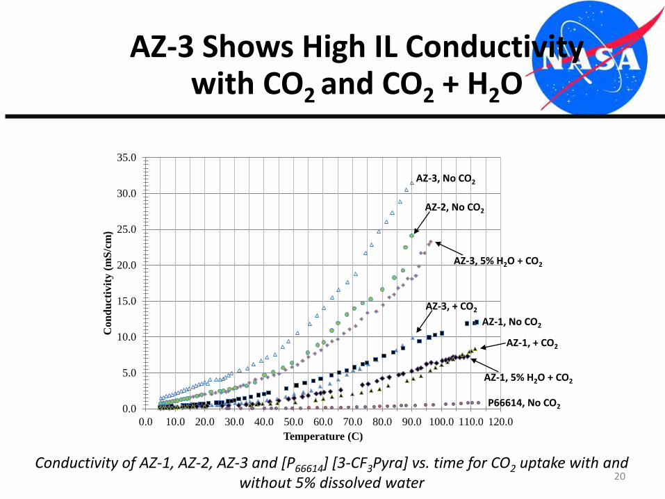
AZ-3 Shows High IL Conductivity with CO2 and CO2 + H2O
20Conductivity of AZ-1, AZ-2, AZ-3 and [P66614] [3-CF3Pyra] vs. time for CO2 uptake with and
without 5% dissolved water
0.0
5.0
10.0
15.0
20.0
25.0
30.0
35.0
0.0 10.0 20.0 30.0 40.0 50.0 60.0 70.0 80.0 90.0 100.0 110.0 120.0
Con
du
ctiv
ity (
mS
/cm
)
Temperature (C)
AZ-3, No CO2
AZ-3, + CO2
AZ-3, 5% H2O + CO2
AZ-2, No CO2
AZ-1, No CO2
AZ-1, 5% H2O + CO2
AZ-1, + CO2
P66614, No CO2
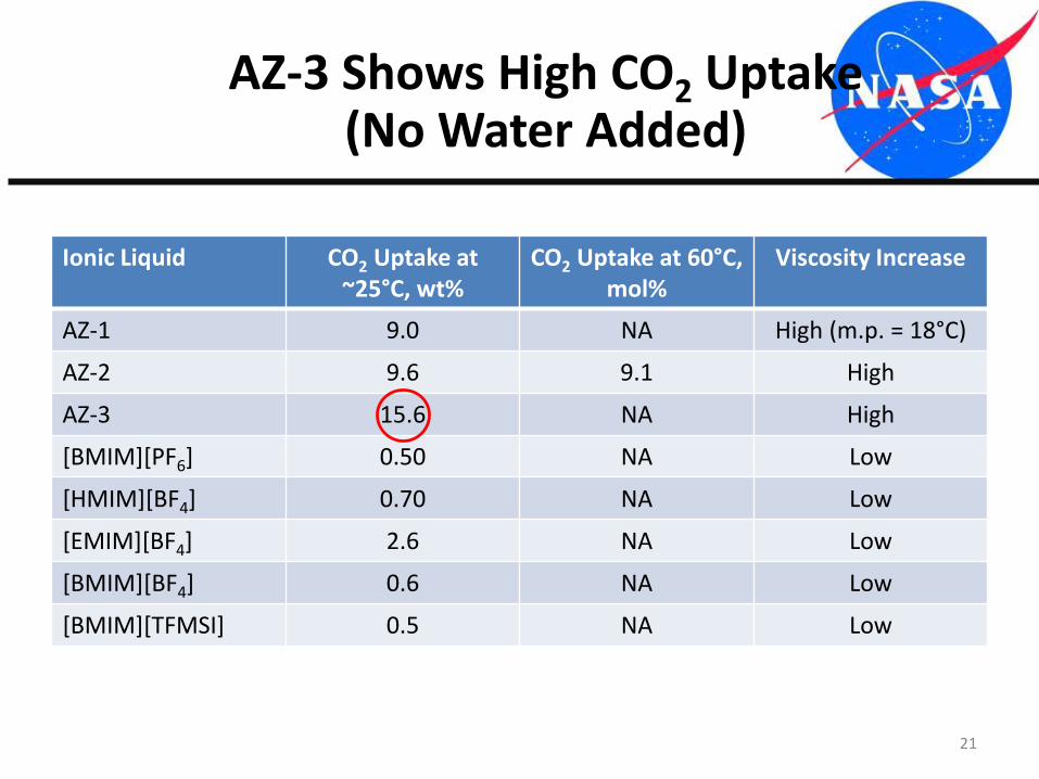
AZ-3 Shows High CO2 Uptake(No Water Added)
21
Ionic Liquid CO2 Uptake at ~25°C, wt%
CO2 Uptake at 60°C, mol%
Viscosity Increase
AZ-1 9.0 NA High (m.p. = 18°C)
AZ-2 9.6 9.1 High
AZ-3 15.6 NA High
[BMIM][PF6] 0.50 NA Low
[HMIM][BF4] 0.70 NA Low
[EMIM][BF4] 2.6 NA Low
[BMIM][BF4] 0.6 NA Low
[BMIM][TFMSI] 0.5 NA Low
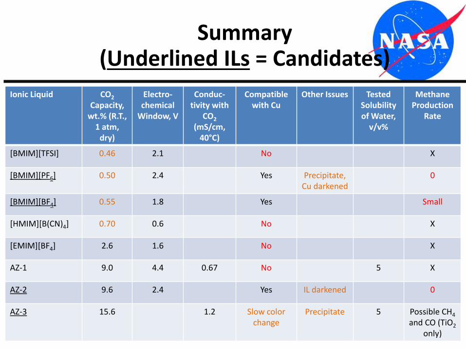
Summary(Underlined ILs = Candidates)
22
Ionic Liquid CO2
Capacity, wt.% (R.T.,
1 atm, dry)
Electro-chemical
Window, V
Conduc-tivity with
CO2
(mS/cm, 40°C)
Compatible with Cu
Other Issues Tested Solubilityof Water,
v/v%
Methane Production
Rate
[BMIM][TFSI] 0.46 2.1 No X
[BMIM][PF6] 0.50 2.4 Yes Precipitate,Cu darkened
0
[BMIM][BF4] 0.55 1.8 Yes Small
[HMIM][B(CN)4] 0.70 0.6 No X
[EMIM][BF4] 2.6 1.6 No X
AZ-1 9.0 4.4 0.67 No 5 X
AZ-2 9.6 2.4 Yes IL darkened 0
AZ-3 15.6 1.2 Slow color change
Precipitate 5 Possible CH4
and CO (TiO2
only)
• Initiated by NASA RFP for “GAME CHANGING DEVELOPMENT PROGRAM, ADVANCED OXYGEN RECOVERY FOR SPACECRAFT LIFE SUPPORT SYSTEMS APPENDIX NH14ZOA001N-14GCD-C2”
• Only 50% of O2 can recovered from respiratory CO2 on the ISS• Sabatier reactor makes CH4 and H2O• CH4 is vented, losing H2
• H2O from cargo limits H2 availability to 50% recovery• RFP seeks at least 75% recovery• Deep space missions (Moon, Mars moons, Mars surface, asteroids,
etc.) need closer to 100% recovery• Joint KSC/FIT/ORBITEC/Pioneer Astronautics proposal was not
selected, but received encouragement from STMD GCD• KSC funded a FY14 CIF project• Completed in July 2015
23
Self-Cleaning BoudouardReactor for Full O2 Recovery
from CO2
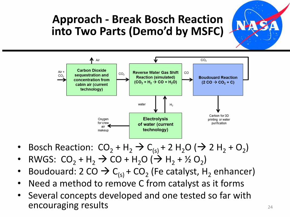
• Bosch Reaction: CO2 + H2 C(s) + 2 H2O ( 2 H2 + O2)• RWGS: CO2 + H2 CO + H2O ( H2 + ½ O2)• Boudouard: 2 CO C(s) + CO2 (Fe catalyst, H2 enhancer)• Need a method to remove C from catalyst as it forms• Several concepts developed and one tested so far with
encouraging results 24
Approach - Break Bosch Reaction into Two Parts (Demo’d by MSFC)
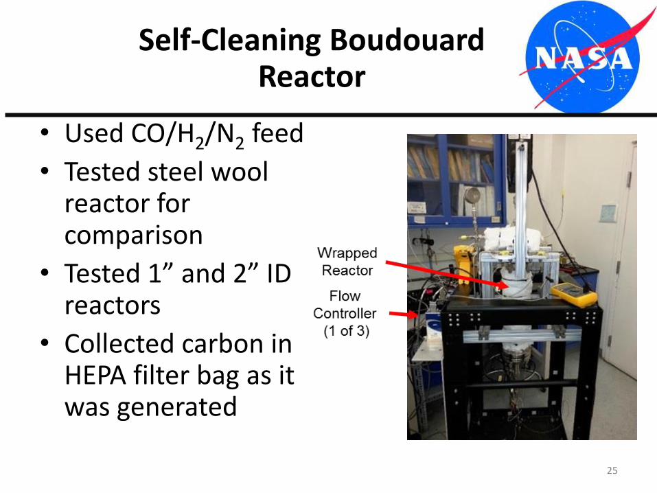
• Used CO/H2/N2 feed
• Tested steel wool reactor for comparison
• Tested 1” and 2” ID reactors
• Collected carbon in HEPA filter bag as it was generated
25
Self-Cleaning Boudouard Reactor
26
Results Are Encouraging
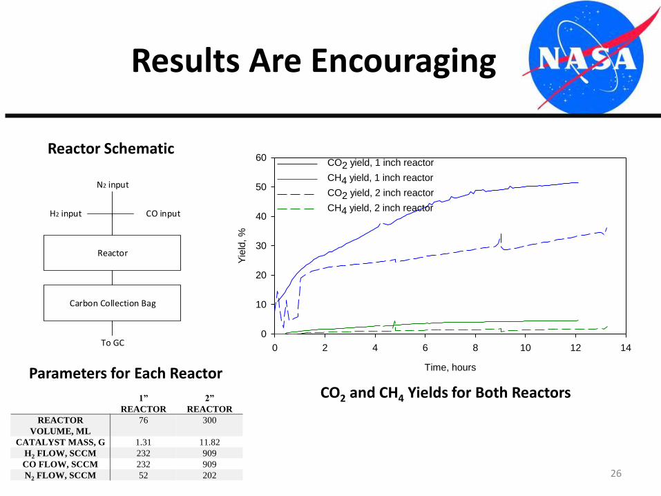
Reactor
Carbon Collection Bag
To GC
CO input
N2 input
H2 input
Reactor Schematic
1”
REACTOR
2”
REACTOR
REACTOR
VOLUME, ML
76 300
CATALYST MASS, G 1.31 11.82
H2 FLOW, SCCM 232 909
CO FLOW, SCCM 232 909
N2 FLOW, SCCM 52 202
Parameters for Each Reactor Time, hours
0 2 4 6 8 10 12 14
Yie
ld, %
0
10
20
30
40
50
60CO2 yield, 1 inch reactor
CH4 yield, 1 inch reactor
CO2 yield, 2 inch reactor
CH4 yield, 2 inch reactor
CO2 and CH4 Yields for Both Reactors
• 1” reactor ran for 12 h– Reached 47% conversion, collected 27% of C in bag– Found to be damaged upon disassembly
• 2” reactor run for 35 h– Reached 40% conversion, collected 60% of C in bag– Equivalent to ~45% of 1 crew CO2 O2/day– Damage was similar to 1” reactor– Evaluating improvements to reactor design
• Lasted much longer than steel wool reactors• Fe, Ni, & Cr seen in carbon fines (corrosion of stainless steel wall)• Will check ability to filter contaminants from air and water• Relevance to Mars: carbon for filters, 3D printing, radiation shielding,
dry lubricant (stable in vacuum), carbothermal reduction for metals production (Fe, Al, Si), diamonds?, terraforming?
27
Boudouard Summary
• KSC is developing both low and higher TRL Mars ISRU technologies
• Significant progress made on Atmospheric Processing Module for methane/oxygen production
• Initial CO2/H2O electrolysis using Ionic Liquids shows more work is needed– NASA Graduate Fellow at KSC this fall
• Very encouraging results so far for Self-Cleaning Boudouard reactor for both O2 recovery from CO2and carbon production
28
Conclusions
29
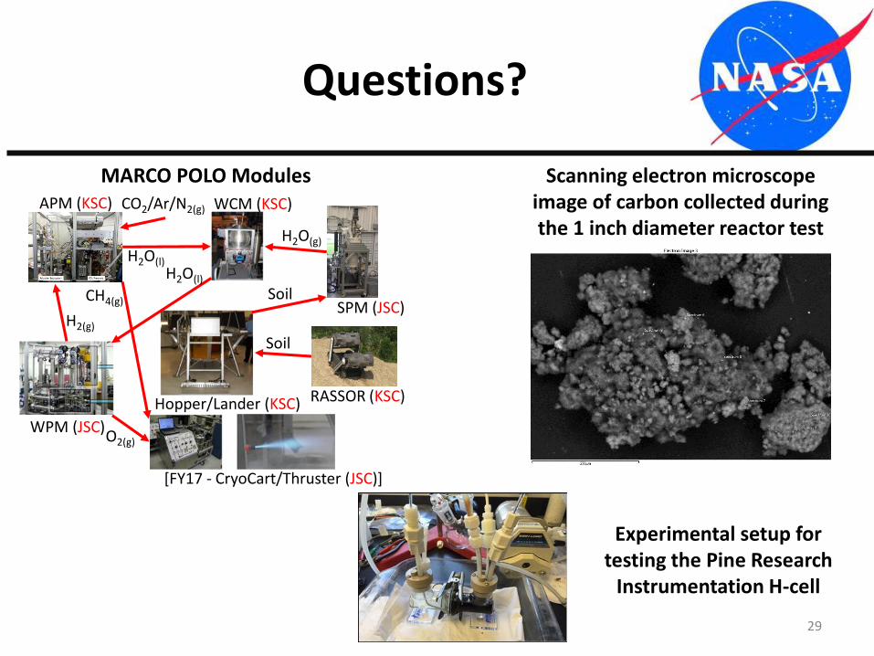
Questions?
APM (KSC)
WPM (JSC)
RASSOR (KSC)
H2O(l)H2O(l)
H2O(g)
O2(g)
H2(g)
[FY17 - CryoCart/Thruster (JSC)]
WCM (KSC)
SPM (JSC)
Soil
SoilCH4(g)
Hopper/Lander (KSC)
CO2/Ar/N2(g)
MARCO POLO Modules Scanning electron microscope image of carbon collected during the 1 inch diameter reactor test
Experimental setup for testing the Pine Research
Instrumentation H-cell