mars mission trade studies and technology...
TRANSCRIPT

Joint Conference of 30th ISTS, 34th IEPC and 6th NSAT, Kobe-Hyogo, Japan
July 4 – 10, 2015
1
Mars Mission Trade Studies and Technology Development of a 36 MW Fusion Rocket
IEPC-2015-68
Presented at Joint Conference of 30th International Symposium on Space Technology and Science
34th International Electric Propulsion Conference and 6th Nano-satellite Symposium, Hyogo-Kobe, Japan
July 4 – 10, 2015
Anthony Pancotti1 MSNW LLC, Redmond, WA 98052
John Slough2, Akihisa Shimazu 3 University of Washington, WA 98195
Abstract: The Fusion Driven rocket (FDR) represents a revolutionary approach to fusion propulsion where the fusion plasma releases its energy directly into the propellant, not requiring conversion to electricity. It employs a solid lithium-based propellant that requires no significant tankage mass. Several low-mass, magnetically-driven metallic liners are inductively driven to converge radially and axially to form a thick blanket surrounding the target plasmoid compressing the plasmoid to fusion ignition conditions. Virtually all of the radiant, neutron and particle energy from the plasma is absorbed by the encapsulating, thick metal blanket. This combined with a large buffer region of high magnetic field isolate the spacecraft from the energetic plasma created by the fusion event. This paper represents the culmination of the FDR program to date. This work includes finalized mission architectures for a favorable single launch 210 day manned Mars mission. It also outlines several mission options for increased payload or faster trip times. In addition experimental results of metallic liner compression will be presented and a path for a future fusion producing experiments will be described.
I. Introduction N order to extend the reach of our space exploration program a significant improvement to propulsion is needed. Fundamentally there are number of challenges to human exploration of our solar system, many of which are
directly associated with trip time and overall mission cost. Whether it is heath issues such as radiation exposure or bone and muscle loss in zero-g, or political issues such as prolong government support or retention of public interest, a faster trip time would mitigate or lessening many critical challenges that face a vast array of exploratory class mission. Large costs also plague any manned space mission. These costs are in the form of either direct costs such as operational cost and the use of complex pre-deployed asset and large space assembly, or indirect costs associated with price to launch mass into low earth orbit (LEO) and beyond. These costs in particular are compounded by the low Isp of chemical systems which require significant more mass in propellant then actual mission payload to perform even the most rudimentary mission outside of the Earth influence. Trip times and cost can both be significantly reduced by new propulsion with higher specific mass (rocket power/spacecraft mass) and higher exit or exhaust velocities. The Fusion Driven rocket (FDR) represents a revolutionary approach which does both these things. This fusion propulsion concept releases its energy directly into the propellant, not requiring conversion to electricity. The propellant is rapidly heated and accelerated to high exhaust velocity (> 30 km/s), while having no significant physical interaction with the spacecraft thereby avoiding
1 Propulsion Lead, [email protected] 2 Res. Assoc. Prof., Aeronautics and Astronautics, [email protected] 3 Graduate Research Assistant, Aeronautics and Astronautics, [email protected]
I

Joint Conference of 30th ISTS, 34th IEPC and 6th NSAT, Kobe-Hyogo, Japan
July 4 – 10, 2015
2
damage to the rocket and limiting both the thermal heat load and radiator mass. In addition, it is believed that the FDR can be accomplished with little extrapolation from currently existing technology, at high specific power (~ 1 kW/kg), at a reasonable mass scale (<100 mT), and therefore cost.1 FDR converts fusion energy directly into thrust. This is achieved by magnetically driven implosion of metal foils onto a magnetized plasma target to obtain fusion conditions.2 A logical extension of this work leads to a method that utilizes these metal shells (or liners) to not only achieve fusion conditions, but to serve as the propellant as well. Several low-mass, magnetically-driven metal liners are inductively driven to converge radially and axially and form a thick blanket surrounding the target plasmoid and compress the plasmoid to fusion conditions. Virtually all of the radiant, neutron and particle energy from the plasma is absorbed by the encapsulating metal blanket thereby isolating the spacecraft from the fusion process and eliminating the need for large radiator mass. This energy, in addition to the intense Ohmic heating at peak magnetic field compression, is adequate to vaporize and ionize the metal blanket. The expansion of this hot, ionized metal propellant through a magnetically insulated nozzle produces high thrust at the optimal Isp. The energy from the fusion process is thus utilized at very high efficiency. Research has focused on achieving three key criteria to allow the Fusion Driven Rocket to move forward for technological development: First (1) is a full understanding and validation of physics of the FDR. Second (2) is the characterization of design and technology development required for implementation in space. And Third (3) is the performance of an in-depth analysis of the rocket engine and spacecraft integration, as well as mission architectures enabled by the Fusion Driven Rocket. A trade study of a variety of mission designs was used to show the potential of the Fusion Driven Rocket and ultimately focused on a manned mission to Mars. A 210 day single launch to Mars was shown to be possible and the most favorable within the design space. A fully scaled spacecraft design was completed for this mission architecture resulting in the scaled model shown in Figure 1. Additionally, mission options were optimized to demonstrate a maximum payload delivered to Mars as well as the fastest possible transit times. Trajectory optimization software was used to show that a 93 day round trip would be possible with a single launch and 69 day round trip if pre-deployed assets are used at Mars. This paper focuses on these finalized architectures that resulted for multiple mission design effort. In addition results from the metallic liner magnetic field compression test done at the Plasma Dynamics Laboratory will be presented. Finally, from these optimistic experimental results, a future experimental design for using metallic liners to compress an FRC plasmoid to fusion conditions will be presented.
II. Fusion Driven Rocket The Fusion Driven Rocket directs the energy for a pulsed magneto inertial fusion (MIF) reaction directly into
thrust. In doing so it creates an efficient high thrust, high Isp, propulsion system needed for next generation space exploration missions. In this section the physics and method for achieving the compressional heating required to reach fusion gain conditions based on the compression of a Field Reversed Configuration plasmoid (FRC) is elucidated. In brief, an inductive technique is employed to accelerate an array of thin, predominantly lithium metal bands radially inward to create a three dimensional compression of the target FRC in a manner compatible with application in space.
It was clear that fusion ignition conditions could be achieved at small scale by transferring the kinetic energy of a significantly more massive metal shell than the target plasma to compress it to high density and temperature. The question now becomes: (1) how to do this without invoking a massive and complex driver (2) how to do it in a manner that is efficient and capable of repetitive operation (3) how to create a suitable magnetized plasma target,
Figure 1. 3D model of a 36 MW FDR spacecraft. This render shows the full spacecraft design, including inflatable habitat as we as properly scaled solar panels and thermal radiator.

Joint Conference of 30th ISTS, 34th IEPC and 6th NSAT, Kobe-Hyogo, Japan
July 4 – 10, 2015
3
and (4) how to transfer the fusion energy into a suitably directed propellant at optimal exhaust velocities and powers for the missions mentioned earlier.
The key to answering all four “hows” is based on previous experimental work employing inductively driven liners to obtain megabar magnetic pressures3,4, and magnetic compression of Field Reversed Configuration (FRC) plasmoids to fusion conditions.5,6,7 A logical extension based on these results leads to a propulsion method that utilizes these metal shells to not only achieve fusion conditions, but then to become the propellant as well. The basic scheme for Fusion Driven Rocket (FDR) is illustrated and described in Figure 2. The two most critical matters in meeting challenges (1) and (2) for MIF, and all ICF concepts for that matter, is driver efficiency and “stand-off” – the ability to isolate and protect driver and thruster from the resultant fusion energy release. By employing metal shells for compression, it is possible to produce the desired convergent motion inductively by inserting the metal shells along the inner surface of cylindrical or conically tapered coils. Both stand-off and energy efficiency issues are solved by this arrangement. The metal shell can be positioned up to a meter or more from the target implosion site with the coil driver both physically and electrically isolated from the shell. The driver efficiency can be quite high as the coil driver is typically the inductive element of a simple oscillating circuit where resistive circuit losses are a small fraction of the energy transferred. Even though there is essentially no magnetic field within the liners initially, there is enough flux leakage during the inward acceleration that at peak compression the axial magnetic field that is trapped inside the now greatly thickened wall can reach as high as 600 T.4
As will be seen this field is considerably higher than that required for the compression of an FRC to achieve ignition and substantial fusion gain.
The next challenge to be considered is the magnetized plasma to be used as the fusion target. Spaced-based fusion demands a much lower system mass. The lowest mass system by which fusion can be achieved, and the one to be employed here, is based on the very compact, high energy density FRC.7 It is of paramount advantage to employ a closed field line plasma that has intrinsically high (plasma/magnetic pressure ratio), and that can be readily translated and compressed, for the primary target plasma for MIF. Of all fusion reactor embodiments, only the FRC plasmoid has the linear geometry and sufficient closed field confinement required for MIF fusion at high energy density. Most importantly, the FRC has already demonstrated both translatability over large distances6 as well as the confinement scaling with size and density required to assure sufficient lifetime to survive the timescale required for compression.
FRCplasmoid
Driver coilsmetalliners
(a)
(b)
(c)
(d)
FRCplasmoid
Driver coilsmetalliners
(a)
(b)
(c)
(d)
Figure 2. Schematic of the inductively driven metal propellant compression of an FRC plasmoid for propulsion. (a) Thin hoops of metal are driven at the proper angle and speed for convergence onto target plasmoid at thruster throat. Target FRC plasmoid is created and injected into thruster chamber. (b) Target FRC is confined by axial magnetic field from shell driver coils as it translates through chamber eventually stagnating at the thruster throat. (c) Converging shell segments form fusion blanket compressing target FRC plasmoid to fusion conditions. (d) Vaporized and ionized by fusion neutrons and alphas, the plasma blanket expands against the divergent magnetic field resulting in the direct generation of electricity from and the back emf and a directed flow of the metal plasma out of the magnetic nozzle.

Joint Conference of 30th ISTS, 34th IEPC and 6th NSAT, Kobe-Hyogo, Japan
July 4 – 10, 2015
4
FRCs can and have been generated with enough internal flux to easily satisfy the B R ignition criteria at peak compression. At a nominal liner converging speed of 3 km/s, a 0.2 m radius FRC typical of operation on the LSX FRC device5 would be fully compressed in 67 s which is only a fraction of the lifetime that was observed for these FRCs (~ 1 msec).7
Finally, to complete the fourth challenge, a straightforward way to convert the fusion energy into propulsive energy must be devised. It is accomplished by employing an inductively driven thin metal liner to compress the magnetized plasma. As the radial and axial compression proceeds, this liner coalesces to form a thick (r > 5 cm) shell that acts as a fusion blanket that absorbs a large fraction of the fusion energy as well as the radiated plasma energy during the brief fusion burn time. This superheated blanket material is subsequently ionized and rapidly expands inside the divergent magnetic field of the nozzle. Here the thermal energy of the plasma is converted into directed propulsive thrust much like in a conventional nozzle but with the crucial difference being that the isolation provided by the magnetic field protects the chamber wall from bombardment by the energetic plasma ions. It would be possible to also derive the electrical energy required for the driver system from the back emf experienced by the conical magnetic field coil circuit via flux compression.8 It was found however that the power required for recharging the energy storage modules for the metal liner driver coils could readily be obtained from conventional solar electric power. For very rapid, high power missions, the flux compressor/generator option could be adopted. For a near-term manned mars mission, solar electric requires the least technology development, lowest cost, and is already at the highest TRL level.
The dynamics of the liner implosion are governed by the set of equations that are used to determine the overall energy released for the MIF reaction.9 Based on this and the known liner mass, which were discussed previously, the exhausted propellant general thrust and Isp performance characteristic can be determine and used for mission design. An in-depth mission designs have shown that a variety of mission applications are possible 10; however, at the conclusion of theses study a single 210 day round trip mission was viewed as most favorable. The details of this design are presented below.
III. Mission Analysis As discussed earlier, the major limiting factors in manned space exploration missions are their long transit times
and high costs. FDR offers a solution that addresses both of these two obstacles by providing a propulsion method that has high specific power, (engine power/spacecraft mass) in addition to high exhaust velocities (Isp). High specific power ( of order unity) significantly reduces trip times, and high Isp (> 3,000 s) dramatically increases payload mass fraction, greatly reducing initial mass at LEO. Mission architecture trade studies have been performed previously over a large range of fusion gains and mission parameters.9 Ultimately, a gain of 200 was fixed and a 36 MW propulsion system has been conceptually designed. The resulting manned Mars mission architecture was optimized to a round trip mission time of 210 days using only a single launch from Earth. The details of this final mission architecture including spacecraft scaling are presented here.
A. 210 Day Round Trip Mission to Mars For the final revision of the single launch manned mission to Mars, several small modifications were made to
previous mission designs.9 Most notably was the modification of the final mass returning to Earth. Originally, it was speculated that only 15 mt would return to earth. However, after the initial investigation and a preliminary scaling of the spacecraft and all of its subcomponents, it was determined that the spacecraft dry mass alone would be about 15 mt and that mass would not include a mass for the crewed vehicle. Therefore, an additional 15 mt was added to the return mass making the total mass return to LEO from Mars to be 30 mt. What this meant from a mission architectural point of view was the majority of the mass would stay in orbit and only a smaller payload would land on the surface of Mars. This seems reasonable in that the vast majority of the mission time (86%) will be spent in transit and only 30 days will be spent on the surface of Mars.
COPERNICUS was used to determine that maximum Mars payload, assuming a limit of a 130 mt initial mass at LEO (IMLEO) and a 30 mt return mass. Confined by the ΔV budget of a 210-day round trip and a 30-day stay, it was found that a 30 mt Mars lander was the maximum Mars payload. This mass was deemed reasonable considering a full Mars orbit insertion using the main FDR engines, which would minimize the thermal protection systems of the entry, descent, and landing systems. It may be worth noting for a sense of scale that the largest spacecraft to land on the surface of Mars was the Mars Science Laboratory, weighing 0.9 mt.
The final mission architecture, therefore, consisted of a Trans-Mars injection maneuver with a ΔV of 7.6 km/s over a 7.2-day period. Total propellant used during this maneuver was 18 mt. The spacecraft would then coast 63.6 days before performing a Mars orbit insertion burn to be captured into a 1 sol Martian orbit. This burn would last a

Joint Conference of 30th ISTS, 34th IEPC and 6th NSAT, Kobe-Hyogo, Japan
July 4 – 10, 2015
5
total of 10.5 days and use 28 mt of propellant to apply a ΔV of 13.8 km/s. This would result in a total outbound trip time of 73.6 days. The spacecraft, including the Mars Transit-habitat and the Fusion Driven Rocket, would remain in orbit for 30 days, while the 30 mt Mars payload would be delivered and left on the surface of Mars. Therefore, the initial mass of the returning spacecraft to Earth would be 53mt. The Trans-Earth maneuver to escape the gravity of Mars and set a trajectory back to Earth requires a ΔV of 16.2 km/s, requiring 15mt of propellant over 5.8 days. Again, the spacecraft coasts for 89.6 days before performing a final Earth orbit insertion maneuver to place the spacecraft back into its original circular 407 km orbit. These maneuvers require 11.9 km/s of ΔV and the remaining 8 mt of propellant. With a burn time of 3.2 days, the total inbound transit time is 98.7 days, resulting in a total mission time of 210 days. Figure 3 shows the plots of the total ΔV and spacecraft mass as a function of mission time.
B. Mission Variation for Faster Trip Times or Larger Payloads Several variations of this mission architecture can be
envisioned. A single launch to Mars was considered as it offered an exciting chance to explore a design space that could not otherwise have been considered without the use of a fusion driven rocket. However from a mission point of view, several launches might make more sense from a practical and safety point of view. So let us briefly consider 2 separate launches with a SLS 130 mt launcher. In this scenario then let us assume that the first launch will be just the spacecraft and Mars payload and the second will be the propellant. Keeping the spacecraft mass and the Mars Trans-habitat the same as the single launch architecture (30 mt), an additional 100 mt of payload for Mars could be launched. Redoing the COPERINUS analysis with this payload, it was determined that 113 mt of propellant would be needed. This would easily fit with the mass limit of the second launch. A mission architecture such as this would have several advantages such as a drastically increased payload to Mars as well as some safety benefits as well, such as launching the crew later and allowing for full system checkout before the Trans-mars insertion maneuver began.
The previously modified mission architecture suggests how multiple launches would drastically increase payload to Mars. Another variant of a manned mission to Mars using FDR would be the fastest mission possible. For this type of mission, both the payload for Mars and the Trans-habitat would be reduced. The payload for Mars would be reduced from 30 mt to 10 mt. The stay time would be also reduced from 30 days to 3 days. This class of mission could be thought of as a precursor or exploratory type mission. Travel time would be faster and less time and equipment would be needed at the surface. Again, for a single launch limit of IMLEO of 130 mt, COPERNICUS was used to determine that the fastest allowable mission time is 93 days. This includes a 38.3 outbound trip, the 3-day stay, and a 51.7-day return trip. The mission details are shown in Figure 4. By removing the single launch limit, only slightly faster trip times are possible. A mission just under 90 day would be possible but would require a total ΔV of 97 km/s and an IMLEO of 170 mt. This does
0 50 100 150 200 2500
10
20
30
40
50
Mission Time (days)
V (k
m/s
)
(a)
0 50 100 150 200 25020
40
60
80
100
120
Mission Time (days)S
pace
craf
t Mas
s (m
t)(b)
Figure 3. (a) ΔV budget and (b) mass plot for the 210-day manned Mars mission design architecture.
Maneuver ΔV
(km/s) Duration
(days) Mi (mt) Mf (mt) Mp (mt) TMI 17.3 14.9 129.4 91.0 38.5 coast 0.0 21.7 91.0 91.0 0.0 MOI 22.9 13.1 91.0 57.0 33.9 stay 0.0 3.0 57.0 47.0 0.0 TEI 23.6 6.9 47.0 29.1 18.0 coast 0.0 29.9 29.1 29.1 0.0 EOI 18.3 3.5 29.1 20.0 9.1
TOTAL 82.1 93.0 99.4 Figure 4. (a) Table of mission parameters for a fast 93 day round trip to Mars using a single launch to LEO.

Joint Conference of 30th ISTS, 34th IEPC and 6th NSAT, Kobe-Hyogo, Japan
July 4 – 10, 2015
6
not really seem worth it, considering it only decreases the mission time by 3%. If trip time is really the key driver for a mission architecture, pre-deployed assets would be necessary. This
means sending propellant to Mars ahead of time so that the spacecraft would only have to carry enough propellant for one leg of the trip. If 46 mt of propellant is waiting on Mars for the return trip, a total mission time of 69 days, with a 3-day stay, would be possible at a ΔV of 119 km/s. It is worth noting that the IMLEO is only 68 mt for the manned mission, but recall that this does include the 46 mt that would have been launched early and deposited in Mars orbit. As illustrated here, the fastest trip time is capped due to the thrust that can be produced within a chosen power limit. Recall that for all the mission architecture investigated, the engine Isp is limited to 5000s and a power of 36 MW. With more power accessible and/or lower Isp, faster missions could be achieved.
IV. FDR Experimental Validation & Future Developments The greatest challenge for the FDR concept is in demonstrating the feasibility of inductively-driven, metal liner
compression of the FRC plasma to fusion ignition. An experiment to explore the physics and technology needed for a next-step fusion gain demonstration was constructed and operated by the MSNW team in collaboration with the Plasma Dynamics Laboratory (PDL) at the University of Washington to address this challenge. They have shown that large magnetic field compression to hundreds of Tesla is possible. The experiment as well as the requirements for the next generation of experiments that would be needed to demonstrate fusion yields with liner compression of an FRC plasmoid are presented.
A. Magnetic Field Compression with Metallic Liners As FRCs have been made with the density, temperature, lifetime and scale for liner compression, the risk
involved in performing the next-step liner compression of the FRC, comes from consideration of the possible instability of the liner implosion. On the liner side, the greatest risk will come from instability in the plasma wall boundary during FRC compression. In conducting the smallest scale experiments performed (rcoil = 6 cm, rLiner = 5 cm), the driver magnetic fields attained were as large as those anticipated for the 2MJ bank compression required for a fusion gain experiment which will require a much larger 15 cm radius coil. The transiently high magnetic fields do not appear to be a major issue. High current density (and thus magnetic fields) in the feed plates can be an issue. A series of G-10 clamps reinforced by steel beams has proven sufficient in these experiments (see Fig. 5), and the ANSYS calculations indicate this should be adequate for the fusion gain experiments.
In the small liner experiments the liners converged with no apparent buckling, as is also observed in other small scale inductively driven liner experiments4. Experiments conducted with 10 cm radius liners did show some buckling (see Fig. 6), but there was no issues observed from this buckling at peak field compression (arcs, jets etc.).
The small liners were fabricated from 6061 Aluminum tubes machined to a thickness of 0.5 to 0.75 mm. Alternatively aluminum strip was seam welded together and annealed for larger liners. The weld was ground to maintain as best as possible the thickness, thermal and resistive properties of the bulk material. The liners were placed inside the vacuum chamber under each driver coil. The principle diagnostics that were employed to determine liner position as a function of time were several internal magnetic probes on axis, as well as external axial flux and B loops. End-on images of the liner motion were also obtained with a backlit fast framing camera as in the Cnare experiments.3 These images yield detailed information regarding liner uniformity during convergence. The ANSYS 3D Explicit Dynamics® Solver (AEDS) was used to characterize the liner dynamics in 3D. These calculations were carried out with the same material, dimensions and magnetic pressure time history as the liners. The near identical results validate the use of the AEDS code for accurately predicting liner dynamics in designing future liner implosion systems. The buckling seen in both experiment and calculations occurs fairly early in the implosion. It appears that the early buckling serves two useful functions in that it minimizes the energy lost to compressional internal energy in the liners, and, as the liners
Figure 5. Feedplate clamping on current FRC liner source experiments at the Plasma Dynamics Laboratory.

Joint Conference of 30th ISTS, 34th IEPC and 6th NSAT, Kobe-Hyogo, Japan
July 4 – 10, 2015
7
move inward, the buckles naturally merge together to form a thick, compact stable wall at peak compression as desired. As one would imagine, all large ratio liners (radius to thickness) are susceptible to buckling. The ability to form very uniform folds or buckles will be important in order to avoid azimuthal non-uniformities at peak compression.
Interestingly, virtually all of the damage generated by the imploded liners was created by axial jets consisting of aluminum vapor and, for lower kinetic energy liners, small bits of aluminum fragments. There was little if any damage to the vacuum wall under the driver coils, even with liner/drivers as small as 10 cm radius. The conversion of radial kinetic energy into axial kinetic energy appears to be a natural consequence of the inductively driven magnetized liner implosions. The high energy liners were rapidly heated and melted by Ohmic currents flowing in the liner. As the liner collapses on axis, the magnetic field increases dramatically as the axial magnetic field, which had diffused through the liner during the initial acceleration, is rapidly compressed to very high values. The metal liner prohibits the diffusion of this flux on the short timescale of the final implosion, and the rapidly increasing and very large induced current quickly heats, melts and atomizes the liner. Without significant heating from the fusion event however, there is no significant liner ionization. The axial jet-like behavior of the aluminum vapor is thus not a result of a plasma interaction with the axial magnetic field, but a consequence of the magnetic field on the implosion physics while the liner is still intact and a good conductor. Since magnetic field effects are not yet a direct part of the AEDS calculations, how this all unfolds is still not well known. A major part of future theory effort will be directed at a better understanding of this phenomenon as it is critical to the design of the eventual rocket system.
Much of the work on testing the 3D liner convergence utilizing the inductively driven liner process was done on smaller radius liners where the liner velocities and coil modifications were more favorable. It was found that two liners, properly driven, were sufficient to produce the desired 3D liner convergence. Experiments were conducted over a range of liner geometries and demonstrated such convergence to compression fields well in excess of 4 gigaPascal (100 T). The peak magnetic fields that were attained were certainly higher, as B probe failure occurred well before reaching peak fields. This was mainly due to insufficient wire insulation. A much more reliable and accurate optical Faraday rotation system will be adopted for these studies.
An example of the performance of two merging liners initially at 10 cm radius is shown in Fig. 6. The speed of the liner implosion is a critical element for successful compression of the FRC as it must occur on a timescale smaller than the FRC lifetime. This is essentially an energy storage and delivery issue which can be readily solved by employing a suitably high voltage and large capacitance pulse power system with low stray inductance.
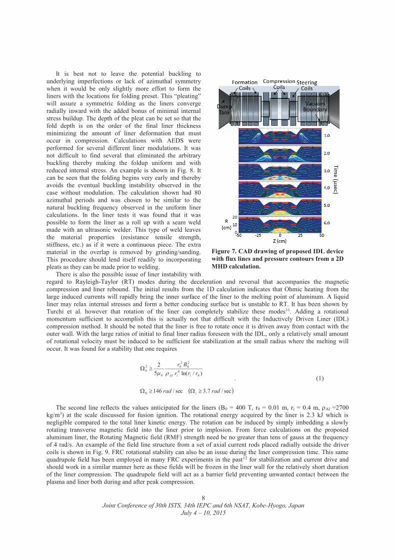
With inductive drive it is possible to induce an axial convergence of the liners in numerous ways. Several methods have been devised and tested to achieve liner axial convergence from as simple as a small axial displacement of the liner from directly centered under the driver coil as was done in the experiments, to a tapered coil and liner9. The AEDS code has been found to give accurate representation of the liner physics in 3D. The method to be employed in the next-step experiment, the use of a steering coil proved to allow for the greatest control and simplicity (see Fig. 7). This also allows for the use of simple cylindrical aluminum liners that, at least initially, act as independent elements driven radially inward in a symmetric fashion. This also provides for the liner dynamic motion to be described by a simple 1D model through the acceleration phase.9
Figure 6. End-on backlit images of two 10 cm radius liners simultaneously imploded on the FDR experiment at PDL.
Joint Conference of 30th ISTS, 34th IEPC and 6th NSAT, Kobe-Hyogo, Japan
July 4 – 10, 2015
8
It is best not to leave the potential buckling to underlying imperfections or lack of azimuthal symmetry when it would be only slightly more effort to form the liners with the locations for folding preset. This “pleating” will assure a symmetric folding as the liners converge radially inward with the added bonus of minimal internal stress buildup. The depth of the pleat can be set so that the fold depth is on the order of the final liner thickness minimizing the amount of liner deformation that must occur in compression. Calculations with AEDS were performed for several different liner modulations. It was not difficult to find several that eliminated the arbitrary buckling thereby making the foldup uniform and with reduced internal stress. An example is shown in Fig. 8. It can be seen that the folding begins very early and thereby avoids the eventual buckling instability observed in the case without modulation. The calculation shown had 80 azimuthal periods and was chosen to be similar to the natural buckling frequency observed in the uniform liner calculations. In the liner tests it was found that it was possible to form the liner as a roll up with a seam weld made with an ultrasonic welder. This type of weld leaves the material properties (resistance tensile strength, stiffness, etc.) as if it were a continuous piece. The extra material in the overlap is removed by grinding/sanding. This procedure should lend itself readily to incorporating pleats as they can be made prior to welding.
There is also the possible issue of liner instability with regard to Rayleigh-Taylor (RT) modes during the deceleration and reversal that accompanies the magnetic compression and liner rebound. The initial results from the 1D calculation indicates that Ohmic heating from the large induced currents will rapidly bring the inner surface of the liner to the melting point of aluminum. A liquid liner may relax internal stresses and form a better conducing surface but is unstable to RT. It has been shown by Turchi et al. however that rotation of the liner can completely stabilize these modes11. Adding a rotational momentum sufficient to accomplish this is actually not that difficult with the Inductively Driven Liner (IDL) compression method. It should be noted that the liner is free to rotate once it is driven away from contact with the outer wall. With the large ratios of initial to final liner radius foreseen with the IDL, only a relatively small amount of rotational velocity must be induced to be sufficient for stabilization at the small radius where the melting will occur. It was found for a stability that one requires
sec/7.3sec/146
)/ln(52
0
04
20
20
0
20
radrad
rrrBr
i
iiAl . (1)
The second line reflects the values anticipated for the liners (B0 = 400 T, r0 = 0.01 m, ri = 0.4 m, Al =2700
kg/m3) at the scale discussed for fusion ignition. The rotational energy acquired by the liner is 2.3 kJ which is negligible compared to the total liner kinetic energy. The rotation can be induced by simply imbedding a slowly rotating transverse magnetic field into the liner prior to implosion. From force calculations on the proposed aluminum liner, the Rotating Magnetic field (RMF) strength need be no greater than tens of gauss at the frequency of 4 rad/s. An example of the field line structure from a set of axial current rods placed radially outside the driver coils is shown in Fig. 9. FRC rotational stability can also be an issue during the liner compression time. This same quadrupole field has been employed in many FRC experiments in the past12 for stabilization and current drive and should work in a similar manner here as these fields will be frozen in the liner wall for the relatively short duration of the liner compression. The quadrupole field will act as a barrier field preventing unwanted contact between the plasma and liner both during and after peak compression.
Figure 7. CAD drawing of proposed IDL device with flux lines and pressure contours from a 2D MHD calculation.

Joint Conference of 30th ISTS, 34th IEPC and 6th NSAT, Kobe-Hyogo, Japan
July 4 – 10, 2015
9
To obtain a sufficiently predictive theoretical understanding of the liner and plasma dynamics would be extremely useful going forward. This task is inherently a 3D one, and it may be quite feasible to have separately accurate 3D models of FRC plasma and liner. The combining of these two, particularly in regard to the effects of fusion and possible ignition, make for a very challenging goal. The risk here is mitigated by employing the most experienced and best FRC modelers together with tremendously powerful and accurate commercial codes. In this way it is hoped that this important task can be successfully completed.
The primary diagnostic of plasma compression and heating will be the neutron count from the D-D fusion reaction. The yield is a sensitive measure of ion temperature. The signal will be analyzed using MCNP codes used in previous FRC experiments. A time resolved Doppler spectrometer could be employed to confirm the plasma ion temperature as long as there is a gap between the liners. It is hoped that it will be possible to leave a small gap through the peak implosion and provide more data as to the final FRC plasma state than could be obtained from end on measurements alone. Through this same gap the plasma density can be obtained from a cross-chamber HeNe laser-based interferometer.
With the liner compression of the axial magnetic field and FRC to 200 T, the final ion and electron temperature (the high plasma density will assure that Te = Ti at that time) is given by the adiabatic scaling laws (see Ref. 9) i.e., Ti+Te (final) = Ti+Te (initial) (Bf/Bi)4/5 = (500 eV) (60), or Ti = 15 keV which would be well inside the parameter space needed for high fusion gain in a D-T plasma (5 -20 keV). Such a result would clearly validate this approach for obtaining appropriate fusion plasma for fusion powered propulsion represented by the Fusion Driven Rocket.
B. Experimental Design for the Inductively Driven Liner (IDL) Compression of an FRC Plasmoid The process for achieving the temperature and density required to reach fusion gain conditions is based on the
straightforward, adiabatic compression of a Field Reversed Configuration (FRC) plasmoid. The methodology for achieving this stems from current research being done at MSNW and the University of Washington (UW) on the magnetically driven implosion of thin (0.5–1 mm) aluminum hoops, as well as the simultaneous merging and magnetic compression of two FRCs. This process was first demonstrated at MSNW, and provides for a way to form a suitable FRC target inside the metal bands. Both the driver and the target have been studied experimentally and theoretically by the MSNW/UW team with success. FRCs have been formed, translated and merged inside compression coils no larger than those anticipated in the IDL concept (rc~ 6 cm), and magnetically compressed up to ion temperatures over 3 keV with observed target lifetimes in excess of that required for liner compression. Aluminum liners with radii from 6 cm to over 40 cm have been successfully imploded. The smaller liners reaching the 2 km/sec inward velocity desired for rapid FRC target compression, achieving
Figure 8. (Top) Evolution of one of the Al solid liners planned for IDLP from an AEDS calculation as function of time (ten sec intervals starting at 0). (Bottom) Evolution of the same liner but with a modulation in thickness with a periodicity of 4.5 as function of time.
Figure 9. 2 phase coil configuration for rotational stabilization of the liner with a rotating quadrupole magnetic field.

Joint Conference of 30th ISTS, 34th IEPC and 6th NSAT, Kobe-Hyogo, Japan
July 4 – 10, 2015
10
compression fields greater than 100 T in the process. Due to the energy (i.e. voltage) restrictions dictated by an antiquated pulse power system, and limited funding resources for this work, it was not possible to perform the most critical step, that being the combined, simultaneous operations of FRC formation, merging and liner compression. However the prime objective of the next-step facility is to perform this most important test of the concept, and to do it at sufficient power and scale to achieve scientific gain conditions.
While the final critical test awaits further funding, it was possible to make comprehensive plans for this next step. A detailed 1D analytical model of the liner dynamics that included a full electrical circuit and liner physical parameters (Ohmic heating, flux diffusion, etc.) was developed. Using this code, the optimal liner physical dimensions and composition, as well as the driver electrical parameters to meet the goal of a fusion gain test were determined (see Fig. 10). The full, non-linear, dynamical behavior of the liner assembly was studied using the ANSYS 3D Explicit Dynamics® solver (AEDS). It was found that these calculations produced a very accurate description of the liner dynamics observed in the experiments, predicting liner convergence velocity as well as all of the crenellations observed in end-on images taken of the liner during implosion4. The coil set and magnetic field configuration for the generation, translation and merging of FRCs required for both the next step IDL device, as well as a reactor scale facility was also determined using the resistive 2D MHD code known as Moqui.
For the goal of fusion gain outlined here it is desirable to increase the driver bank energy into the regime where the compressed magnetic field is large enough to achieve fusion gain when compressing a suitable FRC target. As indicated in Fig. 10, and to be justified in the following discussions, a bank energy of 2 MJ should be sufficient to accomplish that goal. Based on both AEDS and the 1D liner+circuit modeling to be described, coupling efficiencies greater than 30% of the bank energy into kinetic liner energy can be achieved. For a ~1 plasma such as the FRC that essentially fills the liner with only a small annulus of flux surrounding it, the coupling efficiency of liner kinetic into plasma thermal energy will be high. It will be assumed that roughly 75% of the liner kinetic energy is converted into plasma energy at stagnation. One has then:
kJkTNkTNE eeiip 45023
00, (2)
where the subscript 0 denotes the value at peak compression. Ni(e) is the total ion (electron) inventory, and Ep is the plasma energy. It will also be assumed that N = Ni = Ne and that T = Ti = Te at maximum compression. It will be assumed for now that the target plasmoid has been inserted into the liner with the initial conditions such that when it is adiabatically compressed to an energy density ~ 30 gigaPa (280 T), it will have physical parameters suitable for fusion gain. For an elongated, cylindrically shaped FRC plasmoid (ls = 10 rs), that has been compressed to an energy density = 3 1010 Pa (B = 280 T), one has for the plasma volume and dimensions:
cmlcmrmE
rVol ssp
s 6.7,76.0104.110 353 . (3)
Assuming that the final desired Ti = Te = 15 keV, the plasma inventory and peak density can be determined from Eqs. (2) and (3), that being 6.2 1019 (a typical FRC inventory) and 5 1024 m-3 respectively.
The choice of the metal for implosion is important, particularly if it is to be used for fusion applications. As was first pointed out by Cnare3, a material’s electrical and thermal properties determine the liner’s minimum thickness (mass) for a given liner velocity (energy) when driven by the inductive technique in order to avoid vaporization due
Figure 10. Basic parameters from the 1D liner model for the next step IDL device and those of a reactor. Fusion gain was determined using the adiabatic scaling laws for FRC compression and energy conservation. Assuming a simple bounce model for the liner dynamics9:
8/118103.4 LLL
fus EME
EG

Joint Conference of 30th ISTS, 34th IEPC and 6th NSAT, Kobe-Hyogo, Japan
July 4 – 10, 2015
11
to Ohmic heating from the induced currents. The material properties relating to this resistive heating (electrical conductivity, melting point, heat capacity, etc.) can be characterized by a parameter gM defined by the “current integral”:
2
0
2 AgdtI M
tm (4)
where I is the current flowing through the material cross-sectional area, A = w δ, where w is the hoop width and δ is the hoop thickness. The driving force is simply the magnetic pressure (B2/2μ0) applied over the surface area of the metal shell facing the coil when in close proximity to the driving coil. The current can be related to the force through Ampere’s law which can be reasonably approximated as B = μ0I/w. Normalizing to the action constant, gAl for the vaporization of aluminum from an initial temperature of 300 °K, one finds for the maximum velocity for a given shell thickness δ:
)/(105.2 7 smggxv
M
Al
Al
Mm
, (5)
where M is the shell material density. This is usually not a significant issue during FRC compression phase due to the formation of a thick wall at convergence, but the initial thickness should typically be much greater than needed for the characteristic velocities (2 km/s) anticipated. The relatively strong dependence on conductivity favors a good conductor such as aluminum. A lithium shell could be especially advantageous in that the initial thin shell could be readily extruded for positioning under the coil between pulses. Besides having a low yield strength, lithium also has other advantages as a liner material. Recall that the ultimate fate of the imploded liner in the presence of significant fusion gain is melting, followed by vaporization and possible ionization after intense fusion neutron, alpha and radiative heating. Lithium is favored for its breeding potential, high vaporization temperature and very low ionization energy. The advantages of aluminum are also many – inexpensive, easy to handle, high electrical conductivity, and structurally sturdy yet malleable. For the gain demonstration the obvious choice is aluminum as it was for the initial work on the Foil Liner Compression (FLC) experiments at MSNW and the Fusion Driven Rocket (FDR) experiments at PDL. Aluminum is also readily available in virtually any thickness, it is safe to handle, and has good vacuum properties. With the use of a thin liner at larger radius there is a hidden benefit in that a significant axial buffer field between the FRC and liner is provided from flux leakage through the liner during the initial stages of acceleration. This external field, Bext, then diffuses into the cylinder with a characteristic diffusion time given by = ½ 0 rL L, where rL is the initial (inner) cylinder radius, and L is its electrical conductivity. The diffusion of the field is governed by the equation:
inext
in BBdt
dB . (5)
The dynamics of the liner implosion are then governed by the equation:
wrBBdt
rd extinL 2
22 0
2
0
2
2
2 (6)
where ML is the liner mass, and w the liner width.
With the initiation of the -pinch current the field rises rapidly in the small radial gap between the external coil and the liner as the liner acts to shunt virtually all of the coil inductance. A large driving field is rapidly developed. Striking evidence of this was observed on the Plasma Liner Compression experiment6 at MSNW. With a close fitting driver coil, the plasma sheath formation at the inner vacuum wall eliminated most of the coil inductance and
0
0.2
0.4
-2 -1 0 1 2 3 4time ( sec)
Vacuum B-Field
With Plasma Liner
0.6
Bext
(T)
0
0.2
0.4
-2 -1 0 1 2 3 4time ( sec)
Vacuum B-Field
With Plasma Liner
0.6
Bext
(T)
Figure 11. Magnetic field at the compression section midplane measured between the theta pinch coil and the vacuum wall with and without the xenon plasma liner.

Joint Conference of 30th ISTS, 34th IEPC and 6th NSAT, Kobe-Hyogo, Japan
July 4 – 10, 2015
12
caused a much more rapid rise in the current as only the stray inductances of the external circuit (cables, switches, and coil-sheath gap) provide the only significant impedance to current flow. The rapid current rise was readily detected by the external magnetic probes positioned radially between the coil and the vacuum tube wall. The drop in field after liner lift-off (~ 1 μsec in Fig. 11) below that of the vacuum field is a reflection of the energy transfer to the liner which was over 50% in these experiments.
It can be seen from Eq. (5) that for a high conductance liner during liner acceleration, very little flux leaks through the liner (Bin << Bext). With the greater inertia of a solid metal liner, the magnetic field maintains a roughly constant amplitude (Bext ~ const.) during this time with the increase in flux in the gap countered by the increasing gap cross-sectional area. With this assumption, Eq. (6) is now readily integrated. With the liner mass ML = 2 rLw Al where is the liner thickness and Al the density of Aluminum, the liner velocity is:
24/12
0
1252
)(extext
AlLL BtB
rtrv , (7)
where the approximation is made that the liner is accelerated at roughly constant field up to the time when the liner has moved inward to r = 0.8 rL. From a circuit efficiency point of view, this should occur at the point of maximum energy transfer into the driver coil. This will occur at the quarter cycle time 1/4 of the driver circuit, when the bank is typically crowbarred to preserve the flux in the driver coil. Thus the effective drive time t ~ 1/4 is determined by the bank capacitance and coil inductance at this time. This determines Bext as the magnetic field energy cannot be greater than stored energy minus the anticipated liner energy which is (2 – 0.6) MJ ~ 1.4 MJ for the proposed IDL gain experiment energy storage. Equating this to the magnetic energy stored in the annuli of the liners yields a magnetic field Bext = 30 T in the gap when the liner has moved inward by 20% of the initial coil (liner) radius of 0.15 m. While this is a large field its transient nature allows for the coil to tolerate the large magnetic force, and well below the yield strength of several structural materials. Employing ANSYS® structural analysis on the coil design chosen for the Inductively Driven Liner Prototype (IDLP) device (see Fig. 12), it was found that coils constructed from 7075 aluminum were sufficient to handle the integrated force during the liner drive without exceeding elastic limits of the material and early fatigue failure from repetitive operation.
The voltage needed to produce the required field in the gap on the appropriate timescale is given by:
kVBrBAV extL 48
22
4/1
, (8)
Figure 12. (top) CAD rendering of the 30 cm ID driver coils to be employed on the IDL prototype (feedplate clamps not shown for clarity). (middle) ANSYS Maxwell® calculation of the magnetic field based on the actual driver circuit to be employed. (bottom) ANSYS Structural® calculation the coil stresses at 20, 40 and 60
sec.

Joint Conference of 30th ISTS, 34th IEPC and 6th NSAT, Kobe-Hyogo, Japan
July 4 – 10, 2015
13
While the liner continues to be accelerated, the rate drops dramatically as the area between the coil and liner grows but the capacitor bank energy has been fully transferred to the coil. For the liner to have moved inward 3 cm in 20 μsec under a constant magnetic force implies a terminal velocity of vL =2.3 km/s. This is consistent with Eq. (7) which predicts a velocity of 2.5 km/s. Given the inevitable Ohmic and internal compressive energy losses, a velocity of 2 km/sec is more realistic and agrees with more detailed analysis. With a nominal liner kinetic energy of 560 kJ the total liner mass can now be determined with ML = 0.28 kg. These are both consistent with Fig. 10 based on more detailed modeling. Assuming two 7.5 cm wide Aluminum liners implies a liner thickness = 0.75 mm (30 mil).
While this simple analysis is useful for grasping the basic requirements and scaling dependencies, details of the liner implosion process is best studied and understood using the 1D liner code that was developed for this purpose. The model was designed to investigate the dynamic behavior of the liner-driver system where all the relevant magnetic fields, forces, currents, fluxes, Ohmic heating, and circuit behavior were included in order to optimize the design of the IDLP. It is paramount that the liner kinetic energy be determined accurately as this is the major factor that determines the fusion yield. Crucial to this end was the accurate determination of the coupling between the liner and driver coil as the liner moves radially inward. The following procedure was carried out to properly determine this coupling for the actual geometric dimensions of both the coil and liner. The total circuit inductance was first determined from the 3D electromagnetic code ANSYS Maxwell® over a range of liner radial positions and coil currents. The calculations were based on a single drive coil with a 0.15 m inner radius and an axial length of 7.5 cm as proposed here for the IDL prototype to be tested. The actual coil to be fabricated was fully designed and specified in SolidWorks® and imported into ANSYS Maxwell® (see Fig. 12). This code solves for the magnetic field in 3D for a given drive circuit, but is not capable of solving the full dynamic motion of the liners placed within the drive coil. However it can solve for the fields and effective inductances for liners of various radii and location. This code was thus used to determine the magnetic field and radial forces for a given drive current at a specific liner radius. A table of these values was created and used in the 1D model. The ANSYS Maxwell® data was fit with a smoothing spline function, so that the data could be interpolated to the exact liner radius determined by the 1D model.
The circuit equations were based on the actual experimental circuit parameter values anticipated for the Inductively Driven Liner Prototype (IDLP). The results for the liners to be employed in the FRC compression experiments are shown in Fig. 13. Slightly lower bank energy was assumed to account for losses not in the model such as the internal liner compressive stress energy. As can be seen the model supports the conclusions from analytic calculations. It should be noted that the 0.75 mm thick Aluminum liner stays well below the melting point (934 K) until the induced currents from the final compression of the internal magnetic field (and FRC) rapidly
Figure 13. Results from the 1D code showing various liner and magnetic field parameters as a function time for the next step IDLP.
Joint Conference of 30th ISTS, 34th IEPC and 6th NSAT, Kobe-Hyogo, Japan
July 4 – 10, 2015
14
increase the liner temperature. It can also be seen that the coupling efficiency is still 30% while accounting for all resistive losses and circuit stray inductance. The liner also achieves the desired velocity of 2 km/sec.
In summary, the development of the IDLP for the three dimensional magnetic compression of the Field Reversed Configuration to fusion gain conditions would make for a genuinely transformational solution to the generation of fusion energy for space propulsion. If successful, it would lead to a dramatic reduction in facilities costs for fusion propulsion development and the early entry of fusion as an energy source for space travel. The demonstration and validation experiment will enable rapid advancement of the physics and technology of the IDL concept. The IDL prototype device outlined here would serve as a smaller-scale, working prototype of a follow-on system to be developed for space. It could be used to demonstrate all essential aspects of the reactor from the ability to form, heat, and confine plasmas at performance levels that will establish the viability as a source of propulsive power for planetary manned missions.
Acknowledgments The authors would like to acknowledge the financial and administrative support from the NASA Innovative
Advanced Concepts program (NIAC) and staff. Without their support and encouragement none of this work would have been possible. The authors would also like to acknowledge the expertise, dedication, and craftsmanship of their technical staff: Rorm Arestun (UW), Kyle Holbrook (MSNW) and Chris Pihl (MSNW).
References
1 Pancotti, A., Slough, J. Kirtley, D. et al. AIAA Joint Propulsion Conference (2012). 2 Slough, J. Kirtley, D. Pihl, C. and Pancotti, A., NASA NIAC Symposium (2012). 3 Cnare, E.C., “Magnetic Flux Compression by Magnetically Imploded Metallic Foils”, Journal of Applied
Physics, Vol. 27, No. 10, pg. 3812, (1967) 4 Y. H. Matsuda, F. Herlach, S. Ikeda, and N. Miura, “Generation of 600 T by electromagnetic flux compression
with improved implosion symmetry”, Rev. Sci. Instrum. 73 4288 (2002). 5 Slough J., et al., "Confinement and Stability of Plasmas in a Field Reversed Configuration", Phys. Rev. Lett.,
Vol. 9, 2212 (1992) 6 G. Votroubek and J. Slough, “The Plasma Liner Compression Experiment”, Journal of Fusion Energy 29, 571
(2010) 7 Slough J.T., et al “Transport, energy balance, and stability of a large field-reversed configuration”, Physics of
Plasmas 2, 2286 (1995) 8 A.A. Harms, K.F. Schoepf, G.H. Miley, D.R. Kingdom, 2002 Principles of Fusion Energy, World Scientific
Publishing, Singapore 912805, pgs. 267-277. 9 Slough, J., Kirtley, D., and Pancotti, A., Votroubek, G., Electromagnetically Driven Fusion Propulsion, IEPC-
2013-372 (2013) 10 Pancotti, A., Slough, J. Kirtley, D., Votroubek, G., Pihl, C., The Fusion-Driven Rocket, Advanced Space
Propulsion Workshop, (2014) 11P.J. Turchi, A.L. Cooper, R.D. Ford, D.J. Jenkins, “Rotational Stabilization of an Imploding Liquid
Cylinder”, Phys. Rev. Lett. 36, 1546 (1976). 12J.T. Slough and K.E. Miller, Phys. Rev. Lett. 85 1444 (2000).