martin® v-plow hd
TRANSCRIPT

Martin® V-Plow HD
Operator’s Manual M3201
Go to Martin® V-Plow HD web page

ImportantMARTIN ENGINEERING HEREBY DISCLAIMS ANY LIABILITY FOR: DAMAGE DUE TO CONTAMINATION OF THE MATERIAL; USER’S FAILURE TO INSPECT, MAINTAIN AND TAKE REASONABLE CARE OF THE EQUIPMENT; INJURIES OR DAMAGE RESULTING FROM USE OR APPLICATION OF THIS PRODUCT CONTRARY TO INSTRUCTIONS AND SPECIFICATIONS CONTAINED HEREIN. MARTIN ENGINEERING’S LIABILITY SHALL BE LIMITED TO REPAIR OR REPLACEMENT OF EQUIPMENT SHOWN TO BE DEFECTIVE.Observe all safety rules given herein along with owner and Government standards and regulations. Know and understand lockout/tagout procedures as defined by American National Standards Institute (ANSI) z244.1-1982, American National Standard for Personnel Protection - Lockout/Tagout of Energy Sources - Minimum Safety Requirements and Occupational Safety and Health Administration (OSHA) Federal Register, Part IV, 29 CFR Part 1910, Control of Hazardous Energy Source (Lockout/Tagout); Final Rule.
The following symbols may be used in this manual:
DANGER!
Danger: Immediate hazards that will result in severe personal injury or death.
WARNING!
Warning: Hazards or unsafe practices that could result in personal injury.
CAUTION!
Caution: Hazards or unsafe practices that could result in product or property damages.
IMPORTANTImportant: Instructions that must be followed to ensure proper installation/operation of equipment.
NOTENote: General statements to assist the reader.

Martin Engineering M3201-07/15 i Martin® V-Plow HD
Table of Contents
Section PageList of Figures . . . . . . . . . . . . . . . . . . . . . . . . . . . . . . . . . . . . . . . . . . . . . . . . . . . . . . . . . . . . ii
List of Tables . . . . . . . . . . . . . . . . . . . . . . . . . . . . . . . . . . . . . . . . . . . . . . . . . . . . . . . . . . . . . ii
Introduction . . . . . . . . . . . . . . . . . . . . . . . . . . . . . . . . . . . . . . . . . . . . . . . . . . . . . . . . . . . . . . 1General . . . . . . . . . . . . . . . . . . . . . . . . . . . . . . . . . . . . . . . . . . . . . . . . . . . . . . . . . . . . . . . . . . . . . . 1
References . . . . . . . . . . . . . . . . . . . . . . . . . . . . . . . . . . . . . . . . . . . . . . . . . . . . . . . . . . . . . . . . . . . 1
Safety . . . . . . . . . . . . . . . . . . . . . . . . . . . . . . . . . . . . . . . . . . . . . . . . . . . . . . . . . . . . . . . . . . . . . . . 1
Materials required . . . . . . . . . . . . . . . . . . . . . . . . . . . . . . . . . . . . . . . . . . . . . . . . . . . . . . . . . . . . . 1
Before Installing V-Plow . . . . . . . . . . . . . . . . . . . . . . . . . . . . . . . . . . . . . . . . . . . . . . . . . . . . 2
Installing V-Plow . . . . . . . . . . . . . . . . . . . . . . . . . . . . . . . . . . . . . . . . . . . . . . . . . . . . . . . . . . 3
After Installing V-Plow . . . . . . . . . . . . . . . . . . . . . . . . . . . . . . . . . . . . . . . . . . . . . . . . . . . . . 7
Monthly Maintenance . . . . . . . . . . . . . . . . . . . . . . . . . . . . . . . . . . . . . . . . . . . . . . . . . . . . . . 8
Part Numbers . . . . . . . . . . . . . . . . . . . . . . . . . . . . . . . . . . . . . . . . . . . . . . . . . . . . . . . . . . . . . 9
Tab
le o
f C
onte
nts

Martin Engineering M3201-07/15 ii Martin® V-Plow HD
List of Figures
Figure Title Page1 Locating Martin® V-Plow HD on Belt . . . . . . . . . . . . . . . . . . . . . . . . . . . . . . 3
2 Martin® V-Plow HD Hanger Bar Locations . . . . . . . . . . . . . . . . . . . . . . . . . . 4
3 Distance Between Hanger Bars . . . . . . . . . . . . . . . . . . . . . . . . . . . . . . . . . . . 5
4 Installing Martin® V-Plow HD . . . . . . . . . . . . . . . . . . . . . . . . . . . . . . . . . . . . 6
5 Martin® V-Plow HD Assembly, P/N 31106-XXXX (18 - 48-in. [400 - 1400-mm] belts) . . . . . . . . . . . . . . . . . . . . . . . . . . . . . . . 10
6 Martin® V-Plow HD Assembly, P/N 31106-XXXX (54 - 96-in. [1400 - 2400-mm] belts) . . . . . . . . . . . . . . . . . . . . . . . . . . . . . . 12
7 Conveyor Products Warning Label, P/N 23395 . . . . . . . . . . . . . . . . . . . . . . . 15
8 Flying Objects Warning Label, P/N 38227. . . . . . . . . . . . . . . . . . . . . . . . . . . 16
List of Tables
Table Title PageI Martin® V-Plow HD Specifications . . . . . . . . . . . . . . . . . . . . . . . . . . . . . . . . 1
II Martin® V-Plow HD Hanger Bar Locations . . . . . . . . . . . . . . . . . . . . . . . . . . 4
III Martin® V-Plow HD Item Quantities and Part Numbers . . . . . . . . . . . . . . . . 11
IV Martin® V-Plow HD Blade Quantities . . . . . . . . . . . . . . . . . . . . . . . . . . . . . . 11
V Martin® V-Plow HD Item Quantities and Part Numbers . . . . . . . . . . . . . . . . 13
VI Martin® V-Plow HD Blade Quantities . . . . . . . . . . . . . . . . . . . . . . . . . . . . . . 13
VII Martin® V-Plow HD Urethane Blade Chart . . . . . . . . . . . . . . . . . . . . . . . . . . 14
VIII Martin® V-Plow HD Hanger Pivot Arm Part Numbers . . . . . . . . . . . . . . . . . 14
Lis
t of
Fig
ures
/Tab
les

Martin Engineering M3201-07/15 1 Martin® V-Plow HD
Introduction
General The Martin V-Plow HD floats on the inside surface of a conveyor belt to effectively remove stray material in light- to moderate-duty applications. The self-adjusting design provides effective cleaning in all states of blade wear.
The Martin® V-Plow HD fits belts from 18 to 96 in. (400 to 2400 mm) wide. Specifications are shown in Table I.
Table I. Martin® V-Plow HD Specifications
References The following documents are referenced in this manual:
• American National Standards Institute (ANSI) z244.1-1982, American National Standard for Personnel Protection - Lockout/Tagout of Energy Sources - Minimum Safety Requirements, American National Standards Institute, Inc., 1430 Broadway, New York, NY 10018.
• Federal Register, Volume 54, Number 169, Part IV, 29 CFR Part 1910, Control of Hazardous Energy Source (Lockout/Tagout); Final Rule, Department of Labor, Occupational Safety and Health Administration (OSHA), 32nd Floor, Room 3244, 230 South Dearborn Street, Chicago, IL 60604.
Safety All safety rules defined in the above documents and all owner/employer safety rules must be strictly followed when working on the Martin® V-Plow.
Materials required Installation of this equipment requires the use of standard hand tools, grinder, welder, and cutting torch.
Cleaning Edge Material60-Durometer Rubber
90-Durometer Urethane
Blade Dimensions 1 x 4 in.(25 x 102 mm)
Operating Temperature-20 to 160°F(-29 to 71°C)
Intr
oduc
tion

Martin Engineering M3201-07/15 2 Martin® V-Plow HD
Before Installing V-Plow
IMPORTANTRead entire section before beginning work.
IMPORTANTThe delivery service is responsible for damage occurring in transit. Martin Engineering CANNOT enter claims for damages. Contact your transportation agent for more information.
1. Inspect shipping container for damage. Report damage to delivery service immediately and fill out delivery service’s claim form. Keep any damaged goods subject to examination.
2. Remove v-plow assembly from shipping container.
3. If anything is missing contact Martin Engineering or a representative.
DANGER!
Before installing, servicing, or adjusting conveyor equipment, turn off and lockout / tagout / blockout / testout all energy sources to the conveyor and conveyor accessories according to ANSI standards. Failure to do so could result in serious injury or death.
4. Turn off and lock out / tag out / blockout / testout energy source according to ANSI standards (see “References”).
WARNING!
If equipment will be installed in an enclosed area, test gas level or dust content before using a cutting torch or welding. Using a cutting torch or welding in an area with gas or dust may cause an explosion.
5. If using a cutting torch or welding, test the atmosphere for gas level or dust content. Cover the conveyor belt with a fire-retardant cover.
Bef
ore
Inst
alla
tion

Martin Engineering M3201-07/15 3 Martin® V-Plow HD
Installing V-Plow
IMPORTANTRead entire section before beginning work.
CAUTION!
Position v-plow blade according to chart in Figure 1. Minimum distance is to ensure safety cables will keep v-plow from damaging tail pulley or conveyor belt if mount brackets fail.
1. Place the Martin® V-Plow HD blade (A, Figure 1) on the return side of the belt before the tail pulley (B), with the “V” pointing away from the tail pulley. Position according to chart in Figure 1.
Figure 1. Locating Martin® V-Plow HD on Belt
A
B
CA.B.C.D.
V-Plow bladeTail pulleyHanger barsStringer
D
E
E.F.
Steel plateMounting flange (4)
F
G
C
G
G. Hanger pivot arm
HJ
H.J.
Mounting hub (4)Square head set screw (4)
Minimum Distance for V-Plow Location
Belt Width in (mm)
Dim. X in (mm)
Belt Width in (mm)
Dim. X in (mm)
Belt Width in (mm)
Dim. X in (mm)
18 (400-500) 24 (610) 48 (1200-1400) 60 (1524) 78 (1800-2000) 84 (2134)
24 (500-650) 24 (610) 54 (1400-1600) 60 (1524) 84 (2000-2200) 96 (2438)
30 (650-800) 36 (914) 60 (1600-1800) 72 (1829) 96 (2200-2400) 108 (2743)
36 (800-1000) 36 (914) 66 (1600-1800) 72 (1829)
42 (1000-1200) 48 (1219) 72 (1800-2000) 84 (2134)
Dim. X
Inst
alla
tion
Martin Engineering M3201-07/15 4 Martin® V-Plow HD
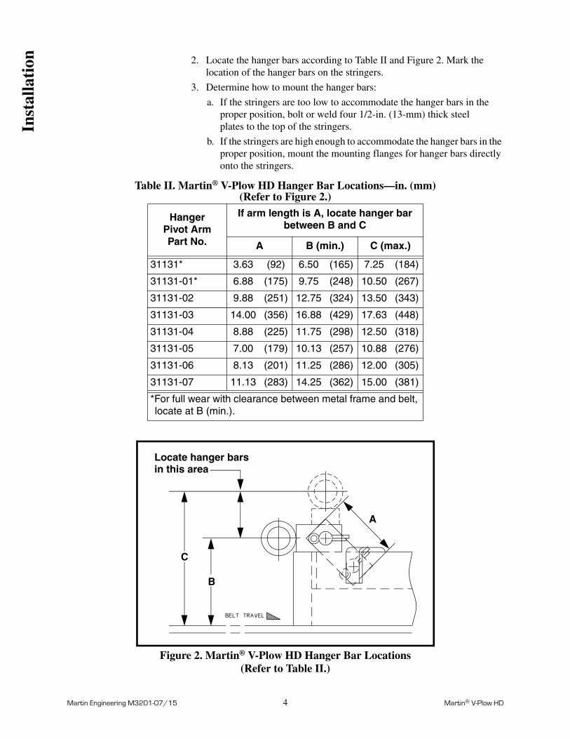
2. Locate the hanger bars according to Table II and Figure 2. Mark the location of the hanger bars on the stringers.
3. Determine how to mount the hanger bars:
a. If the stringers are too low to accommodate the hanger bars in the proper position, bolt or weld four 1/2-in. (13-mm) thick steel plates to the top of the stringers.
b. If the stringers are high enough to accommodate the hanger bars in the proper position, mount the mounting flanges for hanger bars directly onto the stringers.
Table II. Martin® V-Plow HD Hanger Bar Locations—in. (mm)(Refer to Figure 2.)
Figure 2. Martin® V-Plow HD Hanger Bar Locations(Refer to Table II.)
HangerPivot ArmPart No.
If arm length is A, locate hanger bar between B and C
A B (min.) C (max.)
31131* 3.63 (92) 6.50 (165) 7.25 (184)
31131-01* 6.88 (175) 9.75 (248) 10.50 (267)
31131-02 9.88 (251) 12.75 (324) 13.50 (343)
31131-03 14.00 (356) 16.88 (429) 17.63 (448)
31131-04 8.88 (225) 11.75 (298) 12.50 (318)
31131-05 7.00 (179) 10.13 (257) 10.88 (276)
31131-06 8.13 (201) 11.25 (286) 12.00 (305)
31131-07 11.13 (283) 14.25 (362) 15.00 (381)
*For full wear with clearance between metal frame and belt, locate at B (min.).
Locate hanger barsin this area
B
C
A
Inst
alla
tion

Martin Engineering M3201-07/15 5 Martin® V-Plow HD
Figure 3. Distance Between Hanger Bars
4. Use a mounting flange as a template to mark the location of mounting holes on the stringers or steel plates on both sides of the belt for each hanger bar.
NOTEFor easier maintenance, Martin Engineering recommends bolting rather than welding mounting flanges to stringers or steel plates.
5. Bolt or weld the mounting flanges to the stringers or steel plates as follows:
a. If bolting the mounting plates to stringers or steel plates, do the following:
(1) Drill or cut four 2-1/2-in. (63-mm) holes for the two hanger bars.
(2) Drill or cut four 9/16-in. (14-mm) holes for the mounting screws for each mounting flange.
(3) Remove burrs and sharp edges.
(4) Install each mounting flange onto the stringer or steel plate with four hex head cap screws, flat washers, compression washers, and hex nuts.
b. If welding the mounting plates to stringers or steel plates, do the following:
(1) Drill or cut four 2-1/2-in. (63-mm) holes for the two hanger bars.
(2) Position each mounting flange onto the stringer or steel plate.
(3) Weld each mounting flange onto the stringer or steel plate. Make a continuous weld around the entire mounting flange.
Assembly Part Number
Dim. A
31106-18XX 3.13 (79)31106-24XX 6.50 (165)31106-30XX 8.00 (203)31106-36XX 11.00 (279)31106-42XX 14.00 (356)31106-48XX 17.00 (432)31106-54XX 20.00 (508)31106-60XX 23.00 (584)31106-72XX 29.00 (737)31106-84XX 35.00 (889)31106-96XX 41.00 (1041)
Dim. A Inst
alla
tion

Martin Engineering M3201-07/15 6 Martin® V-Plow HD
Figure 4. Installing Martin® V-Plow HD
6. Insert the hanger bars (C, Figure 1) through the mounting holes. Attach each hanger pivot arm (G) to the hanger bar with a clevis pin (A, Figure 4) and cotter pin (B).
7. Center the blade on the belt. Slide a mounting hub (H, Figure 1) onto both ends of each hanger bar, and up against the mounting flanges. Tighten the two set screws (J) in each mounting hub.
CAUTION!
Restraining cables must be installed to prevent the plow from being carried into the pulley if the mount brackets should fail. Failure to install restraining cables could severely damage the plow, pulley, and belt. Do not install restraining cables on stringers that are between the plow and tail pulley.
8. Attach a restraining cable (C, Figure 4) to the conveyor stringers far enough from the tail pulley. Make sure v-plow is located according to chart in Figure 1. Leave no more than 2 in. (51 mm) of slack in cable.
A.B.
Clevis pin (6)Cotter pin (6)
AB
C
C. Restraining cableD.E.F.
Frame weldmentSquare head set screwC-clamp
D
E
F
X
Inst
alla
tion

Martin Engineering M3201-07/15 7 Martin® V-Plow HD
After Installing V-Plow
IMPORTANTRead entire section before beginning work.
1. Thoroughly wipe the outside chute wall clean above the v-plow on the operator side of the chute. Place a Conveyor Products Warning Label (P/N 23395) and a Flying Objects Warning Label (P/N 38227) on the chute wall visible to the belt operator.
2. Additional safety labels are available from CEMA. For more information regarding CEMA safety labels visit www.cemanet.org.
WARNING!
Failure to remove tools from installation area and conveyor belt before turning on energy source can cause serious injury to personnel and damage to belt.
3. Remove all tools and the fire-retardant cover from the installation area and conveyor belt.
DANGER!
Do not touch or go near conveyor belt or conveyor accessories when conveyor belt is running. Body or clothing can get caught and pull body into conveyor belt, causing severe injury or death.
4. Turn on the conveyor belt for 1 hour.
DANGER!
Before installing, servicing, or adjusting conveyor equipment, turn off and lockout / tagout / blockout / testout all energy sources to the conveyor and conveyor accessories according to ANSI standards. Failure to do so could result in serious injury or death.
5. After 1 hour of operation, turn off and lockout / tagout / blockout / testout energy source according to ANSI standards (see “References”).
6. Make sure all fasteners are tight. Tighten if necessary.
7. Inspect the V-Plow for wear. (A small amount of “break-in” wear may be found. This will stop once the blade wears to the conveyor belt contour.)
8. Make sure the plow is pushing material off the edge of the belt efficiently, leaving minimal material on the belt.
9. Repeat step 2.
Aft
er I
nsta
llati
on

Martin Engineering M3201-07/15 8 Martin® V-Plow HD
Monthly Maintenance
IMPORTANTRead entire section before beginning work.
DANGER!
Before installing, servicing, or adjusting conveyor equipment, turn off and lockout / tagout / blockout / testout all energy sources to the conveyor and conveyor accessories according to ANSI standards. Failure to do so could result in serious injury or death.
1. Turn off and lockout / tagout / blockout / testout energy source according to ANSI standards (see “References”).
2. Make sure all fasteners are tight. Tighten if necessary.
3. Check the cleaning edge for wear. If it is worn almost to the frame weldment (D, Figure 4), replace as follows:
a. Remove the square head set screws (E) and C-clamps (F) holding the cleaning edge against the frame weldment.
b. Remove the old cleaning edge.
c. Install a new cleaning edge and secure with C-clamps and square head set screws.
4. Check the restraining cable for wear. Make sure the cable is securely attached to the stringers.
5. Wipe all labels clean. If the labels are not readable, contact Martin Engineering or your representative for replacements.
WARNING!
Failure to remove tools from installation area and conveyor belt before turning on energy source can cause serious injury to personnel and damage to belt.
6. Remove all tools from the maintenance area.
DANGER!
Do not touch or go near conveyor belt or conveyor accessories when conveyor belt is running. Body or clothing can get caught and pull body into conveyor belt, causing severe injury or death.
7. Start the conveyor belt.
Mai
nten
ance

Martin Engineering M3201-07/15 9 Martin® V-Plow HD
Part Numbers
This section provides product names and corresponding part numbers for the Martin® V-Plow HD and related equipment. Please reference the part numbers when ordering parts.
Martin® V-Plow HD Assembly
For belts 18 to 48 in. wide: P/N 31106-XXXX. See Figure 5.
For belts 54 to 96 in. wide: P/N 31106-XXXX. See Figure 6. Par
t N
umbe
rs

Martin Engineering M3201-07/15 10 Martin® V-Plow HD
Figure 5. Martin® V-Plow HD Assembly, P/N 31106-XXXX* (18 - 48-in. [400 - 1400-mm] belts)
*First XX indicates belt width (18 through 48 in.); third X indicates urethane or rubber blade; fourth X indicates special pivot arm heights (blank indicates standard height); last XX indicates material for urethane blades. **XX indicates belt width in inches.
Item Description Part No. Qty
1 Frame Weldment 31135-XX 1
2 Blade Urethane Table VII Table IV
3 Blade 800 Nitrile Rubber 100066 Table IV
4 C-Clamp 31132 Table III
5 Screw SHS 1/2-13NC x 1 22763-03 Table III
6 Pin Cotter 16578 6
7 Pin Clevis 29066 6
8 Bar Front Hanger 31136-XX 1
9 Bar Back Hanger 31133-XX 1
10 Hub Mounting 16845 4
11 Clip Cable 23481 4
12 Arm Hanger Pivot Table VIII 6
13 Lanyard 100107 Table III
14 (NS) Conveyor Products Warning Label 23395 2
15 (NS) Operator’s Manual M3201 1
16 (NS) Flange Mounting Table III 4
17 (NS) Mounting Hardware Kit Table III 1
18 (NS) Martin Products Label 32238 2
19 (NS) Flying Objects Warning Label 38227 2
4
5
2,31
7 6
1311
98
16
12
10
Par
t N
umbe
rs

Martin Engineering M3201-07/15 11 Martin® V-Plow HD
Table III. Martin® V-Plow HD Item Quantities and Part Numbers
Table IV. Martin® V-Plow HD Blade Quantities
AssemblyPart No.
Items 4 & 5 Qty
Item 13Qty
Item 8Part No.
Item 16Part No.
Item 17Part No.
31106-18XXXX 4 5’ 0” 31136-24 30208 38735-1
31106-24XXXX 4 5’ 0” 31136-24 16628 38735
31106-30XXXX 6 5’ 8” 31136-36 16628 38735
31106-36XXXX 6 5’ 8” 31136-36 16628 38735
31106-42XXXX 8 6’ 10” 31136-48 16628 38735
31106-48XXXX 8 6’ 10” 31136-48 16628 38735
AssemblyPart No.
Item 2Qty
Item 3Qty
31106-18RX 0 2.25
31106-18UXXX 1 0
31106-24RX 0 2.96
31106-24UXXX 1 0
31106-30RX 0 3.67
31106-30UXXX 1 0
31106-36RX 0 4.37
31106-36UXXX 1 0
31106-42RX 0 5.08
31106-42UXXX 1 0
31106-48RX 0 5.79
31106-48UXXX 1 0
Par
t N
umbe
rs

Martin Engineering M3201-07/15 12 Martin® V-Plow HD
Figure 6. Martin® V-Plow HD Assembly, P/N 31106-XXXXXX* (54 - 96-in. [1400 - 2400-mm] belts)
*First XX indicates belt width (54 through 96 in.); third X indicates urethane or rubber blade; fourth X indicates special pivot arm heights (blank indicates standard height); last XX indicates material for urethane blades. **XX indicates belt width in inches.
Item Description Part No. Qty
1 Frame Weldment 31135-XX 1
2 Blade Urethane Table VII Table VI
3 Blade 800 Nitrile Rubber 100066 Table VI
4 C-Clamp 31132 Table V
5 Screw SHS 1/2-13NC x 1 22763-03 Table V
6 Pin Cotter 16578 6
7 Pin Clevis 29066 6
8 Bar Front Hanger 31136-XX 1
9 Bar Back Hanger 31133-XX 1
10 Hub Mounting 16845 4
11 Clip Cable 23481 4
12 Arm Hanger Pivot Table VIII 6
13 Lanyard 100107 Table V
14 Weight 5 lbs Stackable 28817 Table V
15 Screw HHC 1/2-13NC Table V 2
16 Nut Hex 1/2-13NC 11771 2
17 Washer Compression 1/2 11750 2
18 Washer Flat 1/2 31010 2
19 (NS) Conveyor Products Warning Label 23395 2
20 (NS) Operator’s Manual M3201 1
21 (NS) Flange Mounting 16628 4
22 (NS) Mounting Hardware Kit 38735 1
23 (NS) Martin Products Label 32238 2
24 (NS) Flying Objects Warning Label 38227 2
4
5
2,3
1
6 7
11
139
15
14
1617188
21
12
10
Par
t N
umbe
rs

Martin Engineering M3201-07/15 13 Martin® V-Plow HD
Table V. Martin® V-Plow HD Item Quantities and Part Numbers
Table VI. Martin® V-Plow HD Blade Quantities
Assembly Part No.
Items 4 & 5 Qty
Item 13Qty
Item 8Part No.
Item 17Part No.
31106-54XXXX 10 8’ 0” 31136-60 30224
31106-60XXXX 10 8’ 0” 31136-60 30224
31106-66XXXX 12 9’ 2” 31136-72 30224
31106-72XXXX 12 9’ 2” 31136-72 30224
31106-78XXXX 14 9’ 7” 31136-84 M921
31106-84XXXX 14 9’ 7” 31136-84 M921
31106-96XXXX 16 10’ 10” 31136-96 M921
AssemblyPart No.
Item 2Qty
Item 3Qty
31106-54RX 0 6.50
31106-54UXXX 1 0
31106-60RX 0 7.21
31106-60UXXX 1 0
31106-66RX 0 7.92
31106-66UXXX 1 0
31106-72RX 0 8.62
31106-72UXXX 1 0
31106-78RX 0 9.33
31106-78UXXX 1 0
31106-84RX 0 10.04
31106-84UXXX 1 0
31106-96RX 0 11.46
31106-96UXXX 1 0
Par
t N
umbe
rs

Martin Engineering M3201-07/15 14 Martin® V-Plow HD
Table VII. Martin® V-Plow HD Urethane Blade Chart
Table VIII. Martin® V-Plow HD Hanger Pivot Arm Part Numbers
AssemblyPart No.
Item 2Part No.
BladeMaterial
BladeColor
31106-XXXX 31134-XXU 90 Durometer Orange
31106-XXUXGR 31134-XXUGR 95 Durometer Green
31106-XXUXBL 31134-XXUBL 85 Durometer Blue
31106-XXUXBR 31134-XXUBR 85 Durometer Brown
AssemblyPart No.
Pivot ArmPart No.
Pivot Arm Lengthin (mm)
31106-XXX 31131 3.63 (92)
31106-XXX1 31131-01 6.88 (175)
31106-XXX2 31131-02 9.88 (251)
31106-XXX3 31131-03 14.00 (356)
31106-XXX4 31131-04 8.88 (225)
31106-XXX5 31131-05 7.00 (179)
31106-XXX6 31131-06 8.13 (201)
31106-XXX7 31131-07 11.13 (283)
Par
t N
umbe
rs

Martin Engineering M3201-07/15 15 Martin® V-Plow HD
Figure 7. Conveyor Products Warning Label, P/N 23395
MUCHO
WARNINGON
Lock out and/or tag out all energy sources to
Cierre y/o rotule todas las fuentes de energía al
Label P/N 23395
!CUIDADO!
conveyor system and loading system before performing any work on conveyor or conveyoraccessories. Failure to do so could result insevere injury or death.
sistema transportador y al sistema de carga antesde realizar cualquier trabajo sobre el transportadoro sobre los accesorios del transportador. Si nose procede asi, puede resultar en heridas seriaso muerte.
Par
t N
umbe
rs

Martin Engineering M3201-07/15 16 Martin® V-Plow HD
Figure 8. Flying Objects Warning Label, P/N 38227
Par
t N
umbe
rs

Any product, process, or technology described here may be the subject of intellectual property rights reserved by Martin Engineering Company. Trademarks or service marks designated with the ® symbol are registered with the U.S. Patent and Trademark Office and may be proprietary in one or more countries or regions. Other trademarks and service marks belonging to Martin Engineering Company in the United States and/or other countries or regions may be designated with the “TM” and “SM” symbols. Brands, trademarks, and names of other parties, who may or may not be affiliated with, connected to, or endorsed by Martin Engineering Company, are identified wherever possible. Additional information regarding Martin Engineering Company’s intellectual property can be obtained at www.martin-eng.com/trademarks.

Martin Engineering USAOne Martin PlaceNeponset, IL 61345-9766 USA800 544 2947 or 309 852 2384Fax 800 814 1553www.martin-eng.com
Form No. M3201-07/15 © Martin Engineering Company 1998, 2015