mass customization: reuse of topology …wenyaoxu/papers/conference/...mass customization: reuse of...
TRANSCRIPT
Mass Customization: Reuse of TopologyInformation to Accelerate Slicing Process for
Continuous Liquid Interface Production
Hang Ye1, Chi Zhou1∗, and Wenyao Xu2
1Department of Industrial and Systems Engineering2Department of Computer Science and Engineering
University at Buffalo, The State University of New York, Buffalo, NY 14260
Email: [email protected], [email protected], [email protected]
Additive manufacturing (AM), also known as 3D printing,constructs a 3D object in a layer by layer fashion. Compar-ing to traditional manufacturing technologies, it can buildobjects with complex individualized features with little extraeffort. This characteristic endows additive manufacturingwith the potential to realize mass customization. ContinuousLiquid Interface Production (CLIP), a newly emerged Stere-olithography Apparatus (SLA) based AM process, can createa solid object by using video projection as the energy sourceto cure the liquid photo-sensitive polymer resin. This processworks in a continuous fashion, so it can achieve extremelyhigh productivity that is crucial to mass customization. CLIPadopts a great number of images which are corresponding tocross-sectional geometric patterns as input, but this posesa challenge regarding to slice generation. The slice com-putation procedure for a single customized model can takehours to complete, and the time consumption becomes moreprominent in mass customization, which fabricates numer-ous models in the same batch. Based on the observation thatsimilarities exist among most customized products, we pro-posed a new slicing paradigm. This slicing paradigm reusestopology information obtained from the template model forother customized products of the same category, and the ideaof topology information reuse is implemented in three lev-els, including self reuse, intra-model reuse, and inter-modelreuse. Experimental results show that the proposed slicingparadigm can significantly reduce the time consumption onpre-fabrication computation.
Keywords: Mass Customization, Additive Manufacturing,Topology, Slicing, CLIP.
∗Corresponding author. Phone: (716) 645-4706 Fax: (716) 645-3302
1 Introduction
The prevailing “mass production” is an important pro-peller of the rapid development in human material civiliza-tion after the industrial revolution, and it is also a signifi-cant source of the nation’s economic strength in last century.The characterized scale effect from mass production resultsin reduced cost and easiness to obtain a product, so it im-proves quality and sustainability of human life. However, itis also because of the highly developed material civilization,any product could have countless substitutions on the marketsharing similar functions. Customers are no longer satisfiedwith just realizing the basic function, in addition, they wouldprefer to purchase the products that can better meet theirspecific tastes. It is apparent that traditional mass produc-tion is not capable of handling this tremendous diversity incustomer needs. Innovative practitioners are thinking aboutlifting their way to a new paradigm, mass customization, tomeet the ever changing turbulent market environment. Theinitial idea about the principle of “mass customization” canbe traced back to early 1970’s [1], and Davis coined thisphrase in 1987 [2]. According to Tseng and Jiao, mass cus-tomization was defined as “the technologies and systems todeliver goods and services that meet individual customer’sneeds with near mass production efficiency” [3].
However, highly customized products are very challeng-ing to be mass-produced in the traditional way. Both thetangible and intangible costs of making personalized prod-ucts are usually very high, and this is especially apparentfor human-centered products, e.g., tooth aligner, hearing aid,artificial limb etc. Therefore, the business has to wait fortoday’s technology advancement to enable profitable cus-tomization. Over the last 30 years, additive manufacturingemerges as a new type of manufacturing process. It is a col-lection of techniques to fabricate solid objects directly froma three-dimensional (3D) model created in Computer AidedDesign (CAD) without the need for object-specific tooling

and fixtures [4]. In traditional manufacturing process, a com-mercialized setup can only handle very limited types of prod-ucts if not only one. Even a tiny local feature change fromthe product may lead to a re-design of the whole setup andprocess. Comparing to traditional manufacturing techniques,an important advantage of AM is that it provides “complex-ity for free” [4]. This property offers high flexibility andshortened product life cycle without extra penalty, thus AMhas the potential to be the technical foundation for profitablecustomization.
Some innovative companies have already embraced thenew mass customization paradigm by taking advantage of theunique design freedom offered by AM process. These com-panies spread in various fields, such as medical, aerospace,automotive, and consumer industries [5]. The Walter ReedNational Military Medical Center utilizes AM to producecustomized cranial plates and cutting guides for bone grafts[6]. Several automotive manufacturers, such as Ford andBMW, offer their customers an option to select additivelymanufactured features, including trims and inlays [7]. Com-puter game peripheral is another field where AM process hasbeen adopted. The FigurePrints allows the players of World-of-Warcraft to purchase miniature models of their game char-acters which are built by full color AM [5]. Align Tech-nology, which is running business of providing orthodontictreatment devices, utilizes reverse engineering and AM tech-nology to progressively fabricate transparent dental bracesthat are worn on patients’ teeth to gradually move the mis-placed teeth to the desired positions. The orthodontic treat-ment usually lasts for 2 to 3 years, and during each treat-ment period, a patient receives a pair of new aligners every2 weeks. It is reported that the company run the 3D printer(SLA-7000) 24 hours and produces 40,000 unique alignersper day. Therefore, the handling of many different complexshapes in a tight time frame is a big challenge, and requiresmass customization to be involved. Siemens Hearing Instru-ments Inc. applies Selective Laser Sintering (SLS) basedAM process to fabricate shells of hearing aids, and more than10 million customized hearing aid shells have been createdby AM. The company reports that the customer satisfactionhas been improved after it started to offer better-fitted prod-ucts [8]. Several applications that utilize AM technology toenable mass production of highly customized products areshown in Fig.1.
Fig. 1. Mass Customization Applications based on Additive Man-ufacturing [9]: (a) dental industry, (b) medical industry, (c) jewelryindustry, (d) entertainment industry.
AM technology holds the advantages of affordabilityand customizability, but the key challenge in applying it for
mass customization is how to reduce the product lead time[4]. The time of building a 3D object is comprised of twocomponents: the pre-fabrication computation and the man-ufacturing process. The later used to be the bottleneck ofAM. Although this technology is also named as “rapid pro-totyping”, it was not that fast before. For example, a sin-gle hearing aid shell used to take tens of minutes or evenhours to be created. Comparing to this, the time spent onpre-fabrication computation seemed trivial as it usually takesonly a few minutes or even seconds. However, recentlyTumbleston et al. proposed a Continuous Liquid InterfaceProduction (CLIP) approach to continuously grow an objectfrom a vat of liquid material rather than printing them layer-by-layer [10]. This revolutionary breakthrough has provento be 25-100 times faster than what is available on the mar-ket today. As a matter of fact, complex products can be fin-ished in minutes instead of hours by CLIP nowadays. Onone hand, the emergence of CLIP provides us with fullyready hardware support to apply AM on mass customiza-tion. But on the other hand, it poses a great challenge for thepre-fabrication computation, and makes it the bottleneck thathinders the realization of industrial revolution introduced byAM. In fact, the continuous mode is an indication of usingextremely small layer thickness or extremely great numberof layers. Adopting this extremely thin layer increases theinput size of pre-fabrication computation dramatically, andthe computation cost also rockets up drastically.
In this study, we proposed a new slicing paradigm basedon the observation that similarities exist among most cus-tomized products from the same category. The proposedslicing paradigm reuses topology information obtained fromthe template model for the same category of customizedproducts, and the idea of topology information reuse is im-plemented in three levels, including self reuse, intra-modelreuse, and inter-model reuse. The remainder of the paper isorganized as follows: In Sec.2, we overviewed the existingslicing method, the similarity among customized products,and the property of STL file. We also briefly described theproposed slicing paradigm in this section. In Sec.3, we pro-posed an improved slicing algorithm which took advantageof topological continuity. Intra-model topology informationreuse was presented in Sec.4. And in Sec.5, we introducedinter-model topology information reuse which was capableof handling local feature add-on and/or removal. The con-clusion and discussion were presented in Sec.6.
2 Background2.1 Existing Slicing Algorithm
Many novel AM processes incorporate different tech-nologies, such as laser, nozzle, jetting, electron beam, andcutter etc. [4, 11, 12]. From the late 1980s, some of theabove have been successfully commercialized [13], e.g.,StreoLithography Apparatus (SLA), Selective Laser Sinter-ing (SLS), Fused Deposition Modeling (FDM), and 3D print-ing. All those techniques were developed based on the lay-ered based additive principle [14]. Almost all AM techniquesbuild the 3D object in a layer by layer fashion, so they take

the cross-sectional profile derived from the 3D CAD modelas the input, and this information is used to direct the energyor material deposition. The common practice for obtainingthe cross-sectional information is intersecting the 3D modelwith a number of horizontal planes. A de facto standard in-put for additive manufacturing process is the STL (STere-oLithography) format, which is also known as Standard Tes-sellation Language. STL file format was originally devel-oped for the stereolithography CAD software, and nowadaysmost CAD system, such as AutoDesk, Catia, ProEengineer,and SolidWorks, can export the native CAD format as STLfile. STL file is essentially a triangulated surface representa-tion for a given object. It uses a set of orientable triangularfacets to approximate the shape of the object. Each trianglefacet is defined by three vertices which are saved accordingto the right-hand rule, and its orientation is represented by aunit normal.
Originally, the intersection, if exists, between a 3D ob-ject and a plane should be a 2D planar area (a single point ora line/curve can be viewed as the degeneration of a 2D planararea). Because of the adoption of STL format, which repre-sents a 2D surface embedded in 3D space, the intersectionbecomes a 1D object embedded in 2D space. This 1D objectis the boundary/contour of the previously mentioned 2D pla-nar area, and it consists of a set of segments, each of whichis defined by two end points. For a manifold mesh model,this 1D object must be one or more simple closed polygonswith consistent orientations. The orientation of the polygonis used to indicate whether the area it encloses is solid orhollow. The process to obtain these intersections is usuallycalled “slicing”.
The calculation of end point coordinates for segment isstraightforward. We traverse all triangle facets, and for eachtriangle facet we evaluate whether or not it intersects withcurrent slicing plane (Z = Zk). This can be done by simplychecking the minimal vertical coordinate (Zmin) and maximalvertical coordinate (Zmax) of three vertices from the triangle.If Zmin < Zk and Zmax > Zk, the triangle will intersect withcurrent slicing plane. Then each end point can be calculatedby using Eqn.(1), where V1(X1,Y1,Z1) and V2(X2,Y2,Z2) aretwo end points of the intersected edge from the triangle. Theoutcome of this computation is a set of unordered segments,and the connectivity/adjacency among these segments hasnot been explored yet. For most AM setup, it is neces-sary to know the connectivity for tool path planning, e.g.,polygon offsetting, G-code generation etc., so we should ar-range these segments in the right order to form one or moreclosed polygons. Closest point method [4] and marching al-gorithm [15] are two classic slicing algorithms. The formerone calculates the coordinates of intersection points first, andretrieves the connectivity afterwards. The later one exploresthe topology by sorting first, and then calculates the intersec-tion coordinates in order according to the adjacency.
X = (Zk−Z1)×(X2−X1)Z2−Z1
+X1
Y = (Zk−Z1)×(Y2−Y1)Z2−Z1
+Y1
Z = Zk
(1)
At a specific layer, assume there exists n triangle facetsintersected with current slicing plane. The closest pointmethod calculates coordinates for 2n end points from n seg-ments, and the time complexity is O(n). However, in orderto determine which point is connected to a given point, thedistances between this point and all points from un-exploredsegments have to be computed, and this process increasesthe time complexity to O(n2). In contrast, marching algo-rithm propagates the contour from one triangle to its neigh-bor until getting back to the initial one, so it only calculatescoordinates for n points, and the connectivity is exactly thesame as the sequence of marching. Although marching algo-rithm seems more time-efficient than closest point method, itis necessary to know the adjacency information of the trian-gle facets in advance. This adjacency information does notcome with the STL format model automatically, and its con-struction is also time-consuming.
2.2 Similarity among Customized Models and MeshProperty
AM process can construct 3D objects with very com-plex geometric features, therefore, input models can be arbi-trary. As mass customization intends to fabricate individual-ized products with near mass production efficiency, numer-ous models with distinct features present a huge challenge tothe pre-fabrication computation. Although some models arederived from the same template by simple transformations,such as translation, rotation, scaling etc., they still need to beprocessed separately. Fortunately, an important observationis that customized models from the same category usuallyshare the characteristics of high similarity, and this high sim-ilarity exists in both geometry and topology. In order to workproperly, the topological similarity among customized func-tional products is especially prominent. For example, theartificial human heart implant, as shown in Fig.2, needs tohave left atrium, right atrium, left ventricle, right ventricle,veins, and arteries connected properly, and have them iso-lated from one another if necessary. In other words, all hu-man heart implants have to be homeomorphic, although theymay have different customized sizes for some local features.Fig.3 shows another example of two aligners from the samecustomer but for different phases. Those two aligner mod-els are homeomorphic and share 99% similarity in geometry.This high similarity has already been utilized in the prod-uct design, e.g., two different models can be derived fromthe same template by local modification and/or deformation.However, the existing pre-fabrication paradigm treats eachmodel independently, and each model needs to go through

every single step separately, e.g., slicing, tool path planningetc.
Fig. 2. Artificial Heart Implant. The left is the total artificial heart,and the right is human heart [16].
Fig. 3. Two tooth aligner models share the same topology and 99%similarity in geometry. The left is for Phase 0-30 days, and the rightis for Phase 31-90 days.
STL file, as the de facto file format for AM, is the sim-plest polygonal mesh. It consists of three types of mesh ele-ments: vertices, edges and faces [17]. The information to de-scribe the mesh property includes mesh topology and meshgeometry. The mesh topology describes the incidence re-lations among mesh elements [17], such as for each vertexthe incident edges, and for each edge the incident triangularfacets. The mesh geometry describes the position (coordi-nate) of each vertex. It is noteworthy that two models withthe same mesh topology but different mesh geometries canbe different, and two models with the same mesh geome-try but different topologies can be totally different as well.Fig.4(a) shows two different models share the same meshgeometry but are different in mesh topology, and Fig.4(b)shows two different models have the mesh topology in com-mon but are different in mesh geometry. With both meshtopology and mesh geometry the mesh can be unambigu-ously defined.
In STL file each triangular facet is defined by three ver-tices which are saved according to the right-hand rule, andits orientation is represented by a unit normal. Each facet isrepresented as follows:
facet normal N.X N.Y N.Zouter loop
vertex V0.X V0.Y V0.Z
Fig. 4. Mesh Topology and Mesh Geometry: (a) meshes with samegeometry but different topologies, (b) meshes with same topology butdifferent geometries.
vertex V1.X V1.Y V1.Z
vertex V2.X V2.Y V2.Z
endloopendfacet
For efficient rendering purpose, saving each facet in this for-mat can make face enumeration very simple. However, theconnectivity/adjacency is implicit which is undesirable forgeometric algorithms. As mentioned in [18], explicit meshconnectivity will make many geometric algorithms mucheasier to be implemented. Inspired by this, if we can makemesh topology of a single product more predictable by tak-ing advantages of piecewise continuity and the high similar-ity among customized products, the pre-fabrication compu-tation of this product can be more efficient.
2.3 Proposed MethodIn this study, we assume there exists a template mesh
model, and customized models can be derived by modify-ing the template. Because of the high similarity among cus-tomized products, this customized modification can at leastpersist a large portion of the mesh connectivity from thetemplate. With the same mesh connectivity, the customizedproduct is guaranteed to be homeomorphic to the templatewhich is crucial to proper functioning. Individualized shapecan be achieved by modifying the mesh geometry, as shownin Fig.4(b), and this kind of modification is already availablein some softwares, such as Maya, MeshMixer, and Mag-ics. In order to make mesh topology more predictable, wefirst explore the mesh connectivity of the template. Duringthis exploration, piecewise continuity is utilized to reducethe redundant computation. The explored template meshconnectivity will be reused for customized products as theyhave the mesh topology in common. For local feature add-on/removal, we will take care of this local feature indepen-dently, so the topology inherited from the template can keepintact and be reused in future.

3 Self Topology Information ReuseIn this section, the idea of topology information reuse
will be incorporated in a single model by utilizing piecewisecontinuity in mesh connectivity. The classic closest pointmethod is implemented in two steps: 1) calculating inter-section coordinate; and 2) connecting each segment in theright order. The second step is based on the observation thatthe closest point to a given point is the point itself, and theflow chart of this step is shown in Fig.5 [4, 19]. It is thesecond step that dominates the time complexity, and at eachlayer the connectivity of each segment is explored separately.Because each segment is the intersection between the slic-ing plane and a triangular facet, two segments are connectedif and only if their incident triangular facets are adjacent inspace. Therefore, if both of the two adjacent triangular facetscross more than one layers (the edge shared by both facetscrosses more than one layers), the connectivity among theircorresponding segments will persist at all crossed layers.
Fig. 5. Flow Chart for Connecting Segments in Order
An example is shown in Fig.6. Triangular facet Tp andTq have an edge in common, both facets cross ith, i+ 1th,and i + 2th layer, and the corresponding segments Li
p andLi
q, Li+1p and Li+1
q , Li+2p and Li+2
q are connected. The clos-est point method does not utilize this piecewise continuity inmesh connectivity, and conducts idle computations.
The idea of self topology information reuse takes advan-tage of this piecewise continuity in mesh connectivity, andexplores the adjacency between two triangular facets onlyonce. The explored necessary facet adjacency informationis stored in a table, and in later layer if two segments areincident with the same facet pair, they will be connected au-tomatically. Using Fig.6 as an example, if we slice the modelfrom the bottom to the top, the adjacency between Tp and Tqis explored at layer i. At layer i+1, these two facets still getinvolved, and we can march from Li+1
p to Li+1q (or from Li+1
q
to Li+1q ) directly without computing the distances between
the tail of Li+1p (or Li+1
q ) and all other segments on this layer.Since in a manifold mesh model each triangular facet
Fig. 6. Piecewise Continuity in Mesh Connectivity
has three edge-connected neighbors, a t×3 matrix is createdto save the adjacency information, where t is the total num-ber of facets from the model. Each row is corresponding toa facet, and each entry saves the neighboring facet of a givenfacet. For instance, the value of the entry [i, j] (for 0≤ j≤ 2)being k means the jth neighbor of facet Ti is facet Tk. It is ap-parent that the adjacency between two facets is commutative,therefore, the value of the entry [k, l] (for 0≤ l ≤ 2) must bei. For a given triangular facet, we save the adjacency accord-ing to the vertex sequence. Assuming three vertices from aspecific facet are V0, V1 and V2, the neighboring facet whichis opposite to V0 is saved at the first entry, the facet oppositeto V1 is saved at the second entry, and that is opposite to V2is saved at the third entry. Fig.7 shows an example.
Fig. 7. Neighbor Numbering of A Given Triangular Facet
Initially, all entries of the adjacency table are set as -1. At a specific layer, we start from a facet and march fromone facet to another according to the known adjacency untilarriving at a facet with -1 value in the entry corresponding tothe neighbor in marching direction. This marching results ina polyline instead of a segment, and the polyline consists ofone or more connected segments. Fig.8 shows the flow chartof polyline computation.
When all polylines are generated, we only need to inves-tigate the connectivity among polylines by the same idea ofthe closest point method, and the outcome of this investiga-tion will be used to update adjacency matrix afterwards. Theflow chart of this process is shown in Fig.9. Comparing toFig.5, there are only three differences:
1. In this process we investigate the connectivity amongpolylines rather than segments;

Fig. 8. Flow Chart for Computing the Polylines
2. The distance between the head and tail from the samepolyline needs to be compared as well, because it is pos-sible that a single polyline is a closed polygonal contour;
3. The adjacency table is updated according to the mini-mum distance check.
Fig. 9. Flow Chart for Connecting Polylines in Order
Fig.10 shows the intersection between a model and theith slicing plane, and two contours, L1L2L6L8L11L10L3 andL4L7L9L5, are included. The area enclosed by the interiorcontour is hollow, and the area nested between the interiorcontour and the exterior contour is solid. Assume that from
the calculation for the previous layers, the connectivities ofL1L2L6, L4L7L9L5, L11L10L3 are already known, and the in-cident facet of L8 just starts to get intersected with currentslicing plane. After traversing all facets, four polylines willbe generated, and the details are shown in Table 1 (Assumethe index of a facet is identical to the segment which is in-cident to this facet. i.e., Segment Li is incident to triangularfacet Ti). When we finish this layer, the connectivity betweenP1 and P2, P2 and P4, P3 and itself, P4 and P1 can be deter-mined. The adjacency table needs to be upgraded accord-ingly and Table 2 shows the adjacency before and after thisupdate.
Fig. 10. An Example of Self Topology Information Reuse
Table 1. Polyline Information
Polyline Member Segment Head Tail
P1 L1, L2, L6 T1 T6
P2 L8 T8 T8
P3 L4, L7, L9, L5 T4 T5
P4 L11, L10, L3 T11 T3
Typical layer thickness used by existing AM processesis usually between 50 µm and 100 µm, but as a continuousAM process, CLIP can have a layer thickness as small as1 µm [10]. After adopting such a tiny layer thickness, onone hand, the possiblity that the same facet adjacency infor-mation can be reused for many layers is high; on the otherhand, the effect of reusing this adjacency information is sig-nificant comparing to the closest point method. Three mod-els, tooth aligner (Fig.11(a)), hearing aid (Fig.11(c)) and ver-tebral column (Fig.11(e)), are selected as test cases to gothrough both the classic closest point method and the pro-posed slicing method with topology reuse. These models arealso typical human-centered products which have great de-mands for mass customization. The test environment is: 64bit Windows 10 Pro system laptop with Intel(R) Core(TM)i7-4600U, CPU @ 2.10GHz 2.69 GHz and 8GB RAM, andthe layer thickness is set as 1 µm. The results are shown inTable 3. It is apparent that by reusing the topology infor-
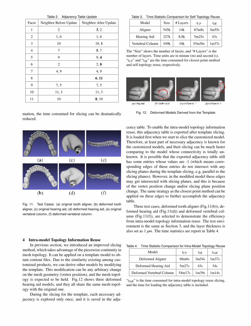
Table 2. Adjacency Table Update
Facet Neighbor Before Update Neighbor After Update
1 2 3, 2
2 1, 6 1, 6
3 10 10, 1
4 7 5, 7
5 9 9, 4
6 2 2, 8
7 4, 9 4, 9
8 6, 11
9 7, 5 7, 5
10 11, 3 11, 3
11 10 8, 10
mation, the time consumed for slicing can be dramaticallyreduced.
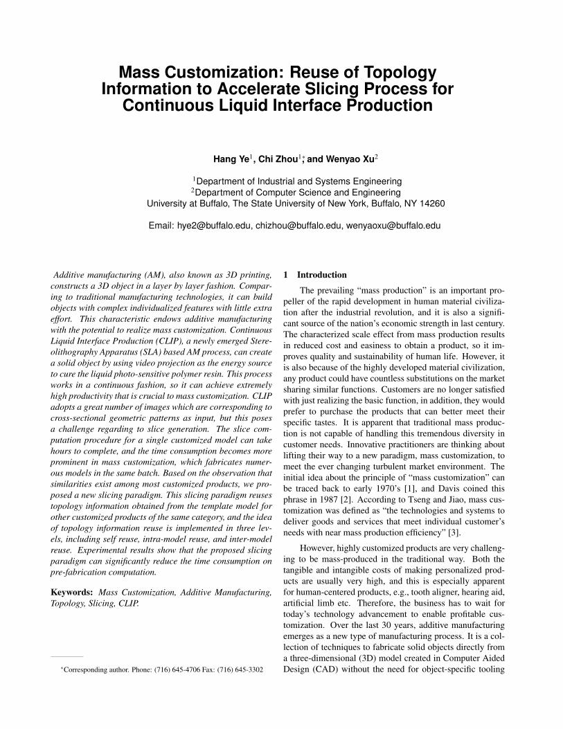
Fig. 11. Test Cases: (a) original tooth aligner, (b) deformed toothaligner, (c) original hearing aid, (d) deformed hearing aid, (e) originalvertebral column, (f) deformed vertebral column.
4 Intra-model Topology Information ReuseIn previous section, we introduced an improved slicing
method, which takes advantage of the piecewise continuity inmesh topology. It can be applied on a template model to ob-tain contour files. Due to the similarity existing among cus-tomized products, we can derive other models by modifyingthe template. This modification can be any arbitrary changeon the mesh geometry (vertex position), and the mesh topol-ogy is expected to be held. Fig.12 shows three deformedhearing aid models, and they all share the same mesh topol-ogy with the original one.
During the slicing for the template, each necessary ad-jacency is explored only once, and it is saved in the adja-
Table 3. Time Statistic Comparison for Self Topology Reuse
Model Size # Layers tCP tSR
Aligner 545k 14k 67m8s 3m55s
Hearing Aid 327k 8.8k 5m25s 43s
Vertebral Column 549k 10k 55m56s 1m37s
The “Size” shows the number of facets, and “# Layers” is thenumber of layers. Time units are in minute (m) and second (s).“tCP” and “tSR” are the time consumed for closest point methodand self topology reuse, respectively.
Fig. 12. Deformed Models Derived from the Template
cency table. To enable the intra-model topology informationreuse, this adjacency table is exported after template slicing.It is loaded first when we start to slice the customized model.Therefore, at least part of necessary adjacency is known forthe customized models, and their slicing can be much fastercomparing to the model whose connectivity is totally un-known. It is possible that the exported adjacency table stillhas some entries whose values are -1 (which means corre-sponding edges of these entries do not intersect with anyslicing planes during the template slicing, e.g, parallel to theslicing planes). However, in the modified model these edgesmay get intersected with slicing planes, and this is becauseof the vertex position change and/or slicing plane positionchange. The same strategy as the closest point method can beapplied on these edges to further accomplish the adjacencytable.
Three test cases, deformed tooth aligner (Fig.11(b)), de-formed hearing aid (Fig.11(d)) and deformed vertebral col-umn (Fig.11(f)), are selected to demonstrate the efficiencyfrom intra-model topology information reuse. The test envi-ronment is the same as Section 3, and the layer thickness isalso set as 1 µm. The time statistics are report in Table 4.
Table 4. Time Statistic Comparison for Intra-Model Topology Reuse
Model tCP tSR tIAR
Deformed Aligner 68m6s 3m54s 1m37s
Deformed Hearing Aid 5m27s 43s 34s
Deformed Vertebral Column 54m17s 1m39s 1m14s
“tIAR” is the time consumed for intra-model topology reuse slicing,and the time for loading the adjacency table is included.

5 Inter-model Topology Information ReuseSometimes modifying the template model only by
changing the vertex position cannot generate desired cus-tomized feature, and local feature add-on and/or removalmight be necessary. For example, a customer or a manu-facturer may want to add a unique monogram on a specificcustomized product to differentiate this product from oth-ers. The monogram can be numbers, characters, or even QRcode, and it is not easy to be achieved by changing the meshgeometry only.
Adding a feature to a mesh model can be accomplishedby Boolean union, and some commercial softwares, such asMagics, can do this without any difficulty. The union oper-ation merges two manifold mesh models into one, and theresultant model has to be manifold as well. During this pro-cess, the facets at or near the conjunction have to be merged,cut, or deleted. For mass customization, the impacted facetsmay only be a small part of the whole model, but the originalmesh topology has been changed. If the impacted facets canbe identified, we can edit the adjacency table accordingly tomake it still reuseable. Unfortunately, this topology changeoccurred during the modification is not traceable for mostmesh processing softwares.
In order to reuse the template topology, the add-on fea-ture is saved as a separate manifold mesh model, and itis placed at the designated position relative to the templatemodel. In the following slicing process, the template and theadd-on feature are sliced independently, therefore, the topol-ogy information for the template can still be reused. Afterboth parts have been sliced, the contour profiles from bothparts are combined together to convert into binary images.Fig.13 is a hearing aid model with 3D personalized mono-gram, and we use this model as an example to illustrate thedetails.
Fig. 13. Hearing Aid with Monogram: (a) hearing aid model, (b)monogram, (c) resultant model.
For the original hearing aid model (Fig.13(a)), the ad-jacency table derived from template slicing still can be used.Comparing to the hearing aid model, any add-on feature usu-ally has a smaller size in terms of number of facets. Inthis example, the hearing aid model has 327,428 triangles,whereas the monogram only contains 6,932 facets. Alongthis line, whether the connectivity of add-on feature is knownis insignificant. Because the monogram is an add-on feature,the polygonal area enclosed by the contour of template andthat enclosed by the contour of monogram must have someoverlap (That is to say they have to at least share some seg-
ments in order to be connected to each other). This overlapresults in intersection of the contours, and leads to invalidloops. Because CLIP is a mask projection based SLA pro-cess, we can skip the process of invalid loop identificationand removal, which is usually required in planar polygonoffsetting problem, to generate a valid image directly fromcontour with invalid loops.
In this paper, the concept of winding number [20] isused to generate aforementioned valid images. If we adoptthe convention that the exterior contour is oriented counter-clockwise (CCW) and the interior contour oriented clock-wise (CW), the winding number is defined as following [20]:Definition 1: Let P⊂ R2 be a set of oriented polygonal con-tours, q ⊂ R2 be a point, and r ⊂ R2 be any ray from q toinfinity that intersects no vertex of P. The winding numberω(r,P) of r with respect to P is:
ω(r,P) = ∑ei∈P
Ψ(r,ei)
where for each edge ei, Ψ(r,ei) is defined as follows:
Ψ(r,ei) =
0 if r does not intersect ei;1 if ei crosses r in CCW as view from q;−1 if ei crosses r in CW as view from q.
In order to determine whether a single connected region issolid or hollow, positive winding rule is selected. If thewinding number for this region is positive, it is classifiedas solid, and the pixels on the image it covers are set asforeground. Otherwise, the region is identified as hollow,and its corresponding pixels on the image are set as back-ground. Fig.14(a) represents the contour at a specific heightfor the hearing aid model with monogram, and the calcu-lated winding number is shown in Fig.14(b). Fig.14(c) is thebinary image after conversion which can be used for CLIPdirectly. It is noteworthy that this method is also capable ofhandling feature removal, and the principal idea is the sameas Boolean difference. In this application, the orientationof the contour from removing feature needs to be reversed.Fig.14(e)-(h) shows an example for feature removal.
6 Conclusion and DiscussionIn this paper, we embraced the idea of reuse in the
computational field for additive manufacturing. The emerg-ing CLIP technology can dramatically reduce the fabrica-tion time, and now the pre-fabrication computation becomesthe bottleneck. By taking advantage of the high similarityexisting among customized products, we proposed reusingthe topology information to accelerate slicing process. Thisreuse was implemented in three levels, including self reuse,intra-model reuse, and inter-model reuse. Self reuse is basedon the piecewise continuity in mesh connectivity, and itreuses the topology information explored from the calcula-tion for previous layers. This improved slicing algorithmdoes not aim at decreasing the order of asymptotic time com-plexity, instead it is trying to reduce the size of input by

Fig. 14. Hearing Aid with Monogram: (a) contour with feature add-on, (b) winding number for feature add-on, (c) image for feature add-on, (d) zoom-in image for feature add-on; (e) contour with featureremoval, (f) winding number for feature removal, (g) image for featureremoval, (h) zoom-in image for feature removal.
eliminating redundant calculations. Comparing to the clas-sic closest point method, time saving is significant, but thismethod consumes more storage. For a given model anda specific layer thickness, the total number of connectivityneeded to be explored is a constant. If all necessary con-nectivity is known, the asymptotic time complexity is linear.Intra-model reuse utilizes the topology information obtainedfrom template slicing, and expects to attain a near linear timecomplexity. Customized model which is suitable for intra-model reuse can be derived from the template by applyingvertex position change on all three dimensions as long as themesh topology persists. And inter-model reuse was also pro-posed to take care of local feature add-on and removal, whichis also very common in practice. It treats the add-on/removalfeature independently to keep the mesh topology from tem-plate intact, so this information can be reused. In the contour-image conversion, Boolean operations are adopted to rendera valid mask image. Experimental results show that promi-nent time saving can be achieved by adopting the proposedmethod.
AcknowledgementsThe authors are grateful for financial support from Na-
tional Science Foundation (NSF) through CNS-1547167.
References[1] Toffler, A., 1970. Future Shock. Random House, New
York, NY.[2] Davis, S. M., 1987. Future Perfect. Addison-Wesley,
Reading, MA.[3] Salvendy, G., ed. Handbook of Industrial Engineering:
Technology and Operations Management, 3rd ed. JohnWiley & Sons, New York, NY, Chap. 25, pp. 684–687.
[4] Gibson, I., Rosen, D. W., and Stucker, B., 2009. Ad-ditive Manufacturing Technologies: Rapid Prototypingto Direct Digital Manufacturing, 1st ed. Springer, NewYork, NY.
[5] Fogliatto, F., and da Silveira, G., 2010. Mass Cus-tomization: Engineering and Managing Global Oper-ations. Springer Series in Advanced Manufacturing.Springer.
[6] Scott, J., Nayanee Gupta, C. W., Newsome, S.,Wohlers, T., and Caffrey, T., 2012. Additive Manufac-turing: Status and Opportunities. Tech. rep., Scienceand Technology Policy Institute.
[7] Ford, S. L. N., 2014. “Additive manufacturing tech-nology: Potential implications for u.s. manufacturingcompetitiveness”. Journal of International Commerceand Economics.
[8] Froehlich, M., 2013. Insio: A New Standard in CustomInstruments. Tech. rep., Siemens.
[9] Envisiontec, Inc. http://envisiontec.com/.[10] Tumbleston, J. R., Shirvanyants, D., Ermoshkin, N.,
Janusziewicz, R., Johnson, A. R., Kelly, D., Chen, K.,Pinschmidt, R., Rolland, J. P., Ermoshkin, A., Samul-ski, E. T., and Desimone, J. M., 2015. “Continuousliquid interface production of 3d objects”. Science,347(6228), pp. 1349–1352.
[11] Beaman, J. J., Barlow, J. W., Bourell, D. L., Craw-ford, R. H., Marcus, H. L., and McAlea, K. P., 1997.“Solid freeform fabrication: a new direction in manu-facturing”. Kluwer Academic Publishers, Norwell, MA,2061, pp. 25–49.
[12] Jacobs, P. F., 1993. Rapid Prototyping and Manufac-turing: Fundamentals of StereoLithography. McGraw-Hill, New York, NY.
[13] Wohlers, T., 2013. Wohlers Report: Additive Manufac-turing and 3D Printing State of the Industry. Annualworldwide progress report, Wohlers Associates, FortCollins, CO.
[14] Freedman, D. H., 2012. “Layer by layer”. TechnologyReview, 115(1), pp. 50–53.
[15] Rock, S. J., and Wozny, M. J., 1991. “Utilizing topolog-ical information to increase scan vector generation effi-ciency”. In Proceedings of International Solid FreeformFabrication Symposium, pp. 1–9.
[16] SynCardia Systems, Inc. http://www.
syncardia.com/media/multimedia-library-dp1.html.
[17] Armin Iske, E. Q., and Floater, M. S., eds., 1991.Tutorials on Multiresolution in Geometric Modelling.Springer, Berlin, DE, Chap. 12, pp. 319–362.
[18] Shirley, P., and Marschner, S., 2009. Fundamentals ofComputer Graphics, 3rd ed. A K Peters, Natick, MA.
[19] Vatani, M., Rahimi, A. R., Brazandeh, F., and Nezhad,A. S., 2009. “An enhanced slicing algorithm using near-est distance analysis for layer manufacturing”. In Pro-ceedings of World Academy of Science, Engineeringand Technology, Vol. 37, pp. 721–726.
[20] Chen, X., and McMains, S., 2005. “Polygon offset-ting by computing winding numbers”. In Proceedingsof International Design Engineering Technical Con-ferences & Computers and Information Conference(IDETC/CIE 2005), ASME, pp. 1–11. Paper numberDETC2005-85513.