mass production of nanoparticles by high gravity reactive precipitation technology with low cost
TRANSCRIPT

CHINA PARTICUOLOGY Vol. 1, No. 2, 64-69, 2003
MASS PRODUCTION OF NANOPARTICLES BY HIGH GRAVITY REACTIVE PRECIPITATION TECHNOLOGY WITH LOW COST
Jianfeng Chen* and Lei Shao Research Center of the Ministry of Education for High Gravity Engineering and Technology,
College of Chemical Engineering, Beijing University of Chemical Technology, Beijing 100029, P. R. China *Author to whom correspondence should be addressed. E-mail: [email protected]
Abstract Mass production of nanoparticles at low cost has attracted much attention from industrial and academic circles. In this paper, a novel method, the high gravity reactive precipitation (HGRP) technology, of manufacturing CaCO3 nanoparticles, presently scaled-up to an annual capacity of 10,000 tons, is presented. This paper describes the process principle, the process design and experiments on the syntheses of 15-30 nm CaCO3, 30-50 nm SiO2, 20-30 nm TiO2, 20-60 nm ZnO, 20-30 nm ZnS, 30 nm SrCO3, 40-70 nm BaTiO3, stick-like nano BaCO3 as well as nano-fibrillar aluminum hydroxide measuring 1-10 nm in diameter and 50-300 nm in length, using liquid-liquid, gas-liquid and gas-liquid-solid reactant systems. The advantage of using the HGRP technology is illustrated by com-parison to conventional methods. Keywords nanoparticles, high gravity reactive precipitation, rotating packed bed, synthesis
1. Introduction Nanoparticles have found extensive applications in
many fields, such as the environmental, electronic, phar-maceutical, optical, ceramic, chemical and metallurgical industries, as well as the manufacture of pulp and paper. In the past decade, significant research efforts have been directed toward the synthesis, characterization, and proper-ties of nanoparticles. More recently, the concern on mas-sive production of nanoparticles has encouraged research activities in the development of synthesis methods with low-cost and high-volume output. The conventional pre-cipitation process carried out in stirred tanks or column reactors cannot guarantee the quality of the products and control the morphology, size and size distribution of the particles produced. In this paper, a new technology called high gravity reactive precipitation (HGRP) for the mass production of nanoparticles is presented together with an analysis of the key factors influencing reactive precipitation.
High gravity technology, also called Higee technology (Ramshaw & Mallinson, 1979), carried out in a rotating packed bed (RPB), was originally invented in 1979 for the separation processes (Ramshaw, 1983; Fowler, 1989). The first large-scale application of RPB as a reactor took place in China in the production of nano CaCO3 by HGRP using carbon dioxide and lime. Uniform, small particles were produced in the RPB due to the presence of a sharp supersaturation interface accompanied by the very short liquid residence time in the device (Duduković et al., 2002).
The structure of a typical countercurrent RPB is illus-trated in Fig. 1. The key part consists of a packed rotator (2). The liquid distributor (4) consists of two pipes, each with a length to cover exactly the axial depth of the packed section of the rotator. The rotator is installed in-side a stationary casing (5) and it rotates at a speed of
several hundred to several thousand rpm. Liquid, or slurry is introduced into the eye space of the rotator from the liquid inlet pipe (8) to spray onto the inside edge of the rotator through a slotted pipe distributor. The liquid enter-ing the bed flows in the radial direction under centrifugal force, passing through the packing and outside space between the rotator and the casing, to finally collect and leave the RPB via the liquid outlet (6). Gas is introduced from an outside source, e.g., a gas cylinder, through the gas inlet (1), to flow inward countercurrently against the liquid in the packed section of the rotator, and finally out from the gas outlet (7).
Fig. 1 The structure of a countercurrent RPB (1) gas inlet; (2) rotator; (3) packing; (4) liquid distributor; (5) casing; (6) liquid outlet; (7) gas outlet; (8) liquid inlet.
The basic principle of high gravity technology is to cre-ate a high-gravity environment via the action of centrifugal force, and it therefore differs from conventional multi-

Chen & Shao: Mass Production of Nanoparticles by High Gravity Reactive Precipitation
65
phase separation or differential density separation de-pendent on earth’s gravitation. Its essence lies in the tre-mendous intensification of mass transfer and micromixing. The fluids going through the packing are spread or split into micro or nano droplets, threads or thin films under the high-gravity environment in a RPB, to the order of several hundred or even several thousand times larger than the gravitational acceleration of the earth. The rate of mass transfer between gas and liquid in a RPB is therefore 1 to 3 orders of magnitude larger than that in a conventional packed bed (Chen et al., 2003).
2. Principle of Producing Nanoparticles by HGRP
A precipitation process consists of three main steps: chemical reaction, nucleation, and crystal growth. A high degree of supersaturation, uniform spatial concentration distributions and identical growth time for all crystals are essential conditions for the syntheses of nanoparticles with narrow size distribution.
The induction time, tN, as the time from the first creation of the conditions for homogeneous nucleation to that of the establishment of a steady-state nucleation rate, can be estimated by the equation given by Dirksen and Ring
(1991): 2 *
N 6 /( ln )t d n D S= , (1) where d is the diameter of molecules, n* is the number of ions embodied in a crystal embryo, D is the coefficient of diffusion, and S is the ratio of supersaturated concentra-tion to saturated concentration. In aqueous solutions, tN is on the order of 1 ms or less.
Experimental results reported by Chen et al. (1996) and Tosun (1988) showed that micromixing (mixing on the molecular scale) and macromixing (mixing on the vessel scale, local or overall) have a significant effect on the particle size distribution (PSD) in the reactive precipitation between BaCl2 solution and Na2SO4 solution. Uniform spatial concentration distribution of any component on the vessel scale can only be achieved by macromixing. Uni-form spatial concentration distribution on the molecular scale can only be reached by intense micromixing. Both macromixing and micromixing can occur simultaneously in the vessel. Micromixing is a key factor in determining the degree of the supersaturation concentration of the solute and its local spatial distribution.
From the viewpoint of chemical reaction engineering, the reaction rate and subsequent nucleation in precipita-tion will be controlled by the intrinsic kinetics without the influence of micromixing in the region of tm< tN, and con-trolled or influenced by micromixing when tm > tN, where tm is the characteristic time of micromixing for species reaching a maximum mixed state at the molecular level. Because of the very strong nonlinearity of homogeneous nucleation, intensification of micromixing to reach the region of tm< tN should be taken so that the rates of nu-cleation at different locations in a precipitator will be
nearly the same, and the PSD can thus be controlled at a uniform level.
The characteristic micromixing time can be estimated by the equation (Li et al.,1994):
1 2m m ( / )t k υ ε= , (2)
where km is a constant. Whereas its value has been given variously by different researchers; km=16 is adopted here. As an example, in a common stirred tank, the value of the energy dissipation rate, ε , is on the order of 0.1-10 W.kg-1, and that of kinematic viscosity, υ , is 1×10⁻⁶ m2.s-1 in aqueous solutions. In this case, the characteristic mi-cromixing time, tm, is estimated to be on the order of 5-50 ms. In aqueous solutions, the value of the nucleation in-duction time is often on the order of 1 ms or less. There-fore, tm 》tN. This implies that the PSD in a stirred tank cannot be easily controlled, and the scale-up effect will play a more important role owing to the poor micromixing.
Micromixing has little effect on crystal growth because of the lower rate of the latter. Only the influence of mac-romixing at the vessel scale should be taken into consid-eration. It is evident that nuclei will grow to the size of the particles with uniform size distribution only in the macro environment of uniform concentration distribution.
On the basis of the above analysis, the rules of de-signing a reactor to prepare nanoparticles with very nar-row size distribution and controlled morphology by the precipitation technology could be proposed as follows: (i) separate the reaction and nucleation zones (RNZ) from the crystal growth zone (CGZ), (ii) locate the CGZ in a well-macromixed region, and (iii) design macro flow pat-terns in the RNZ as plug flow. Following these, the opti-mal apparatus is the combination of a well-micromixed plug flow reactor and a well-macromixed reactor (Chen et al., 2000).
Since mass transfer rate and micromixing in a RPB is much larger than that in a conventional packed bed, this is very helpful for the generation of higher supersaturated concentrations of the product in the precipitation process. When regarded as a mixing device, a RPB is similar to a combination of a static mixer and a stator-rotator mixer. The value of tm in RPB is estimated to be 10-100 μs or-ders of magnitude, which is smaller than the typical value of the nucleation induction time of the order of 1 ms in aqueous solutions, and therefore it could meet the re-quirement of tm< tN and as a result the PSD could well be controlled. Previous work by Guo (Guo, 1996; Guo et al., 2000) has shown that the macro flow pattern in a RPB is close to that of the plug flow. Theoretically, a RPB reactor is ideal for the preparation of nanoparticles according to the above analysis. As a result, HGRP, which facilitates reactive precipitation taking place under high-gravitational conditions, is well adapted to the synthesis of nanoparti-cles.

CHINA PARTICUOLOGY Vol. 1, No. 2, 2003
66
3. Experimental Study on the Synthesis of Nanoparticles by HGRP
HGRP was employed in liquid-liquid, gas-liquid, and gas-liquid-solid reactant systems to explore its potential in the synthesis of various kinds of nanoparticles.
3.1 Gas-liquid-solid reactant system
The synthesis of nano CaCO3 using lime milk and CO2 as raw materials is a typical gas-liquid-solid reactant sys-tem. The reaction equation can be written as: Ca(OH)2(s) + CO2(g) + H2O(l) → CaCO3(s) + 2H2O(l) (3)
Fig. 2 Experimental set-up of gas-liquid-solid or gas-liquid phases
reaction system (1) RPB; (2) liquid outlet; (3) circulating tank; (4) gas cylinder; (5) gas inlet; (6) liquid inlet; (7) pump.
The experimental set-up for synthesizing nano CaCO3 in a RPB is illustrated in Fig. 2. Lime milk in the circulating tank (3) was pumped through a distributor into RPB (1), where it reacted with CO2, introduced from a gas cylinder (4) via the gas inlet (5), to form CaCO3 precipitate. The mixture slurry of Ca(OH)2 and CaCO3 flowed back into the circulating tank (3) through the liquid outlet (2), and was re-pumped into the RPB and reacted with CO2 again. This recycling process was ended when the pH of the slurry reached about 7, where Ca(OH)2 was completely con-verted into CaCO3. Experimental parameters are listed in Table 1.
Table 1 Experimental parameters of synthesizing nano CaCO3 by HGRP
gr V C G/L T Final pH
/m.s-2 /L kg.m-3 /K
21.93-4869.22 80 18-110 0.0812-4.87 292±2 7
It was reported that nanoparticles of CaCO3 of a mean
size less than 100 nm could not be produced by the con-ventional precipitation technology if no agents were added for the restraint of crystal growth (Gu et al., 1993). On the contrary, the mean size of CaCO3 particles can be adjusted and controlled from about 15 to 30 nm by this new HGRP technology, without addition of any crystal growth inhibitor (Chen et al., 1997). Moreover, the shape of nano CaCO3 can be controlled precisely by employing appropriate crystal morphology controlling agents in the HGRP technology, primarily due to the uniform spatial concentration distribution in RPB. The TEM micrographs of nano CaCO3 with different shapes are shown in Fig. 3.
Fig. 3 TEM micrographs of nano-sized CaCO3 prepared by HGRP.
3.2 Gas-liquid reactant system
The syntheses of nano-sized Al(OH)3, SiO2, TiO2, ZnO and ZnS were explored using HGRP with gas-liquid re-actant systems. The preparation reactions can be ex-pressed as follows: 2NaAlO2(l)+3H2O(l)+CO2(g)→Na2CO3(l)+2Al(OH)3(s), (4)
Na2O·mSiO2(l)+nH2O(l)+CO2(g)→Na2CO3(l)+mSiO2·nH2O(l),
(5) SiO2·nH2O(l)→SiO2(s)+nH2O(l), (6)
TiCl4(l)+4NH3(g)+4H2O(l)→Ti(OH)4(s)+4NH4Cl(l), (7) Ti(OH)4(s)→TiO2(s) + 2H2O(l), (8)
Zn(NO3)2(l)+2NH3(g)+2H2O(l)→Zn(OH)2(s)+2NH4NO3(l), (9)

Chen & Shao: Mass Production of Nanoparticles by High Gravity Reactive Precipitation
67
Zn (OH)2(s)→ZnO(s)+H2O(l), (10) Zn(NO3)2(l)+H2S(g)→ZnS(s)+2HNO3(l). (11)
These gas-liquid phase reactions adopted a similar experimental set-up (Fig. 2) and synthetic route as de-scribed for the gas-liquid-solid reactants system. Nano-fibrillar aluminum hydroxide of 1-10 nm in diameter
and 50-300 nm in length, 30-50 nm SiO2, 20-30 nm TiO2, 20-60 nm ZnO and 20-30 nm ZnS in mean particle size were synthesized. TEM micrographs of these nanoparti-cles are exhibited in Fig. 4, which show that they are all well-dispersed and have narrow and uniform particle size distributions.
Fig. 4 TEM micrographs of nanoparticles prepared by HGRP with a gas-liquid phases reaction system (A) Al(OH)3; (B) SiO2; (C)
TiO2; (D) ZnO; (E) ZnS.
3.3 Liquid-liquid reactant system
In the case of synthesizing nanoparticles by HGRP for liquid-liquid reactant systems, a different experimental set-up is adopted as illustrated in Fig. 5. Two liquid reac-tants are pumped into RPB simultaneously from two dif-ferent tanks (1) and (6). They enter the packed section of RPB (5) through two separate liquid distributors, vigor-ously mixing and reacting in the packing to form the prod-uct which flows down as a slurry via a liquid outlet into the product tank (4).
Nano-sized SrCO3, BaCO3 and BaTiO3 were synthe-sized by using the above route. The preparation reactions can be written as: Sr(NO3)2(l) + Na2CO3(l) → SrCO3(s) + 2NaNO3(l), (12)
BaCl2(l)+NH4HCO3(l)+NH3·H2O(l)→BaCO3(s)+2NH4Cl(l)+H2O(l), (13) TiOCl2(l)+BaCl2(l)+4NaOH(l)→BaTiO3(s)+4NaCl(l)+2H2O(l). (14)
Fig. 5 Experimental set-up of liquid-liquid reactants system (1) reactant tank; (2) pump; (3) flowmeter; (4) product tank; (5) RPB; (6) reactant tank.

CHINA PARTICUOLOGY Vol. 1, No. 2, 2003
68
TEM micrographs of nano-sized SrCO3, BaCO3 and BaTiO3 are illustrated in Fig. 6: granular 30 nm SrCO3 and 40-70 nm BaTiO3 and stick-like nano BaCO3. These
nanoparticles also exhibit uniform particle size distribution and good dispersion, testifying once again to the effec-tiveness of HGRP for the preparation of nanoparticles.
Fig. 6 TEM micrographs of nanoparticles prepared by HGRP with a liquid-liquid reactants system (A) SrCO3; (B) BaCO3;(C) BaTiO3.
4. Industrial Production of Nano CaCO3 Using HGRP
Both theoretical analysis and laboratory experiments revealed that HGRP has great potential for the prepara-tion of nanoparticles, which led to a rapid acceptance of this technology by the nano-size CaCO3 industry. At pre-sent, nano CaCO3 production lines using HGRP technol-ogy have been put into operation in five enterprises in China, varying in capacity from 3,000 to 10,000 t/a. A typical production line of nano CaCO3 by HGRP at Shanxi Huaxin Nanomaterials Co., Ltd. is illustrated in Fig. 7. Reactions in the production process can be written as: CaCO3 → CaO + CO2, (15) CaO + H2O → Ca(OH)2, (16) Ca(OH)2 + CO2 → CaCO3 + H2O. (17)
Limestone and coke are dumped into the shaft kiln from the top, while air is blown into the shaft kiln from the bot-tom via a fan. Limestone is converted into quicklime after calcination in the shaft kiln. The quicklime enters the slaker to form lime milk, which is pumped into RPB after refining. In the shaft kiln air reacts with coke to form a kiln gas rich in CO2. After removing soot, SO2 and coal tar, the kiln gas is introduced into RPB to react with the lime milk to form a nano CaCO3 suspension, which is subsequently pumped into the modification tank, where the nano CaCO3 is upgraded and emulsified at a fixed temperature by a surface-active agent.
Fig. 7 Production flowsheet of nano CaCO3 by HGRP in Shanxi
Huaxin Nanomaterials Co., Ltd. (1) limestone and coke; (2) air; (3) shaft kiln; (4) slaker; (5) RPB; (6) modification tank; (7) filter; (8) dryer; (9) nano CaCO3.
Modified nano CaCO3 is post-treated by dewatering
and drying to yield commercial nano CaCO3 powders of the primary mean particle size of 30nm. No obvious scale-up effect occurs.
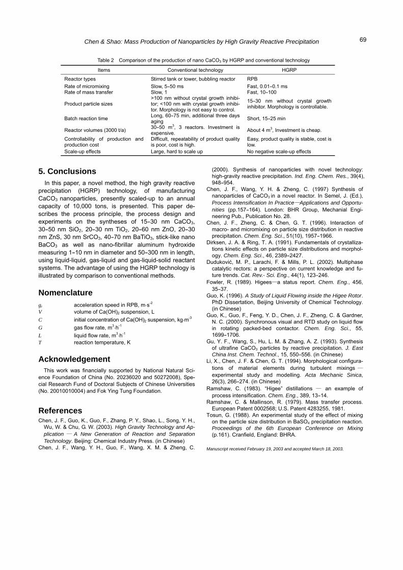
Industrial scale-up results indicated that production of nano CaCO3 by HGRP has unique advantages over con-ventional technology, as summarized in Table 2.
Chen & Shao: Mass Production of Nanoparticles by High Gravity Reactive Precipitation
69
Table 2 Comparison of the production of nano CaCO3 by HGRP and conventional technology
Items Conventional technology HGRP
Reactor types Stirred tank or tower, bubbling reactor RPB Rate of micromixing Slow, 5-50 ms Fast, 0.01-0.1 ms Rate of mass transfer Slow, 1 Fast, 10-100
Product particle sizes >100 nm without crystal growth inhibi-tor; <100 nm with crystal growth inhibi-tor. Morphology is not easy to control.
15-30 nm without crystal growth inhibitor. Morphology is controllable.
Batch reaction time Long, 60-75 min, additional three days aging Short, 15-25 min
Reactor volumes (3000 t/a) 30-50 m3, 3 reactors. Investment is expensive. About 4 m3, Investment is cheap.
Controllability of production and production cost
Difficult, repeatability of product quality is poor, cost is high.
Easy, product quality is stable, cost is low.
Scale-up effects Large, hard to scale up No negative scale-up effects
5. Conclusions In this paper, a novel method, the high gravity reactive
precipitation (HGRP) technology, of manufacturing CaCO3 nanoparticles, presently scaled-up to an annual capacity of 10,000 tons, is presented. This paper de-scribes the process principle, the process design and experiments on the syntheses of 15-30 nm CaCO3, 30-50 nm SiO2, 20-30 nm TiO2, 20-60 nm ZnO, 20-30 nm ZnS, 30 nm SrCO3, 40-70 nm BaTiO3, stick-like nano BaCO3 as well as nano-fibrillar aluminum hydroxide measuring 1-10 nm in diameter and 50-300 nm in length, using liquid-liquid, gas-liquid and gas-liquid-solid reactant systems. The advantage of using the HGRP technology is illustrated by comparison to conventional methods.
Nomenclature gr acceleration speed in RPB, m.s-2
V volume of Ca(OH)2 suspension, L C initial concentration of Ca(OH)2 suspension, kg.m-3
G gas flow rate, m3.h-1
L liquid flow rate, m3.h-1
T reaction temperature, K
Acknowledgement This work was financially supported by National Natural Sci-
ence Foundation of China (No. 20236020 and 50272008), Spe-cial Research Fund of Doctoral Subjects of Chinese Universities (No. 20010010004) and Fok Ying Tung Foundation.
References Chen, J. F., Guo, K., Guo, F., Zhang, P. Y., Shao, L., Song, Y. H.,
Wu, W. & Chu, G. W. (2003). High Gravity Technology and Ap-plication — A New Generation of Reaction and Separation Technology. Beijing: Chemical Industry Press. (in Chinese)
Chen, J. F., Wang, Y. H., Guo, F., Wang, X. M. & Zheng, C.
(2000). Synthesis of nanoparticles with novel technology: high-gravity reactive precipitation. Ind. Eng. Chem. Res., 39(4), 948-954.
Chen, J. F., Wang, Y. H. & Zheng, C. (1997) Synthesis of nanoparticles of CaCO3 in a novel reactor. In Semel, J. (Ed.), Process Intensification In Practice—Applications and Opportu-nities (pp.157-164). London: BHR Group, Mechanial Engi-neering Pub., Publication No. 28.
Chen, J. F., Zheng, C. & Chen, G. T. (1996). Interaction of macro- and micromixing on particle size distribution in reactive precipitation. Chem. Eng. Sci., 51(10), 1957-1966.
Dirksen, J. A. & Ring, T. A. (1991). Fundamentals of crystalliza-tions kinetic effects on particle size distributions and morphol-ogy. Chem. Eng. Sci., 46, 2389-2427.
Duduković, M. P., Larachi, F. & Mills, P. L. (2002). Multiphase catalytic rectors: a perspective on current knowledge and fu-ture trends. Cat. Rev.- Sci. Eng., 44(1), 123-246.
Fowler, R. (1989). Higees—a status report. Chem. Eng., 456, 35-37.
Guo, K. (1996). A Study of Liquid Flowing inside the Higee Rotor. PhD Dissertation, Beijing University of Chemical Technology. (in Chinese)
Guo, K., Guo, F., Feng, Y. D., Chen, J. F., Zheng, C. & Gardner, N. C. (2000). Synchronous visual and RTD study on liquid flow in rotating packed-bed contactor. Chem. Eng. Sci., 55, 1699-1706.
Gu, Y. F., Wang, S., Hu, L. M. & Zhang, A. Z. (1993). Synthesis of ultrafine CaCO3 particles by reactive precipitation. J. East China Inst. Chem. Technol., 15, 550-556. (in Chinese)
Li, X., Chen, J. F. & Chen, G. T. (1994). Morphological configura-tions of material elements during turbulent mixings —
experimental study and modelling. Acta Mechanic Sinica, 26(3), 266-274. (in Chinese)
Ramshaw, C. (1983). “Higee” distillations — an example of process intensification. Chem. Eng., 389, 13-14.
Ramshaw, C. & Mallinson, R. (1979). Mass transfer process. European Patent 0002568; U.S. Patent 4283255, 1981.
Tosun, G. (1988). An experimental study of the effect of mixing on the particle size distribution in BaSO4 precipitation reaction. Proceedings of the 6th European Conference on Mixing (p.161). Cranfield, England: BHRA.
Manuscript received February 19, 2003 and accepted March 18, 2003.