massachusetts bay · pdf file... transportation engineering has been ... 1.3, 2.2, thru 4.3,...
TRANSCRIPT

MASSACHUSETTS BAY TRANSPORTATION AUTHORITY GUIDELINES AND STANDARDS PART V GRAPHICS REVISED 1977

GENERAL INTRODUCTION
The Massachusetts Bay Transportation Authority has found it both necessary 'and possible to concentrate attention on the complex needs of people. Programs to improve service must now include a new emphasis on the quality of the transportation experience. In effect, transportation engineering has been joined by human engi-
. neering and environmental design.
This manual provides a framework for the continued coordination of all those elements in the system tha~ affect human comfort.
Many of the criteria involved are common to all environm'~nts, such as the control of light, noise, humidity, temperature, wind, and odors, or the need for orderliness, through clear and easy circulation and clean appearance. Other criteria that are more specific to the transportation environment are such needs as safety, traffic handling capability, spatial variety, consistently available information, and orientation.
The most important single criterion that has guided the preparafion of this manual is the need for orientation. The rider must not only be physically comfortable, he must also know in the fullest sense where he is and where he is going.
Since to the layman a public transportation system is to a large extent an invisible skeleton of the city and metropolitan region, the comprehension of that structure generates an awareness and appreciation :>f the city itself, and an appreciation of travel through it.
There are many aspects to achieving this orientation. Circulation at all pOints must be direct and open. Spaces should relate visually to their surrounding environment, either through direct openings to adjacent spaces and structures, or in the case of platforms, by graphic reflection through photographic murals.
Above all, the need for orientation places great emphasis on maps and a consistent system of identification and directional signing. Graphics then emerges as a major factor in the design of each environment, a factor that must be given high priority in the early design phases of each project.
It is hoped that all participants in all programs will familiarize themselves with the entire manual, so that the implications of each decision can be understood in a system-wide context.
The standards and guidelines presented here are not inflexible rules. They are a framework for meaningful development and variety, and offer no restriction to the capacity of each participant to evolve better solutions to old or new problems.
As new solutions are developed and approved, revised and additional pages for the manual will be issued to all participants.
(T) II ... S.CHUSI'TTI .At ftaNlltO .. TATION aUTMO'uT't'
MANUAL OF GUiDlUNES AND STANDARDS
GENERAL INTRODUCTION o
1

•
•
•
Thi s Part o f the Manual includes guidelines and standards for a wide variety of graphic elements occurring in diver e locations and media for the purposes of clear public information and Authority identification.
Each item has been developed in careful coordination with all other items, so that together they will operate as a system. It is essential if this graphic system is to work effectively, that all participants give special attention not only to consistency of use of each element, but to consistency of quality as each item is reproduced or installed.
Consis tent graphic quality contributes substantially to the Authority's public "image", and to achieve it will often require a concern for precision and for subtle visual relationships not required in other areas of the design program.
As the Graphics Program advances, many speCial conditions will arise that are not fully covered in this Manual. This will be true especially in the areas of printing and station signing. Some of these conditions will become standard items and will be described in new manual pages. Others should be developed individually, following manual guidelines as closely as possible .
Regarding station deSign, it should be noted, above all, that graphics must be given careful conSideration at the earliest phases of deSign development. Signs, maps and photomurals have an impact on orientation and station environment at an architectural scale, and as such they must be integrated from the outset with structure and space rather than be merely added as afterthoughts.
For general application of graphic elements in stations, see Part I Guidelines and Principles. For specific examples of locating major graphic elements in stations, see Part III Station Modernization Program. For fabrication details of items such as Signs, see Part IV, Components.
INTRODUCTION
"f\ E=:'. \.!.J AUT-" GRAPHICS v
IIU "~OIGUlOI""'I .""'A "1--------------------------1----1 2

PART V GRAPHICS
A. Authority Symbol and Name
1. General Description and Guidelines 2. Symbol, Diameter Larger than 4" 3. Symbol on a Square Panel, White 4. Authority Name
(Pages 2.1, 3.1, 4.1, thru 6. deleted)
B. Color Coding
1. Explanation and Guidelines - General 1.1 Explanation and Guidelines - Color Matching 2.1 T Standard Colors
(Pages 1.2, 1.3, 2.2, thru 4.3, deleted)
C. Lettering
1. Explanation and Guidelines 1.1 Explanation and Guidelines - General 2. Opaque Signs, Special Spacing Conditions 2.1 Op~que Signs, Special Spacing Conditions 2.2 Opaque Signs, Special Numeral Cases 4. Spacing Scale for Standard Cap Heights 5. Flush Left and Line Spacing Rules 6. Letter Height on Signband, Proportion Rule 6.1 Sign Band Heights - Stacked Sign 7. Arrow/Circle 7.1 Arrow/Circle - Directional Conventions 8. Use of Arrow/Circle - Opaque Sign Bands 8.2 Use of Arrow/Circle - Continuous Opaque Sign Bands 8.3 Use of Arrow/Circle - Line/Direction Signs 8.4 Use of Arrow-Circle - Directional Signs, Margin Rule 8.5 Use of Arrow/Circle - Stacked Sign Bands 8.6 Arrow/Circle - Incorrect Usage
(Pages 3.0 to 3.2, 8.1, 9.0, 9.1, 10., 10.1, 10.2 deleted)
T ... TRANSPORTATION GRAPHICS v <r) MASSACHUSlTTS
AUTHORITV t-------------------------.. ---.. MANUAL OF GUIDELINES AND ITANDARDS
REVISED 1977 CONTENTS 3
•
•
•
D. Maps
1. General Descriptions (Pages 2 thru 4.1 deleted)
E. Vehicle Painting (For META Use Only)
F. Station Entering Signs
1. General Description 1.1 Diagrammatic illustration - Sign types 2. T Symbol - Backlit Street Sign 2.1 T Symbol - Backlit Street Sign, Applications 3. Station Name and Hours - Backlit Street Sign 3.1 Station Name and Hours - Backlit Street Sign 4. Maps/Lists of Stations - Non-directional Combinations 4.1 Maps/Lists of Stations - Directional Combinations 4.2 Maps/Lists of Stations - Platform Groups of Four _ 4.3 Maps/Lists of Stations - Platform Groups of Three 4.4 Maps/Lists of Stations - Platform Distribution 5.0 Lists of Stations - Inbound 5.1 Lists of Stations - Outbound 5.2 Lists of Stations - All Trains 6. Line/Direction Signs - Basic Units 6.1 Line/Direction Signs - Variations and Details 6.2 Line/Direction Signs - At Decision Points 6.3 Line/Direction Signs - As Reinforcement 7. Incorrect Uses and Combinations 7.1 Special Sign and Map Units for Green Line Surface
Platforms (Pages 3.2, 3.3, 4.0a, 4.la, 5.3 deleted)
G. Station Exiting Signs
1. General Description 1.1 Diagrammatic Illustration - Sign Types 2. Name Bands/Station Name - Use 2.1 Name Bands/Station Name - Spacing 2.2 Name Bands/Station Name - Sample 2.3 Name Bands - Linear Continuity 2.5 Name Bands - Porcelain Enamel Joints 3. Information Band - Basic Use 3.1 Information Band - Spacing of Directional Signs 3.2 Information Band - Necessary Interruptions 3.3 Information Band - Line Transfer Use 4. Directional Signs - Details 4.1 Directional Signs - Backl it 4.2 Directional Signs - Stacked 4.3 Directional Signs - Perpendicular to Train, Backli t
and Opaque Perpendicular/Backlit . 5.1 Incorrect Uses and Combinations
CT) ~Ae:.aCJfU •• n . ... '"u • .,...,.. ... " Otf a,,"fitMfn
"IVIIED 1'"
(Pages 2.4, 5.0 deleted)
GRAPHICS
CONTENTS
v 4

H. Station Art and Platform Photomurals
1. General Description 2. Typical Example 3. Linear Continuity - Relationship to Train 3.1 Linear Continuity - Wall Construction
I. Miscellaneous Signs
1. General Description 2. Emergency Signs - "Emergency Exit" Backlit Sign 2.2 Emergency Signs - "Fire Hose" 3. Warning Signs - "Danger No Passing" 3.1 Warning Signs - "Keep Back of Yellow Line" 3.2 Warning Signs - Escalator 3.3 Warning Signs - "Danger Third Rail" 4.2 Advisory Signs - Toilet Rooms 4.4 Advisory Signs - Clock Face 5. Authority Facilities - "T Personnel Only" 5.1 Authority Facilities - Door Numbering
(Pages 2.1,3.4,4.0, 4.1, 4.3, 4.5, 6.0 thru 6.3 deleted)
J. Roller Destination Signs (Not included in this edition)
K. Bus Stop Signs (Not included in this edition)
L. Revenue Advertising
M.
N.
1. General Description and Guidelines 1.1 General Description and Guidelines
(Pages 2.1 thru 4.1 deleted) 5. Typ. Advertising Support Frame 5.1 Alternative Advertising Supports 5.2 2 Sheet Advertising Panel 5.3 6 Sheet Advertising Panel
Printing
(Not included in this edition)
Drawings
(Not included in this edition)
<T> MASSACHUII!:TTI
T I.' TIIIANS'OR'A'IOH AUTHOR lTV
MANUAL OF GUIOELINES AND ITANOAIlDI
REVISED 1971
GRAPHICS
CONTENTS
v 5

•
•
PART I
PART II
PART III
PART IV
PART V
PART VI
PART VII
PART VIII
PART IX
PART X
PART XI
®E-;~
MANUAL OF GUIDELINES AND STANDARDS
. GUIDELINES AND PRINCIPLES
STATION RECONNAISSANCE (Discontinued)
STATION MODERNIZATION PROGRAM (Discontinued)
COMPONENTS
GRAPHICS
LIGHTING
MATERIALS
ACOUSTICS
SERVICE FACILITIES
SITE PLANNING AND NEW STATIONS
VENTILATION
GRAPHICS _01_~_._n __ 1---------------------+--....
1
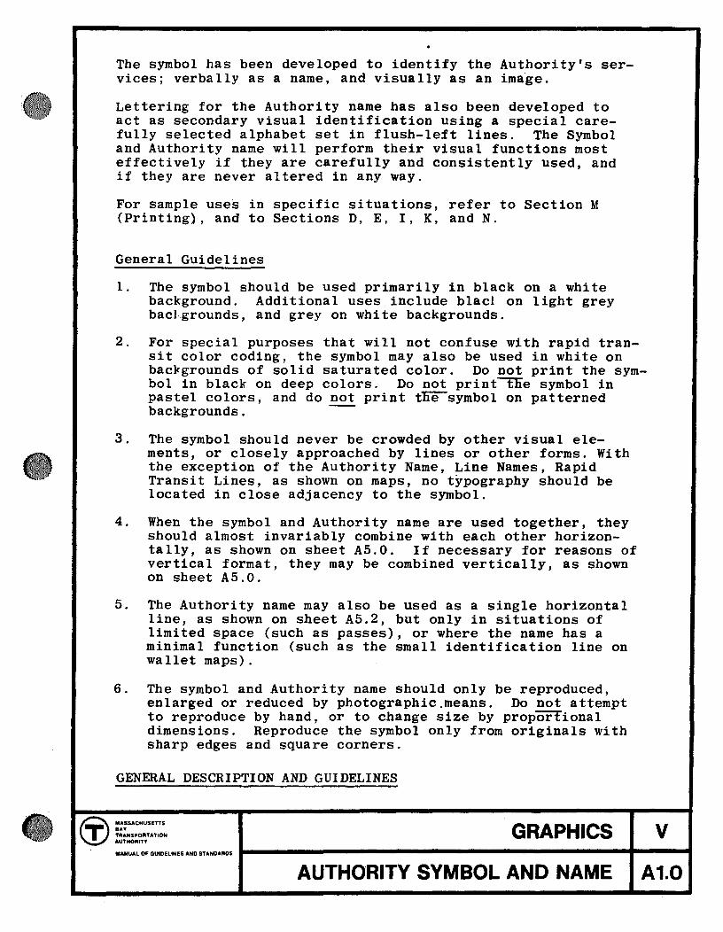
The symbol has been developed to identify the Authority's services; verbally as a name, and visually as an image.
Lettering for the Authority name has also been developed to act as secondary visual identification using a special carefully selected alphabet set in flush-left lines. The Symbol and Authority name will perform their visual functions most effectively if they are carefully and consistently used, and if they are never altered in any way.
For sample use~ in specific situations, refer to Section M (Printing), and to Sections D, E, I, K, and N.
General Guidelines
1. The symbol should be used primarily in black on a white background. Additional uses include blacl on light grey baclgrounds, and grey on white backgrounds.
2. For special purposes that will not confuse with rapid transit color coding, the symbol may also be used in white on backgrounds of solid saturated color. Do not print the symbol in black on deep colors. Do not print"tlie symbol in pastel colors, and do not print tne-symbol on patterned backgrounds. -
3. The symbol should never be crowded by other visual elements, or closely approached by lines or other forms. With the exception of the Authority Name, Line Names, Rapid Transit Lines, as shown on maps, no typography should be located in close adjacency to the symbol.
4. When the symbol and Authority name are used together, they should almost invariably combine with each other horizontally, as shown on sheet AS.O. If necessary for reasons of vertical format, they may be combined vertically, as shown on sheet AS.O.
5. The Authority name may also be used as a single horizontal line, as shown on sheet AS.2, but only in situations of limited space (such as passes), or where the name has a minimal function (such as the small identification line on wallet maps).
6. The symbol and Authority name should only be reproduced, enlarged or reduced by photographic.means. Do not attempt to reproduce by hand, or to change size by proportional dimensions. Reproduce the symbol only from originals with sharp edges and square corners.
GENERAL DESCRIPTION AND GUIDELINES
T ... TRANSPORTATION AUTHORITY
GRAPHICS v (y) MASSACHUSETTS
MANUALOFGUIDELINESANOSTANOAAOS 1-------------------------... ----1 AUTHO"RITY SYMBOL AND NAME A1.0
•
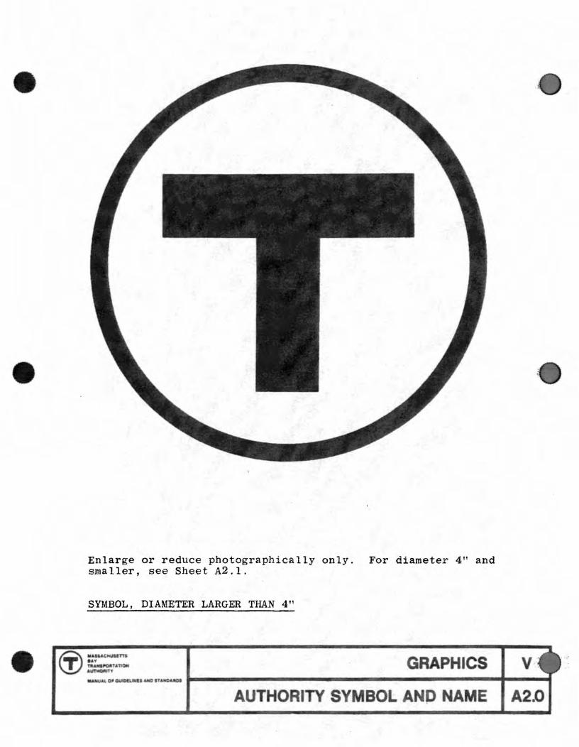
Enlarge or reduce photographically only. For diameter 41f and smaller, see Sheet A2.1.
SYMBOL, DIAMETER LARGER THAN 4"
t:r =::..~ \!.I a~ GRAPHICS v _MUAl.o._ ...... n ..... UIOI .... ------------------..... ~-.....
AUTHORITY SYMBOL A P NAME A2.0

The symbol must be in a 7:9 ratio with the background. See Sheet Al.O for notes on usage. See Section K (Bus Stop Signs) for a typical application.
SYMBOL ON A SQUARE PANEL, WHITE
® MA$SAC><USETTS
GRAPHICS lAY T TRANSPORTATION AUTHo'nTY
MANUAl.. OF GUICELIN(S "NO' STANDAROS
AUTHORITY SYMBOL AND NAME .
V
A 3.0

•
•
•
letterTheight I
~ l.h. -1"-t-let ter I height
~ 1. h. letter height
~ 1. h. letter ' ; height I
-,r-
MASSACHUSETTS BAY TRANSPORTATION AUTHORITY
Use the Authority name exactly as it 1s shown on these pages. Change the size of the name by photographic process only. Artwork should be obtained from the Authority. Do not use these pages as artwork. They are examples for size only.
The Authority name must always appear in the Standard Alphabet -Helvetica Medium, and flush left as shown here. Line spacing remains the same at all sizes except 8 pt., 7 pt., and 6 pt. These are set solid because of their frequent use in restricted positions.
Do not use other alphabets, no matter how similar they may seem. Do not alter the flush left margin. Do not alter the spacing between lines. Note that special relationships exist between letters within the words.
For fluSh-left margin rule see C5.0.
AUTHORITY NAME
GRAPHICS v AUTHORITY SYMBOL AND NAME A 4.0

The primary fuction of the Authority's color coding is to give clear identity and structure to tbe routes of the Rapid Transit Lines. When carried out consistently on a system-wide basis, on station signs and many otber elements, color coding will help significantly in making the system legible.
The colors Red, Blue, Green, and Orange bave been reserved for tbe Rapid Transit Lines, and Purple for Commuter Rail Lines, and Yellow for buses. The co Brown bas also been reserved for a future additional line. To prevent confusion, these colors must not be used on signs for any purposes otber tban identification of tbe Rapid Transit Lines, except as noted in tbis Manual.
Tbese colors, or sbades of tbese colors, and otber colors used for station finisbes must not compete or conflict witb tbe color coding system. Large areas a line color may be used to emphasize tbe identification of a line, particularly in stations wbere two rapid tranSit lines connect.
Tbe vebicle color scheme is an extenSion of the line color coding systems. Typcially, the vehicles have ligbt gray roof and skirts, a wbi te band in the window area, and the line color band between floor and belt rail.
The color Yellow is also used for signal and warning purposes. Yellow is used for platform safety striping, service vebicles, and any other purposes tbat require maximum visibility for safety. It must not, however, be used as a background color for signs.
EXPLANATION AND GUIDELINES - GENERAL
GRAPHICS v
REVISED 1$17 COLOR CODING 81.0

•
•
Th Authori y ' andard colors ar 0 nece 1 y applied 0 a wid var1 y of mat rials and surfac ,u 1n many diff r e n ink and pain s . Th e inc Iud porcelain enam I on t I, spray-paint d aluminum paper of all type. polyvinyl fluorid films, back-illumina d acry l ic p i a ie plywood, and man y other .
In each case it i extrem Iy important to achieve the bes posible color match to th ample i n thi manua l , and 0 pro 0-type pr viously developed and approv d. For exampl , on Red Line and Oran Line si n I do not u e any r e d and orange t ha seem clo e h n exac rna che ar po ibl inee confusion be we n the two color may re u l .
ote that th colors ar called 'RTL R d" , .. BTA Grey Ill " , etc . a nd that each is a pecific hade and hue. The specific colors mu t be us d consistently throu hout h y tern on all sign map, prin ed mat rial v hicle pain tng , ta iOD pain -ing etc .
EXPLA ATION AND GUIDELI ES - COLOR
(T) "~ ••• T "' .. ~. . - GRAPHICS v
COLOR CODING 81.1

® Sta ndard Colors (Spray) (Brush)
IMRON DULUX
Color Use Chart No. Code No.* Code No.* - -Red Red Line Red 93-58209H 93-58209H Blue Blue Line 66 11257U 93-17251 Orange Orange Line 14 60659U 93 ... 60659H Green Green Line 94 5316U 93-5316 Yellow Bus, Trackless .... 93-6808
Trolley Chrome Yellow
Dark Grey System Wide - 93-55322 Light Grey t! " 55 55131U 93-55137 White " !! 48 l517U 93-21667 Beige " H 44 4480U 93-96923 Purple Commuter Rail - 1976 UM (Hyde) Aqua Handicapped 78 12218U 93-72218 Black System Wide 59 99U 93-005
* On Dupont Dulux and Imron Transportation Finish Master Color Guide
The above colors have been designated as standard colors for the Authority. This does not constitute an endorsement of a particular brand, but is used for convenience due to the wide availability of color samples and paints. These particular colors are ones which can be most successfully matched in the porcelain enamel process. The Authority can provide porcelain enamel color samples to contractors as required.
META Standapd Colors for Printed Material (patpr Stock): antone Nos.)
Color Use Uncoated Stock Coated Stock
Red Blue Orange Green Yellow
Purple Aqua
Red Line Blue Line Orange Line Green Line Bus, Trackless Trolley Commuter Rail Handicapped
485* 485 293 285 144* 152 348* 348* 123 123
241 249* 334 334
* As these are not an exact match, they are the closest pantone has to offer.
GRAPHICS
COLOR CODING
v
82.1

•
•
•
Th Authori y' s andard alphabet, called H Ivetica t dium, ha b en cho en for maximum legibility a all izes and availabili y in many m dia. Since the consistant use of one alphab t on all signs, map and prin ed ma ter contribu es ubstantlally 0
h Au hority's vi ual unity, no other alphab t hould be ubi u ed however imiiar it maY-appear to be .
pacing rule from Ie role er and word to ord ar ba d on th optical wei ht of each letter hape. Th se hould b follow d xac ly. 0 e tha spacin rule for backlit s1 n ar more op .0, to compen at for th optical xpan ion, or flare, of backlit Ie ters and word.
For applica ion requir1n a Ii h er typ face uch a tex (e Section I , Printing) a machine- et varia ion, called R 1-vetica (Light) is available. An extra bold variation called H Ivetica Bold i u ed exclu ively for terminal name on map ( ee Se ction D) . For div r application of h alphabe.
other Section of hi anual.
General Guidelines
Th spacing rUl s iven on Sh t C2 . 0-C2.2 mus b follow d on all i ns r Quiring lett ring of l' cap hei ht or lar er. Do no enlarg to he e sizes photographically from smaller typ -set copy . a spacin will b d ifferent and Ie 1 ible.
2. For applications requ1rin let ering maIler than 1" , copy may b t 1n type and ordered from most typ composi ors. either as prin ed reproduc ion proofs from lead ype or as photo raphic proofs from phototyp ne a iv
3. Do no a tempt to reproduce Ie tering by hand a or to cut silk cr en s encil by hand. For larg such a i nand vehicl marking , use die cut pre
n itlve film 1 tter applied directly, or prepare silk screen encils photo raphically from fini h dart ork
ha ha been mad up u ing compositor's proofs, die cu film Ie ers, or ransf r wax letter .
con ioued
D GUIDELI S
GRAPHICS v LETTERING eto

4. Note that Helvetica Medium is available in wax transfer letters (by Letraset or equal) in a large variety of sizes from most artist supply stores. These wax letters are not durable, but can be used for temporary signs, for signs not subject to abrasion (such as office doors), for the preparation of artwork, and for lettering on architectural and engineering drawings. Do not attempt to compose lines of copy in very small sizes using these transfer letters, where compositor's proofs can be used with more precise results.
5. When a change of size is required from proofs or artwork, this should be done exclusively using photographiC techniques (film negatives and glossy prints), or photostats (glossy negatives and glossy prints) so as to maintain dimensional accuracy, sharpness, and consistant lettering weight.
6. Note that the design of almost all items for the Authority using stacked lines of typography sets the lines either flush left or flush right. Do not center lines under each other, except as shown in Section M, and special cases noted as such in Sections F and G.
EXPLANATION AND GUIDELINES - GENERAL
GRAPHICS v MANUAL Of GtJIO-U .. tHf$."C$T4WOA.!I!'O$ 1-------------------------... ----1
LETTERING C1.1
•
• • t c C • t • • ••• • • • • • • • •
ABCDEFGHIJKLM c, .. c: , c ( C .. ., • , .... • .. c
OPQ TUVWXYZ , _c e: ~ .. cc tC c. .. 6 ( c. tt C 4 ....... co C .. . . c
J
1234567890&'.;: !()
fA ... " I .. lt l' t C • curv 't'~r
.
S - .tr.l~ • , II r . ) .. .. . c ,. I , J
XIT TO BU
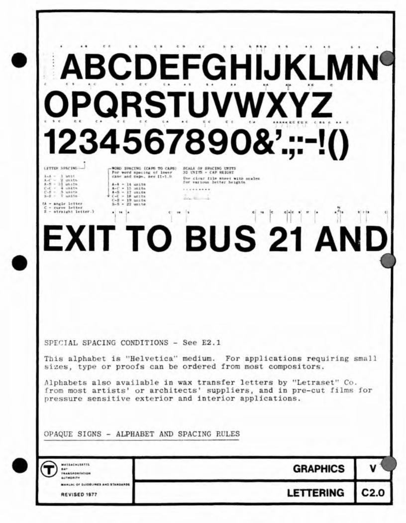
spr~I L S ACI G CONDITIO S - Se E2.1
C ••
T 1s Iph s1' s, YP
t i " H 1 tica" medium. For appl cations r quir ' n sm 11 or roofs c n be ord r d from most compositor.
. 1 ba ts from mos pr ur
o
(j) .. " Coli"'" ... , .. .... " •• u,. 4 Ut tin.
Iso a ailabl in wax tran fer I e ers b "Letras "C rt'sts' r archi ects' u plier I and in pr -cut I'lm. for
sensi iv x rior and interior applications.
GRAPHICS v
REVISED ,.n LETTERING C2.0

!: j ': l
-----TA FA J TT FT f; 1:~ ti l; I
2, :!i ,
~APA TVT FV , ;
;;; : ] :
AWA LWTWTFW ; i 1 ~ . 1
AVA LV TVT FV ~ : ) j
P. F. T. V. W. V. : ' I
SPECIAL SPACING CONDITIONS - OPAQUE SIGNS
i 1.Y<.
Us e these spacing un i ts wh e rever these combinations occur.
CT) fittA: ~S "' f "'ti·t.f"!1' ~ 6«
f ~ ",h; § ~O" "' '' ! ~O '''
.... i;fIoH)JHf'r
GRAPHICS v
REVISED 1977 LETTERING C2.1

•
1A. • 1 • 1111 116 I
3 A.M. 3 • 1101 ! 131 115 I
7A.M. .M. 116 I I 22 I 15 1
Use these special spacing relationships when combining numerals with letters A.M. and P.M. to make opaque signs regarding times, Note that numeral-to-Ietter spacing is one-half the normal word spacing modified and adjusted to the Special Spacing Conditions.
OPAQUE SIGNS, SPECIAL NUMERAL CASES
GRAPHICS " . t u ,o ..
LETIERING
v
C2.2
1in
2 I HI 14 HI If 21 10
n 4 8 12 16 20 24 28 32 t i 10 14 " 22 1$ • • • • It 18 10 Z. 28 »
6 . In
2 I 10 14 18 22 26 30 o 4 8 12 16 20 24 28 32
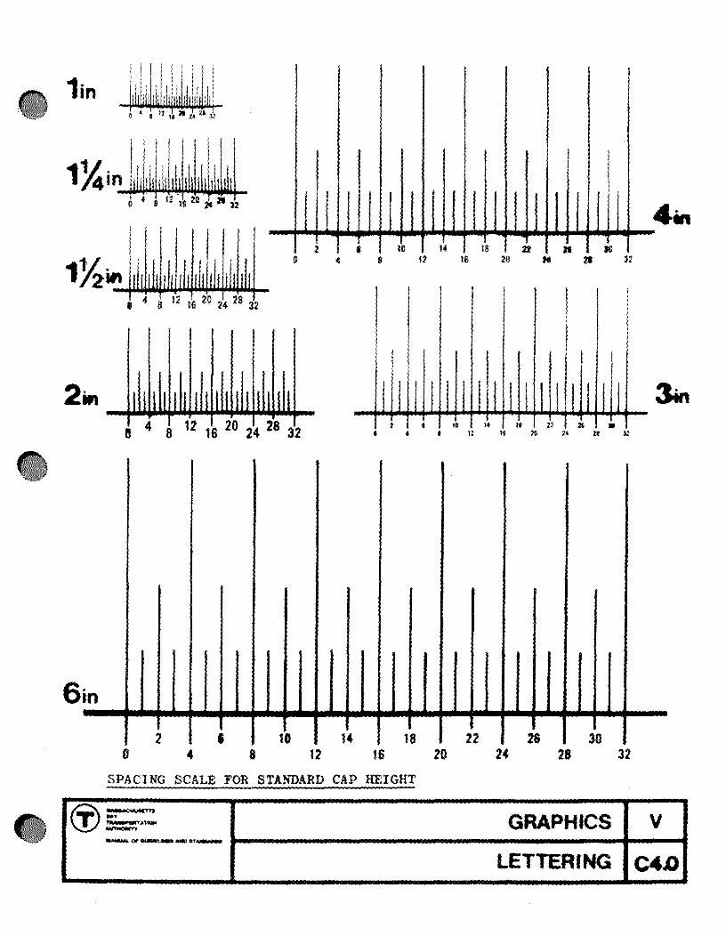
SPACING SCALE FOR STANDARD CAP HEIGHT
~:: ... ~ GRAPHICS V - .. ~ ~ _ ... _--_ .. -LETTERING C4D

•
•
•
X (1 ~. I.: t hat Angle letters extend over the margin 3 units
Flush left letters A,V,W,X,Y,T numbers 1,4,7.
Flush right letters A,K,T,V,W,X,Y number 7.
1/2 heigbt of straight letter
1/2 height of straight
Note that curved letters extend over margin by 2 units
Flush left letters C,G,O,Q,J
Flush right letters C,D,O,Q numbers 3,6,8,9,0. J
These rules also apply to lists that are flush right. Line spacing only applies to lists with lettering all same size.
FLUSH LEFT RULE, LINE SPACING RULE
GRAPHICS v LETTERING C 5.0

For all signing (except for special cases shown in following sections) lettering must relate to signband in a 2:3 r~tio whether black letters on a ·· whi te background, white letters on a black background, or white letters on a colored background. Examples are 4" letters on a 6" signband and 6f! letters on a 9" signband. .
NOTE: Cap height is always measured on a straight-edged letter.
LETTER HEIGHT ON SIGNBAND, PROPORTION RULE
~ .... SSACHUSETT.
GRAPHICS V IA. T TRANSPORTATION AUTHQ'UTY
..... NUAL. OF GUIO!I..!HES ANO ST.HOARDS
LETTERING e6.0
•
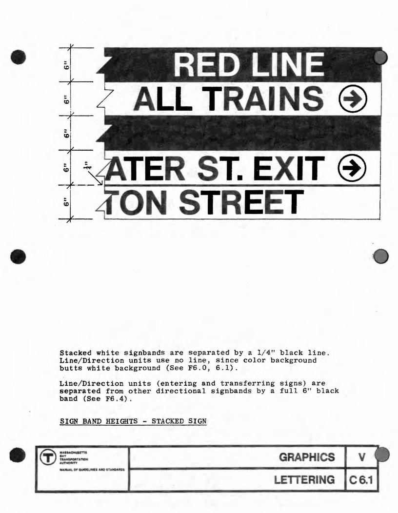
Stacked whitesignbands are separated by a 1/4" black line. Line/Direction units use no line, since color background butts white background (See FB.O, 6.1).
Line/Direction units (entering and transferring signs) are separated from other directional signbands by a ful l 6" black band (See F6.4).
SIGN BAND HEIGHTS - STACKED SIGN
Ci}- GRAPHICS In :=rAYIO<f _Of'_&lDITAJIOUDI
ETTERING
V
CS.1

up
1"
45° up left ~
450 up right 71
left~ -1 right
450 down left ~ ~ 450 down right
~ down
This arrow - circle unit is to be used on all directional signs, and only in the eight attitudes shown. For correct usage, see Sheet C7.1. Do not use the arrow without the circle, except as specified in this manual for special application.
ARROW/CIRCLE
® 'U5SACHU8£TTS
GRAPHICS V BAY T TRANSPORTATION AUTHORITV
..... NUAl 0' GUIDeUNES AJ.K) $1ANOolRDS
LETTERING C7.0

.,...-_--------------------------...
Go left
1(1) Go up
I~ Go down or straight You have arrived
I® Up left, or half-left
i@ Down left only
Go right
Go up
Go dQwn or straight You have arrived
@I Up right,
or half-right
®I Down right only
These are the proper attitude positions for the Arrow/Circle decal. Use the Arrow/Circle eit11er lett or right. Do not use on both sides of a sign unless one end or the other is obscured by a column, wall, et~. from some viewing positions.
See CS.O and CS.l for relationships to the edge of the sign. See Sections F and G for use.
ARROW/CIRCLE - DIRECTIONAL CONVENTIONS
(j) .... I.C,.Uln1'1 1&, ' -••• sIllOA" o •
• "'MO.'"
REVilED 1'77
GRAPHICS
LETTERING C7.1
6"
6"
10"
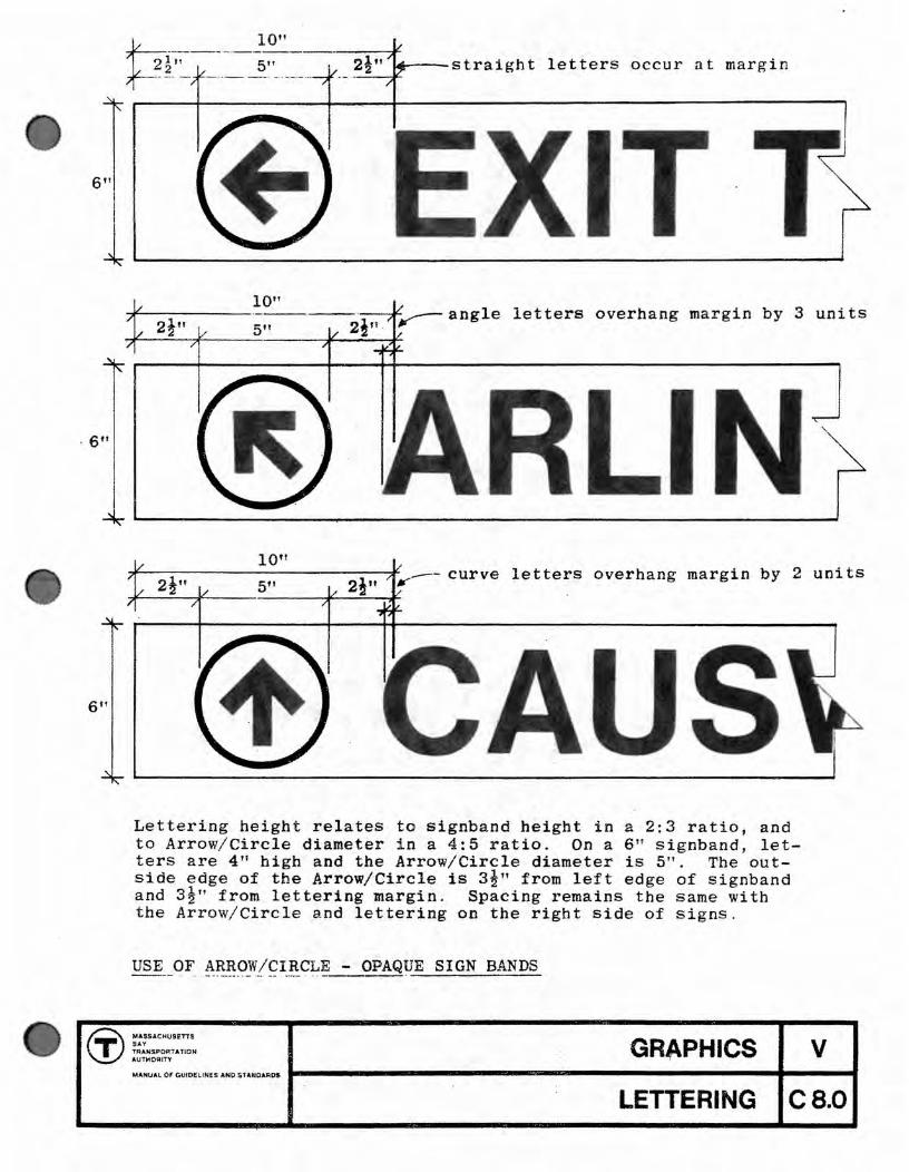
.... --straight letters occur a t margin -....:;--:~
10" angle letters overhang margin by 3 units
curve letters overhang margin by 2 units
Lettering height relates to signband height in a 2:3 ratio, and to Arrow/ Circle diameter in a 4:5 ratio. On a 6" signband, letters are 4" high and the Arrow/Circle diameter is 5". The outside edge of' the Arrow/Circle is 3!" from left edge of signband and 3!" from lettering margin. Spacing remains the same with the Arrow/Circle and lettering on the right side of signs.
~ MASSACHUSETTS
GRAPHICS V SAY T TRANSPORTATION AUTHORITY
MANUAL 01 GUIDELINES AHO STAIriIOAROI
LETTERING eB.O

Single floating directional sign
7!" minimum
Two adjacent directional signs
USE OF ARROW/CIRCLE - CONTINUOUS OPAQUE SIGN BAND
~ :::SACllUUTn
-.~ AImIOOItT't GRAPHICS v
MAW ""GUO ....... at_AlI31----------------..... ----.... --LETTERING C 8.2

5"
equ
5" 4"
equal ->t.---
2 units, curve letter
On signbands that provide information together, as a pair, the arrow must only appear once, on the white band. For typical combinations of this kind, see Sections F and G.
USE OF ARROW/CIRCLE - LINE/DIRECTION .SIGNS
(J:) MASSACHUSETTS
GRAPHICS BOY T TRANSPORTATION AUTHOR!T't
M4NUAL OF GUIDELINES " NO 51 ANDA.RDS
LETTERING
V
CS.3

10"
\~----------------------------.
3 units, angle letter
Maintain the left or right margin of a signing band in the adjacent bands. Do not allow the lettering of one line to run across the margin of one directly above or below it.
Note that lettering two lines away may violate the margin to gain copy-fitting space. See Sections F and G.
USE OF ARROW/CIRCLE - DIRECTIONAL SIGNS. MARGIN RULE
~MU~~' GRAPHICS ••• T , . .&.1If'IPOtIT A naN AuntO""",,
...... ~L 01' CWlDZUMD 'M) nQD_ADIl
LETTERING
V
C8.4
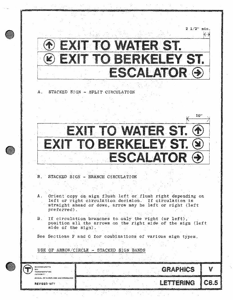
A. STACKED SIGN - SPLIT CIRCULATION
10"
B. STACKED SIGN - BRANCH CIRCULATION
A. Orient copy on sign flush left or flush right depending on left or right circulation decision. If circulation is straight ahead or down, arrow may be left or right (left preferred) .
B. If circula on branches to only the right (or left), position all the arrows on the right side of the sign (left side the sign).
See Sections F and G for combina ons of various sign types.
USE OF ARROW/CIRCLE - STACKED SIGN BANDS
MASSACHuseTTS OAY TFli$.U$PORTAT10N GRAPHICS
~
v LETTERING CB .. S

WATER ST. EXIT (f) @ ARLI GTON ST.
ESCALATOR @ a. Top band should be flush left, or middle band should be
moved to top. Sign bands should not, without necessity, alternate left-right (See sheet C6.4).
Top band also violates directional signs margin rule (See sheet CS.4).
WATER ST. EXIT @ I b. Arrow and copy should be shifted flush left. Arrow should
never point toward copy.
~ESCALATOR c. Arrow and copy should be shifted flush left. Information
should never be centered, except on continuous sign bands of indefinite length.
ARROW/CIRCLE - INCORRECT USAGE
cr> ::Uc.oUUTTS ,.... OIl'tA lOIII .a"""OItfTT
GRAPHICS v MA .~OO'c Dt:~ ..... ,,_ ". t-----------------------...ot~--_I
LETTERI G CS.6

The Authority's maps are designed to vide information in varying roes of detail according to specific needs,
Transit inform3tion is often required by passe in a hurry, as a quick reference. In to this, the Strip Maps ("LinE'" ) wi thin the rapid transit cars allow the sequence of stations and transfer points to be read at a glance. Similarly. the RTL Map gives schematic structure and clarity to the entire rapid transit system and is also designed to be read quickly. Unessential information is eliminated.
In each case, the are designed for maximum clarity and for consistency with their overall map family in type, color and symbols. Additional or revised maps that may be required from time to time must maintain this consistency within their map family.
In addition to the famil of transit maps, a neighborhood map is to be provided in each station as a public service. Transit information such as connecting bus routes and the locations of bus stops are included where they occur, but the primary purpose the maps is to provide detailed information about streets, address numbers and points of interest in the neighborhood surrounding the stations. A "You Are Here" decal, applied individually to each map. further helps to orient the passenger.
It should be noted that the coding system of the maps uses three major elements: Color for the Rapid Transit Lines, Letters for branches of the Rapid Transit Lines, and Numbers for the Bus Routes. These coordinate with roller destinati"on Signs and with bus stop signs as shown in Sections J and K.
GENEHAL
MA~J ~~At.HU;~f T r:-, 5';'1-
1'~A~"'1f<r><1~!, A H)~
PTION
GRAPHICS v
MAPS 01.0

•
•
Compr h n · on of the i nin y t m and of it application at tation , b com s clear if one race all pos ibl pas en r
rout and analyze each d cision poin for he en ial in-forma ion requir d at that point.
Thi s ction 0 the anual outlines hue of basic ignin typ s encount r d by th enterin passenger (som of which are also encoun r d by th tran rrin pa s n r).
The ent ring equenc b to he tation a10n ci the corr train for hi
approach rout hi boarding
There ar ba 1 criteria that should b reme b red in i ning each d cision point: deSigns ion of all cboic maximum visi-bili y and maximum 1mplicity. Un ntial information hould not be included, particularly 1n narrow irculation ar a where a lingering pa nger may block traffic flow . R ferenc items to b s udied in d tail uch a map , hould b locat d only at far colI cion lobbie pIa orm and wid pa a eways where raffic will not becom blocked .
In ta ions where xi ting wall pace at fare colI ction area is inadequa e for the requirement of prop r signin . i is extrem ly important to increa that wall pac. inimum urfac should b 16', both in id and outside fare collection, and thi should be accomplished by revi ion of exi tin wall or construction of new fr e standin panels .
ot that revenue adv r i in ,a d scrib d in effect th last graphic item in the enterin
ection L. is in quence, en by
th waiting pass n er befor h board hi rain.
GE ERAL DESCRIPTIO
r.r ~:-"lH ' ~ aulf11O'Uf'T GRAPHICS
01 GUGI L II
STATION ENTERING SIGNS
v F1.0
8) :D t: ..... '"
~ c .... z ......
< " in 1:
'" ~ c .. c: ... ;; co ~ '" ... ~ .. ..
" ., ~ ,. z
" .. " ~
en -t )I--t -0 z m z -t m ::D - C) z C) ::D
')1-en ." - ::x: C) -z n en tn
." < .... ~
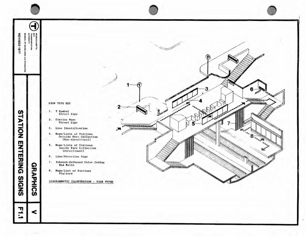
SIGN TYPE KEY
1. T Symbol Street Sign
2. Station Name Street Sign
3. Line Identific ation
4. Maps / Lists of Stations Outside Fare Collection
(Non-directional)
5. Maps / Lists of S tations Inside Fare Co llectlon
(directional)
6. Line/Direction Sign
7. Inbound-Outbound Color Coding End IIa11s
8. Maps / List of Stations Platform
./,) /
J /
......
DIAGRAMMATIC ILLUSTRATION - SIGN TYPg;;
" , /~;-. , .~~--"
<T-

The basic T Symbol Backlit Street Sign is used to mark the location of RTL stations " See Part IV, Components, for dimensions, outline specifications a nd installation.
T SYMBOL - BACKLIT STREET SIGN
®~~ GRAPHICS .. , T ", . ..sOOll'TA~ • ...-m ~ Of' G\ICOtI.JHU, AIiIID .'U1DMa&
STATION ENTERING SIGNS
V
F2.0

1 . Pole Mount 2. Side Mount
3. Suspended Mount 4. Surface Mount
Use the Illuminated Symbol as a beacon to identify RTL stations -at street or surface level (See I-H.6; IV-AS.O - AS.4).
1. Pole Mount - standard application.
2. Side Mo~nt = attach to nearby building or structure, where sidewalk is too narrow or crowded for pole.
3. Suspended Mount - hang symbol from major structure, where necessary to relate to visual environment.
4. Surface Mount - only where space prohibits either (1) or (2) ,
T SYMBOL - BACKLIT STREET SIGN - APPLICATIONS
® MA.SSACHUSETTS
T B'Y TitAN! POATATIQH AUTHORITY
GRAPHICS v MANUAl., OF GU!DEUNE$AftiDSTANOAADS ...... ----------------------..... 1---...
STATION ENTERING SIGNS F2.1

ARLINGTON THIS ENTRANCE WILL BE OPEN
5:15 A.M.·1 A.M. DAILY
The basic Station Name and Hours sign is used over the entrance to RTL stations.
The Station Name appears in white on a background of the RTL color of line of the station. Name and Hours signs generally fill the full width of the opening to the RTL station.
The hours of opening appear in black on white in varying sizes . See following pages for copy-fitting samples and examples of entrance information.
Note: all lettering is centered within the width of the sign. This is the only case of RTL station signing in which lettering is neither flush-left or flush-right, except for the centering of copy within structural bays of the station platform.
STATION NAME AND HOURS - BACKLIT STREET SIGN
~~~~ T ::: ... oatAflON ~.fT\'
GRAPHICS 1UrJIIU&.L QP 4UGI:UNU uro aTAJiIIIOAIIIDI
STATION ENTERING SIGNS
V
F3.0

(3) It ...... a lit : s=~: < "I: = - ~. 2 n
:: t =! i
... !:
~ £ i ~ ~ PULL WIllTH 01' sorAnCASI! ·OR DOOM L ., Ii: • • 1 .... ! ., "
~ ~ -0 Z III
~ m :D -Z t;) (I) -t;) Z (I)
.. • • · ~ .. II: • • •
--n
t;) ::D ,. ." % -n rn
WI< • ..
THIS ENTRANCE WILL BE OPEN 5:15 A.M.-1 ~"' •. DAILY
THIS IS AN EXJT ONLY. ENTRANCES OPEN 5:15 A.M. -1 ~M.. DAILY
;,1
~I
THIS ENTRANCE WILL BE OPEN 5:15 A.M. -1 A.M. DAILY
TYPICAL
STAT10ll "AMI AlI0 HOUIB - BACKLIT STRDT BIG"
;..
• ...
• ...
~I
~I
:.1
:..1
:'1
till rT8 U'l1'8 Ita 011 BLUIl P(IILD
IUCE L!T1'I!1lS a. IMIT8 PlSLD
WItlft UTI'll ItS 011 UD/GUeN nuos
auca LltftaB ill 1M.Ift .PIII'" 1101'S: J" CAP DUIIT ,.. STlTJOIf "AD IS WID O. TII18 SIC. UCAUSI or a.I ","I"G Ll1IlTAn BTAtmllIO .... urrrIU
OULD 1m TOO CIIOWDItD.
WIUTII U TI'II1tS ON 01lA1IGB PI8LO
.,Uft LI'PnIl.S a. CIUIIUI pIBt.D
lLAC1[ LATTIU a. WlUn PULD
:II III < ;
"' o ~ .., ... ..
(/)
E -0 z m z -4 m :u -z G')
en -C) z en -"
8) : ; =!: ~ &: r ,.. ... ., ~ :: ~ , ; !; ~ e ~ • 5 · • a
= .. • a • .. Ii:
C') :Jl ,. ." ::J: -n en
~I < . 0
COIIB(IUTIOH NO.1
COMBJN~TIO~ NO . 2 16'-0"
:='=-::::.. §
LS-l
COIIBUIATIOlf "0. 3
24'-0"
t 4'-0" r
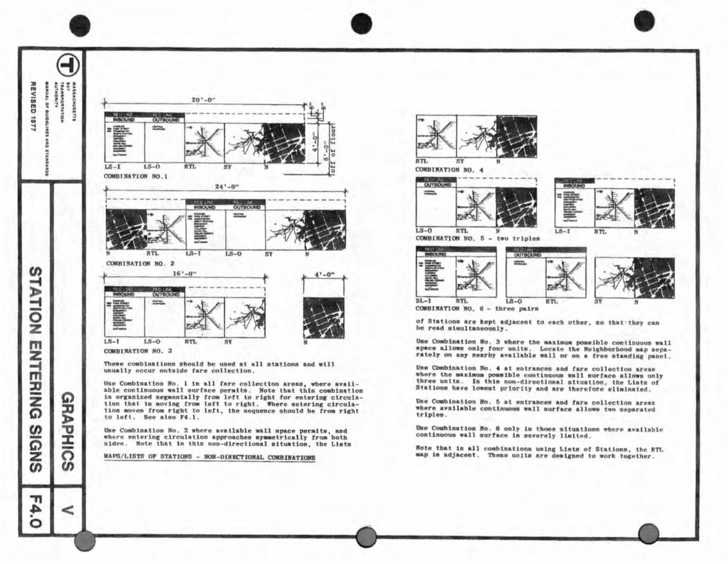
Theee r.a.blnatlons abould be used at all .tatLon. aDd will usuall, occur outside tare collection.
Use Cu.blnalloo No . 1 10 all taro collect ion are .. , wber. available continuous wall .urface peralta. Hote tbat tbLs ca-bloatlon hi orraDic.d .epenhU, (1'0lIl lett to rl,bt tor enlertDIr circulalion tllal ts Bovinl fr_ leU to rlCht. Where enterln, circulation &Oves froa right to left, the enquence should b. Ira- rl_bt to l~'l. Se. alao F4 . l .
Us. Co.blnatloo No. 2 .h~r. available wall a pac. p.ralta, and wbore enterinlr circulation approacbee .,aaetrica11, froa botb aldeR . Note that In tbla non-dlrection .. l aituation, tbe Ll .t .•
MAPS/LISTS or 8TATIOM8 - lION-DIRECTIONAL COIlBDlATIotnI
COIIBtNATIO" NO. 4
LS-O COIIBJIUTJOM HO. 5 - teo tripl".
81..-1 RTL COIIDIRATtOM .NO. 6 - tllr palre
01 Sta tlon" .. r. kopt adjacent to .ach otber, ao that · the)' bo read .1.ultaoeoU51,.
ca."
U •• Coabioatioo Ro . 3 . bera tbe .axtau. pot.fbl. continuous .al1 .pace allow. ani, four unita. Locate tbe Ne1lhborhood aap aeparatel, on ao, n..-rby a.allable wail or on a tr.e atandlor panel.
0 •• C4abinaUoo lto . .. at &ntr .. nco aod ru. collecUon ueb ebore tb ..... tau. poealbl. coottouoU8 ea11 aurt .. c. a11095 only three unlt. . 10 thts non-direotional 8it~atLon . tbe Llata of 8tatlons bavs 1090.t priorlt, and are therefore ell.lnatod.
Us. Coabination Mo. ~ at entr .. oe •• a nd far. coliectlon are.s ebere avatlable continuous eall sur I.e. allow. teo separated triples .
Uee Ooabl natloo Mo . 8 anI, io tboae .ltu .. tlon. whore avallable con tlououa wall surtac. 1. B.ver.1, Ualted .
Rote tbat 1n all cOIIIbioaUooa Wllolr Lhts ot StaUonB. tbe ITt. .ap 1. adjacent. Ttl ... unlt.. ue de.laoed to eork toceU,.r.
8) 21 " ,. ... m .. " .... z ....... < c
(It ~ m ~ CI a
c: ... ., !D ~ .... .... i .. .. ,.
z 0 .. ... .. I: 0 .. '" :l
(J) -f
~ -0 z m z -t m :D -Z C) G') :D
l> en -0 - :t: C) -Z 0 en tJ)
'TI ~I< :..a.
RTL Combination No .
20t - O" io
8 o
bl~ , .... - 0 ~ ..... ....
o
, ______________ ~6'-0 ..
Ii
RTL Combination No.2
Sy LS-I N
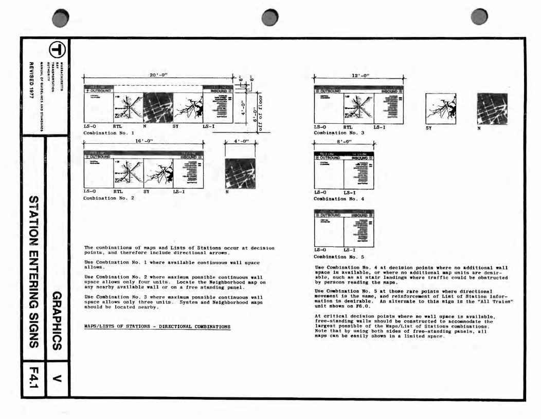
The combinations of maps and Lists of Stations occur at decision points, and therefore include directional arrowe.
Uee Combination No . 1 where available continuous wall space allows .
Use Combination No. 2 where maximum possible continuous wall s pace allows only four units . Locate the Neighborhood map on any nearby available wall or on a free standing panel.
Use Combination No.3 where maximum possible continuous wall s pace allows only three units . System and Neighborhood maps should be located nearby.
MAPS / LISTS OF STATIONS - DIRECTIONAL COMBINATIONS
t 12'-0" L 1
1££&2 MSII
RTL Combtn~tion No . 3
t S' -0" L 1
MF ._~ J!IJI
LS-O LS-I Combination No . 4
Combination No. 5
Sy N
Use Combination No. 4 at decision points where no additional wall space is available, or where no additional map units are desir able , such as at stair landings where traffic could be obstructed by persons reading the maps.
Use Coabination No. 5 movement is the same, mation is desirable. unit shown on F6 .0.
at those rare points where directional and reinforceaent of I.ist of Station intorAn alternate to thie sign Is the "All Trains"
At critical decision pOints where no wall apace is available, free-standing walls should be constructed to accommodate the largest possible of the Maps /List of Stations combinations, Note that by using both sides of free-standing panels, all mapa can be easily shown 1n a limited spo<,e .

continu
PLATFOR1 ELEVATIO
In ationc:: wh r h o . C. , all four map un! ge h r to mak a 16 -0" alterna wi h he map (3 - 4'-0" pi c ) or 1 adequat bench!n hould
name band plu 6" infor ation band
4'-0" map pan 1
9" nam band
on ru tural ba
ruc ural bay i r a r han 15'-f}" (LS, RTL Sy. and ) can b u d 0-
map roup n Th pho omural which roupin may th n b eith r 12'-0" t " ( 4 - 4' -0" piece ) . Room or b lef be we n map aDd pho omura1
If desired the low r band can b u ed intermit en 1y occurrin~ only at maps and photomural. Wh r vi ibili y of th up r band is adequat for prODS on board trains tb lower band may b omitted.
APS/ LISTS OF
CI) ...... e ..... ". ••• t.... . ."aN .. , .". "."1.1 ,,, Of. ."'1..... ,,~.. •.
OF FOUR
GRAPHICS v REYISED "n ST ATION ENTERING SIGNS F4.2

entering circulation entering circulation
PLATFORM ELEVATION
This examp e is dr wn 0 show a frequently encountered condition, a center load d platform with 12 ' bays. It 1s not an accura e repre entation 0 a condition at Kend 11 Station.
Struc ural bay of S ations in roups ture .
pproximatel 1 2 eet dictate three in order to relate 0
aps / Li t of he architec-
If de ired, the lower b nd can be u ed intermit ently, occuring only at map and photomural Where vi ibili y 0 the upper band i adequate for p r on on bo rd train, he lower band ma y be om i ted.
ote , however, tha there ar four baSic un "t required at pIa -orms: the appropriate LS for the platform RTL map SY map
and map . Thi is true for both sides of the ation .
Groups of tbre hould be f rmed as follow RTL always to ether a a pair, and 1 erna and SY a the third uni .
Loc te the LS direc ly under he Station Band. Where po sible, arran e the maps 0 the circulation pattern. The RTL map i mo entering tra !i and hould be seen fir t as train. The oppo ite 1s true for exiting tra sh uld be se n fir as one leave th pIa
~APS/LIST OF STATIO
Keep the LS and th use 0 the
in the ldenti y ha hey rela e 0 t "mportant to one approache the fie, and the m p
orm .
GRAPHICS v
REVISED i77 STATION EXITING SIGNS F4.3
• 8)
~ E ~:;: < : A: : ii " ., n-
!! :: ~ Il! o .. • .... ....
en ~ ,. ~ -0 z m z ~ m :D -z Q til -C) Z cn --n
.. D .. ~ : i a ! ..
Q :D ,. -a ::I: -n cn
~I< ..
•
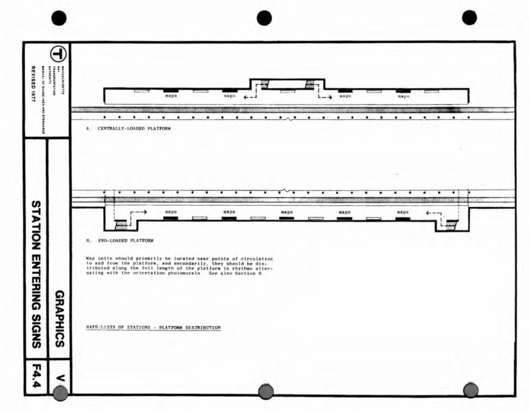
A CEltl'RALlY-I,oADEO PLATfOft
•• p
R • E:lI D-LOA OED PLA Tf"ORIII
~.p un \l~ should prl.lrt" be lora ted nelr potnt. of clrcu'lt i a o and from th~ pl.trora. and secondarl. ,. th~, ahould be d'erllluhd alonlll th ... Jull It'nllth of lho plat fo.ra in r h,lh.1I alter
nlllnt: wIth lhO' orIentation phot_urat. S ... 1.110 5coclion II
~fJ'S J l.I STS OF STATIOSS - PI.ATf'ORIII DISTRIBUTION
•

~ 10" ~ 4'-0"
RED LINE white letters colored field
@INBOUND black letters & arrow on white field
arrow may be omitted when not needed
KENDALL I CHARLES
PARK STREET _._
WASHINGTON '! SOUTH STATION
BROADWAY ANDREW
COLUMBIA SAVIN HILL
FIELDS CORNER SHAWMUT ASHMONT
'''',\;If''f'AN ___ _
NORTH QUINCY WOLLASTON
QUINCY CENTER
Sample Sign at Kendall Station Inbound
" I
The purpose of these uni ts is to allow a passenger to quickly determine the direction of trains to his destination so that he will know which platform to go to. As described on II 1-4.0 of the Manual, the Authority's system is baSically radial, and the platforms are therefore designated inbound or outbound at all stations except at downtown stations where the lines cross.
Standard artwork used for all stations. Station names include the station where this sign is located and all stations to the terminal in a given direction. (Fabricator blanks out screen for omitted stations)
LISTS OF STATIONS - INBOUND
GRAPHICS v REVISED 1977 STATION ENTERING SIGNS FS.O
•
•
•
4' -0"
~ 10" ~ RED LINE
OUTBOUND @
"ARVAR D I CENTRAL KENDAU
• •• •
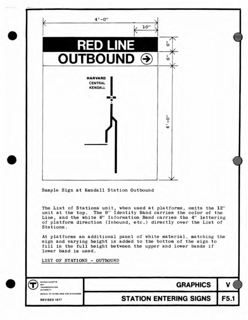
Sample Sign at Kendall Station Outbound
o I
The List of Stations un Ot, when used at pIa forms omits the 12 ' unit a the top. The 9" Iden ity Band carrie th color of th Line, and the hite 6" In fo rma ion Band carries the 4" letterin o platform direction (Inbound, etc. ) directly over the List of S ation .
At plat orm an addition I panel of white m terial ma chi n the sign and vary ng height 15 added to the bottom of be si n to fill in the full height between the upper nd lower band if lower band is u ed.
LIST OF STATIO S - OUTBOU
GRAPHICS .... UAl 01 .... L U. ... I ....
v
REVISED 1877 STATION ENTERING SIGNS FS.1

~ 10" ~ 4'-0"
RED LINE ® ALL TRAINS
HA.AVAR. D I CENTRAL KENDALL CHARLES
PARK STREET _-_ WASHINGTON '!'
SOUTH STATij)N BROADWAY
ANDREW COLUMBIA
SAVIN HILL FIELDS CORNER
SHAWMUT ASHMONT
... " "!, .~,,. ----NORTH QUINCY
WOLLASTON
QUINCY CENTER
--....--
o I
This sign is used where there is insufficient wall space to accommodate separate signs for inbound and outbound, or where a passageway or stairway serves both directions.
A similar sign is used at Green Line surface stops where space and budget precludes the use of special signs for each stop or direction.
LISTS OF STATIONS - ALL TRAINS
GRAPHICS
REVISED 181'7 STATION ENTERING SIGNS
v FS.2
•
•
10"
i RED LINE
(f) INBOUND TO HARVARD VIA WASHINGTON & PARK
3 1 / 2' H 2 1/ 2" min.W
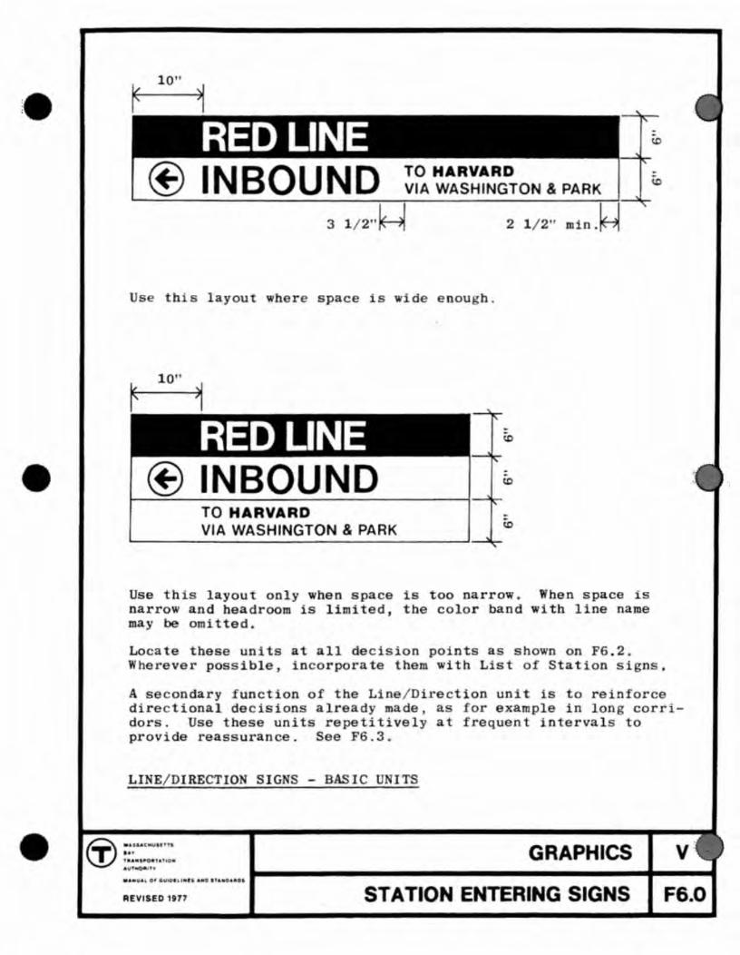
Us thi layou h r space is wid e nou h .
1 0"
1 RED LINE
(f) INBOUND TO HARVARD VIA WASHINGTON & PARK
Use his layout only when pace 1 too narrow. hen space i narrow and headroom is limited, he co or band with line name may omi ted.
Loca e the e units at all decision pOints s shown on FS . 2 . Wherever po sible, incorporate them with List of Station sign.
A s c ondary fUDction of the Lin / Direction uni is to reinforce direc tional decisions already made a for example in lon corridor. Use these unit repetitively at requen interval 0 provide reas urance. See F6.3 .
LINE/ DI RECTION SIG S
(j) .. S-U II: .t ' ... ' o. T ,. .. ,ItO_".t A i '~
... ".0' .". ...., . .. . I'" .....
GRAPHICS v
REVISED 1977 STATION ENTERING SIGNS FS.O

TO HARVARD VIA WASHINGTON & PARK
min. 3 1/2"
Layout for flush right location
RED LINE . TO HARVARD
Layout with single line of small text
OUTBOUND Layout when used with station identity band without List of Sta tions map.
Small text is 1 1 / 2" high, spaced 1" from top and bottom of 6" white band ( f lush with top and bottom of 4" text). Terminal name, "Harvard" , is Helvetica Bold, all other text is Helvetica Medium.
LINE/ DIRECTION SIGNS - VARIATIONS AND DETAILS
GRAPHICS v REVISED 1917 STATION ENTERING SIGNS F6.1

• •
8) :II & ; '" 1 ~ t 1/1
! '" 0 .. ;0 i ... c ...
tn ;! :I 0 z m Z -t m :D - Q z Q :D ,. tn ~ - % Q -Z n tn tn
-." !'»I< ~
•
HJ:AD OF STAIR / nI'O or C'OItRIDOR EI £VAT' O"
811A " COII.R' It n.£VAT I O
... Ih~ LIne D\ r .. c !lon .. llIn ll at clrcu htlnn dpcl"lon polnl~. .h"rt' Iht' "IInlc .. Of IITI. and dlr«tlon h . .. alr .. ady tH. .. " . ad" 0 Ih .. " . .. ,,, o f '1"1 a f li tatl onll1up Unll!! It enlry and Iran" ' "r poillt ..
TIl" al«na .hou ld b" polllilon .. d 'h .. choice .. . r .. clcar and 1101 1 11110n dealln a tlon" .a ",,11 •
the ' r r_ orlenled BO Ih'l UOUI Sho" COli tI nu 1111{ c, rt"ubrallch cl r cul l tlon .
LillI! 01 Rl.CT I OI'! - AT DECtS 10M POII'!TS
•
""rr E- - tr - III J J J.l.l._ .. I .... liIIIIl ,l. i ! ~:
I I I
HEAD or S TA f II or COIUlIDOIl PLAit
I "" I I ----I
i ;.
..... I I I
BRuen COAR I PLAN I
Sr. T6 1 for wl rylo, or •• nl. l tloall of 'lila eaterln. Ind lran-'"rrlna In(or.atlon
Ua. thla dlr.ctlve a t a ll Cho ice". and _""rewer con f u.loa an d disorient ati on alaht occur
per.lta . Include tb" Dlr"cllool l Lift' Ilh lht' Lln,./ Dl rectlon uo ll . The List II I ~ b" .. n pcsus .. In the upper e ... ple a paaaeng"r . Iop
II I I th .. he.d of tha at llra cou ld cau~e conl{""-In til" lo".r ex •• pl .. I".re , .. not adrquI'"
(3) l;I ~ .. 4 ..
~ " .. m " ~ '" < :s " ~ I/)
~ m 0 " <! ... \0 ~ ... .... i ::
'" • " .. :; " ~ g
(f) -I ,. -I -0 Z m Z -I m :II - Q z Q :D ,. (f) "V - % Q -Z ~ (f) -." !,>I< w
~
I l l equal pqual
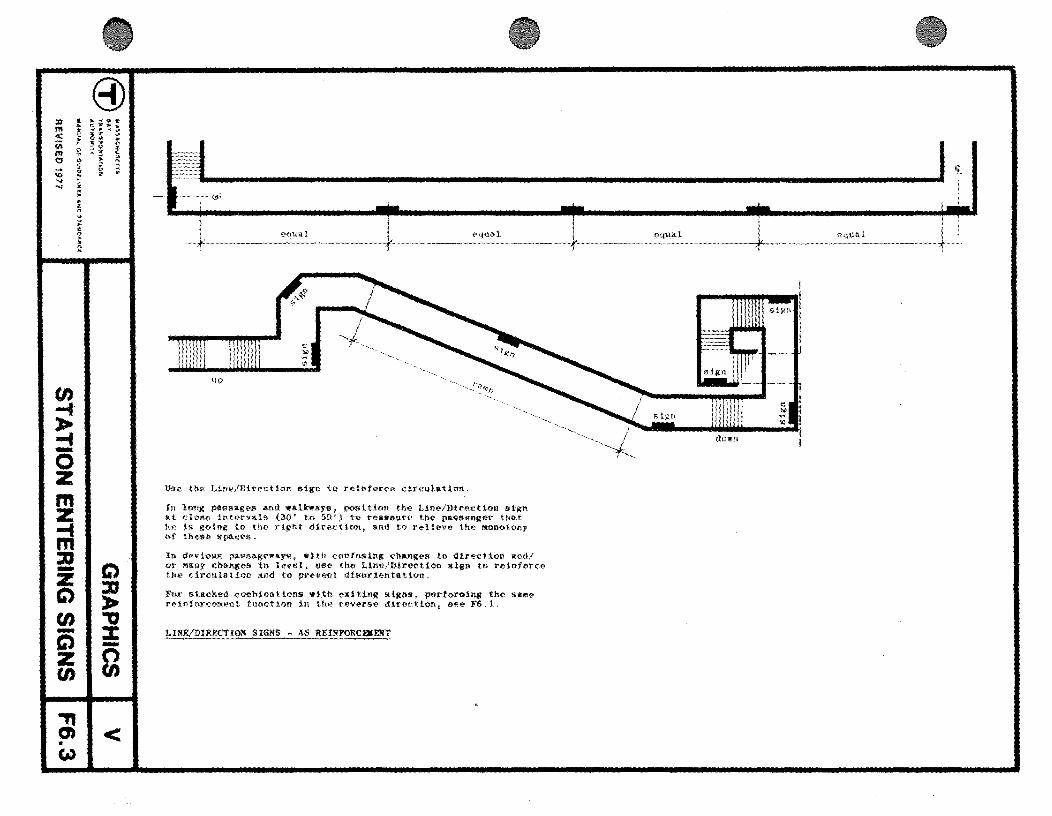
Use U,. LtnE'/Direction sign to reinforce circulation<
In long passages and .alnays. pos1 tion the Line/Direction sign at t: 1 01'1" in tel'vals (30' to 50') to reassure the passenger tlla t 11,·, 1& going 1n the right direction, and to relieve the MOIwtony of these spaces <
In deviouS passage.ays. with confusing changes in direction and'! in level, use the 1,lnl!/Dtrection sign to reinforce and to prevent disorientation,
For stacked ccmbinations wtth exiting siRns, pertor1!ling the sa"'e reinforcement f\!netion in the rev('rse direction. gee FS, 1,
~INE/D1RECTION SIGNS - AS REINFORCEMENT
i
~ equal L equal
down
•
•
ENDAll
--ENDALl
A B
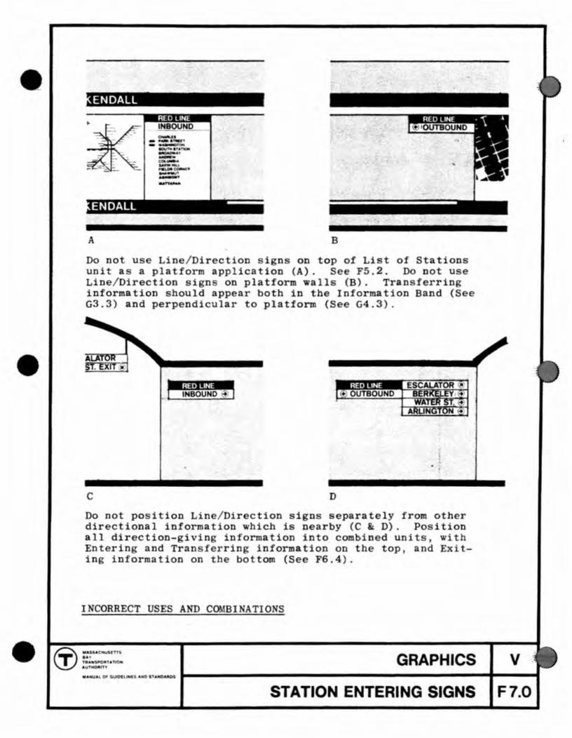
Do not us Line/ Direc ion igns on top of Li t of Stations unit a a platform application (A). See FS.2. Do not use Line/ Direction si n on platform walls (8). Tran ferring information should appear both in the Information Band (See G3.3) and perpendicular to platform (See G4.3) .
• • OUTBOUND
c D
Do not position Line/ Dir ction i n eparately from oth r directional information which i nearby (C D). Po ition all dir ction- iving information into combined unit • with Enterin and Tran ferrin information on the toP . and Ex ' ting information on the bot om (See PS.4) .
GRAPHICS III . ... or G , ' • • T
STATION ENTERING SIGNS
v F7.0

12'-OU
BROOKUNE VILLAGE OUTBOUND "'....,. ......
II 0;:
. , --JEll. I --
schedule case
4" x 4" steel tu'1:>e - black
o I
M I
emergency phone
Type A - 12' unit with maps, schedule case , and emergency phone Type B - 12' unit with maps only Type C - 12' unit with 1'-3" identity band and bench Type D - 12' unit with 1'_3" identity band only
4"
~r
1--!::;.. ~-
B'-O"
--.-tf-- 2 1/2 "
4'-B"
4" X 4" steel tube - black
o I -
00
Typical B' unit with maps Stop Location Sign
SPECIAL SIGN AND MAP UNITS FOR GREEN LINE SURFACE PLATFORMS
GRAPHICS v
R£VISED 1917 STATION ENTERING SIGNS F7.1
'.
•
•
Compr h n ion of h nin ys em, and of i applica ion a ible pOl D r ~ a ion b com i on trac 5 all po
rout and analyz each d ci ion poin for h n ial 1n-orma ion requir d at ha point.
Thi~ sec ion of he ~anual ou ine th typ ocount red by th xi lng pa 5 0 a1 0 encoun r d by th tran f rrin pa
Th exi in nce b in station pIa form from th leav s th ati on.
with th pa d e lerat ng
of ba ic i nio (som of which ar er) .
s n r' view rain, and nd
of a
h h
The arne crit ria tha app ly to nt rio si n appl al 0 to xitin in: maximum vi ibilit and maximum lmplieity. one ential information hould not b includ d , and r f rene
map hould DO be loea ed in narrow eireula ion ar Copy on dir e ional igD should a shor and cl ar a ible.
The n ighborhood map , a un! that is of pecia inter to th xit'D~ pa nger, hould be loea ed oge h r with oth r map
at the platform, at wide passa way and at ar colI etion lobbies. For combina ions of map unit see S etion F .
orien ation photomurals de eribed in S major graphic i ems at the b ginnin of
s qu n , e n in combination with th tation nam th d celerating train .
GENERA DESCRIPTIO
t10n H. ar he xi tin
band from
GRAPHICS
STATION EXITING SIGNS
v G1.0

@ l)' • )0 '-i: .. .c m : :, :! ! < c %.. 'lift
• 0 to' ...
f/) 0 ~ ~ "i ~ ; ~ ~ :
:C ;! ... ... co'" ..0 :II' l! .... .... r .... i
en .... l> .... -0 Z
~ -::::! z C)
en -C) z en -
:: · " .. p
-: • ~
i
C) :D l> ." :z:: -n en
~I< • ..
S IGN TYPt: ICKY
1 , Uppe r and i,ower S a • .,.~ Band" -Statio n Namp
2', Jnf() rmatton Band -Di re(,' tl o na l S igns - Opaqu",
:1 , Ma p s ,, \ P latIn l'"
4 , Djr~ct l onal Signs E,tt ",,,1 Trans fer - Backlit
5-. rd r t:f Cf io na l Sl~'ns Exi t <1nd Trllnb fer Opaque or Buc kllt
6 . Maps Ins i d e :f'ar(> Co ]b:~('ti.on
7 Maps Outside fare Co llectio n
B . Direct i o na l SiGns -Ex it Bnd Trans fe r - Opaq ue Dr Back lit
l- ~ ".~/::
, "'::-..:. />/ ~ ~ <." " .
':~, .
Note : Backli t dire cti o nal s lgns should be us e d a t a ny maj o r dec ision point s wherp a c cent lighting lor t h e Sign canno t be ade(luu trly proYid~d by ot he r m(·an~ .
D I AGRAMMATlC.!L~t!.~:rRATION - SIGN TYPES
\
'V .. i··· .... ,''1 //
I ;

aaae band plu. 6" informa ion baad
19ht teralaed aightllne terl.
9 " Dame band
ELEVAT10 P . TFOR W L
Us the Upper Station ame Band a all s ation. T de ired , th lower band can be u sed int rmittently occurrin only a map and photomurals. her visibility of th upp r band is ad qua e for p r on onboard train , th low r band may b omitted . The .. nam bands occur only on trai and bu pIa forms.
t platforms wh re continuou all surfac do no exis . nam band may b intermitt nt, upport d from the ceilin or by free standin structures . Th ation name mu t e visibl
rom every car in a train.
tation nam i c nt r bay or ev r y oth r bay ac o rd ing to i h lin
h . ation nam on th
d in s ructural ay and oc ur ev ry a hown in G2.1. 2.2. Loca th band crit ria : 1-0 • D.O. Do not ob cur
Low r Band wi h ench
GRAPHICS V
REVISED "77 STATION EXITING SIGNS G2.0

8J ::If t 111' -...: ., _ " c -»,. Pf ... -4 .. ..:
~ ~ I'll o ..... '" '" '"
en
E -0 z ~ --f -z C)
en -C) z en -C)
C) XI ,. " ::z: -0 en
1\)1< • .....
CLOSELY SPACED CDLUMNS ON PLATFOIDI - 8'-16' o,c,
.} -"~+~,- F I Namp : Nam~ <
!
-=--~----~--"~-' .•. """"~~'--•. ~' .-'- "" .--1"""- \ ,-I" ,--'"'''''''''''''''' - I -CLOSELY SPACED CQLU1INS BETW1!:ltlf TRACKS - l:l' - 16' co, e ,
u~('> the aotJv{'- rule-s to locate the stnti.on fHU'f~r.- on band. See 03,0 fur cDcordlnallan of ather graphic
liMIt: BAIIOO/STATlON NMU; - SPACING
col Une
WIDELY SPACED COUJM:NS ON PLATFOIU{ - \7'-24' n.c.
r """-""""""""'t Na~e Name
.1"
WIDELY SPAl~1) l~LUMNS BETWEEN TRACKS" 17'-24' n,c
In stations where the structural with flat Side •• lls, space the ::>2' , 0" n, c"
are apparent, such as those na.1!lHJS III t 24 t .... on (HO

qual
NAME BAND - UPPER
l ., qual
I .., 1
L x
equal
qual
('II
'..... .....
of column bay
A fE BAND - LOWER (i f u d)
Sta tion m 1s 6" hi t rin g ( S tion C or Author-ity Alpbab and Opaqu in Rul on 9" i ld th olor of th line (RTL Se on B) .
Sta ion am i nter d on th n r-11n of th ru ural bay. U ov r pho omural and rnap ~ wh n th y ur. S G3 . 0 .
GRAPHICS V
REVISED 1177 STATION EXITING SIGNS G2.2

~
"' < M "' o ~ ... :;j
en ~ .... -0 Z
~ -.... -Z Q en -C) Z en
(3) • .. "'II! .« .. c · ~ '. • .. . <l1li "'"
~ i ~ i ; ~. I .. 4: :: • S i : . . :i ·
Q ::IJ :. ." % -~
C) NI< • W
S II!(JILI! P LA TTO - AfTl:1I
On. ot the aoat 'aportaat loal. or .od.rataatlon I. to . chlev COnel.tent orient al loa In r.lalloD to lb. full I.nrth a. the train . The e"Hlnl( p •••• n ... r, dl ••• barlllni a' aa, point eloD the rull lenlth or the plat for. •• hould be able to ••• ' .. edlately thn .tatlon oa .. , and read directiona l .altlo, loton-atloa . If po •• lble, and partlCulerly In under,round .t a t l o~. b •• bould al tbe .a.e tt •• be abl .. to •••• reco,nl~.bl. orleat a t l on photo.ural lhal relnfarce. tbe at a t l on'. ldentlt, C ••• Sec t lon R) .
]!!H BAIfDS - I.IIfEAR cotrrl.!!!!!!!
Platronaa that ha.e loa, opea arna. without adequa te lTa phl urra ... th.reror. need additi onal .all aurface . ~.w free
atandlnl ri ll., tloor to c.llin. partitions aad cbeek •• 11 neat to at a lr. sbould be coaetructed a. ladlcated In Ihl8 .~. .pl. (5 •• • Iao Part I) 1I.I.te n •• • • 11 . to the . truc tu~1 .1ste-. In a . aaner eUillar to tbe elation n ... RDacla. S GZ . I .

Do not allow porcelain enamel joints, which are of necessity quite visible, to occur between letters or closer than 2i" to either end of any sign unit. ( See also GS.O).
For fabri cation and ins tallation details, see Section VII.
NAME BANDS - PORCELAIN ENAMEL JOINTS
GRAPHICS v IT' ::r=:: \.!.J . \ITMOAlTT
... .H:U,l\.cwO-..Ot'- 'A.NDI'.ICAIIOI 1-----------------------1----1 STATION EXITI G SIGNS G2.5

Use the Information Band (the white part of the Upper Name Band) exclusively for directional information: direction over station lists (' Inbound"; "Outbound"; 'southbound"; etc. -See F4.2 4.3, 4.4) and exiting and transferring instructions.
The Information Band should only be interrupted where necessary, such as over doorways. The colored part of the top Band should continue without interruptions wherever possible (See G3.2).
Signs within the Information Band must be centered between the Station Names. Do not place directional signs over photomurals unless absolutely necessary.
INFORMATION BAND - BASIC USE
® IW ..... C.HUACTT.
T I" t,.INS'OR"T"no AUTMO-f1Y
GRAPHICS v II.MU.a.L04IO~.lIA"D "&WDA ot 1------------------------... ---"1
STATION EXITING SIGNS G3.0

col. line I
Length of Copy Varies
of bay or of column
col. line col. line
of bay or
of column
I ~
of ba
I
~ of bay
or
col. line
of column
Information Band is 6" white porcelain enamel or polyvinalfluoride with 4" black lettering. For alphabet, spacing rules, and uses of arrow, see Section C.
Directional signs are located midway between Station Names. Avoid locating Directional Signs under Station Names wherever possible.
As shown on G2.l, directional signs may occur halfway between closely spaced columns, or at the center line of widely spaced columns.
Keep copy of signs simple and brief for maximum clarity.
INFOR TION BAND - SPACING OF DIRECTIONAL SIGNS
r.r ~::::: GRAPHICS v '-.!-) AU'T'KCNUff
Ii,a UALOFOUtDtUHaIAWOnAlAlJUlI '------------------------It---"1 ST TION EXITING SIGNS G3.1

The Information Band may be interrupted if necessary. for example over doorways or recesses where headroom may demand it. The colored part of the Upper Band , however should continue at all times as shown above.
INFORMATION BAND - NECESSARY INTERRupTIONS
~:::==N ~ AU'lMQtlln'f GRAPHICS v
....... UA or-Cu,,.,.,UMtaAMO TANQ"_OI �_---------------------~I_--... STATIO ENTERING SIGNS G3.2

•
~~bite letters, orange field
,HINGTON ED LI E@
black letters and arrow, white field~
If at a special location the Information Band must be used for a line transfer sign, because a 12" Line/Directional sign (see F6.0) cannot be located nearby, or in an adequately visible nearby position, the lettering must be black. D3 not use colored lettering in the white field.
INFOR lATION BAND - LINE TRANSFER USE
r:r~:= \..!.J .UTMOIIm' GRAPHICS v
"_LOO~ .. IftI .. ...- ~----------------------... --~ STATION EXITING SIGNS G3.3

ESC LATOR
® EXIT TO WATER ST. r ,
(!>
"- /
1/ , H I' /
10" • If 2 1/2 min.
The above units are the basic modular components of all directional signs and are to be used at all decision paints. They are used either singly, as shown above, or in stacked combinations, as shown on F6.l and G4.2.
The four foot length is preferred, so as to coordinate with standard map units, but larger lengths of even one foot increments may be used when required for copy fitting. Note that sign copy must not be closer than 2i" to the ends of the signs. Signs of odd lengths should only be used where special architectural conditions dictate, such as suspended illuminated signs spanning exactly between wal
Sign copy is laid out according to the Authority's alphabet and spacing rules (See Section C), with 4" black letters on a 6f! white field.
DIRECTIONAL SIGNS - DETAILS
GRAPHICS v
REVISED 1917 STATION EXITING SIGNS G4.0
•
•
•
Even 1'-0" plus I" increments, or special size determined at job .
"i ...... ®_E_SC_A_L_AT_O_R_- _____ ij STANDARD BACKLIT SIGN UNIT (black lettering white background)
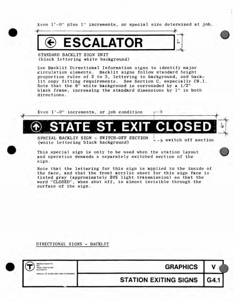
Use Backlit Directional Information signs to identify major Circulation elements. Backlit signs follow standard height proportion rules of 2 to 3, lettering to background, and backlit copy fitting requirements. See Section C, especially CB.I. Note that the 6" whi te background is surrounded by a 1/2" black frame, increasing the standard dimensions by 1" in both directions.
Even 1'-0" increments, or job condition
(1) __ STATE .ST. EXIT CLOSED , I I SPECIAL BACKLIT SIGN - SWITCH-OFF SECTION
(white lettering black background) L -7 swi tch off section
This special sign is only to be used when the station layout and operation demands a separately switched section of the sign .
Note that the lettering for this Sign is applied to the inside of the face, and that the front acrylic sheet for this sign face is tinted gray (approximately 20% light transmission) so that the word "CLOSED", when shut off, is almost invisible through the surface of the sign.
DIRECTIONAL SIGNS - BACKLIT
GRAPHICS ..... '" (n 0
STATION EXITING SIGNS G4.1

1/ 10" '" i" /
EXIT TO WATER ST. @ EXIT TO STATE ST. ®
To combine two sign units , establish reference margin on whicheve r s ide of s ign is required by the arrow conventions, and set lettering to it. See Section C. Separate sign units with 1/4" black stripe centered on the joint between them. Run the black s tripe the full width of the s ign.
V 10"" r--- /
~ EXIT TO STATE ST. EXIT TO MILK ST. '@
Position refe rence margins so that no type overlaps the reference margin o f the sign above or below it. See Section C.
_ .,:1 ••• . ; I 4- ALL TRAINS < I .. EXIT TO WATER ST I FXIT TO MILK S1. ..
STACKED COMBINATIONS
Use 6" black band to separate Line / Direction Signs from other Directional Signs.
Exiting Directional Signs often occur in combination with Entering and transferring informa t ion . In these cases the exiting signs must be located on the lower part of the sign, with entering signs given precede nce on the top. See C7 . 0-9.1 for Arrow/ Circl e spacing, and directions,
Use exiting s igns at all decision paints and for reinforcing exiting circulation. See s imilar applications on FG.3 and 6.4. The same units along pa s sageway walls that reinforce entering circulation should be used to reinforce exiting circulation.
DIRECTIONAL SIGNS - STACKED
GRAPHICS v REVISED 1971 STATION EXITING SIGNS G4.2

8) 1II • • . 1ft • c ! !!: i i fit t : '" 0 • - Ii · ..
~ ... ... i .. · I • • · : : !
5 1
tn ~
~ -i ~ --I - C> Z C) :lJ
l> tn -0 - ~ C) -z 0 fA en -C) .,.1< • w
•
I ~ I I ~r' , , -• - . !
~
AT PASSAGEWAY - ELEVATIO~ 51 AT STA IR - r;I.E\' AT10lt
• L • • ----Sl!:n
• " ...J
___ ..J L __ _
• • • S l ~ AT PASSAGEWAV - PL~ ~IG" AT STA IR - PLAN
Th~.~ ~Ian • • r~ Ihe prl~a,y ~lln . In lh~ ~~Itlnl .equ~"e~. d""II[""d I., lel.nttl, P ...... IIC' .. "V ••• 181, •• and e "e.Utor. fo ,'
h!!' r ..... ,.nll(·r . 'hn h . .. luql dl"_b.rk~d Ir_ IhO' train .
Bae ll - l llu8lnmlltJn .... ·C'''nl
dlllhull Ian Yo
0 1 Rn.:rIO~.\1. 1.1 T A!lD OPAQI1F.
-81 AT C\I..ATOlI -
---, •
•
~.
VAno!l
kilt Ilfn
S IQf AT ESCALATOIt -
---, •
•
ATIO
•
___ .J
• ___ .-l
• L __
• 31 AT tATOR - "LA" S IC!! AT S2SCAtATOIt - PUJ(
!lole thaI tho fl~ld hallht of t heea ella. te 81.1,. 8" or • ('08b ln.ll o n 0 1 6" et rl DS ,,~el"'lve of the tr..., dl.enllon
lIb bl . nk-ol. Opt10D when Itl 'rwa, . an'8.1 closed . Se. IY-DS.3. UnlIke all
.U-I UK" whit e lettarl on 1 bllc ll
a Backlit DIractlonl1 tntoreilion Il,n perpendicul ar t o c lrculat loD 110w to Idlallt, .aJor c ircul .t l o n ale •• nl & .n eho l c~. - •• cllitor , trol18" tranl'.r, etc . S •• I V-D$. 0$ . 1
01 R&t"!' IOIlA I. 1
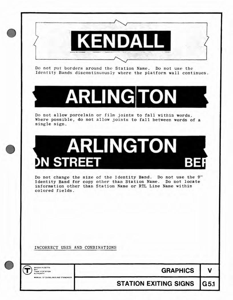
KENDALL Do not put borders around the Station Name. Do not use the Identity Bands discontinuously where the platform wall continues.
ARLING Do not allow porcelain or film joints to fall within words. Where pOSSible, do not allow joints to fall between words of a single sign.
Do not change the size of the Identity Band. Do not use the 9" Identity Band for copy other than Station Name. Do not locate informat i on other than Station Name or RTL Line Name within colored fields.
INCORRECT USES AND COMBINATIONS
GRAPHICS v .... HI,I. I, Q:,:OtllonJNfi' ... O Sl'ANo-A:~D1\ ... -----------------------4~--..
STATION EXITING SIGNS G5j

•
•
•
nderground t ion that lack open views to the n i hborbood are par i ul rly in need of a tron individual identi y, whi h canno be adequately iven by Station me b Dds or minor v riation n arc hit ctural tructure, flnishe , or variou d ails. I i nece sary 0 ive trong and meaningful vari ty 0 the tran it ystem nd e abli h for each station a "sen e 0 pl ce " .
In the irst tation modernized by the Authori y, he photomur I y tem ha pl yed vital rol in the ta ion design nd i p r
ticularly import nt in underground station platform. Thi oncept ha been developed to e tabli h or to rein orce the pecial identity of each tation. Tbe subject rna ter or each photomural bas been drawn from the nei hborhood surrounding the tation in whicb t appears. Since their ima es are photographi C and therefore recognizable reflec ions of each B ation's nei bborhood. the photomurals are more than decorative. They v -ually tell the passengers, a they arrive by train at tbe tation, where hey are.
In a number of instances the neighborhood of the tation was undergoing r dical physic I changes and it was nece ry 0
substitu e copie of old prints or other symbols to visually relate the station to it urroundings. An example is b eball tickets u ed at Kenmore .
Exper~ence ba shown ha i 1 po sible 0 establi h the ttion identity or persons onboard the trains, as well as iving those waiting on the platform a pleasanter environment , with the aid of more abs ract forms 0 public art includin mural and scu lp ure.
Photomurals or draw in normally have been distributed linearly along the plat orm to maximize their impac. As trains move throu h the ation, it is also possible 0 concentrate the work at one, or a e high impact location An example is the steel culp ure a he entering end of he Es ex outbound platform .
The use of public art in other area of the station is u eful in establishin "landmarks" which help to orient the users , a well as improving their environment. An example is the train picture at or h S ation entry .
General Description
GRAPHICS v
REVISED 1871 STATION ART H1.0

G:) ... I: .... tAu ... rn
T IA. lUnJlOI,.r-IOM .",-ott,,1'
"~.U"L 0' 011 O. U ......... nl O ... D.
REVISED 1'71
GRAPHICS v PLATFORM PHOTOMURALS H2.0
• • 8)
:II) ; ; "' < ! (/I
"' ,
0 0 c ... ! ..
..... !: ... l · .. It • · : : · I •
" S ." 0 :1J 3C
" ::t 0 -f C) 0
:xJ i: > C ." ::D ::z: ~ -r- 0 en en
~I< b
• •
PLATfOll1l - ('UITRAI.I.Y LOADED
------~--~---- .~.-----~---~-----~--~ ---~------~---~---~~---~---~~--~----~----. . -----
PI.ATJ'OR" - nm LOAD
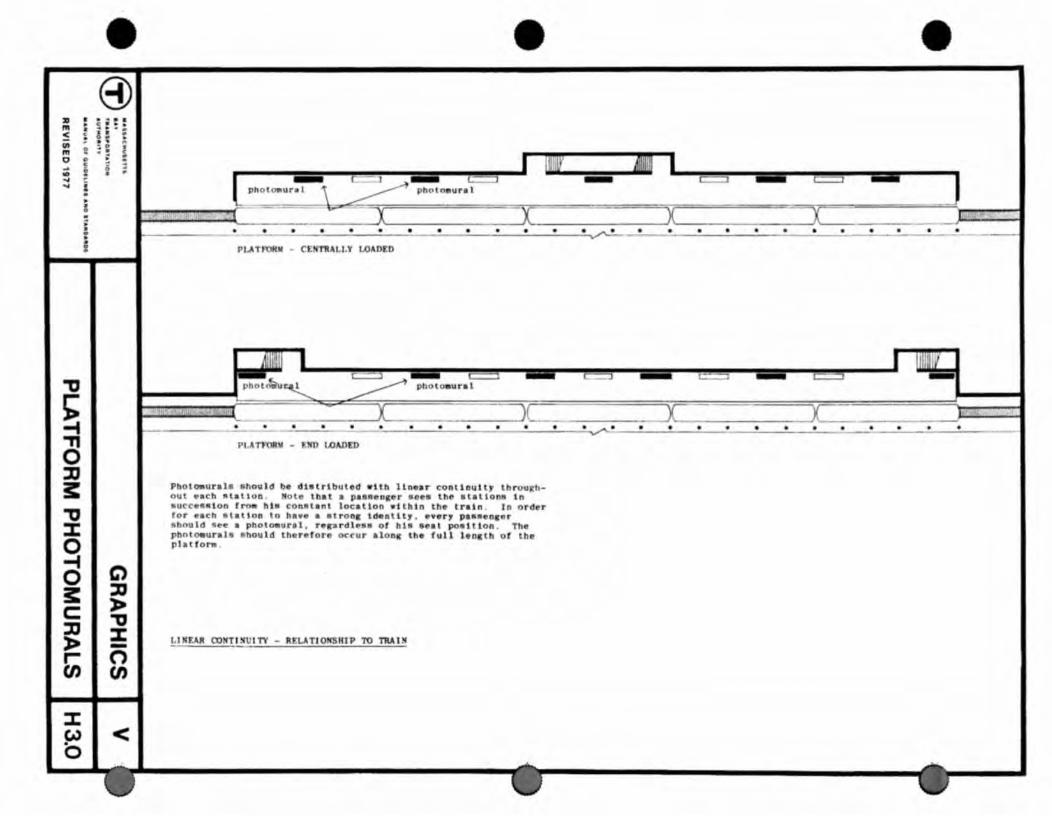
PhotOliurale ahou ld be d1alrlbuted wUh llnen conlillulty th roughout r.el! ~lallun . Male that II p •••• n •• r .oee lh~ elatlon8 In 8ul:C:.lllllon rro. hi. eoruH anl 10c.Uon .-t thin the train . In order ror e.ch etlil ion 10 ha.o a .trone Identity , •• er, palla.nler should ~ee II pbotOllur.l. r.r.rdl ••• 01 h.a e •• , po •• tlon . Th phntOliural. ahou ld ther.for. ocrur alon, tbe tull lenatll of lh. plattora
","UR CO!fT INII IT'i - REl.AT10HSHIP TO l1lUM

8) 2 ~ ....... III .: -...
0 ........ ., ~ c a 0 •
: o. '. lit ~: : III ~ ~ . a • . . - , " : I: 0 . • • .. i ..
I: • , ; • : • .. ·
r
~ 1T
~ -I cg ::D 3: ~ ::t: 0 -4 C) 0 ::D s:: :a:-c: ~ ::D ::t: » -r- 0 en en
-~I< . ~
..lWw..:..
~ • • • a • • • • • . ~ E .....
l ' ~ ) • • • • • • • • • a -
I "I : rf : . ti ,l) • .. ' .. ·· .... ·t '·j! I .1, t !
PLA TFORY "ITlf 1I1!fIIlAL WA LL SU RF"
Pg u,a l l o •
•
.. ptt .. o o a at! o
,.... • • o •
Pt.ATJ'OfUI W'TlI "ALL SU1lFA A oem P'OIt 1.1 IIE.lJl OOlCTllfU I TV or ellA PlIl CS
StatiOD r~u lr au ral ".
.lth .ID1.a l •• 11 .urhc:. oppoelte arr lylD, p ..... nc~r th(' cons truc tion o r additional .a ll. ror • • pt! and photo-
The.e .alle t Ion or t he 0180 l no l ud benchlnc .
. hould be ao located that the, do not block c ircula"'au. ' oponn ••• or tbe IItat lon . Tbe .al l •• hould upper a nd lower .t. tlon Da.e b. nd. aDd CADtllevered
Th • •• 11 • • u. t be dl.tributed alonK the lull lonltb or the pl at l or. &0 that po •• onller. a lllbUDC or .,1 • • 1nl fr_ a ll polDt 810n, the lenath o f the train - Ill be e.p~.d to th
LIKI!AR COlfTlKlnTV - "ALL OOllSTRUCffO}(
i : ~; -: F;'j ~·"" ~ ·' i " II.P.I' T I ! ~J ~rr il; ' :'Il 'ilglIll_lil '~
• a a • • • • • a • J; 3 ','1 ,'
a • a a • a a • • • a
;- "'"il~~-----~~~- -----:--:- ~~ .!·lii' ' -;:J";.
--r;l; '. a Jl1l pho t"ural • • • • • • • 0\
B ~ • 01 a a a • a •
~ f 'i!~"I';ul'I'IlI! ~ -rr
•
'.
•
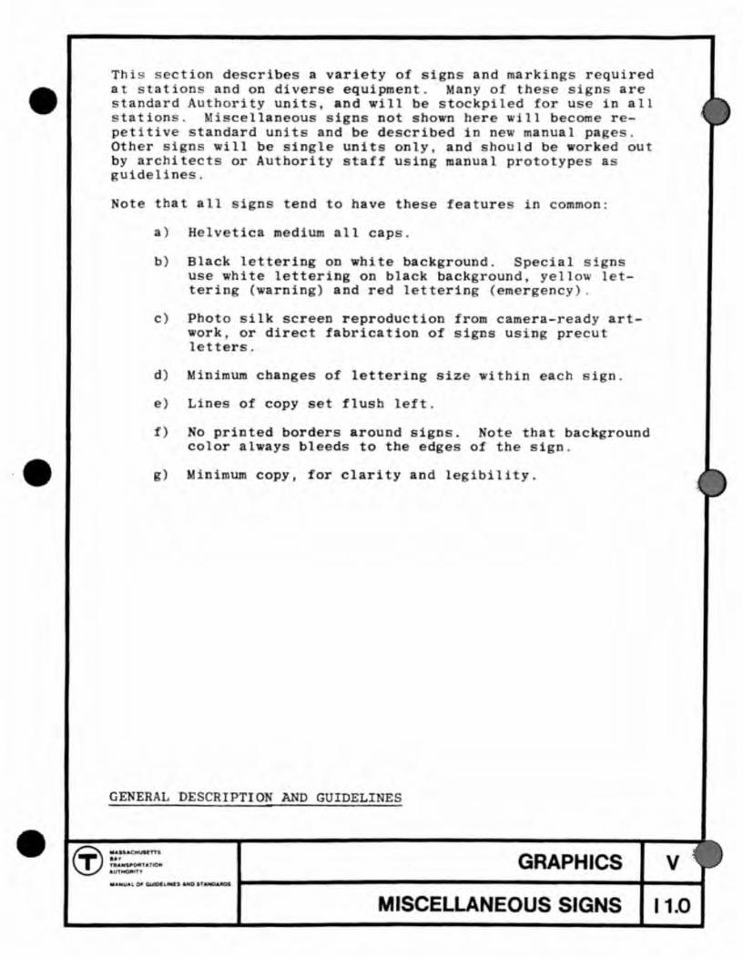
Thi ~ 5 cion d crib a variety of tgn and markings r quired a ation and on diver equipmen M ny of h signs are
tandard Authority units, and will b stockpiled for u in all ta ion . i c llaneou ign not ho n h r will b come r -
petitive s andard unit and b d cribed in new manual pa~ Oth r i n will be in 1 units only and hould be ork d out by architec or Authority aft u in manual proto ype a gUid lines.
ote th all intend to have the e f ature n common:
a) Helv ica m dium all caps.
b) Black lettering on bite background. Sp cial sf n u e white lettering on black background, ye1lo 1 terin (warning) and r d letter1n (m rgency) .
c) Pho 0 ilk screen reproduction from camera-ready artork, or direct fabrication of signs using pr cut
1 tt rs .
d) inimum cbange of lettering size ithin each ign.
e) Lines of copy set flush 1 f .
f)
g)
o printed borders around signs. color always bleeds to the edge
ote tha back round of th ign.
~inimum copy, for clarity and legibilIty.
GENERAL DESCRIPTIO AND GUIOELI ES
9 ~: .r:. \!)" au~· GRAPHICS ... OI'~L"'.
MISCELLANEOUS SIGNS
v
11.0

EMERGENCY EXIT SIGN - 1/16 FULL SIZE
Lettering size: 4"
Co Red letters on white background.
Artwork: Standard Authority Unit
1 GENCY EXIT l:p:
! I
l
1°
ELEVATION - DOOR
Application: Back-lit sign, mounted on wall above or beside door. Include Arrow/Circle if sign must be remote from door.
Material: See Part IV for sign details and materials.
Illumination: Must be on emergency circuits.
Use: Sign should be used with Emergency Exit doors whenever possible.
EMERGENCY SIGNS - "EMERGENCY EXIT" BACKLIT SIGN
® ".$l'AC"YU'n$
GRAPHICS 8" fJlU,H$'PQf£T_1iON AU'I'HOI"HT'f
MANUAl 1)1< C:1.W'tUN't$ A~O $rAJ¢J-"-lI't05
MISCELLANEOUS SIGNS
V
12.0
•
•
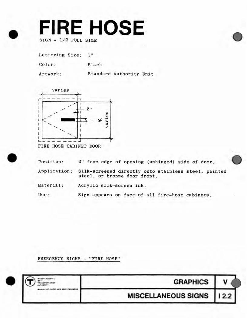
FIRE HOSE SIGN - 1/2 FULL SIZE
Lettering Size: 1"
Color: Black
Artwork: Standard Authority Unit
'-- - - - - --FIRE HOSE CABINET DOOR
Position: 2" from edge of opening (unhinged) side of door.
Application: Silk-screened directly onto stainless steel, painted steel, or bronze door front.
Material: Acrylic silk-screen ink.
Use: Sign appears on face of all fire-hose cabinets.
EMERGENCY SIGNS - "FIRE HOSE"
CT) .... 1; .. ,,&("" •• • 1.... 'fAt ' \IT .....
.. 0#
GRAPHICS
MISCELLANEOUS SIGNS
v
12.2

ga Ivanized steel holder DANGER
NO PASSING
'-----___ ----1-- - --- ---1 SIGN - 1/4 FULL SIZE
Lettering size; 2"
Sign size: 1'_3" x 10"
Color: Black on white
Artwork: MBTA standard unit
o I
M
ELEVATION - PLATFORM END WALL
Position: Flush with the end wall.
Application: Install holder and sign.
Material: Porcelain enamel.
varies
Use: At the end of all RTL station platforms and bus loading areas.
WARNING SIGNS - "DANGER NO PASSING"
® ...... nmstY1$
GRAPHICS SAY 'j'AAfil:twontATtON: AUTt'l(:mt''f¥
MANUj.~, Of{ OUIOltLtN(S ANO Sf.~OARO$
MISCELLANEOUS SIGNS
V
13.0

KEEP BACK OF YELLOW LINE 4It SIGN - 1/8 Ft~L SIZE
4It
4It
Lettering size: 2 "
Color; Yellow on black or dark gray
Artwork: Standard Authority Unit
varies
~
I barrier
\ - - fi=======t;:
track bed
" <L ELEVATION - COLUMNS BETWEEN TRACKS
Position: On Green Line barriers, and on walls and barriers across from bus loading areas.
Frequency: Along the full length of loading areas, one every structura 1 bay', or every 20'.
Application: Silk-screened directly onto painted steel or concrete.
Materia 1: Acrylic si lk-screen ink.
Use: Between tracks and bus lanes . .
WARNING SIGN - "KEEP BACK OF YELLOW LINE"
r.r ~:"~7' ~ a U1 tlIft GRAPHICS v
... h o--~l rt . I ifIlot I-----------------------~t_--_t MISCELLANEOUS SIGNS I 3.1
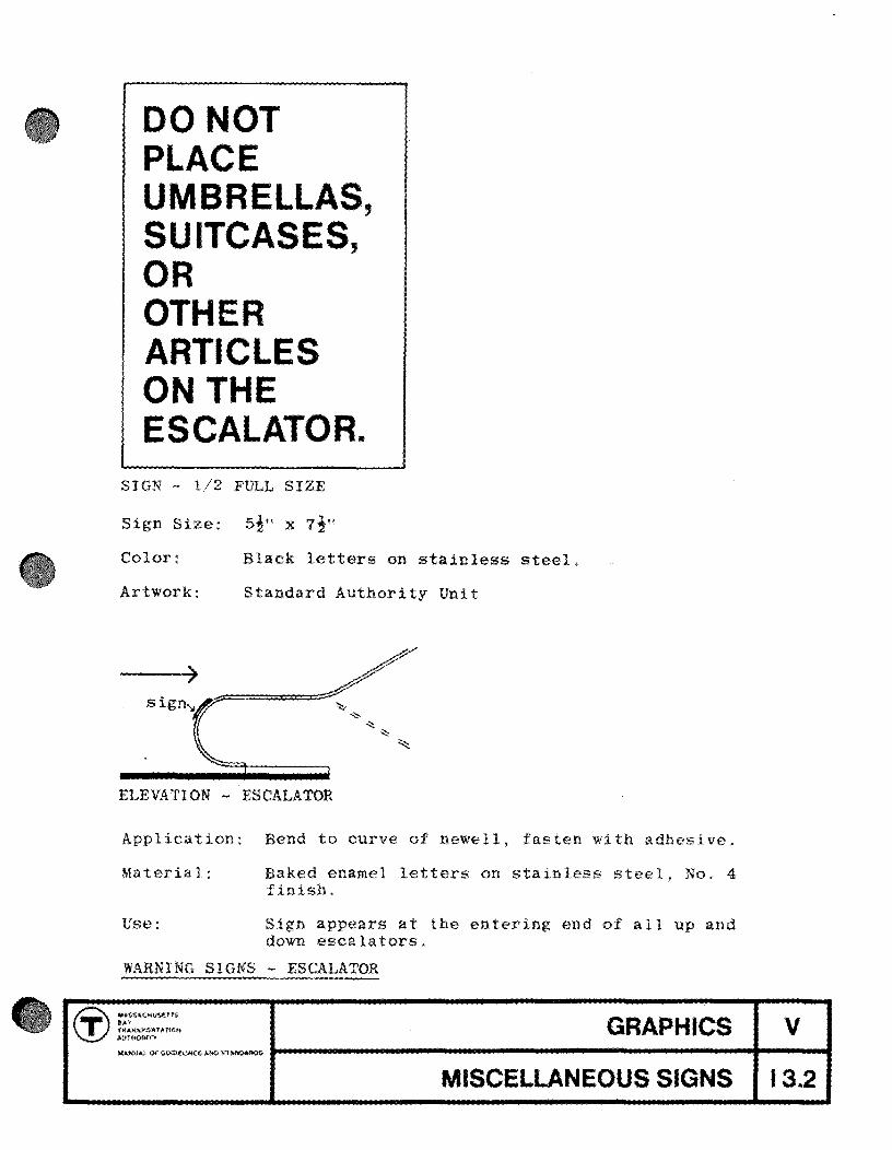
DON T PLACE UMBRELLAS, SUITCASES, OR OTHER ARTICLES ON THE ESCALATOR.
SIGN - 1/2 FULL SIZE
Sign Size: silt x 7i"
Color: Black letters on stainless steel,
Artwork: Standard Authority Unit
Sign".
ELEVATION - ESCALATOR
Application: Bend to curve of newell, fasten with adhesive.
Material: Baked enamel letters on stainless steel, No.4 fini
Use: Sign appears at the entering end of all up and down escalators.
WARNING SIGNS - ESCALATOR
~ ",SUCMusHH
GRAPHICS l!;, .. y T tRA»SP'OfHI,r10trol AU!Hattrf¥
__ a,~UA,t Of (iUfPtUNES j,.uU ~rfA.MO.f\O$
MISCELLANEOUS SIGNS
V
13.2

•
•
•
DANGER THIRD RAIL SIGN - 1/ 8 FULL SIZE
Lettering size: 3"
Color: Yellow letters on black background
Artwork: Standard Authority Unit
sign
STATION - PLATFORM AND TRACKS
Application: Silk screen directly to wall, or use decal of pressure sensitive polyvinyl-flouride film.
Material:
Use:
Acrylic silk-screen ink.
Along length of platform, once every structural bay, or every 20t.
WARNING SIGNS - "DANGER THIRD RAIL"
GRAPHICS
MISCELLANEOUS SIGNS
v
13.3

MEN
WOMEN SIGNS - 1/2 FL~L SIZE
Lettering Size: I"
Color: Black
Artwork: Standard Authority Unit
ELEVATION - TOILET ROOM DOOR - (OUTSIDE)
Position: Over push-plate, as shown, flush right to push plate outer edge, on doors with opposite swing relate signs flush left to push-plate edge.
Application: Silk-screened directly onto painted steel door face,
Material: Acrylic silk-screen ink.
Use: Sign denotes all public toilet rooms when on platforms and all Authority toilet rooms when within Authority-only circulation.
ADVISORY SIGNS - TOILET ROOMS
(:i:) .... S"'.CHWSp .. ••
GRAPHICS lII'< r*t.UIl!'W'(l*lt.'HON .tffjo,fO~lh
.ANt-At. or G;JlbtUHU~ AND $TAlfl)A.JtD$
V
. MISCELLANEOUS SIGNS 14.2

•
•
•
1 10 9 8
7
121 2 3
6 This clock face has been designed using Authority standard numerals and letter spacing for maximum legibility and clarity. It is for use on all clocks within the jurisdiction of the Authority. See Part IV for details and manufacture.
ADVISORY SIGNS - CLOCK FACE
GRAPHICS v
MISCELLANEOUS SIGNS 14.4

® PERSONNEL ONLY SIGN - 1 FULL SIZE
Le t t e r i n g s i z e : l"
Color: Black or gray doors.
Artwork: Standard Autbority lettering and symbol, and standard letter spacing, see sheet C2.0.
II I
I I • -!
2"
I I Ol I i 0 ....-I
I t -
"(!'
,--,1"-
ELEVATION - DOOR
Application: Silk screen applied directly to surface of door.
Use: Identification of all Authority (non-public) doors and rooms within RTL stations.
AUTHORITY FACILITIES - T PERSONNEL ONLY
® "ASSAc"uStrn
GRAPHICS II» r~Affs-p.owr ATI014 AU'tH()'Ui'V
".HI,IAt 0~ -GvIO[l l~fS. .ND ~n ,\NOAA:t)$
V
MISCELLANEOUS SIGNS I 5.0
•
•
•
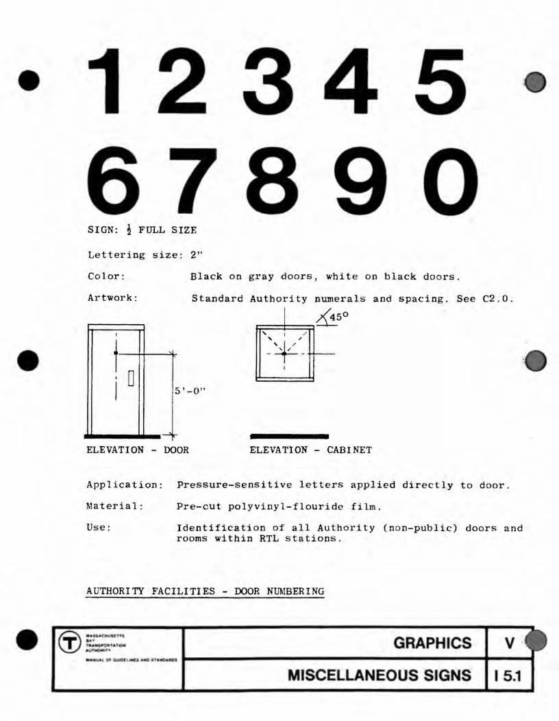
SIGN: ~ FULL SIZE
Lettering size: 2"
Color: Black on gray doors, white on black doors.
Artwork: Standard Authority numerals and spacing. See C2.0 .
I 4 &50
, I / '+/ " / - -I
...... _1 .... _1'-°" ELEVATION - DOOR ELEVATION - CABINET
Application: Pressure-sensitive letters applied directly to door .
Material: Pre-cut polyvinyl-flouride film.
Use: Identification of all Authority (non-public) doors and rooms within RTL stations.
AUTHORITY FACILITIES - DOOR NUMBERING
GRAPHICS v ·
MISCELLANEOUS SIGNS I 5.1

sect of the manual provides gu elines for the control and positive use of revenue ising 1n stations.
uous
It is by ti sinfs + t
ising within stations as a result
the station
hority's ention to can I mHny of the exist
coordinated most can ic-
ver-
more advertis after modernization than t , 11 have
all new stations are t lude it. Adverti becomes a positive element when its gra c impac~ is zed as a major element in the ion design. s when it is lac at
at in conflict with trans information; but in a de i Advertising then becomes an ly cha
exhibition, provld visual animation and pleasure to the Authority's pass s, as well as revenue to the Aut ty itself.
As has been not Section P, ertie panels are t final c element in the passenger's entering sequence, occurr
at that one where he may tave time to enjoy them. Station advertisi should normally be located across tracks ite waiting pass s, who alwuys stand or sit the track. When possible, advertlsinc should be opposite benches.
th tlli:::; > the advertising panels can be seen but not touched by public, preventing vandalism. Advertis
13 are normally not combined with directional signing.
In special cases. advertiSing may be placed station lobbies or pass s if it does not inter with information graphics, arctJitecture ements, and can be protect from vandalism. At sid plat st ions where an er-track structure support of advertis panels ~ not possible, advertis may be combined with information phics on cornmon structures.
The advertis panels to be used consist of two sizes: 2 Sheet with a copy area of 3'_8" x l-l'-lOl! and 6 with a copy area of 5'-0" X 12'-0", These panels can be interchangeably in conjunction with a standard support system which incorporates hanging cl s 3'-0" O.C. horizontal spacing and 3'- l! O.C. vertical spacl The ing system ,'lh;bh may be stand, wallar column mounted, should provide a strong visual framework for the advertis Is, accommodating the two size panels at random. The smallest will s two, 2-Sheet Is or one,
may be I but must be in even mult les of 2-
structure runni between tracks at permit vis iIi.
busy stations, the may a continuous all or most of the p 1 h. When 1 at a s platfor'm stat gaps should be Ie to of one plat from other.
et
GRAPHICS v
REVENUE ADVERTISING L 1.0

•
•
•
For maximum visual impact, panels should be grouped in clusters rather than scattered along walls or spaced widely apart from each other. In subway or fully enclosed stations. advertising panels should have accent lighting. Remote spot or flood lightin is used but care must be taken that lighting does not annoy passengers waiting on the other side of the panels.
For addit iona l general guide lines, see Part I, Guidelines and Principles.
For sample layouts of posters at individual stations, see Part III, Station Modernization Program.
For details of frames and panels, see Pages L5 . 0 to L5 . 3 in this section .
~ENERAL DESCRIPTION AND GUIDELINES (cant-d.)
(j) ::~. ,n, n.... ' 6"01t "u.. t.
GRAPHICS v
REVENUE ADVERTISING L 1. 1
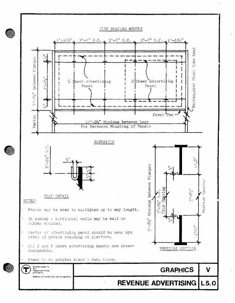
CLIP SPACING MODULE
1 ' o.c. 3'-0" O.C. l'
r--' ---t- • __ ---
S teet AdVerti) TIl: 1 Panel t I •
2 Sheet Ad~ertil' Pane..c
,
12' -8 " Miniml..l.m Between Le .~s For Recessed Mounting of Panels
up to aI'..y
TL StltYw[iY -- b",:riz tC'tEL1, rn,iJ,s may 'be '\-tal1 or '"JltL"':'lL rn< u~jtt3d,..
near eye
6 sheet. adverti. are int.er-
U\
Steel
GRAPHICS v REVENUE ADVERTISING LS.O

•
o I
,.--. . c
'M :s ~
~.~ co
I ~
if\
o I
q I
('\I
('p
~
. t::i) u ;::: . "M 0 0
al
~ p.,
CD ~, -"
I p.,
~y' 'M ,-i U
5:'" --.," J
'"
(i) ..... ,"" ... .... t •
• .." !" .. ...
NOTE: Adv. P8.11Cl..S Mounted On Face of Frame
A;jVERTISING CCr,:EINED WITH PLATFOm< GRAPHICS
r------ -----. --- - - ---I I + + r--+--- --- --F-' I I I I I
I I I I
I I I I 6 Sheet Adv. pan!; I
2 Sheet Aov. Panel I I I I A~)' ts~ Ii
I I I I I ,
I l'-lin. I I ...... (.;,. t .J
I I I
I I I I I t + 1-_-4= __ - - ---t:. _..l I L...-_ -~- _ __ -..J ----- - - - - - -
ADVF,:F{TISING IN NICHE Min. Depth of Niche = "
GRAPHICS v
REVENUE ADVERTISING L5.1
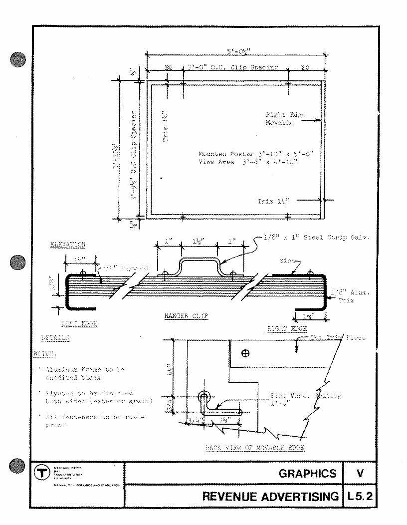
r ...... -
t(,~, finl LL ;,,~jje~) ((.~xterj
".s.~.t~V·iit't'fS ... 1"1t.N~f'U$t~ A TiO'"
t<i' c: 'r'
0-·rl r"; t-;~)
U
CJ
O.C. Cli' S acina
£1 *r->~ ..., [9
Mounted Poster 3'-10" :x 5' View Area 3 t x 4'
Trim
1 X 1" Steel
GRAPHICS v REVENUE ADVERTISING LS.2

E
• ~
'£: l 1r " 12'-0" lVI E-< 'l'r ~~1 t .. ~
t-1 Copy Size r I---'~ • 1 C'
'" t:<l -T-' . . !--' I'"
. • • I U bj)
(\) I . C N
I I 0 .,..j .... 0 0 Ul m , ,..}'" p.. - >, I 0', Ci) U"\ P- I . • I
0
I I I ~ eli
U IV') 'F <"4
C)
Trim
--E-' . • . ---'It" no' r:5,.
~r~ J EQ ~'-O" n f" 3'-0" O.C. 3' -0" O.C. EQ "~ ........ .... IY r
FHC);']' ELEVATION 12!-~" Overall
~ -._ .. --!:tJ c:
'-i U
~ (;\j
~ '" :}:-,j '"'"' (f) m I
," H - eli I (\) (Y' 'M
• - > " ,-<,,\ c + t u
A .-_ . ~ c--
J3'-O" O.C . J EQ o.c . j 3'-0" Q. C. J EQ J 1' _0 1'
r f f rr FRAMING PLAN Hange r Clip:
1" 11' h ~ I 0 "I 1 ti 19.1 )( -'- f 'J >L 1'2 Thick ~~~-----~~--~~
Steel :~~tr:ip 1" X 1" x 1/8" C'+ "'" .• v • Tube Ga1v.
Galv .
"
SECT I ON lJ.. -A h:l.nC.L Face 2L~ Crt . Ga l v . S~h .
NOTE~) : --_. PaintiIJf; - 'rr i r~l u.n d bac k ()1' panel - Black - Semi Gloss Fastenerr; - N<) sor' :\016 Or ri vets a Llo\l{ed on front fa.ce of panel or tri m
' , 0< •• D" t-----------------------------t-----I REVENUE ADVERTISING L5.3


MANUAL OF GUIDELINES AND STANDARDS
PART I GUIDELINES AND PRINCIPLES
PART II STATION RECONNAISSANCE
PART III STATION MODERNIZATION PROGRAM
PART IV COMPONENTS
PART V GRAPHICS
PART VI LIGHTING
PART VII MATERIALS
PART VIII ACOUSTICS
PART IX SERVICE FACILITIES
PART X SITE PLANNING AND NEW STATIONS
PART XI VENTILATION
LIGHTING VI
REVISEO HI14 1

•
•
•
Part VI of the Manual describes the basic design goals for station lighting. It diagrams typical station lighting situations, and fixture types to accomroodate them.
Each Station Architect is responsible for a lighting layout designed in conformance with the Basic Goals, and utilizing, insofar as practicable and unless directed otherwise, the standardized fixture types.
LIGHTING
" VIS 0 ,.,.
VI
2
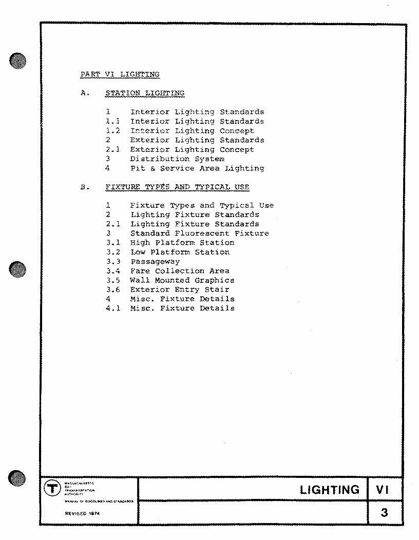
PART VI LIGHTING
A. STATION LIGHTING
1 Interior Lighting Standards 1.1 Interior Lighting Standards 1.2 Lighting Concept 2 Exterior Lighting Standards 2.1 Exterior Lighting Concept 3 Distribution System 4 Pit & Service Area Lighting
B. FIXTURE TYPES AND TYPICAL USE
REVIse!> 1974
1 Fixture Types and Typical Use 2 Lighting Fixture Standards 2.1 Lighting Fixture Standards 3 Standard Fluorescent Fixture 3.1 High Platform Station 3.2 Low Platform Station 3.3 Passageway 3.4 Fare Collection Area 3.5 Wall Mounted Graphics 3.6 Exterior Entry Stair 4 Misc. Fixture Details 4.1 Misc. Fixture Details
LIGHTING VI
3

•
••
•
Adequate lighting denotes well being . It is perhaps th singl most important element in the revital i zation of the subway . Low lighting levels, without appreciable variation or contrast, and mazes of unorganized conduit and unrelated fixtures are characteristic of many ex i sting stations. The following basic goals have been adopted for he lighting design of new and modernized stations.
1. General Illumination
Minimum lighting level in public areas should be twenty (20) footcandles, maintained a floor level.
General illumination should not be designed on the basis of a uniform level throughout the station, but rather wi th variations in level as may be required by the particular station layout.
2. High Lighting of Danger/ Decision Areas
3.
High levels of directed light should occur at potential danger areas (stairs , escalators, platform edges, hidden corners), and at decision areas (fare collection equipment. information graphics) .
Spatial Definition
Many stations have a basic clarity of form that can be emphasiz d by properly designed lighting.
4. Exterior/Interior Trans i tion
Abrupt differences in lighting levels between exter ior and interior should be eliminated.
5. Or ientation
In general, maximum contact with surface features should be carried into the station, in order to maintain orientation to the above ground world. In many cases, it will be possible to open up portions of the overhead to bring natural light into stairways, mezzanines, or even platform levels. Where skylight shafts are used, night time illumination should be provided to substitute for daylight.
INTERIOR LIGHTING STANDARDS
LIGHTING VI
lit VISED ,,,. STATION LIGHTING A1
Differences in lighting levels can be used to improve orientation within the station proper. Intense levels will draw the patron and forewarn him of decisions to
be made.
6. Special Emphasis
7.
Certain orientation features, as color coded walls, or graphic elements, such as murals or advertising, should in most cases be given spe 1 accent lighting.
Elimination Clutter
Lighting installations should signed with layout appearance as well as simple coverage in mind, and conduit should be concealed. In existing stations where this is impossible, fixtures should be designed to incorporate raceways wherever practicable. Exposed conduit runs should be held to a minimum, and definitely located by the Station Architect.
8. Emergency Lighting
Emergency lighting will be required in all stations, located to provide a general level of illumination of 4 footcandles, with concentrations at danger areas.
Existing subway stations should utilize existing D.C. sources, incandescent lamps five in series on 600 volts D.C. and normally energized.
New stations should be provided with a natural gas driven engine/generator for emergency power. Emergency lights shall be fed from panels normally fed from normal power source with transfer to generator on normal power failure.
LIGHTING VI
REvlseo 1$114 STATION LIGHTING A1.1
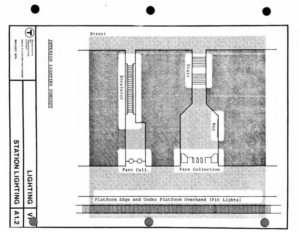
:a '" ~ III
"' o ; ~ i
~
en -t > -t -0 Z r--G") % -t -Z G") -> ~ . N
• 8)
r--G") :I: -t -Z C')
H
~ ~ o ~
t"' H G'l
~ H Z Q
n
~ tx:l to 8
• • Street
The type of lighting and the light intensity will be determined by the function of the area.
Lighting for the pedestrian should in scale to the human figure. Rows of lights may be used to indicate direction or define paths. Light in parking areas should be of a quality and intensity, preferably high pressure sodium, to impart a sense of safety. Self-parking areas and paths require one footcandle of illumination. Large parking areas should be 2-3 foot candles.
Direction and information signs may be brightly backlit for contrast. Surface illuminated sign boards need fifty footcandles on dark surfaces. Backlit signs should be used whenever possible as they are more easily seen at night than surface illuminated signs. Care in placement, color selection, and intensity of light will be necessary to avoid washing out colors and graphics.
Light fixtures should be as vandal resistant as possible, with polycarbonate or high impact acrylic diffusers, particularly those which might be within reach of pedestrians.
Poles should be heavy gauge, extremely rigid, with hand hole and fixed base.
All wiring for exterior lighting fixtures should be buried in plastic coated rigid steel conduit. Overhead wiring will not be permitted.
For large areas, parking, train and bus storage, etc., serious consideration should be given to high mast lighting to minimize number of poles and luminaires. High mast installations should be of type that permits lowering of the lurninaire assembly to ground level for servicing.
Maximum mounting height of fixed luminaires shall be forty (40) feet to permit servicing by bucket truck, where truck access is available.
Ease of maintenance of ~ fixtures is of prime concern.
EXTERIOR LIGHTING STANDARDS
LIGHTING VI
STATION LIGHTING A2
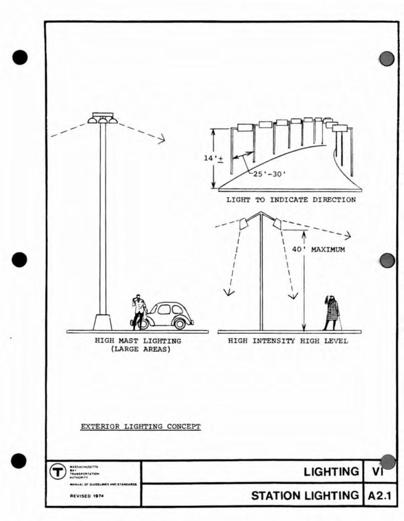
•
•
•
HIGH MAST LIGHTING (LARGE AREAS)
EXTERIOR LIGHTING CONCEPT
14'+
LIGHT TO INDICATE DIRECTION
---I I I I I I I
\V
\-~ --- -~ \ \ 40' MAXIMUM \ \ \ \ \
....v
HIGH INTENSITY HIGH LEVEL
LIGHTING IU. . , 01 UI'C'. a 1AJC)AaDI I-------------------.... ---t "'1115£0 .t,. STATION LIGHTING A2 .1

1. Present distribution system
All station lighting at present is supplied from the Authority's 600 volt direct current lines, run on the tunnel walls. There is one power cable and one light cable in each direction, i.e.! North Bound Power, North Bound Light, South Bound Power, South Bound Light. In event of a power cable failure, the load can be transferred manually. In event of a complete D.C. failure, the light cables are transferred to 550 volt AC at substations to provide emergency lighting. All lighting is incandescent, generally 101 watt, 151 watt and 201 watt street railway lamps, wired five in series. Lamps on anyone circuit are distributed a.bout the station and circuits are apportioned between power and light cable panelboards so that either circuit failures or cable failures will not darken anyone area. This distribution featur~ constitutes the present emergency system.
2. New distribution system
After a review of present power and re-lamping costs, the Authority has determined that new and modernized stations shall have new service entrances, from the public utility, or T traction substation, and that all normal lighting will be on alternating current. In some cases groups of stations will be served by one entrance, and transformers installed to step voltage up and down for distribution within the tunnel between stations.
At new surface stations provide emergency power by natural gase engine-generator sets or other methods; however the difficulty in venting engines and the time lag in shifting over to such an emergency system prohibits its use in underground stations. For the time being, an emergency system separate from the AC normal system will have to be provided, consisting of five-lamp 600 volt DC series circuits as at present. Separate conduit must be provided for AC and DC wiring. Emergency lighting will normally be energized to provide visual indication that D.C. system is operational.
DISTRIBUTION SYSTEM
LIGHTING VI
STATION LIGHTING A3

•
•
1. Pit Lighting
In existing rapid transit stations, there are lights mounted beneath the platform overhang. Lights are incandescent, mounted about 15' on center, wired five-inseries on DC, and are normally O. This lighting is used by work crews and in emergencies and should be renewed as part of the Station Modernization.
New rapid transit station pits should be illuminated by four foot H/O, gasketed fluorescent fixtures,single lamp, mounted under platform overhang on twenty foot centers. Pit lights should be fed from emergency panel boards and should be normally 0 .
2. Lighting of Service Areas
Lighting for other than public areas, public toilets, and built-in collection booths shall be selected for economy and suitability for the area to be lighted. Most service areas will require both normal and emergency lighting .
PIT & SERVICE AREA LIGHTING
••• (i) .... UCMVI~ T ttl ''''1OiI LIGHTING VI . -flE"VISED , e7. STATION LIGHTING A4

The Fixture Use Diagrams illustrate lighting situations frequently encountered in new and existing stations, and show schematic sections of the fixture types which have been selected to meet such situations.
The basic fixture types shown on the Fixture Use Diagrams are commercially available fixtures, modified as may be necessary to meet the criteria for fixtures. Finish is typically baked enamel, matte black color.
FIXTURE TYPES AND TYPICAL USE
LIGHTING VI
REVISED 1"4 FIXTURE TYPES 81

•
•
•
INTERIOR LIGHTING
1. In general, lighting fixtures in new and existing stations should be located to minimize their number and bulk. General lighting should be fluorescent. Accent lighting should be High Intensity Discharge (H.I.D.).
2. Accent lighting should occur only at graphics, danger and decision areas, and other special emphasis elements.
3. In both new and existing stations, certain lighting can be controlled by time switches for use only during peak hours or can be controlled by photo-electric devices when daylight falls below minimum levels.
4. It is expected that certain less-busy existing stations will receive little or no new lighting treatment. In these stations the existing normal and emergency DC lighting system will remain, with perhaps new fixtures substituted for old.
5. Fluorescent fixtures in public areas shall use "warm white" lamps.
6. Incandescent fixtures shall be kept to an absolute minimum.
7. In high ceiling areas fixtures must be mounted at height that will permit servicing and relamping without scaffolds or stagings.
EXTERIOR LIGHTING
1. All exterior lighting should utilize H.I.D. lamps, preferably high pressure sodium, wherever possible, for most efficient energy use.
2. Poles for walkway lighting shall be fixed base type with handholes and shall be of heavy gauge and rigidity to withstand extreme vandalism.
3. Fixed poles for large areas, parking, train or bus storage, etc., shall have a maximum luminaire mounting height of forty feet, for servicing by bucket truck, where truck access is available.
Serious consideration should be given to high mast lighting for large areas to minimize number of poles and luminaires. High mast installations should be of the type that permits lowering of lurninaire assembly to ground level for servicing.
LIGHTING FIXTURE STANDARDS
LIGHTING VI ......,. o. G ", .... , .. -,110 , . AfIlM 1-------------------------1---....
FIXTURE TYPES 82
In general, lighting fixtures for use within the Authority's environment should satisfy the following criteria.
1. Fixtures shall function as effective lighting units for a minimum life of 20 years under arduous conditions of weather, vandalism and vibration.
2. Fixtures shall be enclosed and gasketed, wherever possible, to operate effectively in an atmosphere containing sticky abrasive brakeshoe dust, which tends to foul lampholder contacts and makes cleaning of fixtures and their reflective surfaces difficult without scratching, and at a temperature range of -20° to 90°F.
3. The support and installation of fixtures in long continuous runs shall allow for expansion and contraction in an ambient temperature range of -20 0 to 90°F.
4. In general, through wiring shall be carried in raceways external to the fixture, permitting fixture removal without cutting of wires.
5. Methods of installation should be thoughtfully prepared to accommodate a wide variety of job conditions such as irregularities of wall and ceiling surface, and to minimize errors by untrained personnel.
6. Parts, lamp types, and lengths should be standardized to the greatest extent possible.
7. Non-corroding metal should be used, with adequate protection against galvanic action between dissimilar metals.
8. Replacement of lamps and ballasts should be easily accompl.:i,shed.
9. Where open cylindrical fixtures are used, they must be vented at top for heat dissipation.
10. Use of incandescent fixtures shall absolute minimum.
kept to the
11. Fluorescent fixtures should be tightly gasketed to prevent dust infiltration.
LIGHTING FIXTURE STANDA ~
LIGHTING VI ......... ()<(W!ot:"""' •• ""'''''''OJIt>. I-----.-------------------~t_--... REVISEO 11H4 FIXTURE TYPES 82.1

•
•
l
\
SECTION A-A
,a;j.f t JI.!f t'1"(" ItN -_."" .............. .
SIDE VIEW
.{~;QQ-"" ''''', •. It(1J¢I:! , "' .. _ J.itlh'll..., /""e 1tte.1. ! j
, !
i I
!
-4--!)th!t, A-a'-~n»t!y 1i.~.1't
/ ~(f~!:f'';~. k~: .. ';itf! , Cp'''"' Po .. ificn
SECTION 8-'8
..J:h>q.r J>4 .. t!-~/)"'I A..:tym,,",;>r1t;- :.,.q"'H~ (:$'.# NQf~ n·
NOTES: J; ;; ... ~ A~~tf'"~~,-'~* :/1»1/1 «,,~ Inft--"'f'·-1;.)"H"t!'.(>/~,
~ t"Pfp..o fIt!"<t!'.t;Y~ A3 .. ~~/,.,t!"f1 ;J ~J"1h-~t 1"I0"'*4!"" "-'Y4lrr ,!Ort/!!!t/""9 3lto/! .lie
:zJr~'ff~. lI"n;'1' r.h,'O«,d 4:1 7)? ..... 4IV'~111'~ <if)" I'1iIT"fGlItI';on rt:t_.r7~".t:lor_
., $ __ .",.~, ,..um. r;:,t."rtl $"-".' ~, .$/I'n/J •. "" , fa
:~~~7~!:.h::2~"t;~~ ~~~f:;~~~r l"'~:'7t~~tc" C't"'1"1ftt,... Jll"'I.d '~II' .lII$AII •• tUb>ttIO.n ,,11'1,(':'fo.,-
:t 'i,/v""'« Zli""r".'."'$ AFr ApfII"''''''O';''''.'., ,.".,.1 P-'A'rfIf''1aJon. 8ft./! .; ~.""'iI,.d .......... r;'f*,,"fUI'tIII~w "'p!,r'"OY#IIj,
TYPICAL LIGHTING FIXTURE
STANDARD FLUORESCENT FIXTURE
... """"'. U ' fIl.&lf ' ."-6JIt~lt ..
.. 1 00
t~o SCAlf)
LIGHTING
FIXTURE TYPES 83

......
Fluorescent pit lights, optional location determined by other equipment installed under overhang.
CONTINUOUS FLUORESCENT STRIP
Continuous or intermittent ceiling mounted fluorescent strip, cutoff at platform edge by use of asymmetrical lens. Emergency lights integral with fluorescent strip.
FLUORESCENT PIT LIGHT
4 foot single lamp H/O, enclosed and gasketed fluorescent fixtures mounted 20 ft. on centers
HIGH PLATFORM STATION
"''' ... t.'''OftfAT'OH .Ult4iOJll~n
LIGHTING VI ~ ~ . • '§AC~uSl 'f f$
........ u.t Of. QUIOI\.9illlo AND IU:JrfQ.~O' 1--------------------------+----1 REVISED H11" FIXTURE TYPES 83.1

•
CONTINUOUS FLUORESCENT STRIP
C n inu u u ' p nd d a pIa orm d I n gr:l1
LOW PLATFORM STATIO -. LIGHTING VI
FIXTURE TYPES 83.2

Symmetrical
................................ ... ........ ....... .. . ....... .. .. .. .. .. .. .. .. . .. .. .. . .. . .. .. .. . . .. .. .. .. . .. . . .. .. . .. .. .. . .. .. . .. .. .. .. .. .. .. . .. .. .. .. .. .. .. .. .. .. .. .. .
••••• 0 .......................... .. ...................... ...... . .... ....... ....... .... ... .... ....... ... .. .......... ............. . .. . .. ... .... ....... ...... . ......... ...... ...... ........ ......... . ••• • ...... ••• ......... O . ... ........... ....... .................. ...... . .... ... .... ...... .. . ..... ...... ............. ...................... . · .......... .... ....... ... .. ... ..................................... . .. ....... ..... ...... ..... ...... ........... .. . ........................ . •••• ••• O .......................... ... . ............................ . .. .. .... . . .... .... ... .... . . .. ....................................... . . ' .. .... ... ....... ... ..... ..................................... . ..... . .. .... ... ...... ........... ...... ..... .... . ................ . .... ... .......... ... .. .... .. .. ................................ . .... ..... . .... .... ... . ....... ................... ............... .
I ....... . . .............. . ............................................... . . .. ... ... ..... ... ..... ........... .. ........ . ........... ....... .. · ......................... .. ...................... ......... . . · ............................... .................. ... .............. . ........... . .......... .... ........... ..... . .......... ....... . · ... .. ...... .. ...................... ..... ................. . .. .......... . .. ........ ...... . .. ...... .................... . ... ....... ... ....... ........ ... ... . .... .... ........ ..... . · .......... ..... -..... ...... ...... . .. ........................ . · ................................................. .. . .. .... .... .... ...... ..... ... ........ ...... ... ......... . .. ... ..... ... ....... ... ..... .... ..... .......... ... . ... .......... ... .... ........ .................. .. .. , ..... ... .... .. ......... ..... ........ .......... ...... . ... .. . .. . .... ... ...... ........ .. ... ............. .... . .... ......... ....... ..... ... .. .. ............ .... . .... ............ .... ... ........ ............... ... . .. .... . .. .. .. .......... ..... .... ...... ....... . .. ... ......... . ... .... ...... .. .. ............. .. .
Continuou s Fluorescent Fixture
Symmetrical fixture for area lighting.
Asymmetrical fixture for wall wash.
PASSAGEWAY
. ................ .. ..... ... ........ . . ........... . .......... ............. ... . . ................. .. ..... ............. . . ....................... ........ . ....... . ..... ..... .... ...... ..... ...... ..... .... . . ............... ..... .. ............. . • ............ ... O' ... . ................ . . ................ .... .. ........... ... . . ........ ........... . .............. .. . . .......................... ..... .... . .. ...... .. ................. ... ..... .. . ......... . ... . ... ............... . . ....... ... ......... .............. . . ....... ...... .... ... ..... ' .. ' . ....... .. .... .... ............. . . ......................... ...... . . ....................... ...... . . . .... .... ..... . ....... ....... . . ... ....... . .... . ........... .. . .. ........ .............. . . .... ....... .............. . .. .... ........ .... ...... .. . . . ... .. ................ ... . . . ..... ......... ...... .... . . ........... . ............. . . ....... . .. .. ... . . . ... . . ...................... . .............. , .... . . ... .. ........... . . . . . ~ ... ............ ~ .. . . . ... . . ........... . .
LIGHTING VI M.aHYA~. O' O' u~OU._a.MC'l.NO...,.O& I------------------------... ---l REVISED 1117<4 FIXTURE TYPES 83.3
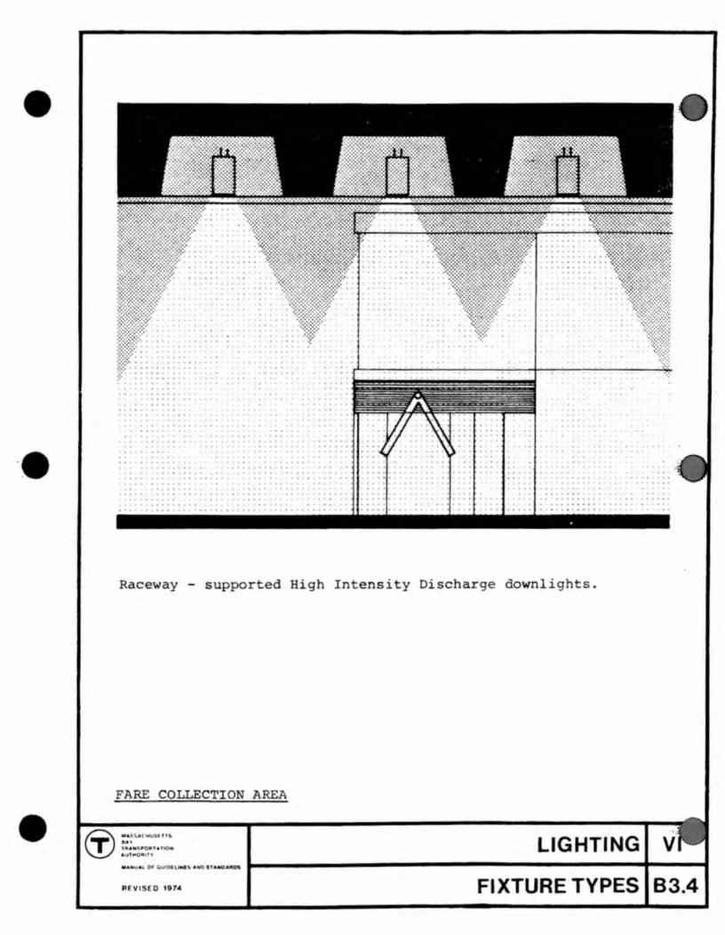
•
• Raceway - supported High Intensity Discharge downlights .
FARE COLLECTION AREA
• LIGHTING
P \11 0 11m FI XTURE TYPES 83.4

Raceway - supported High Intensity Discharge wall washer.
Blanked out reflectors as required.
WALL MOUNTED GRAPHICS
LIGHTING VI IIIIAtrtU;' l 0' Q.UIt)( \-*U-"NOnAHO .. "Dtt 1------------------------1----1 REVISED 1014 FIXTURE TYPES 83.5

•
•
• Combined illuminated sign and fluores nt stair fix ure. In gra1 mergen y 11gh
EXTERIOR ENTRY STAIR
••• (f) "&A ...
T ' .. .-...0.''''' . " LIGHTING V
83.6

1 " , 1 ' 1 ' ,H T.\' , H' P ~ a ~ t 1 C 7' 1 g 11
1 <1\'(' ma~~kpd and pai n t(:~d -~~,~~,~ .... on insid""urtacp,
.\. C. F j UOl'csccnt
Condu:it carried up into sign unbrokHl run from remote pullbox
D. C. Lamp (Emergency) (Existing Stat ) -----"-.
A.C, Flonrescel't 1
A.C. & D.C. Conduits behind finish surface.
Manufacturer's and underwriter's labels to be located inside of fixture.
Station I
II H 0-.1 !l .. ' I II ,.... 1
II 11 if q II II
It, , tl , '
H
SIgn inter.i.or .i.s schematic. In dimensions and appearance, this sign lighting fixture is a standard component with no variations permitted.
Fluorescent: 800 rna, full width of sign Incandescent (emergency, D.C.): 2 - 151 watt, 600 volts, wired f)- i n-5E1r i es. (Existing Stations)
MISC. FIXTURE DETAILS scale 1~" 1'- 0"
LIGHTING VI
84

•
•
•
tail
A K
1/ " xl" x
L ELI G
co DUIT , STUBBED UP
1 / 2 " GROUT -------/
tJ ',' 'LJ 110 .
, 110 , t::' . 11 <::' Olla ' CJ . II .'
II
0:
:;. 0 U
~
til l-l 0 ::r: 0 z ~
~
t:.l f-o <: ...l
L tile:: <:0 mf-o .
Uti) - <U Oe::f&l
f-oo. OZVl t:.lO
3 Ul4
~>z CXl < ...:l
~f3o. .... ::c_ ~tIle--....... -ZZ t,:)e::p:: H::>t:.l tIlc...o.
4 -3/ " IA. x l ' 3" A CHOR ---l---W-----~.J_.-==:._
<1 C)
BOLTS WITH 4"HOOK
2' 0" x 2' " CO CRETE FooTI G~-ABLE TO RESTRAI APPLIED fOMENT 0 250Ft. Lb .
ELECTRICAL SERV ICE
2 - #12 WIRES, 1 - 12 GROUND WIRE, OR LARGER , DEPENDI G ON LENGTH OF RU .
60 HERTZ - A.C. VOLTAGE AS RE UIRED .
T SIGN BASE
MISC . FIXTURE DETAILS
IT' ~=:... .. ;::. LIGHTING
:
J
~.&.""TT" .. 01'0 ~_ • • " ........ L-----------------------+----t flEVI D ,.74 84.1

o
o
o
MASSACHUSETTS BAY TRANSPORTATION AUTHORITY GUIDELINES AND STANDARDS PART VII MATERIALS REVISED 1977


· MANUAL OF GUIDELINES AND STANDARDS -PART I GUIDELINES AND PRINCIPLES
PART II STATION RECONNAISS~~CE (Discontinued)
PART III STATION MODERNIZATION PROGRAM (Discontinued)
PART IV COMPONENTS
PART V GRAPHICS
PART VI LIGHTING
PART VII MATERIALS
PART VIII ACOUSTICS
PART IX
PART X
PART XI
SERVICE FACILITIES
SITE PLANNING AND NEW STATIONS
VENTILATION
MATERIALS VII
1

•
•
GENERAL INTRODUCTION
The Massachu tts Bay Transp~rtation Au hority has ne ssary ~nd poss ible to oncentrat att otion on n eeds of peopl. Programs to improve s rvic u t newemphasi on he qual ' ty of he transport tion eff ct, transpor ation en ine ring has b en joined n ring and nv ' ronmental design.
found it both he complex
now lnclud a xperi nce. In by human n i-
This manual provides a framework for th continu d coordination of all tho eleme nts in the sys tem that aff ct human comfort.
'any of he crit ria involved are common to all nvironme nts, such as the control of light, nois , humidity, e~perature, wind, and odors, or the ne d for orderliness, through cl ar and easy circulation and cl an appe ranc. Other criteria that are or specific to the transpor ation environment ar such n e ds as safe y, traffic handling capability, spatial variety, consistently available information, and ori ntation.
The most important singl tion of this manual i th not only be physically co iul s sens wher he is
criterion that bas gu'ded the praparaneed for ori ntation. The rider must
fortabl , he must also know in the and where h is going.
Since 0 th layman a public transpor ation syste~ is 0 a large extent an invisibl skeleton of the city and metropolitan region,
h compr hension of that truc ure generates an awareness and appreciation ~f the city i elf, and an apprecia ion of travel throu hit.
There ar many asp ts to achiev ' ng this orientation . Circula ion at all pOints mus t b d ' r and open . Spac s should relat vi-sually to th ir surroundin environment, either through dir c openings to adjacent spac s and structures, or in the case of platforms, by graphic refl etion through pbo ographic murals .
Above all, th ne d for orientation places great emphasis and a cons istent system of identification and dir ctional Graphi s then merges as a major factor in he de i n of environmen , a factor that must be given high priority in arly design p~ases of ach project.
on map sigo ' ng, ach the
It is hop ed that all par icip nts in all prog rams will familiari~ the ms e lv s with th ntir manual, so tha th implications of each deciSion can b unders tood in a system-wide conte xt.
The standards and guid lines pres nted b re are no inflexible rules , They ar a fram e work for meaningful development and variety, and off r n~ ,rastric ion 0 the capacity of each partiCipant to evolve bet r solutions to old or new problems.
As new solutions are dev loped and approved, revised and additional pag s for the manual will be issued to all participan s .
GENERAL INTRODUCTION o
1

Part VII of the Manual establishes standards by which materials and finishes proposed for use in the System will be judged. It lists a number of materials and finishes which have been already approved, subject to review by the Director of exact specifications and area of intended installation.
This part provides information on materials and details in use for standardized wall elevations, built-in graphics and other repetitive elements, and includes design standards for the printing of modernized and yet-to-be modernized stations.
For detailed layout requirements of graphic elements, refer to Part V, Graphics. For information regarding acoustic materials, refer to Part VIII, Acoustics. For laterials requirement in specific non-pUblic rooms, refer to Part IX, Service Facilities.
INTRODUCTION
MATERIALS VII
2
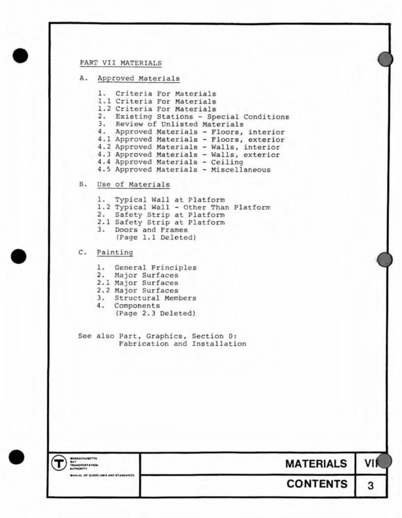
•
•
•
PART VII MATERIALS
A.
1. Cri eria For aterials 1.1 Criteria Fo Ma eria1s 1 . 2 Criteria Fo Materials 2 . Exis ing S a ions - Special Conditions 3 . Review of Unlis ed Materials 4 . Approved aterials - Floors , interior 4 . 1 Approved Materials - Floors , exterior 4.2 Approved Materials - Walls, interior 4 . 3 Approved ateria1s - ~a11s , exterior 4.4 Approved Ma erials - Ceiling 4 . 5 Approved Materials - Miscellaneous
B. Use 0
1 . Typical Wall a Platform 1 . 2 Typical Wall - 0 her Than Platform 2. Sa ety S rip at PIa form 2 . 1 Safety S rip a Platform 3 . Doors and Frames
(Page 1 . 1 Del ed)
c. Painting
1 . General Principles 2 . ·ajor Surfaces 2 . 1 Major Surfaces 2 . 2 Major Surfaces 3 . Structural Memb rs 4 . Componen s
(Page 2 . 3 Dele ed)
Se also Part , Graphics , Section 0 : Fabrica ion and Ins ' a11ation
MATERIALS VI
CONTENTS 3

It 1s the intent of the Authority to utilize materials and finishes throughout the System that will satisfy necessary standards of safety, durability, maintainability, and economy, while at the same time contribute substantially to a station environment that is, in fact and in appearance, clean, dry, odorless, well-lit, physically safe, as quiet and as co~fortable as is reasonable consistent with station function, and above all, that affords a basic clarity of station form and user orientation.
The following criteria pertain to materials and finishes used in public areas only, including public lavatories, built-in collection booths, and service rooms into which the public can normally see. Materials and finishes for service areas not normally exposed to public view shall be judged solely on the basis of economy, and suitability for the use intended. See Part IX for functional requirements of lavatories and other service facilities.
Criteria
1) Safety
In general all materials and finishes used in the system shall be incombustible, although certain minor elements may be of WOOd, rubber, or plastiC. Plastic or rubber materials used over any significant area shall be of a composition that does not support its own combustion, when in place.
All materials and their attachments shall be designed to adequately withstand normal operational vibration, the effects of aging, and espeCially the extreme demands placed on Authority property by theft and vandalism.
Materials and finishes shall be selected that provide adeqUate slip-resistance, glare-reSistance, and other qualities that recognize the frequent presence of crowds, and of the handicapped and infirm.
2) Durability
Materials and finishes Shall be used that provide long useful life, without decay, corrOSion, weakening, decline in appearance, or other failure under normal conditions of use.
CRITERIA FOR MATERIALS ----_._----
MATERIALS VII
APPROVED MATERIALS A 1

•
•
3) Maintainability
Specificati on of mater i als and finishes shall recognize that frequent high quality maintenance cannot be depended upon; and therefore materials with impervious surfaces that resist soiling, and, having been soiled, that tend t o hide the soil, will go far to counteract deficiencies in maintenance. By the same token, materials and details that complicate cleaning ope ration, or which provide unnecessary surfaces to collect dirt, must be avoided. Joints between units shall be minimized, and made of the most durable materials.
Specific soiling conditions include:
Airborne dirt Tracked-in water and dirt Tracked-in salt (in winter) Greasy brakeshoe dust from train Water brought in by wet trains Materials discarded by subway users Many varieties of Vandalism
Materials should be specified which, in event of damage, can be repaired or replaced without untoward disruption of station function, and without calling attention to repaired areas .
4) Environmental Effects
Materials and finishes shall be sele cted for environmental effect as seems most appropriate to the Station Architect; subject only to the following two requirements:
a) All colors shall be compatible with the Authority standard color coded graphics.
Walls and ceilings shall, in general, be light in tone, in order to decrease lighting costs by increasing reflectivity.
b ) Certain repetitive station elements are required to be of particular materials or colors, in order to lend unity to the System as a whole, to solve particular functional problems, and to permit large scale purchasing. These elements are described under this Part Seven, and include the following:
CRITERIA FOR MATERIALS
~ .... W~ .. MATERIALS VII
APPROVED MATERIALS A1 .1
5}
1. Platform 2. Doors and
For and Part
strip (Sheets C - 2 and C-2.1) (Sheet C - 3)
s, see Part Four: Components
Each mater and finish proposed use shall be subject to an informal cost benefit analys I which will equate
in criteria 1-4 above, with its term costs.
CRITERIA FOR MATERIALS
MATERIALS VII
APPROVED MATERIALS A1.2

•
The criteria listed for materials and finishes pertain to both new stations and to modernized existing st tions; however conditions in existing stations may preclude use of certain of the approved materials.
1) Space limi a ions: In many cases, exis ing corridors , stairways, and pIa forms will be found to be too narrow to accommoda e new facing materials of any significant thickn S5. The heigh of pIa form above op of rail a existing sta ions being remodeled mus be held as close as possi Ie to the Authority standards . This res ricts selection of floor finishes in cases where platform structure or track elevation cannot be al ered.
2) Seepag: In some existing stations, uncon rollable seepage
3)
hrough walls and/or ceilings may necessita e the use of new cavi y walls, built in drains, wa erproofing treatments or other special materials or de ails. Correction and prevention of seepage is of primary importance . In new stations, s epage can be expected at certain locations, such as expansion joints, 50 drip pans and other methods of handling water should be built-into the s ation .
Void areas : If large areas of furr d or closed- o are required , these must be adequately vented and to revent build up of leaking gas , wa er seepage condensation . Furred ceilings must be capable of standing the positive pressure induced by passing
space drained and withtrains.
4 ) Con inuing operations : The necessity that existing sta-ions be kep in operation during modernization will re
quire that setting times of materials , and required protection be considered. In order to minimize overtime costs , prefabrication should be seriously explored .
5) Budgetary limitations : In certain less-busy stations , moderniza ion will necessarily involve only improved graphics , lighting circulation and fare collection equipment, together with a minimum of sur ace repair and renewal . Limited budgets for these stations will require that the mos economical acceptable materials be used.
EXISTING STATIO S - Special Condition
MATERIALS VII
APPROVED MATERIALS A 2
The Station Architect may propose unlisted materials and finishes, submitting samples and technical information as may be These will be by Authority
, durabili , mainta i, , and ef I as well as conformance to the tem
standardized elements.
tests vandal tance have been adopted, ity related to its
situation. and finishes shall, t show no scoloration when tested with
, lipstick, mercurochrome, or flet-tipped with a jack knife should be very diffi-
cult, and reduce to discoloration.
REVIEW OF UNLISTED MATERIALS
MATERIALS
APPROVED MATERIALS
VII
A3

•
•
•
The following types of materials are approved for use in the system, subject to the restrictions noted, and subject to Authority approval for each specific installa ion.
monolithic
Concrete granolithic topping Bituminous concrete (track area only)
unit materials
Quarry tile Paver brick Slate Heavy- du y rubber shee or tile flooring Unglazed ceramic tile (lavatories only)
(unit m erials used in lavatories shall have joints of chemical-resistan grou)
APPRO ED ~ATER IALS - Floors, lot rior
MATERIALS VII
APPROVED MATER,IALS A4
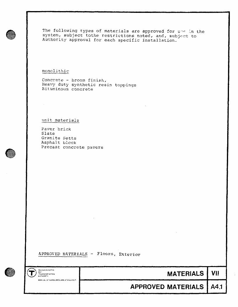
The following of materials are approved for u p the system, subject tothe ons noted, , subjf'ct to Authori instal ion.
unit
Paver brick Slate
concrete
Granite Setts Asphalt block
sh, resin
Precast concrete pavers
APPROVED MATERIALS - F' , Exterior
MATERIALS VII
APPROVED MATERIALS A4.1

•
•
•
The follwing types of materials are approved for use in the system , sUbject to the restrictions noted, and subject 0
he Director ' s approval for each specific installation .
monolithic
Concre te - smooth forms only (above vandal heigh only)
unit materials
Brick Structural glased tile Glazed ceramic tile Architectural terra co ta atural s one - smoo h aced , polished
Glazed brick Pr ocelain enamel Non- corroding metals Portland cement plaster (above vandal height only) Overlaid plywood (supervised areas only) High pressure plastic laminates (supervised areas only)
(unit materials used i n toile s mus have join s of a chemical - resistant rna erial)
surface finishes
Heavy-du y epoxy coatings Inorganic glazed coa ings Heavy- duty standard paints (above vandal ehigh only)
~A~P~P~R~O~VE~D~~T~E~R~I~A~L~S~ - Walls , Interior
(j) . c:-nn T ...... 'A'-• ....-n MATERIALS VII
APPROVED MATERIALS A4.2
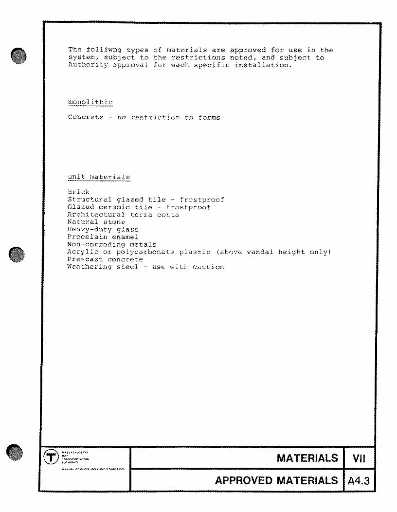
The folliwng , ect
materials are approved for use in the the restrictions noted, and subject to
Authori for each speci tallation.
Concrete - no re on
unit
azed tile - frostproof Glazed ceramic tile - frostproof Architectural terra cotta Natural stone Heavy-duty glass Procelain enamel Non-corroding metals Acrylic or polycarbonate plastic (above vandal height only) Pre-cast concrete Weathering - use with caution
MATERIALS VII
APPROVED MATERIALS A4.3

•
•
•
The following ty es of ma erials are approved for use in the system, subject to the restrictions noted, and subject to Au hority ap roy 1 for each specific installation.
monli hic
Concre e - smooth finish, unpainted preferred Portland c men plaster - smooth finish, painted Gypsum plaster - smooth finish, pain ed
uni
Prefa concrete Wood fiber panels - p in ted Panels of non-corroding metals
APPROVED ~ATERIALS - Ceiling
r.r :'::'.-u n_ \V.~
II Of'~''''
MATERIALS VII
APPROVED MATERIALS A4.4

The folliwng of materials are approved for use in the , subject to the restri ons noted, and subject to
the Director's for specif tallation.
2.
3.
4.
5.
6.
7.
8.
9.
- smooth Terrazzo
f coved to mater I (if
Troweled-on cement plaster
pa
Same material as wall or floor finish, such as brick, quar tile
steel th sa low
Concrete, stone, s rs
ted
shall be anodi one half hour minimum Stainless steel - course brushed fi
or silicone
re I stain s steel,
f shes z
where to vandals.
aluminum - all in
APPROVED MATERIALS- Miscel) anpous Materials and Finishes
MATERIALS VII
APPROVED MATERIALS A4.5
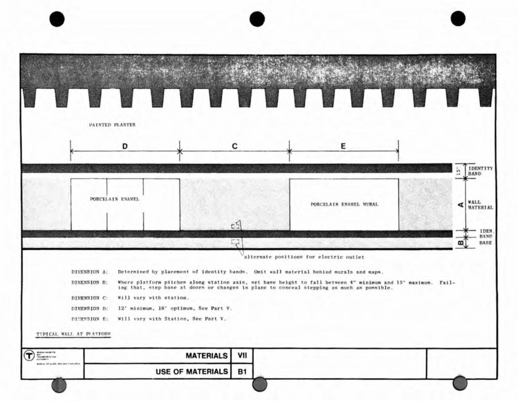
• •
l'AISTl:O PLASTER
DU'ENSJON i\ :
DI'IENS ION n.
DI~NS IO:t
DJ11F:NS ION D:
1 "r.:S tON
o c E
Rll~rnRl~ po~Jllon~ for let
()('l('rllllncd by pla .... " on t ot ldcnUt)· blind!!. OlIn ."J) lIatertal bl'hlnd "urala and.
pHch('lO along tl tllttnn ads, l'I ('t baR e hrl"ht to raIl bel ... ~('n .... lIinbuII and l ~" ... xlllu ~Iep ba~c 3t dnnrR o r change~ In plane to coo<"cal s tepping 35 auch a~ pOlOqlbJ~ .
WII) va ry with BlatJon .
12' .ln1l1uII, 16 ' optlI1U., Sec Part V.
Will vn r y -llh St a t I nn , P"rl \'.
MATERIALS I VII
USE OF MATERIALS I 81
•
F"all -
in JDFJn'lTY BA.'ID
WAl.l. cr l"ATERrA
IDEN . DA'(1)
mT DAS£
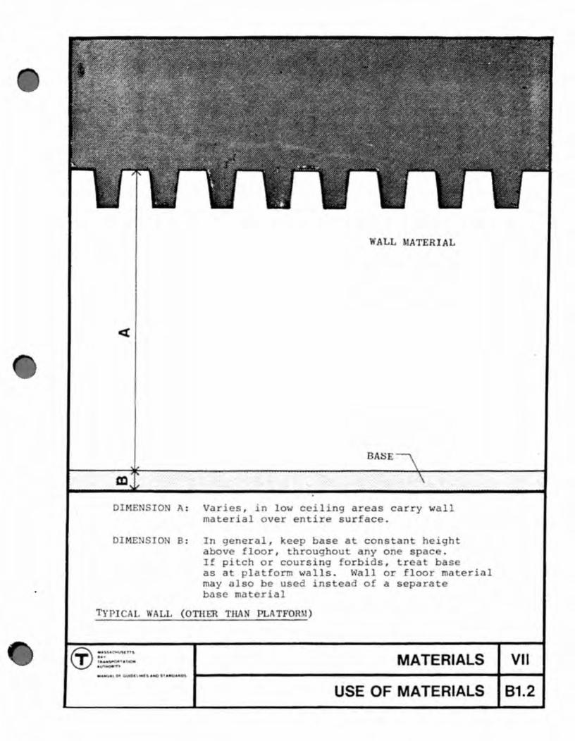
WALL 1ATERIAL
AS
DIME SIO A: Varies , in low ceiling areas carry wall material over entire surfac .
DIME SIO B: In general , keep base at cons nt heigh above floor , hroughou anyone space . If pitch or coursing forbids , rea as as a platform walls . \'1 11 or floor rna rial may also be used ins ead of a separat base rna rial
( OTH ER THA
MATERIALS VII
USE OF MATERIALS 81.2

•
•
ari
2 '- 2'
Saf y Strip . a rial H a v -du
H a y-du
Color: Sa y y 110w
lin of ta 10n nd wa 11 b yond
v coa in , sheet rubber
No e hat surfac ex ur of yel ow safe y s rip should contrac with h la orm finish to aid
he blind .
PLATFOR 1 car I1ne
MATERIALS VII Of CMIIOl t ""'I,. ,,- ..... " 1-----------------------+----1
USE OF MATERIALS 82

-
black painted
surfa~
line of station end wall beyond
Material: Heavy-duty abrasive coating Heavy-duty paint, sheet rubber
Color: Safety yellow
SAFETY STRIP AT PLATFORM kap1d Transit Lines
MATERIALS VII .,.uw." OfCUIOhiHfI4HC-J"HP"'~O' .... ----------------------t--......
USE OF MATERIALS 82.1

•
•
•
In unit masonry or til , fra'm to course .
e :l e ~
c
1-3/ 4" thick hollow met 1 door - black
~
E r--~I-Louver, if r quir d.
CI)
U)
,
0 . Q
....
Set ra m flu h with n w finish
Caulk-----------~
~D.O. ,as r q. ~ 3'6" maximum
..• "
here sheet flooring occurs carry to insid dg of frame and s ithin m tal chann 1 .
Jamb D ail
rcut, i r quir d. aximulll
R f r to Part IX or door r quir ments for each room. Ma ter keying and r quir d mak of cylinder ill be stablish d by the Dir ctor for ach tatioD.
DOORS A..~D FRAMES - Service Rooms
MATERIALS (T) "'~ I.. _nl""'''' T ...
,... f • ..,. v USE OF MATERIALS 83

In general, surfaces exposed to public contact are pres in some sort heavy-duty glazed
marking and 1 and permits It is that such exist
or in kind and that constructed similar heavy duty
materials are 1 Section
stations public contact ter or concrete. that some these st not surfacings, but simply be re-
There are so stations which final plans cannot yet be , and which will be repainted in the interim. Finally, all stations will re a amount of inting of walls, ceilings, and structure above publ contact areas. This Section C establishes guidelines for use in all three of these cases.
The lines are on four principles:
1. Major surfaces, structural members, and components should be colors -- "'"'hich are campa with the Authori standard color coded graphics.
2. Major surfaces, structural members, and components should not be cut into parts by color changes, except where absolutely necessary as at bases, or as other-
3.
wise noted fter.
Minor s should be ment should be removed,
elements, such as conduit runs, out with the surface. This
be used, however, only where they or relocated.
etc. , treatcannot
4. Visible diret-catching elements which are si-ble for cleaning should be painted dark to minimize the effects of soiling.
GENERAL PRINCIPLES
MATERIALS VII
PAINTING C1

•
•
•
All c ilings are to be painted white or ligh co or .
All walls exposed to public contact re 0 b painted with heavy dutey paint or approved synthetic coating .
1. Color chang occurs at intersection of wo planes . Doors 0 service rooms are to pain ed black .
2 . all color stops a spring line . 3 . Wall color continues between wid - spac d beams . 4. all color stops a underside of closely-spaced
beams .
MAJOR SURFACES
<IJ ::~~ _u n, ,.,.. . . .-AW' . ,. MATERIALS VII
PAINTING C2

1
2
All exposed walls on stairways are to be painted with heavy duty paint or approved synthetic coating.
1. Wall color terminates at exterior finish mat erials.
2. At very high walls above stairways, the wall color can be held down to a high wainscot running parallel to the stair slope. Wainscot height will be determined by actual conditions, but must extend above normal public contact.
MAJOR SURFACES
MATERIALS VII .... ""U ... > O' G~1\ta~ ~5. ..... I'>" • .t.f~ .fl t>.s I--------------------------t----t
PAINTING C2.1

•
1
• 2
• ••
All walls above normal public contact are to be painted a light color .
1 . At trackp ' ts the wall color is to extend down to the level of the platform . Below this line the wall, including niches, is to be dark gray .
2 . At extremely high walls, the wall color is 0 termina e a a line above normal public contact, and a ligh color used above this line . The particular station configuration will de termine the exac location of this line .
AJOR SURFACES
MATERIALS VII
PAINTING C2 .2

1 2
1. Columns are to be painted with wall color full height including capital.
2. Exception: when column is partially sheathed; the part above the sheath is to be painted another color.
3. Tie rods are to be painted wall color. 4. Members with horizontal dirt catching surfaces
within public view are to be painted wall color.
STRUCTURAL MEMBERS
MATERIALS VII
PAINTING C3

•
•
•
1. Where practicabl , existing wood benches and existing handrails may be sanded down, and refinished in he vy duty varnish.
2. All components are to be painted black. l-lhere they are exposed to public contac , the paint shall be a heavy duty type, or an approved synthetic coating.
For painting purposes, the following are to be regarded as components.
Free-standing collection booths (types presently in use, only) Turnstiles (types presently in use, only) Exit gates (types presently in use, only) Rotary Coinpassers (types presently in use, only) Fences and Guardrails Commerical facilities, not including factory finished telephone booths and lockers Advertising frames Exposed switch boxes and panel bo rd enclosures Exposed fire hose cabinets Exposed sand and salt boxes Metal stairs Bases of existing benches
COMPONENTS
MATERIALS Of ~'''''.1'.'''.
v. PAINTING C4