massachusetts institute of technology room: 3-469a department of
TRANSCRIPT
1
MASSACHUSETTS INSTITUTE OF TECHNOLOGY Room: 3-469aDEPARTMENT OF MECHANICAL ENGINEERING Tel: (617) 253-2144CAMBRIDGE, MA 02139 USA FAX: (617) 258-7881
E-mail: [email protected] 29,1999
NASA INSTITUTE FOR ADVANCED CONCEPTS
To Whom It May Concern,
Enclosed is our final report for our Phase II NIAC contract number NAS5-9801.
Organization and Department: Massachusetts Institute of TechnologyDepartment of Mechanical Engineering77 Massachusetts AvenueCambridge, MA 02139 USA
Project Title: Self-Transforming Robotic Planetary Explorers
Type of Organization: Educational
Principal Investigator: Professor Steven Dubowsky, Room 3-469aDepartment of Mechanical EngineeringMassachusetts Institute of Technology77 Massachusetts AvenueCambridge, MA 02139Tel: (617) 253-2144FAX: (617) 258-7881E-mail: [email protected]
Business Contact: Kristin Ryan, AdministratorOffice of Sponsored Programs, Room E-19-750Massachusetts Institute of Technology77 Massachusetts AvenueCambridge, MA 02139Tel: (617) 253-1696FAX: (617) 253-4734E-mail: [email protected]
Call for Proposal: NIAC 99-01 -- 1999 Phase II AdvancedAeronautical/Space Concept Study
Start Date: July 1, 1999
End Date: February 28, 2002
Steven Dubowksy, Professor

2
I. Introduction
The exploration and development of the planets and moons of the solar system in the next 10 to40 years are stated goals of NASA and the international space science community. Robots willbe required for missions to explore these bodies and in some cases build out-posts. A robot for aplanetary exploration mission may need to traverse varying terrain obstacles, climb steep clifffaces, cross wide ravines and canyons, and assemble structures. Mars terrain is rough, withenormous canyons and mountains almost three times higher than Mt. Everest. We have proposedand studied the concept of self-transforming robotic planetary explorers (STX) to meet the needsof these future missions. Detailed system simulations have been performed to evaluate thefeasibility of our concept. Prototype components have been built and experiments have beensuccessfully conducted for the proposed concepts.
A self-transforming robotic system would be able to change its configuration to overcome a widerange of physical obstacles and perform a wide range of tasks. It would enable robot scouts tolead the way, exploring, mapping and constructing facilities. A new design paradigm – binaryspace robotics has been explored to achieve such a system. It includes a 21-DOF orbital cameraarticulated mount, a 30-DOF rovers capable of camera manipulation, rock coring, robot mating(to assemble themselves into larger organisms), and a six legged 126-DOF walking robot capableof walking in rough terrain (see Figure 1). Experimental prototype binary devices and elementshave also been designed and constructed. The first generation Binary Robotic ArticulatedIntelligent Device (BRAID) is an all-plastic device, where only the wires are metal. The secondgeneration BRAID II uses integrated bi-stable latching and polymer cross-flexures. The thirdgeneration BRAID III uses Electrostrictive Polymer Artificial Muscles (EPAM) as actuators.
Figure 1: A six legged 126-DOF walking robot
The next step would be hyper-redundant binary devices with many degrees of freedomimplementing distributed flexibility to achieve large motions. Ultimately, one would like to sendbags of plastic to Mars and have them assemble themselves into robots that will achieveobjectives of the future.
II. Key Technology Developed
The self-transforming robotic system presents a number of important technical challenges, suchas in the areas of sensor technologies, communications and artificial intelligence. Our studieshave focused on the problems associated with the design of the physical system and its controlthat are relevant to the needs of NASA in the 10 to 40 year period.
3
a) System-Level Planning, Analysis and Simulation
Binary robotic systems consist of a large number of binary actuators, as opposed to a smallnumber of continuous ones, many control and planning issues are fundamentally different fromthose of conventional robotic systems. Analysis and simulation have been performed to examinethe feasibility of controlling and planning binary robotic systems in representative exploratorytasks. Appropriate planning algorithms on kinematics, trajectory following, locomotion planningand coordination have been developed. These algorithms can be imported directly into physicalimplementations without major revision. In summary, we have demonstrated that a self-transforming robotic system of a large number of binary states (103 to 104) can deliver thechanging topology necessary for truly effective planetary robots.
b) Actuator Technology and Hardware Demonstrations
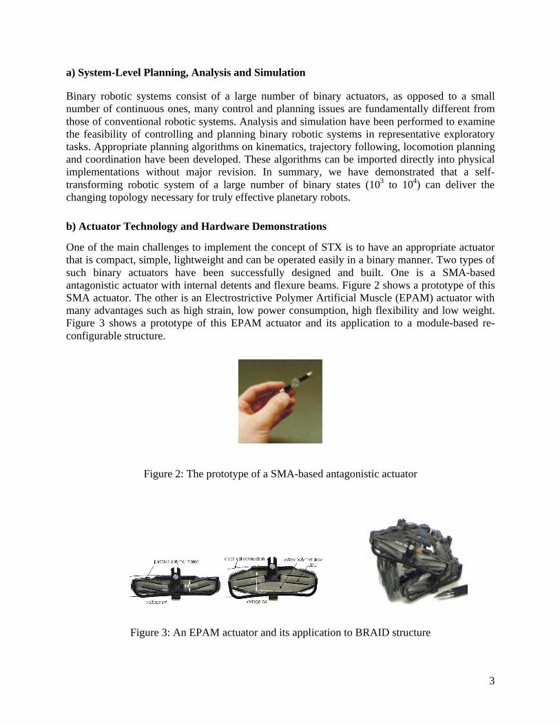
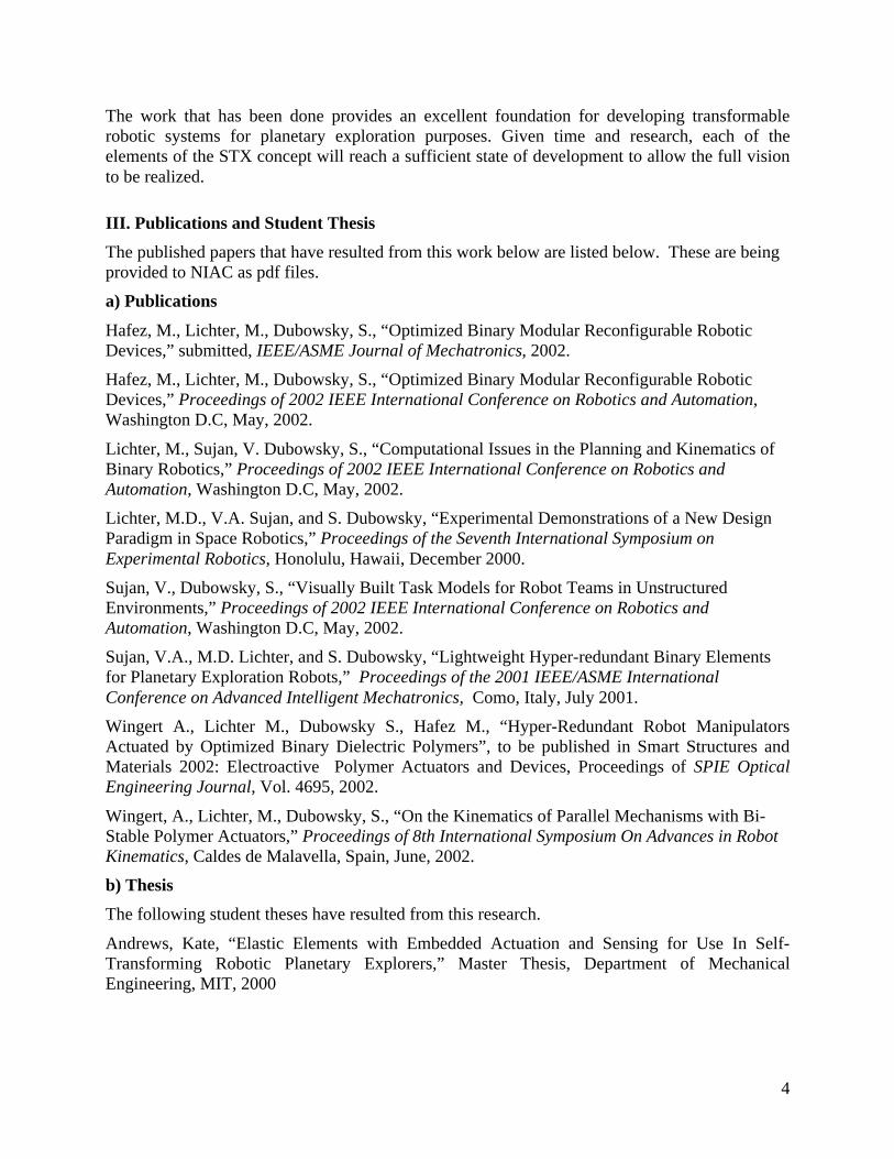
One of the main challenges to implement the concept of STX is to have an appropriate actuatorthat is compact, simple, lightweight and can be operated easily in a binary manner. Two types ofsuch binary actuators have been successfully designed and built. One is a SMA-basedantagonistic actuator with internal detents and flexure beams. Figure 2 shows a prototype of thisSMA actuator. The other is an Electrostrictive Polymer Artificial Muscle (EPAM) actuator withmany advantages such as high strain, low power consumption, high flexibility and low weight.Figure 3 shows a prototype of this EPAM actuator and its application to a module-based re-configurable structure.
Figure 2: The prototype of a SMA-based antagonistic actuator
Figure 3: An EPAM actuator and its application to BRAID structure
4
The work that has been done provides an excellent foundation for developing transformablerobotic systems for planetary exploration purposes. Given time and research, each of theelements of the STX concept will reach a sufficient state of development to allow the full visionto be realized.
III. Publications and Student Thesis
The published papers that have resulted from this work below are listed below. These are beingprovided to NIAC as pdf files.
a) Publications
Hafez, M., Lichter, M., Dubowsky, S., “Optimized Binary Modular Reconfigurable RoboticDevices,” submitted, IEEE/ASME Journal of Mechatronics, 2002.
Hafez, M., Lichter, M., Dubowsky, S., “Optimized Binary Modular Reconfigurable RoboticDevices,” Proceedings of 2002 IEEE International Conference on Robotics and Automation,Washington D.C, May, 2002.
Lichter, M., Sujan, V. Dubowsky, S., “Computational Issues in the Planning and Kinematics ofBinary Robotics,” Proceedings of 2002 IEEE International Conference on Robotics andAutomation, Washington D.C, May, 2002.
Lichter, M.D., V.A. Sujan, and S. Dubowsky, “Experimental Demonstrations of a New DesignParadigm in Space Robotics,” Proceedings of the Seventh International Symposium onExperimental Robotics, Honolulu, Hawaii, December 2000.
Sujan, V., Dubowsky, S., “Visually Built Task Models for Robot Teams in UnstructuredEnvironments,” Proceedings of 2002 IEEE International Conference on Robotics andAutomation, Washington D.C, May, 2002.
Sujan, V.A., M.D. Lichter, and S. Dubowsky, “Lightweight Hyper-redundant Binary Elementsfor Planetary Exploration Robots,” Proceedings of the 2001 IEEE/ASME InternationalConference on Advanced Intelligent Mechatronics, Como, Italy, July 2001.
Wingert A., Lichter M., Dubowsky S., Hafez M., “Hyper-Redundant Robot ManipulatorsActuated by Optimized Binary Dielectric Polymers”, to be published in Smart Structures andMaterials 2002: Electroactive Polymer Actuators and Devices, Proceedings of SPIE OpticalEngineering Journal, Vol. 4695, 2002.
Wingert, A., Lichter, M., Dubowsky, S., “On the Kinematics of Parallel Mechanisms with Bi-Stable Polymer Actuators,” Proceedings of 8th International Symposium On Advances in RobotKinematics, Caldes de Malavella, Spain, June, 2002.
b) Thesis
The following student theses have resulted from this research.
Andrews, Kate, “Elastic Elements with Embedded Actuation and Sensing for Use In Self-Transforming Robotic Planetary Explorers,” Master Thesis, Department of MechanicalEngineering, MIT, 2000

5
Fontaine, Ebraheem, “A Laboratory Demonstration of a Parallel Robotic Mechanism withIntegrated EPAM Actuators,” Bachelor Thesis, Department of Mechanical Engineering, MIT,2002.
Lichter, Matt, “Concept Development for Lightweight Binary-Actuated Robotic Devices, withApplication to Space Systems,” Master Thesis, Department of Mechanical Engineering, MIT,2001
Oropeza, Guillermo, “The Design of Lightweight Deployable Structures for SpaceApplications,” Bachelor Thesis, Department of Mechanical Engineering, MIT, 1999.
Rapp, Lani, “Design of a Mechanism to Amplify the Motion of Shape Memory Alloys,”Bachelor Thesis, Department of Mechanical Engineering, MIT, 2001
Weiss, Peter, “Development and Optimization of Electrostrictive Polymer Artificial MusclesActuators with Large Expansions and High Forces,” Diplome D'Ingenieurs, Ecole PolytechniqueFemenine (EPF), Paris, France, 2001.
Wingert, Andreas, “Development of a Polymer-Actuated Binary Manipulators,” Master Thesis,Department of Mechanical Engineering, MIT, 2002.
Optimized Binary Modular Reconfigurable Robotic Devices
Moustapha Hafez Matthew D. Lichter Steven Dubowsky Department of Mechanical Engineering, Massachusetts Institute of Technology
Cambridge, MA 02139 USA, Email: hafez/lichter/[email protected]
Abstract
Binary robotic devices with large numbers of degrees of freedom have been proposed by a number of researchers. However, experimental implementations of these concepts have been built with conventional components. These physical systems are heavy, complex, and far from being practical devices. In this paper, a lightweight, compliant mechanism driven by optimized magnet-coil actuators is proposed and developed as an element for modular hyper-redundant robotic systems. Such elements could be used in a number of applications and would replace conventional, complex, and heavy components. The device has a parallel kinematics structure. Its binary actuation simplifies its control architecture. Analytical and experimental results for a practical prototype system are presented. 1. Introduction
Challenging applications are being proposed for robotic systems such as robots for surgery, service in the home, and space exploration [1]. Researchers have proposed robotic systems based on binary movements [2-5]. These devices, which can be called digital mechanisms, are able to perform precise, discrete motions without need for sensing, complex electronics, or feedback control. Traditional mechanisms have a small number of continuous degrees of freedom (DOF). A digital mechanism approximates this motion by using a large number of binary DOF. The larger the number of DOF, the smaller the position and orientation error [6,7]. Recent studies have considered the kinematic motion of these devices in more depth [8]. However, most experimental implementations of the concept have been done with conventional components using elements such as bearings and gears. Since a large number of DOF are required, they are heavy, expensive and not practical. Therefore, new design paradigms are required for such systems. An optimized binary modular reconfigurable device is proposed in this paper. It has potential applications in the biomedical field such as camera or light positioning for surgeon assistance. Moreover, such elements could be used as key components for self-transforming robots for planetary exploration [6,7,9,10]. The overall design is based on the assembly of modular parallel platforms. This allows the device to reconfigure itself to achieve
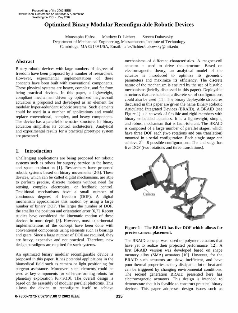
mechanisms of different characteristics. A magnet-coil actuator is used to drive the structure. Based on electromagnetic theory, an analytical model of the actuator is introduced to optimize its geometric parameters and maximize its efficiency. The discrete nature of the mechanism is ensured by the use of bistable mechanisms (briefly discussed in this paper). Deployable structures that are stable at a discrete set of configurations could also be used [11]. The binary deployable structures discussed in this paper are given the name Binary Robotic Articulated Integrated Devices (BRAID). A BRAID (see Figure 1) is a network of flexible and rigid members with binary embedded actuators. It is a lightweight, simple, and robust mechanism that is fault-tolerant. The BRAID is composed of a large number of parallel stages, which have three DOF each (two rotations and one translation) mounted in a serial configuration. Each single stage can achieve 23 = 8 possible configurations. The end stage has five DOF (two rotations and three translations).
Figure 1 – The BRAID has five DOF which allows for precise camera placement.
The BRAID concept was based on polymer actuators that have yet to realize their projected performance [12]. A first BRAID version was developed based on shape memory alloy (SMA) actuators [10]. However, for the BRAID such actuators are slow, inefficient, and have poor thermal properties as they dissipate a lot of heat and can be triggered by changing environmental conditions. The second generation BRAID presented here has electromagnetic actuators. This design is intended to demonstrate that it is feasible to construct practical binary devices. This paper addresses design issues such as
335

flexure design and bistable mechanisms and discusses the detailed actuator modeling and optimization. Simulations [7] and experimental results suggest that practical binary devices with large number of DOF can be achieved with current technology. 2. BRAID design
BRAID structures are made largely of polymer materials (plastics) to make them lightweight. Figure 2 shows an exploded view of a single stage. The three legs each have two one-DOF flexural bearings, which can rotate by ± 25° and ± 17° respectively. This eliminates the need for heavy conventional bearings with their friction, backlash, and added weight. The system also decreases the demands on the actuators. One cone-ball sliding bearing with three rotational DOF is used for each leg. This sliding bearing satisfies the large angles of tilt up to ± 60°, while keeping a high structural stiffness. This is difficult to achieve with flexural bearings. The stages are mounted on each other using magnetic preload forces between permanent magnets and steel parts. This magnetic connection enables a modular design, which is of prime importance for reconfigurability. The structure is driven by electromagnetic actuators composed of curved magnets and coils to minimize the air gap between the actuator components. Finally, bistable mechanisms are integrated in the design to enforce the binary discrete motion. These also eliminate the need to power the device to hold it in position.
Figure 2 - Exploded view of a single stage.
The material selected for the BRAID structure, which incorporates both flexural and sliding bearings, is Delrin® 100 (PolyOxyMethylene with 20% Teflon). Delrin® has high tensile strength, impact resistance, stiffness, and fatigue endurance. These properties make it a good choice for flexural hinges. Delrin® has excellent wear and friction behavior due to its natural lubricity. Such
properties lead to highly efficient sliding bearings. Delrin® is also easily machinable using water-jet cutting technology and traditional machining processes. The key elements of the BRAID, which are discussed in detail below, are its bearings, actuators, and bistable mechanisms. 2.1 Design of compliant bearings
Flexural bearings are wear-free and their motions are smooth and continuous. The accuracy of a flexural bearing depends on how well the bearing is assembled and machined. They have high repeatability and resolution. However, they have some disadvantages. The stiffness of such bearings is inversely proportional to the range of motion. They are sensitive to thermal variations especially when made from polymers. They cannot tolerate large loads and are susceptible to buckling. Finally, a flexible connection might result in vibration problems in some high-speed applications. The flexible pivot configuration chosen for the BRAID is based on cross-flexural hinges (see Figure 3a). It consists of a pair of crossed plastic leaf springs of uniform length (l), width (b), and thickness (h). Compared to other types of flexural bearings, cross-flexural hinges greatly improve fatigue life, range of motion, and out-of-plane stiffness.
(a) cross-flexural hinge (b) BRAID stage
Figure 3 – Flexural bearings.
Angular stiffness
For small angular deflections of the bearing (α), it is convenient to assume that the springs deform in a circular arc shape. In this case the angular stiffness (Kα) of the cross-springs is twice the stiffness of a single leaf spring in pure rotation.
2EIK
lα = where 3
12
bhI = (1)
(I) is the moment of inertia, and (E) the Young’s modulus of elasticity. For larger angular deflections such as required for the BRAID (α = ± 25°), the strip does not deform exactly in a circular arc and its stiffness is higher. For such angular deflections, stiffness increases by less than 10% [13,14].
336

Angular deflection limits
If the springs are assumed to deform in the shape of a circular arc, then the allowed deflection (αall) of the cross-spring hinge is equal to the deflection of a single leaf spring and is given by:
Eh
lallall
σα 2= (2)
For larger angles, the allowable stresses in the springs (σall) increase due to a non-circular arc deformation. For an angular deflection of 45˚, the stress is 30% greater for the same deflections given by equation (2) [14]. The Delrin® has a 107 cycles fatigue stress (σall) of 30 MPa and its Young’s modulus is 2600 MPa [15]. Using these values and a safety factor, the leaf springs in the BRAID (see Figure 3b) have the following dimensions of l1 = 10.7 mm (0.424”), l2 = 7.2 mm (0.283”), b = 3.175 mm (0.125”), and h = 0.51 mm (0.02”) to achieve 107 cycles of ± 25° and ± 17° for l1 and l2 respectively. A life of 107 cycles is quite adequate for most robotic applications. 2.2 BRAID Sliding bearing design
Because sliding contact bearings often distribute loads over a large area, contact stresses and space requirements are often low while stiffness and damping are usually high. A spherical bearing, which is composed of a ball that slides in a cone, is appropriate for the kinematics of the BRAID structure as it provides three rotational DOF. The materials for this bearing were selected to give minimum wear and friction. Polymers in contact with a hard material with very low surface roughness meet this objective. The result is low adhesive interaction at the contact points, which leads to low friction, minimal stick- slip effect, and relatively low wear. A cone made of Delrin® and a ruby ball appears to be almost an ideal combination [17]. However to preload the joint by using a magnet beneath the cone, a corrosion resistant magnetic steel ball is used. This bearing has a life that approaches 107 cycles. In order to ensure an accurate tilt, almost no wear is allowed on the ball and just slight wear on the cone. Comprehensive wear and friction analyses for this type of sliding bearing have been done previously [16,17]. 3. Electromagnetic actuator design
Electromagnetic actuators (also called voice coils) are frequently used in high performance and high precision applications such as disk drive head positioning. They were selected for the BRAID because the main actuator design criteria are the deliverable force, the power
dissipation, and the total volume and mass of the actuator. The choice of magnet and coil geometry with a rectangular cross-section was made mainly on the available space in the BRAID structure and on the manufacturing technologies offered. Closed-form expressions have been derived for the levitation forces between two circular magnetic discs and two non-coaxial circular coils [18,19]. While an optimized circular magnet-coil force actuator and its application to precision elastic mechanisms has been presented [20], almost no literature is available for coils with rectangular cross-sections. Based on the laws of magnetostatics and the
magnetic vector potential ( A!
), an analytical model was developed in this study to determine the force between the curved magnets and coils with a rectangular cross-section and is briefly presented below. An analytical model of a magnet-coil actuator with rectangular cross-section
The X-component of the magnetic vector potential (Ax) in a wire segment of length (L1) (see Figure 4a) going in the X-direction, with its middle point at the origin and in which is flowing a current (I1) is given by [21]:
1
1
/ 2
112 2 2
/ 2 14 ( )
L
ox
L
IA dx
x x y z
µπ−
= ⋅− + +∫ (3)
The magnetic field ( B!
) created by this current is derived
from B A curlA= ∇ × =! !! !
. In the case of a straight wire positioned along the X-axis, the X-component of the magnetic field ( B
!) is zero and the two other components
are given in the following equations:
0xB = , xy
AB
z
∂=
∂, x
z
AB
y
∂= −
∂ (4)
For two wire parallel segments (see Figure 4a), one of length (L1) and with a current (I1) and the other wire of length (L2) with a current (I2), there is an attractive or repelling force between them. The direction of the force depends on the currents’ directions. An attractive force is created if the two currents flow in the same direction. The Y and Z components of the force acting on wire 2 due to the current flowing in wire 1 can be determined from the general equation of Lorentz force:
F Idl B= ×∫! ! !" (5)
where ( dl!
) is an element along the length of the conductor. The (Fy) and (Fz) are expressed as follows:
337

2
2
/ 2
2
/ 2
L
y y
L
F I B dx−
= ⋅∫ and 2
2
/ 2
2
/ 2
L
z z
L
F I B dx−
= ⋅∫ (6)
L
I
X
Y
Z
(0,0,0)
LI
1
1
2
2
Magnetization
(a) Parallel wire segments (b) Actuator model
Figure 4 – Electromagnetic actuator. These formulas can be applied to calculate the resulting force between a magnet and a coil. In fact, it is possible to represent a permanent magnet by a coil, which has one single layer of a conducting material with a certain number of turns. The curved axis of the coil corresponds to the magnetization direction of the permanent magnet. Therefore, the following relation applies:
rmag
o
BN I h
µ⋅ = ⋅ (7)
where (N) is the number of turns, (I) the current flowing in the coil, (Br) the remanence of the magnet, and (hmag) is the height along magnetization. This equation is valid in the case where the BH-curve is a straight line in the second quadrant. On the other hand, when the material has a non-linear behavior, the right hand side term of equation (7) should be divided by the relative recoil permeability (µr). The actuator can be represented by an equivalent analytical model (see Figure 4b). The two components of the force between each single wire and all the other parallel wires in both the x and y directions are calculated from equations (6). In the case of full symmetry, which means that the two coils are coaxial, the forces acting in the y direction between two parallel wires cancel. The sum of forces along the z-axis (Fact) gives the force generated by the actuator.
act zF F= ∑ (8)
Because of the BRAID binary action, actuators are not judged on linearity, accuracy, or resolution but on the force delivered. Figure 5 shows a plot of the calculated force delivered by the linear actuator as a function of the distance between the center of gravity of both the magnet and the coil (D). The Nd-Fe-B magnet dimension is 10 x 6 x 6 mm3 and the coil is 15 x 15 x 14 mm3 with a
thickness of 4.2 mm. The number of turns (N) is 250, and a peak current of 3A is used.
Figure 5 - The calculated magnetic force. The position of the magnet with respect to the coil is very important as the force varies significantly from one position to another. It should be noted that when the two centers of gravity coincide (D = 0), the force delivered by the actuator is zero. The force increases to a maximum value when the magnet is partially in and partially out (positions A and B). The force then decreases exponentially as the two components move apart. In the BRAID actuators act in parallel with bistable mechanisms that hold the structure in either of the two desired positions even when the power is off. Power to the actuators is only required to move from one state to another. Using low-duty-cycle impulses in the millisecond range as input signals to the actuator allows the use of peak currents that are relatively high (several amperes) while keeping power dissipation in the coil at an admissible level.
(a) Side view (b) Single Braid stage Figure 6 - Prototype with a limited angle of rotation.
If just one side of the coil is used (see Figure 6), it is quite difficult to get an efficient binary actuator although it is possible to achieve moderate deflections. The two binary states will lie on each side of the peak shown in Figure 5 as the two points indicated C and C’. A more efficient actuation method is to use both ends of the coil where the
338
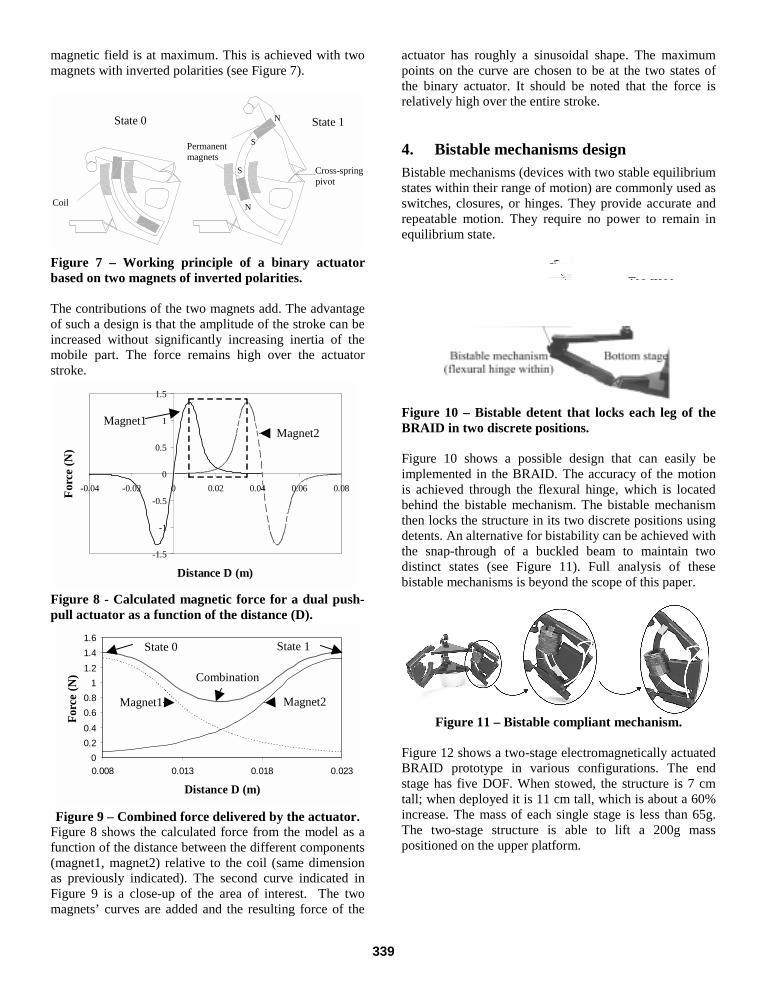
magnetic field is at maximum. This is achieved with two magnets with inverted polarities (see Figure 7).
State 0 State 1
Cross-spring pivot
Permanent magnets
Coil
N
N
S
S
Figure 7 – Working principle of a binary actuator based on two magnets of inverted polarities. The contributions of the two magnets add. The advantage of such a design is that the amplitude of the stroke can be increased without significantly increasing inertia of the mobile part. The force remains high over the actuator stroke.
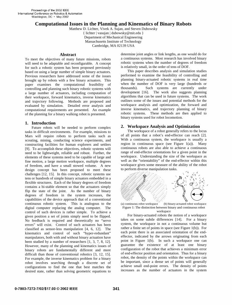
Figure 8 - Calculated magnetic force for a dual push-pull actuator as a function of the distance (D).
Figure 9 – Combined force delivered by the actuator.
Figure 8 shows the calculated force from the model as a function of the distance between the different components (magnet1, magnet2) relative to the coil (same dimension as previously indicated). The second curve indicated in Figure 9 is a close-up of the area of interest. The two magnets’ curves are added and the resulting force of the
actuator has roughly a sinusoidal shape. The maximum points on the curve are chosen to be at the two states of the binary actuator. It should be noted that the force is relatively high over the entire stroke. 4. Bistable mechanisms design
Bistable mechanisms (devices with two stable equilibrium states within their range of motion) are commonly used as switches, closures, or hinges. They provide accurate and repeatable motion. They require no power to remain in equilibrium state.
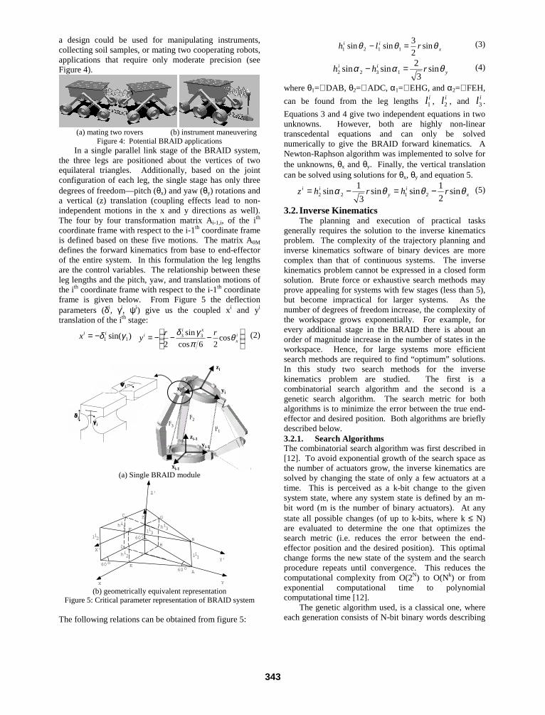
Figure 10 – Bistable detent that locks each leg of the BRAID in two discrete positions. Figure 10 shows a possible design that can easily be implemented in the BRAID. The accuracy of the motion is achieved through the flexural hinge, which is located behind the bistable mechanism. The bistable mechanism then locks the structure in its two discrete positions using detents. An alternative for bistability can be achieved with the snap-through of a buckled beam to maintain two distinct states (see Figure 11). Full analysis of these bistable mechanisms is beyond the scope of this paper.
Figure 11 – Bistable compliant mechanism.
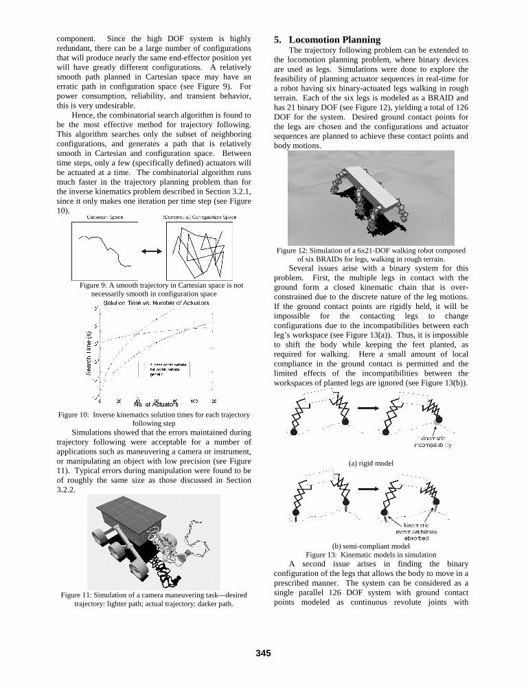
Figure 12 shows a two-stage electromagnetically actuated BRAID prototype in various configurations. The end stage has five DOF. When stowed, the structure is 7 cm tall; when deployed it is 11 cm tall, which is about a 60% increase. The mass of each single stage is less than 65g. The two-stage structure is able to lift a 200g mass positioned on the upper platform.
-1.5
-1
-0.5
0
0.5
1
1.5
-0.04 -0.02 0 0.02 0.04 0.06 0.08
Distance D (m)
For
ce (
N)
Magnet1 Magnet2
00.20.40.60.8
11.21.41.6
0.008 0.013 0.018 0.023
Distance D (m)
For
ce (
N)
State 0 State 1
Magnet1 Magnet2
Combination
339

Figure 12 - Two-stage electromagnetically actuated BRAID prototype in various configurations. 5. Conclusion and perspectives
The Binary Robotic Articulated Integrated Device (BRAID) presented in this paper is a concept module for robotic systems that are capable of accomplishing tasks of substantial complexity, with flexibility and robustness. The electromagnetic actuator proposed provides considerable force to drive the structure and provides large deflections that lead to a large workspace of the manipulator. The bistable mechanisms introduced in this paper lock the structure into discrete states to conserve power and provide high accuracy and repeatability. For a more efficient design that allows a larger number of stages, each module will be designed according to the mass it is required to displace. Thus the stage located at the base will be larger than the end stage used for tool manipulation, since it will require larger and more powerful actuators. The BRAID silhouette will have a conical shape rather than a cylindrical shape, which will also increase the resolution of the manipulator. Currently applications for BRAID devices are being studied which include assistance devices for operating rooms and camera positioning mechanisms for mobile robots. Acknowledgements
The authors acknowledge the NASA Institute for Advanced Concepts (NIAC) for supporting this research. Also, the important contributions of Ebraheem Fontaine, Vivek Sujan, and Andreas Wingert in the fabrication and design analysis are acknowledged. References
[1] Huntsberger, T.L., Rodriguez G., and Schenker P.S. “Robotics: Challenges for Robotic and Human Mars Exploration” Proceedings of ROBOTICS2000, Albuquerque, NM, Mars 2000.
[2] Anderson V.C., and Horn R.C., “Tensor Arm Manipulator Design” ASME paper, 67-DE-57, 1967.
[3] Roth B., Rastegar J., Scheinman V., “On the Design of Computer Controlled Manipulators” First CISM-IFTMM Symposium on Theory and Practice of Robots and Manipulators, pp 93-113, 1973.
[4] Chirikjian, G.S. “A Binary Paradigm for Robotic Manipulators” Proc. IEEE International Conference on
Robotics and Automation, pp. 3063-3069, San Diego, California, USA. May 8-13, 1994.
[5] Chirikjian, G.S. and Ebert-Uphoff, I. “Discretely Actuated Manipulator Workspace Generation Using Numerical Convolution on the Euclidean Group” Proceedings of the 1998 IEEE, International Conference on Robotics and Automation, Leuven, Belgium. May 16-21 1998.
[6] Lichter, M.D. Sujan, V.A., and Dubowsky, S., “Computational Issues in The Planning and Kinematics of Binary Robots”. Proceedings of the 2002 IEEE International Conference on Robotics and Automation, Washington D.C. May 2002.
[7] Lichter, M.D., “Concept Development for Lightweight Binary-Actuated Robotic Devices, with Application to Space Systems” Master’s thesis. The Massachusetts Institute of Technology, Cambridge, USA, 2001.
[8] Hamlin G.J., and Sanderson A.C. “TETROBOT: A Modular Approach to Reconfigurable Parallel Robotics”. Kluwer Academic Publishers, 1998.
[9] Lichter, M.D., Sujan, V.A., and Dubowsky, S. “Experimental Demonstrations for a New Paradigm in Space Robotics”. Proceedings of the Seventh International Symposium on Experimental Robotics, ISER ‘00. Hawaii, pp. 225-234. December 10, 2000.
[10] Sujan, V.A., Lichter, M.D., and Dubowsky, S. “Lightweight Hyper-redundant Binary Elements for Planetary Exploration Robots”. Proc. 2001 IEEE/ASME International Conference on Advanced Intelligent Mechatronics (AIM '01) 811 July 2001, Como, Italy.
[11] Kumar, P. and Pellegrino, S., “Kinematic Bifurcations in the Simulation of Deployable Structures” IASS-IACM, ISASR, Athens, Greece 2000.
[12] Madden, J.D., Cush, R.A., Kanigan, T.S., Hunter, I.W. “Fast Contracting Polypyrrole Actuators”. Synthetic Metals, Vol. 113 (2000) pp. 185-192.
[13] Wittrick, W. H., “The Properties of Crossed Flexure Pivots, and the Influence of the Point at Which The Strips Cross”. The Aeronautical Quarterly II (4), pp 272-292, 1951.
[14] Haringx, J. A.“The Cross-Spring Pivot as a Constructional Element”, Applied Science Research, pp 313-332, 1949.
[15] http://plastics.dupont.com/ [16] Hafez, M., Sidler T., Salathe R., Jansen G. and Compter J.
“Design, Simulations and Experimental Investigations of a Tip/Tilt Scanner” Mechatronics, 10, 2000 pp. 741-760.
[17] Hafez, M., “Compact Fast-Steering Tip/Tilt Laser Scanner for High-Power Material Processing Applications” PhD Thesis, The Swiss Federal Institute of Technology, Lausanne, Switzerland, 2000.
[18] Furlani E. P., “Formula for The Levitation Force Between Magnetic Disks” IEEE Transactions on Magnetics, Vol. 29, No. 6. November 1993.
[19] Kim K. , Levi E., Zabar, Z. and Birenbaum, L., “Restoring Force Between Two Noncoaxial Circular Coils” IEEE Transactions on Magnetics, Vol. 32, No. 2, March 1996.
[20] Smith S.T., Chetwynd D.G., “An optimized Magnet Coil Force Actuator and its Application to Precision Elastic Mechanisms” Proceedings of the Institution of Mechanical Engineers. Vol. 204, pp.243-253, 1990.
[21] Compter J. C., “Snelle Aandrijvingen Met Korte Slag – Fast Actuators With Short Strokes” PhD Thesis Technical University of Delft, The Netherlands, 1976.
340
Computational Issues in the Planning and Kinematics of Binary RobotsMatthew D. Lichter, Vivek A. Sujan, and Steven Dubowsky
{ lichter | vasujan | [email protected] }Department of Mechanical EngineeringMassachusetts Institute of Technology
Cambridge, MA 02139 USA
AbstractTo meet the objectives of many future missions, robotswill need to be adaptable and reconfigurable. A conceptfor such a robotic system has been proposed previouslybased on using a large number of simple binary actuators.Previous researchers have addressed some of the issuesbrought up by robots with a few binary actuators. Thispaper examines the computational feasibility ofcontrolling and planning such binary robotic systems witha large number of actuators, including computation oftheir workspace, forward kinematics, inverse kinematicsand trajectory following. Methods are proposed andevaluated by simulation. Detailed error analysis andcomputational requirements are presented. An exampleof the planning for a binary walking robot is presented.
1. IntroductionFuture robots will be needed to perform complex
tasks in difficult environments. For example, missions toMars will require robots to perform tasks such asscouting, mining, conducting science experiments, andconstructing facilities for human explorers and settlers[9]. To accomplish these objectives, robotic systems willneed to be lightweight, reliable and robust. Further, theelements of these systems need to be capable of large andfine motion, a large motion workspace, multiple degreesof freedom, and have a small stowed volume. A newdesign concept has been proposed to meet thesechallenges [12, 15]. In this concept, robotic systems usetens or hundreds of simple binary actuators embedded in aflexible structures. Each of the binary degrees of freedomcontains a bi-stable element so that the actuators simplyflip the state of the joint. As the number of binarydegrees of freedom in the system increases, thecapabilities of the device approach that of a conventionalcontinuous robotic system. This is analogous to thedigital computer replacing the analog computer. Thecontrol of such devices is rather simple. To achieve agiven position a set of joints simply need to be flipped.No feedback is required and theoretically no “servoerrors” will exist. Control of such actuators has beenclassified as sensor-less manipulation [4, 6, 12]. Thekinematics and control of such “hyper-redundant”manipulators, both with and without binary actuation havebeen studied by a number of researchers [1, 3, 7, 8, 12].However, many of the planning and kinematics issues ofbinary robots are fundamentally different and moredifficult than those of conventional robotics [3, 12, 15].For example, the inverse kinematics problem for a binaryrobot involves searching through a discrete set ofconfigurations to find the one that best matches thedesired state, rather than solving geometric equations to
determine joint angles or link lengths, as one would do fora continuous systems. Most research has involved binaryrobotic systems when the number of degrees of freedomis relatively small, in the order of tens of DOF.
This paper describes analysis and simulation studiesperformed to examine the feasibility of controlling andplanning binary-actuated robotic systems in real timewhen the number of DOF is very large (hundreds orthousands). Such systems are currently underdevelopment [16]. The work also suggests planningalgorithms that can be used in future systems. The workoutlines some of the issues and potential methods for theworkspace analysis and optimization, the forward andinverse kinematics, and trajectory planning of binaryrobotic systems. These methods are then applied tobinary systems used for robot locomotion.
2. Workspace Analysis and OptimizationThe workspace of a robot generally refers to the locus
of all points that a robot’s end-effector can reach [2].With a continuous system, the workspace is usually aregion in continuous space (see Figure 1(a)). Manycontinuous robots are also able to achieve a continuousrange of end-effector orientations for a given point in theworkspace. Understanding the size of the workspace aswell as the “orientability” of the end-effector within thisworkspace gives some measure of the ability of the robotto perform diverse manipulation tasks.
(a) continuous robot workspace (b) binary-actuated robot workspaceFigure 1: The distinction between binary and continuous robot
workspaceFor binary-actuated robots the notion of a workspace
takes on some subtle differences [14]. For a binarysystem, the workspace in not a continuous volume butrather a finite set of points in space (see Figure 1(b)). Foreach point there is an associated orientation of the end-effector, indicated by the arrows originating from eachpoint in Figure 1(b). In such a workspace one canguarantee the existence of at least one binaryconfiguration of the robot that achieves a minimum errorof end-effector position and orientation. Thus for a binaryrobot, the density of the points within the workspace canbe important, since a dense set of points will generallyachieve small end-point errors. The density of pointsincreases as the number of actuators in the system
341

increases. Each additional actuator doubles the number ofworkspace points.
It is useful to view a discrete workspace cloud fromthe perspective of a density function map. In designing abinary robot, one might want to optimize its workspace.For example, it may be desirable for repeated pick andplace tasks to have a workspace that has a great density ofpoints in the pick and place locations. In other cases, itmight be desirable to have a uniform distribution ofreachable points over the entire workspace. To deal withsuch issues the notion of workspace distribution isproposed. For a planar robot, a density map representsthe density of points (the z-axis) versus the Cartesianlocation in space (the x- and y-axes). With a discretecloud, the density map appears as delta functions at eachworkspace point, with all other areas of the map having avalue of zero density (see Figure 2 (a)). Applying a low-pass filter (such as convolution with a Gaussian function)to the density map, the spikes blend together and providea continuous approximation of the density of theworkspace (see Figure 2(b)).
(a) discrete point cloud
(b) continuous representation
(c) optimized uniform workspace densityFigure 2: Workspace of a 6 DOF serial binary manipulator with
optimizationThis continuous approximation can be a metric for
the uniformity/distribution of the workspace. Here it isdefined based on the standard deviation of the workspacedensity. A small standard deviation of the workspacedensity indicates a more uniform distribution. Thismethod for quantifying the distribution of the workspacecan be extended to three-dimensional workspaces andinclude endpoint orientation information.
As an example of optimizing a binary robot design toprovide uniform workspace density, consider a serialplanar manipulator, having between four and ten binary
actuators. The lengths of each link, li, and the angles ofdeviation of each binary rotary joint, ϕI are to beoptimized. This robotic design results in a planarworkspace composed of 2N points, where N is the numberof binary actuators.
Using an evolutionary algorithm the design variablesof this system can be optimized. The algorithm generatesa random set of candidate designs and evaluated thembased on their uniformity of workspace. The bestcandidates (those with the most uniform workspacedensities) are evolved in the classical manner withmutation. A few hundred generations result in goodsolutions to the problem. An example of one suchoptimization (for an un-optimized system shown in figure2(a)) is shown in Figure 2(c). Note that the density mapin this figure is much more uniform than the one shown inFigure 2(b).
3. Kinematics3.1. Forward Kinematics
For binary robotic systems, it is convenient toformulate the forward kinematics using four-by-fourhomogeneous transformation matrices [2]. For example,the transformation matrix A0,M describing the position andorientation of the end-effector relative to the base can beviewed as the product of the M intermediatetransformations Ai-1,i from module to module within thestructure:
∏=
−− =⋅⋅⋅=M
iiiMMM AAAAA
1,1,12,11,0,0 ! (1)
where M is the number of intermediate modulescomprising the binary robotic system [15].
Due to the discrete nature of binary devices, eachterm of the intermediate transformation Ai-1,i can haveonly a finite number of possible values. If each modulehas only a few binary degrees of freedom, all the valuesthat the terms of Ai-1,i can be easily enumerated. Forexample, if a module has three binary DOF, then themodule has 23 or 8 possible values for Ai-1,i (notated by Ai-
1,i(1), Ai-1,i
(2), …, Ai-1,i(8)). The solution of the module
kinematics may require trigonometric or more complexmathematics, but these need only be solved once, andpossibly offline. This reduces online computationalloads.
Figure 3: BRAID—a serial chain of binary-actuated parallelstages
An example of such a robot is the Binary RoboticArticulated Intelligent Device (BRAID), developed at theField and Space Robotics Laboratory, which is a serialstack of identical parallel stages [15] (see Figure 3). Such
…
342
a design could be used for manipulating instruments,collecting soil samples, or mating two cooperating robots,applications that require only moderate precision (seeFigure 4).
(a) mating two rovers (b) instrument maneuvering
Figure 4: Potential BRAID applicationsIn a single parallel link stage of the BRAID system,
the three legs are positioned about the vertices of twoequilateral triangles. Additionally, based on the jointconfiguration of each leg, the single stage has only threedegrees of freedom—pitch (θx) and yaw (θy) rotations anda vertical (z) translation (coupling effects lead to non-independent motions in the x and y directions as well).The four by four transformation matrix Ai-1,i, of the ith
coordinate frame with respect to the i-1th coordinate frameis defined based on these five motions. The matrix A0M
defines the forward kinematics from base to end-effectorof the entire system. In this formulation the leg lengthsare the control variables. The relationship between theseleg lengths and the pitch, yaw, and translation motions ofthe ith coordinate frame with respect to the i-1th coordinateframe is given below. From Figure 5 the deflectionparameters (δi, γi, ψi) give us the coupled xi and yi
translation of the ith stage:
)sin( 11 γδ iix −=
−−−= i
x
xii rr
y θπ
γδcos
26cos
sin
233 (2)
Flexure to allow lateral motion of the links
xi-1
yi-1
zi-1
zi
xi
li1
li2li3
yi
δδδδij
γγγγij
ψψψψij
(a) Single BRAID module
X Y
Z
Z'
X'
Y'
A
B
C
D
E
F
G
H
60o
60o
60o
li1
li3li2
hi1
hi2
hi3
(b) geometrically equivalent representationFigure 5: Critical parameter representation of BRAID system
The following relations can be obtained from figure 5:
xii rlh θθθ sin
2
3sinsin 1121 =− (3)
yii rhh θαα sin
3
2sinsin 1322 =− (4)
where θ1=∠ DAB, θ2=∠ ADC, α1=∠ EHG, and α2=∠ FEH,
can be found from the leg lengths il1 , il2 , and il3 .
Equations 3 and 4 give two independent equations in twounknowns. However, both are highly non-lineartranscedental equations and can only be solvednumerically to give the BRAID forward kinematics. ANewton-Raphson algorithm was implemented to solve forthe unknowns, θx and θy. Finally, the vertical translationcan be solved using solutions for θx, θy and equation 5.
xi
yii rhrhz θθθα sin
2
1sinsin
3
1sin 2122 −=−= (5)
3.2. Inverse KinematicsThe planning and execution of practical tasks
generally requires the solution to the inverse kinematicsproblem. The complexity of the trajectory planning andinverse kinematics software of binary devices are morecomplex than that of continuous systems. The inversekinematics problem cannot be expressed in a closed formsolution. Brute force or exhaustive search methods mayprove appealing for systems with few stages (less than 5),but become impractical for larger systems. As thenumber of degrees of freedom increase, the complexity ofthe workspace grows exponentially. For example, forevery additional stage in the BRAID there is about anorder of magnitude increase in the number of states in theworkspace. Hence, for large systems more efficientsearch methods are required to find “optimum” solutions.In this study two search methods for the inversekinematics problem are studied. The first is acombinatorial search algorithm and the second is agenetic search algorithm. The search metric for bothalgorithms is to minimize the error between the true end-effector and desired position. Both algorithms are brieflydescribed below.3.2.1. Search AlgorithmsThe combinatorial search algorithm was first described in[12]. To avoid exponential growth of the search space asthe number of actuators grow, the inverse kinematics aresolved by changing the state of only a few actuators at atime. This is perceived as a k-bit change to the givensystem state, where any system state is defined by an m-bit word (m is the number of binary actuators). At anystate all possible changes (of up to k-bits, where k ≤ N)are evaluated to determine the one that optimizes thesearch metric (i.e. reduces the error between the end-effector position and the desired position). This optimalchange forms the new state of the system and the searchprocedure repeats until convergence. This reduces thecomputational complexity from O(2N) to O(Nk) or fromexponential computational time to polynomialcomputational time [12].
The genetic algorithm used, is a classical one, whereeach generation consists of N-bit binary words describing
343

the manipulator state (where m is the number of binaryactuators). A full description of genetic algorithms can befound in [5]. Comparing the genetic algorithm to theothers discussed, the size of the search space explored bythe genetic algorithm is given by:
PGEsizespacesearch ⋅⋅=__ (6)
where E is the number of populations separately evolved,G is the number of generations for each population, and Pis the number of individuals within the population. Instudies done here, E, G, and P were kept constant relativeto the number of degrees of freedom, N. For moreadvanced algorithm development, these values could bemade a function of N. Within the algorithm, severalcomputations take place that are linearly proportional to N(such as forward kinematics computations) and thereforecomputation time of the inverse kinematics using agenetic algorithm grows approximately linearly with thenumber of DOF of the system.3.2.2. Algorithm Comparisons
Performance of the two search methods is quantifiedon a stochastic basis using a Monte Carlo method. Onethousand target points with random orientations areselected randomly within the volume of a binaryworkspace cloud of a multi-staged BRAID system. Thetargets are chosen from within a spherical region, whoseradius is roughly 90% of the radius of the actual pointcloud. The inverse kinematics for each target pose is thensolved for and the solution times and pose errors arecomputed and recorded. For comparison, results fromexhaustive searching are also presented.
Figure 6 shows the times for solving the inversekinematics problem for the two algorithms describedabove. The times were computed from simulationsperformed on a 600 MHz Pentium III processor. In thesestudies, the exhaustive search was observed to be thefastest for systems with less than 12 DOF, thecombinatorial algorithm was the fastest for systemshaving between 12 and 40 DOF, and the geneticalgorithm was the fastest for larger systems.
Figure 6: Inverse kinematics algorithms solution timesErrors in position and orientation for the algorithms
are also quantified. An example of the distribution of theerrors is shown in Figure 7 for the case of a 30 DOF (a 10stage) BRAID. The shapes of the error distributions forany given BRAID are very similar for each of the
algorithms and most closely resemble a gammadistribution. The outliers are generally near theboundaries of the workspace, and in practice tasks shouldbe planned to avoid these regions.
Figure 8 shows that the median errors drop as afunction of the number of DOF for the combinatorial andgenetic search algorithms. After about 30 DOF, there areonly marginal improvements as the number of DOFincreases. For systems with 30 DOF (a ten-stageBRAID), displacement errors are within a few percent ofthe characteristic manipulator length and angular errorsare within fifteen degrees. Such a system is unsuitable forprecision work, but may be acceptable for such tasks ascamera placement, crude instrument manipulation, andsample collection.
Figure 7: Error distribution for a 30-DOF BRAID: displacementerror (1000 samples)
Figure 8: Median errors vs. number of DOF for differentalgorithms: displacement error (1000 samples per DOF)
4. Trajectory FollowingThe trajectory following problem is also quite
different for a binary device than for continuous ones.Instead of using Jacobian matrices to compute actuatorcommands [2], the problem is solved by a repeated searchthrough the configuration space to find the configurationwhose end-effector most closely matches a moving target[12]. Hence, this problem is very close to the methodsdescribed above and can be directly applied. For low-DOF systems, the exhaustive search may prove to be theeasiest and most robust method for trajectory following.For systems with higher DOF, genetic algorithms orcombinatorial searches would be more effective.However, it was found that the genetic algorithm used isnot well suited for trajectory following. A geneticalgorithm, given the same target and the same initialconditions, will produce different solutions because of itsrandomly selected initial population and mutation
344
component. Since the high DOF system is highlyredundant, there can be a large number of configurationsthat will produce nearly the same end-effector position yetwill have greatly different configurations. A relativelysmooth path planned in Cartesian space may have anerratic path in configuration space (see Figure 9). Forpower consumption, reliability, and transient behavior,this is very undesirable.
Hence, the combinatorial search algorithm is found tobe the most effective method for trajectory following.This algorithm searches only the subset of neighboringconfigurations, and generates a path that is relativelysmooth in Cartesian and configuration space. Betweentime steps, only a few (specifically defined) actuators willbe actuated at a time. The combinatorial algorithm runsmuch faster in the trajectory planning problem than forthe inverse kinematics problem described in Section 3.2.1,since it only makes one iteration per time step (see Figure10).
Figure 9: A smooth trajectory in Cartesian space is notnecessarily smooth in configuration space
Figure 10: Inverse kinematics solution times for each trajectoryfollowing step
Simulations showed that the errors maintained duringtrajectory following were acceptable for a number ofapplications such as maneuvering a camera or instrument,or manipulating an object with low precision (see Figure11). Typical errors during manipulation were found to beof roughly the same size as those discussed in Section3.2.2.
Figure 11: Simulation of a camera maneuvering task—desiredtrajectory: lighter path; actual trajectory: darker path.
5. Locomotion PlanningThe trajectory following problem can be extended to
the locomotion planning problem, where binary devicesare used as legs. Simulations were done to explore thefeasibility of planning actuator sequences in real-time fora robot having six binary-actuated legs walking in roughterrain. Each of the six legs is modeled as a BRAID andhas 21 binary DOF (see Figure 12), yielding a total of 126DOF for the system. Desired ground contact points forthe legs are chosen and the configurations and actuatorsequences are planned to achieve these contact points andbody motions.
Figure 12: Simulation of a 6x21-DOF walking robot composedof six BRAIDs for legs, walking in rough terrain.
Several issues arise with a binary system for thisproblem. First, the multiple legs in contact with theground form a closed kinematic chain that is over-constrained due to the discrete nature of the leg motions.If the ground contact points are rigidly held, it will beimpossible for the contacting legs to changeconfigurations due to the incompatibilities between eachleg’s workspace (see Figure 13(a)). Thus, it is impossibleto shift the body while keeping the feet planted, asrequired for walking. Here a small amount of localcompliance in the ground contact is permitted and thelimited effects of the incompatibilities between theworkspaces of planted legs are ignored (see Figure 13(b)).
(a) rigid model
(b) semi-compliant modelFigure 13: Kinematic models in simulation
A second issue arises in finding the binaryconfiguration of the legs that allows the body to move in aprescribed manner. The system can be considered as asingle parallel 126 DOF system with ground contactpoints modeled as continuous revolute joints with
345
displacement compliance. With the requirement thattrajectories are smooth in both Cartesian andconfiguration space, this system becomes computationallydifficult to solve quickly. To simplify this locomotion-planning problem, each leg was viewed as an independenttrajectory planning problem. First, the desired position ofthe body for the next small time step is selected. Then,the inverse kinematics for each leg is solved using theone-pass combinatorial algorithm to make the leg move tothe desired ground contact point.
With the configuration of each leg being solvedindependently, the actual body position does not coincideexactly with the desired body position. The actual bodyposition is obtained from the equilibrium condition of thecompliant contact elements on the fixed configurationrobot. This problem is solved by minimizing the potentialenergy stored in the compliant elements as a function offinal body position. The error requiring adjustments issmall, roughly the size of the errors in the legsthemselves, generally a few percent of the characteristicsize (see Section 3.2.2). For most applications, theseerrors would be acceptable.
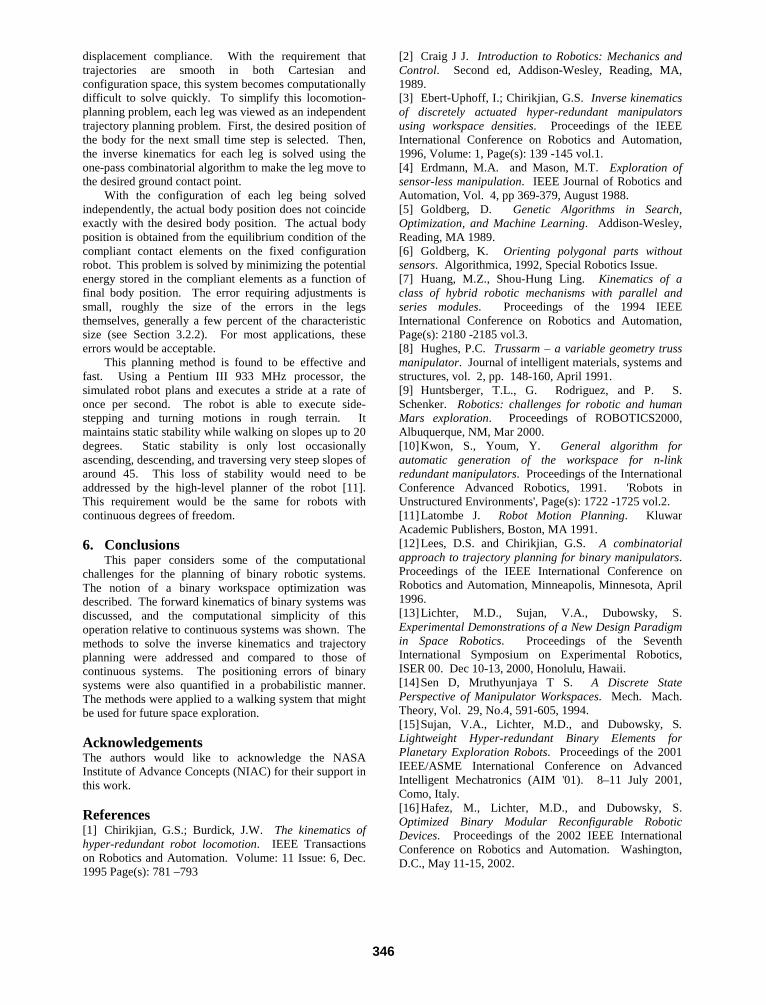
This planning method is found to be effective andfast. Using a Pentium III 933 MHz processor, thesimulated robot plans and executes a stride at a rate ofonce per second. The robot is able to execute side-stepping and turning motions in rough terrain. Itmaintains static stability while walking on slopes up to 20degrees. Static stability is only lost occasionallyascending, descending, and traversing very steep slopes ofaround 45. This loss of stability would need to beaddressed by the high-level planner of the robot [11].This requirement would be the same for robots withcontinuous degrees of freedom.
6. ConclusionsThis paper considers some of the computational
challenges for the planning of binary robotic systems.The notion of a binary workspace optimization wasdescribed. The forward kinematics of binary systems wasdiscussed, and the computational simplicity of thisoperation relative to continuous systems was shown. Themethods to solve the inverse kinematics and trajectoryplanning were addressed and compared to those ofcontinuous systems. The positioning errors of binarysystems were also quantified in a probabilistic manner.The methods were applied to a walking system that mightbe used for future space exploration.
AcknowledgementsThe authors would like to acknowledge the NASAInstitute of Advance Concepts (NIAC) for their support inthis work.
References[1] Chirikjian, G.S.; Burdick, J.W. The kinematics ofhyper-redundant robot locomotion. IEEE Transactionson Robotics and Automation. Volume: 11 Issue: 6, Dec.1995 Page(s): 781 –793
[2] Craig J J. Introduction to Robotics: Mechanics andControl. Second ed, Addison-Wesley, Reading, MA,1989.[3] Ebert-Uphoff, I.; Chirikjian, G.S. Inverse kinematicsof discretely actuated hyper-redundant manipulatorsusing workspace densities. Proceedings of the IEEEInternational Conference on Robotics and Automation,1996, Volume: 1, Page(s): 139 -145 vol.1.[4] Erdmann, M.A. and Mason, M.T. Exploration ofsensor-less manipulation. IEEE Journal of Robotics andAutomation, Vol. 4, pp 369-379, August 1988.[5] Goldberg, D. Genetic Algorithms in Search,Optimization, and Machine Learning. Addison-Wesley,Reading, MA 1989.[6] Goldberg, K. Orienting polygonal parts withoutsensors. Algorithmica, 1992, Special Robotics Issue.[7] Huang, M.Z., Shou-Hung Ling. Kinematics of aclass of hybrid robotic mechanisms with parallel andseries modules. Proceedings of the 1994 IEEEInternational Conference on Robotics and Automation,Page(s): 2180 -2185 vol.3.[8] Hughes, P.C. Trussarm – a variable geometry trussmanipulator. Journal of intelligent materials, systems andstructures, vol. 2, pp. 148-160, April 1991.[9] Huntsberger, T.L., G. Rodriguez, and P. S.Schenker. Robotics: challenges for robotic and humanMars exploration. Proceedings of ROBOTICS2000,Albuquerque, NM, Mar 2000.[10] Kwon, S., Youm, Y. General algorithm forautomatic generation of the workspace for n-linkredundant manipulators. Proceedings of the InternationalConference Advanced Robotics, 1991. 'Robots inUnstructured Environments', Page(s): 1722 -1725 vol.2.[11] Latombe J. Robot Motion Planning. KluwarAcademic Publishers, Boston, MA 1991.[12] Lees, D.S. and Chirikjian, G.S. A combinatorialapproach to trajectory planning for binary manipulators.Proceedings of the IEEE International Conference onRobotics and Automation, Minneapolis, Minnesota, April1996.[13] Lichter, M.D., Sujan, V.A., Dubowsky, S.Experimental Demonstrations of a New Design Paradigmin Space Robotics. Proceedings of the SeventhInternational Symposium on Experimental Robotics,ISER 00. Dec 10-13, 2000, Honolulu, Hawaii.[14] Sen D, Mruthyunjaya T S. A Discrete StatePerspective of Manipulator Workspaces. Mech. Mach.Theory, Vol. 29, No.4, 591-605, 1994.[15] Sujan, V.A., Lichter, M.D., and Dubowsky, S.Lightweight Hyper-redundant Binary Elements forPlanetary Exploration Robots. Proceedings of the 2001IEEE/ASME International Conference on AdvancedIntelligent Mechatronics (AIM '01). 8–11 July 2001,Como, Italy.[16] Hafez, M., Lichter, M.D., and Dubowsky, S.Optimized Binary Modular Reconfigurable RoboticDevices. Proceedings of the 2002 IEEE InternationalConference on Robotics and Automation. Washington,D.C., May 11-15, 2002.
346

Experimental Demonstrations of a NewDesign Paradigm in Space Robotics
Matthew D. Lichter, Vivek A. Sujan, and Steven DubowskyDepartment of Mechanical EngineeringMassachusetts Institute of Technology
Cambridge, MA 02139 USA{lichter | vasujan| dubowsky}@mit.edu
Abstract: This paper presents a study to experimentally evaluate a new designparadigm for robotic components, with emphasis on space robotics applications.In this design paradigm, robotic components are made from embedded binary ac-tuators and compliant mechanisms in order to reduce weight and complexity. Thispaper presents a series of five experiments that demonstrate the concept. Thesestudies include a reconfigurable rocker suspension for rocker-bogie rovers, a sampleacquisition gripper, a pantograph mechanism for robotic legs, an articulated binarylimb, and a hyper-degree-of-freedom mechanism building block.
1. IntroductionFuture missions to planets such as Mars will require explorer/worker robots to per-form tasks of increased complexity such as exploring, mining, conducting scienceexperiments, constructing facilities, and preparing for human explorers. To meet theobjectives of missions in the year 2010 to 2040 timeframe, planetary robots will needto work faster, travel larger distances, and perform highly complex tasks with a highdegree of autonomy [1]. They will also need to cooperate in teams and reconfigurethemselves to meet their mission objectives. Current electromechanical technologiesof motors, optical encoders, gears, bearings, etc. will not be lightweight and robustenough for these robots.
In this research, a new class of building blocks for planetary robots is being stud-ied. These devices, called Articulated Binary Elements (ABEs), consist of compliantmechanisms with large numbers of embedded actuators and sensors. Figure 1 showstwo concepts of the ABE elements. These actuators would be binary (on/off) in natureand could be made from conducting polymer, electrostrictive polymer artificial mus-cle, shape memory alloy, etc. [2,3]. By using hundreds or thousands of very simplebut reliable actuators, one can approximate a continuous robotic system in dexterityand utility. This is analogous to the leap from analog to digital computing. The ad-vantage of binary actuation is the fact that systems can be controlled in the absence offeedback sensing and using only very simple digital electronics, due the robust natureof a two-state actuator. In this work, the feasibility of the ABE concept for planetaryrobots is being studied analytically and experimentally.
This paper presents an overview of a series of five experimental developmentsperformed to establish credibility and feasibility of the concepts of embedded binary
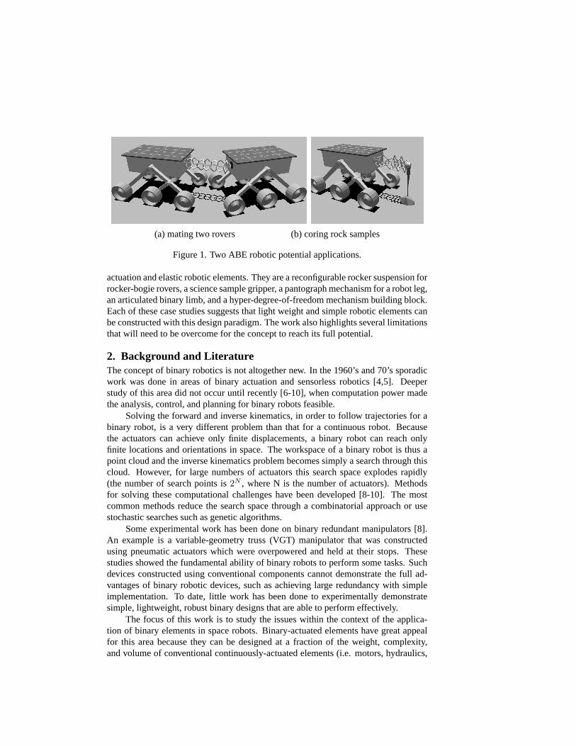
(a) mating two rovers (b) coring rock samples
Figure 1. Two ABE robotic potential applications.
actuation and elastic robotic elements. They are a reconfigurable rocker suspension forrocker-bogie rovers, a science sample gripper, a pantograph mechanism for a robot leg,an articulated binary limb, and a hyper-degree-of-freedom mechanism building block.Each of these case studies suggests that light weight and simple robotic elements canbe constructed with this design paradigm. The work also highlights several limitationsthat will need to be overcome for the concept to reach its full potential.
2. Background and LiteratureThe concept of binary robotics is not altogether new. In the 1960’s and 70’s sporadicwork was done in areas of binary actuation and sensorless robotics [4,5]. Deeperstudy of this area did not occur until recently [6-10], when computation power madethe analysis, control, and planning for binary robots feasible.
Solving the forward and inverse kinematics, in order to follow trajectories for abinary robot, is a very different problem than that for a continuous robot. Becausethe actuators can achieve only finite displacements, a binary robot can reach onlyfinite locations and orientations in space. The workspace of a binary robot is thus apoint cloud and the inverse kinematics problem becomes simply a search through thiscloud. However, for large numbers of actuators this search space explodes rapidly(the number of search points is2N , where N is the number of actuators). Methodsfor solving these computational challenges have been developed [8-10]. The mostcommon methods reduce the search space through a combinatorial approach or usestochastic searches such as genetic algorithms.
Some experimental work has been done on binary redundant manipulators [8].An example is a variable-geometry truss (VGT) manipulator that was constructedusing pneumatic actuators which were overpowered and held at their stops. Thesestudies showed the fundamental ability of binary robots to perform some tasks. Suchdevices constructed using conventional components cannot demonstrate the full ad-vantages of binary robotic devices, such as achieving large redundancy with simpleimplementation. To date, little work has been done to experimentally demonstratesimple, lightweight, robust binary designs that are able to perform effectively.
The focus of this work is to study the issues within the context of the applica-tion of binary elements in space robots. Binary-actuated elements have great appealfor this area because they can be designed at a fraction of the weight, complexity,and volume of conventional continuously-actuated elements (i.e. motors, hydraulics,

etc.) [2,3]. Incorporating the concept of compliant mechanisms enables further de-sign simplifications through the use of elastic flexures in place of mechanical hinges,bearings, and lubrication. The results of this paper suggest that given the developmentof high-performance smart materials and artificial muscle technology, a whole newrealm of robotics design will emerge.
3. Technology Demonstrations3.1. Approach
The goal of this research is to investigate and demonstrate the concept and technolo-gies of achieving high degree of freedom binary systems with physically simple androbust implementations. In this concept the actuators are assumed to be polymer-based materials. These materials include conducting polymers [2] and electrostrictivepolymers [3]. However, while these materials are anticipated to meet the needs of theconcept in the future, they have not yet reached a sufficient state of development to per-form practical experimental demonstrations in devices today. For example, conductingpolymers require immersion in an ion solution and provide only small displacements.So for this research shape memory alloys (SMAs) were chosen as surrogate actuatormaterial.
In all the devices studied, the challenge was to amplify the very small displace-ments provided by the muscle-type actuators. The ABE systems described in thispaper run the range from one-DOF devices to many-DOF systems which use embed-ded actuators and continuously compliant structures.
3.2. Case Studies
3.2.1. Reconfigurable Rocker Suspension
When traversing slopes, a rover can greatly increase its tip over stability by changingthe spread angle of its rockersθ (see Figure 2) [11]. To examine the concept of achiev-ing this with binary actuation, an SMA-actuated rocker was designed and developed(see Figure 3) [12]. The working prototype has demonstrated the feasibility and sim-plicity of such a design. While this first experiment uses conventional bearings andstructural materials, it shows that binary muscle-type actuation in its simplest formcan be effective.
Figure 2. Rover increases tip over stability by reconfiguring its rocker anglesθ1, θ2.

(a) schematic (b) implementation
Figure 3. Reconfigurable rocker.
The working prototype has the performance capabilities required for a real roverdesign. The rocker angle has approximately a 60 degree range of motion (expandingthe rocker angle from 90 degrees to about 150 degrees). This results in a change inheight of the pivot point of 2.75 cm. The lightweight SMAs allow the rocker to lifta 10 kg payload, half the weight of the rover it was designed for. Actuation takes0.5 seconds and consumes less than 1.9 W peak. PID control of the SMAs was alsostudied to examine continuous (non-binary) operation, with good results.
3.2.2. Binary Gripper
In this second device the conventional bearings were replaced by elastic flexurehinges. A one degree-of-freedom binary gripper was designed to show the lightweight, simplicity, and utility of the design concept [12]. This gripper could be usedfor rock sample collection on a space explorer. The gripper has been used for thispurpose on a laboratory rover test bed [13].
When the single SMA wire is actuated, the fingers of the gripper close aroundthe object to be grasped (see Figure 4). The key of the gripper design was to amplifythe small (5%) deformations of the SMA actuator to be large enough to grasp rock
(a) schematic (b) implementation
Figure 4. Binary gripper.

samples, while keeping forces at a usable level. Elastic flexures are incorporated at allthree finger pivots. The compliance of these flexures acts as a return spring to openthe fingers upon release of the object. This device uses no sensors, bearings, or gears.
The gripper with its needle-like fingers and simple binary action is able to reliablygrasp rocks of varying size. The mounting base dimension is 2.5 cm in diameter. Eachfinger is 7.6 cm long, with a motion range of 20 degrees, and can pick up objects upto 5.7 cm in diameter. It can provide a normal force of up to 0.110 N and 0.0422 Nat each finger tip, with a 250 micron and 150 micron SMA wire respectively. Theexpected normal force is 0.149 N and 0.0536 N for the 250 micron and 150 micronwires respectively. The difference in observed verses expected forces can be attributedto wire slip at mounting points, slop in the wire, etc. These observed forces result inreliably lifting objects weighing up to 330 g, six times its own weight of 55 g.
3.2.3. Pantograph Mechanism
A single DOF 4-bar pantograph mechanism was designed to demonstrate large ampli-fication of binary muscle actuator motion (see Figure 5). This amplification is requiredby some ABE applications, such as legged walking machines.
The pantograph mechanism exemplifies some of the advantages of using compli-ant members and is an advance over the previous devices considered. The mechanismis simple, since the flexures and bars can be molded or cut from a single piece of ma-terial. In this case, a laser cutter was used to cut the part from sheet plastic (PETG— polyethylene terephthalate, glycol modified), although other methods coulld havebeen used. Like the previous two studies, this mechanism demonstrates how verysmall actuator motions can be amplified to usable scales in designs. Although SMAactuator technology can achieve usable elongations of only a few percent, this designcan amplify this displacement by a factor of 8 in theory. In the working prototype,the endpoint deflected 29 mm given an actuator contraction of only about 4.5 mm,yielding an amplification of 6.5. The difference between theory and implementationis due mostly to un-modeled compliance in the bars and in irregularities in the SMAactuators.
� � � � � � � �
�
� � � � � � � � � � �
� � � � � �
� � � ! " # $
% & '
( ) * + , - . / 0 1 2 3
4 5 6 7 8 9
(a)schematic (b) implementation
Figure 5. Binary pantograph mechanism.
3.2.4. Articulated Binary Limb (ABL)
A more general Articulated Binary Limb (ABL) was designed to study some of theissues involved with multi-DOF robotic systems [14]. The ABL could be used ina wide variety of space robotic applications, as a dexterous manipulator, as a cam-

(a) full system stowed and deployed
(b) 3-DOF stage
Figure 6. Articulated Binary Limb (ABL).
era or instrument mount, as an articulated connection between cooperating roboticexplorer/workers, etc. (see Figure 1). This device is comprised of a serial chain ofparallel stages (see Figure 6). In the experimental implementation, each 3-DOF stageis composed of three 1-DOF links, each with a shape memory alloy (SMA) actuator.The links are fabricated from polyethylene using high precision water jet cutting. Thelink shape provides for an elastic hinge at the end of each element. The actuationscheme allows for only binary operation of each link. The experimental structure builtconsists of five parallel stages, yielding 15 binary degrees of freedom. The ABL isthus able to achieve215 = 32, 768 discrete configurations. With this many configura-tions, the device can approximate a continuous system in dexterity and utility. By itspolymer construction and binary actuation the design is very lightweight and simple.
In order to actuate and control such a system, based on the desired kinematics,power must be applied to each actuator by a central controller. The large number ofactuators can rapidly make the physical realization of such a system difficult, if eachactuator requires an individual set of power supply lines from the central controller
(a) implementation
� �
� � � � � � � � � � � � � � � � � � � � � � � � � � � ! " # $
% & ' ( ) * + ,
- . / 0 1 2 34 5
(b) power bus architecture
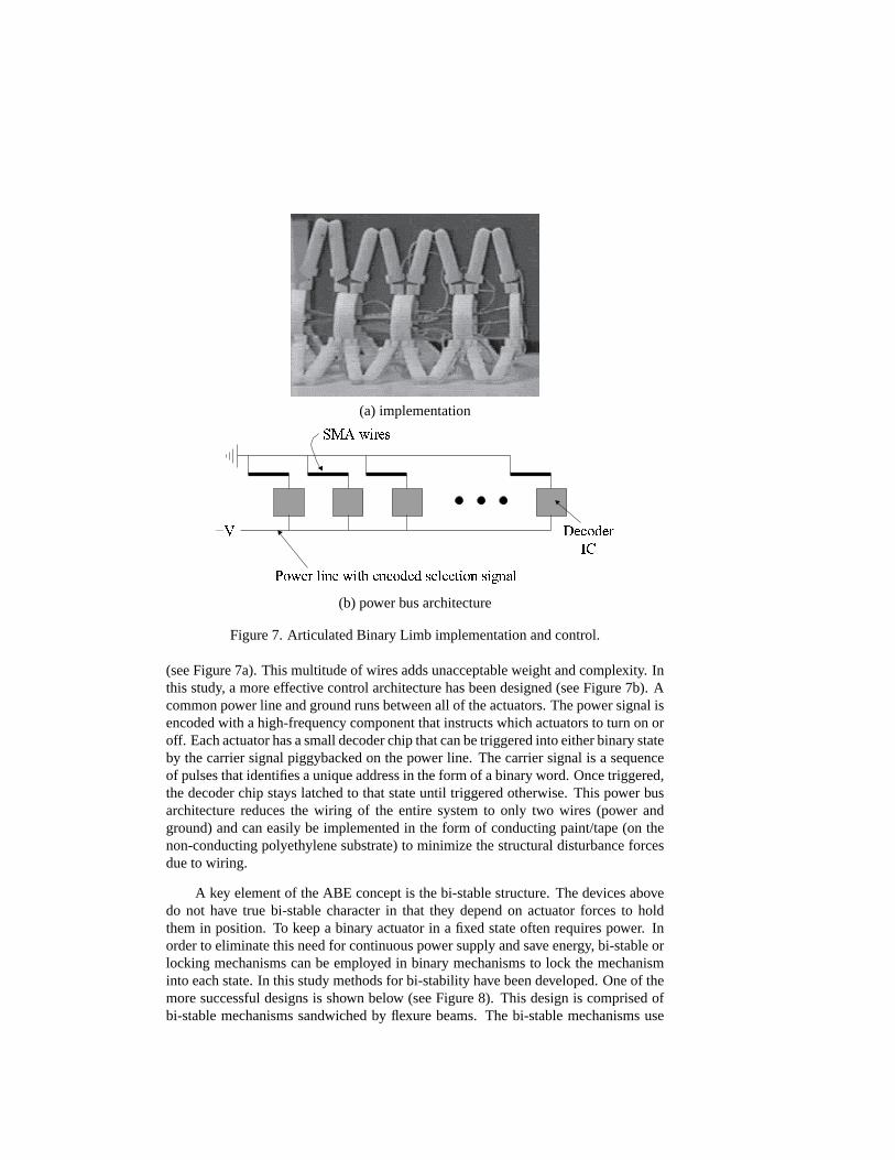
Figure 7. Articulated Binary Limb implementation and control.
(see Figure 7a). This multitude of wires adds unacceptable weight and complexity. Inthis study, a more effective control architecture has been designed (see Figure 7b). Acommon power line and ground runs between all of the actuators. The power signal isencoded with a high-frequency component that instructs which actuators to turn on oroff. Each actuator has a small decoder chip that can be triggered into either binary stateby the carrier signal piggybacked on the power line. The carrier signal is a sequenceof pulses that identifies a unique address in the form of a binary word. Once triggered,the decoder chip stays latched to that state until triggered otherwise. This power busarchitecture reduces the wiring of the entire system to only two wires (power andground) and can easily be implemented in the form of conducting paint/tape (on thenon-conducting polyethylene substrate) to minimize the structural disturbance forcesdue to wiring.
A key element of the ABE concept is the bi-stable structure. The devices abovedo not have true bi-stable character in that they depend on actuator forces to holdthem in position. To keep a binary actuator in a fixed state often requires power. Inorder to eliminate this need for continuous power supply and save energy, bi-stable orlocking mechanisms can be employed in binary mechanisms to lock the mechanisminto each state. In this study methods for bi-stability have been developed. One of themore successful designs is shown below (see Figure 8). This design is comprised ofbi-stable mechanisms sandwiched by flexure beams. The bi-stable mechanisms use

� � � � � � � � � � � � � � � �
� � � � � � � �� � � � � ! " # $
% & ' ( ) *
+ , - . / 0 1 2 3 45 6 7 8 9 : ; < =
> ? @ A B C D EF G H I J K L M N O
P Q R S T U
(a) schematic (b) implementation
Figure 8. Bi-stable mechanism.
detents to passively lock the joint into discrete states, while the flexures add out-of-plane rigidity. The actuators can be mounted to the sides of a joint like this, similarto the musculature of a human elbow or knee. Fabrication of these bi-stable elementsinto the hinges of the ABL (shown in Figure 6) is currently under development.
3.2.5. Hyper-DOF Mechanisms
In the progress of developing the ABE concept, continuously compliant structureswith embedded actuators are being studied with the aim of understanding a basicbuilding block for more complex designs [15]. Embedding a large number of actuatorsinto a continuously compliant structure can achieve unique motion amplifications andshape deformations (see Figure 9). A mechanism with a cellular structure of hundredsof small deformable cells may provide high performance and large ranges of motion.
Structural finite element analyses have been done of various shapes for individ-ual structures, such as beam elements with voided interior volumes, diamond shapedelements, dog legged elements, elbow elements, and hexagonal elements (see Fig-ure 10). This analysis shows the strong relationship between the structure shape anddeformation of the elements.
The manufacture of these elastic elements with embedded actuation is not trivial.In our studies, compliant structures have been cast using different elastomeric materi-als (see Figure 11). Future work will consider such methods as stereolithography orselective laser sintering as possible alternative fabrication methods.
Figure 9. Hyper-DOF network of cells achieving large displacements.

Figure 10. Expected results for various structures.
Figure 11. Hyper-DOF systems: flexible structures with embedded SMAs.
4. Summary
This paper presents an experimental study of a new paradigm for the design and fabri-cation of robotic components, with attention to potential space robotics applications.These robotic components would use embedded binary actuators and elastic memberswith bi-stable elements. These components have the potential to be implemented witha fraction of the weight, volume, cost, and complexity of conventional systems com-posed of motors, bearings, geartrains, and encoders. The results of this study suggestthat these devices would be effective for robotic systems that are capable of accom-plishing space missions of substantial complexity, with flexibility and robustness. Theconcept is currently limited by polymer actuator development, where present tech-nologies possess practical limitations such as high power requirements, low displace-ments, or the need for immersion in solutions.
Acknowledgements
The authors would like to acknowledge the NASA Institute for Advanced Concepts(NIAC) for supporting this research. Also the important contributions of Kate An-drews, Robert Burn, and Guillermo Oropeza (students at MIT) and Sharon Lin (re-search engineer) are acknowledged.

References[1] Weisbin C, Rodriguez G, Schenker P, et al 1999 Autonomous Rover Technology for Mars
Sample Return.International Symposium on Artificial Intelligence, Robotics and Automa-tion in Space (i-SAIRAS’99), 1-10
[2] Madden J D, Cush R A, Kanigan T S, et al 2000 Fast-contracting Polypyrrole Actuators.Synthetic Metals, 113: 185-193
[3] Pelrine R, Kornbluh R, Pei Q, et al 2000 High-speed Electrically Actuated Elastomers withOver 100% Strain.Science, Vol. 287, No. 5454, 836-839
[4] Anderson V C, Horn R C 1967 Tensor Arm Manipulator Design.ASME paper, 67-DE-57[5] Roth B, Rastegar J, Scheinman V 1973 On the Design of Computer Controlled Manipula-
tors.First CISM-IFTMM Symposium on Theory and Practice of Robots and Manipulators,93-113
[6] Goldberg K 1992 Orienting Polygonal Parts Without Sensors.Algorithmica, specialrobotics issue
[7] Canny J, Goldberg K 1993 A RISC Paradigm for Industrial Robotics.Tech. Rep. ESCR 93-4/RAMP 93-2, Engineering Systems Research Center, University of California at Berkeley
[8] Chirikjian G S 1994 A Binary Paradigm for Robotic Manipulators.Proc. IEEE Interna-tional Conf. on Robotics and Automation, 3063-3069
[9] Ebert-Uphoff I, Chirikjian G S 1996 Inverse Kinematics of Discretely Actuated Hyper-Redundant Manipulators Using Workspace Densities.Proc. IEEE International Conf. onRobotics and Automation, 139-145
[10] Lees D S, Chirikjian G S 1996 A Combinatorial Approach to Trajectory Planning forBinary Manipulators.Proc. IEEE International Conf. on Robotics and Automation, 2749-2754
[11] Iagnemma K, Rzepniewski A, Dubowsky S, et al 2000 Mobile Robot Kinematic Recon-figurability for Rough-Terrain.Proceedings of the SPIE Symposium on Sensor Fusion andDecentralized Control in Robotic Systems III
[12] Burn R D 1998 Design of a Laboratory Test Bed for Planetary Rover Systems. MasterThesis, Department of Mechanical Engineering, MIT
[13] Iagnemma K, Burn R, Wilhelm E, et al 1999 Experimental Validation of Physics-BasedPlanning and Control Algorithms for Planetary Robotic Rovers.Proceedings of the SixthInternational Symposium on Experimental Robotics, ISER ’99
[14] Oropeza G 1999 The Design of Lightweight Deployable Structures for Space Applica-tions. Bachelor Thesis, Department of Mechanical Engineering, MIT
[15] Andrews E K 2000 Elastic Elements with Embedded Actuation and Sensing for Use inSelf-Transforming Robotic Planetary Explorers. Master Thesis, Department of MechanicalEngineering, MIT.
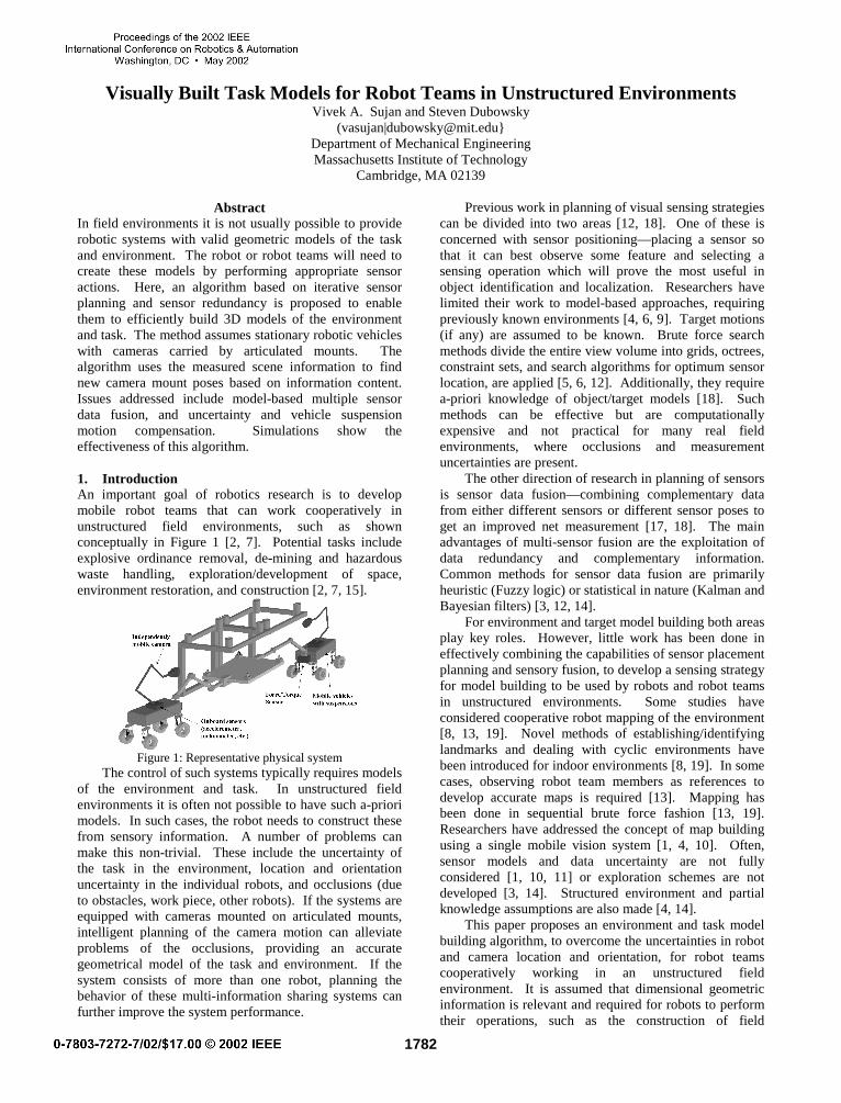
Visually Built Task Models for Robot Teams in Unstructured EnvironmentsVivek A. Sujan and Steven Dubowsky
(vasujan|[email protected]}Department of Mechanical EngineeringMassachusetts Institute of Technology
Cambridge, MA 02139
AbstractIn field environments it is not usually possible to providerobotic systems with valid geometric models of the taskand environment. The robot or robot teams will need tocreate these models by performing appropriate sensoractions. Here, an algorithm based on iterative sensorplanning and sensor redundancy is proposed to enablethem to efficiently build 3D models of the environmentand task. The method assumes stationary robotic vehicleswith cameras carried by articulated mounts. Thealgorithm uses the measured scene information to findnew camera mount poses based on information content.Issues addressed include model-based multiple sensordata fusion, and uncertainty and vehicle suspensionmotion compensation. Simulations show theeffectiveness of this algorithm.
1. IntroductionAn important goal of robotics research is to developmobile robot teams that can work cooperatively inunstructured field environments, such as shownconceptually in Figure 1 [2, 7]. Potential tasks includeexplosive ordinance removal, de-mining and hazardouswaste handling, exploration/development of space,environment restoration, and construction [2, 7, 15].
Figure 1: Representative physical systemThe control of such systems typically requires models
of the environment and task. In unstructured fieldenvironments it is often not possible to have such a-priorimodels. In such cases, the robot needs to construct thesefrom sensory information. A number of problems canmake this non-trivial. These include the uncertainty ofthe task in the environment, location and orientationuncertainty in the individual robots, and occlusions (dueto obstacles, work piece, other robots). If the systems areequipped with cameras mounted on articulated mounts,intelligent planning of the camera motion can alleviateproblems of the occlusions, providing an accurategeometrical model of the task and environment. If thesystem consists of more than one robot, planning thebehavior of these multi-information sharing systems canfurther improve the system performance.
Previous work in planning of visual sensing strategiescan be divided into two areas [12, 18]. One of these isconcerned with sensor positioning—placing a sensor sothat it can best observe some feature and selecting asensing operation which will prove the most useful inobject identification and localization. Researchers havelimited their work to model-based approaches, requiringpreviously known environments [4, 6, 9]. Target motions(if any) are assumed to be known. Brute force searchmethods divide the entire view volume into grids, octrees,constraint sets, and search algorithms for optimum sensorlocation, are applied [5, 6, 12]. Additionally, they requirea-priori knowledge of object/target models [18]. Suchmethods can be effective but are computationallyexpensive and not practical for many real fieldenvironments, where occlusions and measurementuncertainties are present.
The other direction of research in planning of sensorsis sensor data fusion—combining complementary datafrom either different sensors or different sensor poses toget an improved net measurement [17, 18]. The mainadvantages of multi-sensor fusion are the exploitation ofdata redundancy and complementary information.Common methods for sensor data fusion are primarilyheuristic (Fuzzy logic) or statistical in nature (Kalman andBayesian filters) [3, 12, 14].
For environment and target model building both areasplay key roles. However, little work has been done ineffectively combining the capabilities of sensor placementplanning and sensory fusion, to develop a sensing strategyfor model building to be used by robots and robot teamsin unstructured environments. Some studies haveconsidered cooperative robot mapping of the environment[8, 13, 19]. Novel methods of establishing/identifyinglandmarks and dealing with cyclic environments havebeen introduced for indoor environments [8, 19]. In somecases, observing robot team members as references todevelop accurate maps is required [13]. Mapping hasbeen done in sequential brute force fashion [13, 19].Researchers have addressed the concept of map buildingusing a single mobile vision system [1, 4, 10]. Often,sensor models and data uncertainty are not fullyconsidered [1, 10, 11] or exploration schemes are notdeveloped [3, 14]. Structured environment and partialknowledge assumptions are also made [4, 14].
This paper proposes an environment and task modelbuilding algorithm, to overcome the uncertainties in robotand camera location and orientation, for robot teamscooperatively working in an unstructured fieldenvironment. It is assumed that dimensional geometricinformation is relevant and required for robots to performtheir operations, such as the construction of field
1782
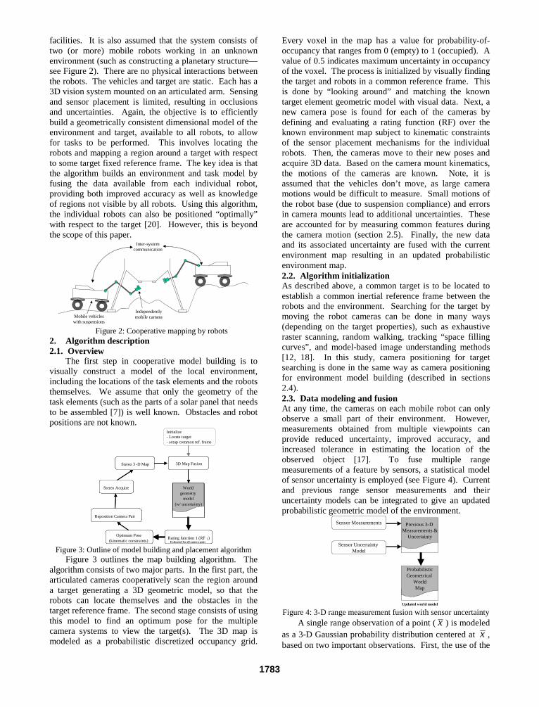
facilities. It is also assumed that the system consists oftwo (or more) mobile robots working in an unknownenvironment (such as constructing a planetary structure—see Figure 2). There are no physical interactions betweenthe robots. The vehicles and target are static. Each has a3D vision system mounted on an articulated arm. Sensingand sensor placement is limited, resulting in occlusionsand uncertainties. Again, the objective is to efficientlybuild a geometrically consistent dimensional model of theenvironment and target, available to all robots, to allowfor tasks to be performed. This involves locating therobots and mapping a region around a target with respectto some target fixed reference frame. The key idea is thatthe algorithm builds an environment and task model byfusing the data available from each individual robot,providing both improved accuracy as well as knowledgeof regions not visible by all robots. Using this algorithm,the individual robots can also be positioned “optimally”with respect to the target [20]. However, this is beyondthe scope of this paper.
Mobile vehicleswith suspensions
Independentlymobile camera
Inter-systemcommunication
Figure 2: Cooperative mapping by robots2. Algorithm description2.1. Overview
The first step in cooperative model building is tovisually construct a model of the local environment,including the locations of the task elements and the robotsthemselves. We assume that only the geometry of thetask elements (such as the parts of a solar panel that needsto be assembled [7]) is well known. Obstacles and robotpositions are not known.
World geometry
model (w/ uncertainty)
Rating function 1 (RF 1)
3-D Map FusionStereo 3 -D Map
Stereo Acquire
Optimum Pose (kinematic constraints)
Reposition Camera Pair
Evaluated for all camera pairs
World geometry
model (w/ uncertainty)
World geometry
model (w/ uncertainty)
Rating function 1 (RF 1)
3D Map FusionStereo 3 -D Map
Stereo Acquire
Optimum Pose (kinematic constraints)
Reposition Camera Pair
Evaluated for all camera pairs
Initialize- Locate target- setup common ref. frame
Figure 3: Outline of model building and placement algorithmFigure 3 outlines the map building algorithm. The
algorithm consists of two major parts. In the first part, thearticulated cameras cooperatively scan the region arounda target generating a 3D geometric model, so that therobots can locate themselves and the obstacles in thetarget reference frame. The second stage consists of usingthis model to find an optimum pose for the multiplecamera systems to view the target(s). The 3D map ismodeled as a probabilistic discretized occupancy grid.
Every voxel in the map has a value for probability-of-occupancy that ranges from 0 (empty) to 1 (occupied). Avalue of 0.5 indicates maximum uncertainty in occupancyof the voxel. The process is initialized by visually findingthe target and robots in a common reference frame. Thisis done by “looking around” and matching the knowntarget element geometric model with visual data. Next, anew camera pose is found for each of the cameras bydefining and evaluating a rating function (RF) over theknown environment map subject to kinematic constraintsof the sensor placement mechanisms for the individualrobots. Then, the cameras move to their new poses andacquire 3D data. Based on the camera mount kinematics,the motions of the cameras are known. Note, it isassumed that the vehicles don’t move, as large cameramotions would be difficult to measure. Small motions ofthe robot base (due to suspension compliance) and errorsin camera mounts lead to additional uncertainties. Theseare accounted for by measuring common features duringthe camera motion (section 2.5). Finally, the new dataand its associated uncertainty are fused with the currentenvironment map resulting in an updated probabilisticenvironment map.2.2. Algorithm initializationAs described above, a common target is to be located toestablish a common inertial reference frame between therobots and the environment. Searching for the target bymoving the robot cameras can be done in many ways(depending on the target properties), such as exhaustiveraster scanning, random walking, tracking “space fillingcurves”, and model-based image understanding methods[12, 18]. In this study, camera positioning for targetsearching is done in the same way as camera positioningfor environment model building (described in sections2.4).2.3. Data modeling and fusionAt any time, the cameras on each mobile robot can onlyobserve a small part of their environment. However,measurements obtained from multiple viewpoints canprovide reduced uncertainty, improved accuracy, andincreased tolerance in estimating the location of theobserved object [17]. To fuse multiple rangemeasurements of a feature by sensors, a statistical modelof sensor uncertainty is employed (see Figure 4). Currentand previous range sensor measurements and theiruncertainty models can be integrated to give an updatedprobabilistic geometric model of the environment.
ProbabilisticGeometrical
WorldMap
Sensor Measurements
Sensor Uncertainty Model
Previous 3-D Measurements &
Uncertainty
Updated world model
Figure 4: 3-D range measurement fusion with sensor uncertaintyA single range observation of a point ( x ) is modeled
as a 3-D Gaussian probability distribution centered at x ,based on two important observations. First, the use of the
1783

mean and covariance of a probability distribution functionis a reasonable form to model sensor data and is a secondorder linear approximation [17]. This linearapproximation corresponds to the use of a Gaussian(having all higher moments of zero). Second, based onthe central limit theorem, the sum of a number ofindependent variables has a Gaussian distributionregardless of their individual distributions.
The standard deviations along the three axes of thedistribution correspond to estimates of the uncertainty inthe range observation along these axes. These standarddeviations are a function of intrinsic sensor parameters(such as camera lens shape accuracy) as well as extrinsicsensor parameters (such as the distance to the observedpoint or feature). This model can be theoreticallyapproximated as [20]:
( )n
zyx
zyx
dTS
f
⋅⋅≈
=
,,
,, parameters intrinsic ,parameters extrinsicσ (1)
where S is an intrinsic parameter uncertainty constant,Tx,y,z is an extrinsic parameter uncertainty constant, d isthe distance to the feature/environment point, and n is aconstant (typically 2). Provided two observations aredrawn from a normal distribution, the observations can bemerged into an improved estimate by multiplying thedistributions. Since the result of multiplying twoGaussian distributions is another Gaussian distribution,the operation is symmetric, associative, and can be usedto combine any number of distributions in any order. Thecanonical form of the Gaussian distribution in ndimensions depends on the standard distributions, σx,y,z, acovariance matrix (C) and the mean ( x ) [17]:
( )( ) ( )
=
′−′−−=′ −
2
2
2
1
2 where,
2
1exp
2
1)(
zzyzx
zyyyx
zxyxx
T
n CxxCxxC
xp
σσρσσρσ
σρσσσρσ
σρσσρσσ
π
(2)
where the exponent is called the Mahalanobis distance.For un-correlated measured data ρ=0. The formulation inEquation 2 is in the spatial coordinate frame. However,all measurements are made in the camera (or sensor)coordinate frame. This problem is addressed through atransformation of parameters from the observation frameto the spatial reference frame as follows:
)()(dtransforme θθ −⋅⋅−= RCRC T (3)
where R(θ)θ)θ)θ) is the rotation matrix between the twocoordinate frames. The angle of the resulting principalaxis can be obtained from the merged covariance matrix:
+
−=21
11merged 1
CC
CCC (4)
where Ci is the covariance matrix associated with the ith
measurement. Additionally, a translation operation isapplied to the result from Equation 2, to bring the resultinto the spatial reference frame.2.4. Definition of the rating function (RF)A rating function is used to determine the next pose of thecamera from which to look at the unknown environment.The aim is to acquire new information of the environmentthat would lead to a more detail and more extensive
environment map. In selecting this new camera state thefollowing four constraints are considered:(i) Goal configuration is collision free—from the
probabilistic geometric environment model, (x,y,z)locations with Px,y,z < Pempty = 0.05 (2σ) areconsidered as unoccupied. Such points formcandidate configuration space camera posecoordinates.
(ii) Goal reached by a collision free path—this is afunction of the camera manipulator kinematics andthe known environment model.
(iii) Goal configuration should not be far from the currentone—a Euclidean metric in configuration space, withindividual weights αi on each degree of freedom ofthe camera pose c , is used to define the distancemoved by the camera:
21
1
2)(
′−= ∑
=
n
iiii ccd α (5)
where c and c ′ are vectors of the new and currentcamera poses respectively.
(iv) Measurement at the goal configuration shouldmaximize information intake—Specifically, the newinformation (NI) is equal to the expected informationof the unknown/partially known region viewed fromthe camera pose under consideration. This is basedon the known obstacles from the current environmentmodel, the field of view of the camera (see Figure 5)and a framework for entropic thresholding ofinformation. Shannon showed that a definition ofentropy, similar in form to a corresponding definitionin statistical mechanics, can be used to measure theinformation gained from the selection of a specificevent among an ensemble of possible events [16].This entropy function, H, can be represented as:
( ) ∑=
−=n
kkkn qqqqqH
121 ln,...,, (6)
where qk represents the probability of occurrence forthe kth event, and uniquely satisfies the followingthree conditions [16]:
• H(q1, q2,…, qn) is a maximum for qk=1/n for k=1…n.This implies that a uniform probability distributionpossesses the maximum entropy.
• H(AB)=H(A)+HA(B) where A and B are two finiteschemes. H(AB) represents the total entropy ofschemes A and B and HA(B) is the conditionalentropy of scheme B given scheme A.
• H(q1, q2,…, qn,0) = H(q1, q2,…, qn) or any event withzero probability of occurrence in a scheme does notchange the entropy function.
Shannon’s emphasis was in describing the informationcontent of 1-D signals. In 2-D the gray level histogram ofan image can be used to define a probability distribution:
gray1...Nifor / == Nfq ii (7)
where fi is the number of pixels in the image with graylevel i, N is the total number of pixels in the image, andNgray is the number of possible gray levels. With thisdefinition, the entropy of an image for which all the qi are
1784

the same—corresponding to a uniform gray leveldistribution or maximum contrast—is a maximum. Theless uniform the histogram, the lower the entropy.���������������������
���������������������������������������������������������������������������������������������������������������������������������������������������
Known region (from earlier measurements)
������������������������������������
�������Obstacle
Expected new information (NI)
Unknown region
Depth of View
Field of View
Camera
Figure 5: Evaluation of expected new informationIt is possible to extend this idea of entropy to a 3-D
signal—the environment model. In such an instance thescene probability distribution for entropy (information)analysis is still given by Equation 7. However, N is themaximum number of voxels visible by the vision system(limited by the depth of field and the field of view), and fi
is the number of voxels in the scene with gray level i.The possible gray values are defined as follows. For anypreviously sampled spatial voxel, a gray (probabilistic)occupancy value between 0 and 1 is found. Next thevalue, p(x), is modified as follows:
≥∀−′−
<∀−′
=′′
≥∀⋅
<∀⋅=′
0.5)xp( 2
1)x(p1
0.5)xp( 2
1)x(p
)x(p :scaling
0.5)xp( d
1
)xp(
1
0.5)xp( d
1
)xp(-1
1
)x(p :stretching
voxel
voxel
(8a)
where dvoxel is the Euclidean distance of the voxel fromthe camera coordinate frame. This process causes regionswith probability densities closer to 0 or 1 (regions of mostcertainty) to have a reduced effect on the new informationexpected. Regions that have a probability density closerto 0.5 (regions of least certainty of occupancy) arestretched out in the scene probability distribution, thusincreasing the new expected information associated withthose regions. Additionally, for all unknown/unsampledvoxels a gray value between 1 and 2 is defined:
max
1)(d
dxp voxel+= (8b)
where dmax is the maximum distance of any voxel in thecamera field of view to the camera (equal to the depth offield). A uniform discretization of this range of grayvalues may be performed to define Ngray. With thesedefinitions qk (Equation 7) is evaluated and the resultsapplied to Equation 6 resulting in a metric for newinformation (NI). Note that by applying the threeconditions described above, this definition for NI doesbehave in an intuitively correct form. For example, for agiven camera pose, if the field of view is occluded thenNI decreases. If every point in the field of view is knownand is empty then NI=0. NI increases as the number of
unknowns in the field of view increases. Further,Equation 8a results in increasing the new informationexpected with regions that are known with medianprobabilistic values i.e. values that indicate with leastamount of certainty whether a voxel is occupied or not.On the other hand, regions with high probabilistic valuesfor occupancy result in reduced associated information.
To plan the motion consistently, constraints (iii) and(iv) are merged into a unique rating function (RF):
RF = (NI - K . dn ) . (1 – Px,y,z) (9)where K, n are scaling constants. Shorter distancesexhibit a higher rating. This rating function can beevaluated and optimized to find the next most promisingcamera configuration from which to make futuremeasurements of the environment. Although this choiceof rating function is somewhat arbitrary, good resultswere obtained. Additional constraints can also beaccommodated.2.5. Suspension motion correctionA final step is to identify the motion of the camera toallow for data fusion. This process eliminatesmanipulator positioning errors and vehicle suspension
motions. A single spatial point in the base frame, ir , is
related to the image point (ui, vi) by the 4x4transformation matrix g01 (see Figure 6).
g01
Target frameCamera base
frame x
y
z
xy
z
rk(u,v,f)
(u,v)f
Spatial point
Figure 6: Relationship of camera and target framesFor motion calibration we need to identify g01:
[ ]
⋅
=⋅=
1
1 0
x
1
3x13x301 z
i
yi
xi
ii
ii
ii
r
r
r
rfk
vk
uk
01Rg
(10)
where R01 is the rotational matrix, x is the translationvector, f is the camera focal length, and ki is a scalingconstant. For computational reasons it is more convenientto treat the 9 rotational components of R01 as independent(rather than a transcedental relation of 3 independentparameters). Each spatial point gives 3 algebraicequations, but also introduces a new variable, ki—multiplicative constant to extend the ith image point vector(u,v,f)i to the ith spatial point in the camera coordinateframe. ki may be found from the disparity pair of thestereo images. For n points we have:
⋅⋅⋅=
⋅⋅⋅⇒=
1111
fk
vk
uk
1
fk
vk
uk
1
fk
vk
uk
2
2
2
1
1
1
01n
nn
nn
2
22
22
1
11
11
01 zn
yn
xn
z
y
x
z
y
x
r
r
r
r
r
r
r
r
r
grgu
(11)
This set of linear equations can be readily solved usingconventional techniques. A least mean square error
1785

solution is given by:
( ) T1T01 rrrug
−= (12)
The rotation matrix, R01, and the translation vector, x, ofthe camera frame with respect to the base frame areextracted directly from this solution of g01. However, forreal measured data and associated uncertainty, a largernumber of scene points are required to more correctlyidentify the geometric transformation matrix, g01. Giventhe (i+1)st scene and image point, from Equation 12 Ri+1
and xi+1 can be obtained. A recursive method can be usedto determine the mean and covariance of x and R01 basedon the previous i measurements as follows:
( )
[ ][ ]
( )
[ ][ ]1
ˆˆ
1
ˆˆ
1
ˆˆ
1
ˆˆ
),(1
),(1
),(1
),(1
),(),(
1
),(1
),(),(
1
11111
11
+−−+
=
++
=
+−−+
=
++
=
+++++
++
+++++
++
i
iCC
i
i
i
xxxxiCC
i
xxix
Tmli
mli
mli
mli
mliml
i
mli
mliml
i
T
iiiixix
i
iii
RRRR
RRR
RR
(13)
Finally, the issue of obtaining appropriate spatialpoints for vehicle motion compensation is addressed.Spatial points are obtained by maintaining a finite set offiducials that are tracked during map building and visibleby the cameras. As the camera moves, the fiducials moverelative to the camera, eventually moving out of thecamera view. This requires methods to track and identifynew fiducials. First, for the purposes of this studyfiducials are tracked using a computationally fast regiongrowing method. Second, new fiducials are selected fromthe probabilistic environment model based on the degreeof certainty with which a sampled point is known.Specifically, all local peaks in the probabilistic geometricenvironment map (potential fiducials) are identified.Next, at each local peak a process called sphericalexpansion is performed. In spherical expansion, usinglocal gradient decent on neighboring voxels, the largestspherical region around a local peak, beyond which thevoxel values increase, is found. Lastly, expanded spheresare scored based on the product of their radii andmagnitude of local peak. These scores are normalizedbased on their distance to the current camera position.Higher scoring peaks form better fiducials and areselected accordingly. Although, alternative scoringfunctions may be employed, this simple one proves highlyeffective. Note that, by knowing the camera position andthe camera arm kinematics, the robot base position can beeasily extrapolated.
3. Simulation resultsResults using the rating function, to explore a planarenvironment and develop a probabilistic geometricenvironment model, are given here. Figure 7 shows theresults obtained of scanning a planar environment ofrandom obstacles. Two vision systems fuse 200 sampleseach to give the probabilistic map seen in Figure 7(b). Byincreasing the number of scans taken, the uncertainty inthis probabilistic map decreases.
(a) Simulated environment
(b) Probabilistic environment map after 400 scansFigure 7: Mapping a simulated planar environment
Table 1: Comparison of explored space after 32 scansSearchmethod
Farthestvisual pointfrom start
Average radialdistance from
start
σσσσ ofviewedspace
Random(m=10)
54.89 26.74 11.48
Random(m=50)
47.34 23.79 9.91
Random(m=100)
46.69 23.57 9.17
Random(m=200)
46.01 22.81 9.42
Random(m=300)
36.62 20.69 7.85
Exhaustive 34.59 19.23 7.52
0 5 10 15 20 25 30 350
1
2
3
4
5
6
7
8
9
Number of camera positions
% o
f wor
ld v
iew
ed
Exhaustive search Random walk - m=300Random walk - m=200Random walk - m=100Random walk - m=50 Random walk - m=10 Raster scan mapping
Figure 8: Percentage of environment viewedThe rating function (RF) cannot be optimized analytically.In practice, finding an optimum value for RF requiresexhaustive searching though the entire knownconfiguration space—a process that takes 0(n) time,where n is the number of discrete points in theconfiguration space. One way to reduce the search time is
1786
to employ a finite random selection of goalconfigurations. For m possible configurations, thisprocess takes 0(m) time—m is a constant. Thus, whilethe best goal configuration would be the one maximizingRF, any configuration with a high value for RF shouldsuffice. Such a configuration can be found withreasonable effort. For comparison, results from randomsample selection using 10, 50, 100, 200, and 300 pointsare presented along with an exhaustive search, in Figure 8and table 1. Note that as the number of search points inthe random selection increases, the explored/viewed spacegrows more uniformly (measured as the standarddeviation of the radius of every point in the viewedenvironment space). This reaches a threshold as thesearch becomes more exhaustive in nature. Figure 8shows the percentage increase of the environment viewedas a function of the number of scans. From this it appearsthat the effects of random walk searches produceequivalent results as an exhaustive search. Additionally,for comparison Figure 8 presents the results of modelingthe environment using a conventional raster scan (wherethe next viewing position is selected sequentially from theavailable poses of the known environment). Clearly,there is significant decrease in performance efficiency.The specific numbers presented here are a function ofcamera properties (such as the FOV and the DOF) and theenvironment obstacles, and should be used to reflect thetrend, not the exact behavior.
4. ConclusionsIn field environments it is often not possible to providerobotic teams with detailed a priori environment and taskmodels. In such unstructured environments, cooperatingrobots will need to create a dimensionally accurate 3-Dgeometric model by performing appropriate sensoractions. However, uncertainties in robot locations andsensing limitations/occlusions make this difficult. A newalgorithm based on iterative sensor planning and sensorredundancy is proposed to build a geometricallyconsistent dimensional map of the environment formobile robots that have articulated sensors. Thisalgorithm is unique in that it uses a metric of the qualityof information previously obtained by the sensors to findnew viewing positions for the cameras. Simulations showpromising results.
5. References1. Asada, M. Map building for a mobile robot from sensorydata. IEEE Transactions on Systems, Man, and Cybernetics.Vol. 37, no. 6, November/December 1990.2. Baumgartner, E.T., P. S. Schenker, C. Leger, and T. L.Huntsberger. Sensor-fused navigation and manipulation from aplanetary rover. Proceedings SPIE Symposium on SensorFusion and Decentralized Control in Robotic Systems, Vol.3523, Boston, MA, Nov 1998.3. Betge-Brezetz, S., Hebert, P., Chatila, R., and Devy, M.Uncertain map making in natural environments. Proceedings ofthe 1996 IEEE International Conference on Robotics andAutomation, Minneapolis, Minnesota, April, 1996.4. Burschka, D. Eberst, C. and Robl, C. Vision based modelgeneration for indoor environments. Proceedings of the 1997
IEEE International Conference on Robotics and Automation,Albuquerque, New Mexico, April, 19975. Connolly, C.I. The determination of the next best views.Proceedings of the IEEE International Conference on Roboticsand Automation, pp. 432-435, 1985.6. Cowan, G.K. and Kovesi, P.D. Automatic sensorplacement from vision task requirements. IEEE Transactions onPattern Analysis and Machine Intelligence, vol. 10, no. 3, pp.407-416, May 1988.7. Huntsberger, T.L. Autonomous multi-rover system forcomplex planetary retrieval operations. Proceedings. SPIESymposium on Sensor Fusion and Decentralized Control inAutonomous Robotic Agents, Pittsburgh, PA, Oct 1997, pp.220-229.8. Jennings, C., Murray, D., and Little, J. Cooperative robotlocalization with vision-based mapping. Proceedings of the1999 IEEE International Conference on Robotics andAutomation, Detroit, Michigan, May 1999.9. Kececi, F., Tonko, M., Nagel, H.H., and Gengenbach, V.Improving visually servoed disassembly operations by automaticcamera placement. Proceedings of the 1998 IEEE InternationalConference on Robotics and Automation, Leuven Belgium.May 1998.10. Kruse, E., Gutsche, R., and Wahl, F.M. Efficient, iterative,sensor based 3-D map building using rating functions inconfiguration space. Proceedings of the 1996 IEEEInternational Conference on Robotics and Automation,Minneapolis, Minnesota, April, 1996.11. Lumelsky, V., Mukhopadhyay, S. and Sun, K. Sensor-based terrain acquisition: the “sightseer” strategy. Proceedingsof the 28th Conference on Decision and Control. Tampa,Florida. December 1989.12. Luo, R.C. and M.G. Kay. Multisensor integration andfusion in intelligent systems. IEEE Transactions on Systems,Man, and Cybernetics, Vol. 19, No. 5, September, 1989.13. Rekleitis, I., Dudek, G., and Milios, E. Multi-robotcollaboration for robust exploration. Proceedings of the 2000IEEE International Conference on Robotics and Automation,San Francisco, CA. April, 2000.14. Repo, T. and Roning, J. Modeling structuredenvironments by a single moving camera. Proceedings. SecondInternational Conference on 3-D Digital Imaging and Modeling,1999. On page(s): 340 - 347,4-8 Oct. 199915. Shaffer, G.; Stentz, A. A robotic system for undergroundcoal mining. Proceedings of the IEEE International Conferenceon Robotics and Automation, 1992. Pages(s): 633 -638 vol.116. Shannon, C. E. A mathematical theory of communication.The Bell System Technical Journal, vol. 27, pp. 379-423 and623-656, July and October, 1948.17. Smith, R.C. and Cheeseman, P. On the representation andestimation of spatial uncertainty. International Journal ofRobotics Research. 5(4): 56-6818. Tarabanis, K.A., Allen, P.K. and Tsai, R.Y. A survey ofsensor planning in computer vision. IEEE Transactions onRobotics and Automation, Vol. 11 no. 1, Pp. 86-104.February, 1995.19. Thrun, S., Burgard, W., and Fox, D. A real-time algorithmfor mobile robot mapping with applications to multi-robot and3D mapping. Proceedings of the 2000 IEEE InternationalConference on Robotics and Automation. San Francisco, CA,April, 2000.20. Sujan, V.A. Compensating for Uncertainty in the Controlof Cooperative Robots in Field Environments. Ph.D. Thesis,Department of Mechanical Engineering, Massachusetts Instituteof Technology, June 2002.
1787

Lightweight Hyper-redundant Binary Elementsfor Planetary Exploration Robots
Vivek A. Sujan, Matthew D. Lichter and Steven DubowskyDepartment of Mechanical EngineeringMassachusetts Institute of Technology
Cambridge, MA 02139
33
Abstract--This paper presents the design of a new lightweight,hyper-redundant, deployable Binary Robotic ArticulatedIntelligent Device (BRAID), for space robotic systems. TheBRAID element is intended to meet the challenges of futurespace robotic systems that need to perform more complex tasksthan are currently feasible. It is lightweight, has a high degreeof freedom and a large workspace. The device is based onembedded muscle type binary actuators and flexure linkages.Such a system may be used for a wide range of tasks, andrequires minimal control computation and power resources.
Index terms—Binary robot, hyper-redundant, polymeractuator
I. INTRODUCTION
Future missions to explore Mars will require robots toperform complex tasks such as scouting, mining, conductingscience experiments, and constructing facilities, for humanexplorers and settlers [13]. To accomplish these objectives,future planetary robotic systems will need to work faster,travel larger distances, perform highly complex operations,and work with a higher degree of autonomy than today’stechnology would permit. New design concepts arerequired to meet these challenges. For example, robots willrequire devices for deploying communication antennas,rapid positioning of scientific sensors and facilitatingassembly [13]. A single, yet lightweight and simple devicethat could perform a number of these tasks would be highlydesirable. It would need to have fine motion resolution, alarge motion workspace, multiple degrees of freedom,control simplicity, and have a small stowed volume.
This paper presents the design of an element that is intendedto meet these requirements. This device, called a BinaryRobotic Articulated Intelligent Device (BRAID), consists ofcompliant mechanisms with large numbers of embeddedactuators. Figure 1 shows two potential applicationconcepts of the BRAID element. In some ways it resemblesdeployable systems that have been used in the past for suchspace applications as: deployable booms, solar arrays,antennas, articulated masts and others [4, 7, 18, 22]. Thesedevices can be deployed from a small package into
127127
relatively large structures. However, in general thesestructures are not controllable in terms of being able toassume different commanded configurations. Oncedeployed they are usually not retractable. They are alsousually constructed from heavy and complex components,such as gears, motors, cables, etc., although there are somenotable exceptions [3, 20].
(a) mating two rovers (b) coring rock samplesFigure 1. Two BRAID robotic potential applications
In the robotic research community, efforts have been madeto develop concepts of simple manipulators with goodperformance. An interesting example is binarymanipulators [5, 12, 15]. In this concept, a manipulator iscontrolled by activating the actuators that can assume onlyone of two states (“on” or “off”). The joint level control isvery simple. By simply activating the given actuator in thesystem a discrete change in state is obtained. Often, thecontrol does not require feedback sensors. The two statesare the extreme positions of the actuator. Examples includepistons, solenoids or motors. This form of control has beenclassified as sensor-less manipulation [6, 10, 15].
As the number of binary actuators in the system increases,the capabilities of the device approaches that of aconventional continuous manipulator. This is analogous tothe revolution of the digital computer replacing the analogcomputer. However, this leads to mechanisms withcomplex system kinematics. Studies of the kinematics andcontrol of such “hyper-redundant” manipulators, both withand without binary actuation have been performed [2, 5, 11,12, 14].
This paper presents the design of a new lightweight, hyper-redundant, deployable Binary Robotic ArticulatedIntelligent Device (BRAID) for space robotic systems. TheBRAID element is made of a serial chain of parallel stages(see Figure 2). Each three DOF stage has three flexure-

based legs, each with muscle type binary actuators. In theexperimental system described in this paper these are shapememory alloy (SMA) actuators. As discussed later, morepromising polymer actuators are now being implemented inthis study. Muscle actuation allows binary operation ofeach leg. The flexures are simple and light weight. Thistype of structure could be used in space robotics as aninstrument positioning device, a highly articulatedmanipulator, a deployable boom (for solar arrays andantennas), etc. The experimental BRAID built consists offive parallel stages, yielding 15 binary degrees of freedom.Thus it has 215 (32,768) discrete configurations. Thus, thesystem can approximate a continuous system in dexterityand utility. By its polymer construction and binaryactuation the design is very lightweight and simple,appropriate for space exploration systems.
This paper is divided as follows: Section 2 describes theparallel link stage design of the BRAID element. Section 3presents a discussion of its actuators and the actuatorcontrol. Section 4 explains the forward kinematics of theBRAID. Section 5 presents two approaches for solving itsinverse kinematics.
Figure 2: Basic design of the BRAID element
II. MANIPULATOR PARALLEL LINK STAGE DESIGN
Figure 3(a) shows one stage of the BRAID element. Eachparallel link stage has three legs and actuators. Each leg hasthree flexure joints—two one DOF joints and one two DOFjoint. This results in four non-intersecting axes per leg:three in parallel and a fourth orthogonal to the first three.Coupling the three legs together (symmetrically 120° apart)gives the parallel link stage three DOF mobility (verticaltranslation, pitch, and yaw). If each leg has only oneactuator (an SMA wire in tension) the restoration force tochange the binary states is provided by the elastic flexurejoints. A pair of antagonistic actuators does not require theelastic effect. Detents help lock each binary leg into adiscrete state (see Figure 3(b)) and provide more accurateand repeatable positioning. They also eliminate the needfor power while the BRAID is stationary.
12712
Flexur e to allow lateral motion of the links 2 DOF Flexure Joint
1 DOF Flexure Joints
Muscle-typeActuators
flexure SMAbi-stableelements
SMA fixture
detent
flexure SMAbi-stableelements
SMA fixture
detent
(a) parallel link stage (b) detent based binary jointFigure 3: Parallel link stage of BRAID
The concept of using flexures to replace hinges andbearings is not new. Short plastic hinges can commonly beseen in commercial applications such as cabinet doors, toolbox lids, shampoo bottle caps, etc. Their design requirescareful attention to their structure mechanics. In theBRAID application large range of motions and lowstiffnesses are desired, and fatigue strength proves to becritical. Repeated bending of a flexure can cause fatiguefailure. The relationship between performance and fatiguelife can be seen by considering a simple beam of thickness t,with Young’s modulus E, bent elastically to a radius of R.The surface strain and maximum elastic stress is given by:
R
t
R
t
2E and
2== σε (1)
This stress must not exceed the fatigue yield strength of thematerial, σf. Hence, the minimum bend radius is given by:
=
≥
M
tEtR
f
1
22 σ (2)
Materials that can be bent to the smallest radius or the oneswhere M (defined in Equation 2) is maximized aredesirable because they give the largest range of motion.Literature suggests the best choices are polymeric materialsand elastomers with M equal to 3x10⁻² [1]. Materials suchas polyethylene, polypropylene and nylon fall into thiscategory. For comparison, for spring steel M equals 0.5x10-
2 (which would be appropriate when high stiffness and smallrange of motion is desired). An ultra high molecular weightpolyethylene was chosen here, based on its machinability,fatigue life, stiffness, weight, and cost.
The experimental system constructed is shown in Figure 4.It consists of five parallel link stages coupled serially,giving a 5 DOF end-effector. This device has yet to have itsdetents installed. With binary control this structure has 23x5
(or 32768) possible states giving the device suitablefreedom for a number of applications. For otherapplications this could be extended to 10 or 20 stages giving23x20 (approximately 1018) possible states. While thisclosely approximates a continuous workspace, it leads tosome interesting inverse kinematic problems due to thehyper-redundancy of the system, see Section 5.
474

Figure 4: Experimental platform of BRAID
III. ACTUATOR AND ACTUATOR CONTROL
For some applications, a hyper-redundant BRAID wouldneed a large number of actuators. The actuators areassumed to be polymer-based smart materials. Thesematerials include conducting polymers and electrostrictivepolymers [17, 21]. However, while these materials areanticipated to meet the needs of the concept in the future,they have not yet reached a sufficient state of developmentto perform practical experimental demonstrations in devicestoday. In the near term, shape memory alloys (SMAs) arebeing used for the muscle actuators. SMAs are a class ofalloys which are able to remember their shape and are ableto return to that shape after being deformed, given a certaintemperature change [8]. These alloys can be used asactuators, as the ratio of the deformation stress to theactuated recovery stress can be higher that 10 to 1. It isproposed that each link be actuated by a pair of antagonisticSMA wires, which open and close the link. Appropriatewire length and thickness are easily determined based on therange of motion and the force output desired. For thislaboratory demonstration, the payload is assumed to be asensor such as a CCD camera weighing less than 50 grams.The stiffness of the antagonistic pair and the flexures mustalso be accounted for. However, the design of the SMAactuators is not a serious challenge.
To actuate the BRAID element, the actuators need to betriggered selectively, as required by the inverse kinematics.Conceptually, such a binary control is simple requiring nosensor feedback. However, the large number of actuatorscan rapidly make the physical realization of such a systemdifficult, if each actuator requires unique power supplylines. A multitude of wiring introduces possibility for errorand would result in additional weight and volume, largeexternal forces, and complexity. The BRAID concept usesa more compact and efficient form of supplying power andcontrol (see Figure 5). A common power line and groundare provided to all the actuators. Each actuator has a small“decoder” chip that can be triggered into either binary stateby a carrier signal “piggybacked” on the power line. Thecarrier signal is a sequence of pulses that identifies a uniqueaddress in the form of a binary word for the actuator thatrequires toggling. This architecture reduces the wiring ofthe entire system to only two wires (see Figure 5). This caneasily be implemented in the form of conducting paint/tape
1212
(on the non-conducting polyethylene substrate). This busarchitecture is currently being implemented.
+V
Power line with encoded selection signal
SMA wires
DecoderIC
(a) Overview of actuator control electronics
(b) Power/Control Bus Decoder ArchitectureFigure 5: SMA Power and Control Bus
IV. FORWARD KINEMATICS
Binary devices present a number of challenges not found inconventional continuous systems. For example, acontinuous robot can reach an infinite number of pointswithin its workspace while a binary robot can only reach afinite number of points. A binary robot’s workspace is thusa discrete point cloud. A BRAID based system adds furtherchallenges, due to the complexity of its kinematics. Atypical four by four homogeneous transformation matrix isformulated as a combination of a rotation matrix and atranslation vector of one coordinate frame with respect toanother. The kinematic variables are then three rotationaland three translational variables (six DOF). In a singleparallel link stage of the BRAID system, the three legs arepositioned about the vertices of two equilateral triangles.Additionally, based on the joint configuration of each leg,the single stage has only three degrees of freedom—pitchand yaw rotations and a vertical translation. In general,given the four by four transformation matrix Ai-1,i, of the ith
coordinate frame with respect to the i-1th coordinate frame(see Figure 6(b)), one can derive the forward kinematics ofthe entire n-staged system. A0n defines the forwardkinematics from base to end-effector of the entire systemand is simply given by:
∏=
−− =⋅⋅⋅=n
iiinnn AAAAAA
1,1,13,22,11,00 (3)
7575

z0
y0
x0
yn
zn
xn
(a) BRAID system frames
low lateral motion of the links
xi-1
yi-1
zi-1
zi
xi
li1
li2
li3
yi
leg length
(b) ith parallel link stageFigure 6: Critical parameter representation of BRAID
system
In this formulation the leg lengths (see Figure 6) are thecontrol variables. The relationship between these leglengths and the pitch, yaw, and vertical translation of the ith
coordinate frame with respect to the i-1th coordinate frame(see Figure 6) can be formulated. This relationship does nothave a closed form solution. Hence, Ai-1,i is only a functionof the variable leg lengths of the ith stage (li
1,2,3). Sinceevery leg in the system can be in only one of two states(binary), each leg length can have only one of two values(defined as lmin and lmax). Hence, each term of Ai-1,i canhave only 8 different discrete values.
Figure 7 shows the workspace generated for a 5 stageBRAID element. The workspace for this example consistsof 215 unique states. However, the workspace is clearlynon-uniform in its distribution. Optimization of thisworkspace in terms of density of reachable states is an areaof continuing research.
127127
Workspace of 5 stage BRAID system
Figure 7: Workspace of 5 stage BRIAD element (BRAIDelement base center=origin)
V. INVERSE KINEMATICS
Once the forward kinematics of the system have beendeveloped, the problem of executing practical tasks requiresthe solution to the inverse kinematics problem. While thehardware costs and control complexity of a binarymanipulator are lower than those of a continuously-actuatedmanipulator, there is a tradeoff in the complexity of thetrajectory planning and inverse kinematics software. Asexpected, the inverse kinematics problem cannot beexpressed in a closed form solution. Brute force orexhaustive search methods may prove appealing for systemswith few stages (less than 5), but become impractical forlarger systems. As the number of degrees of freedomincrease, the complexity of the workspace growsexponentially. For every additional stage there is about anorder of magnitude increase in the number of states in theworkspace. Hence, for large systems more efficient searchmethods are required to find “optimum” solutions. Thissection presents two possible search methods for the inversekinematics problem. The first is a genetic search algorithmand the second is a combinatorial heuristic searchalgorithm. The search metric for both algorithms is tominimize the distance between the end-effector and desiredposition. Both algorithms will be briefly described andtheir results will be presented.
A. Genetic Search Algorithm
Here a classical genetic algorithm approach for finding anoptimum solution is used, where each generation consists ofm-bit binary words describing the manipulator state (wherem is the number of actuators). A full description of geneticalgorithms can be found in [9].
66

B. Combinatorial Heuristic Search Algorithm
This algorithm was first described in [15]. In order to avoidexponential growth of the search space as the number ofactuators grow, the inverse kinematics are solved bychanging the state of only a few actuators at any given time.This is perceived as a k-bit change to the given system state,where any system state is defined by an m-bit word (m is thenumber of actuators). At any state all possible changes (upto k-bits, where k ≤ m) are evaluated to determine the onethat optimizes the search metric (i.e. reduces the errorbetween the end-effector position and the desired position).This optimal change forms the new state of the system andthe search procedure repeats until convergence. This searchmethod reduces the computational complexity from O(2m)to O(mk) or from exponential computational time topolynomial computational time. This is seen through thefollowing observation. For the binary robot beingconsidered with m actuators, moving towards its target bychanging up to k-bits requires a search through
+⋅⋅⋅+
+
k
mmm
10
possible states, where )!(!
!
kmk
m
k
m
−=
.
Expanding these terms, the highest power of m is found tobe k. An exhaustive search of same system would requireexactly 2m search states.
C. Search Algorithm Results
Figure 8 shows the performance of the BRAID withdifferent number of stages (n), using the genetic searchalgorithm, attempting to reach a desired position from aninitial position. The actuated leg length was normalized toone inch. Figure 8 shows that, the steady state errordecreases with increasing n. Note that the absolute errordifference (after convergence) for 12 stages and 17 stages is0.015 inches. Thus, although the number of reachablepoints increases with the number of stages, the accuracy toreach a given point might not increase. As expected of agenetic algorithm, the average error across a givenpopulation decreases with increasing generation.
0 10 20 30 40 50 60 70 80 90 1000
0.5
1
1.5
2
2.5
3
3.5
Generation number
Fitn
ess
= E
rror
(in
ches
)
Plot showing convergence of least error in a generation vs generation number
n=17
n-12
n=6
Figure 8: Results of genetic search algorithm for n-stagedBRIAD element (population size = 30, probability ofcrossover = 0.6, probability of bit-wise mutation = 0.02)Figure 9 shows the performance of the combinatorialheuristic search algorithm, attempting to reach a desiredposition from an initial position. The algorithm was tested
127127
on the BRAID, with variable number of stages. Again, theactuated link length was normalized to one inch. At everysearch step, a search through
+⋅⋅⋅+
+
k
mmm
10 states
was performed (where k=3), giving a new end-effectorposition with less error. From figure 9, it is seen that theerror convergence rate stays fairly constant with increasingsystem complexity (increasing n, the number of parallel linkstages). However, each step needs more computation as
+⋅⋅⋅+
+
k
mmm
10 increases with increasing n.
Additionally, in general the steady state error decreases withthe increasing n. This is expected intuitively since there aremore finite solutions in the workspace. Note again, that theabsolute error difference (after convergence) for 10 stagesand 12 stages is 0.019 inches. Thus, although the numberof reachable points increases with the number of stages, theaccuracy to reach a given point might not increase
1 2 3 4 5 6 7 80
0.5
1
1.5
2
2.5
3
3.5
4Plot showing error convergence vs number of search steps
Index
Err
or (
inch
es)
n=10 n=8 n=6
n=12
Figure 9: Results of combinatorial heuristic searchalgorithm for n-staged BRAID element (maximumallowable bit changes = 3)
VI. CONCLUSIONS
A new lightweight hyper-redundant binary device withpotential application to space robotics systems has beenpresented. Such a system may be used for the deploymentof booms and antennas, rapid and accurate positioning ofsensors, and manipulation requiring simple and highlyarticulated onboard manipulators, all while maintaining asmall stowed volume. This device is comprised of a serialchain of parallel stages and can collapse to a small stowedvolume. Each stage is composed of three flexure-basedelements, each with muscle type actuators, permitting onlybinary operation of each link. Each parallel link stage has 3DOF. By coupling these parallel stages in series, a 5 DOFend-effector pose is obtained. With a large number ofactuators, this system can approximate a continuous systemin dexterity and utility. In such a system, only a binaryword command signal is needed to control the motion of theentire system. Controller feedback and the correspondingcomputational load is completely eliminated. Further, thesystem power bus structure can be implemented so as toeliminate the need for individual power wires to the largearray of actuators. This scheme eliminates all but onepower and one ground line in the system. The system does
77
not have a closed form solution of its forward kinematics.Numerical solutions to the BRAID inverse kinematicsproblem (or trajectory planning), are also presented. Thesesearch techniques were based on a genetic algorithm and acombinatorial heuristic algorithm. Both methods prove tobe highly efficient as compared to exhaustive searchmethods. The workspace of such manipulators and theactuator triggering sequence are areas of current study.Such optimizations would allow for better distributedworkspaces, allowing good dexterity throughout a region.Preliminary experimental results show good promise [16].A detailed discussion of these results are beyond the scopeof this paper.
VII. ACKNOWLEDGEMENTS
The authors would like to acknowledge the NASA Instituteof Advance Concepts (NIAC) for their support in this work.Also the contributions of Guillermo Oropeza (MIT) infabrication of the experimental BRAID is acknowledged[19].
VIII. REFERENCES
[1] Ashby, M. Material selection in mechanical design.Butterworth-Heinemann, Oxford, 1992.
[2] Chirikjian, G.S.; Burdick, J.W. The kinematics of hyper-redundant robot locomotion. IEEE Transactions on Roboticsand Automation. Volume: 11 Issue: 6 , Dec. 1995 Page(s):781 -793
[3] Darby, A. P. and Pellegrino, S. Modeling and control ofa flexible structure incorporating inertial stick-slipactuators. Journal of Guidance, Control, and Dynamics, 22,36-43, 1999.
[4] Dotson RD. Spacecraft deployable structure testing.Space Systems Design and Development Testing (AGARD-CP-561). AGARD. 1995, pp.6/1-12. Neuilly sur Seine,France.
[5] Ebert-Uphoff, I.; Chirikjian, G.S. Inverse kinematics ofdiscretely actuated hyper-redundant manipulators usingworkspace densities. Proceedings of the IEEE InternationalConference on Robotics and Automation, 1996, Volume: 1,Page(s): 139 -145 vol.1.
[6] Erdmann, M.A. and Mason, M.T. Exploration of sensor-less manipulation. IEEE Journal of Robotics andAutomation, Vol. 4, pp 369-379, August 1988.
[7] Gantes, C., Connor, J., and Logcher, R.D. Structuralanalysis and design of deployable structures. Computers andStructures. Vol. 32, No. ¾, pp. 661-669, 1989.
[8] Gilbertson, R. Muscle wires. San Alselmo, CA 1994.[9] Goldberg, D. Genetic Algorithms in Search,
Optimization, and Machine Learning. Addison-Wesley,Reading, MA 1989
[10] Goldberg, K. Orienting polygonal parts without sensors.Algorithmica, 1992, Special Robotics Issue.
[11] Huang, M.Z.; Shou-Hung Ling Kinematics of a class ofhybrid robotic mechanisms with parallel and series modulesProceedings of the 1994 IEEE International Conference onRobotics and Automation, Page(s): 2180 -2185 vol.3
127127
[12] Hughes, P.C. Trussarm – a variable geometry trussmanipulator. Journal of intelligent materials, systems andstructures, vol. 2, pp. 148-160, April ’91.
[13] Huntsberger, T.L., G. Rodriguez, and P. S. Schenker.Robotics: challenges for robotic and human Marsexploration. Proceedings of ROBOTICS2000,Albuquerque, NM, Mar 2000.
[14] Kwon, S; Youngil Youm General algorithm forautomatic generation of the workspace for n-link redundantmanipulators. Proceedings of the International ConferenceAdvanced Robotics, 1991. 'Robots in UnstructuredEnvironments', Page(s): 1722 -1725 vol.2
[15] Lees, D.S. and Chirikjian, G.S. A combinatorialapproach to trajectory planning for binary manipulators.Proceedings of the IEEE International Conference onRobotics and Automation, Minneapolis, Minnesota, April1996.
[16] Lichter, M.D., Sujan, V.A., Dubowsky, S. ExperimentalDemonstration of a New Design Paradigm in SpaceRobotics. Proceedings of the Seventh InternationalSymposium on Experimental Robotics, ISER 00. Dec 10-13,2000, Honolulu, Hawaii.
[17] Madden J D, Cush R A, Kanigan T S, et al. Fast-contracting Polypyrrole Actuators. Synthetic Metals, 113:185-193, 2000
[18] Meguro A, Mitsugi J, Ando K. A modular cable-meshdeployable structure for large scale satellite communicationantennas. Transactions of the Institute of Electronics,Information & Communication Engineers B-II, vol.J76B-II,no.5, May 1993, pp.476-84. Japan.
[19] Oropeza, G. The Design of Lightweight DeployableStructures for Space Applications.Thesis for the Bachelors ofScience in Mechanical Engineering, Massachusetts Instituteof Technology, May 1999.
[20] Pellegrino, S. and Guest, S. D. Deployable Structures:Theory and Applications. Proceedings of IUTAM-IASSSymposium held in Cambridge, September 1998, KluwerAcademic Publishers, Dordrecht
[21] Pelrine R, Kornbluh R, Pei Q, et al. High-speedElectrically Actuated Elastomers with Over 100% Strain.Science, Vol. 287, No. 5454, 836-839, 2000.
[22] Syromiatnikov, V.S. Manipulator system for module redocking on the Mir Orbital Complex. Proceedings of the1992 IEEE International Conference on Robotics andAutomation, 1992 Page(s): 913 -918 vol.1
88

©2002 Society of Photo-Optical Instrumentation Engineers. To be published in Proceedings of SPIE Vol. 4695 (Electroactive Polymer Actuators and Devices, 2002) from Smart Structures and Materials Symposium 2002, March 17-21, 2002, San Diego, CA. Made available as an electronic preprint with permission of SPIE. One print or electronic copy may be made for personal use only. Systematic or multiple reproduction, distribution to multiple locations via electronic or other means, duplication of any material in this paper for a fee or for commercial purposes, or modification of the content of the paper are prohibited.
* arw@mit. edu; **lichter@mit. edu; phone 617 253-2334; http://robots. mit. edu; Field and Space Robotics Laboratory, Massachusetts Institute of Technology, Rm. 3-473m, 77 Massachusetts Ave. , Cambridge, MA 02139
Hyper-Redundant Robot Manipulators Actuated by Optimized Binary Dielectric Polymers
Andreas Wingert*, Matthew Lichter**, Steven Dubowsky, Moustapha Hafez Department of Mechanical Engineering, Massachusetts Institute of Technology,
Cambridge, MA 02139 USA
ABSTRACT
This paper reports on the development of a lightweight hyper-redundant manipulator driven by embedded dielectric polymer actuators. This manipulator uses binary actuation and belongs to a class of digital mechanisms that are able to perform precise discrete motions without the need for sensing and feedback control. The system is built from an assembly of modular parallel stages and has potential to be miniaturized for applications ranging from biomedical devices to space system components. The polymer actuators can make such devices feasible. This paper presents the design of a modular polymer actuator that can work under both tension and compression. The actuators achieve improved performance by incorporating an elastic passive element to maintain uniform force-displacement characteristic and bi-stable action. A flexible frame also insures nearly optimal pre-strain required by dielectric film based actuators. Keywords: dielectric, elastomer, polymer actuator, parallel mechanism, binary, bi-stable, hyper-redundant, embedded actuation
1 INTRODUCTION Proposed tasks for future robotic systems, ranging from space exploration to medical devices, will require robotic devices and components that are simple, robust, lightweight, inexpensive, and easy to control. Hyper-redundant binary systems have been proposed to meet this need 1,2. It has been shown that performance of a binary robotic system approaches that of a continuous system, as the number of DOF increases 3. However, high DOF systems are not feasible with conventional components 4. A major limitation is the actuator technology. In recent years, important progress has been made in the area of dielectric polymer actuators. Analysis suggests that dielectric polymer actuators have the potential of overcoming limitations of conventional actuators and serving as a key component for high DOF binary manipulators. Under laboratory conditions, dielectric polymer actuators have achieved very high energy densities, exceeding those of conventional technologies such as electromagnets 5. To date, the performance of these actuators when applied to practical devices is less than what can be achieved under ideal laboratory conditions 6. Here a design for a high DOF binary manipulator driven by modular dielectric polymer based actuators is presented. The actuator consists of an integrated module consisting of the polymer film, an elastic frame and a passive elastic element. The actuator module applies boundary conditions that enhance the performance of dielectric polymers. This actuator module can work under both tension and compression and has a constant force through its stroke. It can be implemented into mechanical systems without the need of external restoring forces. The actuator module is used to power a robotic element called a Binary Robotic Articulated Intelligent Device (BRAID), shown in Figure 1. The BRAID is a lightweight, hyper-redundant binary manipulator with a large number of embedded actuators 7. The prototype demonstrates feasibility of the modular dielectric polymer actuators.

a) Single stage b) A multistage BRAID
Figure 1. Representation of a dielectric polymer actuated BRAID
2 BACKGROUND AND LITERATURE The operating principle of a dielectric polymer actuator is simple and shown in Figure 2. An elastomeric film is coated on both sides with compliant electrodes. As a voltage is applied across the electrodes, electrostatic forces will cause the film to compress in thickness and expand in area 8, 9. This area expansion can be used to actuate mechanical systems. The individual films can be layered to increase actuation forces.
Figure 2. Dielectric polymer actuator operating principle
Dielectric polymers have been proposed for use in linear actuators, loudspeakers, solid state optical devices, and as generators 5,10. A variety of geometric configurations convert the area expansion of the film to linear motion. For example, the actuator film can be constrained in planar frames or be rolled into tubes that change length 5. For these cases, the direction of the actuator motion is in the same plane as the film expansion. An example of an out-of-plane device is a cone-shaped actuator, in which the motion is normal to the undeformed film 11. Planar geometries of dielectric polymer actuators have been proposed to power a snake-like manipulator and an insect-inspired hexapedal walker 5,12. A conical geometry has been proposed to power an inchworm robot 11. Since the actuators only work in tension, some external restoring force is required, which can be achieved in a variety of ways. For the case of the snake-like manipulator, each degree of freedom is controlled by an antagonistic pair of actuators. The hexapedal walker and the inchworm robot use return springs to provide the restoring force 11,12. For the actuator proposed here, the restoring force is provided by a flexible frame that is directly bonded to the film, resulting in a compact structural module with embedded actuation. A promising dielectric polymer is VHBTM 4910 made by 3MTM and sold as an adhesive tape. This is a very elastic material and has been shown to produce the greatest strains and energy densities in laboratory demonstrations. Up to 380% strain has been reported 5. However, such high strains have not been reported for actuators when the material is used in practical applications. This is due to the fact that in applications the boundary conditions that maximize performance are not maintained. The modular actuator concept presented in this paper is intended to eliminate this problem.
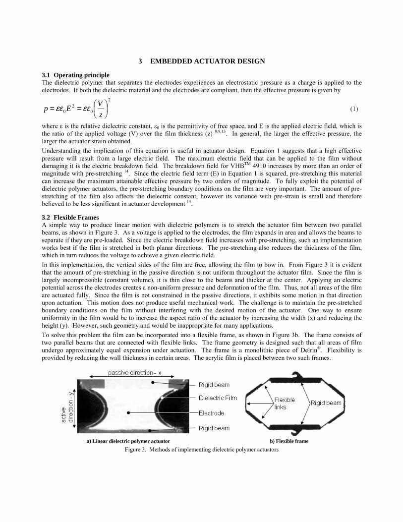
3 EMBEDDED ACTUATOR DESIGN
3.1 Operating principle The dielectric polymer that separates the electrodes experiences an electrostatic pressure as a charge is applied to the electrodes. If both the dielectric material and the electrodes are compliant, then the effective pressure is given by
2
02
0
==z
VEp εεεε (1)
where ε is the relative dielectric constant, ε0 is the permittivity of free space, and E is the applied electric field, which is the ratio of the applied voltage (V) over the film thickness (z) 8,9,13. In general, the larger the effective pressure, the larger the actuator strain obtained. Understanding the implication of this equation is useful in actuator design. Equation 1 suggests that a high effective pressure will result from a large electric field. The maximum electric field that can be applied to the film without damaging it is the electric breakdown field. The breakdown field for VHBTM 4910 increases by more than an order of magnitude with pre-stretching 14. Since the electric field term (E) in Equation 1 is squared, pre-stretching this material can increase the maximum attainable effective pressure by two orders of magnitude. To fully exploit the potential of dielectric polymer actuators, the pre-stretching boundary conditions on the film are very important. The amount of pre-stretching of the film also affects the dielectric constant, however its variance with pre-strain is small and therefore believed to be less significant in actuator development 14.
3.2 Flexible Frames A simple way to produce linear motion with dielectric polymers is to stretch the actuator film between two parallel beams, as shown in Figure 3. As a voltage is applied to the electrodes, the film expands in area and allows the beams to separate if they are pre-loaded. Since the electric breakdown field increases with pre-stretching, such an implementation works best if the film is stretched in both planar directions. The pre-stretching also reduces the thickness of the film, which in turn reduces the voltage to achieve a given electric field. In this implementation, the vertical sides of the film are free, allowing the film to bow in. From Figure 3 it is evident that the amount of pre-stretching in the passive direction is not uniform throughout the actuator film. Since the film is largely incompressible (constant volume), it is thin close to the beams and thicker at the center. Applying an electric potential across the electrodes creates a non-uniform pressure and deformation of the film. Thus, not all areas of the film are actuated fully. Since the film is not constrained in the passive directions, it exhibits some motion in that direction upon actuation. This motion does not produce useful mechanical work. The challenge is to maintain the pre-stretched boundary conditions on the film without interfering with the desired motion of the actuator. One way to ensure uniformity in the film would be to increase the aspect ratio of the actuator by increasing the width (x) and reducing the height (y). However, such geometry and would be inappropriate for many applications. To solve this problem the film can be incorporated into a flexible frame, as shown in Figure 3b. The frame consists of two parallel beams that are connected with flexible links. The frame geometry is designed such that all areas of film undergo approximately equal expansion under actuation. The frame is a monolithic piece of Delrin®. Flexibility is provided by reducing the wall thickness in certain areas. The acrylic film is placed between two such frames.
a) Linear dielectric polymer actuator b) Flexible frame
Figure 3. Methods of implementing dielectric polymer actuators

A second key function of the frame is that it provides an elastic restoring force that permits the actuator to work under both tension and compression. A welcome side-effect of the frame is that the risk of tearing of the film at its exposed edges is greatly reduced. The frame also prevents current arcs from developing around the edges of the film. Figure 4a shows an exploded view of the actuator module with the dielectric film integrated into its flexible frame. Higher actuation forces can be achieved by increasing the number of layers of film sandwiched between the frames. When using an even number of dielectric films, the electrodes can be arranged so that the two outer electrodes are both grounded. The high voltage is only present in the inside of the actuator and is thus shielded from the environment. The actuator discussed here uses two layers of the dielectric polymer as shown in Figure 4.
a) Exploded CAD representation b) Photograph
Figure 4. Embedded flexible-frame actuator module
3.3 Actuator performance and physical actuator model To evaluate the performance of the actuator, the force-displacement characteristics were measured, see Figure 5. Curves are shown for an actuator at 0kV, 5.5kV, and completing a work cycle. The work cycle is generated by constraining the displacement of the actuator. A voltage of 5.5kV is applied and the force applied to the constraint is recorded. While keeping the voltage fixed, the constraint is moved until the actuator force is zero. The voltage is then removed and the process is repeated. The area enclosed by a counter-clockwise work cycle corresponds to the work output per cycle 6.
13 14 15 16 17 18 19 20 21 22-3
-2
-1
0
1
2
3
4actuator force-displacement
length-y (mm)
forc
e (N
)
unchargedload line
chargedload line
work cycle
Figure 5. Actuator stiffness and work cycle

The slope of the curve, which corresponds to the stiffness of the actuator, is nearly constant at 0.5N/mm for the range shown. Some hysteresis is evident, which is attributed to the viscoelastic losses of the film and frame 9. As shown in Figure 5, changing the voltage from 0 to 5.5kV offsets the curve, but does not significantly change its slope, suggesting that the stiffness of the actuator is independent of the state of actuation over the range shown. The actuator can therefore be modeled as a spring that changes its undeformed length upon actuation while maintaining its stiffness, as shown in Figure 6a. The corresponding force-displacement curves are shown in Figure 6b.
a) Actuator model b) Work cycle
Figure 6. Idealized actuator model
In Figure 6b it can be seen that the vertical separation between the charged and uncharged stiffness curves represents the force differential the actuator can achieve if rigidly constrained. The horizontal separation of the curves at a given force corresponds to the actuator stroke, which is independent of external loading, provided the load remains constant throughout the stroke. Due to the compliance of the actuator, its length changes with external loading. The force generated by the actuator is not constant throughout the stroke. The force reaches its maximum at the beginning and linearly decreases to zero at the end of the stroke. However, for most applications including the BRAID, an actuator that provides uniform force is more desirable. Such actuator performance can be achieved by tuning the force displacement profiles in Figure 6b with a passive element.
3.4 Linear Bi-stable Elements Figure 7 shows a linear bi-stable element (LBE) and its corresponding force-displacement characteristics. The LBE consists of a base that elastically supports two opposing flexure arms. As a slightly oversized insert is placed between the arms, it pre-loads the base and causes the assembly to have two stable configurations. Between these bi-stable states, there is a region where the force-displacement curve is approximately linear and has a negative slope, as shown in Figure 7b. The slope is a function of the geometry and material of the LBE. By varying the width of the insert, the slope of the force-displacement curve in the near-linear region can be tuned precisely. The stiffness of the actuator and LBE in parallel is equivalent to the sum of the actuator stiffness and LBE stiffness. Thus, by designing a LBE with a slope of negative 0.5N/mm over its linear range, the combined actuator module can be tuned to have zero stiffness (constant force output) over an operating range.

12 14 16 18 20 22 24 26 28
-2.5
-2
-1.5
-1
-0.5
0
0.5
1
1.5
2LBE force-displacement
length-y (mm)
forc
e (N
)
approximatelinear range
a) photograph b) force-displacement profile
Figure 7. Linear bi-stable element
Figure 8a shows the force displacement characteristics of the combined actuator module including the passive element. The work cycle measurements presented Figure 5 were repeated. Figure 8a shows a range over which the actuator force is approximately constant. Comparing the work cycles in Figure 5 and Figure 8, the advantages of the compensated actuator become evident. The stroke of the actuator is increased from about 4mm to 8mm. By using mechanical stops the actuator motion can be confined to the zero-stiffness range. Such an actuator has uniform force-displacement characteristics and reaches the same endpoints regardless of loading, provided it is within actuator capability. Thus such an actuator module provides robust binary operation. By using the actuator in a binary fashion, the hysteresis introduced by the viscoelastic properties of the elastomer is no longer a concern. Figure 8b shows the displacement and current of the actuator versus time. Most of the current is drawn as the actuator charges. Some leakage current is drawn once the actuated state is reached. If the dielectric polymer actuator behaved as a true capacitor, there would be no current drawn at steady state. The actuator is switched off by draining the charge through a resistor. Theoretically, this energy could be recovered by circuitry and returned to an energy storage device such as a battery. While the voltage required for actuation is very high (5.5kV), the current drawn is extremely low. The peak current for the given actuator is about 0.03mA, which corresponds to a maximum electrical input of 0.165W.
12 14 16 18 20 22 24-2
-1.5
-1
-0.5
0
0.5
1
1.5
2compensated actuator work cycle
length-y (mm)
forc
e (N
)
range with nearly constant force
0 5 10 15 2010
15
20
25actuator displacement and current
time (s)
leng
th-y
(mm
)
0 5 10 15 20-0.02
0
0.02
0.04
time (s)
curre
nt (m
A)
a) work cycle b) displacement and current
Figure 8. Performance of compensated actuator module
Figure 9 shows the actuator in its two states. The actuation force is about 1.5N. The actuator stroke is about 8mm, with the polymer film undergoing a strain of about 57%. The mass of a complete actuator unit is approximately 6 grams.

Most of this mass is due to the frame and bi-stable element. For a double-layered actuator, the mass of the dielectric polymer and electrodes itself is less than 0.1 grams, only a fraction of what the actuator is capable of lifting.
Figure 9. Embedded flexible-frame actuator
The range of motion of the actuator could be further increased by developing passive elements that have the desired negative stiffness over a larger range. The stroke of the current prototype is limited by the range of the LBE, rather than by the film or frame.
4 BRAID PROTOTYPE When the actuators are implemented into the BRAID, they behave as structural elements with embedded actuation. Three parallel actuators form a single stage. A combination of identical stages forms the BRAID. The design goal of the BRAID is to produce a virtually all-plastic, lightweight, binary manipulator. Figure 10 shows a photograph of a single BRAID stage before the dielectric polymer actuators are integrated. The kinematics of the mechanism requires a revolute joint at the bottom of the actuator and a spherical joint at the top. One rotational DOF is provided by a cross-flexural hinge machined from Delrin®. The hinge at the top of the frame approximates a spherical joint for small motions. It consists of thin compliant leaf that connects two pointed stiff elements.
Figure 10. BRAID-skeleton without actuators
Figure 11 shows a 2-stage BRAID prototype manipulating a mirror. It has 6 binary DOF, allowing 26=64 discrete states. Each degree of freedom is controlled by a simple switch. The total mass of the 2 stage BRAID prototype is about 65grams. The mass of the active actuator material itself, i.e. the dielectric film and electrodes, accounts for only 1% of the total mass. This suggests that most of the weight savings could be achieved by optimizing the structure rather than the actuators themselves.

Figure 11. Photograph of a two-stage BRAID prototype
The performance of the BRAID presented here is sufficient to manipulate a small camera.
5 CONCLUSIONS Dielectric polymer artificial muscles have been introduced to the field of high-DOF binary robotics. The performance of these actuators shows promise of making high-DOF binary robotic systems practical. The current challenge with dielectric polymer actuators lies with effectively implementing them such that their full potential is exploited to perform mechanical work. Here, this challenge was addressed by embedding the polymer actuators into flexible frames which maintained the desired boundary conditions on the actuator film. By adding a passive element, a self-contained actuator module was formed that could work both under tension and compression and produced approximately uniform force throughout the stroke. The active actuator area achieves a relative strain of 57% and provides a force of 1.5N, while weighing 6 grams. The 2-stage BRAID prototype shows promise that these actuators are a feasible alternative to conventional technologies in the near future. The simplicity of the actuators allows for a BRAID design that is virtually all-plastic, inexpensive, lightweight, and easy to control. Research in this program is continuing to develop devices that fully exploit the dielectric polymer actuators in very high DOF practical binary systems.
6 ACKNOWLEDGEMENTS The support of the NASA Institute for Advanced Concepts (NIAC) for this research is acknowledged. The authors would like to thank Peter Weiss and Ebraheem Fontaine for their help in actuator development and fabrication of prototypes.
7 REFERENCES 1 G. Chirikjian, “A Binary Paradigm for Robotic Manipulators,” Proc. of IEEE International Conference on Robotics
and Automation, Vol. 4, pp. 3063-3069, 1994. 2 D. Lees, G. Chirikjian, “A Combinatorial Approach to Trajectory Planning for Binary Manipulators,” Proc. of the
IEEE International Conf. on Robotics and Automation, Minneapolis, MN, 1996. 3 M. Lichter, V. Sujan, S. Dubowsky, “Computational Issues in the Planning and Kinematics of Binary Robots,” 2002
IEEE International Conference on Robotics and Automation, Washington D.C., 2002. 4 M. Hafez, M. Lichter, S. Dubowsky, “Optimized Binary Modular Reconfigurable Robotic Devices,” 2002 IEEE
International Conference on Robotics and Automation, Washington, D.C., May 11-15, 2002. 5 R. Pelrine, P. Sommer-Larsen, R. Konrbluh, R. Heydt, G. Kofod, Q. Pei, P. Gravesen, “Applications of Dielectric
Elastomer Actuators,” in Smart Structures and Materials 2001: Electroactive Polymer Actuators and Devices, Yoseph Bar-Cohen, Editor, Proceedings of SPIE Vol. 4329, March 2001.
6 K. Maejer, M. Rosenthal, R. Full, “Muscle-like actuators? A comparison between three electroactive polymers,” Smart Structrues and Materials 2001: Electroactive Polymer Actuators and Deevices, Yoseph Bar-Cohen, Editor, Proceedings of SPIE Vol. 4329, pp. 7-15, March 2001.

7 V. Sujan, M. Lichter, S. Dubowsky, “Lightweight Hyper-redundant Binary Elements for Planetary Exploration Robots,” Proc. 2001 IEEE/ASME International Conference on Advanced Intelligent Mechatronics (AIM '01) 811, Como, Italy, July 2001.
8 R. Kornbluh, R. Pelrine, J. Joseph, R. Heydt, Q Pei, S. Chiba, “High-field electrostriction of elastomeric polymer dielectics for actuation,” in Smart Structures and Materials 1999: Electroactive Polymer Actuators and Devices, Yoseph Bar-Cohen, Editor, Proceedings of SPIE Vol. 3669, pp. 149-161, 1999.
9 R. Pelrine, R. Kornblu, Q. Pei, J. Joseph, “High Speed Electrically Actuated Elastomers with Strain Greater Than 100%,” Science, Vol. 287, pp. 836-839, 2000.
10 R. Pelrine, R. Kornbluh, J. Eckerle, P. Jeuck, S. Oh, Q. Pei, S. Stanford, “Dielectric Elastomers: Generator Mode Fundamentals and Applications,” in Smart Structures and Materials 2001: Electroactive Polymer Actuators and Devices, Yoseph Bar-Cohen, Editor, Proceedings of SPIE Vol. 4329, pp.148-156, March 2001.
11 S. Cho, S. Ryew, J. Jeon, H. Kim, J. Nam, H. Choi, and K. Tanie, "Electrostrictive Polymer Actuator Using Elastic Restoring Force," Proceedings of 1st Intelligent Microsystem Symposium, pp. 1963-1968, 2001.
12 J. Eckerle, S. Stanford, J. Marlow, J. Marlow, R. Schmidt, S. Oh, T. Low, S. Shastri “A Biologically Inspired hexapedal Robot Using Field-Effect Electroactive Elastomer Artificial Muscles,” in Smart Structures and Materials 2001: Electroactive Polymer Actuators and Devices, Yoseph Bar-Cohen, Editor, Proceedings of SPIE Vol. 4329, March 2001.
13 R. Pelrine, R. Konrbluh, J. Joseph, “Electrostriction of polymer dielectrics with compliant electrodes as a means of actuations,” Sensor and Actuators A: Physical 64, pp. 77-85.
14 G. Kofod, R. Kornbluh, R. Pelrine, P. Sommer-Larsen, “Actuation response of polyacrylate dielectric elastomers,” in Smart Structures and Materials 2001: Electroactive Polymer Actuators and Devices, Yoseph Bar-Cohen, Editor, Proceedings of SPIE Vol. 4329, p141-147, March 2001.
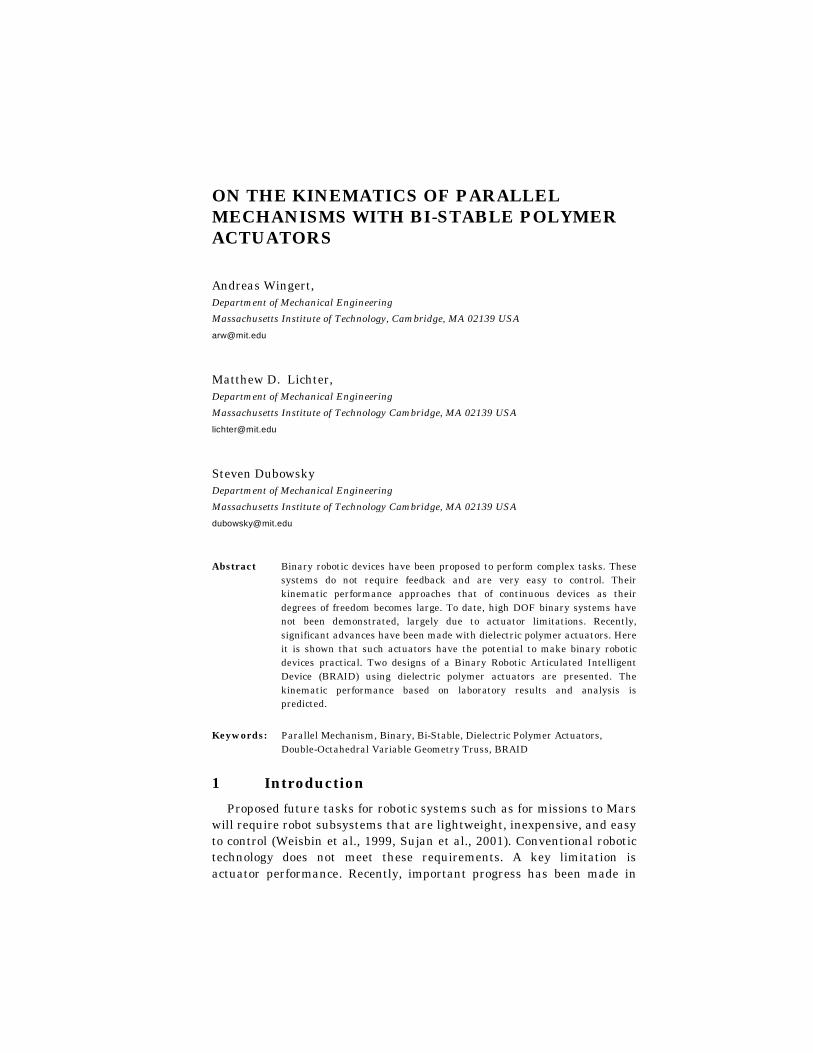
ON THE KINEMATICS OF PARALLEL MECHANISMS WITH BI-STABLE POLYMER ACTUATORS
Andreas Wingert, Department of Mechanical Engineering
Massachusetts Institute of Technology, Cambridge, MA 02139 USA
Matthew D. Lichter, Department of Mechanical Engineering
Massachusetts Institute of Technology Cambridge, MA 02139 USA
Steven Dubowsky Department of Mechanical Engineering
Massachusetts Institute of Technology Cambridge, MA 02139 USA
Abstract Binary robotic devices have been proposed to perform complex tasks. These systems do not require feedback and are very easy to control. Their kinematic performance approaches that of continuous devices as their degrees of freedom becomes large. To date, high DOF binary systems have not been demonstrated, largely due to actuator limitations. Recently, significant advances have been made with dielectric polymer actuators. Here it is shown that such actuators have the potential to make binary robotic devices practical. Two designs of a Binary Robotic Articulated Intelligent Device (BRAID) using dielectric polymer actuators are presented. The kinematic performance based on laboratory results and analysis is predicted.
Keywords: Parallel Mechanism, Binary, Bi-Stable, Dielectric Polymer Actuators, Double-Octahedral Variable Geometry Truss, BRAID
1 Introduction
Proposed future tasks for robotic systems such as for missions to Mars will require robot subsystems that are lightweight, inexpensive, and easy to control (Weisbin et al., 1999, Sujan et al., 2001). Conventional robotic technology does not meet these requirements. A key limitation is actuator performance. Recently, important progress has been made in

two areas that have the potential to meet this challenge. The first is hyper redundant binary robotic devices, and the second is dielectric polymer actuators (Pelrine et al., 2001). Here these two technologies are brought together in a concept called BRAID – Binary Robotic Articulated Intelligent Device. The BRAID is a lightweight, hyper-redundant binary manipulator with a large number of embedded actuators (Sujan et al. 2001). The kinematic performance is predicted based on measured results of actuator prototypes. Performance is also shown for projected performance of these actuators. Analysis suggests that dielectric polymer actuators have the potential of overcoming current actuator limitations and serving as a key component for high degree of freedom binary element manipulators. Such systems have the potential to be important in future robotic systems
2 Background and Literature
In the 1960’s and 70’s the concept of binary and sensorless robotics was introduced (Anderson et al., 1967, Roth et al., 1973). More recently increased computation power made the analysis, control, and planning for binary robots feasible (Chirikjian, 1994, Lees et al., 1996). Some experimental work has been done on binary redundant manipulators (Chirikjian, 1994). An example is a large variable geometry truss (VGT) manipulator that was constructed using pneumatic actuators. This implementation, while acceptable for systems with few DOF, cannot readily be extended to develop practical systems with very large DOF. To date, little work has been done to develop simple, lightweight, robust binary design concepts.
Development of dielectric polymer actuators started in the late 1990s (Pelrine et al., 1997). These actuators are one of a large class of electro active polymers (EAP) that has been studied (Madden et al., 2000). Recent progress has resulted from the identification of new and more effective dielectric materials, making it one of the most promising new actuator technologies, with relative strains of up to 380% having been reported (Pelrine et al., 2000, Pelrine et al., 2001). Applications such as robots, acoustic speakers, and solid-state optical devices have been proposed, including a snake-like manipulator using a small number antagonistic pairs of dielectric polymers, controlled in a conventional analog fashion (Pelrine et al., 2001).
To date, very high DOF binary robotic systems implemented with polymer actuators have yet to be explored. This is the subject of this paper. The focus is on the expected system kinematic performance given the demonstrated and anticipated actuator performances.
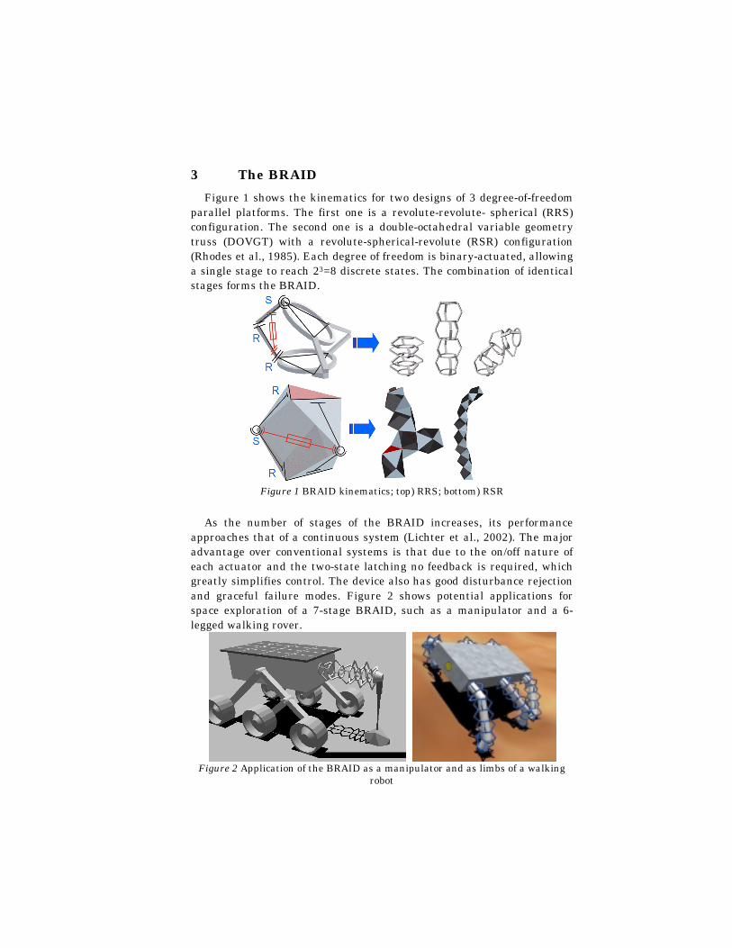
3 The BRAID
Figure 1 shows the kinematics for two designs of 3 degree-of-freedom parallel platforms. The first one is a revolute-revolute- spherical (RRS) configuration. The second one is a double-octahedral variable geometry truss (DOVGT) with a revolute-spherical-revolute (RSR) configuration (Rhodes et al., 1985). Each degree of freedom is binary-actuated, allowing a single stage to reach 23=8 discrete states. The combination of identical stages forms the BRAID.
Figure 1 BRAID kinematics; top) RRS; bottom) RSR
As the number of stages of the BRAID increases, its performance approaches that of a continuous system (Lichter et al., 2002). The major advantage over conventional systems is that due to the on/off nature of each actuator and the two-state latching no feedback is required, which greatly simplifies control. The device also has good disturbance rejection and graceful failure modes. Figure 2 shows potential applications for space exploration of a 7-stage BRAID, such as a manipulator and a 6-legged walking rover.
Figure 2 Application of the BRAID as a manipulator and as limbs of a walking
robot
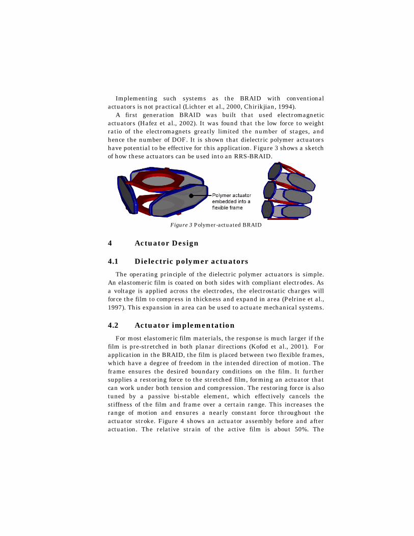
Implementing such systems as the BRAID with conventional actuators is not practical (Lichter et al., 2000, Chirikjian, 1994).
A first generation BRAID was built that used electromagnetic actuators (Hafez et al., 2002). It was found that the low force to weight ratio of the electromagnets greatly limited the number of stages, and hence the number of DOF. It is shown that dielectric polymer actuators have potential to be effective for this application. Figure 3 shows a sketch of how these actuators can be used into an RRS-BRAID.
Figure 3 Polymer-actuated BRAID
4 Actuator Design
4.1 Dielectric polymer actuators
The operating principle of the dielectric polymer actuators is simple. An elastomeric film is coated on both sides with compliant electrodes. As a voltage is applied across the electrodes, the electrostatic charges will force the film to compress in thickness and expand in area (Pelrine et al., 1997). This expansion in area can be used to actuate mechanical systems.
4.2 Actuator implementation
For most elastomeric film materials, the response is much larger if the film is pre-stretched in both planar directions (Kofod et al., 2001). For application in the BRAID, the film is placed between two flexible frames, which have a degree of freedom in the intended direction of motion. The frame ensures the desired boundary conditions on the film. It further supplies a restoring force to the stretched film, forming an actuator that can work under both tension and compression. The restoring force is also tuned by a passive bi-stable element, which effectively cancels the stiffness of the film and frame over a certain range. This increases the range of motion and ensures a nearly constant force throughout the actuator stroke. Figure 4 shows an actuator assembly before and after actuation. The relative strain of the active film is about 50%. The

actuator assemblies serve both as actuator and structural components when integrated into the RRS-BRAID (Figure 3).
Figure 4 Photograph of embedded polymer actuator before and after actuation
4.3 Actuator Performance
The actuation forces are proportional to the cross sectional area of the film and can therefore be increased by combining multiple layers of the actuator material. Since a single layer of stretched dielectric material is only about 50µm thick, adding additional layers increases the actuation forces without significantly changing the geometry of the actuator. For an actuator with the same geometry shown in Figure 4, the actuation force is about 0.75N per layer.
The mass of a complete actuator unit is approximately 8 grams. Most of this mass is due to the frame and bi-stable element. For a double-layer actuator, the mass of the dielectric polymer actuator itself is less than 0.1 grams, only a fraction of what the actuator is capable of lifting. The performance of the actuator material is also independent of scale. In contrast to voice-coil actuators, which have poor performance on small scales, these actuators lend themselves for miniaturization (Pelrine et al., 2001). This suggests that the proposed BRAID can find applications on the micro- scale.
The actuator requires high voltage (5kV), but only draws currents of about 50µA, hence they can be powered by conventional miniature batteries. New thinner films will result in lower voltages.
5 BRAID Kinematics and Workspace
To illustrate the current and predicted capabilities of a dielectric polymer powered BRAID, a 4-stage (12 DOF) device is considered. The workspace is a function of the geometry of the individual stages as well as the strokes of the actuators.
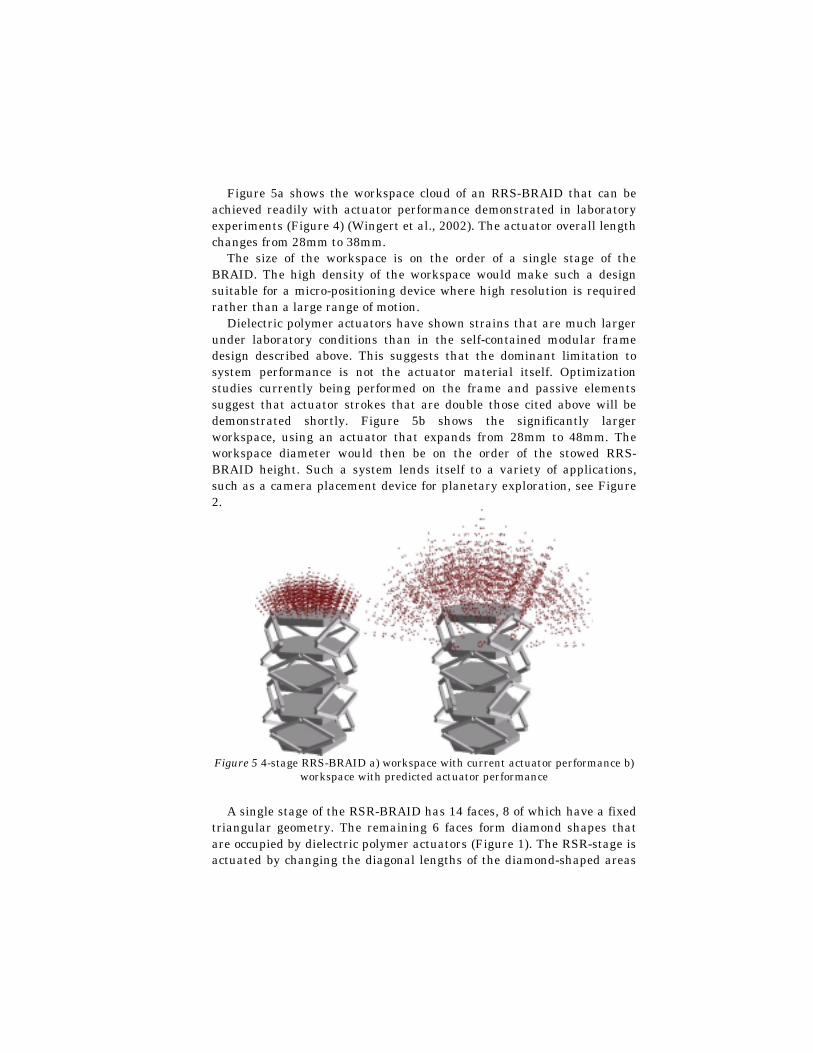
Figure 5a shows the workspace cloud of an RRS-BRAID that can be achieved readily with actuator performance demonstrated in laboratory experiments (Figure 4) (Wingert et al., 2002). The actuator overall length changes from 28mm to 38mm.
The size of the workspace is on the order of a single stage of the BRAID. The high density of the workspace would make such a design suitable for a micro-positioning device where high resolution is required rather than a large range of motion.
Dielectric polymer actuators have shown strains that are much larger under laboratory conditions than in the self-contained modular frame design described above. This suggests that the dominant limitation to system performance is not the actuator material itself. Optimization studies currently being performed on the frame and passive elements suggest that actuator strokes that are double those cited above will be demonstrated shortly. Figure 5b shows the significantly larger workspace, using an actuator that expands from 28mm to 48mm. The workspace diameter would then be on the order of the stowed RRS-BRAID height. Such a system lends itself to a variety of applications, such as a camera placement device for planetary exploration, see Figure 2.
Figure 5 4-stage RRS-BRAID a) workspace with current actuator performance b)
workspace with predicted actuator performance
A single stage of the RSR-BRAID has 14 faces, 8 of which have a fixed triangular geometry. The remaining 6 faces form diamond shapes that are occupied by dielectric polymer actuators (Figure 1). The RSR-stage is actuated by changing the diagonal lengths of the diamond-shaped areas

with the dielectric polymer. Actuators enclosed in a diamond-shaped frame have been successfully demonstrated.
One advantage of the RSR-BRAID over the RRS-BRAID is that the actuators are directly integrated into the structure, reducing the number of components. This comes at the cost of adding some complexity to the design process, as actuators and structure can no longer be tuned independently. The joints of the RSR-BRAID could be designed to provide the desired restoring forces. As with the previous design, the actuation forces can easily be increased by adding layers of actuator film.
Taking the currently achieved performance of the frame actuators and applying them to the RSR-BRAID results in a workspace shown in Figure 6a. If the effective motion of each actuator were to be doubled, a significantly larger workspace would be achieved (Figure 6b).
Figure 6 4-stage RSR - BRAID workspace cloud a) with current actuator
performance b) with predicted actuator performance
6 Conclusion
It has been shown that dielectric polymer actuators have the potential of overcoming the key limitations of traditional actuators in making high-degree of freedom binary parallel robots practical. The simplicity of the actuators allows for a BRAID design that is virtually all-plastic, inexpensive, lightweight, and easy to control. Research in this program is continuing to develop devices that fully exploit the dielectric polymer actuators in very high DOF practical binary systems.
7 Acknowledgements
The support of the NASA Institute for Advanced Concepts (NIAC) for this research is acknowledged.
8 References
Anderson, V., Horn, R. (1967) Tensor Arm Manipulator Design. ASME paper, 67-DE-57
Chirikjian, G. (1994) A Binary Paradigm for Robotic Manipulators, Proc. of IEEE International Conference on Robotics and Automation, Vol. 4, pp. 3063-3069
Hafez, M., Lichter, M., Dubowsky, S. (2002) Optimized Binary Modular Reconfigurable Robotic Devices, IEEE International Conf. on Robotics and Automation. Washington, D.C.
Kofod, G., Kornbluh, R., Pelrine, R., Sommer-Larsen, P. (2001) Actuation response of polyacrylate dielectric elastomers, Proc. of SPIE Vol. 4329, pp. 141-147
Lees D., Chirikjian, G. (1996) A Combinatorial Approach to Trajectory Planning for Binary Manipulators, Proc. of the IEEE International Conf. on Robotics and Automation, Minneapolis, Mn
Lichter, M., Sujan, V., Dubowsky, S. (2000) Experimental Demonstrations for a New Paradigm in Space Robotics, Proc. of the Seventh International Symposium on Experimental Robotics, ISER ‘00. Hawaii, pp. 225-234.
Lichter, M., Sujan, V., Dubowsky, S., (2002) Computational Issues in the Planning and Kinematics of Binary Robots, ICRA, Washington D.C.
Madden, J., Cush, R., Kanigan, T., et al. (2000) Fast-contracting Polypyrrole Actuators, Synthetic Metals, 113: pp.185-193
Pelrine, R., Kornbluh, R., Joseph, J., Chiba S.,. (1997) Electrostriction of Polymer Films for Microactuators, Proc. IEEE Tenth Annual International Workshop on Micro Electro mechanical Systems, Nagoya, Japan, pp. 238-243
Pelrine, R., Kornblu, R., Pei, Q., Joseph, J. (2000) High Speed Electrically Actuated Elastomers with Strain Greater Than 100%, Science, Vol. 287, pp. 836-839
Pelrine, R., Sommer-Larsen, P., Konrbluh, R., Heydt, R., Kofod, G. Pei, P. Gravesen, Q. (2001) Applications of Dielectric Elastomer Actuators, Proc. of SPIE Vol. 4329
Rhodes, M., Mikulas M., Jr,. (1985) Deployable Controllable Geometry Truss Beam, NASA Technical Memorandum.
Roth, B., Rastegar, J., Scheinman, V. (1973) On the Design of Computer Controlled Manipulators, First CISM-IFTMM Symposium on Theory and Practice of Robots and Manipulators, pp. 93-113
Sujan, V., Lichter, M., Dubowsky, S., (2001) Lightweight Hyper-redundant Binary Elements for Planetary Exploration Robots, Proc. IEEE/ASME Int. Conf. on Advanced Intelligent Mechatronics, July 2001, Como, Italy.
Weisbin, C., Rodriguez, G., Schenker, P., et al (1999) Autonomous Rover Technology for Mars Sample Return, International Symposium on Artificial Intelligence, Robotics and Automation in Space (i-SAIRAS'99), 1-10.
Wingert, A., Lichter, M., Hafez, M., Dubowsky, S. (2002) Plastic Hyper Redundant Robot Manipulators Actuated by Optimized Binary Electrostrictive Polymers, SPIE Vol. 4695, San Diego.