massey ferguson gc1700 series installation & owner’s...
TRANSCRIPT

Page 1 of 20
I
NS
TALL
AT
ION
& O
WN
ER
’S M
AN
UA
L
Rev. B, 8/14/2015
IMPORTANT: If installing snow blower accessory with cab installed, electric chute control must be utilized. The contents of this envelope are the property of the owner. Leave with the owner when installation is complete.
Massey Ferguson GC1700 Series All Steel Cab p/n: 1MFGC1700AS1 Soft Side Cab p/n: 1MFGC1700SS1
Fits Tractor Models: GC1705, GC1710, GC1715, GC1720
APPROXIMATE INSTALLATION TIME: 2 to 3 HOURS (Not including accessories)
All Steel Cab Shown with Optional Front Work Lights.
Available Options: 1. Front LED Work Lights (P/N: 9LEDW4) 2. Rear LED Work Lights (P/N: 9LEDW3) 3. Rear Wiper (P/N: 9PWK85F) - Not available for soft side cab. 4. Strobe Light (P/N: 9LEDS2) 5. Heater (P/N: 9PH20S54)
Note: Front wiper (P/N: 9PWK110) comes standard with cab kit.
p/n: IM-1MFGC1700-1
Page 2 of 20
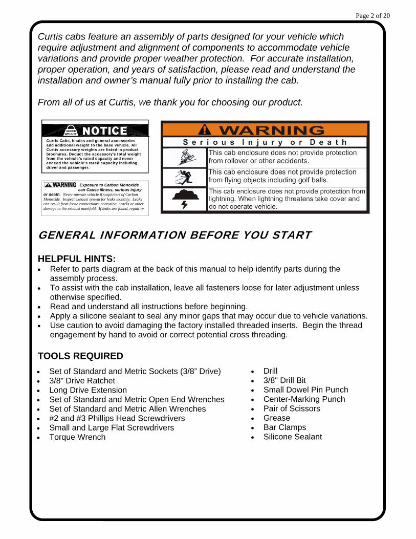
Curtis cabs feature an assembly of parts designed for your vehicle which require adjustment and alignment of components to accommodate vehicle variations and provide proper weather protection. For accurate installation, proper operation, and years of satisfaction, please read and understand the installation and owner’s manual fully prior to installing the cab. From all of us at Curtis, we thank you for choosing our product.
GENERAL INFORMATION BEFORE YOU START HELPFUL HINTS: Refer to parts diagram at the back of this manual to help identify parts during the
assembly process. To assist with the cab installation, leave all fasteners loose for later adjustment unless
otherwise specified. Read and understand all instructions before beginning. Apply a silicone sealant to seal any minor gaps that may occur due to vehicle variations. Use caution to avoid damaging the factory installed threaded inserts. Begin the thread
engagement by hand to avoid or correct potential cross threading. TOOLS REQUIRED
driver and passenger.
Curtis accessory weights are listed in product add additional weight to the base vehicle. All Curtis Cabs, blades and general accessories
ADDEDWEIGHT
brochures. Deduct the accessory's total weight from the vehicle's rated capacity and never exceed the vehicle's rated capacity including
Exposure to Carbon Monoxide can Cause illness, serious injury
or death. Never operate vehicle if suspicious of Carbon Monoxide. Inspect exhaust system for leaks monthly. Leaks can result from loose connections, corrosion, cracks or other damage to the exhaust manifold. If leaks are found, repair or
Set of Standard and Metric Sockets (3/8” Drive) 3/8” Drive Ratchet Long Drive Extension Set of Standard and Metric Open End Wrenches Set of Standard and Metric Allen Wrenches #2 and #3 Phillips Head Screwdrivers Small and Large Flat Screwdrivers Torque Wrench
Drill 3/8" Drill Bit Small Dowel Pin Punch Center-Marking Punch Pair of Scissors Grease Bar Clamps Silicone Sealant
Page 3 of 20
STEP 1: (VEHICLE PREP)
1.1 Remove the following items from the vehicle: SMV (Slow Moving Vehicle) sign and bracket
(GC1710 & GC1720). Save for reuse. (2) Rear signal lights. Save for reuse. Disconnect
wires under fender and pull out of the ROPS tube (Roll-Over Protective Structure). Save the M8 screws for reuse.
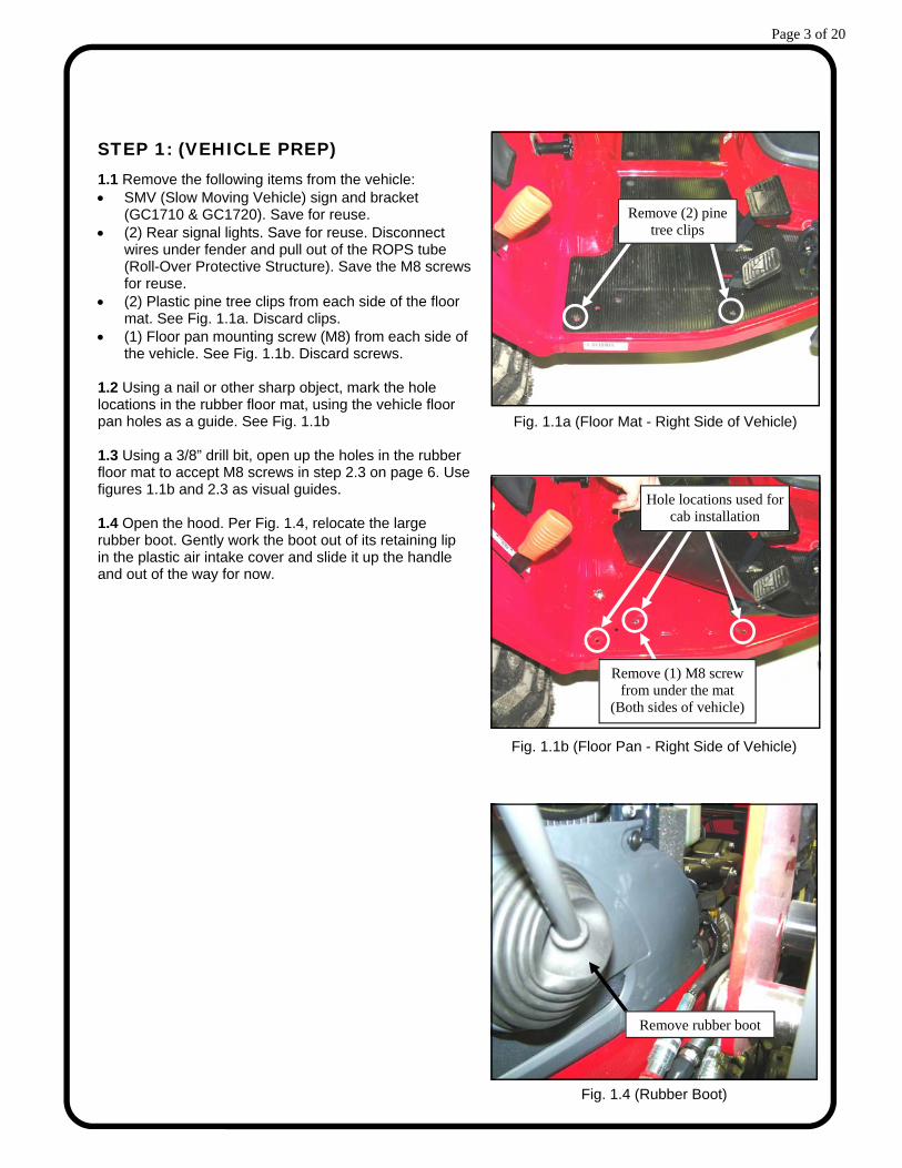
(2) Plastic pine tree clips from each side of the floor mat. See Fig. 1.1a. Discard clips.
(1) Floor pan mounting screw (M8) from each side of the vehicle. See Fig. 1.1b. Discard screws.
1.2 Using a nail or other sharp object, mark the hole locations in the rubber floor mat, using the vehicle floor pan holes as a guide. See Fig. 1.1b 1.3 Using a 3/8” drill bit, open up the holes in the rubber floor mat to accept M8 screws in step 2.3 on page 6. Use figures 1.1b and 2.3 as visual guides. 1.4 Open the hood. Per Fig. 1.4, relocate the large rubber boot. Gently work the boot out of its retaining lip in the plastic air intake cover and slide it up the handle and out of the way for now.
Fig. 1.1a (Floor Mat - Right Side of Vehicle)
Remove (2) pine tree clips
Remove (1) M8 screw from under the mat
(Both sides of vehicle)
Fig. 1.1b (Floor Pan - Right Side of Vehicle)
Hole locations used for cab installation
Fig. 1.4 (Rubber Boot)
Remove rubber boot
Page 4 of 20
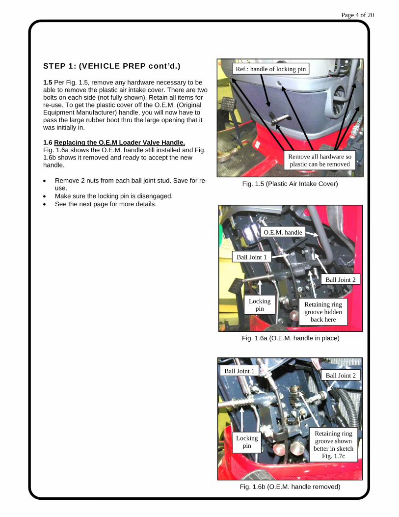
STEP 1: (VEHICLE PREP cont’d.) 1.5 Per Fig. 1.5, remove any hardware necessary to be able to remove the plastic air intake cover. There are two bolts on each side (not fully shown). Retain all items for re-use. To get the plastic cover off the O.E.M. (Original Equipment Manufacturer) handle, you will now have to pass the large rubber boot thru the large opening that it was initially in. 1.6 Replacing the O.E.M Loader Valve Handle. Fig. 1.6a shows the O.E.M. handle still installed and Fig. 1.6b shows it removed and ready to accept the new handle. Remove 2 nuts from each ball joint stud. Save for re-
use. Make sure the locking pin is disengaged. See the next page for more details.
Fig. 1.5 (Plastic Air Intake Cover)
Remove all hardware so plastic can be removed
Fig. 1.6b (O.E.M. handle removed)
Ball Joint 2
Retaining ring groove shown better in sketch
Fig. 1.7c
Ball Joint 1
Locking pin
Fig. 1.6a (O.E.M. handle in place)
O.E.M. handle
Locking pin
Ball Joint 1
Ball Joint 2
Ref.: handle of locking pin
Retaining ring groove hidden
back here

Page 5 of 20
STEP 1: (VEHICLE PREP cont’d.) 1.7 See Fig. 1.7. A dowel pin must be partially removed in order to remove the O.E.M. handle. The dowel pin is underneath a thin wire retaining ring (WRR) shown in figures 1.7a and 1.7b. Fig. 1.7c shows section views of before, during, and after the swap out. Note: the small shaded-in circle represents the WRR. It is suggested to work the WRR up onto the
shoulder as shown rather than removing it completely. Do not remove the retaining ring holding the small rubber boot.
With a small, flat screwdriver or pick tool, pry the WRR out of the retaining groove on the mating part.
Once the screwdriver is under the WRR, you can work it around and out of the groove with your fingers. Do not over-stretch or extend the wire. It must be re-installed snugly back in the groove when done.
With a small drive pin, knock the dowel out just enough to be able to lift out the welded post as shown in the middle illustration below.
Remove the O.E.M handle and install the replacement handle (grease where shown in Fig– ure 1.7).
For assistance, engage the handle locking pin then install the dowel fully thru the new handle using the wide face of a large flat screwdriver. Finish by using the narrow edge of the same screwdriver to push the end of the dowel flush with the bottom of the WRR groove.
Install the WRR so it’s fully seated in the bottom of the groove on all sides.
Fig. 1.7a (WRR)
Fig. 1.7 (New replacement handle)
hole for dowel pin
Grease O.D.
of post
Grease I.D. of sleeve
Fig. 1.7c (section view of steps to be taken)
WRR temporarily placed up here
O.E.M. handle removed
Replacement handle installed
Fig. 1.7b (WRR)
remove this top retaining ring
Boot retaining ring (do not remove)
Small rubber boot (do not remove)
dowel under WRR
Partially remove dowel
Reinstall dowel

Page 6 of 20
STEP 1: (VEHICLE PREP cont’d.) 1.8 With the locking pin still engaged, re-install the O.E.M. nuts (2 per) onto both ball joint studs. 1.9 Per Fig. 1.9, re-install the plastic air intake cover and all the associated O.E.M. hardware. 1.10 Per Fig. 1.10, the O.E.M. (Original Equipment Manufacturer) rubber knob is to be removed by being cut off or heating up the pipe which will weaken the glue and the knob can then be twisted and pulled off. Discard the rubber knob. Note: the new rubber knob is threaded/removable. 1.11 Remove the rubber boot from the old handle and re-install it on the new replacement handle and back into the receiving hole in the plastic air intake cover. Thread the new rubber knob onto the end of the new loader valve handle. STEP 2: (SIDE FRAMES)
Note: For ease of handling, the gas shocks and doors can be temporarily removed from the side frames. 2.1 Place the cowl over the vehicle hood in preparation for the side frames. See Fig. 3.1 on the next page for orientation and reference. 2.2 Remove the factory installed nut and washer from the outer front ROPS mounting stud (both sides). See Fig. 2.2 Install the side frame as shown. Re-install the washer and nut. Leave finger tight. 2.3 Fasten side frames to vehicle floor pan. See Fig. 2.3. Leave fasteners finger tight. Note: middle screws go into factory weld nuts on vehicle. Hardware Used Qty M8 Button Head Cap Screws (BHCS) 6 M8 Fender Washers 6 M8 Flange Nut 4
Fig. 2.3 (Cab Floor Board Installation)
Fender washers and heads of screws up top
Fig. 2.2 (Side Frame Bracket Installation)
Remove and re-install O.E.M. nut and washer
Fig. 1.9 (Plastic Air Intake Cover)
Re-install all hardware
Fig. 1.10 (Rubber Knob)
Ref.: handle of locking pin

Page 7 of 20
STEP 3: (COWL)
3.1 Fasten the cowl to the side frames as shown in Fig– ure 3.1. The bulb rubber in the center should lay across the dashboard and flex inwards towards the steering wheel. Fasten to the factory installed threaded inserts in each side frame. Starting from the top, install all fasteners finger tight. Next, tighten lower (6) screws first and then tighten upper (2) screws. Hardware Used Qty 5/16-18 Flange Head Cap Screw (FHCS) 8
STEP 4: (WINDSHIELD SUPPORT)
4.1 Install windshield support. See Fig. 4.1 & 4.2. Tighten at this time. Hardware Used Qty 1/4-20 Truss Head Screws 4 1/4-20 Flange Nut 4 4.2. Install left side roof hinge pin as shown in Fig 4.2. Snug up the bolts. Note: The left roof hinge pin will be installed during roof installation at step 12. Hardware Used Qty 1/4-20 FHCS 2 1/4-20 Flange Nut 2
STEP 5: (RADIATOR SHROUD)
5.1 Install the radiator shroud as shown. Position shroud so that shroud contours follow cowl contours. Tighten. Hardware Used Qty 5/16-18 FHCS 4 5/16-18 Flange Nut 4
Fig. 3.1 (Cowl Installation - Tractor not shown for clarity)
Fig. 5.1 (Radiator Shroud Installation) Fig. 4.2 (Roof Hinge Installation)
Tighten Last
Fig. 4.1 (Windshield Support Installation)

Page 8 of 20
STEP 6: (ROLL BAR BRACKETS)
6.1 Per Fig. 6.1, select the appropriate pair of roll bar brackets for the application. Discard whichever pair is not used. For GC1705 / GC1715 model tractors:
If installing on a GC1710 or GC1720 tractor, proceed to step 6.3 6.2 Install the left ROPS bracket to the fixed ROPS as shown. Repeat on the right side. Tighten all hardware. See Fig. 6.2 Hardware Used Qty M8 X 65mm Long FHCS 4 (Removed from vehicle in step 1) M8 Flange Nut 4 For GC1710 / GC1720 model tractors:
If installing on a GC1705 or GC1715 tractor, proceed to step 6.4. 6.3 Install the left ROPS bracket to the folding ROPS as shown. Repeat on the right side. Tighten all hardware. See Fig. 6.3 Hardware Used Qty M8 X 65mm Long FHCS 4 (Removed from vehicle in step 1) M8 Flange Nut 4 All Tractor Models:
6.4 Reinstall Vehicle lights to open position on ROPS brackets. See Fig. 6.2 or 6.3, depending on vehicle model. Feed wire down through ROPS and reconnect under vehicle fender. Hardware Used Qty M8 Button Head Cap Screw 4 IMPORTANT: The rear light wiring must be routed through the ROPS tubes before installing the Rear Legs.
Fig. 6.1 (Roll Bar Bracket Options)
For use on folding ROPS (GC1710 & GC1720)
For use on fixed ROPS (GC1705 & GC1715)
Fig. 6.3 (GC1710 & GC1720 Only)
Fig. 6.2 (GC1705 & GC1715 Only)
R R
L L
Page 9 of 20
FOR TRACTOR MODELS GC1705 AND GC1715 INSTALLATIONS:
Note: If installing cab onto GC1710 or GC1720 tractor model, skip to step 9 at this time. STEP 7: (HARD REAR PANEL)
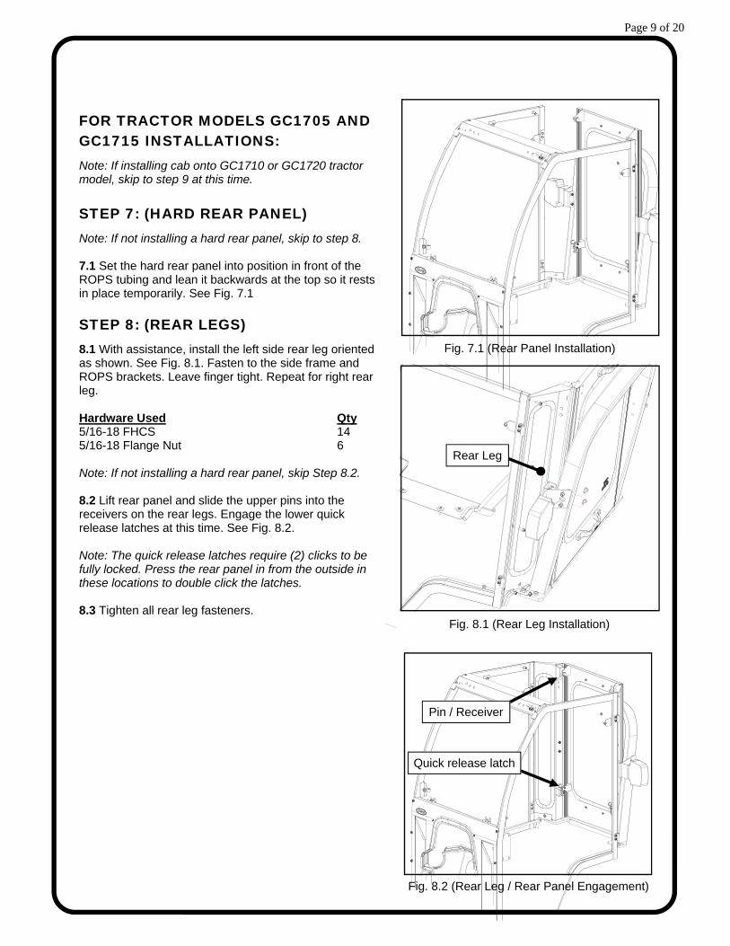
Note: If not installing a hard rear panel, skip to step 8. 7.1 Set the hard rear panel into position in front of the ROPS tubing and lean it backwards at the top so it rests in place temporarily. See Fig. 7.1
STEP 8: (REAR LEGS)
8.1 With assistance, install the left side rear leg oriented as shown. See Fig. 8.1. Fasten to the side frame and ROPS brackets. Leave finger tight. Repeat for right rear leg. Hardware Used Qty 5/16-18 FHCS 14 5/16-18 Flange Nut 6 Note: If not installing a hard rear panel, skip Step 8.2. 8.2 Lift rear panel and slide the upper pins into the receivers on the rear legs. Engage the lower quick release latches at this time. See Fig. 8.2. Note: The quick release latches require (2) clicks to be fully locked. Press the rear panel in from the outside in these locations to double click the latches. 8.3 Tighten all rear leg fasteners.
Fig. 7.1 (Rear Panel Installation)
Fig. 8.1 (Rear Leg Installation)
Fig. 8.2 (Rear Leg / Rear Panel Engagement)
Rear Leg
Pin / Receiver
Quick release latch

Page 10 of 20
FOR TRACTOR MODELS GC1710 AND GC1720 INSTALLATIONS:
Note: If installing cab onto GC1705 or GC1715 tractor model, skip to step 11 at this time.
STEP 9: (REAR LEGS)
9.1 Install the left side rear leg oriented as shown. Fasten to the side frame and ROPS bracket. See Fig. 9.1. Tighten all fasteners. Repeat for right rear leg. Hardware Used Qty 5/16-18 FHCS 14 5/16-18 Flange Nut 6
STEP 10: (HARD REAR PANEL)
Note: If not installing a hard rear panel, skip to step 11. 10.1 Lift rear panel and insert the upper pins into the receivers on the rear legs. Engage the lower quick release latches at this time. See Fig. 10.1. Note: The quick release latches require (2) clicks to be fully locked. Press the rear panel in from the outside in these locations to double click the latches.
Fig. 10.1 (Rear Panel Installation)
Fig. 9.1 (Rear Leg Installation)
Rear Leg
Quick release latch
Pin / Receiver

Page 11 of 20
STEP 11: (WINDSHIELD)
11.1 Install the windshield to the windshield support using (1) plastic spacer block underneath each upper plastic hinge to space it off the windshield support. Snug fasteners, but do not tighten fully. See Fig. 11.1. Hardware Used Qty 5/16-18 X 1-1/2” Long Flat Head Screws 4 5/16-18 Flange Nut 4 Plastic Spacer Blocks 2 11.2 Compress the spring loaded tabs on the pop-out windshield latches and engage the plastic pins into the receiver tabs mounted to the top of the cowl. Close pop-out latches. 11.3 Tighten windshield fasteners. Caution: The windshield hinges are plastic components. Do not over tighten the 5/16-18 flat head screws. Torque to 7 ft.-lbs. max. STEP 12: (ROOF)
12.1 With assistance, lift the roof onto the side frames. See Figure 12.1. Take care not to engage the quick release latches with the side frame latch pins.
Move the roof into position, such that the previously installed hinge pin mates with the factory installed sleeve on the roof. Note: It may be necessary to loosen the hinge pin fasteners installed in Step 4.2. Move the rear section of the roof into position to engage the quick release latches.
Once the roof is in place, install the final hinge pin on the other side. Ensure that the roof is square to the side frames and tighten hinge fasteners. Hardware Used Qty 1/4-20 FHCS 2 1/4-20 Flange Nut 2 12.2 Disengage the roof latches, manually lift the roof, and install the gas shocks. See Fig. 12.2. Note: Orient the gas shocks so that the piston rod is pointing down for best, continuous seal lubrication and longest gas shock life.
STEP 13: (TIGHTEN ALL FASTENERS)
13.1 Re-check all previously installed fasteners to ensure that they have been properly tightened. Torque OEM ROPS nuts on rear brackets to 50 ft.-lbs.
Fig. 11.1 (Windshield Installation)
Fig. 12.1 (Roof Installation)
Fig. 12.2 (Roof Gas Shock Installation)

Page 12 of 20
STEP 14: (VINYL FILLERS)
14.1 Install the small rectangular vinyl filler over the vehicle hydraulic fittings, as shown in Fig. 14.1. Apply the supplied self-adhesive Velcro around the perimeter to suit. For best adhesion, apply to a clean, dry surface at room temperature. 14.2 Install the under-seat vinyl filler as shown using the supplied self-adhesive Velcro around the perimeter to suit. See Figs. 14.2 & 14.3 STEP 15: (RUBBER RAIN DEFLECTOR)
15.1 Note: around the corners, it is ideal to snip the supplied pressure sensitive Velcro into 1” long pieces and splice them together for the neatest appearance and fit. See Fig. 15.1 below. 15.2 Snap the rubber rain deflector to the front of the cowl as shown. See Fig. 15.2.
Note: The rubber should lay over the hood towards the front grille. 15.3 Trace the outer edges of the rain deflector with chalk to determine where the supplied self-adhesive Velcro belongs. Apply the Velcro to the cowl in-bound of the chalk lines by approximately 3/16” to suit.
Fig. 15.2 (Rain Deflector Installation)
Fig. 14.1 (Cowl Vinyl Filler Installation)
Fig. 14.2 (Under Seat Vinyl Filler Installation)
Fig. 14.3 (Under Seat Vinyl Filler Installation)
1” segments
Fig. 15.1 (Rain Deflector Prep Work)
Page 13 of 20
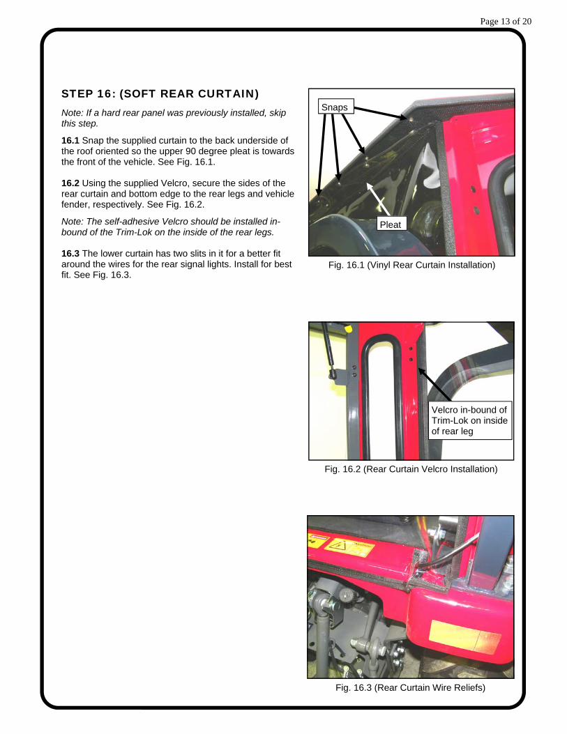
STEP 16: (SOFT REAR CURTAIN)
Note: If a hard rear panel was previously installed, skip this step.
16.1 Snap the supplied curtain to the back underside of the roof oriented so the upper 90 degree pleat is towards the front of the vehicle. See Fig. 16.1. 16.2 Using the supplied Velcro, secure the sides of the rear curtain and bottom edge to the rear legs and vehicle fender, respectively. See Fig. 16.2.
Note: The self-adhesive Velcro should be installed in-bound of the Trim-Lok on the inside of the rear legs. 16.3 The lower curtain has two slits in it for a better fit around the wires for the rear signal lights. Install for best fit. See Fig. 16.3.
Fig. 16.1 (Vinyl Rear Curtain Installation)
Fig. 16.2 (Rear Curtain Velcro Installation)
Fig. 16.3 (Rear Curtain Wire Reliefs)
Velcro in-bound of Trim-Lok on inside of rear leg
Pleat
Snaps
Page 14 of 20
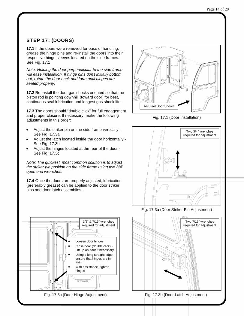
STEP 17: (DOORS)
17.1 If the doors were removed for ease of handling, grease the hinge pins and re-install the doors into their respective hinge sleeves located on the side frames. See Fig. 17.1
Note: Holding the door perpendicular to the side frame will ease installation. If hinge pins don’t initially bottom out, rotate the door back and forth until hinges are seated properly. 17.2 Re-install the door gas shocks oriented so that the piston rod is pointing downhill (toward door) for best, continuous seal lubrication and longest gas shock life. 17.3 The doors should “double click” for full engagement and proper closure. If necessary, make the following adjustments in this order: Adjust the striker pin on the side frame vertically -
See Fig. 17.3a Adjust the latch located inside the door horizontally -
See Fig. 17.3b Adjust the hinges located at the rear of the door -
See Fig. 17.3c Note: The quickest, most common solution is to adjust the striker pin position on the side frame using two 3/4” open end wrenches. 17.4 Once the doors are properly adjusted, lubrication (preferably grease) can be applied to the door striker pins and door latch assemblies.
Fig. 17.1 (Door Installation)
Fig. 17.3a (Door Striker Pin Adjustment)
Two 3/4” wrenches required for adjustment
Fig. 17.3b (Door Latch Adjustment)
Two 7/16” wrenches required for adjustment
Fig. 17.3c (Door Hinge Adjustment)
3/8” & 7/16” wrenches required for adjustment
Loosen door hinges
Close door (double click) - Lift up on door if necessary
Using a long straight edge, ensure that hinges are in-line
With assistance, tighten hinges
All-Steel Door Shown
Page 15 of 20
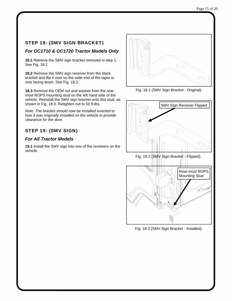
STEP 18: (SMV SIGN BRACKET)
For GC1710 & GC1720 Tractor Models Only 18.1 Retrieve the SMV sign bracket removed in step 1. See Fig. 18.1 18.2 Remove the SMV sign receiver from the black bracket and flip it over so the wide end of the taper is now facing down. See Fig. 18.2. 18.3 Remove the OEM nut and washer from the rear-most ROPS mounting stud on the left hand side of the vehicle. Reinstall the SMV sign bracket onto this stud, as shown in Fig. 18.3. Retighten nut to 50 ft-lbs.
Note: The bracket should now be installed inverted to how it was originally installed on the vehicle to provide clearance for the door. STEP 19: (SMV SIGN)
For All Tractor Models
19.1 Install the SMV sign into one of the receivers on the vehicle.
Fig. 18.1 (SMV Sign Bracket - Original)
Fig. 18.2 (SMV Sign Bracket - Flipped)
SMV Sign Receiver Flipped
Fig. 18.3 (SMV Sign Bracket - Installed)
Rear-most ROPS Mounting Stud

Page 16 of 20
POP-OUT WINDSHIELD
Your GC1700 series cab comes equipped with a pop-out windshield for ventilation. To open the windshield, simply lift up on both of the pop-out latches and rotate until the latches rest in the over-center position. LIFT-OFF DOORS
For added ventilation, the doors on the GC1700 series cab lift off in seconds without tools. To lift off:
1) Disconnect the gas shock from the side frame by depressing the orange activator. 2) Rotate the doors 90 to the side frame and lift. Store the doors in a safe location to prevent damage.
Pop-Up Roof
This cab features a hinged and gas shock supported roof. This feature allows for backhoe operation on GC1710 & GC1720 tractor models, as well as provides additional ventilation on all tractor models. To operate the roof, simply press up on the yellow lever on the quick release latches. It may help to pull down slightly on the grab handles while releasing the latches. To lock the roof in the down position, simply pull down on the plastic grab handles until each latch has double clicked. Note: Pull down on each handle at the same time to ensure accurate positioning of the latches.
REMOVABLE HARD REAR PANEL
For GC1710 & GC1720 Tractor Models Only
In order to use the backhoe on GC1710 & GC1720 model tractors, some conversion of the cab is necessary. First raise the roof per the instructions above. Second, remove the rear panel. To remove the rear panel: 1) Release the two latches towards the bottom of the rear panel. It may be necessary to push out on the lower section of the rear panel to prevent the latches from re-engaging. 2) From outside of the cab, lift up on the rear panel and pull towards the backhoe. Store the rear panel in a safe location to prevent damage. To reinstall the rear panel, simply align the pins at the top with the receivers on the rear legs and drop into place. Push in on the lower corners of the rear panel to ensure double latching of the quick release latches.
CAB FEATURES & OPERATION
Pop-out Windshield
Lift-Off Doors
Removable Hard Rear Panel (GC1710 & GC1720 Tractor Models Only)

Page 17 of 20
Re-apply lubrication (preferably grease) periodically as needed to the door striker pins, door latch
assemblies, and the door hinges. Check and tighten hardware after 40 hours of operation. Periodically inspect and tighten hardware for
the remainder of the unit’s life. Wash the painted surfaces of the cab with commercial automotive cleaning products. Clean glass windows with glass cleaner. Note: Some windows on the cab are acrylic. DO NOT clean
acrylic windows with harsh chemicals. It will damage the plastic. Mild soap and water should be used on all acrylic windows.
Vinyl components should be washed with a mild solution of warm soapy water. Clear vinyl can be easily scratched. Be careful cleaning frost or snow from rear curtain or soft-side
doors. Do not roll curtains in cold weather. The curtain becomes stiff and may crack. Keep curtain clean.
CARE AND MAINTENANCE
CAB FEATURES & OPERATION
TRACTOR HOOD
Due to the unique design of the tractor hood and cowl interface, care should be used when opening and closing the hood in order to prevent damage. Use the following procedures for best results. Opening the Hood: 1. Pop the windshield open and remove the rubber
rain deflector. 2. Close the windshield. 3. Lift up on the hood latch and rotate the hood
outwards towards the loader bucket. Closing the Hood: 1. Make sure the windshield is closed. 2. Lower the hood towards the cowl. 3. Squeeze the lower points of the hood, to allow it
to pass through the cowl. It may help to insert one side into the cowl opening, and then press inward on the other side to squeeze.
Once the corners have passed through, the hood should drop into position and lock in place. Reinstalling the Rubber Rain Deflector: 1. Open the windshield. 2. Snap the rain deflector in place. 3. Smooth the Velcro down into position and smooth the rubber for the best appearance. 4. Close the windshield.
Squeeze Here
Tractor Hood / Cab Interface
Page 18 of 20
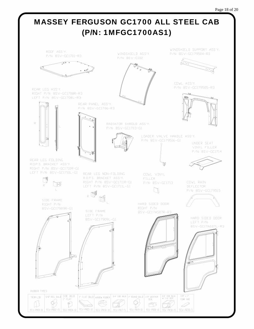
MASSEY FERGUSON GC1700 ALL STEEL CAB (P/N: 1MFGC1700AS1)

Page 19 of 20
MASSEY FERGUSON GC1700 SOFT SIDED CAB (P/N: 1MFGC1700SS1)

Page 20 of 20
ADDITIONAL SERVICE PARTS
QTY. PART NUMBER: DESCRIPTION:
1 8SV‐GC17RF‐R3 ROOF ONLY, WITH TRIM‐LOK AND HEADLINER
1 8SV‐GC17RLM‐CG1 L&R LATCH MOUNT SET WITH LATCHES ASSEMBLED
1 8SV‐PGGC17RLW REAR LEG WINDOW WITH RUBBER
1 8SV‐GL21x32 REAR PANEL GLASS WITH RUBBER
1 8SV‐PGGC17DLW DOOR LOWER WINDOW WITH RUBBER
1 8SV‐SWGC17‐L SLIDER ASSEMBLY, LEFT, WITH RUBBER
1 8SV‐SWGC17‐R SLIDER ASSEMBLY, RIGHT, WITH RUBBER
1 GC1795‐HWK HARDWARE KIT, GC1700
1 9SV‐9GH02 RUBBER KNOB FOR LOADER VALVE HANDLE
1 9SV‐GS02Q GAS SHOCK (12") WITH QUICK RELEASE END (FOR DOOR AND ROOF)
1 9SV‐HWSS WINDSHIELD HINGE KIT WITH SHORT SPACER
1 9SV‐HSLP HINGE SET ‐ LOW PROFILE, BLACK ZINC
1 9SV‐IHRL INSIDE HANDLE ROTARY LATCH KIT
1 9SV‐OHRL OUTSIDE HANDLE ROTARY LATCH KIT
1 9SV‐WL1 WINDSHIELD LATCH KIT 1
1 9PWM110 WINDSHIELD WIPER MOTOR 110°
1 9PWB20‐FB WIPER BLADE, 20" ‐ FLEX
1 9SV‐GS02A BALL STUDS, 10MM (BAG OF 10)
1 9SV‐DP01 DOME PLUG 7/16" (BAG OF 15)
1 9SV‐DP04 DOME PLUG 1‐1/8" (BAG OF 15)
1 9SV‐GH GRAB HANDLE KIT (SET OF 2)
1 9SV‐RFL ROOF LATCH KIT (INCL. L & R)
1 9SV‐DSTRH DOOR STRIKER KIT ‐ INCLUDES CASE HARDENED STRIKER BOLT
1 9PWA14/16 WINDSHIELD WIPER ARM, ADJUSTABLE LENGTH (14" ‐ 16")