master list of energy efficiency actions · pdf file · 2017-10-03master list of...
TRANSCRIPT
Master List of Energy Efficiency Actions Page 1
Data Center
Master List of Energy Efficiency Actions
February 11, 2016
CONTENTS PURPOSE AND HOW TO USE THIS DOCUMENT .............................................................................................. 5 GLOBAL ....................................................................................................................................................................... 6
HIGH LEVEL ACTIONS ................................................................................................................................................ 6 DETAILED ACTIONS .................................................................................................................................................... 6
GL-001: Upgrade All Cooling Supply Fan, Pump, and Cooling Tower Fan Motors to Premium Efficiency ...... 6 ENERGY MONITORING AND CONTROLS .......................................................................................................... 7
HIGH LEVEL ACTIONS ................................................................................................................................................ 7 DETAILED ACTIONS .................................................................................................................................................... 7
EM-001: Perform an Energy Audit ....................................................................................................................... 7 EM-002: Create an Energy Management Plan .................................................................................................... 7 EM-003: Assign an Energy Manager ................................................................................................................... 7 EM-004: Engage Upper Management with a Compelling Life-Cycle Cost Case ................................................ 8 EM-005: Implement an Energy Measurement and Calibration Program ............................................................ 8 EM-006: Conduct Regular Preventive Maintenance ............................................................................................ 8 EM-007: Sub-Meter End-Use Loads and Track Over Time ................................................................................. 8 EM-008: Review Full System Operation and Efficiency on a Regular Basis ....................................................... 8 EM-009: Install Monitoring Equipment to Measure System Efficiency and Performance .................................. 8 EM-010: Raise Awareness and Develop Understanding Among Data Center Staff about the Financial and Environment Impact of Energy Savings ................................................................................................................ 9 EM-011: Train/Raise Awareness of Data Center Designers in the Latest Energy Management Best Practices and Tools ............................................................................................................................................................... 9 EM-012: Use Life Cycle Cost to Make Decisions ................................................................................................. 9 EM-014: Implement a Continuous Commissioning Plan ...................................................................................... 9 EM-015: Create a Project Integration Team ........................................................................................................ 9 EM-016: Use Metrics to Measure Efficiency ..................................................................................................... 10 EM-017: Benchmark Performance ..................................................................................................................... 10 EM-018: Recommission Energy Monitoring Systems ......................................................................................... 10 EM-019: Install an Energy Use Monitoring and Reporting System ................................................................... 10 EM-020: Install a Data Center Infrastructure Management (DCIM) System .................................................... 10 EM-021: Use Visualization Tools ....................................................................................................................... 11 EM-022: Install Dashboards ............................................................................................................................... 11 EM-023: Establish Continual Improvement Goals ............................................................................................. 11
IT EQUIPMENT ........................................................................................................................................................ 12 HIGH LEVEL ACTIONS .............................................................................................................................................. 12 DETAILED ACTIONS .................................................................................................................................................. 12
IT-001: Monitor Utilization of Servers, Storage, and Networks ......................................................................... 12 IT-002: Perform an Audit to Ensure all Operational Servers are Still in Active Use ........................................ 12 IT-003: Evaluate the Potential Savings from Upgrading to Newer IT Equipment ............................................. 13 IT-004: Implement Server Virtualization ............................................................................................................ 13 IT-005: Consolidate to Network-Attached Storage and Diskless Servers .......................................................... 13 IT-006: Assess Data Storage Usage ................................................................................................................... 13
Master List of Energy Efficiency Actions Page 2
IT-007: Reduce the Capacity Requirements of Data Storage Systems ............................................................... 13 IT-008: Evaluate Alternative Financing Methods to Enable Faster Technology Refresh .................................. 13 IT-009: Enable Power Management Features on Servers .................................................................................. 13 IT-010: Consolidate User Data .......................................................................................................................... 14 IT-011: Automate Data Retention and Deletion Policies ................................................................................... 14 IT-012: Obtain Realistic Estimates of IT Equipment Actual Power Use ............................................................ 14 IT-013: Use Vendor Programs to Dispose of Old Servers ................................................................................. 14 IT-014: Specify More Efficient Power Supplies in IT Equipment ....................................................................... 14 IT-015: Specify Computing Performance Metrics for New IT Equipment ......................................................... 14 IT-016: Turn Off Unused Equipment .................................................................................................................. 15 IT-019: Virtualize ................................................................................................................................................ 15 IT-020: Install IT Management Systems and Applications ................................................................................. 15 IT-021: Implement Liquid Cooling ..................................................................................................................... 15
ENVIRONMENTAL CONDITIONS ....................................................................................................................... 16 HIGH LEVEL ACTIONS .............................................................................................................................................. 16 DETAILED ACTIONS .................................................................................................................................................. 16
EC-001: Measure the Return Temperature Index (RTI) and Rack Cooling Index (RCI) ................................... 16 EC-002: Increase the Supply Air Temperature ................................................................................................... 16 EC-003: Provide Warmer Temperatures at the IT Equipment Intakes ............................................................... 16 EC-004: Place Temperature and Humidity Sensors to Mimic the IT Equipment Intake Conditions ................. 17 EC-005: Recalibrate the Temperature and Humidity Sensors ........................................................................... 17 EC-006: Network the CRAC/CRAH/AHU Controls ........................................................................................... 17 EC-007: Add Personnel and Cable Grounding to Allow Lower IT Equipment Intake Humidity ....................... 17 EC-008: Disable or Eliminate Humidification Controls or Decrease the Humidification Setpoint .................. 18 EC-009: Disable or Eliminate Dehumidification Controls or Increase the Dehumidification Setpoint ............ 18 EC-010: Change the Type of Humidifier ............................................................................................................ 18 EC-011: Change Cooling Unit Air Temperature Setpoints Based on IT Equipment Thermal Demand ............ 18 EC-012: Use an Enthalpy Sensor to Control the Airside Economizer ............................................................... 18 EC-013: Follow ASHRAE Guidelines ................................................................................................................. 18 EC-014: Operate at the Maximum ASHRAE Recommended Temperature Range (80.6°F) .............................. 19 EC-015: Anticipate that Servers will Occasionally Operate in a Higher, but Allowable, Range (89.6°F) ....... 19 This is true even when operating in an ASHRAE-recommended range. ............................................................. 19
COOLING AIR AND AIR MANAGEMENT ......................................................................................................... 20 HIGH LEVEL ACTIONS .............................................................................................................................................. 20 DETAILED ACTIONS .................................................................................................................................................. 21
AM-001: Ensure Adequate Match between Heat Load and Effective Raised-Floor Plenum Height ................. 21 AM-002: Provide Adequate Ceiling Supply/Return Plenum Height ................................................................... 21 AM-003: Provide Adequate Clear Ceiling .......................................................................................................... 21 AM-004: Use Existing Dropped Ceiling as Return Plenum ............................................................................... 21 AM-005: Remove Abandoned Cable and Other Obstructions ............................................................................ 21 AM-006: Implement a Cable Mining Program ................................................................................................... 21 AM-007: Implement Alternating Hot and Cold Aisles ........................................................................................ 22 AM-008: Provide Physical Separation of Hot and Cold Air .............................................................................. 22 AM-009: Convert Constant Speed Fans to Variable Speed Fans (VFDs) .......................................................... 22 AM-010: Configure Equipment in Straight Rows ............................................................................................... 22 AM-011: Place Supply Air Devices in Cold Aisles Only .................................................................................... 22 AM-012: Implement a Tile/Diffuser Location Program ..................................................................................... 22 AM-013: Use Appropriate Overhead Diffusers .................................................................................................. 23 AM-014: Place Air Returns at High Elevation ................................................................................................... 23 AM-015: Take Return Air from Hot Aisles ......................................................................................................... 23 AM-016: Provide Adequate Raised Floor Plenum Pressure .............................................................................. 23 AM-017: Seal Raised Floor Leaks ...................................................................................................................... 23 AM-018: Implement a Floor Tightness Program ................................................................................................ 23 AM-019: Use Supplemental Cooling .................................................................................................................. 23 AM-020: Line up CRAC/CRAH/AHU Units with Hot Aisles .............................................................................. 24

Master List of Energy Efficiency Actions Page 3
AM-021: Ensure an Adequate Ratio of System Flow to Rack Flow ................................................................... 24 AM-022: Balance the Air Distribution System .................................................................................................... 24 AM-023: Use IT Equipment with High Design Temperature Rise ..................................................................... 24 AM-024: Use IT Equipment with Front to Rear Cooling Airflow ...................................................................... 24 AM-025: Remove Cosmetic Doors from IT Equipment Racks ............................................................................ 24 AM-027: Maintain Tight Racks and Rows .......................................................................................................... 24 AM-028: Implement a Rack and Row Tightness Program .................................................................................. 25 AM-029: Maintain Unbroken Rows .................................................................................................................... 25 AM-030: Shut off CRAC/CRAH Units ................................................................................................................. 25 AM-031: Implement an Air Balancing Program ................................................................................................ 25 AM-032: Control All Supply Fans in Parallel .................................................................................................... 25 AM-033: Eliminate Pre-Filters ........................................................................................................................... 25 AM-034: Change Filters to Appropriate MERV Rating ..................................................................................... 25 AM-035: Seal Ducts or Casings to Reduce Leakage .......................................................................................... 26 AM-036: Fix System Effects in Air Distribution System ..................................................................................... 26 AM-037: Change CRAC/CRAH/AHU Fan Motors to Premium Efficiency ........................................................ 26 AM-038: Add an Airside Economizer to the AHU .............................................................................................. 26 AM-039: Retrocommission the Airside Economizers ......................................................................................... 26 AM-040: Replace the Existing CRAC/CRAH/AHU Units with More Efficient Equipment ................................ 26 AM-041: Replace Dirty CRAC/CRAH/AHU Filters ........................................................................................... 26 AM-042: Convert the Data Center CRAC/CRAH/AHU Air Temperature Control to Rack Inlet Air Temperature Control ........................................................................................................................................... 26
COOLING PLANT .................................................................................................................................................... 27 HIGH LEVEL ACTIONS .............................................................................................................................................. 27 DETAILED ACTIONS .................................................................................................................................................. 27
Plant Type: All .................................................................................................................................................... 27 CP-011: Right-Size the Cooling Plant ................................................................................................................ 27 CP-012: Recover Waste Heat for Heating Uses in Other Spaces ...................................................................... 27 CP-041: Install Rear Door Heat Exchanger (RDHx) for High-Density Racks .................................................. 28 CP-043: Provide Liquid-Based Heat Removal (Liquid to Chip) ........................................................................ 28 CP-044: Implement Airside Economizing ........................................................................................................... 28 Plant Type: Chilled Water .................................................................................................................................. 28 CP-003: Evaluate Chillers for Replacement ....................................................................................................... 28 CP-004: Optimize Cooling Plant Controls ......................................................................................................... 29 CP-005: Convert all 3-Way CHW Valves to 2-Way ........................................................................................... 29 CP-007: Select Chiller for Optimum Operating Efficiency ................................................................................ 29 CP-010: Monitor System Efficiency .................................................................................................................... 29 CP-013: Add Integrated Waterside Economizer to CHW Plant ......................................................................... 30 CP-015: Recalibrate Chilled Water Supply Temperature Sensors. .................................................................... 30 CP-016: Recalibrate the Condenser Water Supply Temperature Sensors. ........................................................ 30 CP-018: Retrofit Constant-Speed Chiller with Variable Speed Drive (VSD) ..................................................... 30 CP-019: Trim Pump Impeller and Open Triple Duty Valve ............................................................................... 31 CP-020: Remove Suction Diffusers Where Possible ........................................................................................... 31 CP-021: Convert Primary/Secondary Chilled Water Pumping System to Primary-Only .................................. 31 CP-022: Install High Efficiency Pumps .............................................................................................................. 31 CP-023: Specify an Untrimmed Impeller, Use a VFD to Limit Pump Speed, and Match the Pump Motor Size to the Design Flow Rate .......................................................................................................................................... 31 CP-024: Reduce the Chilled Water Supply Pressure Setpoint ............................................................................ 32 CP-025: Implement a Chilled Water Pumping Pressure Setpoint Reset ............................................................ 32 CP-026: Optimize the Number of Pumps Running in a Bank of Variable-Speed Pumps ................................... 33 CP-027: Use VFD to Adjust Condenser Water Flow Rate ................................................................................. 33 CP-030: Specify a High Efficiency Air-Cooled Chiller ...................................................................................... 33 CP-033: Specify an Evaporative Cooled-Chiller ................................................................................................ 33 CP-035: Implement a Chilled Water Storage System ......................................................................................... 34 CP-036: Decrease the Condenser Water Temperature Setpoint ........................................................................ 34 CP-037: Eliminate Low Chilled Water Delta-T .................................................................................................. 35

Master List of Energy Efficiency Actions Page 4
CP-038: Implement Variable Condenser Water Flow ........................................................................................ 35 CP-039: Raise the Chilled Water Supply Temperature Setpoint ........................................................................ 36 CP-040: Reduce the Condenser Water Flow Rate .............................................................................................. 37 CP-045: Use Dry Coolers to Treat Chilled Water Return .................................................................................. 38 Plant Type: Direct Expansion (DX) .................................................................................................................... 39 CP-017: Convert Air-Cooled DX CRACs to Water-Cooled DX CRACs ............................................................ 39 CP-029: Specify High Efficiency DX Cooling Units ........................................................................................... 39 CP-034: Replace the DX Cooling System with a Chilled Water Cooling System .............................................. 39 CP-042: Use a Centralized Cooling System Instead of Individual DX Systems ................................................. 40 Cooling Towers ................................................................................................................................................... 40 CP-001: Add VSDs to Cooling Tower Fans ....................................................................................................... 40 CP-002: Convert Cooling Towers from Series Staging to Parallel Staging ...................................................... 40 CP-008: Select High Efficiency Cooling Towers ................................................................................................ 40 CP-014: Improve Cooling Tower Water Treatment to Reduce Energy Use ....................................................... 40 CP-028: Increase Cooling Tower Capacity ........................................................................................................ 41 CP-032: Specify a Low Approach Temperature Cooling Tower ........................................................................ 41
IT POWER DISTRIBUTION CHAIN ..................................................................................................................... 42 HIGH LEVEL ACTIONS .............................................................................................................................................. 42 DETAILED ACTIONS .................................................................................................................................................. 42
ED-001: Reconfigure the UPS Topology for More Efficient Operation ............................................................. 42 ED-002: Install a Modular UPS ......................................................................................................................... 42 ED-003: Shut Down UPS Modules and PDUs when Redundancy Level is High Enough ................................. 42 ED-004: Use UPS without Input Filters ............................................................................................................. 43 ED-005: Right-Size the Datacenter Power Equipment ....................................................................................... 43 ED-006: Use High Efficiency MV and LV Transformers ................................................................................... 43 ED-007: Reduce the Number of Transformers Upstream and Downstream of the UPS .................................... 43 ED-008: Locate Transformers Outside the Datacenter ...................................................................................... 43 ED-009: Maintain Total Harmonic Distortion at Main Feeder Panel at Less Than 8% ................................... 43 ED-010: Maintain Power Factor at Main Feeder Panel at 0.90 or Higher ....................................................... 44 ED-011: Retrofit IT Equipment to Maintain High Power Factor and Low Total Harmonic Distortion ............ 44 ED-012: Use 480V Instead of 208V Static Switches ........................................................................................... 44 ED-013: Use Alternate Power Source to Warm Generator Blocks .................................................................... 44 ED-014: Use Chilled Water Return to Warm Generator Blocks ........................................................................ 44 ED-015: Apply Thermostat Control to Generator Block Heaters ...................................................................... 44 ED-016: Install Power Analyzer Meters at Critical Components ...................................................................... 44 ED-017: Specify High Efficiency Power Supplies .............................................................................................. 45 ED-018: Eliminate Redundant Power Supplies .................................................................................................. 45 ED-019: Eliminate UPS Systems ........................................................................................................................ 45 ED-020: Bypass the UPS .................................................................................................................................... 45 ED-021: Supply DC Voltage to IT Rack ............................................................................................................. 45 ED-022: Perform an Infra-Red Test ................................................................................................................... 45 ED-023: Perform Routine Maintenance and Testing of the Electric Distribution System ................................. 46 ED-024: Maintain Balanced PDU Loads ........................................................................................................... 46 ED-025: Change UPS DC Capacitors ................................................................................................................ 46 ED-026: Look for the Simple Energy Saving Actions First ................................................................................ 46 ED-027: Account for Operating Cost As Well As First Cost .............................................................................. 46 ED-028: Implement Renewable Energy Sources ................................................................................................ 46
LIGHTING .................................................................................................................................................................. 47 HIGH LEVEL ACTIONS .............................................................................................................................................. 47 DETAILED ACTIONS .................................................................................................................................................. 47
LT-001: Install Energy-Efficient Lamps and Ballasts ........................................................................................ 47 LT-002: Install Occupancy Sensors to Control Lights ....................................................................................... 47 LT-003: Install Peak Shaving Devices on Lighting Systems ............................................................................... 47
APPENDIX A: NOMENCLATURE ......................................................................................................................... 48

Master List of Energy Efficiency Actions Page 5
Purpose and How to use this Document The Master List is a living document of best practice recommendations (actions) to increase energy efficiency in data centers. Designed for data center owners, operators, and qualified assessors, this document provides actionable guidance to both prioritize and implement energy saving measures in data centers. The Master List can be used as a stand-alone reference document for in-house improvements or to inform an energy assessment report being prepared for an external organization. More specifically, individuals can copy and paste relevant actions into an action plan or into the recommendations section of an energy assessment report. The Master List is divided into eight sections that represent data center subsystems and other areas that deserve attention:
• Global (GL) • Energy Monitoring and Controls (EM) • IT Equipment (IT) • Environmental Conditions (EC) • Cooling Air and Air Management (AM) • Cooling Plant (CP) • IT Power Distribution Chain (ED) • Lighting (LT)
Each section starts with high-level actions, common energy savings measures with the highest potential impact. Underneath the high-level actions are detailed actions that provide technical advice on implementation and illustrate the less-common opportunities to reduce energy use in data centers. A defined nomenclature list is also available in the appendix. The Master List is maintained by the Center of Expertise for Energy Efficiency in Data Centers (CoE), which is hosted by the Lawrence Berkeley National Laboratory and sponsored by the U.S. Department of Energy. CoE offers the following tools that align with the Master List or directly draw upon it to provide tailored recommendations:
• Data Center Profiler (DC Pro), a web-based “early stage” scoping tool that estimates Power Usage Effectiveness (PUE): datacenters.lbl.gov/dcpro
• The Data Center Air Management Tool, an Excel-based tool that estimates energy and cost savings from implementing recommended actions for effective air management: https://datacenters.lbl.gov/tools/5-data-center-air-management-tool-featured
• Energy Assessment Report Template, a Word document that can easily be filled in with site data to report data center energy efficiency assessment findings: https://datacenters.lbl.gov/tools/7-energy-assessment-report-template-featured
Please send suggested improvements to the Data Center Master List of Energy Efficiency Actions to [email protected]

Master List of Energy Efficiency Actions Page 6
Global
High Level Actions Action
No. Action Name Refer to Detailed Actions
1 Use Premium Efficiency Motors GL-001
Detailed Actions
GL-001: Upgrade All Cooling Supply Fan, Pump, and Cooling Tower Fan Motors to Premium Efficiency Premium efficiency motors are generally a few percent more efficient than their baseline counterparts. The efficiency gains are modest, but the incremental first cost tends to be low as well, especially when replacing existing motors that have reached the end of their service life. Specifying a premium efficiency motor is usually cost effective for applications with long or continuous runtimes.

Master List of Energy Efficiency Actions Page 7
Energy Monitoring and Controls
High Level Actions Action
No. Action Name Refer to Detailed Actions
1 Create Project Integration Team EM-015 2 Establish Continual Improvement Goals EM-023 3 Use Metrics to Measure Efficiency EM-016 4 Benchmark Performance EM-001, EM-017 5 Evaluate Monitoring Systems to Enhance Real-Time
Management and Efficiency EM-019
6 Install Power Monitoring EM-007 7 Use Visualization Tools EM-021 8 Dashboards EM-022 9 Install an Enterprise Information System (EIS) to
Manage and Sustain Energy Efficiency EM-009, EM-019, EM-022
10 System Integration Including Building Automation System (BAS)
EM-014
Detailed Actions
EM-001: Perform an Energy Audit The first step towards more energy-efficient operation is to quantify how efficiently your facility is currently operating. An audit will reveal how the total energy use of the facility is distributed among the IT equipment and its support systems -- power distribution, cooling, humidity control, etc. Comparing your results against public benchmark data may indicate the where the best opportunities for cost-effective improvements are.
EM-002: Create an Energy Management Plan Maintaining long-term energy-efficient operation of your facility is best accomplished by creating and executing an Energy Management Plan. This plan will identify who the responsible parties are and what the energy management goals are. It will address how to collect measurements of system performance, how the data is managed and interpreted, and the process of identifying, funding, and implementing energy efficiency actions.
EM-003: Assign an Energy Manager If your facility does not already have an Energy Manager, consider assigning one. Efforts to improve energy efficiency often falter when there is no clearly identified "champion" to lead and coordinate.

Master List of Energy Efficiency Actions Page 8
EM-004: Engage Upper Management with a Compelling Life-Cycle Cost Case Some energy efficiency actions have little or no first cost to implement, but many others do. Even if a proposed action has a very rapid payback, management may choose not to fund it based on the cost of implementation. A clearly presented analysis of the return on investment of the proposed action will help management compare it to alternate investment opportunities.
EM-005: Implement an Energy Measurement and Calibration Program It is often said, "you can't manage what you don't measure". Identify the key parameters of your systems that indicate how well they are performing. Determine which of these parameters are already being monitored and what your recording capabilities are. Add instrumentation to capture the parameters that are currently not monitored. Finally, implement a program to regularly calibrate your sensors to ensure that you always collect accurate readings.
EM-006: Conduct Regular Preventive Maintenance Data center support systems are more likely to operate efficiently when they are kept in tune. It is often the case that a support system is meeting its nominal requirements, there are no alarm conditions, but the system is using more energy that it was designed to. Preventive maintenance will bring these situations to light and correct them before a lot of energy waste occurs.
EM-007: Sub-Meter End-Use Loads and Track Over Time Many data centers have only a few main energy meters (electric, gas, etc.). These typically report the total energy use of the facility accurately, but they cannot indicate how the energy use is distributed among the IT equipment and support systems. Installing sub-meters at key locations provides a powerful tool for measuring the energy performance of individual systems. Providing these sub-meters with recording capability allows you to monitor system performance over time, providing evidence of degradations and improvements.
EM-008: Review Full System Operation and Efficiency on a Regular Basis You may already be monitoring some of your data center support systems and are satisfied that they are operating efficiently, but it is important to monitor the energy efficiency of the data center as a whole. The common "big picture" metric is PUE (Power Usage Effectiveness). This measurement indicates how much energy the support systems use in comparison to the IT equipment itself. The less energy the support systems use for a given IT load, the more efficiently the facility operates. Continuously monitoring this ratio is the best way to keep track of the performance of the whole data center.
EM-009: Install Monitoring Equipment to Measure System Efficiency and Performance If you do not have permanent instruments installed to measure key performance parameters, you can install temporary instruments to obtain the same information for selected periods. Electric power meters, chilled water flow meters, and temperature sensors can be quickly deployed and will quantify system performance.

Master List of Energy Efficiency Actions Page 9
EM-010: Raise Awareness and Develop Understanding Among Data Center Staff about the Financial and Environment Impact of Energy Savings Data center staff typically has a list of priorities. Maintaining continuous up-time is usually first followed by providing capacity for future growth. Energy efficiency is usually third or fourth, at best. Implementing and preserving energy efficient operation is helped by coaching staff on how energy efficiency can increase data center capacity, save money, and support the company's overall environmental goals.
EM-011: Train/Raise Awareness of Data Center Designers in the Latest Energy Management Best Practices and Tools The best data center energy efficiencies are achieved when the efficiency is considered and included in the design of the data center layout and support systems (electric distribution, cooling, lighting) from the beginning.
EM-012: Use Life Cycle Cost to Make Decisions Project decisions are often made on the basis of first cost only (the cost of purchasing and installing components and systems). A more optimal fiscal strategy is to consider the life cycle cost of each component and system. Such strategy considers not only first cost but also operating and maintenance cost over its lifetime including disposal cost. Data centers have high power demand in terms of Watt per square foot, which means the energy cost of operating a data center over time can exceed the first cost. An energy-efficient data center, examined from the standpoint of life cycle cost, can justify the purchase of more efficient (costly) equipment.
EM-014: Implement a Continuous Commissioning Plan Commissioning is performed when bringing a new data center on line with the design intent. It ensures that all the support systems are performing as intended and have adequate capacity. Since data centers have dynamic environments that can change significantly over just a few years, commissioning is also sometimes performed later in the data center life cycle (often called retro-commissioning) maybe in conjunction with an energy assessment. Lastly, continuous commissioning calls for “continuous” checking of system health, capacity, and efficiency. This alerts facility operators of negative trends, giving them time to adapt and maintain high operating efficiency.
EM-015: Create a Project Integration Team A major step towards more energy-efficient operation is to create a team. The team then sets a goal to improve data center energy efficiency and reduce energy use by federal mandate. The team should include both Facilities and IT personnel to resolve potential communication gaps between these two groups. The process can include:
1. Set a goal to improve data center energy efficiency and reduce energy use

Master List of Energy Efficiency Actions Page 10
2. Resolve potential communication gaps between IT and Facilities organizations. Gaps usually exist when there are organizational issues, cultural differences, especially between employees and outsourced management.
3. Make sure the goals of operational activities and services (e.g., the implementation of energy efficiency measures such as installation and commissioning of new systems) are well defined and discussed with all parties.
EM-016: Use Metrics to Measure Efficiency Data center efficiency can’t be effectively managed without measured data. There are many different efficiency metrics that can be applied to data center support systems – Power Usage Effectiveness (PUE), Cooling System Efficiency, Electric Distribution Efficiency, and more. It is important to become familiar with different metrics to determine which ones are most appropriate for a given data center. Then determine what measurement devices are needed to collect the data and calculate the metrics.
EM-017: Benchmark Performance Benchmarking energy performance usually entails the comparison of a data center’s energy use data and energy efficiency metrics to other data centers. However, performance can also be benchmarked against a data center’s own data and metrics over time and against internal improvement goals (e.g., 15% reduction in energy use by the following year).
EM-018: Recommission Energy Monitoring Systems Energy monitoring systems rely on sensors and meters to provide raw data. Inaccurate data can lead to false conclusions and wasted effort. Schedule periodic recommissioning of the monitoring system, including calibration of sensors and meters.
EM-019: Install an Energy Use Monitoring and Reporting System Data centers consume a lot of energy – not only the IT equipment itself but all of the support systems as well. Even small gains in energy efficiency tend to achieve large energy savings. Knowing where energy is being used in the data center, and how efficiently, is key to capturing the savings. If an energy monitoring system is not in place yet, consider installing one.
EM-020: Install a Data Center Infrastructure Management (DCIM) System Install a Data Center Infrastructure Management (DCIM) system to monitor, manage, and control energy efficiency, inventory, design, procurement, and it/infrastructure capacity and redundancy.

Master List of Energy Efficiency Actions Page 11
EM-021: Use Visualization Tools Tables of instrument readings often require a trained eye to interpret. Putting the data in visual form – charts, graphs, maps – are usually the best way to quickly assess how systems are performing and where the trouble spots are.
EM-022: Install Dashboards A data center dashboard is analogous to a car’s dashboard – it provides an overview of real time data of key variables in an easy-to-interpret format. From an energy efficiency perspective, having real time readout of key efficiency metrics is a great way to focus and sustain attention on the issue. See Action EM-016 for suggested metrics.
EM-023: Establish Continual Improvement Goals Establish continual improvement goals (e.g., 15% reduction in energy use by the following year).
Master List of Energy Efficiency Actions Page 12
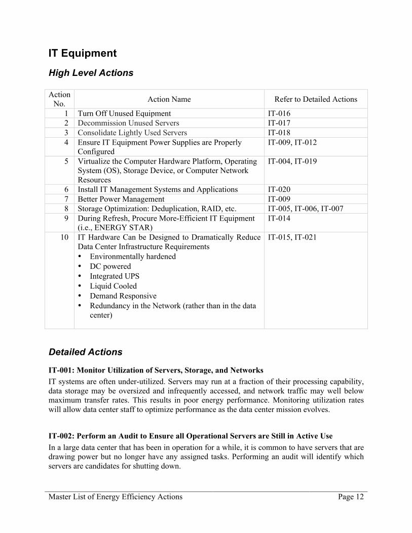
IT Equipment
High Level Actions Action
No. Action Name Refer to Detailed Actions
1 Turn Off Unused Equipment IT-016 2 Decommission Unused Servers IT-017 3 Consolidate Lightly Used Servers IT-018 4 Ensure IT Equipment Power Supplies are Properly
Configured IT-009, IT-012
5 Virtualize the Computer Hardware Platform, Operating System (OS), Storage Device, or Computer Network Resources
IT-004, IT-019
6 Install IT Management Systems and Applications IT-020 7 Better Power Management IT-009 8 Storage Optimization: Deduplication, RAID, etc. IT-005, IT-006, IT-007 9 During Refresh, Procure More-Efficient IT Equipment
(i.e., ENERGY STAR) IT-014
10 IT Hardware Can be Designed to Dramatically Reduce Data Center Infrastructure Requirements • Environmentally hardened • DC powered • Integrated UPS • Liquid Cooled • Demand Responsive • Redundancy in the Network (rather than in the data
center)
IT-015, IT-021
Detailed Actions
IT-001: Monitor Utilization of Servers, Storage, and Networks IT systems are often under-utilized. Servers may run at a fraction of their processing capability, data storage may be oversized and infrequently accessed, and network traffic may well below maximum transfer rates. This results in poor energy performance. Monitoring utilization rates will allow data center staff to optimize performance as the data center mission evolves.
IT-002: Perform an Audit to Ensure all Operational Servers are Still in Active Use In a large data center that has been in operation for a while, it is common to have servers that are drawing power but no longer have any assigned tasks. Performing an audit will identify which servers are candidates for shutting down.

Master List of Energy Efficiency Actions Page 13
IT-003: Evaluate the Potential Savings from Upgrading to Newer IT Equipment IT technology evolves rapidly, and improvements in energy performance are often provided in newer equipment. A cost-benefit analysis will reveal when it makes economic sense to replace existing equipment. During refresh, procure more-efficient IT equipment (e.g., ENERGY STAR-qualified). In the financial analysis, do not neglect the energy cost savings that will be realized in the data center support systems (electric distribution, cooling) as well as the IT equipment itself.
IT-004: Implement Server Virtualization Virtualization techniques can consolidate computing operations on fewer servers, permitting shutting down or eliminating some servers and increasing computation-per-Watt efficiency.
IT-005: Consolidate to Network-Attached Storage and Diskless Servers Servers typically have on-board mechanical disk drives. These drives are responsible for a significant percentage of the server's total energy use, but they often have a low utilization rate. Converting to solid-state memory at the servers, or consolidating to a network-attached (NAS or SAN) data storage device may be a path to an effective energy performance improvement.
IT-006: Assess Data Storage Usage It is not uncommon to have more storage allocated to processing tasks than is needed, and to have the storage accessed infrequently. This can result in poor energy performance, as storage devices draw energy whether they are in active use or not. Investigating data storage utilization patterns can reveal opportunities, such as moving less performance-sensitive data to higher capacity, more efficient media.
IT-007: Reduce the Capacity Requirements of Data Storage Systems Your data storage utilization patterns may allow for storage virtualization. In other words, selected processes can be assigned storage limits that, when summed, exceed the actual total provided storage capacity. If the needs of the individual processes for active storage are non-coincident, the actual storage limit will rarely or never be exceeded.
IT-008: Evaluate Alternative Financing Methods to Enable Faster Technology Refresh The computing efficiency of IT equipment increases from one generation to the next. One energy efficiency strategy is to simply refresh the IT equipment in the data center (see Action IT-003: Evaluate the Potential Savings from Upgrading to Newer IT Equipment). If your standard financing method does not support a timely refresh, consider alternatives. Examine purchase vs. lease, and alternate providers of equipment. For federal agencies, Energy Service Performance Contracts (ESPCs) and Utility Energy Service Contracts (UESCs) may be viable options.
IT-009: Enable Power Management Features on Servers Most servers have power management features that allow them to “throttle back” on energy use when the computing load is light. IT managers often disable these features when the servers are

Master List of Energy Efficiency Actions Page 14
installed (for a variety of reasons). Confirm that the power management schemes are truly impairing compute operations before disabling them.
IT-010: Consolidate User Data Data storage devices use energy. If user data is spread across multiple devices but can be consolidated on fewer, the emptied device can be turned off or repurposed.
IT-011: Automate Data Retention and Deletion Policies As data accumulates and grows, a standard response is to add more data storage devices. Compared to the labor cost of manual cleanup, storage is inexpensive. But more storage devices equates to more energy use. Consider an automated solution for implementing data archiving and deletion policies.
IT-012: Obtain Realistic Estimates of IT Equipment Actual Power Use Inexperienced data center designers sometimes use the IT equipment nameplate power supply rating to (over)size data center support systems. The nameplate rating contains electrical safety information. IT equipment essentially never draws its nameplate power; it is often far less. Oversized support systems tend to run inefficiently. Knowing the true power draw (and subsequent heat release) characteristics of the IT equipment allows the designer to specify right-sized support systems.
IT-013: Use Vendor Programs to Dispose of Old Servers Older servers tend to be less energy efficient than new ones. The intent of this action is to physically remove old servers from the facility, reducing the temptation to continue using them. Vendor “take-back” offers the additional advantage of having the equipment recycled in an environmentally responsible manner.
IT-014: Specify More Efficient Power Supplies in IT Equipment This action addresses the final step in the chain of power conversions that occurs between the main power feed to the data center and the end-point of the IT equipment. It can be an effective strategy for reducing load in existing servers that have hot-swappable power supply capability, but most servers are not so equipped. This action is usually most effective for new equipment. A customer has more clout to specify efficient power supplies when placing a large order with a supplier.
IT-015: Specify Computing Performance Metrics for New IT Equipment Future procurements of IT equipment can benefit from use of appropriate performance metrics coupling computational performance with energy performance. Such metrics will allow comparison of overall computing efficiency and will take into account such issues as processor efficiency, hardware/software compatibility, memory efficiency, etc.

Master List of Energy Efficiency Actions Page 15
IT-016: Turn Off Unused Equipment This action expands Action IT-002: Perform an Audit to Ensure All Operational Servers are Still Active to all equipment. UPS units, PDUs, switches, storage arrays, etc. should be turned off if not in use.
IT-019: Virtualize This action expands Action IT-004 Implement Server Virtualization to other IT equipment. As with server virtualization, virtualization of IT equipment (e.g., storage devices and computing platforms) enables equipment that is better utilized and more energy efficient.
IT-020: Install IT Management Systems and Applications IT management systems show the status and computational load of IT equipment, but they can also provide evidence of support system performance via server temperatures, power draw, and fan speed. These indicators can help the data center operator tune the support systems for improved performance.
IT-021: Implement Liquid Cooling All data center cooling systems use a fluid of some type – refrigerant, chilled water – to provide cooling. At some point in the system, cold air is produced and it is this cold air that ultimately enters and cools the IT equipment. In general, the closer the transition from fluid to air is to the IT equipment, the more thermally effective and efficient the cooling system can be. The term “liquid cooling”, as used here, refers to bringing the cooling fluid all the way to the hot surfaces inside the IT equipment, eliminating the transition to cold air altogether. This can provide the most thermally effective and efficient cooling possible. There are several different liquid cooling solutions in the marketplace. They are typically most cost effective when applied to the highest heat density equipment – equipment that is difficult to adequately cool with air-based systems. See also Action CP-043: Provide Liquid-Based Heat Removal (Liquid to Chip)

Master List of Energy Efficiency Actions Page 16
Environmental Conditions
High Level Actions Action
No. Action Name Refer to Detailed Actions
1 At Minimum, Follow ASHRAE Guidelines for Data Center Temperature Ranges
EC-002, EC-013
2 Even Better, Operate at the Maximum ASHRAE Recommended Temperature Range (80.6°F)
EC-002, EC-003, EC-014
3 Anticipate that Servers will Occasionally Operate in a Higher, but Allowable, Range (89.6°F)
EC-002, EC-003, EC-015
4 Minimize or Eliminate Humidity Control Altogether EC-006, EC-008, EC-009
Detailed Actions
EC-001: Measure the Return Temperature Index (RTI) and Rack Cooling Index (RCI) A low air temperature rise across the data center and/or IT equipment intake temperatures outside the recommended range suggest air management problems. A low return temperature is due to by-pass air and an elevated return temperature is due to recirculation air. Estimating the Return Temperature Index (RTI) and the Rack Cooling Index (RCI) will indicate if corrective, energy-saving actions are called for.
EC-002: Increase the Supply Air Temperature A low supply temperature makes the chiller system less efficient and limits the utilization of economizers. Enclosed architectures allow the highest supply temperatures (near the upper end of the recommended intake temperature range) since mixing of hot and cold air is minimized. In contrast, the hottest intake temperature often dictates the supply temperature in open architectures.
EC-003: Provide Warmer Temperatures at the IT Equipment Intakes Specifying a low IT equipment intake temperature causes the cooling system to run less efficiently and limits the utilization of economizers. Target the maximum recommended intake temperature from guidelines issued by ASHRAE (80.6F) and NEBS (80F) depending on the type of electronic equipment in the data or telecom center. If the air distribution system can be modified to deliver air more effectively to the equipment, it may be possible to raise the average intake temperature. This in turn will allow the cooling supply air temperature to be raised, which typically results in more efficient cooling system operation.

Master List of Energy Efficiency Actions Page 17
EC-004: Place Temperature and Humidity Sensors to Mimic the IT Equipment Intake Conditions IT equipment manufacturers design their products to operate reliably within a given range of intake temperature and humidity. The temperature and humidity limits imposed on the cooling system that serves the data center are intended to match or exceed the IT equipment specifications. However, the temperature and humidity sensors are often integral to the cooling equipment and are not located at the IT equipment intakes. The condition of the air supplied by the cooling system is often significantly different by the time it reaches the IT equipment intakes. It is usually not practical to provide sensors at the intake of every piece of IT equipment, but a few representative locations can be selected. Adjusting the cooling system sensor location in order to provide the air condition that is needed at the IT equipment intake often results in more efficient operation.
EC-005: Recalibrate the Temperature and Humidity Sensors Temperature sensors generally have good accuracy when they are properly calibrated (+/- a fraction of a degree), but they tend to drift out of adjustment over time. In contrast, even the best humidity sensors are intrinsically not very precise (+/- 5% Relative Humidity or RH is typically the best accuracy that can be achieved at reasonable cost). Humidity sensors also drift out of calibration. To ensure good cooling system performance, all temperature and humidity sensors used by the control system should be treated as maintenance items and calibrated at least once a year. Twice a year is better to begin with. After a regular calibration program has been in effect for a while, you can gauge how rapidly your sensors drift and how frequent the calibrations should be. Calibrations can be performed in-house with the proper equipment, or by a third-party service.
EC-006: Network the CRAC/CRAH/AHU Controls CRAC/CRAH/AHU units are typically self-contained, complete with an on-board control system and air temperature and humidity sensors. The sensors may not be calibrated to begin with, or they may drift out of adjustment over time. In a data center with many CRAC/CRAH/AHU units it is not unusual to find some units humidifying while others are simultaneously dehumidifying. There may also be significant differences in supply air temperatures. Both of these situations waste energy. Controlling all the CRAC/CRAH/AHU units from a common set of sensors avoids this.
EC-007: Add Personnel and Cable Grounding to Allow Lower IT Equipment Intake Humidity The lower humidity limit in data centers is often set relatively high (40% RH at the IT equipment intake is common) to guard against damage to the equipment due to electrostatic discharge (ESD). Maintaining this level of humidity is energy intensive if the humidifiers use electricity to make steam, which is most common. Energy can be saved if the allowed lower humidity limit can be lowered, particularly if the cooling system has an airside economizer. ESD can be kept in check by conductive flooring materials, good cable grounding methods, and providing grounded wrist straps for technicians to use while working on equipment.

Master List of Energy Efficiency Actions Page 18
EC-008: Disable or Eliminate Humidification Controls or Decrease the Humidification Setpoint Tightly controlled humidity can be very costly in data centers since humidification and dehumidification are involved. A wider humidity range allows significant utilization of free cooling in most climate zones by utilizing effective airside economizers. In addition, open-water systems are high-maintenance items.
EC-009: Disable or Eliminate Dehumidification Controls or Increase the Dehumidification Setpoint Most modern IT equipment is designed to operate reliably when the intake air humidity is between 20% and 80% RH. However, 55% RH is a typical upper humidity level in many existing data centers. Maintaining this relatively low upper limit comes at an energy cost. Raising the limit can save energy, particularly if the cooling system has an airside economizer. In some climates it is possible to maintain an acceptable upper limit without ever needed to actively dehumidify. In this case, consider disabling or removing the dehumidification controls entirely.
EC-010: Change the Type of Humidifier Most humidifiers are heat based, ie., they supply steam to the air stream by boiling water. Electricity or natural gas are common fuel sources. The heat of the steam becomes an added load on the cooling system. An evaporative humidifier uses much less energy. Instead of boiling water, it introduces a very fine mist of water droplets to the air stream. When set up properly the droplets quickly evaporate, leaving no moisture on nearby surfaces. This has an added cooling benefit, as the droplets absorb heat from the air as they evaporate. A wetted media can also be used.
EC-011: Change Cooling Unit Air Temperature Setpoints Based on IT Equipment Thermal Demand IT equipment is designed to operate most reliably within a certain range of intake air temperatures, and a certain temperature rise of the air is expected before it is exhausted. Programming the cooling system to match these temperatures avoids cooling system energy waste due to overcooling the supply air, and ensures reliable IT equipment operation.
EC-012: Use an Enthalpy Sensor to Control the Airside Economizer An economizer can be either a temperature or enthalpy economizer. A temperature economizer is controlled by temperature only. An enthalpy economizer on the other hand is controlled by temperature and humidity (that is, energy content). Using an enthalpy economizer generally saves more energy than using a temperature economizer. However, it is also more complex.
EC-013: Follow ASHRAE Guidelines At minimum, follow ASHRAE guidelines for data center temperature ranges.

Master List of Energy Efficiency Actions Page 19
EC-014: Operate at the Maximum ASHRAE Recommended Temperature Range (80.6°F) EC-015: Anticipate that Servers will Occasionally Operate in a Higher, but Allowable, Range (89.6°F) This is true even when operating in an ASHRAE-recommended range.

Master List of Energy Efficiency Actions Page 20
Cooling Air and Air Management
High Level Actions Action
No. Action Name Refer to Detailed Actions
1 Install the Racks in Rows AM-007, AM-008, AM-010 2 Implement Hot and Cold Aisles AM-007 3 Preserve Any Hot-Aisle/Cold-Aisle Arrangements AM-008, AM-010, AM-011 4 Rearrange Perforated Floor Tiles, Locating Them Only
in Cold Aisles and Matching the Tile Flow Rate with the IT Equipment Airflow Rate
AM-007, AM-008, AM-012
5 Cover Openings Within and Between Racks Note: Investigate openings on top of the racks and devise ways to contain them. Hot aisle containment should address those openings.
AM-007, AM-008, AM-012, AM-017, AM-018
6 Evaluate the Air Path (Under the raised floor or in the ceiling space) and Rearrange the Cables, Wires, and Pipes to Address Possible Congestion in the Cooling Air Path
AM-004, AM-015
7 Seal the Remainder of the Cable Penetrations AM-017, AM-018 8 Separate Cold Air and Hot Air
Note: One of the most effective ways to accomplish this is to contain the hot aisle and create a hot air return path, which can be a ceiling space and chimney above the CRAC, CRAH, or AHU. This strategy will work even if the cold air is distributed from above.
AM-004, AM-015
9 Shut Off Extra CRAC/CRAH/AHU Note: To reduce the cooling redundancy levels while reducing bypass air that lowers the return air temperature on the CRAC/CRAH/AHU
AM-030
10 Reset Each CRAC/CRAH/AHU Chilled Water Valve Setpoint with the Highest Air Intake Temperature at the Racks in that Zone
AM-042
11 Convert the Data Center CRAC/CRAH/AHU Air Temperature Control to the Rack Inlet Air Temperature Control
AM-042
12 Use Modeling Tools such as CFD or Thermal Imaging AM-005 13 Install Variable Frequency Drives (VFDs) on
CRAC/CRAH/AHU Fans with Advanced Control AM-009

Master List of Energy Efficiency Actions Page 21
Detailed Actions
AM-001: Ensure Adequate Match between Heat Load and Effective Raised-Floor Plenum Height The cooling capacity of a raised floor depends on its effective flow area, which can be increased by removing cables and other obstructions that are not in use. Still, the heat density may need to be reduced. Undersized and/or congested plenums often require an overall elevated static pressure to deliver the required airflow. Providing the increased static pressure requires additional fan energy.
AM-002: Provide Adequate Ceiling Supply/Return Plenum Height The plenum height can be increased if the clear ceiling allows. A return plenum often means a lower clear ceiling but allows placing the return grilles directly above the hot aisles. Such a plenum needs to be maintained similar to a raised floor. A shallow plenum may result in high-pressure losses, poor pressure distributions, and high fan-energy costs.
AM-003: Provide Adequate Clear Ceiling Remove the dropped ceiling if not used for air distribution and the clear ceiling is less than 12 feet. Tall open ceilings promote thermal stratification, and the placement of the return grilles is not critical. The stratification ensures that the hot exhaust air is not mixed with the cooler ambient air but is rather returned directly to the air handler. Such ceilings have an unmatched simplicity compared to return plenums.
AM-004: Use Existing Dropped Ceiling as Return Plenum The thermal effectiveness of the data center increases when the return air temperature is maximized, and a return plenum allows the return grilles to be placed directly above the hot aisles. If no dropped ceiling exists, however, installing one is generally not warranted.
AM-005: Remove Abandoned Cable and Other Obstructions Under-floor and over-head obstructions often interfere with the distribution of cooling air. Such interferences can significantly reduce the air handlers’ airflow as well as negatively affect the air distribution. The cooling capacity of a raised floor depends on its effective height, which can be increased by removing obstructions that are not in use.
AM-006: Implement a Cable Mining Program Cable congestion in raised-floor plenums can sharply reduce the total airflow as well as degrade the airflow distribution through the perforated floor tiles. Both effects promote the development of thermal hot spots.

Master List of Energy Efficiency Actions Page 22
AM-007: Implement Alternating Hot and Cold Aisles This is generally the first step towards separating hot and cold air, which is key to air management. Cold air is supplied into the cold front aisles, the IT equipment moves the air from the front to the rear and/or front to the top, and the hot exhaust air is returned to the air handler from the hot rear aisles. Some data centers are not suitable for hot/cold aisles, including those with non-optimal gear (not moving air from front to rear/top).
AM-008: Provide Physical Separation of Hot and Cold Air Physical barriers can successfully be used to avoid mixing the hot and cold air, allowing reduction in airflow and fan energy as well as increase in supply/return temperatures and chiller efficiency. There are four principal ways of providing physical separation:
1. Semi-enclosed aisles such as aisle doors; allows some containment of the cold air. 2. Flexible strip curtains to enclose aisles; allows good separation of hot and cold air. 3. Rigid enclosures to enclose aisles; allows excellent separation of hot and cold air. 4. In-rack ducted exhaust; allows effective containment of the hot exhaust air.
AM-009: Convert Constant Speed Fans to Variable Speed Fans (VFDs) This action allows variation of airflow to meet cooling demand. Traditionally, few CRAC/CRAH/AHU units have the capability to vary the airflow in real time; adjusting the supply temperature is the only option. With variable speed drives, the capacity control can be modified to improve the cooling effectiveness of the electronic equipment as well as save fan and cooling energy. Fan power consumption can be reduced drastically (potential saving up to 60-80% of fan power consumption) with the use of VFDs. This also helps preserve adequate pressurization of the supply plenum (if any) because all fans continue to run, in contrast to action AM-030: Shut off CRAC/CRAH Units.
AM-010: Configure Equipment in Straight Rows Since straight equipment lineups are generally a prerequisite to alternating hot and cold aisles, it should have a very high priority. Straight lineups also allow structured cable management.
AM-011: Place Supply Air Devices in Cold Aisles Only Perforated floor tiles or over-head supply diffusers should only be placed in the cold aisles to match the “consumption” of air by the electronic equipment. Too little or too much supply air results in poor overall thermal and/or energy conditions. Note: the hot aisles are supposed to be hot and supplies should not be placed in those areas.
AM-012: Implement a Tile/Diffuser Location Program A program should be in place to maintain the alternating hot and cold aisle configuration of perforated tiles or over-head diffusers. There is no reason to place tiles or diffusers in the hot equipment aisles.
Master List of Energy Efficiency Actions Page 23
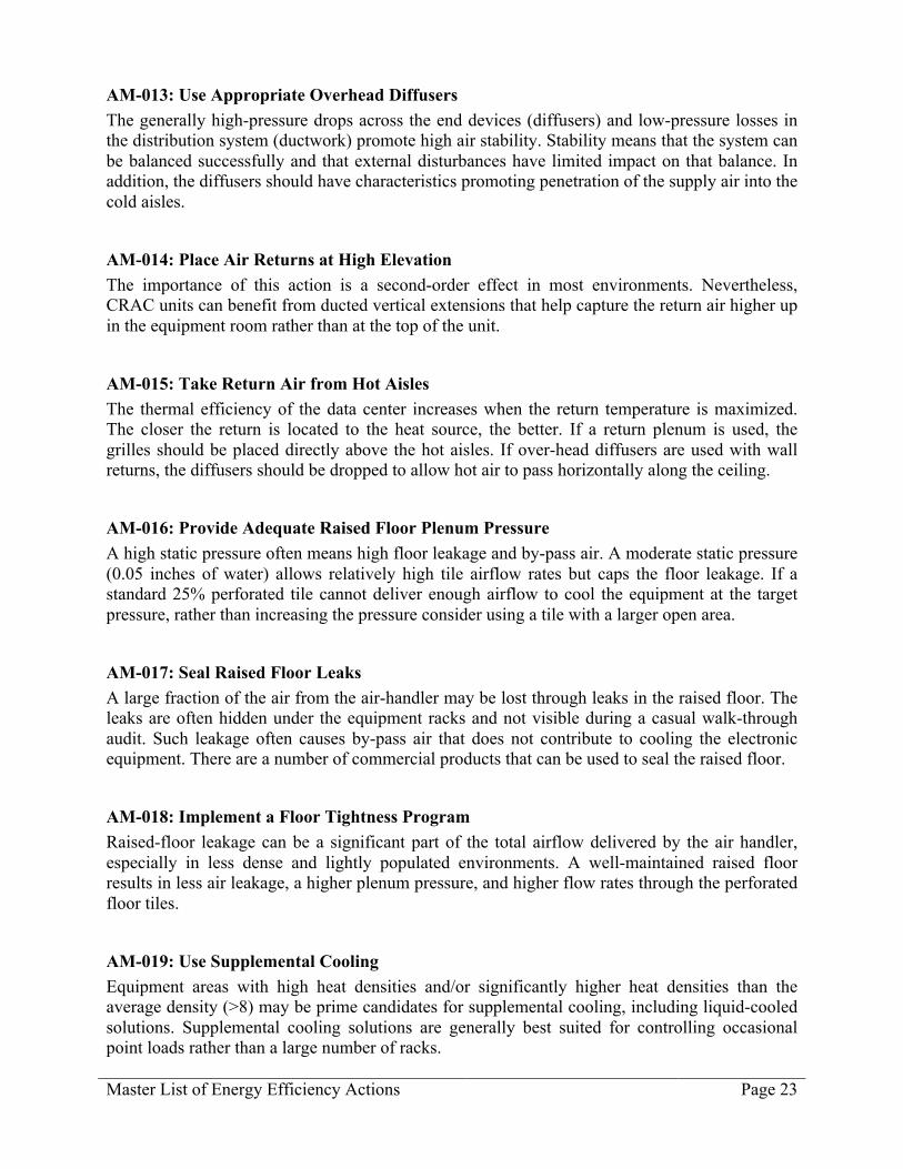
AM-013: Use Appropriate Overhead Diffusers The generally high-pressure drops across the end devices (diffusers) and low-pressure losses in the distribution system (ductwork) promote high air stability. Stability means that the system can be balanced successfully and that external disturbances have limited impact on that balance. In addition, the diffusers should have characteristics promoting penetration of the supply air into the cold aisles.
AM-014: Place Air Returns at High Elevation The importance of this action is a second-order effect in most environments. Nevertheless, CRAC units can benefit from ducted vertical extensions that help capture the return air higher up in the equipment room rather than at the top of the unit.
AM-015: Take Return Air from Hot Aisles The thermal efficiency of the data center increases when the return temperature is maximized. The closer the return is located to the heat source, the better. If a return plenum is used, the grilles should be placed directly above the hot aisles. If over-head diffusers are used with wall returns, the diffusers should be dropped to allow hot air to pass horizontally along the ceiling.
AM-016: Provide Adequate Raised Floor Plenum Pressure A high static pressure often means high floor leakage and by-pass air. A moderate static pressure (0.05 inches of water) allows relatively high tile airflow rates but caps the floor leakage. If a standard 25% perforated tile cannot deliver enough airflow to cool the equipment at the target pressure, rather than increasing the pressure consider using a tile with a larger open area.
AM-017: Seal Raised Floor Leaks A large fraction of the air from the air-handler may be lost through leaks in the raised floor. The leaks are often hidden under the equipment racks and not visible during a casual walk-through audit. Such leakage often causes by-pass air that does not contribute to cooling the electronic equipment. There are a number of commercial products that can be used to seal the raised floor.
AM-018: Implement a Floor Tightness Program Raised-floor leakage can be a significant part of the total airflow delivered by the air handler, especially in less dense and lightly populated environments. A well-maintained raised floor results in less air leakage, a higher plenum pressure, and higher flow rates through the perforated floor tiles.
AM-019: Use Supplemental Cooling Equipment areas with high heat densities and/or significantly higher heat densities than the average density (>8) may be prime candidates for supplemental cooling, including liquid-cooled solutions. Supplemental cooling solutions are generally best suited for controlling occasional point loads rather than a large number of racks.

Master List of Energy Efficiency Actions Page 24
AM-020: Line up CRAC/CRAH/AHU Units with Hot Aisles The CRAC/CRAH/AHU units should be placed to promote an even pressure distribution in the floor plenum. Although it may seem counter-intuitive, center them on the hot aisles rather than on the cold aisles results in better cooling performance. Turning vanes under the units are generally not necessary to redirect the supply air into the floor plenum.
AM-021: Ensure an Adequate Ratio of System Flow to Rack Flow At the data center level, the total supply airflow should closely match the total IT equipment airflow. The Return Temperature Index (RTI) is a measure of the level of net by-pass air or net recirculation air in the equipment room. Both effects are detrimental to the thermal and energy performance of the data center. The target is 100% whereas >100% implies recirculation air and <100% implies by-pass air.
AM-022: Balance the Air Distribution System Over-head ducted systems can be adequately balanced using conventional methods whereas raised-floor systems are balanced by using “enough” perforated tiles. The latter often becomes more an art rather than science, especially since the pressure difference across the floor is small.
AM-023: Use IT Equipment with High Design Temperature Rise A higher temperature rise across the equipment and—in turn—the equipment room allows a lower cooling airflow rate and a higher return temperature. Both effects promote lower energy utilization.
AM-024: Use IT Equipment with Front to Rear Cooling Airflow The Equipment-Cooling (EC) class describes where the entry and exit points for the cooling air are located on the equipment envelope. An optimal class moves air from the cold front aisle to the rear hot aisle, conserving the alternating hot and cold aisles. Non-optimal gear should be isolated rather dictating the cooling requirements for the entire data center.
AM-025: Remove Cosmetic Doors from IT Equipment Racks Such doors often impede the cooling airflow and may promote recirculation within the enclosed cabinet further increasing the equipment intake temperature. Truly cosmetic doors should not be used. If rack doors are necessary for security reasons, provide them with openings to permit adequate cooling airflow. For example, solid doors can be replaced with perforated doors.
AM-027: Maintain Tight Racks and Rows Blanking panels should be used to seal openings under and between equipment racks, between equipment shelves in partially filled racks, or completely empty racks. Managing blanking panels

Master List of Energy Efficiency Actions Page 25
is especially important in hot and cold aisle environments. Blanking panels come in various heights and widths to fit almost any application, and they come in snap-on or screw-in types.
AM-028: Implement a Rack and Row Tightness Program Any opening between the cold aisle and the hot aisle will degrade the separation of hot and cold air. A program should be in place to minimize leakage by maintaining blanking panels and unbroken rows.
AM-029: Maintain Unbroken Rows Broken rows should be filled with empty racks with blanking panels from top to bottom. Managing unbroken equipment rows is especially important in hot and cold aisle environments. Any opening between the aisles will degrade the separation of hot and cold air.
AM-030: Shut off CRAC/CRAH Units If it is determined that a lower airflow volume is desired and the CRAC/CRAH/AHU units do not have variable speed fans, adjustment is limited to shutting off individual units. This is not a precise way of controlling the air volume, but it can still yield acceptable results. Some experimentation may be required to determine which units can be shut off without compromising adequate cooling of the IT equipment.
AM-031: Implement an Air Balancing Program At the data center level, the total supply airflow should closely match the total IT equipment airflow. The Return Temperature Index (RTI) is a measure of net by-pass air or net recirculation air. Both are detrimental to the performance of the data center. The target is 100% whereas >100% implies recirculation air and <100% implies by-pass air. On a row or rack level, air balancing is also important to avoid local by-pass air or recirculation air.
AM-032: Control All Supply Fans in Parallel If all the supply fans serving a given space are identical and equipped with variable speed drives, fan energy is minimized by running all the fans (including redundant units) at the same reduced speed.
AM-033: Eliminate Pre-Filters
AM-034: Change Filters to Appropriate MERV Rating
Master List of Energy Efficiency Actions Page 26
AM-035: Seal Ducts or Casings to Reduce Leakage Although raised-floor systems generally leak significantly more than ducted systems, duct systems should be sealed and maintained to avoid unnecessary large airflow rates and energy costs.
AM-036: Fix System Effects in Air Distribution System
AM-037: Change CRAC/CRAH/AHU Fan Motors to Premium Efficiency
AM-038: Add an Airside Economizer to the AHU If the data center is served by cooling units that can be practically served with outside air, and there is a feasible exhaust air path, consider implementing airside economizing. In economizing mode, 100% outside air is drawn in to the data center and returned to the outdoors after one pass. This scheme will offset or even eliminate cooling compressor energy whenever the energy content of the outside air is less than the energy content of the return air. The higher the nominal return air temperature, the more viable economizing hours there will be. To ensure that summer peak electric demand is not increased due to fan energy, design for low-pressure drop intake and exhaust paths. Off-the-shelf air handlers and AC units can often be ordered with an economizer option direct from the manufacturer.
AM-039: Retrocommission the Airside Economizers While airside economizers can offer large energy savings (particularly in milder climates), they need regular service to operate properly. Outside air temperature sensors that control when the economizer opens and closes must be kept calibrated. The actuators and linkages that control the economizer louvers must be kept lubricated and in adjustment. The entire economizer system should be tested at least once a year to ensure it operates as intended.
AM-040: Replace the Existing CRAC/CRAH/AHU Units with More Efficient Equipment When replacing older units, in addition to specifying units with more efficient fans and fan motors, specify variable speed drives (VFDs or EC Motors) on the fans. See action AM-009: Convert to Variable Speed Fans.
AM-041: Replace Dirty CRAC/CRAH/AHU Filters
AM-042: Convert the Data Center CRAC/CRAH/AHU Air Temperature Control to Rack Inlet Air Temperature Control

Master List of Energy Efficiency Actions Page 27
Cooling Plant
High Level Actions Action
No. Action Name Refer to Detailed Actions
1 Raise the Chilled Water Temperature Note: An increase in chilled water supply temperature setpoint increases chiller efficiency but should only be performed after implementing air management
CP-039
2 Maximize Central Cooling Plant Efficiency CP-007, CP-008, CP-011, CP-012, CP-018, CP-022, CP-023, CP-026, CP-027, CP-028, CP-036, CP-037
3 Install Integrated Water-Side Economizers CP-013 4 Install Dry Coolers
Note: In lieu of or in addition to chillers CP-045
5 Install a Rack Door Heat Exchanger (RDHx) for High-Density Racks Note: This change allows higher cooling water temperatures to be used, which reduces cooling energy use
CP-041
6 Install Direct and Indirect Airside Economizer Note: Use outside air, directly without treatment, for cooling
CP-044
7 Use a Centralized Cooling System Instead of an Individual Direct Expansion (DX) system
CP-042
Detailed Actions
Plant Type: All
CP-011: Right-Size the Cooling Plant Provisioning a data center with oversized cooling units results in the units running at low load factors, where they tend to be least efficient. The cooling plant should be sized to handle the peak expected load, plus a reasonable safety margin. A modular plant is a good choice from an efficiency perspective; it allows cooling units to be brought on line as the data center load grows.
CP-012: Recover Waste Heat for Heating Uses in Other Spaces In buildings that contain data center and office space, the air distribution system can be arranged to take warm return air from the data center and supply it to the office space for heating purposes.

Master List of Energy Efficiency Actions Page 28
CP-041: Install Rear Door Heat Exchanger (RDHx) for High-Density Racks Install Rear Door Heat Exchanger (RDHx) on high-density racks. This modification allows higher cooling water temperatures to be used. If a separate cooling system is provided for these racks, or if the entire data center uses these racks, then cooling can be provided more efficiently. In general, the higher the required supply temperature of the cooling water is, the more efficient the cooling system can be. Some data centers have successfully omitted chillers altogether and use only cooling towers year round to supply water directly to the rack door heat exchangers. This provides large first-cost and operational savings.
CP-043: Provide Liquid-Based Heat Removal (Liquid to Chip) All data center cooling systems use a fluid of some type – refrigerant, chilled water – to provide cooling. At some point in the system, cold air is produced and it this cold air that ultimately enters and cools the IT equipment. In general, the closer the transition from fluid to air is to the IT equipment, the more thermally effective and efficient the cooling system can be. The term “liquid cooling”, as used here, refers to bringing the cooling fluid all the way to the hot surfaces inside the IT equipment, eliminating the transition to cold air altogether. This can provide the most thermally effective and efficient cooling possible. There are several different liquid cooling solutions in the marketplace. The type of cooling system required to support these solutions varies. See also Action IT-021: Implement Liquid Cooling
CP-044: Implement Airside Economizing Airside economizing refers to the scheme of drawing outside air directly into the data center for cooling purposes and exhausting it after one pass. Provided the outside air is cool enough, the mechanical cooling equipment can be shut down; only the fans need to run. If the outside air temperature is higher than the required supply air temperature, but lower than the temperature of the air returning to the cooling equipment, it can still provide partial cooling and reduce the load on the cooling equipment. The effectiveness of this scheme depends on the local climate and the ability to move a relatively large volume of air simultaneously into and out of the building.
Plant Type: Chilled Water
CP-003: Evaluate Chillers for Replacement Chillers are typically the greatest energy-using components in the cooling system. Recent advances in chiller technology, especially variable-speed compressors, offer more efficient operation. For these reasons, it is often worthwhile to examine the cost-effectiveness of replacing existing chillers if they are more than 5 years old or are in poor condition.

Master List of Energy Efficiency Actions Page 29
CP-004: Optimize Cooling Plant Controls There are many ways to optimize the control of chilled water plants. There is much literature available on the subject. Many of the strategies involve automatic resets – of condenser water temperature, condenser water flow rate, cooling tower fan speed, chilled water supply temperature, chilled water pumping pressure, fan speed, etc.
CP-005: Convert all 3-Way CHW Valves to 2-Way Older chilled water distribution systems were typically designed with 3-way valves at the cooling coils. A constant flow of chilled water is delivered to each coil location. Each coil is equipped with a bypass leg, and each 3-way valve modulates to divert as much water through the coil as is currently needed for cooling purposes. The remaining water bypasses the coil. This method is energy intensive. With the advent of inexpensive, reliable variable speed drives for pump motors, the preferred design eliminates the bypasses and replaces the 3-way valves with 2-way valves. The 2-way valves modulate as needed to serve the cooling load, and the pump motor speed varies in response to the demand by maintaining a constant pressure at the far end of the distribution loop. In facilities that experience varying load, it may be cost effective to go one step further and program the control system to vary the pressure setpoint in response to the position of the most-open 2-way valve.
CP-007: Select Chiller for Optimum Operating Efficiency Chillers are selected with a peak load and a safety factor in mind. The chiller plant has to be able to handle the highest expected load with an adequate safety margin. The annual average cooling load, however, is typically considerably less than the peak load. A chiller’s efficiency varies with the load. The shape of the efficiency curve will vary depending on chiller technology type and, to some degree, on what the buyer requests from the manufacturer. Electric chillers tend to be highest single electric power demand in the entire suite of data center support systems. Taking these factors into account, an efficiency-oriented designer will match the expected cooling load profile with the chiller efficiency curve to obtain the most efficient annual average operation.
CP-010: Monitor System Efficiency The actual operating efficiency of a cooling plant cannot be determined without measuring the cooling load it is serving and the power draw of the cooling plant components. Setting up temporary measuring devices will provide a snapshot of the efficiency at one point in time. For more robust plant efficiency management, permanent devices should be installed. The simplest approach is to treat the plant as a “black box”. Assuming an all-electric chilled water plant, install the minimum number of electric meters needed to isolate the total power draw of the plant (chillers, pumps, cooling towers and any other peripherals). On the cooling side, install the minimum number of chilled water temperature sensors and flow meters to capture the
Master List of Energy Efficiency Actions Page 30
total cooling load. The whole-plant efficiency (in kW/ton) is simply the ratio of the power draw (kW) to the cooling load (tons). Extending the distribution of measurement devices to the level of individual chillers provides additional resolution on efficiency. Many chillers have this capability built into their on-board controls.
CP-013: Add Integrated Waterside Economizer to CHW Plant This action is applicable to a water-cooled chilled water plant; i.e., a plant that includes cooling towers. During periods of low wet bulb temperature (often at night), the cooling towers can produce water temperatures low enough to precool the chilled water returning from the facility, effectively removing a portion of the load from the energy-intensive chillers. During the lowest wet bulb periods, the towers may be able to cool the chilled water return to the chilled water supply temperature setpoint, allowing the chillers to be shut off entirely. The air handlers see the same chilled water supply temperature at all times, allowing them to maintain the required temperature and humidity requirements. Free cooling also offers an additional level of redundancy by providing a non-compressor cooling solution for portions of the year.
CP-015: Recalibrate Chilled Water Supply Temperature Sensors. A chiller's efficiency is directly affected by the temperature of the chilled water (CHW) it produces. A colder CHW supply temperature typically results in lower chiller efficiency, all other factors held equal. An out-of-calibration CHW supply temperature sensor can cause a chiller plant to produce an unnecessarily cold CHW temperature and waste energy. In addition, a too-cold CHW temperature can cause undesired dehumidification at the cooling coils. This places an extra load on the cooling system and additional energy use.
CP-016: Recalibrate the Condenser Water Supply Temperature Sensors. A water-cooled chiller's efficiency is directly affected by the temperature of the condenser water (CW) entering the condenser. A higher CW supply temperature typically results in lower chiller efficiency, all other factors held equal. An out-of-calibration CW supply temperature sensor can cause the cooling towers to produce a warmer than desired CW temperature and in turn cause the chiller plant to work unnecessarily hard.
CP-018: Retrofit Constant-Speed Chiller with Variable Speed Drive (VSD) A variable-speed chiller typically offers better performance at partial loading than a constant-speed chiller of the same type and capacity, all other factors held equal. Variable speed control of a chiller is complex, so this retrofit is typically performed only by a qualified manufacturer's representative. Not all chillers can be retrofitted. Whether or not this is a cost-effective action depends to a large extent on the capacity of the chiller and the load profile it serves.

Master List of Energy Efficiency Actions Page 31
CP-019: Trim Pump Impeller and Open Triple Duty Valve Water flow is typically balanced by imposing a flow restriction via a balancing valve (one of three functions of a triple-duty valve). Fully opening the balancing valve and trimming the pump impeller to provide the desired flow can save energy. An alternative to trimming the impeller is to add a Variable Frequency Drive (VFD) to the pump motor. If constant flow is required, the pump speed can be manually adjusted through the VFD to achieve the desired flow.
CP-020: Remove Suction Diffusers Where Possible Suction diffusers on pump inlets serve to straighten out the water flow before it enters the pump. While this helps avoid the drop in pump efficiency that accompanies turbulent inlet flow, it comes at the cost of increased pressure drop. A more efficient arrangement is to design the piping, wherever possible, to provide a straight section of pipe at the pump inlet that is at least ten pipe diameters in length. This is normally sufficient to straighten out the flow and can often be worked into the design with no pressure drop penalty.
CP-021: Convert Primary/Secondary Chilled Water Pumping System to Primary-Only Typical chilled water distribution systems have a constant-volume primary loop and a variable-flow secondary loop. This arrangement ensures a constant flow through the chiller evaporator, while allowing the secondary loop to modulate according to demand. In recent years, chillers have evolved to be more tolerant of variable chilled water flow through the evaporator. As a result, primary-only variable flow CHW pumping has become more common. This arrangement eliminates the primary CHW pumps (the pumps previously designated as secondary become the primary pumps) and typically results in energy savings. Chillers still have minimum allowable evaporator flow rates, so the control system must monitor and ensure these rates.
CP-022: Install High Efficiency Pumps A thorough search of available pumps for a particular application usually reveals a wide range of efficiencies. Spending the time to do the research and then selecting the most efficient pump is usually a cost-effective activity, particularly in facilities where the pumps are continuously active.
CP-023: Specify an Untrimmed Impeller, Use a VFD to Limit Pump Speed, and Match the Pump Motor Size to the Design Flow Rate Typical design practice calls for selecting an oversized pump for the given application and then trimming the impeller to match actual conditions, for example specifying a maximum impeller diameter of 85%. This tends to decrease the efficiency of the pump (losses at the larger gap at the cutwater). A more energy-efficient alternative is to retain the full impeller size and use a VFD to limit the maximum pump speed to the value that provides the design flow. Note: While the impellor is untrimmed, the pump must still be selected to operate at its peak efficiency point at turndown; this is done by scaling the design conditions up to the untrimmed impellor point using the pump laws. Most pumps are already available in differing motor speeds and comparisons of curves for a single pump at 1800 rpm and 1180 rpm will quickly show that

Master List of Energy Efficiency Actions Page 32
lower speeds do not adversely impact efficiency. This selection approach ensures that there are no losses from off-curve operation and will yield the highest possible efficiency. Losses in the VFD are minimal compared to the efficiency improvement that can be realized in the pump as long as the VFD and motor are sized to the operating power (not the full speed operating power requirement). The pump motor is selected to provide the necessary power to produce the design flow. This approach does have reliability implications that should be considered, and may be deemed only appropriate for pump systems with N+1 redundancy. In particular, note that the pump motor VFD can no longer be put on bypass, or the motor will overheat and trip off. Modern VFD’s are robust and reliable, so the lack of bypass capability is becoming less of a concern. Cost concerns must be evaluated on a project basis, but frequently a quality VFD is only marginally more costly than a good quality motor starter. Significant flexibility is gained from having additional pump capacity available with a simple motor and drive replacement (or by turning up the speed, even into the service factor in a temporary, emergency situation).
CP-024: Reduce the Chilled Water Supply Pressure Setpoint Standard control system design calls for the chilled water pump serving the chilled water distribution system to maintain a constant pressure at a given location (usually at the most remote cooling coil), regardless of the current cooling load. The pressure setpoint is selected to ensure that adequate flow is delivered to every coil at the peak load condition, when all the cooling coil valves are wide open. The setpoint may currently be set higher than necessary. This can occur for several reasons – improper initial balancing; overestimation of peak load; inaccurate load growth projections; changes made to the distribution system but not rebalanced; etc. A pressure setpoint that is higher than necessary can cause the chilled water pump motor to draw more power than is necessary. Optimizing the setpoint for current conditions can save energy, particularly in systems where the CHW pump is continuously active.
CP-025: Implement a Chilled Water Pumping Pressure Setpoint Reset A typical control system design calls for the chilled water pump serving the chilled water distribution system to maintain a constant pressure at a given location (usually at the most remote cooling coil), regardless of the current cooling load. The pressure setpoint is set to a value that ensures adequate flow through all the coils under the highest possible load condition. Under lower load conditions, the coils require lower flow rates and the pressure needed to supply the flow is also much lower. With constant pressure control, the CHW control valves at the coils are required to throttle closed to prevent too much flow to the coil at low loads. When all the coil control valves are operating at a partially closed throttling position, it is because the chilled water pump is supplying more pressure than is necessary. Rather than maintaining a constant pressure across the chilled water loop, the pressure setpoint can be lowered during periods of low load. The usual method is to continuously poll the control valves on the loop for their position. The highest valve position is then used as an input to a control loop that resets the chilled water loop pressure setpoint down until the maximum valve position equals 85% - 90% open. This control approach continuously optimizes the setpoint to reduce energy usage and, in some extreme cases, even noise by reducing the throttling required during low load periods. The chilled water pump

Master List of Energy Efficiency Actions Page 33
pressure setpoint is essentially self-balancing and continuously optimized to the system’s operating conditions. This action assumes a variable pumping chilled water system is already implemented, either a variable flow primary-only system or a more typical primary-secondary system with variable secondary loop. The cost of controls is sensitive to whether the controls contractor has implemented this type of system before; i.e. whether or not they already have a "canned" routine available for the control. This action will yield more savings in those cases where there is significant variability in the cooling load, and/or where the cooling system is oversized for the load.
CP-026: Optimize the Number of Pumps Running in a Bank of Variable-Speed Pumps Some installations have a bank of variable-speed pumps plumbed in parallel, where often, more than one pump is active at a time. Given the interaction of the pump flow vs. pressure curve, the pump efficiency curve, and the pump operating speed, it is not always obvious what number of operating pumps minimizes the energy use of the pump bank as a whole. This is best investigated by simply commanding all the pumps on, recording the total pump motor kW, and then taking successive pumps off line and recording the new total kW each time. If the flow demand varies significantly over time, each test should be run for an appropriate amount of time.
CP-027: Use VFD to Adjust Condenser Water Flow Rate Condenser water pumps are typically constant-speed, one per chiller, and turned on and off in tandem with their associated chiller. This arrangement provides a constant condenser water flow rate through each chiller’s condenser. Condenser water pumps are typically selected to be slightly over sized, and the desired flow rates are achieved by restricting the flow of each pump with a balancing valve. This wastes energy, as the pumps continuously work against the obstruction of the balancing valves. A more efficient method of controlling the condenser water flow rate is to install a VFD on the condenser water pump motor and completely open or remove the balancing valve.
CP-030: Specify a High Efficiency Air-Cooled Chiller Air-cooled chillers are generally less efficient than water-cooled chillers. However, there is a range of performance available in air-cooled chillers. If you are about to install an air-cooled chiller, specify the highest efficiency unit that meets your criteria.
CP-033: Specify an Evaporative Cooled-Chiller Evaporative-cooled chillers are essentially water-cooled chillers in a box. The hot gaseous refrigerant is condensed by water flowing over the condenser tubes and evaporating. This ties the condensing temperature to the ambient wetbulb temperature, like a water-cooled chiller. The condenser, water, sump and pump, etc., are all integral to the chiller. Whereas a water-cooled chiller requires a cooling tower, condenser water pump, and field-erected piping, an evaporative-cooled chiller generally comes as a complete package from the factory. Evaporative-cooled chillers offer a relatively low cost, low maintenance chiller with a compact footprint. Though not

Master List of Energy Efficiency Actions Page 34
as efficient as water-cooled chillers, evaporative-cooled chillers are both smaller and quieter than comparable air-cooled reciprocating chillers, and since they are based on evaporative condensing, they require significantly less energy to operate than air-cooled versions.
CP-035: Implement a Chilled Water Storage System Adding thermal storage to a chilled water plant allows the chillers to be partially decoupled, or “time-shifted”, from the cooling load. Note: There are several storage technologies available – ice, eutectic salts, and chilled water. All of these offer the following advantages:
1. The chillers can be turned off during peak electric demand periods, saving significantly on electric cost. This requires that the chiller plant has a maximum cooling capacity that significantly exceeds the cooling load, so that the cooling plant can store enough during non-peak hours to allow coasting through the peak hours.
2. During chiller runtime the cooling load can be adjusted to have the chiller plant operating at peak efficiency.
3. The chillers will spend a greater percentage of their runtime during night hours, when ambient temperatures are cooler and the cooling plant can reject heat more efficiently.
4. A thermal storage system offers another level of redundancy to the cooling plant. For a given storage capacity, ice and salt storage tanks are smaller than a chilled water tank. However, the chillers must be able to produce colder temperatures. Your existing chillers may not be capable of this, in which case new chillers would be required. Chillers that produce sub-freezing temperatures are generally less efficient than the standard chilled water variety. It is common for ice and salt storage systems to use more annual energy than an equivalent, non-storage chilled water plant, but they still have the advantage of allowing peak demand charges to be avoided. A chilled water storage system can offer significant annual energy reduction over an equivalent, non-storage chilled water plant, but usually requires a very large tank. Siting the tank can pose a challenge. Often the tank is placed underground, for example under a parking lot.
CP-036: Decrease the Condenser Water Temperature Setpoint Electric chillers tend to offer better performance as the cold condenser water temperature (CCWT) is reduced. Typically, chiller efficiency improves by about 1.5% for every 1F the CCWT is reduced, all other factors held equal. Reducing the CCWT reduces the temperature difference between the chilled water return (the heat source) and the CCW (the heat sink). The lower temperature 'lift' required from the chiller compressor results in more efficient chiller operation. The cooling tower fans will draw more power to produce the colder CCWT, but this is typically more than offset by the chiller power reduction, resulting in net savings. All chiller manufacturers provide a lower acceptable limit on CCWT for their products. This lower limit varies between chiller makes and models. Selecting chillers that can accept lower CCWTs helps maximize the savings attainable with this action.

Master List of Energy Efficiency Actions Page 35
CP-037: Eliminate Low Chilled Water Delta-T For a description of this problem and possible remedies, see the ASHRAE Symposium Paper "Degrading Chilled Water Plant Delta-T: Causes and Mitigation", June 2002, by Steven T. Taylor. It is available on line at http://www.taylor-engineering.com/publications/articles.shtml. Will reducing the CW flow help optimize the efficiency of the entire chilled water plant? The plant is a series of linked loops. Reducing the energy requirement of one loop may merely shift the energy demand to another loop, for zero or even negative net savings. The proper approach is to optimize all the loops together in order to achieve the best plant efficiency. Reducing CW flow will save CW pump energy, but it tends to increase chiller lift, which in turn, decreases chiller efficiency. The chiller is typically the greatest energy-using component in the plant. If the CW flow rate and/or CW dP are too high, the CW pump energy will be disproportionately large. Decreasing the CW flow rate will provide CW pump savings that may or may not outweigh the increased chiller energy use. You will want to keep the cold condenser water (CCWT) as low as possible in order to keep the chiller lift low, in order to maintain high chiller efficiency. Maximizing the CW flow provides the lowest CCWT, everything else held equal.
1. Start with the maximum CW flow. 2. Set the CCWT setpoint to a low value. The actual CCWT will usually be well above the
setpoint, as it is limited by the ambient wetbulb temperature. The cooling tower fan will run at 100% during these times.
3. If the chiller lift reaches its minimum allowed value and the CCWT is still dropping, automatically decrease the CW flow to maintain the minimum lift.
Note:
1. Reducing the CW flow tends to improve cooling tower performance. 2. Do not reduce the CW flow below the minimum flow needed by the cooling towers. 3. Reducing the CCWT setpoint will increase the CT fan energy, which will reduce and
perhaps even eliminate the CW pump savings.
CP-038: Implement Variable Condenser Water Flow The standard operating procedure for water-cooled chillers is to have a constant condenser water (CW) flow and a constant temperature of water entering the condenser, also referred to as the cold condenser water temperature (CCWT). Reducing the CW flow will save CW pump energy, all else held equal. However, reducing the CW flow increases the chiller's condensing temperature, causing it to run less efficiently. If low CCWTs can be produced by the cooling tower then the chiller's condensing temperature can be reduced again, restoring efficient chiller operation and retaining the benefit of reduced CW pump energy. This must be compared against the increased cooling tower fan energy needed to produce the lower CCWT's to determine if there are net energy savings. Note: The standard operating procedure for water-cooled chillers is to have a CW flow and a CCWT. Reducing the CW flow will save CW pump energy, all else held equal.

Master List of Energy Efficiency Actions Page 36
First determine if a reduced CW flow is viable. It usually is, for the following reasons:
1. ASHRAE recommends a minimum condenser water flow velocity of 3.3 fps to maintain turbulent velocity and prevent formation of deposits in the condenser. This value is well below the 6 to 8 fps found in most modern chiller designs.
2. The condenser water velocity is only a small factor in the overall heat transfer. The main factor controlling refrigerant condensation is the condenser surface area; i.e., the number and size of the condenser tubes.
3. Tests by major chiller manufacturers demonstrate that many chillers can operate at low CW flow velocities and high CW delta-T’s without effecting the stable operation of the chiller.
CP-039: Raise the Chilled Water Supply Temperature Setpoint The chilled water supply temperature (CHWST) setpoint selected during the design of a cooling system has wide-ranging implications.
1. It affects the operating efficiency of the chiller. As a rule of thumb, chiller efficiency improves by 1% for every 1 deg F the evaporator leaving water temperature is raised, all other factors held equal. This holds only to a point; if the chiller lift is reduced too much, it will no longer operate. The room for adjustment varies among chiller make/models, and depends largely on the chiller loading.
2. For new construction, it affects the resulting size and efficiency of the hydronic system
components (pumps, piping, valves, and coils). An elevated CHWST implies a smaller waterside delta-T, and therefore a greater chilled water flow rate to handle a given load. This means increased pumping energy for a given system pressure drop, and/or increased material cost for increased pipe and valve sizes. A decreased CHW delta-T can yield more efficient heat transfer at the cooling coils, if the size of the coils is increased appropriately.
3. A lower CHWST causes greater air dehumidification at the cooling coil via condensation.
The dehumidification may be a desired feature of the design, or it may occur unnecessarily, by default. In either case, this latent cooling represents a load on the chiller, and therefore an energy expense.
Note: A typical CHWST setpoint for facilities with normal space humidity control requirements is about 45F. This setpoint is typical even in facilities that have relaxed or even no humidity requirements, due to the persistence of design "rules of thumb". For energy savings due to changes in the CHWST in an existing facility, there are two basic scenarios to consider.
1. The CHWST setpoint is raised, but the CHWRT must remain roughly the same as before (CHW delta-T decreases). This is the more common scenario. The space or process being served must be maintained at a certain temperature, which limits the maximum possible

Master List of Energy Efficiency Actions Page 37
CHWRT. If the CHWRT is already near its upper practical limit, the only way to keep it there when the CHWST increases is to increase the CHW flow rate. For this action to be viable, there must not be an existing zone that is ever maxed out (CHW valve at full open). If there is such a zone, permanently raising the CHWST will cause this zone to overheat. If the zone maxes out intermittently, an automatic CHWST reset may still be a viable option. If the CHWST setpoint can be permanently raised in an existing facility, while still meeting all humidity and load requirements, it will have the effect of saving chiller energy, and increasing pump energy. The chiller is typically the largest energy-using component in a chilled water plant, so the net energy savings will be positive, but this needs to be checked on case-by-case basis. The savings tend to be proportionally higher in smaller plants where the hydronic system pressure drop is lower. In larger plants, it is possible that the increased pumping energy will outweigh the chiller savings. In fact, in larger plants, it is possible that energy savings can be obtained by reducing the CHWST setpoint below the design value in mild weather. If waterside economizing is implemented, it will improve the energy savings picture. A higher CHWST has the benefit of reducing unintentional dehumidification on the cooling coil. A decreased CHW delta-T can lead to the undesirable "Low Delta-T Syndrome". See Action CP-037: Eliminate Low Chilled Water Delta-T Syndrome if Present
2. The CHWST is raised, and the CHWRT can be allowed to rise by some amount (CHW
delta-T decreases less than in Scenario 1, or even remains the same as before). This is the less common scenario. In this case, the original CHWST setpoint is unnecessarily low for the load being served. All of the CHW control valves are closed to some degree, limiting the flow. The CHWRT is significantly lower than required to maintain the desired space or process temperature in all zones. If the CHWRT can be allowed to rise in addition to raising the CHWST, then the CHW flow rate does not have to increase as much, or even at all. This limits the increase in pump energy, while still allowing more efficient chiller operation. An increased CHWRT in turn improves the viability of waterside economizing, as there will be more hours in the year where the cooling tower plant can effectively pre-cool the CHW return flow.
CP-040: Reduce the Condenser Water Flow Rate The standard operating procedure for water-cooled chillers is to have a constant condenser water (CW) flow and a constant temperature of water entering the condenser, also referred to as cold condenser water temperature (CCWT). Reducing the CW flow will save CW pump energy, all else held equal. Additional information: First, determine if a reduced CW flow is viable. It usually is, for the following reasons:
1. ASHRAE recommends a minimum condenser water flow velocity of 3.3 fps to maintain turbulent velocity and prevent formation of deposits in the condenser. This value is well below the 6 to 8 fps found in most modern chiller designs.
2. The condenser water velocity is only a small factor in the overall heat transfer. The main factor controlling refrigerant condensation is the condenser surface area; i.e., the number and size of the condenser tubes.

Master List of Energy Efficiency Actions Page 38
3. Tests by major chiller manufacturers demonstrate that many chillers can operate at low CW flow velocities and high CW delta-T’s without effecting the stable operation of the chiller.
Will reducing the CW flow help optimize the efficiency of the entire chilled water plant? The plant is a series of linked loops. Reducing the energy requirement of one loop may merely shift the energy demand to another loop, for zero or even negative net savings. The proper approach is to optimize all the loops together in order to achieve the best plant efficiency. Reducing CW flow will save CW pump energy, but it tends to increase chiller lift, which in turn decreases chiller efficiency. The chiller is typically the greatest energy-using component in the plant. If the CW flow rate and/or CW dP are too high, the CW pump energy will be disproportionately large. Decreasing the CW flow rate will provide CW pump savings that may or may not outweigh the increased chiller energy use. You will want to keep the cold condenser water (CCWT) as low as possible in order to keep the chiller lift low, in order to maintain high chiller efficiency. Maximizing the CW flow provides the lowest CCWT, everything else held equal.
1. Start with the maximum CW flow. 2. Lower the CCWT setpoint until the chiller lift is as low as permitted.
Up to this point, CW flow has not been reduced. If there are a significant number of hours per year that a colder CCWT can be achieved, then the CCWT setpoint can be lowered further and the CW flow can be manually reduced to maintain the minimum lift. Note:
1. Reducing the CW flow tends to improve cooling tower performance. 2. Do not reduce the CW flow below the minimum flow needed by the cooling towers. 3. Reducing the CCWT setpoint will increase the CT fan energy, which will reduce and
perhaps even eliminate the CW pump savings.
CP-045: Use Dry Coolers to Treat Chilled Water Return For air-cooled chiller plants in colder climates, adding dry coolers to the return chilled water line can be an effective way to achieve efficient cooling. Dry coolers are relatively inexpensive, and do not have the maintenance issues associated with open (wet) cooling towers. If the plant is already water-cooled, adding dry coolers does not have much benefit. Cooling tower maintenance is already incurred, and waterside economizing offers a substantial energy efficiency opportunity. See Action CP-013: Add Integrated Waterside Economizer to CHW Plant Dry coolers have a relatively large approach temperature, so they achieve the greatest cooling benefit in cold climates. During the coldest weather, the dry cooler may be able to handle the entire cooling load, fully relieving the chiller of duty. Otherwise the dry cooler serves to lessen the load on the chiller.
Master List of Energy Efficiency Actions Page 39
Plant Type: Direct Expansion (DX)
CP-017: Convert Air-Cooled DX CRACs to Water-Cooled DX CRACs Air-cooled DX CRAC units transfer the heat collected from the data center directly to the outside air. This is a relatively simple process, but inefficient at high outdoor air temperatures. Cooling towers can produce water temperatures consistently lower than the outdoor air temperature. Using this water as the condensing medium allows the DX CRAC to operate more efficiently. CRAC manufacturers can often supply the parts needed for this retrofit.
CP-029: Specify High Efficiency DX Cooling Units The efficiency of a direct expansion (DX) cooling unit is indicated by the unit’s Energy Efficiency Ratio (EER). Computer Room Air Conditioners (CRACs) are typically not rated; units designed for commercial applications (office buildings, etc.) typically are. The latter can successfully cool a data center as easily as CRAC units. Commercial DX units are available in a range of efficiencies and the higher the EER value for a given unit, the less overall energy it uses for a given cooling load profile. High DX unit efficiency can be achieved in several ways.
1. High efficiency components (such as the compressor motor and fan motors), and coils with large surface areas for better heat transfer.
2. Multi-stage compressors. Two or more smaller compressors are staged as needed to more closely match the load on the cooling system.
3. Variable-speed compressors. These allow even closer load matching than units with multi-stage compressors.
CP-034: Replace the DX Cooling System with a Chilled Water Cooling System Chilled water (CHW) based cooling systems consist of one or more chillers that supply CHW to a set of air handling units (AHUs). This type of system is usually more energy efficient than one based on DX cooling units. Both CHW and DX based systems use a vapor compression cycle for cooling, but because the CHW system is centralized, it uses larger, more efficient equipment. The efficiency of a CHW system depends largely on the type of chiller used. In general order of increasing efficiency (and increasing first cost), the chiller types are:
1. Air-cooled 2. Evaporative-cooled 3. Water-cooled, with corresponding cooling towers
A CHW based cooling system can result in significant energy savings compared to an existing DX based system. If the existing DX system is being expanded, there are several options: The option with the largest energy savings and largest first cost would be to install a chiller plant large enough to meet present and future cooling needs, specify CHW AHUs to serve the new loads and also replace all existing DX units with CHW units. A second option would be to specify the similarly sized chiller plant, specify CHW AHUs instead of DX units to serve all of the new cooling loads and then plan to replace the older DX units with CHW AHUs as the DX units reach the end of their service life. A third CHW option would be to simply size a chiller

Master List of Energy Efficiency Actions Page 40
plant to meet the new cooling load and specify CHW AHUs instead of DX units to serve these new loads.
CP-042: Use a Centralized Cooling System Instead of Individual DX Systems Progress has been made in recent years on the efficiency of DX cooling systems, but they still fall short of the efficiency that can be achieved by a central chiller plant, especially a water-cooled one.
Cooling Towers The detailed actions in this section apply to cooling towers. Cooling towers are typically used for cooling condenser water from chillers or DX systems, but they can – in some circumstances – be the sole source of cooling for a data center.
CP-001: Add VSDs to Cooling Tower Fans Cooling towers are typically equipped with a single-speed or a two-speed fan motor. The motor cycles on and off to maintain the desired condenser water temperature. Adding a variable speed drive (VSD) to the motor offers several advantages. It saves energy by operating continuously at a lower speed rather than cycling between a higher speed and off. It saves the wear and tear that occurs with cyclic operation, and it is less noisy. In addition, it allows more precise control of the condenser water temperature.
CP-002: Convert Cooling Towers from Series Staging to Parallel Staging By operating as many cooling towers as possible at all times, the amount of water to be cooled is distributed across a greater number of towers. This decreases the amount of heat rejection required by each tower, which in turn reduces the required fan speed. This translates directly to energy savings. Care must be taken that no tower is starved for flow.
CP-008: Select High Efficiency Cooling Towers High efficiency cooling towers decrease energy consumption by using higher efficiency components. For example, propeller fans are typically twice as efficient as centrifugal fans. Specify a premium efficiency motor. Specify a low nominal approach temperature.
CP-014: Improve Cooling Tower Water Treatment to Reduce Energy Use The purpose of a cooling tower is to reject heat from an incoming stream of water, cooling the water to a specified setpoint temperature, or as close as possible to the ambient wetbulb temperature, whichever is greater. The heat rejection is achieved by evaporating a portion of the water. The amount of evaporation that occurs depends (among other things) on the amount of wetted surface area and the thickness of the water film on that surface. A good cooling tower water treatment program helps ensure that the wetted surfaces remain unfouled, promoting the best heat rejection performance possible.
Master List of Energy Efficiency Actions Page 41
CP-028: Increase Cooling Tower Capacity The cooling tower plant is typically sized to handle the peak design load at the 99% wetbulb condition. Oversizing the cooling tower plant allows it to reject heat to the environment more efficiently at all load and wetbulb conditions, with less fan energy. It will also be able to produce lower CW temperatures, which is an important consideration in several other waterside actions.
CP-032: Specify a Low Approach Temperature Cooling Tower Every cooling tower can produce a water temperature that approaches, but is never lower than, the ambient wetbulb temperature. The difference between these two temperatures is called the “approach” temperature. During operation, the approach temperature will vary as a result of several factors – the tower water flow rate, the temperature of the water entering the tower, the current wetbulb temperature, the cooling tower fan speed, etc. To allow comparisons between different tower models, manufacturers report the approach temperature at a single, specific operating condition. This nominal condition may not be the same from one manufacturer to the next, so exercise care when making comparisons. A tower with a smaller approach temperature is more efficient and enjoys the same advantages of an oversized tower. A low approach temperature tower is often created merely by oversizing the tower but can also be created by a different design without increasing the physical dimensions of the unit. A lower approach temperature can improve chiller efficiency. For example, see Action CP-036: Decrease the Condenser Water Temperature Setpoint.

Master List of Energy Efficiency Actions Page 42
IT Power Distribution Chain
High Level Actions Action
No. Action Name Refer to Detailed Actions
1 Re-Examine Power Redundancy Requirement ED-002, ED-003 2 Increase the Load factor on Uninterruptible Power
Supply (UPS) Units by Running Some Offline ED-001, ED-002, ED-003
3 Load Equipment at the Range Where the Best Power to Performance Ratio can be Resulted
ED-001, ED-002, ED-005
4 Optimize Standby Generator Block Heater Energy Use Note: Set points, source of heat, etc.
ED-013, ED-014, ED-015
5 Install Premium-Efficiency Motors ED-027 6 Use Modular UPS ED-002 7 Increase High Voltage Distribution and Reduce
Conversions ED-012
8 Switch to Direct Current (DC) Power ED-021 9 Move to Renewable Sources ED-028
Detailed Actions
ED-001: Reconfigure the UPS Topology for More Efficient Operation UPS technology continues to evolve. If the existing UPS is scheduled for replacement, be sure to specify a high-efficiency UPS topology. If the existing UPS more than 10 years old, it may be cost-effective to replace it with a new system.
ED-002: Install a Modular UPS The efficiency of double-conversion UPS systems falls off rapidly at low load factors. It is not uncommon to find a data center served by two UPS systems running in parallel, sharing the total electric load so that one UPS can carry the entire load if one fails, with a 20% safety factor. Each unit will then be running at about a 40% load factor, at a noticeably reduced efficiency. If N+1 redundancy is required, running three or more smaller UPS systems in parallel improves the situation. For example, three equally sized systems can be run at 53% load, four systems can be run at 60% load, etc.
ED-003: Shut Down UPS Modules and PDUs when Redundancy Level is High Enough In some facilities, the array of UPS modules and/or PDUs has more than enough capacity to serve the load. It may be possible to shut down some modules and still retain the required level

Master List of Energy Efficiency Actions Page 43
of redundancy. This will allow the remaining units to operate at a higher load factor, which usually translates to higher efficiency.
ED-004: Use UPS without Input Filters Total Harmonic Distortion (THD) levels on the input side of a standard double-conversion UPS that is not equipped with an additional input filter, are typically in the range of 12-13%. Adding an input filter can drop the THD to 5% or less, but at an efficiency cost. Input filters can also cause negative interaction issues with backup generators. If the data center electric distribution system can operate adequately without UPS input filters, consider omitting them.
ED-005: Right-Size the Datacenter Power Equipment Electric power distribution system components that perform voltage conversions (transformers, rectifiers) tend to operate less efficiently at low load factors. To ensure efficient operation, size the components appropriately for the load.
ED-006: Use High Efficiency MV and LV Transformers Medium Voltage (MV) and Low Voltage (LV) transformers are available in a range of efficiencies. Specify high efficiency transformers when any existing units are scheduled for replacement. If inspection reveals that any existing transformers are operating with particularly poor efficiency, analyze the cost-effectiveness of replacing them with high efficiency, appropriately-sized units immediately.
ED-007: Reduce the Number of Transformers Upstream and Downstream of the UPS Energy is always lost at each active transformer. Minimizing the number of transformers in a power distribution system will help minimize energy loss.
ED-008: Locate Transformers Outside the Datacenter If an active transformer is located in an air-conditioned space, the waste heat it generates becomes an additional load on the cooling system. Moving the heat source to the outdoors reduces the energy demand of the cooling system.
ED-009: Maintain Total Harmonic Distortion at Main Feeder Panel at Less Than 8% This action is simply stating Action ED-010 Maintain Power Factor at Main Feeder Panel at 0.90 or Higher in another way, as THD and Power Factor (PF) are mathematically related. If the facility is subject to PF tariffs from the electric utility provider, maintaining a low THD / high PF ensures the facility operates efficiently and avoids high tariffs.

Master List of Energy Efficiency Actions Page 44
ED-010: Maintain Power Factor at Main Feeder Panel at 0.90 or Higher If the facility is subject to Power Factor (PF) tariffs from the electric utility, maintaining a high power factor ensures the facility operates efficiently and avoids high tariffs. See also Action ED-009: Maintain Total Harmonic Distortion at Main Feeder Panel at Less Than 8%
ED-011: Retrofit IT Equipment to Maintain High Power Factor and Low Total Harmonic Distortion Low power factor (PF) and high total harmonic distortion (THD) cause the power distribution system to operate inefficiently. Correcting the PF and THD saves energy.
ED-012: Use 480V Instead of 208V Static Switches A higher voltage equates to a lower current, all else held equal. Less current implies less heat generation in the circuit, which means less energy loss.
ED-013: Use Alternate Power Source to Warm Generator Blocks In many areas of the country the engine blocks of the emergency backup generators are kept warm with electric resistance heat to help promote rapid, reliable starting. If another source of heat is available, preferably waste heat, the energy use of the electric heater can be saved.
ED-014: Use Chilled Water Return to Warm Generator Blocks In many areas of the country the engine blocks of the emergency backup generators are kept warm with electric resistance heat to help promote rapid, reliable starting. If your facility has a chilled water (CHW) plant, consider routing the return CHW to the generators and using it for block heating before returning it to the chillers. This has the additional benefit of pre-cooling the return CHW, which reduces the load on the chiller plant.
ED-015: Apply Thermostat Control to Generator Block Heaters In many areas of the country the engine blocks of the emergency backup generators are kept warm with electric resistance heat to help promote rapid, reliable starting. Often these heaters are very simple devices that provide continuous heat without any thermostat control. Adding a thermostat will help minimize the electric use of the heater. Consult with the emergency generator manufacturer to determine lowest temperature settings and whether the heaters can be turned off for certain times of the year.
ED-016: Install Power Analyzer Meters at Critical Components Efficient performance of the electric distribution system cannot be consistently maintained without having a means of monitoring what it is doing. Make sure you have the ability to see input power, output power, power factor, and total harmonic distortion at each major power conversion step in the chain.

Master List of Energy Efficiency Actions Page 45
ED-017: Specify High Efficiency Power Supplies This action addresses the final step in the chain of power conversions that occurs between the main power feed to the data center and the end-point of the IT equipment. It can be an effective strategy for reducing load in existing servers that have hot-swappable power supply capability. This action is usually most effective for new equipment. A customer has more clout to specify efficient power supplies when placing a large order with a supplier.
ED-018: Eliminate Redundant Power Supplies Some pieces of IT equipment are equipped with dual power supplies. The power supplies run in parallel at low load factor, which is inefficient. If this is not absolutely necessary, consider disconnecting one of the power supplies.
ED-019: Eliminate UPS Systems If an uninterruptible power supply (UPS) is not needed for a particular operation, consider eliminating it. This applies especially to UPS systems connected in series, such as a main UPS serving a rack-mounted non-switching UPS. If the main UPS works as designed, the rack UPS will never experience a loss of input power. Yet the rack UPS will continuously lose energy.
ED-020: Bypass the UPS If an uninterruptible power supply (UPS) is not needed for current operations, consider bypassing it. UPS systems are less than 100% efficient. They are usually located in an air-conditioned space, and the waste heat they generate creates an additional load on the cooling system. Many UPS systems offer a bypass mode
ED-021: Supply DC Voltage to IT Rack In a typical data center, AC power is first delivered to the uninterruptible power supply (UPS). It is converted to low-voltage DC and fed to the battery bank. The power is taken from the batteries and converted back to AC, then distributed to the power distribution units (PDUs) on the data center floor. There may be a voltage step-down at the PDUs before the AC power arrives at the racks. The IT equipment accepts the AC power and converts it to DC to run the circuitry. Each of these conversions is less than 100% efficient, so some energy is lost in each step. A more energy-efficient arrangement is to maintain the power as DC all the way from the UPS to IT equipment.
ED-022: Perform an Infra-Red Test Infra-red scans of power conversion equipment will reveal hot spots. Overly warm equipment is undersized for the load it is serving and is operating inefficiently. Reduce the load or upsize the equipment.
Master List of Energy Efficiency Actions Page 46
ED-023: Perform Routine Maintenance and Testing of the Electric Distribution System The entire electric distribution system should be maintained on a regular basis and monitored for performance. Doing so will minimize the energy losses associated with the system.
ED-024: Maintain Balanced PDU Loads Unbalanced electric loads in 3-phase systems cause higher current flows between the legs of the transformer, resulting in waste heat and less efficient transformer operation. Redistribute the loads to improve the balance. If the transformer is in an air-conditioned space, the reduced waste heat will also reduce the load on the cooling system.
ED-025: Change UPS DC Capacitors The DC capacitors in typical UPS systems tend to lose effectiveness over time. This can result in the inverter failing to operate under load, and increased ripple current in the batteries. Not only does this result in less efficient operation, it becomes a safety issue as well. The DC capacitors usually have the same design lifetime as the batteries; approximately 5 years. The capacitors should be checked regularly.
ED-026: Look for the Simple Energy Saving Actions First A first-pass assessment of the power-consuming systems will often reveal simple energy-saving actions that can be performed with relatively little effort and expense.
ED-027: Account for Operating Cost As Well As First Cost When evaluating a proposed energy efficiency action, perform a life-cycle cost analysis of the alternatives (the alternative may simply be the "do nothing" case). This will reveal the true relative value of the different options.
ED-028: Implement Renewable Energy Sources Data center efficiency is typically expressed in terms of “site” energy usage, i.e., the energy consumption as measured at the data center’s main energy meters. A broader view of efficiency considers “source” energy. This energy represents the total amount of raw fuel that is required to operate the building. In other words, source energy traces the heat and electricity requirements of the building back to the raw fuel input, thereby accounting for any losses and enabling a complete thermodynamic assessment. The losses in the utility distribution system between the power plant and the site are often more than 50%. The data center source-energy efficiency is therefore much lower than the site-energy efficiency. Installing renewable energy production systems on-site (photovoltaic, wind, or other) provides a means of achieving high source-energy efficiency.

Master List of Energy Efficiency Actions Page 47
Lighting
High Level Actions Action
No. Action Name Refer to Detailed Actions
1 Install Energy-Efficient Lamps and Ballasts LT-001 2 Install Occupancy Sensors LT-002 3 Install Lighting Control LT-002, LT-003
Detailed Actions
LT-001: Install Energy-Efficient Lamps and Ballasts New lighting technologies such as LEDs can save a significant percentage of the energy use of existing, older lighting systems.
LT-002: Install Occupancy Sensors to Control Lights Many data centers are unoccupied for long periods. Controlling the data center lights with occupancy sensors, timers, or manually operated switches directly saves lighting energy. This also reduces the heat load, saving cooling system energy.
LT-003: Install Peak Shaving Devices on Lighting Systems If the electric power utility serving the data center offers a power demand response program, installing controls to reduce lighting levels is one strategy for reducing electric demand when requested. The main benefit of complying with a demand response program is electric cost savings (particularly if the facility is on a time-of-use rate schedule), but it saves energy too, increasing data center efficiency.

Master List of Energy Efficiency Actions Page 48
Appendix A: Nomenclature AC Air Conditioning AHU Air Handler Unit BAS Building Automation System CCWT Cold Condenser Water Temperature CFD Computational Fluid Dynamics CRAC Computer Room Air Conditioner CRAH Computer Room Air Handler CHW Chilled Water CW Condenser Water CHWST Chilled Water Supply Temperature DC Direct Current DCIM Data Center Infrastructure Management DX Direct Expansion EER Energy Efficiency Ratio EIS Enterprise Information System ESD Electrostatic Discharge IT Information Technology LED Light Emitting Diode OS Operating System PDU Power Distribution Unit PF Power Factor PUE Power Usage Effectiveness RCI Rack Cooling Index RDHx Rear Door Heat Exchanger RH Relative Humidity RTI Return Temperature Index UPS Uninterruptable Power Supply VFD Variable Frequency Drive VSD Variable Speed Drive