mastering autocad 2008 and autocad lt 2008docs-europe.electrocomponents.com/webdocs/0bdb/... ·...
TRANSCRIPT

Mastering AutoCAD 2008 and AutoCAD LT 2008 offers a unique blend of tutorial and reference that includes everything you need to get started and stay ahead with AutoCAD. Rather than just showing you how each command works, this book shows you AutoCAD 2008 in the context of a meaningful activity. You'll learn how to use commands while working on an actual project and progressing toward a goal. Experienced author George Omura provides a foundation on which you can build your own methods for using AutoCAD and become an AutoCAD expert. Coverage includes everything from the basics of AutoCAD to programming in AutoLISP and VBA to installing and setting up AutoCAD. Whether you're an AutoCAD newbie or AutoCAD all-star, Mastering AutoCAD 2008 and AutoCAD LT 2008 has something for you.
Mastering AutoCAD 2008 and AutoCAD LT 2008 George Omura ISBN: 978-0-470-13738-3 Paperback 1000 pages August 2007
Description
George Omura is a licensed architect and Autodesk Authorized Author who has more than 30 years of experience in architecture and has been using AutoCAD for more than 20 years. As a CAD specialist, he has worked on design projects ranging from resort hotels to metropolitan transit systems to the San Francisco Library project. He is the all-time bestselling AutoCAD author and was cited as favorite CAD author by members of the Autodesk User Group International (AUGI) in AUGIWorld magazine's "Best of Everything CAD" issue.

Contents
Introduction . . . . . . . . . . . . . . . . . . . . . . . . . . . . . . . . . . . . . . . . . . . . . . . . . . . . . . . . . . . . . . xxvii
Part 1 • The Basics . . . . . . . . . . . . . . . . . . . . . . . . . . . . . . . . . . . . . . . . . . . . . . . . . . . . . . . . . . 1
Chapter 1 • Exploring the AutoCAD and AutoCAD LT Interface . . . . . . . . . . . . . . 3
Taking a Guided Tour . . . . . . . . . . . . . . . . . . . . . . . . . . . . . . . . . . . . . . . . . . . . . . . . . . . . . . . 3The AutoCAD Window . . . . . . . . . . . . . . . . . . . . . . . . . . . . . . . . . . . . . . . . . . . . . . . . . . . 6The Drop-Down Menus . . . . . . . . . . . . . . . . . . . . . . . . . . . . . . . . . . . . . . . . . . . . . . . . . . . 9The Dashboard . . . . . . . . . . . . . . . . . . . . . . . . . . . . . . . . . . . . . . . . . . . . . . . . . . . . . . . . . . 13The Toolbars . . . . . . . . . . . . . . . . . . . . . . . . . . . . . . . . . . . . . . . . . . . . . . . . . . . . . . . . . . . . 14
Working with AutoCAD . . . . . . . . . . . . . . . . . . . . . . . . . . . . . . . . . . . . . . . . . . . . . . . . . . . . 16Opening an Existing File . . . . . . . . . . . . . . . . . . . . . . . . . . . . . . . . . . . . . . . . . . . . . . . . . 16Getting a Closer Look . . . . . . . . . . . . . . . . . . . . . . . . . . . . . . . . . . . . . . . . . . . . . . . . . . . . 18Saving a File as You Work . . . . . . . . . . . . . . . . . . . . . . . . . . . . . . . . . . . . . . . . . . . . . . . . 22Making Changes . . . . . . . . . . . . . . . . . . . . . . . . . . . . . . . . . . . . . . . . . . . . . . . . . . . . . . . . 22Opening Multiple Files . . . . . . . . . . . . . . . . . . . . . . . . . . . . . . . . . . . . . . . . . . . . . . . . . . . 23Adding a Predrawn Symbol with the Tool Palette . . . . . . . . . . . . . . . . . . . . . . . . . . . . 24
The Bottom Line . . . . . . . . . . . . . . . . . . . . . . . . . . . . . . . . . . . . . . . . . . . . . . . . . . . . . . . . . . . 25
Chapter 2 • Creating Your First Drawing . . . . . . . . . . . . . . . . . . . . . . . . . . . . . . . 27
Getting to Know the 2D Draw Control Panel . . . . . . . . . . . . . . . . . . . . . . . . . . . . . . . . . . . 27Starting Your First Drawing . . . . . . . . . . . . . . . . . . . . . . . . . . . . . . . . . . . . . . . . . . . . . . . . . 28Specifying Distances with Coordinates . . . . . . . . . . . . . . . . . . . . . . . . . . . . . . . . . . . . . . . . 32
Specifying Polar Coordinates . . . . . . . . . . . . . . . . . . . . . . . . . . . . . . . . . . . . . . . . . . . . . . 34Specifying Relative Cartesian Coordinates . . . . . . . . . . . . . . . . . . . . . . . . . . . . . . . . . . 34
Interpreting the Cursor Modes and Understanding Prompts . . . . . . . . . . . . . . . . . . . . . 37Understanding Cursor Modes . . . . . . . . . . . . . . . . . . . . . . . . . . . . . . . . . . . . . . . . . . . . . 37Choosing Command Options . . . . . . . . . . . . . . . . . . . . . . . . . . . . . . . . . . . . . . . . . . . . . 38
Selecting Objects . . . . . . . . . . . . . . . . . . . . . . . . . . . . . . . . . . . . . . . . . . . . . . . . . . . . . . . . . . . 42Selecting Objects in AutoCAD . . . . . . . . . . . . . . . . . . . . . . . . . . . . . . . . . . . . . . . . . . . . . 42Using Noun/Verb Selection . . . . . . . . . . . . . . . . . . . . . . . . . . . . . . . . . . . . . . . . . . . . . . . 48
Editing with Grips . . . . . . . . . . . . . . . . . . . . . . . . . . . . . . . . . . . . . . . . . . . . . . . . . . . . . . . . . 53Stretching Lines by Using Grips . . . . . . . . . . . . . . . . . . . . . . . . . . . . . . . . . . . . . . . . . . . 53Moving and Rotating with Grips . . . . . . . . . . . . . . . . . . . . . . . . . . . . . . . . . . . . . . . . . . 55
Using Dynamic Input . . . . . . . . . . . . . . . . . . . . . . . . . . . . . . . . . . . . . . . . . . . . . . . . . . . . . . . 57Getting Help . . . . . . . . . . . . . . . . . . . . . . . . . . . . . . . . . . . . . . . . . . . . . . . . . . . . . . . . . . . . . . 62
Using the InfoCenter . . . . . . . . . . . . . . . . . . . . . . . . . . . . . . . . . . . . . . . . . . . . . . . . . . . . . 62Using Context-Sensitive Help . . . . . . . . . . . . . . . . . . . . . . . . . . . . . . . . . . . . . . . . . . . . . 64Finding Additional Sources of Help . . . . . . . . . . . . . . . . . . . . . . . . . . . . . . . . . . . . . . . . 64Staying Informed with the Communication Center . . . . . . . . . . . . . . . . . . . . . . . . . . . 65
Displaying Data in a Text Window . . . . . . . . . . . . . . . . . . . . . . . . . . . . . . . . . . . . . . . . . . . 66Displaying the Properties of an Object . . . . . . . . . . . . . . . . . . . . . . . . . . . . . . . . . . . . . . . . 67The Bottom Line . . . . . . . . . . . . . . . . . . . . . . . . . . . . . . . . . . . . . . . . . . . . . . . . . . . . . . . . . . . 68
3738x.book Page xi Monday, June 25, 2007 11:37 PM
COPYRIG
HTED M
ATERIAL

xii
CONTENTS
Chapter 3 • Setting Up and Using AutoCAD’s Drafting Tools . . . . . . . . . . . . . . . 71
Setting Up a Work Area . . . . . . . . . . . . . . . . . . . . . . . . . . . . . . . . . . . . . . . . . . . . . . . . . . . . . 71Specifying Units . . . . . . . . . . . . . . . . . . . . . . . . . . . . . . . . . . . . . . . . . . . . . . . . . . . . . . . . . 72Fine-Tuning the Measurement System . . . . . . . . . . . . . . . . . . . . . . . . . . . . . . . . . . . . . . 74Setting Up the Drawing Limits . . . . . . . . . . . . . . . . . . . . . . . . . . . . . . . . . . . . . . . . . . . . 75An Alternative to Limits . . . . . . . . . . . . . . . . . . . . . . . . . . . . . . . . . . . . . . . . . . . . . . . . . . 77Understanding Scale Factors . . . . . . . . . . . . . . . . . . . . . . . . . . . . . . . . . . . . . . . . . . . . . . 77Using Polar Tracking . . . . . . . . . . . . . . . . . . . . . . . . . . . . . . . . . . . . . . . . . . . . . . . . . . . . . 78Setting the Polar Tracking Angle . . . . . . . . . . . . . . . . . . . . . . . . . . . . . . . . . . . . . . . . . . 79
Exploring the Drawing Process . . . . . . . . . . . . . . . . . . . . . . . . . . . . . . . . . . . . . . . . . . . . . . 80Locating an Object in Reference to Others . . . . . . . . . . . . . . . . . . . . . . . . . . . . . . . . . . . 81Getting a Closer Look . . . . . . . . . . . . . . . . . . . . . . . . . . . . . . . . . . . . . . . . . . . . . . . . . . . . 82Modifying an Object . . . . . . . . . . . . . . . . . . . . . . . . . . . . . . . . . . . . . . . . . . . . . . . . . . . . . 82
Planning and Laying Out a Drawing . . . . . . . . . . . . . . . . . . . . . . . . . . . . . . . . . . . . . . . . . . 86Making a Preliminary Sketch . . . . . . . . . . . . . . . . . . . . . . . . . . . . . . . . . . . . . . . . . . . . . . 87Using the Layout . . . . . . . . . . . . . . . . . . . . . . . . . . . . . . . . . . . . . . . . . . . . . . . . . . . . . . . . 88Erasing the Layout Lines . . . . . . . . . . . . . . . . . . . . . . . . . . . . . . . . . . . . . . . . . . . . . . . . . 94Putting On the Finishing Touches . . . . . . . . . . . . . . . . . . . . . . . . . . . . . . . . . . . . . . . . . . 96Aligning Objects by Using Object Snap Tracking . . . . . . . . . . . . . . . . . . . . . . . . . . . . . 97
Using the AutoCAD Modes as Drafting Tools . . . . . . . . . . . . . . . . . . . . . . . . . . . . . . . . . 102Using Grid Mode as a Background Grid . . . . . . . . . . . . . . . . . . . . . . . . . . . . . . . . . . . 102Using the Snap Modes . . . . . . . . . . . . . . . . . . . . . . . . . . . . . . . . . . . . . . . . . . . . . . . . . . 104
The Bottom Line . . . . . . . . . . . . . . . . . . . . . . . . . . . . . . . . . . . . . . . . . . . . . . . . . . . . . . . . . . 105
Chapter 4 • Organizing Objects with Blocks and Groups. . . . . . . . . . . . . . . . . . 107
Creating a Symbol . . . . . . . . . . . . . . . . . . . . . . . . . . . . . . . . . . . . . . . . . . . . . . . . . . . . . . . . . 107Understanding the Block Definition Dialog Box . . . . . . . . . . . . . . . . . . . . . . . . . . . . 109
Inserting a Symbol . . . . . . . . . . . . . . . . . . . . . . . . . . . . . . . . . . . . . . . . . . . . . . . . . . . . . . . . 111Scaling and Rotating Blocks . . . . . . . . . . . . . . . . . . . . . . . . . . . . . . . . . . . . . . . . . . . . . . 114Using an Existing Drawing as a Symbol . . . . . . . . . . . . . . . . . . . . . . . . . . . . . . . . . . . 115
Modifying a Block . . . . . . . . . . . . . . . . . . . . . . . . . . . . . . . . . . . . . . . . . . . . . . . . . . . . . . . . . 118Unblocking and Redefining a Block . . . . . . . . . . . . . . . . . . . . . . . . . . . . . . . . . . . . . . . 118Saving a Block as a Drawing File . . . . . . . . . . . . . . . . . . . . . . . . . . . . . . . . . . . . . . . . . 120Replacing Existing Files with Blocks . . . . . . . . . . . . . . . . . . . . . . . . . . . . . . . . . . . . . . 120Other Uses for Blocks . . . . . . . . . . . . . . . . . . . . . . . . . . . . . . . . . . . . . . . . . . . . . . . . . . . 122
Understanding the Annotation Scale . . . . . . . . . . . . . . . . . . . . . . . . . . . . . . . . . . . . . . . . . 122Grouping Objects . . . . . . . . . . . . . . . . . . . . . . . . . . . . . . . . . . . . . . . . . . . . . . . . . . . . . . . . . 125
Grouping Objects for LT Users . . . . . . . . . . . . . . . . . . . . . . . . . . . . . . . . . . . . . . . . . . . 127Modifying Members of a Group . . . . . . . . . . . . . . . . . . . . . . . . . . . . . . . . . . . . . . . . . . 127Working with the Object Grouping Dialog Box . . . . . . . . . . . . . . . . . . . . . . . . . . . . . 130Working with the LT Group Manager . . . . . . . . . . . . . . . . . . . . . . . . . . . . . . . . . . . . . 132
The Bottom Line . . . . . . . . . . . . . . . . . . . . . . . . . . . . . . . . . . . . . . . . . . . . . . . . . . . . . . . . . . 133
Chapter 5 • Keeping Track of Layers and Blocks . . . . . . . . . . . . . . . . . . . . . . . . 135
Organizing Information with Layers . . . . . . . . . . . . . . . . . . . . . . . . . . . . . . . . . . . . . . . . . 135Creating and Assigning Layers . . . . . . . . . . . . . . . . . . . . . . . . . . . . . . . . . . . . . . . . . . . 136Working on Layers . . . . . . . . . . . . . . . . . . . . . . . . . . . . . . . . . . . . . . . . . . . . . . . . . . . . . 143Controlling Layer Visibility . . . . . . . . . . . . . . . . . . . . . . . . . . . . . . . . . . . . . . . . . . . . . . 145
3738x.book Page xii Monday, June 25, 2007 11:37 PM
CONTENTS
xiii
Finding the Layers You Want . . . . . . . . . . . . . . . . . . . . . . . . . . . . . . . . . . . . . . . . . . . . 147Taming an Unwieldy List of Layers . . . . . . . . . . . . . . . . . . . . . . . . . . . . . . . . . . . . . . . 148Assigning Linetypes to Layers . . . . . . . . . . . . . . . . . . . . . . . . . . . . . . . . . . . . . . . . . . . . 154Adding a Linetype to a Drawing . . . . . . . . . . . . . . . . . . . . . . . . . . . . . . . . . . . . . . . . . . 154Controlling Lineweights . . . . . . . . . . . . . . . . . . . . . . . . . . . . . . . . . . . . . . . . . . . . . . . . . 158
Keeping Track of Blocks and Layers . . . . . . . . . . . . . . . . . . . . . . . . . . . . . . . . . . . . . . . . . 158Getting a Text File List of Layers or Blocks . . . . . . . . . . . . . . . . . . . . . . . . . . . . . . . . . 159
The Bottom Line . . . . . . . . . . . . . . . . . . . . . . . . . . . . . . . . . . . . . . . . . . . . . . . . . . . . . . . . . . 160
Part 2 • Mastering Intermediate Skills . . . . . . . . . . . . . . . . . . . . . . . . . . . . . . . . . . . . . . . .161
Chapter 6 • Editing and Reusing Data to Work Efficiently . . . . . . . . . . . . . . . . 163
Creating and Using Templates . . . . . . . . . . . . . . . . . . . . . . . . . . . . . . . . . . . . . . . . . . . . . . 163Creating a Template . . . . . . . . . . . . . . . . . . . . . . . . . . . . . . . . . . . . . . . . . . . . . . . . . . . . 164Using a Template . . . . . . . . . . . . . . . . . . . . . . . . . . . . . . . . . . . . . . . . . . . . . . . . . . . . . . . 165
Copying an Object Multiple Times . . . . . . . . . . . . . . . . . . . . . . . . . . . . . . . . . . . . . . . . . . 165Making Circular Copies . . . . . . . . . . . . . . . . . . . . . . . . . . . . . . . . . . . . . . . . . . . . . . . . . 166Making Row and Column Copies . . . . . . . . . . . . . . . . . . . . . . . . . . . . . . . . . . . . . . . . . 169Fine-Tuning Your View . . . . . . . . . . . . . . . . . . . . . . . . . . . . . . . . . . . . . . . . . . . . . . . . . 171Finishing the Kitchenette . . . . . . . . . . . . . . . . . . . . . . . . . . . . . . . . . . . . . . . . . . . . . . . . 173
Developing Your Drawing . . . . . . . . . . . . . . . . . . . . . . . . . . . . . . . . . . . . . . . . . . . . . . . . . 174Importing Settings . . . . . . . . . . . . . . . . . . . . . . . . . . . . . . . . . . . . . . . . . . . . . . . . . . . . . . 174Using Osnap Tracking to Place Objects . . . . . . . . . . . . . . . . . . . . . . . . . . . . . . . . . . . . 176
Finding an Exact Distance along a Curve . . . . . . . . . . . . . . . . . . . . . . . . . . . . . . . . . . . . . 191Changing the Length of Objects . . . . . . . . . . . . . . . . . . . . . . . . . . . . . . . . . . . . . . . . . . . . . 192Creating a New Drawing by Using Parts from Another Drawing . . . . . . . . . . . . . . . . 193
Eliminating Unused Blocks, Layers, Linetypes, Shapes, Styles, and More . . . . . . . 194The Bottom Line . . . . . . . . . . . . . . . . . . . . . . . . . . . . . . . . . . . . . . . . . . . . . . . . . . . . . . . . . . 196
Chapter 7 • Mastering Viewing Tools, Hatches, and External References. . . . 197
Assembling the Parts . . . . . . . . . . . . . . . . . . . . . . . . . . . . . . . . . . . . . . . . . . . . . . . . . . . . . . 197Taking Control of the AutoCAD Display . . . . . . . . . . . . . . . . . . . . . . . . . . . . . . . . . . . . . 200
Understanding Regeneration and Redrawing . . . . . . . . . . . . . . . . . . . . . . . . . . . . . . 200Understanding the Frozen Layer Option . . . . . . . . . . . . . . . . . . . . . . . . . . . . . . . . . . . 204
Using Hatch Patterns in Your Drawings . . . . . . . . . . . . . . . . . . . . . . . . . . . . . . . . . . . . . . 206Placing a Hatch Pattern in a Specific Area . . . . . . . . . . . . . . . . . . . . . . . . . . . . . . . . . . 206Positioning Hatch Patterns Accurately . . . . . . . . . . . . . . . . . . . . . . . . . . . . . . . . . . . . 208Updating a Block from an External File . . . . . . . . . . . . . . . . . . . . . . . . . . . . . . . . . . . . 212Changing the Hatch Area . . . . . . . . . . . . . . . . . . . . . . . . . . . . . . . . . . . . . . . . . . . . . . . . 214Modifying a Hatch Pattern . . . . . . . . . . . . . . . . . . . . . . . . . . . . . . . . . . . . . . . . . . . . . . . 214
Understanding the Boundary Hatch Options . . . . . . . . . . . . . . . . . . . . . . . . . . . . . . . . . . 216Using Additional Hatch Features . . . . . . . . . . . . . . . . . . . . . . . . . . . . . . . . . . . . . . . . . 218Using Gradient Shading . . . . . . . . . . . . . . . . . . . . . . . . . . . . . . . . . . . . . . . . . . . . . . . . . 219Tips for Using the Boundary Hatch . . . . . . . . . . . . . . . . . . . . . . . . . . . . . . . . . . . . . . . 221Space Planning and Hatch Patterns . . . . . . . . . . . . . . . . . . . . . . . . . . . . . . . . . . . . . . . 221
Using External References . . . . . . . . . . . . . . . . . . . . . . . . . . . . . . . . . . . . . . . . . . . . . . . . . . 224Attaching a Drawing as an External Reference . . . . . . . . . . . . . . . . . . . . . . . . . . . . . . 225Other Differences between External References and Blocks . . . . . . . . . . . . . . . . . . . 227
3738x.book Page xiii Monday, June 25, 2007 11:37 PM

xiv
CONTENTS
Other External Reference Options . . . . . . . . . . . . . . . . . . . . . . . . . . . . . . . . . . . . . . . . . 228Clipping Xref Views and Improving Performance . . . . . . . . . . . . . . . . . . . . . . . . . . . 230
Editing Xrefs in Place . . . . . . . . . . . . . . . . . . . . . . . . . . . . . . . . . . . . . . . . . . . . . . . . . . . . . . 232Adding and Removing Objects from Blocks and Xrefs . . . . . . . . . . . . . . . . . . . . . . . 234Understanding the Reference Edit Dialog Box Options . . . . . . . . . . . . . . . . . . . . . . 236
The Bottom Line . . . . . . . . . . . . . . . . . . . . . . . . . . . . . . . . . . . . . . . . . . . . . . . . . . . . . . . . . . 237
Chapter 8 • Introducing Printing, Plotting, and Layouts . . . . . . . . . . . . . . . . . 239
Plotting the Plan . . . . . . . . . . . . . . . . . . . . . . . . . . . . . . . . . . . . . . . . . . . . . . . . . . . . . . . . . . 239Understanding the Plotter Settings . . . . . . . . . . . . . . . . . . . . . . . . . . . . . . . . . . . . . . . . . . 243
Paper Size . . . . . . . . . . . . . . . . . . . . . . . . . . . . . . . . . . . . . . . . . . . . . . . . . . . . . . . . . . . . . 243Drawing Orientation . . . . . . . . . . . . . . . . . . . . . . . . . . . . . . . . . . . . . . . . . . . . . . . . . . . . 243Plot Area . . . . . . . . . . . . . . . . . . . . . . . . . . . . . . . . . . . . . . . . . . . . . . . . . . . . . . . . . . . . . . 244Plot Scale . . . . . . . . . . . . . . . . . . . . . . . . . . . . . . . . . . . . . . . . . . . . . . . . . . . . . . . . . . . . . . 245Shaded Viewport Options . . . . . . . . . . . . . . . . . . . . . . . . . . . . . . . . . . . . . . . . . . . . . . . 248Plot Offset . . . . . . . . . . . . . . . . . . . . . . . . . . . . . . . . . . . . . . . . . . . . . . . . . . . . . . . . . . . . . 249Plot Options . . . . . . . . . . . . . . . . . . . . . . . . . . . . . . . . . . . . . . . . . . . . . . . . . . . . . . . . . . . 250
WYSIWYG Plotting Using Layout Tabs . . . . . . . . . . . . . . . . . . . . . . . . . . . . . . . . . . . . . . 251Plot Scale in the Layout Tab Viewports . . . . . . . . . . . . . . . . . . . . . . . . . . . . . . . . . . . . 253
Adding an Output Device . . . . . . . . . . . . . . . . . . . . . . . . . . . . . . . . . . . . . . . . . . . . . . . . . . 255Editing a Plotter Configuration . . . . . . . . . . . . . . . . . . . . . . . . . . . . . . . . . . . . . . . . . . . 258
Storing a Page Setup . . . . . . . . . . . . . . . . . . . . . . . . . . . . . . . . . . . . . . . . . . . . . . . . . . . . . . . 259Plotter and Printer Hardware Considerations . . . . . . . . . . . . . . . . . . . . . . . . . . . . . . . . . 260
Understanding Your Plotter’s Limits . . . . . . . . . . . . . . . . . . . . . . . . . . . . . . . . . . . . . . 263Knowing Your Plotter’s Origins . . . . . . . . . . . . . . . . . . . . . . . . . . . . . . . . . . . . . . . . . . 263
The Bottom Line . . . . . . . . . . . . . . . . . . . . . . . . . . . . . . . . . . . . . . . . . . . . . . . . . . . . . . . . . . 265
Chapter 9 • Understanding Plot Styles . . . . . . . . . . . . . . . . . . . . . . . . . . . . . . . . 267
Choosing between Color-Dependent and Named Plot Style Tables . . . . . . . . . . . . . . . 267Creating a Color Plot Style Table . . . . . . . . . . . . . . . . . . . . . . . . . . . . . . . . . . . . . . . . . . . . 269Editing and Using Plot Style Tables . . . . . . . . . . . . . . . . . . . . . . . . . . . . . . . . . . . . . . . . . . 270
Making Your Plot Styles Visible . . . . . . . . . . . . . . . . . . . . . . . . . . . . . . . . . . . . . . . . . . 272Making Changes to Multiple Plot Styles . . . . . . . . . . . . . . . . . . . . . . . . . . . . . . . . . . . 273Setting Up Line Corner Styles . . . . . . . . . . . . . . . . . . . . . . . . . . . . . . . . . . . . . . . . . . . . 275Setting Up Screen Values for Solid Areas . . . . . . . . . . . . . . . . . . . . . . . . . . . . . . . . . . 276Controlling the Visibility of Overlapping Objects . . . . . . . . . . . . . . . . . . . . . . . . . . . 277Other Options in the Plot Style Table Editor . . . . . . . . . . . . . . . . . . . . . . . . . . . . . . . . 277
Assigning Named Plot Styles Directly to Layers and Objects . . . . . . . . . . . . . . . . . . . . 280Using Named Plot Style Tables . . . . . . . . . . . . . . . . . . . . . . . . . . . . . . . . . . . . . . . . . . . 280Assigning Plot Styles to Objects . . . . . . . . . . . . . . . . . . . . . . . . . . . . . . . . . . . . . . . . . . 283Assigning Plot Style Tables to Layers . . . . . . . . . . . . . . . . . . . . . . . . . . . . . . . . . . . . . . 285
The Bottom Line . . . . . . . . . . . . . . . . . . . . . . . . . . . . . . . . . . . . . . . . . . . . . . . . . . . . . . . . . . 286
Chapter 10 • Adding Text to Drawings . . . . . . . . . . . . . . . . . . . . . . . . . . . . . . . . 289
Preparing a Drawing for Text . . . . . . . . . . . . . . . . . . . . . . . . . . . . . . . . . . . . . . . . . . . . . . . 289Organizing Text by Styles . . . . . . . . . . . . . . . . . . . . . . . . . . . . . . . . . . . . . . . . . . . . . . . 290Getting Familiar With the Text and Annotation Scale Control Panels . . . . . . . . . . 292
Setting the Annotation Scale and Adding Text . . . . . . . . . . . . . . . . . . . . . . . . . . . . . . . . 292Exploring Text and Scale . . . . . . . . . . . . . . . . . . . . . . . . . . . . . . . . . . . . . . . . . . . . . . . . 294
3738x.book Page xiv Monday, June 25, 2007 11:37 PM

CONTENTS
xv
Understanding the Text Style Dialog Box Options . . . . . . . . . . . . . . . . . . . . . . . . . . . . . 295Style . . . . . . . . . . . . . . . . . . . . . . . . . . . . . . . . . . . . . . . . . . . . . . . . . . . . . . . . . . . . . . . . . 295
Exploring Text Formatting in AutoCAD . . . . . . . . . . . . . . . . . . . . . . . . . . . . . . . . . . . . . . 297Adjusting the Text Height and Font . . . . . . . . . . . . . . . . . . . . . . . . . . . . . . . . . . . . . . . 297Understanding the Text Formatting Toolbar . . . . . . . . . . . . . . . . . . . . . . . . . . . . . . . 298Adding Symbols and Special Characters . . . . . . . . . . . . . . . . . . . . . . . . . . . . . . . . . . . 300Setting Indents and Tabs . . . . . . . . . . . . . . . . . . . . . . . . . . . . . . . . . . . . . . . . . . . . . . . . 302
What Do the Fonts Look Like? . . . . . . . . . . . . . . . . . . . . . . . . . . . . . . . . . . . . . . . . . . . . . . 305Adding Simple Single-Line Text Objects . . . . . . . . . . . . . . . . . . . . . . . . . . . . . . . . . . . . . . 307
Justifying Single-Line Text Objects . . . . . . . . . . . . . . . . . . . . . . . . . . . . . . . . . . . . . . . . 309Using Special Characters with Single-Line Text Objects . . . . . . . . . . . . . . . . . . . . . . 311
Using the Check Spelling Feature . . . . . . . . . . . . . . . . . . . . . . . . . . . . . . . . . . . . . . . . . . . . 312Choosing a Dictionary . . . . . . . . . . . . . . . . . . . . . . . . . . . . . . . . . . . . . . . . . . . . . . . . . . 313
Substituting Fonts . . . . . . . . . . . . . . . . . . . . . . . . . . . . . . . . . . . . . . . . . . . . . . . . . . . . . . . . . 314Finding and Replacing Text . . . . . . . . . . . . . . . . . . . . . . . . . . . . . . . . . . . . . . . . . . . . . . . . 316The Bottom Line . . . . . . . . . . . . . . . . . . . . . . . . . . . . . . . . . . . . . . . . . . . . . . . . . . . . . . . . . . 317
Chapter 11 • Using Fields and Tables . . . . . . . . . . . . . . . . . . . . . . . . . . . . . . . . . 319
Using Fields to Associate Text with Drawing Properties . . . . . . . . . . . . . . . . . . . . . . . . 319Adding Tables to Your Drawing . . . . . . . . . . . . . . . . . . . . . . . . . . . . . . . . . . . . . . . . . . . . 323
Creating a Table . . . . . . . . . . . . . . . . . . . . . . . . . . . . . . . . . . . . . . . . . . . . . . . . . . . . . . . . 323Adding Cell Text . . . . . . . . . . . . . . . . . . . . . . . . . . . . . . . . . . . . . . . . . . . . . . . . . . . . . . . 324Adjusting Table Text Orientation and Location . . . . . . . . . . . . . . . . . . . . . . . . . . . . . 326
Editing the Table Line Work . . . . . . . . . . . . . . . . . . . . . . . . . . . . . . . . . . . . . . . . . . . . . . . . 328Adding Formulas to Cells . . . . . . . . . . . . . . . . . . . . . . . . . . . . . . . . . . . . . . . . . . . . . . . . . . 330
Using Formulas Directly in Cells . . . . . . . . . . . . . . . . . . . . . . . . . . . . . . . . . . . . . . . . . 330Using Other Math Operations . . . . . . . . . . . . . . . . . . . . . . . . . . . . . . . . . . . . . . . . . . . . 331
Importing and Exporting Tables . . . . . . . . . . . . . . . . . . . . . . . . . . . . . . . . . . . . . . . . . . . . . 332Exporting Tables . . . . . . . . . . . . . . . . . . . . . . . . . . . . . . . . . . . . . . . . . . . . . . . . . . . . . . . 333
Creating Table Styles . . . . . . . . . . . . . . . . . . . . . . . . . . . . . . . . . . . . . . . . . . . . . . . . . . . . . . 334The Table Style Options . . . . . . . . . . . . . . . . . . . . . . . . . . . . . . . . . . . . . . . . . . . . . . . . . 335
The Bottom Line . . . . . . . . . . . . . . . . . . . . . . . . . . . . . . . . . . . . . . . . . . . . . . . . . . . . . . . . . . 336
Chapter 12 • Using Dimensions. . . . . . . . . . . . . . . . . . . . . . . . . . . . . . . . . . . . . . 337
Understanding the Components of a Dimension . . . . . . . . . . . . . . . . . . . . . . . . . . . . . . 337Creating a Dimension Style . . . . . . . . . . . . . . . . . . . . . . . . . . . . . . . . . . . . . . . . . . . . . . . . . 338
Setting Up the Primary Unit Style . . . . . . . . . . . . . . . . . . . . . . . . . . . . . . . . . . . . . . . . . 340Setting the Height for Dimension Text . . . . . . . . . . . . . . . . . . . . . . . . . . . . . . . . . . . . . 341Setting the Location and Orientation of Dimension Text . . . . . . . . . . . . . . . . . . . . . 342Choosing an Arrow Style and Setting the Dimension Scale . . . . . . . . . . . . . . . . . . . 342Setting Up Alternate Units . . . . . . . . . . . . . . . . . . . . . . . . . . . . . . . . . . . . . . . . . . . . . . . 346Setting the Current Dimension Style . . . . . . . . . . . . . . . . . . . . . . . . . . . . . . . . . . . . . . 347Modifying a Dimension Style . . . . . . . . . . . . . . . . . . . . . . . . . . . . . . . . . . . . . . . . . . . . 347
Drawing Linear Dimensions . . . . . . . . . . . . . . . . . . . . . . . . . . . . . . . . . . . . . . . . . . . . . . . . 348Finding the Dimensions Control Panel . . . . . . . . . . . . . . . . . . . . . . . . . . . . . . . . . . . . 348Placing Horizontal and Vertical Dimensions . . . . . . . . . . . . . . . . . . . . . . . . . . . . . . . 349Continuing a Dimension . . . . . . . . . . . . . . . . . . . . . . . . . . . . . . . . . . . . . . . . . . . . . . . . . 350Drawing Dimensions from a Common Base Extension Line . . . . . . . . . . . . . . . . . . 351Adjusting the Distance between Dimensions . . . . . . . . . . . . . . . . . . . . . . . . . . . . . . . 353
3738x.book Page xv Monday, June 25, 2007 11:37 PM

xvi
CONTENTS
Editing Dimensions . . . . . . . . . . . . . . . . . . . . . . . . . . . . . . . . . . . . . . . . . . . . . . . . . . . . . . . 353Appending Data to Dimension Text . . . . . . . . . . . . . . . . . . . . . . . . . . . . . . . . . . . . . . . 353Using Grips to Make Minor Adjustments to Dimensions . . . . . . . . . . . . . . . . . . . . . 356Changing Style Settings of Individual Dimensions . . . . . . . . . . . . . . . . . . . . . . . . . . 357Editing Dimensions and Other Objects Together . . . . . . . . . . . . . . . . . . . . . . . . . . . . 358Associating Dimensions with Objects . . . . . . . . . . . . . . . . . . . . . . . . . . . . . . . . . . . . . 360Adding a String of Dimensions with a Single Operation . . . . . . . . . . . . . . . . . . . . . 361Adding or Removing the Alternate Dimensions . . . . . . . . . . . . . . . . . . . . . . . . . . . . 362
Dimensioning Non-orthogonal Objects . . . . . . . . . . . . . . . . . . . . . . . . . . . . . . . . . . . . . . . 363Dimensioning Non-orthogonal Linear Distances . . . . . . . . . . . . . . . . . . . . . . . . . . . . 363Dimensioning Radii, Diameters, and Arcs . . . . . . . . . . . . . . . . . . . . . . . . . . . . . . . . . 365Skewing Dimension Lines . . . . . . . . . . . . . . . . . . . . . . . . . . . . . . . . . . . . . . . . . . . . . . . 368
Adding a Note with a Leader Arrow . . . . . . . . . . . . . . . . . . . . . . . . . . . . . . . . . . . . . . . . . 368Creating Multileader Styles . . . . . . . . . . . . . . . . . . . . . . . . . . . . . . . . . . . . . . . . . . . . . . 370Editing Multileader Notes . . . . . . . . . . . . . . . . . . . . . . . . . . . . . . . . . . . . . . . . . . . . . . . 372Breaking a Dimension Line for a Leader . . . . . . . . . . . . . . . . . . . . . . . . . . . . . . . . . . . 373
Applying Ordinate Dimensions . . . . . . . . . . . . . . . . . . . . . . . . . . . . . . . . . . . . . . . . . . . . . 373Adding Tolerance Notation . . . . . . . . . . . . . . . . . . . . . . . . . . . . . . . . . . . . . . . . . . . . . . . . . 374
Adding Inspection Dimensions . . . . . . . . . . . . . . . . . . . . . . . . . . . . . . . . . . . . . . . . . . . 375The Bottom Line . . . . . . . . . . . . . . . . . . . . . . . . . . . . . . . . . . . . . . . . . . . . . . . . . . . . . . . . . . 377
Part 3 • Mastering Advanced Skills . . . . . . . . . . . . . . . . . . . . . . . . . . . . . . . . . . . . . . . . . . 379
Chapter 13 • Using Attributes . . . . . . . . . . . . . . . . . . . . . . . . . . . . . . . . . . . . . . . 381
Creating Attributes . . . . . . . . . . . . . . . . . . . . . . . . . . . . . . . . . . . . . . . . . . . . . . . . . . . . . . . . 381Adding Attributes to Blocks . . . . . . . . . . . . . . . . . . . . . . . . . . . . . . . . . . . . . . . . . . . . . 382Copying and Editing Attribute Definitions . . . . . . . . . . . . . . . . . . . . . . . . . . . . . . . . . 385Turning the Attribute Definitions into a Block . . . . . . . . . . . . . . . . . . . . . . . . . . . . . . 387Inserting Blocks Containing Attributes . . . . . . . . . . . . . . . . . . . . . . . . . . . . . . . . . . . . 388
Editing Attributes . . . . . . . . . . . . . . . . . . . . . . . . . . . . . . . . . . . . . . . . . . . . . . . . . . . . . . . . . 391Editing Attribute Values One at a Time . . . . . . . . . . . . . . . . . . . . . . . . . . . . . . . . . . . . 391Editing Attribute Text Formats and Properties . . . . . . . . . . . . . . . . . . . . . . . . . . . . . . 392Making Global Changes to Attribute Values . . . . . . . . . . . . . . . . . . . . . . . . . . . . . . . 393Making Invisible Attributes Visible . . . . . . . . . . . . . . . . . . . . . . . . . . . . . . . . . . . . . . . 394Making Global Format and Property Changes to Attributes . . . . . . . . . . . . . . . . . . 395Redefining Blocks Containing Attributes . . . . . . . . . . . . . . . . . . . . . . . . . . . . . . . . . . 397
Extracting and Exporting Attribute Information . . . . . . . . . . . . . . . . . . . . . . . . . . . . . . . 398Performing the Extraction . . . . . . . . . . . . . . . . . . . . . . . . . . . . . . . . . . . . . . . . . . . . . . . 398Extracting Attribute Data to an AutoCAD Table . . . . . . . . . . . . . . . . . . . . . . . . . . . . 403
The Bottom Line . . . . . . . . . . . . . . . . . . . . . . . . . . . . . . . . . . . . . . . . . . . . . . . . . . . . . . . . . . 404
Chapter 14 • Copying Existing Drawings into AutoCAD . . . . . . . . . . . . . . . . . . 405
Methods for Converting Paper Drawings to AutoCAD Files . . . . . . . . . . . . . . . . . . . . 405Importing a Raster Image . . . . . . . . . . . . . . . . . . . . . . . . . . . . . . . . . . . . . . . . . . . . . . . . . . 406Working with a Raster Image . . . . . . . . . . . . . . . . . . . . . . . . . . . . . . . . . . . . . . . . . . . . . . . 409
Scaling a Raster Image . . . . . . . . . . . . . . . . . . . . . . . . . . . . . . . . . . . . . . . . . . . . . . . . . . 409Controlling Object Visibility and Overlap with Raster Images . . . . . . . . . . . . . . . . 409
3738x.book Page xvi Monday, June 25, 2007 11:37 PM

CONTENTS
xvii
Clipping a Raster Image . . . . . . . . . . . . . . . . . . . . . . . . . . . . . . . . . . . . . . . . . . . . . . . . . 410Adjusting Brightness, Contrast, and Strength . . . . . . . . . . . . . . . . . . . . . . . . . . . . . . . 411Turning Off the Frame, Adjusting Overall Quality, and
Controlling Transparency . . . . . . . . . . . . . . . . . . . . . . . . . . . . . . . . . . . . . . . . . . . . . . 413The Bottom Line . . . . . . . . . . . . . . . . . . . . . . . . . . . . . . . . . . . . . . . . . . . . . . . . . . . . . . . . . . 415
Chapter 15 • Advanced Editing and Organizing . . . . . . . . . . . . . . . . . . . . . . . . . 417
Using External References (Xrefs) . . . . . . . . . . . . . . . . . . . . . . . . . . . . . . . . . . . . . . . . . . . 417Preparing Existing Drawings for Cross-Referencing . . . . . . . . . . . . . . . . . . . . . . . . . 418Assembling Xrefs to Build a Drawing . . . . . . . . . . . . . . . . . . . . . . . . . . . . . . . . . . . . . 420Importing Named Elements from Xrefs . . . . . . . . . . . . . . . . . . . . . . . . . . . . . . . . . . . . 425Controlling the Xref Search Path . . . . . . . . . . . . . . . . . . . . . . . . . . . . . . . . . . . . . . . . . . 426
Managing Layers . . . . . . . . . . . . . . . . . . . . . . . . . . . . . . . . . . . . . . . . . . . . . . . . . . . . . . . . . . 427Saving and Recalling Layer Settings . . . . . . . . . . . . . . . . . . . . . . . . . . . . . . . . . . . . . . . 427
Using Advanced Tools: Filter, Quick Select, and QuickCalc . . . . . . . . . . . . . . . . . . . . . 430Filtering Selections . . . . . . . . . . . . . . . . . . . . . . . . . . . . . . . . . . . . . . . . . . . . . . . . . . . . . . 430Using Quick Select . . . . . . . . . . . . . . . . . . . . . . . . . . . . . . . . . . . . . . . . . . . . . . . . . . . . . . 434
Using the QuickCalc Calculator . . . . . . . . . . . . . . . . . . . . . . . . . . . . . . . . . . . . . . . . . . . . . 435Adding Foot and Inch Lengths and Finding the Sum of Angles . . . . . . . . . . . . . . . 437Using the Display Area and Units Conversion . . . . . . . . . . . . . . . . . . . . . . . . . . . . . . 439Using QuickCalc to Find Points . . . . . . . . . . . . . . . . . . . . . . . . . . . . . . . . . . . . . . . . . . 441Pasting to the Command Line . . . . . . . . . . . . . . . . . . . . . . . . . . . . . . . . . . . . . . . . . . . . 443Finding Fractional Distances between Two Points . . . . . . . . . . . . . . . . . . . . . . . . . . . 443Using QuickCalc While in the Middle of a Command . . . . . . . . . . . . . . . . . . . . . . . 446Storing Expressions and Values . . . . . . . . . . . . . . . . . . . . . . . . . . . . . . . . . . . . . . . . . . 447Guidelines for Working with QuickCalc . . . . . . . . . . . . . . . . . . . . . . . . . . . . . . . . . . . 448
The Bottom Line . . . . . . . . . . . . . . . . . . . . . . . . . . . . . . . . . . . . . . . . . . . . . . . . . . . . . . . . . . 450
Chapter 16 • Laying Out Your Printer Output . . . . . . . . . . . . . . . . . . . . . . . . . . 453
Understanding Model Space and Paper Space . . . . . . . . . . . . . . . . . . . . . . . . . . . . . . . . . 453Creating a Paper Space Layout . . . . . . . . . . . . . . . . . . . . . . . . . . . . . . . . . . . . . . . . . . . 454Creating New Paper Space Viewports . . . . . . . . . . . . . . . . . . . . . . . . . . . . . . . . . . . . . 455Reaching Inside Viewports . . . . . . . . . . . . . . . . . . . . . . . . . . . . . . . . . . . . . . . . . . . . . . 457Getting Back to Full-Screen Model Space . . . . . . . . . . . . . . . . . . . . . . . . . . . . . . . . . . 459
Working with Paper Space Viewports . . . . . . . . . . . . . . . . . . . . . . . . . . . . . . . . . . . . . . . . 459Scaling Views in Paper Space . . . . . . . . . . . . . . . . . . . . . . . . . . . . . . . . . . . . . . . . . . . . 461Setting Layers in Individual Viewports . . . . . . . . . . . . . . . . . . . . . . . . . . . . . . . . . . . . 462Creating and Using Multiple Paper Space Layouts . . . . . . . . . . . . . . . . . . . . . . . . . . 465
Creating Odd-Shaped Viewports . . . . . . . . . . . . . . . . . . . . . . . . . . . . . . . . . . . . . . . . . . . . 466Understanding Lineweights, Linetypes,
and Dimensions in Paper Space . . . . . . . . . . . . . . . . . . . . . . . . . . . . . . . . . . . . . . . . . . . . 468Controlling and Viewing Lineweights in Paper Space . . . . . . . . . . . . . . . . . . . . . . . 468The Lineweight Settings Dialog Box . . . . . . . . . . . . . . . . . . . . . . . . . . . . . . . . . . . . . . . 470Linetype Scales and Paper Space . . . . . . . . . . . . . . . . . . . . . . . . . . . . . . . . . . . . . . . . . . 470Dimensioning in Paper Space Layouts . . . . . . . . . . . . . . . . . . . . . . . . . . . . . . . . . . . . . 471Other Uses for Paper Space . . . . . . . . . . . . . . . . . . . . . . . . . . . . . . . . . . . . . . . . . . . . . . 473
The Bottom Line . . . . . . . . . . . . . . . . . . . . . . . . . . . . . . . . . . . . . . . . . . . . . . . . . . . . . . . . . . 474
3738x.book Page xvii Monday, June 25, 2007 11:37 PM

xviii
CONTENTS
Chapter 17 • Using Dynamic Blocks . . . . . . . . . . . . . . . . . . . . . . . . . . . . . . . . . . 475
Exploring the Block Editor . . . . . . . . . . . . . . . . . . . . . . . . . . . . . . . . . . . . . . . . . . . . . . . . . . 475Editing a Block and Creating New Blocks . . . . . . . . . . . . . . . . . . . . . . . . . . . . . . . . . . 477
Creating a Dynamic Block . . . . . . . . . . . . . . . . . . . . . . . . . . . . . . . . . . . . . . . . . . . . . . . . . . 478Adding a Parameter . . . . . . . . . . . . . . . . . . . . . . . . . . . . . . . . . . . . . . . . . . . . . . . . . . . . 479Adding an Action . . . . . . . . . . . . . . . . . . . . . . . . . . . . . . . . . . . . . . . . . . . . . . . . . . . . . . 480Adding an Increment Value . . . . . . . . . . . . . . . . . . . . . . . . . . . . . . . . . . . . . . . . . . . . . . 482Editing Parameters and Actions . . . . . . . . . . . . . . . . . . . . . . . . . . . . . . . . . . . . . . . . . . 484
Keeping an Object Centered . . . . . . . . . . . . . . . . . . . . . . . . . . . . . . . . . . . . . . . . . . . . . . . . 485Adding Scale and Stretch Actions to a Parameter . . . . . . . . . . . . . . . . . . . . . . . . . . . . . . 486Adding More Than One Parameter for Multiple Grip Functions . . . . . . . . . . . . . . . . . 490
Including a Mirror Capability . . . . . . . . . . . . . . . . . . . . . . . . . . . . . . . . . . . . . . . . . . . . 490Adding a Selectable List . . . . . . . . . . . . . . . . . . . . . . . . . . . . . . . . . . . . . . . . . . . . . . . . . 492Including Block Information with Data Extraction . . . . . . . . . . . . . . . . . . . . . . . . . . 494
Creating Multiple Shapes in One Block . . . . . . . . . . . . . . . . . . . . . . . . . . . . . . . . . . . . . . . 497Rotating Objects in Unison . . . . . . . . . . . . . . . . . . . . . . . . . . . . . . . . . . . . . . . . . . . . . . . . . 501Filling in a Space Automatically with Objects . . . . . . . . . . . . . . . . . . . . . . . . . . . . . . . . . 504The Bottom Line . . . . . . . . . . . . . . . . . . . . . . . . . . . . . . . . . . . . . . . . . . . . . . . . . . . . . . . . . . 505
Chapter 18 • Drawing Curves. . . . . . . . . . . . . . . . . . . . . . . . . . . . . . . . . . . . . . . . 507
Introducing Polylines . . . . . . . . . . . . . . . . . . . . . . . . . . . . . . . . . . . . . . . . . . . . . . . . . . . . . . 507Drawing a Polyline . . . . . . . . . . . . . . . . . . . . . . . . . . . . . . . . . . . . . . . . . . . . . . . . . . . . . 507Setting Polyline Options . . . . . . . . . . . . . . . . . . . . . . . . . . . . . . . . . . . . . . . . . . . . . . . . . 509
Editing Polylines . . . . . . . . . . . . . . . . . . . . . . . . . . . . . . . . . . . . . . . . . . . . . . . . . . . . . . . . . . 510Setting Pedit Options . . . . . . . . . . . . . . . . . . . . . . . . . . . . . . . . . . . . . . . . . . . . . . . . . . . 512Smoothing Polylines . . . . . . . . . . . . . . . . . . . . . . . . . . . . . . . . . . . . . . . . . . . . . . . . . . . . 513Editing Vertices . . . . . . . . . . . . . . . . . . . . . . . . . . . . . . . . . . . . . . . . . . . . . . . . . . . . . . . . 515
Creating a Polyline Spline Curve . . . . . . . . . . . . . . . . . . . . . . . . . . . . . . . . . . . . . . . . . . . . 522Using True Spline Curves . . . . . . . . . . . . . . . . . . . . . . . . . . . . . . . . . . . . . . . . . . . . . . . . . . 525
Drawing a True Spline . . . . . . . . . . . . . . . . . . . . . . . . . . . . . . . . . . . . . . . . . . . . . . . . . . 525Fine-Tuning Spline Curves . . . . . . . . . . . . . . . . . . . . . . . . . . . . . . . . . . . . . . . . . . . . . . . 526
Marking Divisions on Curves . . . . . . . . . . . . . . . . . . . . . . . . . . . . . . . . . . . . . . . . . . . . . . . 528Dividing Objects into Segments of Equal Length . . . . . . . . . . . . . . . . . . . . . . . . . . . . 528Dividing Objects into Specified Lengths . . . . . . . . . . . . . . . . . . . . . . . . . . . . . . . . . . . 530
The Bottom Line . . . . . . . . . . . . . . . . . . . . . . . . . . . . . . . . . . . . . . . . . . . . . . . . . . . . . . . . . . 531
Chapter 19 • Getting and Exchanging Data from Drawings . . . . . . . . . . . . . . . 533
Finding the Area of Closed Boundaries . . . . . . . . . . . . . . . . . . . . . . . . . . . . . . . . . . . . . . . 533Finding the Area of an Object . . . . . . . . . . . . . . . . . . . . . . . . . . . . . . . . . . . . . . . . . . . . 534Using Hatch Patterns to Find Areas . . . . . . . . . . . . . . . . . . . . . . . . . . . . . . . . . . . . . . . 535Adding and Subtracting Areas with the Area Command . . . . . . . . . . . . . . . . . . . . . 536
Getting General Information . . . . . . . . . . . . . . . . . . . . . . . . . . . . . . . . . . . . . . . . . . . . . . . . 539Determining the Drawing’s Status . . . . . . . . . . . . . . . . . . . . . . . . . . . . . . . . . . . . . . . . 539Keeping Track of Time . . . . . . . . . . . . . . . . . . . . . . . . . . . . . . . . . . . . . . . . . . . . . . . . . . 541Getting Information from System Variables . . . . . . . . . . . . . . . . . . . . . . . . . . . . . . . . 541Keeping a Log of Your Activity . . . . . . . . . . . . . . . . . . . . . . . . . . . . . . . . . . . . . . . . . . . 542Capturing and Saving Text Data from the AutoCAD Text Window . . . . . . . . . . . . 543Storing Searchable Information in AutoCAD Files . . . . . . . . . . . . . . . . . . . . . . . . . . 543Searching for AutoCAD Files . . . . . . . . . . . . . . . . . . . . . . . . . . . . . . . . . . . . . . . . . . . . 544Recovering Corrupted Files . . . . . . . . . . . . . . . . . . . . . . . . . . . . . . . . . . . . . . . . . . . . . . 545
3738x.book Page xviii Monday, June 25, 2007 11:37 PM

CONTENTS
xix
Using the DXF File Format to Exchange CAD Data with Other Programs . . . . . . . . . 545Exporting DXF Files . . . . . . . . . . . . . . . . . . . . . . . . . . . . . . . . . . . . . . . . . . . . . . . . . . . . 546Opening or Importing DXF Files . . . . . . . . . . . . . . . . . . . . . . . . . . . . . . . . . . . . . . . . . . 547
Using AutoCAD Drawings in Desktop Publishing . . . . . . . . . . . . . . . . . . . . . . . . . . . . . 548Exporting Raster Files . . . . . . . . . . . . . . . . . . . . . . . . . . . . . . . . . . . . . . . . . . . . . . . . . . . 548Exporting Vector Files . . . . . . . . . . . . . . . . . . . . . . . . . . . . . . . . . . . . . . . . . . . . . . . . . . . 550
Using OLE to Import Data . . . . . . . . . . . . . . . . . . . . . . . . . . . . . . . . . . . . . . . . . . . . . . . . . . 551Editing OLE Links . . . . . . . . . . . . . . . . . . . . . . . . . . . . . . . . . . . . . . . . . . . . . . . . . . . . . . 552Importing Worksheets as AutoCAD Tables . . . . . . . . . . . . . . . . . . . . . . . . . . . . . . . . 553Understanding Options for Embedding Data . . . . . . . . . . . . . . . . . . . . . . . . . . . . . . . 554Using the Clipboard to Export AutoCAD Drawings . . . . . . . . . . . . . . . . . . . . . . . . . 555
The Bottom Line . . . . . . . . . . . . . . . . . . . . . . . . . . . . . . . . . . . . . . . . . . . . . . . . . . . . . . . . . . 556
Part 4 • 3D Modeling and Imaging . . . . . . . . . . . . . . . . . . . . . . . . . . . . . . . . . . . . . . . . . . . 557
Chapter 20 • Creating 3D Drawings . . . . . . . . . . . . . . . . . . . . . . . . . . . . . . . . . . 559
Getting to Know the 3D Modeling Workspace . . . . . . . . . . . . . . . . . . . . . . . . . . . . . . . . 559Drawing in 3D Using Solids . . . . . . . . . . . . . . . . . . . . . . . . . . . . . . . . . . . . . . . . . . . . . . . . 562
Creating a 3D Box . . . . . . . . . . . . . . . . . . . . . . . . . . . . . . . . . . . . . . . . . . . . . . . . . . . . . . 563Editing 3D Solids with Grips . . . . . . . . . . . . . . . . . . . . . . . . . . . . . . . . . . . . . . . . . . . . . 564Constraining Motion with the Grip Tool . . . . . . . . . . . . . . . . . . . . . . . . . . . . . . . . . . . 565Rotating Objects in 3D Using Dynamic UCS . . . . . . . . . . . . . . . . . . . . . . . . . . . . . . . . 566Drawing on a 3D Object’s Surface . . . . . . . . . . . . . . . . . . . . . . . . . . . . . . . . . . . . . . . . . 568Pushing and Pulling Shapes from a Solid . . . . . . . . . . . . . . . . . . . . . . . . . . . . . . . . . . 569Making Changes to Your Solid . . . . . . . . . . . . . . . . . . . . . . . . . . . . . . . . . . . . . . . . . . . 571
Creating 3D Forms from 2D Shapes . . . . . . . . . . . . . . . . . . . . . . . . . . . . . . . . . . . . . . . . . . 573Extruding a Polyline . . . . . . . . . . . . . . . . . . . . . . . . . . . . . . . . . . . . . . . . . . . . . . . . . . . . 573
Isolating Coordinates with Point Filters . . . . . . . . . . . . . . . . . . . . . . . . . . . . . . . . . . . . . . 580Moving Around Your Model . . . . . . . . . . . . . . . . . . . . . . . . . . . . . . . . . . . . . . . . . . . . . . . 581
Finding Isometric and Orthogonal Views . . . . . . . . . . . . . . . . . . . . . . . . . . . . . . . . . . 581Rotating Freely Around Your Model . . . . . . . . . . . . . . . . . . . . . . . . . . . . . . . . . . . . . . 582Changing Your View Direction . . . . . . . . . . . . . . . . . . . . . . . . . . . . . . . . . . . . . . . . . . . 583Flying through Your View . . . . . . . . . . . . . . . . . . . . . . . . . . . . . . . . . . . . . . . . . . . . . . . 584Changing from Perspective to Parallel Projection . . . . . . . . . . . . . . . . . . . . . . . . . . . 585
Getting a Visual Effect . . . . . . . . . . . . . . . . . . . . . . . . . . . . . . . . . . . . . . . . . . . . . . . . . . . . . 585Using Visual Styles . . . . . . . . . . . . . . . . . . . . . . . . . . . . . . . . . . . . . . . . . . . . . . . . . . . . . 586Creating a Sketched Look with Visual Styles . . . . . . . . . . . . . . . . . . . . . . . . . . . . . . . 587
Turning a 3D View into a 2D AutoCAD Drawing . . . . . . . . . . . . . . . . . . . . . . . . . . . . . . 590The Bottom Line . . . . . . . . . . . . . . . . . . . . . . . . . . . . . . . . . . . . . . . . . . . . . . . . . . . . . . . . . . 593
Chapter 21 • Using Advanced 3D Features . . . . . . . . . . . . . . . . . . . . . . . . . . . . . 595
Setting Up AutoCAD for This Chapter . . . . . . . . . . . . . . . . . . . . . . . . . . . . . . . . . . . . . . . 595Mastering the User Coordinate System . . . . . . . . . . . . . . . . . . . . . . . . . . . . . . . . . . . . . . . 596
Defining a UCS . . . . . . . . . . . . . . . . . . . . . . . . . . . . . . . . . . . . . . . . . . . . . . . . . . . . . . . . . 596Saving a UCS . . . . . . . . . . . . . . . . . . . . . . . . . . . . . . . . . . . . . . . . . . . . . . . . . . . . . . . . . . 599Working in a UCS . . . . . . . . . . . . . . . . . . . . . . . . . . . . . . . . . . . . . . . . . . . . . . . . . . . . . . 600Building 3D Parts in Separate Files . . . . . . . . . . . . . . . . . . . . . . . . . . . . . . . . . . . . . . . . 601
Understanding the UCS Options . . . . . . . . . . . . . . . . . . . . . . . . . . . . . . . . . . . . . . . . . . . . 603UCS Based on Object Orientation . . . . . . . . . . . . . . . . . . . . . . . . . . . . . . . . . . . . . . . . . 604UCS Based on Offset Orientation . . . . . . . . . . . . . . . . . . . . . . . . . . . . . . . . . . . . . . . . . 606
3738x.book Page xix Monday, June 25, 2007 11:37 PM

xx
CONTENTS
Moving vs. Creating a UCS Origin . . . . . . . . . . . . . . . . . . . . . . . . . . . . . . . . . . . . . . . . 606UCS Rotated Around an Axis . . . . . . . . . . . . . . . . . . . . . . . . . . . . . . . . . . . . . . . . . . . . 607Orienting a UCS in the View Plane . . . . . . . . . . . . . . . . . . . . . . . . . . . . . . . . . . . . . . . . 609Saving a UCS with a View . . . . . . . . . . . . . . . . . . . . . . . . . . . . . . . . . . . . . . . . . . . . . . . 609
Using Viewports to Aid in 3D Drawing . . . . . . . . . . . . . . . . . . . . . . . . . . . . . . . . . . . . . . 609Creating Complex 3D Surfaces . . . . . . . . . . . . . . . . . . . . . . . . . . . . . . . . . . . . . . . . . . . . . . 613
Laying Out a 3D Form . . . . . . . . . . . . . . . . . . . . . . . . . . . . . . . . . . . . . . . . . . . . . . . . . . 613Spherical and Cylindrical Coordinate Formats . . . . . . . . . . . . . . . . . . . . . . . . . . . . . . 614Using a 3D Polyline . . . . . . . . . . . . . . . . . . . . . . . . . . . . . . . . . . . . . . . . . . . . . . . . . . . . . 615Creating a Curved 3D Surface . . . . . . . . . . . . . . . . . . . . . . . . . . . . . . . . . . . . . . . . . . . . 616Converting the Surface into a Solid . . . . . . . . . . . . . . . . . . . . . . . . . . . . . . . . . . . . . . . 621Shaping the Solid . . . . . . . . . . . . . . . . . . . . . . . . . . . . . . . . . . . . . . . . . . . . . . . . . . . . . . . 621Finding the Interference between Two Solids . . . . . . . . . . . . . . . . . . . . . . . . . . . . . . . 622Creating Tubes with the Sweep Tool . . . . . . . . . . . . . . . . . . . . . . . . . . . . . . . . . . . . . . 625Using Sweep to Create Complex Forms . . . . . . . . . . . . . . . . . . . . . . . . . . . . . . . . . . . . 627
Creating Spiral Forms . . . . . . . . . . . . . . . . . . . . . . . . . . . . . . . . . . . . . . . . . . . . . . . . . . . . . . 630Creating Surface Models . . . . . . . . . . . . . . . . . . . . . . . . . . . . . . . . . . . . . . . . . . . . . . . . . . . 632
Slicing a Solid with a Surface . . . . . . . . . . . . . . . . . . . . . . . . . . . . . . . . . . . . . . . . . . . . . 634Finding the Volume of a Cut . . . . . . . . . . . . . . . . . . . . . . . . . . . . . . . . . . . . . . . . . . . . . 635Understanding the Loft Command . . . . . . . . . . . . . . . . . . . . . . . . . . . . . . . . . . . . . . . . 637
Moving Objects in 3D Space . . . . . . . . . . . . . . . . . . . . . . . . . . . . . . . . . . . . . . . . . . . . . . . . 640Aligning Objects in 3D Space . . . . . . . . . . . . . . . . . . . . . . . . . . . . . . . . . . . . . . . . . . . . . 640Moving an Object in 3D . . . . . . . . . . . . . . . . . . . . . . . . . . . . . . . . . . . . . . . . . . . . . . . . . 642Rotating an Object in 3D . . . . . . . . . . . . . . . . . . . . . . . . . . . . . . . . . . . . . . . . . . . . . . . . . 643
The Bottom Line . . . . . . . . . . . . . . . . . . . . . . . . . . . . . . . . . . . . . . . . . . . . . . . . . . . . . . . . . . 644
Chapter 22 • Rendering 3D Drawings . . . . . . . . . . . . . . . . . . . . . . . . . . . . . . . . . 647
Creating a Quick-Study Rendering . . . . . . . . . . . . . . . . . . . . . . . . . . . . . . . . . . . . . . . . . . 647Simulating the Sun . . . . . . . . . . . . . . . . . . . . . . . . . . . . . . . . . . . . . . . . . . . . . . . . . . . . . . . . 648
Setting Up the Sun . . . . . . . . . . . . . . . . . . . . . . . . . . . . . . . . . . . . . . . . . . . . . . . . . . . . . . 648Setting Polar North . . . . . . . . . . . . . . . . . . . . . . . . . . . . . . . . . . . . . . . . . . . . . . . . . . . . . 650Adding a Distant Light . . . . . . . . . . . . . . . . . . . . . . . . . . . . . . . . . . . . . . . . . . . . . . . . . . 651
Using Materials . . . . . . . . . . . . . . . . . . . . . . . . . . . . . . . . . . . . . . . . . . . . . . . . . . . . . . . . . . . 654Adjusting the Global Material . . . . . . . . . . . . . . . . . . . . . . . . . . . . . . . . . . . . . . . . . . . . 654Creating a New Material and Changing Its Properties . . . . . . . . . . . . . . . . . . . . . . . 656Adding a Background . . . . . . . . . . . . . . . . . . . . . . . . . . . . . . . . . . . . . . . . . . . . . . . . . . . 659
Creating Effects Using Materials and Lights . . . . . . . . . . . . . . . . . . . . . . . . . . . . . . . . . . 662Adding a Self-Illuminated Material . . . . . . . . . . . . . . . . . . . . . . . . . . . . . . . . . . . . . . . 662Assigning Materials by Layer . . . . . . . . . . . . . . . . . . . . . . . . . . . . . . . . . . . . . . . . . . . . 664Simulating a Night Scene with Spotlights . . . . . . . . . . . . . . . . . . . . . . . . . . . . . . . . . . 665Adding a Point Light . . . . . . . . . . . . . . . . . . . . . . . . . . . . . . . . . . . . . . . . . . . . . . . . . . . . 668Editing Lights . . . . . . . . . . . . . . . . . . . . . . . . . . . . . . . . . . . . . . . . . . . . . . . . . . . . . . . . . . 669
Applying and Adjusting Texture Maps . . . . . . . . . . . . . . . . . . . . . . . . . . . . . . . . . . . . . . . 671Creating a Building from a Box . . . . . . . . . . . . . . . . . . . . . . . . . . . . . . . . . . . . . . . . . . . 672Adjusting a Material to Fit an Object . . . . . . . . . . . . . . . . . . . . . . . . . . . . . . . . . . . . . . 673Other Material-Mapping Options . . . . . . . . . . . . . . . . . . . . . . . . . . . . . . . . . . . . . . . . . 676Specifying the Size of a Bitmap . . . . . . . . . . . . . . . . . . . . . . . . . . . . . . . . . . . . . . . . . . . 676Simulating Trees and People with Opacity Maps . . . . . . . . . . . . . . . . . . . . . . . . . . . 679
3738x.book Page xx Monday, June 25, 2007 11:37 PM

CONTENTS
xxi
Understanding the Rendering Options . . . . . . . . . . . . . . . . . . . . . . . . . . . . . . . . . . . . . . . 682Checking and Saving Renderings in the Render Window . . . . . . . . . . . . . . . . . . . . 684
Adding Cameras for Better View Control . . . . . . . . . . . . . . . . . . . . . . . . . . . . . . . . . . . . . 684Making Adjustments to Your Camera . . . . . . . . . . . . . . . . . . . . . . . . . . . . . . . . . . . . . 687Creating an Animated Walk-Through . . . . . . . . . . . . . . . . . . . . . . . . . . . . . . . . . . . . . 690Fine-Tuning the Animation . . . . . . . . . . . . . . . . . . . . . . . . . . . . . . . . . . . . . . . . . . . . . . 691
Printing Your Renderings . . . . . . . . . . . . . . . . . . . . . . . . . . . . . . . . . . . . . . . . . . . . . . . . . . 693Simulating Natural Light . . . . . . . . . . . . . . . . . . . . . . . . . . . . . . . . . . . . . . . . . . . . . . . . . . . 694
Rendering Interior Views . . . . . . . . . . . . . . . . . . . . . . . . . . . . . . . . . . . . . . . . . . . . . . . . 695Using the Sun And Sky Simulation . . . . . . . . . . . . . . . . . . . . . . . . . . . . . . . . . . . . . . . 698
The Bottom Line . . . . . . . . . . . . . . . . . . . . . . . . . . . . . . . . . . . . . . . . . . . . . . . . . . . . . . . . . . 701
Chapter 23 • Editing and Visualizing 3D Solids . . . . . . . . . . . . . . . . . . . . . . . . . 703
Understanding Solid Modeling . . . . . . . . . . . . . . . . . . . . . . . . . . . . . . . . . . . . . . . . . . . . . 703Creating Solid Forms . . . . . . . . . . . . . . . . . . . . . . . . . . . . . . . . . . . . . . . . . . . . . . . . . . . . . . 705
Joining Primitives . . . . . . . . . . . . . . . . . . . . . . . . . . . . . . . . . . . . . . . . . . . . . . . . . . . . . . 706Creating Complex Solids . . . . . . . . . . . . . . . . . . . . . . . . . . . . . . . . . . . . . . . . . . . . . . . . . . . 710
Tapering an Extrusion . . . . . . . . . . . . . . . . . . . . . . . . . . . . . . . . . . . . . . . . . . . . . . . . . . . 710Extruding on a Curved Path . . . . . . . . . . . . . . . . . . . . . . . . . . . . . . . . . . . . . . . . . . . . . 711Revolving a Polyline . . . . . . . . . . . . . . . . . . . . . . . . . . . . . . . . . . . . . . . . . . . . . . . . . . . . 712
Editing Solids . . . . . . . . . . . . . . . . . . . . . . . . . . . . . . . . . . . . . . . . . . . . . . . . . . . . . . . . . . . . . 714Splitting a Solid into Two Pieces . . . . . . . . . . . . . . . . . . . . . . . . . . . . . . . . . . . . . . . . . . 715Rounding Corners with the Fillet Tool . . . . . . . . . . . . . . . . . . . . . . . . . . . . . . . . . . . . . 716Chamfering Corners with the Chamfer Tool . . . . . . . . . . . . . . . . . . . . . . . . . . . . . . . . 717Using the Solid-Editing Tools . . . . . . . . . . . . . . . . . . . . . . . . . . . . . . . . . . . . . . . . . . . . 718
Streamlining the 2D Drawing Process . . . . . . . . . . . . . . . . . . . . . . . . . . . . . . . . . . . . . . . . 726Drawing Standard Top, Front, and Right-Side Views . . . . . . . . . . . . . . . . . . . . . . . . 726Adding Dimensions and Notes in a Layout . . . . . . . . . . . . . . . . . . . . . . . . . . . . . . . . 729Using Visual Styles with a Viewport . . . . . . . . . . . . . . . . . . . . . . . . . . . . . . . . . . . . . . 730
Visualizing Solids . . . . . . . . . . . . . . . . . . . . . . . . . . . . . . . . . . . . . . . . . . . . . . . . . . . . . . . . . 731The Bottom Line . . . . . . . . . . . . . . . . . . . . . . . . . . . . . . . . . . . . . . . . . . . . . . . . . . . . . . . . . . 738
Part 5 • Customization and Integration . . . . . . . . . . . . . . . . . . . . . . . . . . . . . . . . . . . . . . 741
Chapter 24 • Using the Express Tools . . . . . . . . . . . . . . . . . . . . . . . . . . . . . . . . . 743
Using Enhancements Straight from the Source . . . . . . . . . . . . . . . . . . . . . . . . . . . . . . . . 743Opening the Express Toolbars . . . . . . . . . . . . . . . . . . . . . . . . . . . . . . . . . . . . . . . . . . . . 744Tools for Managing Layers . . . . . . . . . . . . . . . . . . . . . . . . . . . . . . . . . . . . . . . . . . . . . . 744Tools for Editing Text . . . . . . . . . . . . . . . . . . . . . . . . . . . . . . . . . . . . . . . . . . . . . . . . . . . 746Express Blocks Tools . . . . . . . . . . . . . . . . . . . . . . . . . . . . . . . . . . . . . . . . . . . . . . . . . . . . 747Express Standard Tools . . . . . . . . . . . . . . . . . . . . . . . . . . . . . . . . . . . . . . . . . . . . . . . . . . 748Tools on the Express Drop-Down Menu . . . . . . . . . . . . . . . . . . . . . . . . . . . . . . . . . . . 751Layout Express Tools . . . . . . . . . . . . . . . . . . . . . . . . . . . . . . . . . . . . . . . . . . . . . . . . . . . 758
Putting AutoLISP to Work . . . . . . . . . . . . . . . . . . . . . . . . . . . . . . . . . . . . . . . . . . . . . . . . . . 761Loading and Running an AutoLISP Program . . . . . . . . . . . . . . . . . . . . . . . . . . . . . . . 761Managing Your AutoLISP and VBA Library . . . . . . . . . . . . . . . . . . . . . . . . . . . . . . . . 762Loading AutoLISP Programs Automatically . . . . . . . . . . . . . . . . . . . . . . . . . . . . . . . . 763Creating Keyboard Macros with AutoLISP . . . . . . . . . . . . . . . . . . . . . . . . . . . . . . . . . 763
The Bottom Line . . . . . . . . . . . . . . . . . . . . . . . . . . . . . . . . . . . . . . . . . . . . . . . . . . . . . . . . . . 766
3738x.book Page xxi Monday, June 25, 2007 11:37 PM

xxii
CONTENTS
Chapter 25 • Exploring AutoLISP . . . . . . . . . . . . . . . . . . . . . . . . . . . . . . . . . . . . 767
Understanding the Interpreter . . . . . . . . . . . . . . . . . . . . . . . . . . . . . . . . . . . . . . . . . . . . . . 767Defining Variables with Setq . . . . . . . . . . . . . . . . . . . . . . . . . . . . . . . . . . . . . . . . . . . . . 768Understanding Data Types . . . . . . . . . . . . . . . . . . . . . . . . . . . . . . . . . . . . . . . . . . . . . . 768
Using Arguments and Functions . . . . . . . . . . . . . . . . . . . . . . . . . . . . . . . . . . . . . . . . . . . . 770Using Text Variables with AutoLISP . . . . . . . . . . . . . . . . . . . . . . . . . . . . . . . . . . . . . . 771Storing Points as Variables . . . . . . . . . . . . . . . . . . . . . . . . . . . . . . . . . . . . . . . . . . . . . . . 772
Creating a Simple Program . . . . . . . . . . . . . . . . . . . . . . . . . . . . . . . . . . . . . . . . . . . . . . . . . 773Dissecting the Rectangle Program . . . . . . . . . . . . . . . . . . . . . . . . . . . . . . . . . . . . . . . . 774
Selecting Objects with AutoLISP . . . . . . . . . . . . . . . . . . . . . . . . . . . . . . . . . . . . . . . . . . . . 778The
Ssget
Function . . . . . . . . . . . . . . . . . . . . . . . . . . . . . . . . . . . . . . . . . . . . . . . . . . . . . . 779Controlling the Flow of an AutoLISP Program . . . . . . . . . . . . . . . . . . . . . . . . . . . . . . . . 780
Using the
If
Function . . . . . . . . . . . . . . . . . . . . . . . . . . . . . . . . . . . . . . . . . . . . . . . . . . . . 780Repeating an Expression . . . . . . . . . . . . . . . . . . . . . . . . . . . . . . . . . . . . . . . . . . . . . . . . 782Using Other Built-in Functions . . . . . . . . . . . . . . . . . . . . . . . . . . . . . . . . . . . . . . . . . . . 783
Data-Type Conversions . . . . . . . . . . . . . . . . . . . . . . . . . . . . . . . . . . . . . . . . . . . . . . . . . . . . 785Storing Your Programs as Files . . . . . . . . . . . . . . . . . . . . . . . . . . . . . . . . . . . . . . . . . . . . . . 786Getting More Help with AutoLISP . . . . . . . . . . . . . . . . . . . . . . . . . . . . . . . . . . . . . . . . . . . 787The Bottom Line . . . . . . . . . . . . . . . . . . . . . . . . . . . . . . . . . . . . . . . . . . . . . . . . . . . . . . . . . . 787
Chapter 26 • Customizing Toolbars, Menus, Linetypes, and Hatch Patterns . . . . . . . . . . . . . . . . . . . . . . . . . . . . . . . . . . . . . . . . . . . . . . . . 789
Using Workspaces . . . . . . . . . . . . . . . . . . . . . . . . . . . . . . . . . . . . . . . . . . . . . . . . . . . . . . . . . 789Customizing the User Interface . . . . . . . . . . . . . . . . . . . . . . . . . . . . . . . . . . . . . . . . . . . . . 791
Taking a Quick Customization Tour . . . . . . . . . . . . . . . . . . . . . . . . . . . . . . . . . . . . . . 791Getting the Overall View . . . . . . . . . . . . . . . . . . . . . . . . . . . . . . . . . . . . . . . . . . . . . . . . 793Finding Commands in the Command List . . . . . . . . . . . . . . . . . . . . . . . . . . . . . . . . . 795Preview/Button Image/Shortcuts . . . . . . . . . . . . . . . . . . . . . . . . . . . . . . . . . . . . . . . . 795Getting to the Core of Customization in the Properties Group . . . . . . . . . . . . . . . . 795Creating Your Own Toolbars and Menus . . . . . . . . . . . . . . . . . . . . . . . . . . . . . . . . . . 796Customizing Control Panel Tools . . . . . . . . . . . . . . . . . . . . . . . . . . . . . . . . . . . . . . . . . 797
Creating Macros in Tools and Menus . . . . . . . . . . . . . . . . . . . . . . . . . . . . . . . . . . . . . . . . 800Pausing for User Input . . . . . . . . . . . . . . . . . . . . . . . . . . . . . . . . . . . . . . . . . . . . . . . . . . . . . 801Opening an Expanded Text Box for the Macro Option . . . . . . . . . . . . . . . . . . . . . . . . . . 801Editing Keyboard Shortcuts . . . . . . . . . . . . . . . . . . . . . . . . . . . . . . . . . . . . . . . . . . . . . . . . 802Saving, Loading, and Unloading Your Customizations . . . . . . . . . . . . . . . . . . . . . . . . . 803Understanding the Diesel Macro Language . . . . . . . . . . . . . . . . . . . . . . . . . . . . . . . . . . . 804
Using Diesel at the Command Line . . . . . . . . . . . . . . . . . . . . . . . . . . . . . . . . . . . . . . . 805Using Diesel in a Custom Menu Macro . . . . . . . . . . . . . . . . . . . . . . . . . . . . . . . . . . . . 806Using Diesel as a Menu Option Label . . . . . . . . . . . . . . . . . . . . . . . . . . . . . . . . . . . . . 807Using Diesel and Fields to Generate Text . . . . . . . . . . . . . . . . . . . . . . . . . . . . . . . . . . 809
Creating Custom Linetypes . . . . . . . . . . . . . . . . . . . . . . . . . . . . . . . . . . . . . . . . . . . . . . . . . 810Viewing Available Linetypes . . . . . . . . . . . . . . . . . . . . . . . . . . . . . . . . . . . . . . . . . . . . . 810Creating a New Linetype . . . . . . . . . . . . . . . . . . . . . . . . . . . . . . . . . . . . . . . . . . . . . . . . 811Understanding the Linetype Code . . . . . . . . . . . . . . . . . . . . . . . . . . . . . . . . . . . . . . . . 812Creating Complex Linetypes . . . . . . . . . . . . . . . . . . . . . . . . . . . . . . . . . . . . . . . . . . . . . 813
Creating Hatch Patterns . . . . . . . . . . . . . . . . . . . . . . . . . . . . . . . . . . . . . . . . . . . . . . . . . . . . 815The Bottom Line . . . . . . . . . . . . . . . . . . . . . . . . . . . . . . . . . . . . . . . . . . . . . . . . . . . . . . . . . . 817
3738x.book Page xxii Monday, June 25, 2007 11:37 PM
CONTENTS
xxiii
Chapter 27 • Managing and Sharing Your Drawings . . . . . . . . . . . . . . . . . . . . . 819
Sharing Drawings over the Internet . . . . . . . . . . . . . . . . . . . . . . . . . . . . . . . . . . . . . . . . . . 819Sharing Project Files with eTransmit . . . . . . . . . . . . . . . . . . . . . . . . . . . . . . . . . . . . . . 819Protecting AutoCAD Drawing Files . . . . . . . . . . . . . . . . . . . . . . . . . . . . . . . . . . . . . . . 823
ePublishing Your Drawings . . . . . . . . . . . . . . . . . . . . . . . . . . . . . . . . . . . . . . . . . . . . . . . . 827Exchanging Drawing Sets . . . . . . . . . . . . . . . . . . . . . . . . . . . . . . . . . . . . . . . . . . . . . . . . 827Other Publish Options . . . . . . . . . . . . . . . . . . . . . . . . . . . . . . . . . . . . . . . . . . . . . . . . . . 829Creating a DWF File by Using the Plot Dialog Box . . . . . . . . . . . . . . . . . . . . . . . . . . 831Adding Hyperlinks to Drawings . . . . . . . . . . . . . . . . . . . . . . . . . . . . . . . . . . . . . . . . . . 833
Managing Your Drawings with DesignCenter and the Tool Palettes . . . . . . . . . . . . . . 836Getting Familiar with DesignCenter . . . . . . . . . . . . . . . . . . . . . . . . . . . . . . . . . . . . . . . 837Opening and Inserting Files with DesignCenter . . . . . . . . . . . . . . . . . . . . . . . . . . . . 840Finding and Extracting the Contents of a Drawing . . . . . . . . . . . . . . . . . . . . . . . . . . 840Exchanging Data between Open Files . . . . . . . . . . . . . . . . . . . . . . . . . . . . . . . . . . . . . 843Loading Specific Files into DesignCenter . . . . . . . . . . . . . . . . . . . . . . . . . . . . . . . . . . 843Downloading Symbols from DesignCenter Online . . . . . . . . . . . . . . . . . . . . . . . . . . 844Customizing the Tool Palettes with DesignCenter . . . . . . . . . . . . . . . . . . . . . . . . . . . 844
Establishing Office Standards . . . . . . . . . . . . . . . . . . . . . . . . . . . . . . . . . . . . . . . . . . . . . . . 848Establishing Layering and Text Conventions . . . . . . . . . . . . . . . . . . . . . . . . . . . . . . . 848Checking Office Standards . . . . . . . . . . . . . . . . . . . . . . . . . . . . . . . . . . . . . . . . . . . . . . . 849
Converting Multiple Layer Settings . . . . . . . . . . . . . . . . . . . . . . . . . . . . . . . . . . . . . . . . . . 853Other Layer Translator Options . . . . . . . . . . . . . . . . . . . . . . . . . . . . . . . . . . . . . . . . . . 854
The Bottom Line . . . . . . . . . . . . . . . . . . . . . . . . . . . . . . . . . . . . . . . . . . . . . . . . . . . . . . . . . . 856
Chapter 28 • Keeping a Project Organized with Sheet Sets . . . . . . . . . . . . . . . . 857
Understanding Sheet Sets . . . . . . . . . . . . . . . . . . . . . . . . . . . . . . . . . . . . . . . . . . . . . . . . . . 857Organizing by Reference Files and Sheet Files . . . . . . . . . . . . . . . . . . . . . . . . . . . . . . 858Managing Your Files with Sheet Sets . . . . . . . . . . . . . . . . . . . . . . . . . . . . . . . . . . . . . . 858
Creating a Sheet Set from an Existing Project . . . . . . . . . . . . . . . . . . . . . . . . . . . . . . . . . . 858Using the Create Sheet Set Wizard . . . . . . . . . . . . . . . . . . . . . . . . . . . . . . . . . . . . . . . . 859Exploring the Sheet Set Manager . . . . . . . . . . . . . . . . . . . . . . . . . . . . . . . . . . . . . . . . . 862Adding New Sheets to Your Sheet Set . . . . . . . . . . . . . . . . . . . . . . . . . . . . . . . . . . . . . 864
Managing Title Blocks and Cross-References . . . . . . . . . . . . . . . . . . . . . . . . . . . . . . . . . . 867Creating a New Sheet Set Based on an Existing One . . . . . . . . . . . . . . . . . . . . . . . . . 867Building a Set of Drawings . . . . . . . . . . . . . . . . . . . . . . . . . . . . . . . . . . . . . . . . . . . . . . . 868Adding Callout Blocks as Cross-Reference Symbols . . . . . . . . . . . . . . . . . . . . . . . . . 872Editing Sheet Numbers and Title Block Information . . . . . . . . . . . . . . . . . . . . . . . . . 874Closing a Sheet Set . . . . . . . . . . . . . . . . . . . . . . . . . . . . . . . . . . . . . . . . . . . . . . . . . . . . . . 875
Customizing Sheet Sets . . . . . . . . . . . . . . . . . . . . . . . . . . . . . . . . . . . . . . . . . . . . . . . . . . . . 876Customizing a Title Block . . . . . . . . . . . . . . . . . . . . . . . . . . . . . . . . . . . . . . . . . . . . . . . . 876Creating Custom View Labels and Callout Blocks . . . . . . . . . . . . . . . . . . . . . . . . . . . 883
Archiving, Publishing, and eTransmitting Sheet Sets . . . . . . . . . . . . . . . . . . . . . . . . . . . 889Archiving Your Sheet Set . . . . . . . . . . . . . . . . . . . . . . . . . . . . . . . . . . . . . . . . . . . . . . . . 890Batch-Plotting and -Publishing Your Sheet Set . . . . . . . . . . . . . . . . . . . . . . . . . . . . . . 891Packaging Sheet Sets with eTransmit . . . . . . . . . . . . . . . . . . . . . . . . . . . . . . . . . . . . . . 892Preparing Your Project Files . . . . . . . . . . . . . . . . . . . . . . . . . . . . . . . . . . . . . . . . . . . . . 892
The Bottom Line . . . . . . . . . . . . . . . . . . . . . . . . . . . . . . . . . . . . . . . . . . . . . . . . . . . . . . . . . . 893
3738x.book Page xxiii Monday, June 25, 2007 11:37 PM

xxiv
CONTENTS
Appendix A • Installing and Setting Up AutoCAD . . . . . . . . . . . . . . . . . . . . . . . 895
Before Installing AutoCAD . . . . . . . . . . . . . . . . . . . . . . . . . . . . . . . . . . . . . . . . . . . . . . . . . 895Proceeding with the Installation . . . . . . . . . . . . . . . . . . . . . . . . . . . . . . . . . . . . . . . . . . . . . 895
Installing the AutoCAD Software . . . . . . . . . . . . . . . . . . . . . . . . . . . . . . . . . . . . . . . . . 896Configuring AutoCAD . . . . . . . . . . . . . . . . . . . . . . . . . . . . . . . . . . . . . . . . . . . . . . . . . . . . . 896
The Files Tab . . . . . . . . . . . . . . . . . . . . . . . . . . . . . . . . . . . . . . . . . . . . . . . . . . . . . . . . . . . 897The Display Tab . . . . . . . . . . . . . . . . . . . . . . . . . . . . . . . . . . . . . . . . . . . . . . . . . . . . . . . . 900The Open And Save Tab . . . . . . . . . . . . . . . . . . . . . . . . . . . . . . . . . . . . . . . . . . . . . . . . . 902The Plot And Publish Tab . . . . . . . . . . . . . . . . . . . . . . . . . . . . . . . . . . . . . . . . . . . . . . . 905The System Tab . . . . . . . . . . . . . . . . . . . . . . . . . . . . . . . . . . . . . . . . . . . . . . . . . . . . . . . . 905The User Preferences Tab . . . . . . . . . . . . . . . . . . . . . . . . . . . . . . . . . . . . . . . . . . . . . . . . 907The Drafting Tab . . . . . . . . . . . . . . . . . . . . . . . . . . . . . . . . . . . . . . . . . . . . . . . . . . . . . . . 909The 3D Modeling Tab . . . . . . . . . . . . . . . . . . . . . . . . . . . . . . . . . . . . . . . . . . . . . . . . . . . 911The Selection Tab . . . . . . . . . . . . . . . . . . . . . . . . . . . . . . . . . . . . . . . . . . . . . . . . . . . . . . . 912The Profiles Tab . . . . . . . . . . . . . . . . . . . . . . . . . . . . . . . . . . . . . . . . . . . . . . . . . . . . . . . . 914
Configuring the Tablet Menu Area . . . . . . . . . . . . . . . . . . . . . . . . . . . . . . . . . . . . . . . . . . 915Turning On the Noun/Verb Selection Method . . . . . . . . . . . . . . . . . . . . . . . . . . . . . . . . 916Turning On the Grips Feature . . . . . . . . . . . . . . . . . . . . . . . . . . . . . . . . . . . . . . . . . . . . . . . 916Setting Up the Tracking Vector Feature . . . . . . . . . . . . . . . . . . . . . . . . . . . . . . . . . . . . . . 916Adjusting AutoCAD’s 3D Graphics System . . . . . . . . . . . . . . . . . . . . . . . . . . . . . . . . . . . 917
The Adaptive Degradation Group . . . . . . . . . . . . . . . . . . . . . . . . . . . . . . . . . . . . . . . . 917The Hardware And Performance Tuning Group . . . . . . . . . . . . . . . . . . . . . . . . . . . . 917The Manual Performance Tuning Dialog Box . . . . . . . . . . . . . . . . . . . . . . . . . . . . . . . 918
Finding Hidden Folders That Contain AutoCAD Files . . . . . . . . . . . . . . . . . . . . . . . . . 919
Appendix B • Hardware and Software Tips . . . . . . . . . . . . . . . . . . . . . . . . . . . . 921
The Graphics Display . . . . . . . . . . . . . . . . . . . . . . . . . . . . . . . . . . . . . . . . . . . . . . . . . . . . . . 921Pointing Devices . . . . . . . . . . . . . . . . . . . . . . . . . . . . . . . . . . . . . . . . . . . . . . . . . . . . . . . . . . 922Output Devices . . . . . . . . . . . . . . . . . . . . . . . . . . . . . . . . . . . . . . . . . . . . . . . . . . . . . . . . . . . 922Fine-Tuning the Appearance of Output . . . . . . . . . . . . . . . . . . . . . . . . . . . . . . . . . . . . . . 922
Making Detailed Adjustments with the Printer/Plotter Configuration Options . . . . . . . . . . . . . . . . . . . . . . . . . . . . . . . . . . . . . . . . . . . . . . . . . 922
Adding a Plot Stamp . . . . . . . . . . . . . . . . . . . . . . . . . . . . . . . . . . . . . . . . . . . . . . . . . . . . 928Controlling How Lines Overlap . . . . . . . . . . . . . . . . . . . . . . . . . . . . . . . . . . . . . . . . . . 929Filtering Paper Sizes . . . . . . . . . . . . . . . . . . . . . . . . . . . . . . . . . . . . . . . . . . . . . . . . . . . . 930Filtering Printers . . . . . . . . . . . . . . . . . . . . . . . . . . . . . . . . . . . . . . . . . . . . . . . . . . . . . . . 930Controlling the Plot-Preview Background Color . . . . . . . . . . . . . . . . . . . . . . . . . . . . 930Controlling the Windows Metafile Background Color . . . . . . . . . . . . . . . . . . . . . . . 931
Memory and AutoCAD Performance . . . . . . . . . . . . . . . . . . . . . . . . . . . . . . . . . . . . . . . . 931AutoCAD and Your Hard Disk . . . . . . . . . . . . . . . . . . . . . . . . . . . . . . . . . . . . . . . . . . . 931Keep Your Hard Disk Clean . . . . . . . . . . . . . . . . . . . . . . . . . . . . . . . . . . . . . . . . . . . . . 932
AutoCAD Tools to Improve Memory Use . . . . . . . . . . . . . . . . . . . . . . . . . . . . . . . . . . . . 932Using Partial Open to Conserve Memory and Improve Speed . . . . . . . . . . . . . . . . 932Using Spatial and Layer Indexes to Conserve Memory . . . . . . . . . . . . . . . . . . . . . . 933Using the Incremental Save Percentage to Conserve Disk Space . . . . . . . . . . . . . . . 933
Setting Up Architectural Desktop to Act Like Standard AutoCAD . . . . . . . . . . . . . . . 933When Things Go Wrong . . . . . . . . . . . . . . . . . . . . . . . . . . . . . . . . . . . . . . . . . . . . . . . . . . . 934
Starting Up or Opening a File . . . . . . . . . . . . . . . . . . . . . . . . . . . . . . . . . . . . . . . . . . . . 934Restoring Corrupted Files . . . . . . . . . . . . . . . . . . . . . . . . . . . . . . . . . . . . . . . . . . . . . . . 935Troubleshooting Other Common Problems . . . . . . . . . . . . . . . . . . . . . . . . . . . . . . . . 935
3738x.book Page xxiv Monday, June 25, 2007 11:37 PM

CONTENTS
xxv
Appendix C • System Variables and Dimension Styles . . . . . . . . . . . . . . . . . . . 939
System Variables . . . . . . . . . . . . . . . . . . . . . . . . . . . . . . . . . . . . . . . . . . . . . . . . . . . . . . . . . . 939Taking a Closer Look at the Dimension Style Dialog Boxes . . . . . . . . . . . . . . . . . . . . . . 940
The Dimension Style Manager Dialog Box . . . . . . . . . . . . . . . . . . . . . . . . . . . . . . . . . 940The New/Modify/Override Dimension Style Dialog Box . . . . . . . . . . . . . . . . . . . . 943Notes on Metric Dimensioning . . . . . . . . . . . . . . . . . . . . . . . . . . . . . . . . . . . . . . . . . . . 954Drawing Blocks for Your Own Dimension Arrows and Tick Marks . . . . . . . . . . . . 954
Index . . . . . . . . . . . . . . . . . . . . . . . . . . . . . . . . . . . . . . . . . . . . . . . . . . . . . . . . . . . . . . . . . . . . . 957
3738x.book Page xxv Monday, June 25, 2007 11:37 PM

Part
1
The Basics
In this part:
◆
Chapter 1: Exploring the AutoCAD and AutoCAD LT Interface
◆
Chapter 2: Creating Your First Drawing
◆
Chapter 3: Setting Up and Using AutoCAD’s Drafting Tools
◆
Chapter 4: Organizing Objects with Blocks and Groups
◆
Chapter 5: Keeping Track of Layers, Blocks, and Files
3738x.book Page 1 Monday, June 25, 2007 11:37 PM
COPYRIG
HTED M
ATERIAL

Chapter 1
Exploring the AutoCAD and AutoCAD LT Interface
Before you can start to use AutoCAD 2008’s new capabilities, you’ll need to become familiar with the basics. If you’re completely new to AutoCAD, you’ll want to read this first chapter carefully. It intro-duces you to many of AutoCAD’s basic operations, such as opening and closing files, getting a close-up look at part of a drawing, and changing a drawing. If you’re familiar with earlier versions of AutoCAD, you should review this chapter anyway to get acquainted with features you haven’t already used.
Autodesk has recently changed its AutoCAD update strategy to release new versions every year. Part of this strategy is to introduce new items that focus on a particular category of features. This latest version, AutoCAD 2008, includes several new features focused on 2D drafting. AutoCAD now sports a new tool panel called a
dashboard
which includes the most common tools needed to produce tech-nical drawings of all types. The ability to setup the scale of drawings has been improved and there are more learning resources at your fingertips.
You’ll get a chance to explore these new features in Part 4 as you work through this book; but for now, let’s get started with some basics.
Topics in this chapter:
◆
Using the AutoCAD Window
◆
Opening an Existing File
◆
Getting a Closer Look with the Zoom Command
◆
Saving a File as You Work
◆
Making Changes and Opening Multiple Files
TIP
In this chapter, and throughout the rest of the book, when I say AutoCAD, I mean both AutoCADand AutoCAD LT. Some topics apply only to AutoCAD. In those situations, you’ll see an icon indi-cating that the topic applies only to AutoCAD and doesn’t apply to AutoCAD LT. If you’re usingAutoCAD 2008 LT, these icons can help you focus on the topics that are more relevant to your work.
Taking a Guided Tour
In this section, you’ll get a chance to familiarize yourself with the AutoCAD screen and how you communicate with AutoCAD. As you do the exercises in this chapter, you’ll also get a feel for how to work with this book. Don’t worry about understanding or remembering everything you see in this chapter. You’ll get plenty of opportunities to probe the finer details of the program as you work through the later chapters. To help you remember the material, you’ll find a brief exercise at the end of each chapter. For now, just enjoy your first excursion into AutoCAD.
3738x.book Page 3 Monday, June 25, 2007 11:37 PM

4 CHAPTER 1
EXPLORING THE AUTOCAD AND AUTOCAD LT INTERFACE
NOTE
AutoCAD 2008 is designed to run on Windows 2000, Windows XP and Windows Vista.This book was written using AutoCAD 2008 on Windows XP Professional with a Windows Classicdesktop theme.
If you already installed AutoCAD and are ready to jump in and take a look, proceed with the following steps to launch the program:
1.
Choose Start �
All Programs �
Autodesk �
AutoCAD 2008 �
AutoCAD 2008. You can also double-click the AutoCAD 2008 icon on your Windows Desktop. LT users will use AutoCAD LT 2008 in place of AutoCAD 2008.
2.
The opening greeting, called a
splash screen,
tells you which version of AutoCAD you’re using, to whom the program is registered, and the AutoCAD dealer’s name and phone num-ber, should you need help. If this is the first time you’ve started AutoCAD after installing it, you’ll also see a dialog box asking you to register the product.
3.
After the splash screen closes, you see the Workspace screen. (You won’t see this in LT.) This screen allows you to select between the 2D drawing workspace called 2D Drafting & Annota-tion and the 3D workspace called 3D Modeling. A third option called AutoCAD Classic offers the 2D drawing workspace from earlier versions of AutoCAD. Workspaces are saved arrange-ments of the AutoCAD window. You’ll explore the 3D Modeling workspace in Part 4.
4.
You may also see the New Features Workshop screen, which offers a set of tutorials showing you the new features of AutoCAD 2008. Click the No, Don’t Show Me This Again or Maybe Later radio button, and click OK. You can always get to the New Features Workshop screen from the AutoCAD help menu by choosing Help �
New Features Workshop.
5.
The AutoCAD window displays a blank default document named
Drawing1.dwg
, as shown in Figure 1.1. AutoCAD users may see the Sheet Set Manager palette to the left of the AutoCAD window, which doesn’t appear in Figure 1.1, to show more of the drawing area. LT users may see the Info palette to the left of the AutoCAD window.
Figure 1.1
A typical arrangement of the elements in the AutoCAD window. The Sheet Set Manager pal-ette (or Info palette for LT) is closed for clarity.
Command prompt Command Status bar Status bar tray window
Menu bar
Workspaces toolbar Standard Annotation toolbar Communication Center Dashboard
UCS icon
Coordinate readout
3738x.book Page 4 Monday, June 25, 2007 11:37 PM

TAKING A GUIDED TOUR
5
If this is the first time you’ve started AutoCAD since you installed it, you’re asked to register and authorize AutoCAD in step 2. If you’re using the Trial version, you can use the default serial number 000-00000000 for the one-month trial. After you’ve entered the registration information, you see the New Features Workshop window described in step 4.
Let’s look at the AutoCAD window in detail. Don’t worry if it seems like a lot of information. You don’t have to memorize it, but by looking at all the parts, you’ll be aware of what is available in a general way.
If Your AutoCAD Window Doesn’t Look Like Figure 1.1
As you saw in step 3 in the opening exercise, you have a choice between three workspaces when you startAutoCAD. If you didn’t see the Workspace screen, and your drawing opens to a 3D Modeling workspace(see Figure 1.2, later in this chapter), do the following to get to the 2D Drafting & Annotation workspace:
1.
Click the Workspaces list in the upper-left corner of the AutoCAD window, and select 2D Drafting &Annotation. LT users can select 2D Drafting & Annotation from the floating Workspaces toolbar.
2.
AutoCAD users, choose File �
New. Then, in the Select Template dialog box, choose acad.dwt andclick Open. LT users can skip this step.
If you did step 2, the default filename is
Drawing2.dwg
instead of
Drawing1.dwg
. Aside fromthat, your AutoCAD window will look similar to Figure 1.1, which shows AutoCAD in a moderateresolution screen.
3738x.book Page 5 Monday, June 25, 2007 11:37 PM

6 CHAPTER 1
EXPLORING THE AUTOCAD AND AUTOCAD LT INTERFACE
The AutoCAD Window
The AutoCAD program window is divided into six parts:
◆
Menu bar
◆
Toolbars
◆
Drawing area
◆
Command window
◆
Status bar
◆
Dashboard
Figure 1.1, shown earlier in this chapter, shows a typical layout of the AutoCAD program win-dow. Along the top is the
menu bar,
and just below that are the Workspaces and Standard Annotation toolbars. At the bottom are the
Command window
and the
status bar.
To the right is the Dashboard. The
drawing area
occupies the rest of the screen. AutoCAD calls the window layout a
workspace
; you can save and recall a workspace at any time using the Workspaces toolbar. The workspace in Figure 1.1 is called the 2D Drafting & Annotation workspace.
TIP
Your screen may show the drawing area in black. You can set the drawing area backgroundcolor by using the Options dialog box. Appendix A describes how to do this. The figures in thisbook show the drawing area background in white for clarity.
Figure 1.2 shows AutoCAD’s 3D Modeling workspace, which has a different set of screen elements. Figure 1.2 also shows a standard AutoCAD drawing file with a few setting changes to give it a 3D appearance. Beneath these external changes, the underlying program is the same.
TIP
You’ll learn more about workspaces later in this chapter and in Chapter 26.
Figure 1.2
The 3D Modeling workspace offers an alternative arrange-ment of the elements in the AutoCAD window.
3738x.book Page 6 Monday, June 25, 2007 11:37 PM

TAKING A GUIDED TOUR
7
The menu bar at the top of the drawing area (as shown in Figure 1.3) includes drop-down menus from which you select commands in a typical Windows fashion. The toolbars and Dashboard pro-vide a variety of commands through tool buttons and drop-down lists.
Figure 1.3
The menu bar, the Workspaces toolbar, and the Standard Annotation toolbar. LT users may see a floating Workspaces toolbar instead of the docked version shown at far right.
The drawing area occupies most of the screen. Everything you draw appears in this area. As you move your mouse around, crosshairs appear to move within the drawing area. This is the drawing cursor that lets you point to locations in the drawing area.
At the bottom of the drawing area is a set of tabs. These tabs give you access to the Layout views of your drawing. These views let you lay out your drawing as in a desktop publishing program. You’ll learn about the Layout tabs in Chapter 8. The arrows to the left of the tabs let you navigate the tabs when there are more tabs than can fit in the AutoCAD window.
The Command window, located just below the Layout tabs, gives you feedback about AutoCAD’s commands as you use them. You can move and resize this window just as you move and resize tool-bars. By default, the Command window is in its docked position, as shown in Figure 1.4.
Figure 1.4
The Command win-dow and the status bar
Workspaces toolbar Standard Annotation toolbar Communication Center
Menubar
Dashboard (not shown)
Turning on the Tabs
If you don’t see the tabs, don’t worry. AutoCAD can be set up to hide the tabs, but you can easily restore themto view. To turn them on, locate the Model tool in the status bar at the bottom of the AutoCAD window.
Right-click the Model tool, and then select Display Layout and Model Tabs. The tabs will appear justbelow the drawing area. To hide the tabs, right-click any tab, and select Hide Layout and Model Tabs.
USC icon
Command prompt Command window
Coordinate readout Status bar
3738x.book Page 7 Monday, June 25, 2007 11:37 PM

8 CHAPTER 1
EXPLORING THE AUTOCAD AND AUTOCAD LT INTERFACE
Below the Command window is the status bar (see Figure 1.4). The status bar gives you infor-mation at a glance about the state of the drawing. For example, the coordinate readout toward the far left of the status bar tells you the location of your cursor.
Picking Points in the Drawing Area
Now that you’ve seen the general layout of AutoCAD, try using the coordinate readout and the drawing cursor to get a sense of how the parts of the AutoCAD screen work together:
1.
Move the cursor around in the drawing area. As you move it, notice how the coordinate read-out changes to tell you the cursor’s location. It shows the coordinates in an X, Y, Z format.
2.
Place the cursor in the middle of the drawing area, and click the left mouse button. Move the cursor, and a rectangle follows. This is a
window selection;
you’ll learn more about this win-dow in Chapter 2. You also see a coordinate readout following the cursor and a message ask-ing you to S
pecify opposite corner:
. This display at the cursor is called the
dynamic input
. You’ll learn more about it a little later in this chapter.
TIP
If you don’t see the dynamic input display, click the button labeled DYN in the status bar toturn it on.
3.
Move the cursor a bit in any direction; then, click the left mouse button again. Notice that the window selection disappears, as does the dynamic input display.
4.
Try picking several more points in the drawing area. Notice that as you click the mouse, you alternately start and end a window selection.
If you happen to click the right mouse button, a shortcut menu appears. A right-click frequently opens a menu containing options that are
context sensitive.
This means the contents of the shortcut menu depend on the location where you right-click as well as the command that is active at the time of your right-click. If there are no appropriate options at the time of the right-click, AutoCAD treats the right-click as an
↵
. You’ll learn more about these options as you progress through the book. For now, if you happen to open this menu by accident, press the Esc key to close it.
The UCS Icon
In the lower-left corner of the drawing area, you see an L-shaped arrow. This is the
User Coordinate System (UCS)
icon, which tells you your orientation in the drawing. This icon becomes helpful as you start to work with complex 2D drawings and 3D models. The X and Y arrows indicate the X and Y axes of your drawing. The little square at the base of the arrows tells you that you’re in what is called the
World Coordinate System.
Chapter 21 discusses this icon in detail. For now, you can use it as a reference to tell you the direction of the axes.
3738x.book Page 8 Monday, June 25, 2007 11:37 PM

TAKING A GUIDED TOUR
9
The Command Window
At the bottom of the screen, just above the status bar, is a small horizontal window called the
Com-mand window.
Here, AutoCAD displays responses to your input. By default, it shows two lines of text. The bottom line shows the current messages, and the top line shows messages that have scrolled by or, in some cases, components of the current message that don’t fit in a single line. Right now, the bot-tom line displays the message
Command
(see Figure 1.4, earlier in this chapter). This
prompt
tells you that AutoCAD is waiting for your instructions. When you click a point in the drawing area, you see the message
Specify opposite corner:
. At the same time, the cursor starts to draw a window selec-tion that disappears when you click another point. The same message appears in the dynamic input display at the cursor.
As a new user, pay special attention to messages displayed in the Command window and the dynamic input display because this is how AutoCAD communicates with you. Besides giving you messages, the Command window records your activity in AutoCAD. You can use the scroll bar to the right of the Command window to review previous messages. You can also enlarge the window for a better view. (Chapter 2 discusses these components in more detail.)
Now, let’s look at AutoCAD’s window components in detail.
TIP
The Command window and the dynamic input display allow AutoCAD to provide text feed-back to your actions. You can think of these features as a chat window to AutoCAD—as you entercommands, AutoCAD responds with messages. As you become more familiar with AutoCAD, youmay find you don’t need to rely on the Command window and dynamic input display as much.For new and casual users, however, the Command window and dynamic input display can behelpful in understanding what steps to take as you work.
The Drop-Down Menus
As in most Windows programs, the drop-down menus on the menu bar provide an easy-to-understand way to access AutoCAD’s general controls and settings. In these menus, you’ll find the commands and functions that are the heart of AutoCAD. By clicking menu items, you can cut and paste items to and from AutoCAD, change the settings that make AutoCAD work the way you want it to, set up the mea-surement system you want to use, access the help system, and much more.
The drop-down menu options perform three basic functions:
◆
Display a dialog box that contains settings you can change.
◆
Issue a command to create or modify your drawing.
◆
Offer an expanded set of the same tools found in the Draw and Modify toolbars.
As you point to commands and options in the menus, AutoCAD provides additional help for you in the form of brief descriptions of each menu option, which appear in the status bar.
If You Can’t Find the UCS Icon
The UCS icon can be turned on and off, so if you’re on someone else’s system and you don’t see theicon, don’t panic. If you don’t see the icon or it doesn’t look as it does in this chapter, see Chapter 21for more information.
3738x.book Page 9 Monday, June 25, 2007 11:37 PM

10 CHAPTER 1
EXPLORING THE AUTOCAD AND AUTOCAD LT INTERFACE
Here’s an exercise to let you practice with the drop-down menus and get acquainted with the way you issue AutoCAD commands:
1.
Click View in the menu bar. The list of items that appears includes the commands and set-tings that let you control the way AutoCAD displays your drawings. Don’t worry if you don’t understand them yet; you’ll get to know them in later chapters.
WARNING
LT users won’t see the Render option in the View menu.
2.
Move the highlight cursor slowly down the list of menu items. As you highlight each item, notice that a description of it appears in the status bar at the bottom of the AutoCAD win-dow. These descriptions help you choose the menu option you need.
TIP
If you look carefully at the command descriptions in the status bar, you’ll see an odd word at theend. This is the keyboard command equivalent to the highlighted option in the menu or toolbar.You can type these keyboard commands to start the tool or menu item that you’re pointing to. Youdon’t have to memorize these command names, but knowing them will be helpful to you later ifyou want to customize AutoCAD.
3.
Some of the menu items have triangular pointers to their right. This means the command has additional choices. For instance, highlight the Zoom item, and another set of options appears to the right. This second set of options is called a
cascading menu.
Whenever you see a drop-down menu item with the triangular pointer, you know that this item opens a cascading menu offering a more detailed set of options.
4.
Other drop-down menu options are followed by an ellipsis (…). This indicates that the option displays a dialog box. For instance, move the highlight cursor to the Tools option in the menu bar.
TIP
If you prefer, you can click and drag the highlight cursor over the drop-down menu to selectan option.
3738x.book Page 10 Monday, June 25, 2007 11:37 PM
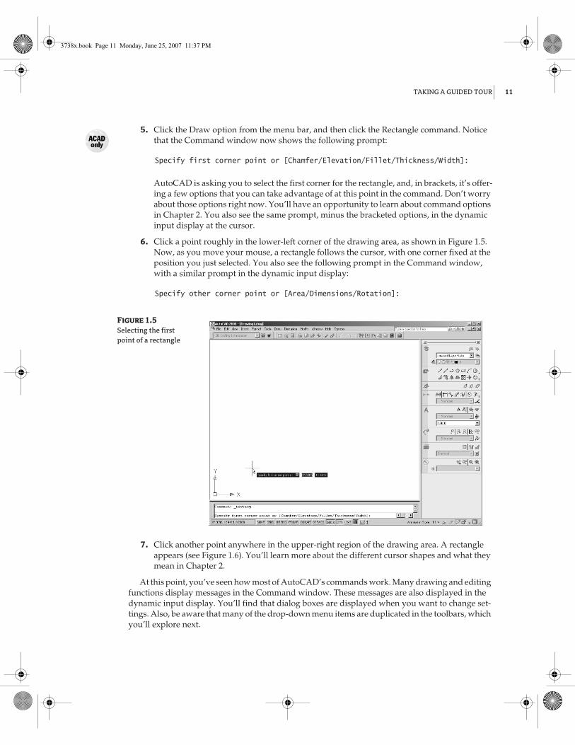
TAKING A GUIDED TOUR
11
5.
Click the Draw option from the menu bar, and then click the Rectangle command. Notice that the Command window now shows the following prompt:
Specify first corner point or [Chamfer/Elevation/Fillet/Thickness/Width]:
AutoCAD is asking you to select the first corner for the rectangle, and, in brackets, it’s offer-ing a few options that you can take advantage of at this point in the command. Don’t worry about those options right now. You’ll have an opportunity to learn about command options in Chapter 2. You also see the same prompt, minus the bracketed options, in the dynamic input display at the cursor.
6.
Click a point roughly in the lower-left corner of the drawing area, as shown in Figure 1.5. Now, as you move your mouse, a rectangle follows the cursor, with one corner fixed at the position you just selected. You also see the following prompt in the Command window, with a similar prompt in the dynamic input display:
Specify other corner point or [Area/Dimensions/Rotation]:
Figure 1.5
Selecting the first point of a rectangle
7.
Click another point anywhere in the upper-right region of the drawing area. A rectangle appears (see Figure 1.6). You’ll learn more about the different cursor shapes and what they mean in Chapter 2.
At this point, you’ve seen how most of AutoCAD’s commands work. Many drawing and editing functions display messages in the Command window. These messages are also displayed in the dynamic input display. You’ll find that dialog boxes are displayed when you want to change set-tings. Also, be aware that many of the drop-down menu items are duplicated in the toolbars, which you’ll explore next.
3738x.book Page 11 Monday, June 25, 2007 11:37 PM

12 CHAPTER 1
EXPLORING THE AUTOCAD AND AUTOCAD LT INTERFACE
Figure 1.6
After you’ve selected the first point of the rectangle, you see a rectangle follow the motion of your mouse.
Communicating with the Command Window and Dynamic Input Display
AutoCAD is the perfect servant: It does everything you tell it to, and no more. You communicatewith AutoCAD by using the drop-down menus and the toolbars. These devices invoke AutoCADcommands. A
command
is a single-word instruction you give to AutoCAD, telling it to do some-thing, such as draw a line (the Line tool in the Draw toolbar) or erase an object (the Erase tool in theModify toolbar). Whenever you invoke a command, by either typing it or selecting a menu or tool-bar item, AutoCAD responds by presenting messages to you in the Command window and thedynamic input display or by displaying a dialog box.
The messages in the Command window often tell you what to do next, or they display a list of options,usually shown in square brackets. A single command often presents a series of messages, which youanswer to complete the command. These messages serve as an aid to new users who need a little help.If you ever get lost while using a command or forget what you’re supposed to do, look at the Commandwindow for clues. As you become more comfortable with AutoCAD, you’ll find that you won’t need torefer to these messages as frequently.
As an additional aid, you can right-click to display a context-sensitive shortcut menu. If you’re in themiddle of a command, this menu displays a list of options specifically related to that command. Forexample, if you right-click your mouse before picking the first point for the rectangle command in theprevious exercise, a menu opens, displaying the same options that are listed in the Command promptplus some additional options.
Finally, the dynamic input display allows you to enter dimensional data of objects as you draw them.Besides echoing the command-line messages, the dynamic input display shows the coordinates andangles of objects you’re drawing and editing. As you enter coordinate or angle values through the key-board, they appear in the dynamic input display. If you’re used to earlier versions of AutoCAD, you caneasily turn off the dynamic input display by clicking the DYN button in the status bar. When thedynamic input display is turned off, your keyboard input appears in the Command window.
3738x.book Page 12 Monday, June 25, 2007 11:37 PM

TAKING A GUIDED TOUR
13
The Dashboard
The menu bar provides most of the commands you need in a format that most Windows users will find easy to understand, and many users are more comfortable using the menu bar. If you prefer using toolbars with their graphic icons, you can start to use the Dashboard. The Dashboard offers many of the same commands as the menu bar but in a more compact format that is quicker to access.
The Dashboard is a collection of lists, buttons, and tools that invoke commands. These tools are grouped into eight
control panels
, each with an icon that shows its function (see Figure 1.7). In typical Windows fashion, each tool offers a
ToolTip
that provides a short description, which helps you under-stand what the icons represent.
Figure 1.7
The control panels of the Dashboard
NOTE
If the Dashboard doesn’t appear on the screen, you can choose Tools �
Palettes �
Dash-board to restore it to the window.
If you move the arrow cursor onto one of the control-panel tools and leave it there for a moment, you’ll see a ToolTip appear just below the cursor. As a new user, you’ll find these ToolTips helpful because they show you the name of the tool. In addition, when I ask you to select a tool, I’ll use the name shown in the ToolTip. For example, if you hover over the icon in the upper-left corner of the Dashboard, you’ll see a ToolTip appear with the name of the control panel, 2D Draw.
Layers
2D Draw
Annotation Scale
Dimensions
Text
Multileaders
Tables
2D Navigate
3738x.book Page 13 Monday, June 25, 2007 11:37 PM
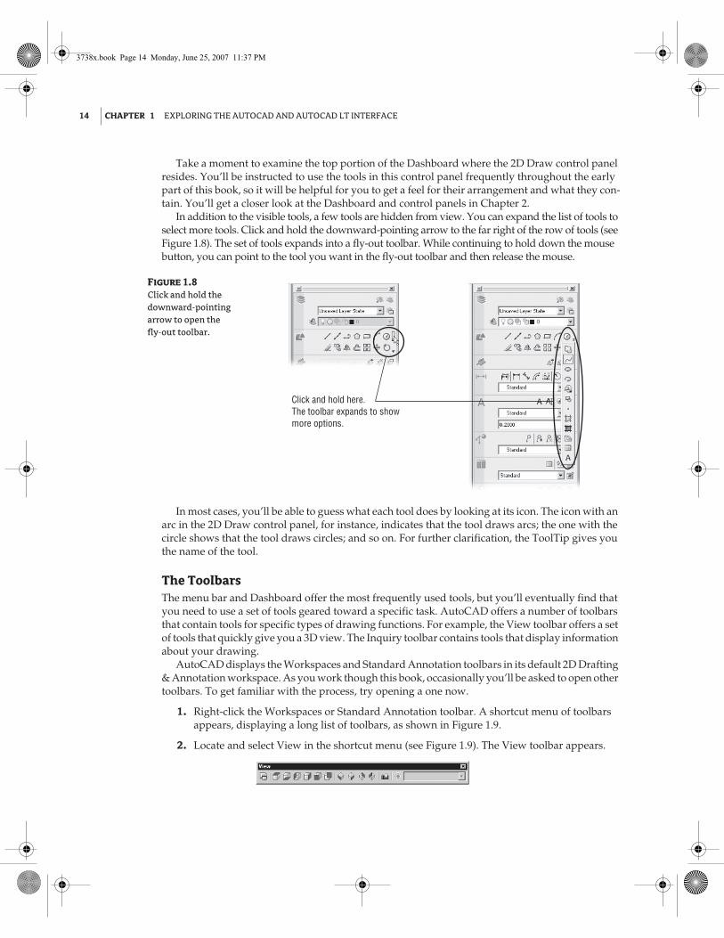
14 CHAPTER 1 EXPLORING THE AUTOCAD AND AUTOCAD LT INTERFACE
Take a moment to examine the top portion of the Dashboard where the 2D Draw control panel resides. You’ll be instructed to use the tools in this control panel frequently throughout the early part of this book, so it will be helpful for you to get a feel for their arrangement and what they con-tain. You’ll get a closer look at the Dashboard and control panels in Chapter 2.
In addition to the visible tools, a few tools are hidden from view. You can expand the list of tools to select more tools. Click and hold the downward-pointing arrow to the far right of the row of tools (see Figure 1.8). The set of tools expands into a fly-out toolbar. While continuing to hold down the mouse button, you can point to the tool you want in the fly-out toolbar and then release the mouse.
Figure 1.8
Click and hold the downward-pointing arrow to open the fly-out toolbar.
In most cases, you’ll be able to guess what each tool does by looking at its icon. The icon with an arc in the 2D Draw control panel, for instance, indicates that the tool draws arcs; the one with the circle shows that the tool draws circles; and so on. For further clarification, the ToolTip gives you the name of the tool.
The ToolbarsThe menu bar and Dashboard offer the most frequently used tools, but you’ll eventually find that you need to use a set of tools geared toward a specific task. AutoCAD offers a number of toolbars that contain tools for specific types of drawing functions. For example, the View toolbar offers a set of tools that quickly give you a 3D view. The Inquiry toolbar contains tools that display information about your drawing.
AutoCAD displays the Workspaces and Standard Annotation toolbars in its default 2D Drafting & Annotation workspace. As you work though this book, occasionally you’ll be asked to open other toolbars. To get familiar with the process, try opening a one now.
1. Right-click the Workspaces or Standard Annotation toolbar. A shortcut menu of toolbars appears, displaying a long list of toolbars, as shown in Figure 1.9.
2. Locate and select View in the shortcut menu (see Figure 1.9). The View toolbar appears.
Click and hold here.The toolbar expands to show more options.
3738x.book Page 14 Monday, June 25, 2007 11:37 PM

TAKING A GUIDED TOUR 15
Figure 1.9
The toolbar shortcut menu
3. You won’t need the View toolbar right now, so go ahead and close it by clicking the X in the upper-right corner of the toolbar.
You may have noticed that the shortcut menu displays a check mark next to the name of a tool-bar that is currently open (see Figure 1.9). You can click a checked toolbar name to close the tool-bar. AutoCAD remembers your toolbar arrangement between sessions. When you exit and then reopen AutoCAD later, the AutoCAD window appears just as you left it.
NOTE If your drawing becomes too cluttered with toolbars, you can drag a toolbar to the border ofthe AutoCAD window, and it will automatically merge with the border. This is called its docked posi-tion. If you don’t want the toolbar to dock but instead want it to appear floating near the border ofthe AutoCAD window, you can do the following: First, change the shape of the toolbar to conformto the orientation of the border. Do this by clicking and dragging the toolbar’s border. Next, pressand hold the Ctrl key as you click and drag the toolbar into position near the border. This preventsthe toolbar from automatically falling into a docked position.
Menus versus the Keyboard
Throughout this book, you’ll be told to select commands and command options from the drop-downmenus and toolbars. For new and experienced users alike, menus and toolbars offer an easy-to-remembermethod for accessing commands. If you’re an experienced AutoCAD user who is used to the earlier ver-sions of AutoCAD, you can type commands directly from the keyboard. Most of the keyboard commandsyou know and love still work as they did.
Another method for accessing commands is to use accelerator keys, which are special keystrokes that openand activate drop-down menu options. You may have noticed that the commands in the menu bar and theitems in the drop-down menus all have an underlined character. By pressing the Alt key followed by the keycorresponding to the underlined character, you activate that command or option without having to engagethe mouse. For example, to choose File � Open, press Alt, then F, and then finally O (Alt+F+O).
3738x.book Page 15 Monday, June 25, 2007 11:37 PM
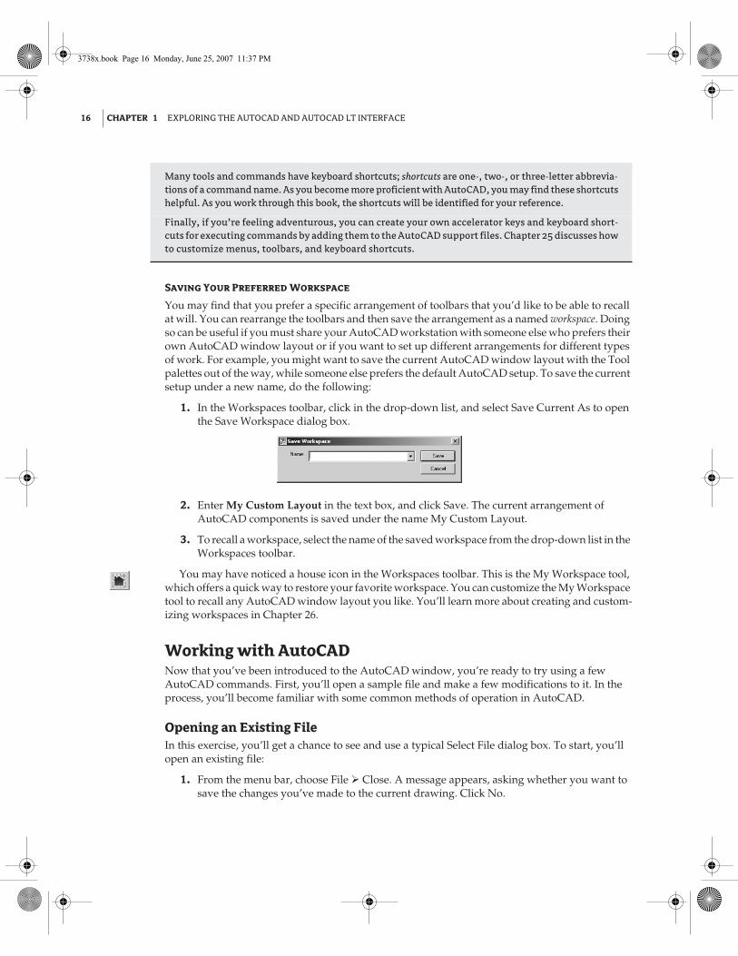
16 CHAPTER 1 EXPLORING THE AUTOCAD AND AUTOCAD LT INTERFACE
Saving Your Preferred Workspace
You may find that you prefer a specific arrangement of toolbars that you’d like to be able to recall at will. You can rearrange the toolbars and then save the arrangement as a named workspace. Doing so can be useful if you must share your AutoCAD workstation with someone else who prefers their own AutoCAD window layout or if you want to set up different arrangements for different types of work. For example, you might want to save the current AutoCAD window layout with the Tool palettes out of the way, while someone else prefers the default AutoCAD setup. To save the current setup under a new name, do the following:
1. In the Workspaces toolbar, click in the drop-down list, and select Save Current As to open the Save Workspace dialog box.
2. Enter My Custom Layout in the text box, and click Save. The current arrangement of AutoCAD components is saved under the name My Custom Layout.
3. To recall a workspace, select the name of the saved workspace from the drop-down list in the Workspaces toolbar.
You may have noticed a house icon in the Workspaces toolbar. This is the My Workspace tool, which offers a quick way to restore your favorite workspace. You can customize the My Workspace tool to recall any AutoCAD window layout you like. You’ll learn more about creating and custom-izing workspaces in Chapter 26.
Working with AutoCADNow that you’ve been introduced to the AutoCAD window, you’re ready to try using a few AutoCAD commands. First, you’ll open a sample file and make a few modifications to it. In the process, you’ll become familiar with some common methods of operation in AutoCAD.
Opening an Existing FileIn this exercise, you’ll get a chance to see and use a typical Select File dialog box. To start, you’ll open an existing file:
1. From the menu bar, choose File � Close. A message appears, asking whether you want to save the changes you’ve made to the current drawing. Click No.
Many tools and commands have keyboard shortcuts; shortcuts are one-, two-, or three-letter abbrevia-tions of a command name. As you become more proficient with AutoCAD, you may find these shortcutshelpful. As you work through this book, the shortcuts will be identified for your reference.
Finally, if you’re feeling adventurous, you can create your own accelerator keys and keyboard short-cuts for executing commands by adding them to the AutoCAD support files. Chapter 25 discusses howto customize menus, toolbars, and keyboard shortcuts.
3738x.book Page 16 Monday, June 25, 2007 11:37 PM

WORKING WITH AUTOCAD 17
2. Choose File � Open to open the Select File dialog box. This is a typical Windows file dialog box, with an added twist: The large Preview box on the right lets you preview a drawing before you open it, thereby saving time while searching for files. To the left is a panel known as the Places List in which you can find frequently used locations on your computer or the Internet.
TIP If you don’t see a Preview box in the Select File dialog box, click the word Views in the upper-right corner, and then select Preview from the list that appears.
3. In the Select File dialog box, open the Look In drop-down list, and locate the 2008acad2008\samplefiles\Mastering AutoCAD 2008\Projects\Chapters 01 folder. (You may need to explore the list to find it.) The file list changes to show the contents of the \AutoCAD 2008\Projects\Chapter 01 folder.
4. Move the arrow cursor to the clip.dwg file, and click it. Notice that the clip.dwg filename now appears in the File Name input box above the file list. Also, the Preview box now shows a thumbnail image of the file. Be aware that files from older versions of AutoCAD may not show a thumbnail.
TIP The clip.dwg drawing is included on the companion website. If you can’t find this file, besure you installed the sample drawings from the companion website. See the Readme file on thebook’s website for installation instructions.
5. Click the Open button at the bottom of the Select File dialog box. AutoCAD opens the clip.dwg file, as shown in Figure 1.10.
The clip.dwg file opens to display a Layout tab view of the drawing. You’ll know this by looking at the tabs at the bottom of the AutoCAD window. Currently, the Layout1 tab is highlighted.
3738x.book Page 17 Monday, June 25, 2007 11:37 PM
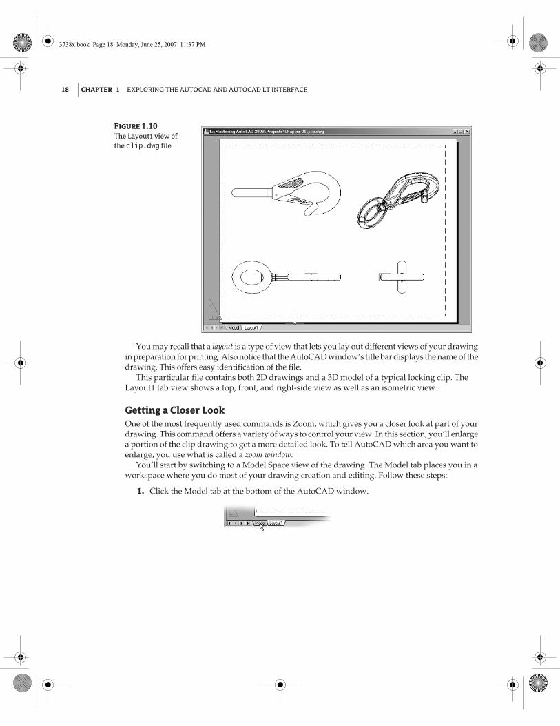
18 CHAPTER 1 EXPLORING THE AUTOCAD AND AUTOCAD LT INTERFACE
Figure 1.10
The Layout1 view of the clip.dwg file
You may recall that a layout is a type of view that lets you lay out different views of your drawing in preparation for printing. Also notice that the AutoCAD window’s title bar displays the name of the drawing. This offers easy identification of the file.
This particular file contains both 2D drawings and a 3D model of a typical locking clip. The Layout1 tab view shows a top, front, and right-side view as well as an isometric view.
Getting a Closer LookOne of the most frequently used commands is Zoom, which gives you a closer look at part of your drawing. This command offers a variety of ways to control your view. In this section, you’ll enlarge a portion of the clip drawing to get a more detailed look. To tell AutoCAD which area you want to enlarge, you use what is called a zoom window.
You’ll start by switching to a Model Space view of the drawing. The Model tab places you in a workspace where you do most of your drawing creation and editing. Follow these steps:
1. Click the Model tab at the bottom of the AutoCAD window.
3738x.book Page 18 Monday, June 25, 2007 11:37 PM
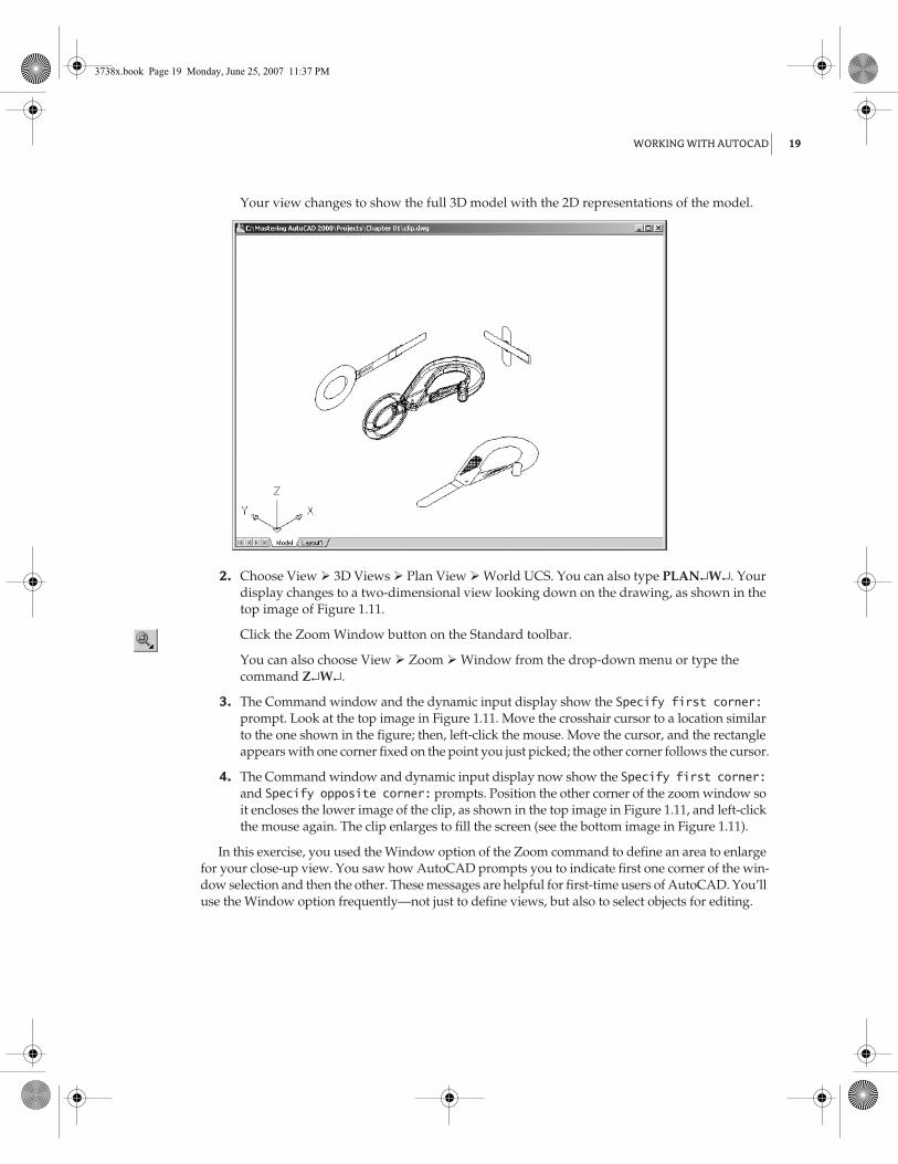
WORKING WITH AUTOCAD 19
Your view changes to show the full 3D model with the 2D representations of the model.
2. Choose View � 3D Views � Plan View � World UCS. You can also type PLAN↵W↵. Your display changes to a two-dimensional view looking down on the drawing, as shown in the top image of Figure 1.11.
Click the Zoom Window button on the Standard toolbar.
You can also choose View � Zoom � Window from the drop-down menu or type the command Z↵W↵.
3. The Command window and the dynamic input display show the Specify first corner: prompt. Look at the top image in Figure 1.11. Move the crosshair cursor to a location similar to the one shown in the figure; then, left-click the mouse. Move the cursor, and the rectangle appears with one corner fixed on the point you just picked; the other corner follows the cursor.
4. The Command window and dynamic input display now show the Specify first corner: and Specify opposite corner: prompts. Position the other corner of the zoom window so it encloses the lower image of the clip, as shown in the top image in Figure 1.11, and left-click the mouse again. The clip enlarges to fill the screen (see the bottom image in Figure 1.11).
In this exercise, you used the Window option of the Zoom command to define an area to enlarge for your close-up view. You saw how AutoCAD prompts you to indicate first one corner of the win-dow selection and then the other. These messages are helpful for first-time users of AutoCAD. You’ll use the Window option frequently—not just to define views, but also to select objects for editing.
3738x.book Page 19 Monday, June 25, 2007 11:37 PM

20 CHAPTER 1 EXPLORING THE AUTOCAD AND AUTOCAD LT INTERFACE
Figure 1.11
Placing the zoom window around the clip
Getting a close-up view of your drawing is crucial to working accurately, but you’ll often want to return to a previous view to get the overall picture. To do so, choose View � Zoom � Previous from the menu bar.
Do this now, and the previous view—the one showing the entire clip—returns to the screen.
Click here for the first corner. Click here for the opposite corner.
3738x.book Page 20 Monday, June 25, 2007 11:37 PM

WORKING WITH AUTOCAD 21
You can quickly enlarge or reduce your view by clicking the Zoom Realtime button in the 2D Navigate control panel. Follow these steps to change your view with the Zoom Realtime button:
1. Click the Zoom Realtime button on the 2D Navigate control panel of the Dashboard.
You can also right-click and choose Zoom from the shortcut menu. The cursor changes to a magnifying glass.
2. Place the Zoom Realtime cursor slightly above the center of the drawing area, and then click and drag downward. Your view zooms out to show more of the drawing.
3. While still holding the left mouse button, move the cursor upward. Your view zooms in to enlarge your view. When you have a view similar to the one shown in Figure 1.12, release the mouse button. (Don’t worry if you don’t get exactly the same view as the figure. This is just for practice.)
4. You’re still in Zoom Realtime mode. Click and drag the mouse again to see how you can further adjust your view. To exit, you can select another command besides a Zoom or Pan, press the Esc key, or right-click your mouse and choose Exit from the shortcut menu.
5. Right-click now, and choose Exit from the shortcut menu to exit the Zoom Realtime command.
Figure 1.12
The final view you want to achieve in step 3 of the exercise
3738x.book Page 21 Monday, June 25, 2007 11:37 PM

22 CHAPTER 1 EXPLORING THE AUTOCAD AND AUTOCAD LT INTERFACE
As you can see from this exercise, you have a wide range of options for viewing your drawings, just by using a few buttons. These buttons are all you need to control the display of 2D drawings.
Saving a File as You WorkIt’s a good idea to save your file periodically as you work on it. As with any Windows program, you can save it under its original name (choose File � Save) or under a different name (choose File � Save As), thereby creating a new file.
By default, AutoCAD automatically saves your work at 10-minute intervals under a name that is a combination of the current filename plus a number and that ends with the .sv$ filename exten-sion; this is known as the Automatic Save feature. Using settings in the Options dialog box or system variables, you can change the name of the autosaved file and control the time between autosaves. See Chapter 3 for details.
TIP By default, in Windows XP, the Automatic Save file is stored in C:\Documents and Settings\User Name\Local Settings\Temp\. You can find the exact location for your system by typingSavefilepathø at the Command prompt. This file location is often set as a hidden folder, so you mayneed to set up Windows Explorer to display hidden folders before you can get to the Automatic Savefile. See Appendix A for information on how to do this.
Making ChangesYou’ll frequently make changes to your drawings. One of AutoCAD’s primary advantages is the ease with which you can make changes. The following exercise shows you a typical sequence of operations involved in changing a drawing:
1. Use the File � Save As menu option to save the current Clip.dwg file under the name MyFirst. For convenience, you can save your files in the My Documents folder.
2. From the 2D Draw control panel, click the Erase tool (the one with a pencil eraser touching paper). This activates the Erase command. You can also choose Modify � Erase from the drop-down menu.
Notice that the cursor has turned into a small square; this square is called the pickbox. You also see Select objects: in the Command window and the dynamic input display. This message helps remind new users what to do.
3. Move the pickbox over the drawing, placing it on various parts of the clip. Don’t click anything yet. Notice that as you hover over objects with the pickbox, they’re highlighted. This helps you see the objects the pickbox is likely to select, should you click the left mouse button.
4. Place the pickbox on the crosshatch pattern of the clip (see Figure 1.13), and click. The cross-hatch changes in appearance from a dark highlight to a light highlight. The pickbox and the Select objects: prompt remain, indicating that you can continue to select objects.
5. Press ↵. The crosshatch disappears. You’ve just erased a part of the drawing.
In this exercise, you first issued the Erase command, and then you selected an object by using a pickbox to click it. The pickbox tells you that you must select items on the screen, and it shows you what you’re about to select by highlighting objects as you hover over them. Once you’ve clicked an object or a set of objects, press ↵ to move on to the next step. This sequence of steps is common to many of the commands you’ll work with in AutoCAD.
TIP You can also click an object or a set of objects and then press the Delete key without using theErase tool.
3738x.book Page 22 Monday, June 25, 2007 11:37 PM

WORKING WITH AUTOCAD 23
Figure 1.13
Erasing a portion of the clip
Opening Multiple FilesYou can have multiple documents open at the same time in AutoCAD. This can be especially help-ful if you want to exchange parts of drawings between files or if you want another file open for reference. Try the following exercise to see how multiple documents work in AutoCAD:
1. Choose File � New to open the Select Template dialog box.
NOTE If you see the Create New Drawing dialog box after step 1, click the Start from Scratch but-ton and select Imperial; then, click OK, and AutoCAD will display a default document. You’lllearn more about the Create New Drawing dialog box in Chapter 2.
2. Make sure acad.dwt is selected, and then click Open.
3. Choose Window � Tile Vertically to get a view of both drawing files. The options in the Window drop-down menu act just like their counterparts in other Windows programs that allow multiple-document editing.
TIP When you create a new file in AutoCAD, you’re actually opening a copy of a template file, asyou saw in step 1. A template file is a blank file that is set up for specific drawing types. Theacad.dwt file is a generic template set up for Imperial measurements. Another template filecalled acadiso.dwt is a generic template useful for metric measurements. Other templates areset up for specific drawing-sheet sizes and measurement systems. You’ll learn more about tem-plates in Chapter 6.
Click here.
3738x.book Page 23 Monday, June 25, 2007 11:37 PM

24 CHAPTER 1 EXPLORING THE AUTOCAD AND AUTOCAD LT INTERFACE
4. Let’s see what can be done with these two files. Click in the window with the clip drawing to make it active.
5. Choose View � Zoom � All to get an overall view of the drawing.
6. Click the 2D version of the clip at the bottom of the drawing to select it. A series of squares and arrows appears on the drawing. These are called grips, and you’ll learn more about them in the next chapter.
7. Click and hold the mouse button on the selected object, but avoid clicking any of the blue squares. Also avoid dragging the object. You’ll see a small rectangle appear next to the cursor.
8. While still holding the left mouse button, drag the cursor to the new file window. When you see the clip appear in the new drawing window, release the mouse button. You’ve just copied part of a drawing from one file to another.
9. This ends the exercises for this chapter. Save the file and then exit AutoCAD.
NOTE You can also use the standard Windows Copy and Paste options (Edit � Copy and Edit �Paste from the menu bar) to copy objects from one window to the other.
Now you’ve had two files open at once. You can have as many files open as you want, as long as your computer has adequate memory to accommodate them. You can control the individual document windows as you would any window, using the Window drop-down menu or the win-dow control buttons in the upper-right corner of the document window.
Adding a Predrawn Symbol with the Tool PaletteIn the preceding exercise, you saw how you can easily copy an object from one file to another by using a click-and-drag method. AutoCAD offers a Tool Palettes window that lets you click and drag predrawn objects into your drawing.
3738x.book Page 24 Monday, June 25, 2007 11:37 PM

THE BOTTOM LINE 25
You can open the Tool Palettes window by clicking the Tool Palettes Window tool in the Stan-dard Annotation toolbar. Once it’s open, you can select a tab containing the predrawn objects you want to use and then click the specific object you want to add. The object appears at the cursor, ready for you to select a location.
In addition to predrawn objects, the Tool palettes offer a way to quickly add fill patterns and other components to your drawing. They’re great tools to help you manage your library of custom, predrawn symbols. Chapter 25 shows you how to use and customize the Tool palettes.
The Bottom LineUsing the AutoCAD Window AutoCAD is a typical Windows graphics program that makes use of menus, toolbars, and palettes. If you’ve used other graphics programs, you’ll see at least a few familiar tools.
Master It Name the components of the AutoCAD window that let you select a function.
Solution AutoCAD offers the menu bar, toolbars, and the Dashboard to give you access to the most common functions.
Getting a Closer Look with the Zoom Command One of the first things you’ll want to learn is how to manipulate your views. The Zoom command is a common tool in graphics programs.
Master It Name two ways of zooming into a view.
Solution Choose View � Zoom � Window, and then click two points to define a zoom window. Another option is to use the Realtime tool in the 2D Navigate control panel.
Saving a File as You Work Nothing is more frustrating than having a power failure cause a loss of hours of work. It’s a good idea to save your work frequently. AutoCAD offers an autosave feature that can be a lifesaver if you happen to forget to save your files.
Master It How often does the AutoCAD autosave feature save your drawing?
Solution Autosave saves a copy of a drawing every 10 minutes by default. This interval can be set by the user.
Making Changes and Opening Multiple Files As with other Windows programs, you can have multiple files open and exchange data between them.
Master It With two drawings open, how can you copy parts of one drawing into the other?
Solution Select the parts you want to copy, and click and hold on any selected part. When you see a small rectangle appear below the cursor, drag the parts into the other drawing. Alternately, you can use the standard Windows Copy and Paste functions.
3738x.book Page 25 Monday, June 25, 2007 11:37 PM

Index
Note to the Reader:
Throughout this index
boldfaced
page numbers indicate primary discussions of a topic.
Italicized
page numbers indicate illustrations.
Symbols
' (apostrophes), 541* (asterisks)
in AutoLISP, 771in calculator, 449in Diesel, 808in layer filters, 153with tables, 331
@ (at signs), 34–35\ (backslashes)
in AutoLISP, 787in macros, 798in menus, 801for spaces, 395
[] <> (brackets)in calculator, 448for default options, 39for linetypes, 813–814
^ (carets)in calculator, 449in menus, 801–802
, (commas)in Cartesian coordinates, 35in hatch patterns, 815in linetype patterns, 812
$ (dollar signs)in Diesel, 804in importing files, 426
" (double quotes)in AutoLISP, 770–771in macros, 765in units, 75
= (equal signs)in AutoLISP, 781in Diesel, 808in filters, 432in tables, 331
! (exclamation points)in AutoLISP, 768in Diesel, 808in filters, 432
> (greater-than symbols)in AutoLISP, 770, 781in Diesel, 808in filters, 432for text, 353–354
< (less-than symbols)for angles, 34in AutoLISP, 781for degrees, 76in Diesel, 808for filters, 432for text, 353–354
- (minus signs)in AutoLISP, 771in calculator, 449in Diesel, 808in linetype patterns, 812for macros, 798with tables, 331in units, 75
() (parentheses)in AutoLISP, 769–772in calculator, 448in Diesel, 805for functions, 763–764in tables, 331
% (percent signs), 311. (periods), 35, 72+ (plus signs)
in AutoLISP, 768, 771in calculator, 449in Diesel, 805, 808in menus, 802with tables, 331
? (question marks)in layer filters, 153for system variables, 541
; (semicolons), 800' (single quotes), 541/ (slashes)
in AutoLISP, 771, 781, 787in calculator, 449in Diesel, 805, 808
for options, 39with tables, 331
_ (underscores)in linetype patterns, 811for text objects, 311
| (vertical bars), 426
Numbers
2D Drafting & Annotation workspace, 6
2D Draw control panelfor tables, 324working with,
27–28
,
29
2D drawings and objects, converting
to 3D forms,
573–579
,
573–579
from 3D models,
259
from 3D views,
590–592
,
591–592
from solids,
708–710
,
709
2D Wireframe option, 587,
587
3 Point UCS tool, 6173D Crosshairs settings,
911
3D drawings and models,
559
.
See also
solids and solid modeling2D drawings from,
259
,
590–592
,
591–592
from 2D shapes,
573–579
,
573–579
aligning objects,
640–642
,
641
configuring,
911–912
,
912
drawing,
568–569
,
569
editing,
593
grips for,
564–566
,
564–565
hidden lines, 708moving objects,
642
,
642
Osnaps,
568
point filters for,
580
,
581
pushing and pulling shapes,
569–570
,
569–571
rendering.
See
rendering 3D models
3738x.book Page 957 Monday, June 25, 2007 11:37 PM
COPYRIG
HTED M
ATERIAL
958
3D FACES • ALIASES
rotating objects,
566–568
,
566–567
,
643
,
643
, 713–714,
714
solids for,
562–563
,
562
Sweep for,
625–632
,
625–632
viewing,
581–585
viewports for,
609–612
,
609–612
visual effects,
586–590
,
586–590
workspace for,
559–562
,
560–562
3D Facesconverting solids to, 724restrictions on, 616with UCS, 606
3D forms, laying out,
613–614
,
613–614
3D Graphics System Configuration dialog box,
917–919
3D Hidden option, 2483D Make panel, 561,
561
, 598,
598
3D Modeling tab,
911–912
,
912
3D Modeling workspace, 6,
6
3D Move tool, 642,
642
3D Navigate panel, 561,
561
, 652–653, 659
3D Navigation settings, 911–9123D Objects settings, 9113D Orbit tool, 624, 9173D polylines,
615–616
,
616
3D Section option, 7363D surfaces.
See
surfaces3D Wireframe option
Visual Styles, 586–587,
587
volume of cuts, 635,
635
3Darray command,
644
3Dmirror command,
644
3DPerformance settings,
905
3points slice option, 716
A
About option, 64Above Dimension Text
option, 946Abs function, 445, 449ACAD_ linetypes,
154
Acad.dwt file, 23, 291Acad.fmp file, 314Acad.lin file, 154, 810–811
Acad.pat file, 815Acad.pgp file, 752Acad.psf file, 898acad3D.dwt template, 559, 564AcadCAD log file, 159acadiso.dwt file, 23Acadiso.lin file, 154acceleration, hardware, 918accelerator keys, 15
keyboard, 10, 87,
751–752
,
751
settings for, 907troubleshooting, 936
on menus,
802–803
,
803
acos function, 449actions for dynamic blocks
adding,
480–482
,
481–482
for arrays, 504–505,
504–505
editing,
484
scale and stretch,
486–490
,
487–489
Activate Live Sectioning option, 732
active viewports, 458, 460Adaptive Degradation And
Performance Tuning dialog box3D performance, 905,
917–919
,
917
driver updates, 921Adaptive option, 279Add-A-Plot Style Table wizard,
262, 281, 283Add-A-Plotter Wizard,
255–257
,
256
, 261, 548Add a Printer option, 255Add Color-Dependent Plot Style
Table Wizard, 270Add Current Scale tool, 294Add Custom Property dialog box,
879,
879
Add File button, 820Add function, 808Add Jog To Section option, 734Add New Location listing,
864, 870Add options
groups, 131selecting objects, 48spline curves, 527
Add Or Configure Plotters option, 256, 261
Add Or Edit Plot Style Tables option, 262
Add Parameter Properties dialog box, 493,
493
, 495Add Plot Style dialog box, 283Add Printer Wizard, 255Add Profile dialog box, 914Add/Remove selection mode, 94Add Scale dialog box, 247,
247
Add Scales To Object dialog box, 124,
124
Add: Select Objects button, 216Add Sheets tool, 829,
829
Add Standards File button, 850Add Style option, 280Add To Dictionary option, 313Add To Favorites tool, 839Add To Group option, 132Add To History option, 762Add To List option, 914Add To Working Set tool, 236addition
areas,
536–538
,
536
,
538
AutoLISP, 770–771calculator, 449Diesel, 805in tables, 331–332
Additional Angles settings,
80
Additional Resources option, 64Additional Settings dialog box,
400,
400
Adjust Background Image dialog box, 661,
661
Adjust Bitmap dialog box, 679Adjust Display Scale option, 470Adjust Exposure tool, 684Adjust Image button, 661Adjust Rendering Exposure
dialog box, 684, 699,
699
Adjustment option, 279ADT (Architectural Desktop
2008),
933–934
Advanced Options dialog box, 929,
929
Advanced Render Settings option, 683
Advanced Render Settings palette, 696–697,
696
Advanced tab in DesignCenter searches, 842
After Primary Value option, 952AGP Bus, 921Al command, 640aliases, command,
751–752
,
751
3738x.book Page 958 Monday, June 25, 2007 11:37 PM

ALIGN OPTION • ARGUMENTS
959
Align option, 310,
310
Align tool, 640Align Space tool, 758Aligned tool, 363Aligned With Dimension Line
option, 342, 947aligning
dimensions, 363,
364
, 947multileader notes, 373objects
in 3D space,
640–642
,
641
with layout objects,
758–759
,
759
with Osnap tracking,
97–102
,
98–102
with Sweep, 628,
628
text,
301–302
,
301
,
309–310
,
309–310
, 327,
327
viewports,
759–761
,
760
Alignment option, 628,
628
Alignment Point Acquisition option, 910
All optionsselecting objects, 48zooming, 198, 200
All Borders option, 330All Cross Sections option, 638All Used Layers option, 148, 150Allow Exploding option, 110Allow Long Symbol Names
option, 906Allow Other Users To Refedit
Current Drawing option, 232, 904
Allow reverse Lookup option, 494Alt key for accelerator keys, 15alternate dimensions, adding and
removing,
362–363
alternate units,
346
,
346
Alternate Units tab, 346,
346
, 362,
951–952
,
951
Always Keep Text Between Ext Lines option, 948
American Institute of Architects layer naming convention, 152–153
AND operationsAutoLISP, 782grouping, 433searches, 63
Ang function, 445Angbase system variable, 75
Angdir system variable, 75Angle function,
783
Angle Of Line Defined By Two Points tool,
436
, 437, 439,
439angles
arcs, 40, 40circular copies, 168dimension lines, 365, 368, 368dimension text, 355, 358dimensions for, 365–367, 365direction for, 73–74, 73falloff, 670–671, 670–671hatch patterns, 207, 815linetypes, 813with Loft, 639, 640moving objects, 46–48multileaders, 370Polar Tracking, 79, 80precision for, 73QuickCalc calculator for,
437–439, 437–439revolving polylines, 713row and column copies, 169shapes, 755specifying, 34, 35styles for, 74–75text, 296, 296, 308units for, 76Xlines, 190
Angtos function, 785Angular tool, 365animation
settings, 912walk-throughs, 690–692, 690
Animation Preview window, 691Animation Settings button, 912Annotation Object Scale dialog
box, 123–124, 123annotation scale, 122–125,
123–125, 294–295Annotative option
blocks, 110hatch patterns, 217scales, 948
ANSI format, templates for, 164Aperture Size option, 910apostrophes ('), 541Apparent Intersection Osnap
option, 95Append to Current Selection Set
option, 435
Application Data folders option, 919
Apply Changes To Existing References option, 397
Apply Global Scale Factor to Non-ISO Linetypes option, 278
Apply Material To Objects tool, 657, 657, 678
Apply Selected Visual Style To Current Viewport tool, 588, 588
Apply Solid Fill option, 510, 902Apply To option, 435Apply To All Active Viewports
option, 604Apply To Layout Dimensions
Only option, 473, 730, 950Ar command, 385Arc And Circle Smoothness
option, 156, 901Arc tool, 29, 39, 89, 89Arc Length tool, 368Architectural Desktop 2008
(ADT), 933–934Architectural units, 73–74Archive A Sheet Set dialog box,
890–891, 890archiving sheet sets, 889–891,
890–891arcs, 88–93, 90–91
dimensions, 365–368, 946distances along, 191–192,
191–192length, 192, 368moving, 50options, 38–42, 40–42for polylines, 508, 509properties, 67–68, 67smoothness, 651, 901with UCS, 605
Area command, 534–538Area Fill Correction option, 924area of objects, 534–535
complex, 536–538, 536, 538hatch patterns for,
535–536, 536Area system variable, 541Area tool, 534argument lists, 765arguments
AutoLISP, 770–771Diesel, 805functions, 765
3738x.book Page 959 Monday, June 25, 2007 11:37 PM
960 ARRAY COMMAND • AUTODESK DWF VIEWER
Array command, 166–167, 169, 593
Array dialog box, 167, 167, 385, 385
Array tool, 29, 167, 169, 385arrays, 165–166
for 3D objects, 5933Darray for, 644actions for, 504–505, 504creating, 385polar, 166–168, 167–169rectangular, 169–173, 169–173
Arrowhead panel, 371arrows
blocks for, 954–955, 955notes with, 369–372, 369options for, 945styles for, 342–345, 343–344
Arrows option, 948As Displayed option, 248, 731ASCII files, importing, 306–307asin function, 449assembling
cross-references, 420–424, 420–424
parts, 197–200, 198–200assigning layers, 140–142, 745–746Associate Hyperlink option, 888associating
standards, 850–851, 850text with drawing properties,
319–323, 320–322associative dimensioning, 337,
360–361, 361options, 909Paper Space, 471–473, 472updating, 473
associative hatch patterns, 214, 222, 913
asterisks (*)in AutoLISP, 771with calculator, 449in Diesel, 808in layer filters, 153with tables, 331
at signs (@), 34–35atan functions, 449, 772Ate command, 392Atof function, 785Atoi function, 785atom operator, 781atoms in AutoLISP, 769
Att command, 384Attach By Layer tool, 664, 664Attach Digital Signature After
Saving Drawing option, 825Attach Digital Signatures dialog
box, 826–827, 826Attach external reference
option, 229Attach Xdata tool, 756Attach Xref tool, 420–421, 420attaching
data to objects, 756external files, 225–227,
225–227Attachment option, 230Attdia system variable, 388Attdisp command, 394Attedit command, 393, 395attenuation properties for
lights, 671Attredef command, 398Attribute Definition dialog box,
384–385, 384modes, 387view labels, 883–884, 883
Attribute Extraction - Refine Data dialog box, 496, 497
Attribute Extraction - Select Attributes dialog box, 496, 497
Attribute Extraction Wizard, 398–399, 496, 497
Attribute tabEdit Attribute, 396, 396Enhanced Attribute Editor,
392–393, 393attributes, 381
areas, 539with blocks
adding, 382–385, 383–384inserting, 388–390,
389–390redefining, 397–398
copying and editing, 385–388, 385–386
creating, 381–382, 382definitions for, 385–388,
385–386editing, 391–398, 391–393,
396–397exporting, 398–404extracting, 398–404, 494–497,
495–497
global changes to, 393–397, 396–397
invisible, 394–395, 395prompts for, 384, 386with UCS, 606
Attsync command, 397Audit option, 545audit report files, 851–853AUGI (Autodesk User Group
International) option, 64Aunits system variable, 74Auprec system variable, 74authors, storing information
on, 544Auto selection option, 50AutoCAD 2008 Developer Help
window, 787AutoCAD 2008 Help dialog box
Contents tab, 62, 62for context-sensitive help, 64
AutoCAD 2008 Master Setup dialog box, 896
AutoCAD 2008 Support folder, 846
AutoCAD Alias Editor dialog box, 751, 751
AutoCAD Classic workspace, 559AutoCAD DesignCenter, 109,
836–839, 837–838exchanging data between files
with, 843loading files into, 843–844opening and inserting files
with, 840searching and extracting
drawing contents with, 840–842, 840
for symbols, 844for Tool Palettes, 844–848, 847
AutoCAD Entities OLE option, 554
AutoCAD fonts, 305, 306AutoCAD Text Window, 66, 66,
158, 543AutoCAD window, 4, 4
components, 6–8, 6–7workspace selection in, 5, 5
Autodesk AutoCAD Certified Hardware XML Dataspace page, 921
Autodesk Developer Center, 64Autodesk DWF Viewer, 830, 830
3738x.book Page 960 Monday, June 25, 2007 11:37 PM

AUTODESK TRAINING SITE • BLOCKS 961
Autodesk Training site, 64Autodesk User Group
International (AUGI) option, 64AutoFit option, 333AutoLISP program, 761, 767
arguments, 770–771control structures, 780–783data types, 769–770expressions, 767, 770–771functions, 770–772
data type conversion, 785–786
geometric, 783–784string, 784
interpreter for, 767–768keyboard macros with,
763–765, 764lists, 775–776loading and running
programs, 761–763, 761sample program, 773–778,
774, 778saving programs, 786–787selecting objects, 778–780for submenus, 802user input, 775–778, 778variables, 768–772, 769
automatic operationsOLE link updating, 553saving, 22, 903
Automatic Save option, 903Automatically Select All Nested
Objects option, 236Autoselect feature, 51–52AutoSnap feature, 910AutoSnap Marker Color
option, 92AutoSnap Marker Size option, 92Autospool feature, 256, 923Available Materials In Drawing
panel, 655Average function, 331axes
Dynamic UCS, 566ellipses, 81in rotating, 607–608
BBack Orthogonal views, 581, 582Back UCS orientation, 598, 599
background colorplot preview, 930–931Windows metafile, 931
Background dialog box, 660, 660background grids
Grid mode as, 102–104information on, 540
background plots, 262Backgroundplot system variable,
250, 262backgrounds
in Layout tabs, 252, 252rendering 3D models,
659–661, 659–661text, 746
backslashes (\)in AutoLISP, 787in macros, 798in menus, 801for spaces, 395
Backspace key, 33backwards text, 296.bak extension, 933base angles, 75Base Point Parameter tool, 479base points
blocks, 108with inserting symbols,
116–117, 158for selecting objects, 44–48,
46–47with stretching, 55for Sweep, 628, 629
Baseline option, 351–352Baseline Spacing option, 945baselines, dimensions from,
351–352, 352batch plotting
sheet sets, 891–892, 891working with, 264
Batch Standards Checker, 851–853, 851–852
Batting linetype, 154BC text option, 310Beep On Error In User Input
option, 906Begin grouping operator, 433Below Primary Value option, 952Beside The Dimension Line
option, 347, 948Binary option for .dxf files, 547
Bind External Reference option, 229, 822
bisecting Xline angles, 190bitmap images
in 3D models, 671for buildings, 672–673,
672–673materials to fit objects,
673–676, 674–675size, 676–679, 677–679
brightness, contrast, and strength, 411–413, 411, 413
clipping, 410–411, 412exporting, 548–549, 548frames for, 413–415, 413importing, 406–408, 406–408plotting, 259quality, 413–415, 413transparency, 415visibility, 409–410
Bitmap OLE option, 554BL text option, 310Blipmode system variable, 37,
534–535blips, 37, 937Block Attribute Manager dialog
box, 396–397, 397Block Authoring palettes,
476–477, 476Block Definition dialog box,
108–111, 108, 123, 123, 387–388, 885
Block Editor, 475–478, 476–478Block Editor tool, 478Block Editor toolbar, 476–477,
476–477Block Units option, 111blocks
adding and removing objects, 234–236, 235–236
annotation scale, 122–125, 123–125
for arrowheads and tick marks, 954–955, 955
from attribute definitions, 387–388
with attributesadding, 382–385, 383–384inserting, 388–390,
389–390redefining, 397–398
3738x.book Page 961 Monday, June 25, 2007 11:37 PM
962 BLOCKTOXREF DIALOG BOX • CENTER OPTIONS
dynamic. See dynamic blocksediting, 475–478, 476–478exploding, 118–119Express Tools for, 747–748vs. external references, 224,
227–228with frozen layers, 205–206inserting, 111–115, 112–113,
212–213, 388–390layers for, 142–143listing, 158–159log files for, 159as markers, 530moving, 117, 117names for, 120, 213, 236–237nesting, 212purging, 194–195, 195redefining, 118–119replacing, 120–121saving, 120scaling, 908shapes for, 754–756, 755with sheet sets, 876–882,
877–879substituting, 213for symbols, 107–109with UCS, 606unblocking, 118–119updating, 212–213, 213
BLOCKTOXREF dialog box, 748, 748
.bmp files. See bitmap imagesBold tool, 299Boolean operations, 63,
703–705, 705BORDER linetypes, 154borders
tables, 328–329, 328–329, 336viewports, 460
Both Text and Arrows option, 948Bottom Orthogonal views,
581, 582Bottom UCS orientation, 598Boundary command, 536–537Boundary Creation dialog box,
537, 537Boundary Set options, 219, 221boundary windows, 290, 290,
297, 297Box Mapping tool, 673Box options for selecting, 48Box tool, 563
boxes, 703, 704buildings from, 672–673,
672–673creating, 563–564, 563
BR text option, 310brackets ([] <>)
in calculator, 448for default options, 39for linetypes, 813–814
Break at Point tool, 29, 144, 144Break Link option, 553Break tool, 29, 516breakat macro, 763–765, 764breaking
keyboard macro for, 763–765, 764
lines, 144objects, 184, 184polylines, 516vertices, 516, 516
brightness of raster images, 411–413, 411, 413
Browse external reference option, 230
Browse feature in DesignCenter searches, 841
Browse The Web dialog box, 835Browse The Web-Select
Hyperlink dialog box, 833Browse To Another Sheet Set To
Use As An Example option, 867Browsed Pages option, 835bump maps, 683, 683Button Editor dialog box,
799–800, 799Button Image group, 795, 795, 799buttons
creating, 797–798, 797–798icons for, 799–800, 799
By Object option, 655ByBlock color assignment, 159ByLayer color assignment,
159, 855
CC command, 167Cache Model Tab And All
Layouts option, 906Cache Model Tab And Last
Layout option, 906
calculator. See QuickCalc calculator
Calibrate Plotter wizard, 926, 926calibration options, 926–927, 926callout blocks, 867
creating, 887–889, 887–888as cross-reference symbols,
872–874, 873Camera Glyph setting, 685Camera Preview dialog box,
687–688, 687cameras
adjustments for, 687–689, 687–689
for view changes, 583–584, 584
for view control, 684–687, 685–687
Cancel option for OLE link updating, 553
canceling commands, 33capturing Text Window
information, 543carets (^)
for calculator, 449in menus, 801–802
Cartesian coordinates, 34–36, 35–36
cascading menus, 10case sensitivity in AutoLISP, 773Cell Border Properties dialog box,
328–330, 328Cell Borders menu, 328Cell Margin option, 327Cell Styles settings, table
styles, 335cells
array, 170–171, 171table, 323, 323
formulas in, 330–331, 330–331
graphics for, 333, 333text in, 324–325, 324–326
Celtscale system variable, 160CENTER linetypes, 154Center Mark tool, 366center marks, 945Center options
arcs, 39gradients, 221Osnaps, 95, 385text, 309
3738x.book Page 962 Monday, June 25, 2007 11:37 PM

CENTER POINT OPTION • COMMANDS 963
Center point option, 167Center Running Osnaps dialog
box, 514Center tool for text, 299centering objects, 485–486, 485Cha command, 717Chain option, 485Chamfer command, 180Chamfer tool, 29, 717chamfering, 718, 718Change All spelling checker
option, 312–313Change Dictionaries dialog
box, 312Change Link dialog box, 553Change option for spelling
checker, 312–313Change Page Setup option, 829Change Source OLE option, 553Change To Current Layer tool,
745, 746Change URLs option, 758Character Map dialog box, 300,
300, 312Check All Drawings Using The
Following Standards Files option, 852
Check Each Drawing Using Its Associated Standards Files option, 852
Check For New Content option, 66
Check For Updates option, 917, 921
Check Spelling dialog box, 312–313, 312
Check Standards button, 850Check Standards dialog box,
850–851Check Web For Live Enablers
option, 907Checkered Underlay On option,
656, 656Choose Layouts page, 860, 860Choose Output screen, 402, 402chord length, 40.chx files, 853Circle tool, 29, 167circles
on 3D surfaces, 568–569, 569drawing, 166–167, 167–169smoothness, 651, 901
with UCS, 605for viewports, 466–467, 467
circular copies, 166–168, 167–169Clean tool, 725cleaning up
lines, 179–182, 180–182screen, 37
Clear tool, 436, 436Clear History tool, 436, 436Click To Set New Origin option,
210–211clicking, 8clip.dwg file, 17, 18Clip Existing Viewport tool, 466Clip Image option, 411clip limits, 263, 263Clipboard
exporting data, 555importing data, 551Text Window
information, 543clipping
Extended Clip for, 752, 753raster images, 407,
410–411, 412Clipping option, 687–688clipping planes, 688–689, 688clipping views, 230–231, 231Close All Drawings option, 758close objects, selecting, 450Close options
polylines, 509, 512spline curves, 526–527
Close Sheet Set option, 875Close Solid option, 640Close Surface option, 640close-up views. See zoomingclosing
lines, 35sheet sets, 875–876
Cloud tool, 29Co command, 87codes for special characters, 311color book location, 138–139Color Books tab, 138–139, 138Color Depth option, 925Color Faces tool, 724, 724Color option
Flatshot, 592interference, 625Osnaps, 910
Color Options dialog box, 930color plot styles
converting to named plot styles, 286
tables, 267–270Color tool, 299colors
acad3D.dwt template, 564AutoCAD window, 901AutoSnap markers, 92blocks, 142–143borders, 460dimension text, 946dimensions, 943Dynamic UCS axes, 566extension lines, 945Flatshot, 592gradients, 219–221, 220grips, 53layers, 137–139, 137–138,
145, 147materials, 655Osnaps, 910plot styles, 273–275, 274–275surfaces, 724text, 299
Colors setting, 901columns
layer lists, 139tables, 323–324, 323, 326–327text, 299
Columns tool, 299Command Alias Editor, 751–752command function, 765, 779–780command line
Diesel at, 805–806pasting to, 443, 443for solids editing, 725
Command List, 795Command window, 6, 7, 37
communicating with, 12description, 9moving and sizing, 7
commands, 12canceling, 33help for, 62–66, 62–63, 65history, 66, 66in menus, 9–11QuickCalc calculations in,
446–447toolbars for, 14–16
3738x.book Page 963 Monday, June 25, 2007 11:37 PM

964 COMMAS • CORNER DECELERATION OPTION
commas (,)in Cartesian coordinates, 35in hatch patterns, 815in linetype patterns, 812
common base extension lines, 351–352, 352
Communication Center, 65–66, 65Compare Dimension Styles dialog
box, 942–943, 943Compare option for
dimensions, 942comparison operators in
filters, 432complex linetypes, 813–815complex objects, area of, 536–538,
536, 538composite external references,
420–424, 420–424composite solids, 705concatenation, 771Conceptual option, 587, 587cones, 703, 704Configure Standards dialog box,
850, 850configuring, 896–897
3D graphics system, 917–919, 917
3D modeling, 911–912, 912display options, 900–902, 900drafting, 909–911, 909DWF format files, 832files, 897–900, 897Grips feature, 916interface settings,
905–907, 905noun/verb selection
method, 916opening and saving,
902–904, 902plotters, 258–259, 258
DWF format files, 831–832, 832
raster files, 548–549, 548profile options, 914–915, 914selections, 912–914, 912tablet menu area, 915–916, 915Tracking Vector, 916–917user preferences, 907–909, 907
Confirm Purge dialog box, 195, 225
Constant attribute option, 387
Constrained Orbit tool, 582–583, 582
constraining motion, 565–566, 565Constraints panel, 372Construction Line tool, 29,
187, 187construction lines, 185–191,
185–186, 188–190Containing option, 842Containing Text option, 842Content tab, 372Content type option, 370Contents tab, 62, 62context sensitivity, 8
help, 64menus, 12
Context window, 316Continue option, 351continuing dimensions,
350–351, 350contour lines, 513–514, 513Contour Lines Per Surface option,
711, 901contrast of raster images, 411–413,
411, 413control panels, 13, 13, 560–561, 561control points, 526–528control structures in
AutoLISP, 780If...Then...Else, 780–782loops, 782–783
conventional memory, information on, 540
Convert Block To Xref tool, 748Convert Object To Viewport
tool, 466Convert PLT to DWG tool, 757Convert Shape To Block tool, 747Convert To Block option, 110Convert To Grayscale option, 279Convert To Group Filter
option, 152Convert To Solid tool, 579, 579,
598, 602Convert To Surface tool, 579Convertctb command, 286converting
2D shapes to forms, 573–579, 573–579
3D drawings to 2D views, 2593D views into 2D drawings,
590–592, 591–592
AutoLISP data types, 785–786color plot styles to named plot
styles, 286layer settings, 853–855,
854–855objects with thickness into
solids, 578–579, 578–579, 602
polylines, 514–515QuickCalc calculator for,
440–441, 441surfaces to solids, 621
Convertpstyles command, 286convtosolid command, 579, 602coordinate data entry, priority
for, 908coordinate readouts, 8
drawing area size, 76Polar Snap mode, 78–79
coordinatesAutoLISP, 774, 774for distances, 32–36, 34–36hatch patterns, 816, 816QuickCalc calculations, 447spherical and cylindrical,
614, 615Copy command, 543, 593Copy Edges tool, 724, 724Copy Faces tool, 724, 724Copy History command, 543Copy Link command, 555Copy Nested Objects tool, 747Copy Objects To New Layer tool,
746, 746Copy Render Presets dialog
box, 698Copy Selected Sheets option, 830Copy tool, 29, 82, 82, 128copying
attributes, 385–388, 385–386circular, 166–168, 167–169faces and edges, 725with grips, 56, 56lines, 82, 82offsets for, 87–88polylines, 510, 510rows and columns, 169–173,
169–173Text Window
information, 543cord length, 40Corner Deceleration option, 692
3738x.book Page 964 Monday, June 25, 2007 11:37 PM
CORNER STYLES • DATE AND TIME FIELD 965
corner styles, plot style tables for, 275–276
cornerschamfering, 718, 718rounding, 716–717, 716
corrupted file recovery, 545, 935cos function
AutoLISP, 772calculator, 449
Count function, 331CRC (Cyclic Redundancy Check)
validation option, 903Create A Distance Light tool, 652Create A Point Light tool, 668Create A Spotlight tool, 666Create Backup Copy with Each
Save option, 903, 933Create Camera tool, 686, 686Create DXF File dialog box, 547Create Group options, 131Create Group tool, 127Create New Dimension dialog
box, 941–942, 941Create New Dimension Style
dialog box, 340, 340Create New Drawing dialog box,
23, 98, 98import settings, 174named plot styles, 280
Create New Folder tool, 821Create New Material dialog box,
657, 662Create New Material tool, 657,
662, 677Create New Table Style dialog
box, 334, 334Create New Visual Style dialog
box, 588, 588Create New Visual Style tool,
588, 588Create Or Append Linetype File
dialog box, 811Create Separate Hatches
option, 217Create Sheet Set Wizard, 859–861,
859–861, 867–868Create Subsets Based On File
Structure option, 862Create Transmittal dialog box,
820–821, 820Create Unique Layer, Style, And
Block Names option, 236–237
criteria for object filters, 432–433cross-referenced drawings. See
external referencesCross Section Only option, 637cross sections with Loft, 637–639,
637, 639crosshair cursor, 38, 902, 911Crosshair Labels option, 911Crossing Polygon selection
option, 48Crossing Polygon windows, 359Crossing selection option, 48crossing windows, 48–52, 51–52,
358–359, 359.csv extension, 333.ctb files, 268, 286Ctrl key in accelerator keys, 802CUI (Custom User Interface),
791–794, 792–794Cuiload command, 804Cur function, 445current layers, 143Current Viewport option, 219, 611current viewports, 458CurrentSheet options, 882cursor, 8cursor modes, 37–38, 38curved 3D surfaces, 616–620,
617–620curves
distances along, 191–192, 191–192
divisions on, 528–530, 529extrusions on, 711–712,
711–712NURBS, 81, 525parallel, 510, 511with Sketch, 531spline. See spline curves
Curves tessellation option, 919.cus extension, 313Custom option for shaded
viewports, 248Custom Paper Size wizard,
549, 927custom properties, options
for, 925Custom Properties dialog box,
878–879Custom setup option, 896custom spelling dictionaries, 313
Custom tabdrawing information, 544hatch patterns, 217
Custom User Interface (CUI), 791–794, 792–794
Customize dialog box, 847–848, 847
customizing AutoCAD. See also configuring
Command List for, 795with Express Tools. See
Express Toolshatch patterns, 815–817,
815–817linetypes, 810–815macros, 800–802, 801–802menus, 796–797saving and loading
customizations, 803–804, 804
sheet sets, 876–889, 877–879, 883–888
toolbars, 796–800, 798–799user interface, 791–794,
792–794workspaces, 789–791, 790
cuts, volumes of, 635–637, 635–637
cylinders, 703, 703–704cylindrical coordinate format,
614, 615
Dd codes for degrees, 75, 311D command, 339, 362d2r function, 449Dal command, 363Dan command, 365dash-dot lines, 154Dashboard, 7
for 3D drawings, 560–561, 561, 595, 596
working with, 13–14, 13–14DASHDOT linetypes, 154DASHED linetypes, 154dashes (-). See minus signs (-)Data Extraction Wizard, 399–403,
399–403data types in AutoLISP, 769–770databases, inserting, 550Date and Time field, 880
3738x.book Page 965 Monday, June 25, 2007 11:37 PM

966 DATE MODIFIED TAB • DIGITAL SIGNATURES
Date Modified tab, 842Date option for external
references, 229dates of external reference
files, 229Dba command, 351dbConnect feature, 906DC Online tab, 844Dco command, 350.dct extension, 313Dctmain system variable, 313Ddatte command, 539Ddi command, 365Decimal measurement system, 74Decimal Places Of Accuracy
option, 547decimal points, 35, 72Decimal Separator option,
341, 950Ded command, 355, 368Default drop-down list, 470Default To Boundary Extents
option, 210defaults
attributes, 386line weights, 470options and settings, 39plotting, 261, 928
Define Data Source dialog box, 399, 399
Define Window button, 203defining
attributes, 384–385UCS, 596–599, 597–599views, 203
definition points for dimensions, 354–356, 355
Defpoints layer, 356defragmented hard disk
space, 931Defun function, 763–765, 764,
773, 775Degrade When Fps Is Below
setting, 917degrees and degree signs, 75, 311Delete Columns option, 328Delete Faces tool, 720, 720Delete Interference Objects
Created On Close option, 624, 636
Delete Layer button, 139, 139
Delete optionslayer settings, 430profiles, 914
Delete Output File option, 684Delete Rows option, 328Delete Style option, 280deleting. See also erasing
alternate dimensions, 362–363attributes, 397blocks, 194–195, 195columns, 328control points, 527external reference objects,
234–236, 235–236group object members, 132hyperlinks, 835layer settings, 430layers, 139, 151profiles, 914rows, 328scale list items, 247sliced objects, 715surfaces, 720text styles, 295tools, 793
DElta option, 193Demand Load ObjectARX
Applications option, 904Demand Load Xrefs option, 904demand loading, 230–231, 904Description option
blocks, 111Form View tab, 279
Description tool, 839descriptions
buttons, 798groups of objects, 130–131linetypes, 811profiles, 914
Deselect Group option, 133deselecting objects, 43DesignCenter, 109, 836–839,
837–838exchanging data between files
with, 843loading files into, 843–844opening and inserting files
with, 840searching and extracting
drawing contents with, 840–842, 840
for symbols, 844for Tool Palettes, 844–848, 847
DesignCenter folder, 838, 838DesignCenter window,
837–838, 838desktop publishing
exporting raster files for, 548–549, 548
exporting vector files for, 550–551
Detach external reference option, 229
Details optionexternal reference, 229groups, 133
Device And Document Settings tab, 923–924, 924
calibration, 926–927, 926custom properties, 925DWF format files, 832, 832graphics, 925initialization strings, 925media, 924merge control, 929, 930paper sizes, 927, 927, 930pens, 924–925plotters, 258–259, 258saving and importing, 928
device drivers, paths for, 898Di command, 74dialog boxes, 10diameter dimensions,
365–367, 366Diameter tool, 365dictionaries
location, 898spelling checker, 312–313
Diesel programming language, 804–805
at command line, 805–806for menu option labels,
807–808for menus, 806for text, 809
Diffuse settings, 655Diffuse map setting, 658–659, 658Digital Signature Contents dialog
box, 825, 825Digital Signature tab, 825, 825, 827digital signatures, 824–827,
825–827
3738x.book Page 966 Monday, June 25, 2007 11:37 PM

DIGITIZERS • DIMLWD DIMENSION VARIABLE 967
digitizers, 406digitizing tablets, 922Dimadec dimension variable, 950Dimalt dimension variable,
951, 954Dimaltd dimension variable,
951, 954Dimaltf dimension variable,
951, 954Dimaltrnd dimension
variable, 951Dimalttd dimension variable, 953Dimaltu dimension variable, 951Dimaltz dimension variable, 952Dimapost dimension variable,
952, 954Dimarc command, 368Dimassoc dimension variable, 936Dimasz dimension variable, 945Dimatfit dimension variable, 948Dimaunit dimension variable, 950Dimazin dimension variable, 950Dimbaseline dimension
variable, 945Dimblk1 dimension variable, 945Dimblk2 dimension variable, 945Dimbreak tool, 373Dimcen dimension variable, 945Dimclrd dimension variable, 943Dimclre dimension variable, 945Dimclrt dimension variable, 946Dimdec dimension variable, 949Dimdissociate command, 361Dimdle dimension variable, 944Dimdli dimension variable, 945Dimension Edit tool, 354–355dimension lines, 337, 338,
943–945, 943–944Dimension menu
Align Text command, 358Aligned command, 363Angular command, 365Continue command, 350Dimension Break
command, 373Dimension Space
command, 353Dimension Style command,
362, 729Inspection command, 375Jogged command, 367
Linear command, 349Multileader command,
369–370Oblique command, 368Override command, 360Quick Dimension
command, 361Reassociate Dimensions
command, 360Tolerance command, 375Update command, 358
Dimension Style Manager dialog box, 339, 339, 358
alternate dimensions, 362current dimension style, 347editing dimension style, 347options, 940–943, 940for Paper Space, 473, 729–730
Dimension toolbar, 348–349, 348Dimension Update tool, 358dimensioned objects, editing,
358–359, 359dimensions
alternate, 362–363alternate units for, 346, 346angles, 365–367, 365arrows for
notes with, 369–372, 369styles for, 342–345,
343–344associative, 337, 360–361, 361colors for, 943components, 337–338, 338continuing, 350–351, 350definition points for,
354–356, 355distances between, 353, 353editing, 353–363Express Tools for, 756extension lines, 337–338,
338, 945common base,
351–352, 352settings for, 945
Grips feature for, 354–357, 354–355
horizontal and vertical, 349–350, 349
leaders for, 357–358, 374metric, 954
nonorthogonal objects, 363–368, 364–368
notes for, 369–372, 369options, 909ordinate, 373–374, 374Osnap overrides with, 363in Paper Space, 471–473, 472,
729–730problems, 936radii, diameters, and arcs,
365–368, 365–368rotating, 364, 364scaling, 948–949skewing, 368, 368standards, 338string of, 361–362, 362styles. See Modify Dimension
Style dialog boxstyles for, 338–348, 357–358,
756, 941, 946text for, 338, 338
appending data to, 353–354
height of, 341–342, 341location and orientation
of, 342, 342moving, 357–358, 357options for, 946–947rotating, 358styles for, 357–358
with UCS, 605units for, 340–341, 340
Dimexe dimension variable, 945Dimexo dimension variable, 945Dimfit dimension variable, 360Dimfrac dimension variable, 949Dimgap dimension variable,
947, 953Diminspect command, 375Dimjust dimension variable, 947Dimldrblk dimension
variable, 945Dimlfac dimension variable,
950, 954Dimlim dimension variable, 953DimLine1 dimension
variable, 945DimLine2 dimension
variable, 945Dimlinear command, 348–349Dimlwd dimension variable, 943
3738x.book Page 967 Monday, June 25, 2007 11:37 PM
968 DIMLWE DIMENSION VARIABLE • DOTTED WINDOWS
Dimlwe dimension variable, 945Dimoverride command, 360Dimpost dimension variable,
950, 952Dimreassociate command, 360Dimregen command, 473Dimrnd dimension variable, 950Dimrotate command, 364Dimscale dimension variable,
948–949Dimsep dimension variable, 950Dimsoxd dimension variable, 948Dimtad dimension variable, 947Dimtdec dimension variable, 953Dimtfac dimension variable,
946, 953Dimtih dimension variable, 947Dimtix dimension variable,
367, 948Dimtm dimension variable, 953Dimtmove dimension
variable, 948Dimtofl dimension variable,
367, 949Dimtoh dimension variable, 947Dimtol dimension variable, 953Dimtolj dimension variable, 953Dimtp dimension variable, 953Dimtxsty dimension variable, 946Dimtxt dimension variable, 946Dimtzin dimension variable, 953Dimunit dimension variable, 949Dimupt dimension variable, 949Dimzin dimension variable, 950DIN format, templates for, 164Direct Distance method, 37Direction Control dialog box,
73–74, 73directions
angles, 73–74, 73arcs, 92moving objects, 46polylines, 516
Discard Back Faces option, 918disciplines in layer names, 153Disk Cleanup utility, 896disks, 540, 931–932Display options
aperture boxes, 92plot area, 244viewports, 611
Display All Object Types option, 400
Display Alternate Units option, 346, 362, 951
display area, QuickCalc calculator for, 440–441, 441
Display At UCS Origin Point option, 603
Display Attribute Definitions for Editing option, 237
Display Auto Track Tooltip option, 910
Display AutoSnap Aperture Box option, 92, 910
Display AutoSnap Tooltip option, 92, 910
Display Background Of Fields option, 908
Display Blocks Only option, 400Display Blocks With Attributes
Only option, 400Display Cameras tool, 685, 685Display Digital Signature
Information option, 903Display Drawing Status Bar
option, 901Display Full Path In Title
option, 904Display Full-Screen Tracking
Vector option, 910Display Layout And Model Tabs
option, 455Display Lineweight option, 273,
283, 329, 469Display Locked setting, 462Display OLE Text Size Dialog
option, 906display order with overlapping
objects, 221–224, 222Display Plot Styles option,
272, 283Display Polar Tracking Vector
option, 910Display Screen Menu
option, 901Display Scroll Bars in Drawing
Window option, 901Display tab, 900–902, 900
cursor, 38isolines, 711Layout tabs, 257plot preview background
color, 930–931scroll bars, 173smoothness, 651
solid polylines, 510Viewres, 156
Display UCS Icon option, 911Display Viewports Dialog
tool, 456displays. See also screens
information on, 540options, 900–902, 900resolution, 901, 921
Dist function, 445Distance Between Two Points
tool, 436, 437Distance function, 783Distance Light tool, 652Distancelight command, 652distances. See also dimensions
along arcs, 191–192, 191–192between array cells, 171coordinates for, 32–36, 34–36between dimensions, 353, 353in moving objects, 46precision, 73rubber banding for, 35
distant lights, 651–654, 651–654Distribute tool, 299Dither option, 279Div command, 528Divide command, 191Divide function, 808DIVIDE linetypes, 154divided solids, separating,
725–726, 725division
in AutoLISP, 771in calculator, 449in Diesel, 805, 808in tables, 331
divisions on curves, 528–530, 529Dli command, 349, 351Do Not Display This Alert Again
option, 476docked toolbars, 15Document field for sheet sets, 880dollar signs ($)
in Diesel, 804in importing files, 426
Don't List Styles in Xrefs option, 941
donuts, 703, 704door type symbols, 382, 382Dor command, 374DOT linetypes, 154dotted windows, 51–52, 51–52
3738x.book Page 968 Monday, June 25, 2007 11:37 PM
DOUBLE HATCH PATTERN OPTION • DYNAMIC OPTIONS FOR OBJECT LENGTH 969
Double hatch pattern option, 207double quotes (")
in AutoLISP, 770–771in macros, 765in units, 75
doughnuts, 703, 704downloading symbols, 844Dpl function, 445Dpp function, 445Dr command, 410Draft Angles option, 639–640, 639Draft mode, 413, 413Draft option for shaded
viewports, 248Drafting Settings dialog box
Grid Snap mode, 104grids, 103, 103Object Snap mode, 89, 89, 95,
100, 100Polar Snap mode, 79, 80Polar Tracking, 185, 185
Drafting tab, 909–911, 909, 916–917
drafting toolsgrid mode as, 102–104snap mode as, 104
Draw Dim Line Between Ext Lines option, 949
Draw Frame Around Text option, 946
Draw menu3D Polyline command, 615Arc command, 89Block menu
Base command, 173Define Attributes
command, 384, 883–884Boundary command, 537Circle menu command, 568Construction Line
command, 187Ellipse command, 81Hatch command, 535Modeling menu
Extrude command, 575Loft command, 620, 622Sweep command, 626, 632
Multiline command, 194Point menu
Divide command, 191, 528
Measure command, 191, 530
Rectangle command, 11Spline command, 515, 525Table command, 324Text menu
Multiline Text command, 292
Single Line Text command, 307
Draw Order feature, 217, 221–224, 222
Draw toolbar, 791–793, 792–793Draw True Silhouettes For Solids
And Surfaces option, 902drawing
polylines, 507–509, 507–508spline curves, 525–526,
525–526views, 726–729, 727–728
drawing area, 6–8drawing limits, 75–78drawing properties, associating
text with, 319–323, 320–322Drawing Properties dialog box,
544, 544drawing sets, exchanging,
827–831, 828–831Drawing Units dialog box, 72–75,
73, 954Drawing Window Colors dialog
box, 931drawings. See also existing
drawingscreating, 28–32, 29, 32laying out, 88–94, 89–94linetypes for, 154–158,
155–157locating objects, 81, 81managing. See DesignCentermodifying objects, 82–86planning, 86–87, 86publishing, 827–831, 828–831saving blocks as, 120tracing, 405–406zooming, 82
Drawings tab, 841–842Draworder command, 224,
410, 450driver paths, 898Ds command, 104Dt command, 307Dtext command, 308–309DUCS button, 567, 567Duplex Printing option, 924
Duration setting for animation, 692
DWF format files, 827–833adding to Web pages, 833configuring, 832creating, 831–832viewing, 830, 830
DWG Options tab, 547, 547.DWS files, 849–850DXF (data exchange format) files,
545–546exporting, 546–547, 546importing, 547–548problems in, 936
DXF Options tab, 546, 546Dxfin command, 547Dxfout command, 547DYN tool, 30, 30, 58, 58dynamic blocks, 475
actions foradding, 480–482, 481–482for arrays, 504–505, 504editing, 484scale and stretch, 486–490,
487–489Block Editor, 475–478,
476–478centering, 485–486, 485creating, 478–479, 478filling space with objects,
504–505, 504–505increment values for, 483–485,
483–484multiple shapes in blocks,
497–501, 498–501parameters, 479–480, 480
attribute extraction, 494–497, 495–497
editing, 484mirroring, 490–491,
490–491options for, 485scale and stretch actions
for, 486–490, 487–489selectable lists, 492–494,
492–494sets for, 505
rotating objects, 501–504, 502–503
Dynamic input, 8–9, 30, 57–61, 58–61, 911
Dynamic options for object length, 193
3738x.book Page 969 Monday, June 25, 2007 11:37 PM
970 DYNAMIC TESSELLATION SETTINGS • ENABLE DITHERING OPTION
Dynamic Tessellation settings, 918–919
Dynamic UCSlabels in, 911rotating objects, 566–568,
566–567turning off, 577
EE command, 87, 94, 515E-mail Address option, 836Edge Modifiers options,
589–590, 589Edge Of Paper option, 249Edge Surface tool, 616Edge trim option, 85edges
copying, 724surfaces, 616–617
Edit Attribute dialog box, 396, 396Edit Attribute Definition dialog
box, 877–880, 877Edit Attributes dialog box, 391Edit Block Definition dialog box,
476, 476, 478, 478Edit Hyperlink dialog box, 835Edit Image tool, 757Edit Layer dialog box, 855, 855Edit menu
Copy commandexporting, 555spreadsheet data, 552, 554tables, 332text data, 543
Copy Link command, 555Cut command, 555Find command, 316OLE Links command, 552Paste command, 555Paste Special command
exporting, 555spreadsheet data,
551–552, 554tables, 332
Edit Mtext window, 307Edit option for layer settings, 430Edit Plotter Configuration button,
257, 548Edit Polyline tool
joining lines, 511width of polylines, 512
Edit Populate Template dialog box, 757, 757
Edit Scale List dialog box, 247, 247, 909
Edit The Sun tool, 649, 649, 700, 700
Edit Vertex menuBreak command, 516Insert command, 517Move command, 517–518Next command, 516Previous command, 516Regen command, 518Straighten command, 518–519Tangent command, 520Undo command, 521Width command, 520–521
Edit Vertex mode, 515editing
3D objects, 593attributes, 385–388, 385–386,
391–398, 391–393, 396–397blocks, 475–478, 476–478dimension styles, 347. See also
Modify Dimension Style dialog box
dimensioned objects, 358–359, 359
dimensions, 353–363Draw toolbar, 791–793,
792–793dynamic block parameters
and actions, 484external references, 226–227,
232–237, 232–236with Grips, 53–57groups of objects, 127–130,
128–129hatch patterns, 214–216,
215–216hyperlinks, 835layer settings, 430layers for, 135lights, 669–671, 669–670lines, 179–182, 180–182links, 552–553multileader notes, 372–373object length, 192–193objects, 82–86plot style tables, 270–272,
271–272
plotter configurations, 258–259, 258
polylines, 510–522solids, 571–572, 572–573, 714
chamfering corners, 718, 718
command line, 725copying faces and
edges, 724deleting surfaces, 720extruding surfaces,
721–722, 723moving surfaces, 719, 719offsetting surfaces,
720, 720rotating surfaces, 720, 721rounding corners,
716–717, 716separating divided solids,
725–726, 725splitting solids,
715–716, 715surface features, 724–725tapering surfaces, 721, 722turning solids into shells,
722–723, 723spline curves, 526–528table line work, 328–330,
328–329text, 308vertices, 512, 515–522view numbers, 872, 872viewports, 460, 460
effects for text, 296, 296Either Text Or Arrows (Best Fit)
option, 948El command, 81, 87elapsed timers, 541, 541electronic plotting, 264elements in AutoLISP, 769elevations, information on, 540Ellipse tool, 29, 81, 81Ellipse Arc tool, 29ellipses (...), 10ellipses (shapes), 81, 81embedding data, OLE for,
554–555Emphasize Duplicate Tags
option, 397Enable Balloon Notification For
New Announcement option, 66Enable Dithering option, 279
3738x.book Page 970 Monday, June 25, 2007 11:37 PM

ENABLE FOG OPTION • EXPRESS TOOLS 971
Enable Fog option, 682–683Enable Grips option, 913, 916Enable Grips Tips Blocks
option, 914Enable Grips Within Blocks
option, 914Enable with Copy option, 899Encapsulated PostScript (EPS)
format, 550End Angle setting, 640End Cross Section option, 638End grouping operator, 433End Magnitude setting, 640Endpoint Osnap overrides, 89–90,
95, 183, 183endpoints
arcs, 40, 41base points, 45, 46
Energy Multiplier setting, 697Engineering measurement
system, 73–74Enhanced Attribute Editor dialog
box, 391–393, 391–393Enter Attributes dialog box,
389, 389entities. See objectsEnu.dct file, 313.eps files, 550eq operator, 781, 808equal operator, 781equal signs (=)
in AutoLISP, 781in Diesel, 808in filters, 432in tables, 331
Erase command, 22, 94Erase tool, 22, 29, 459Erase trim option, 86erasing. See also deleting
blips, 37objects, 22, 23
layout lines, 94–95, 94in Trim, 86
viewports, 459, 460Esc (Escape) key, 33eTransmit utility, 407
sharing files, 819–823, 820–821
sheet sets, 892eval code, 808excavations, volumes of, 635–637,
635–637
exchanging data. See also exporting; importing
with eTransmit, 819–823, 820–821
between files, 843publishing drawings,
827–831, 828–831exclamation points (!)
in AutoLISP, 768in Diesel, 808in filters, 432
existing drawings, 405importing, 406–408. See also
raster imagesin new drawings, 193,
194–195sheet sets from, 858–866,
859–861, 863–864, 866as symbols, 115–118, 116–117tracing, 405–406
Existing Drawings option, 859Existing File Or Web Page
option, 836Existing Set option, 219Exit options
cameras, 687multileaders, 370
exp functionin AutoLISP, 772in calculator, 449
exp10 function, 449Explode command, 118Explode tool, 29, 118, 118, 509Explode Attributes To Text
tool, 747exploded blocks, 228exploding
attribute blocks, 398blocks, 118–119groups of objects, 132polylines, 509
exponentiation with calculator, 449
Export Attribute Information tool, 747–748
export command, 193Export Data dialog box, 333
blocks, 120stereolithography, 738WMF files, 550
Export Data File dialog box, 193
Export optionslayer settings, 430profiles, 915
Export To A File option, 592exporting
attribute information, 398–404
clipboard for, 555dxf files, 546–547, 546layer settings, 430profiles, 915raster files, 548–549, 548tables, 333vector files, 550–551WMF files, 550
Express Block toolbar, 747Express menu
Blocks command, 747, 756File Tools menu, 756
Edit Image command, 757Update Drawing
Property Data command, 757
Layout Tools menuAlign Space
command, 758List Viewport Scale
command, 760Merge Layouts
command, 760Synchronize Viewports
command, 759Modify command, 752Selection Tools menu
Fast Select command, 756Get Selection Set
command, 756Text command, 747Tools menu
Command Alias Editor command, 751
Make Linetype command, 753
Make Shape command, 754
Web Tools command, 758Express Tools, 743
blocks, 747–748layers, 744–746, 745layout, 758–761, 759–760loading, 745menus for, 751–758, 751, 755
3738x.book Page 971 Monday, June 25, 2007 11:37 PM
972 EXPRESSIONS • FILE MENU
Standard toolbar for, 748–750text, 746–747toolbars for, 744, 744
expressionsAutoLISP, 767, 770–771Diesel, 805
Expt function, 772Ext command, 710Ext Line 1 dimension variable, 945Ext Line 2 dimension variable, 945Extend Beyond Dim Lines option,
344, 344Extend Beyond Ticks option, 344,
344, 944Extend To Nested Objects
tool, 747Extend tool, 29, 510Extended Clip tool, 747, 752, 753extending polylines, 510extension lines, 337–338, 338
common base, 351–352, 352for dimensions, 945settings for, 945
Extension Osnap overrides, 95Extents option
plot area, 244zooming, 204
External Reference dialog box, 226, 226
DesignCenter, 840insertion points, 420–421, 420options, 230search path, 426–427
External Reference tool, 421, 421external references, 224, 417
adding and removing objects in, 234–236, 235–236
assembling, 420–424, 420–424attaching drawings as,
225–227, 225–227, 840vs. blocks, 227–228clipping, 230–231, 231editing, 227, 232–237, 232–236vs. imported raster
images, 407importing from, 228, 425–426,
425–426location, 422, 899–900memory for, 230–232nesting, 427options, 229–230, 904overlays, 427
paths for, 898preparing drawings for,
418–420, 418–419problems, 937search paths, 426–427with sheet sets, 872–874, 873with symbols, 122
External References palette, 225, 225
exploding, 228importing, 406, 406, 411Open in, 227options in, 229
extractingattributes, 398–404, 494–497,
495–497drawing contents,
840–842, 840Extrude tool, 575, 575Extrude Faces tool, 721–722, 721extruding
polylinesprocess, 573–578, 573–579tapering in, 710–711,
710–711in slicing solids, 634–635,
634–635surfaces, 721–722, 723
extrusionson curved paths, 711–712,
711–712tapering, 710–711, 710–711
FF command, 87F1 function key, 64F7 function key, 104F8 function key, 80F9 function key, 104F10 function key, 79Face option, 620faces
copying, 724UCS, 620
Facetres system variable, 651falloff of spotlights, 670–671,
670–671Favorites folder, 838–839Favorites tool, 837feature control symbols, 374–376,
375–376
feet in units, 75Fence/Crossing trim option, 86Fenceline linetypes, 154, 813fences for selections, 49, 49Field dialog box
Diesel, 809sheet sets, 877–879, 877, 879,
884, 884, 887, 888text, 320, 321–322
Field Update Settings button, 908fields
for associating text with drawing properties, 319–323, 320–322
Diesel, 809settings for, 908sheet sets, 877–879, 877, 879,
884, 884, 887, 888tables, 330–331, 330text, 299
File Extension for Temporary Files option, 903
File Format option, 822File menu
Close command, 16Drawing Properties
command, 544Drawing Utilities menu
Purge command, 194–195, 225
Recover command, 935for recovery tools, 545
eTransmit command, 820Export command, 120,
194–195, 550New command
3D Modeling, 559template files, 5, 23
Open commandDXF files, 547existing files, 17exported files, 333read-only files, 167templates, 164
Page Setup Manager command, 258
Partial Load command, 933Plot command, 240–241Plot Manager command, 261Plot Style Manager command,
270, 273, 281
3738x.book Page 972 Monday, June 25, 2007 11:37 PM

FILE NAME AND PATH OPTION • FORMAT MENU 973
Plotter Manager command, 255, 549
Publish command, 827Publish To Web
command, 833Save As command, 22, 164,
167, 546, 823Save command, 22, 167View Plot And Publish
Details command, 829File Name And Path option, 592files
corrupted, 545, 935exchanging data between,
843. See also exporting; importing
Express Tools for, 756–758, 759
external references to. See external references
inserting, 840loading into DesignCenter,
843–844log, 159names for, 22, 30nesting, 174opening, 16–18
with DesignCenter, 840multiple, 23–24, 24with Sheet Set Manager,
862–863, 863troubleshooting, 934–935to views, 204
options, 897–900, 897paths, 228, 897–898plotting, 239–243, 240–242protecting, 823–827, 824recovering, 935safety options, 903saving, 22searching for, 544–545, 545sheet sets for. See sheet sets
and Sheet Set Manager toolswap, 931–932as symbols, 115–118, 116–117
Files tabdemand loading, 231external references, 422, 427files, 897–900, 897fonts, 314–315sheet sets, 860, 865
spelling dictionaries, 313, 314templates, 164
Files Table tab, 820–821, 820, 890Files Tree tab, 890Fill Style option, 280Fillet command, 180, 716Fillet tool, 29, 96, 96, 180, 510, 717filleting
lines, 96, 97, 179–181, 180–181polylines, 510rounding corners with,
716–717, 716filling
information on, 540multilines, 194solid areas, 522space with objects, 504–505,
504–505Filter command, 431Filter.nfl file, 432filters
criteria, 432–433layers, 148–153, 149–153objects, 430–433, 431paper size, 930point, 580, 581printers, 930
Final Gathering feature, 695–697, 696
Find And Replace dialog box, 316–317, 316
Find And Replace Options dialog box, 317, 317
Find And Replace URLs option, 758
Find command, 316Find Name group option, 131finding. See searchingFinish page, 257First angle option, 370First arrowhead option, 945First Set option, 624Fit options
dimension text, 358polylines, 513–514, 520text, 310, 310
Fit Data option, 527–528Fit tab
dimensions, 345, 345options, 947–949, 947
Fit To Paper option, 240, 242, 245–246
Fit Tolerance option, 526Fix function, 786fixed UCS, 569Flatshot command, 591Flatshot dialog box, 727–729, 727Flatshot tool, 590–592, 590,
727–728Flip parameter, 490–491, 490Float function, 786floating viewports, 453Fly tool, 584–585, 584flyouts, 14, 14.fmp extension, 314fog, 682–683, 683Fog Color option, 683Folder Options dialog box, 919folders, hidden, 919Font drop-down list, 298, 298Fontalt system variable, 315Fontmap system variable, 314fonts, 297–298, 298. See also text
stylesappearance, 305, 306AutoCAD window, 901eTransmit, 822linetypes, 814problems, 937substituting, 314–315, 315, 551
Foreach function, 783Foreground Lines option, 592Form View tab
line corner styles, 275–276options, 278–280, 282–283plot styles, 270–271, 271,
273–274Format menu
Dimension Style command, 339
Drawing Limits command, 30, 76
Layer command, 136, 147Linetype command,
156–157, 471Lineweight command, 272,
283, 329, 469Point Style command,
191, 529Rename command, 296Table Style command, 334
3738x.book Page 973 Monday, June 25, 2007 11:37 PM

974 FORMAT OPTION • HARD DISK DRIVES
Text Style command, 291Units command, 73
Format optionexporting dxf files, 547motion path animation, 692
formulas in tables, 330–332, 330–331
Found At option, 229Fraction Format option, 949Fraction Height Scale option, 946Fractional measurement
system, 74fractions
dimensions, 341distances between points,
443–445, 444units, 75–76
Frame Rate setting, 692frames
dimension text, 946raster images, 413–415, 413
Freeze layer option, 149Freeze/Thaw icon, 146, 147, 204–205freezing layers, 149, 204–206, 205,
463, 746From Osnap option, 95, 182Front Clip Plane grip, 688Front Orthogonal views, 581, 582Front UCS orientation, 598, 599front views, drawing, 726–729Full Path option, 230, 426Full-Time CRC Validation
option, 903functions
AutoLISP, 770–772Diesel, 805QuickCalc calculator, 445
fuzzy joins, 511
Gg for grads, 75Gap Tolerance option, 219Gas_line linetype, 154, 813GB format, templates for, 164Gcd function, 772General panel, 371General settings for table
styles, 335General tab
Drawing Properties, 544Plot Style Table Editor, 277–278Plotter Configuration
Editor, 923
Generate 2D/3D Section command, 736
Generate Section/Elevation dialog box, 736, 736
Geographic Location dialog box, 650–651, 650–651
Geographic Location tool, 649, 649Geometric Tolerance dialog box,
375, 375geometry, AutoLISP functions
for, 783–784Get A Digital ID option, 824Get Coordinates tool, 436, 437Get Selection Set tool, 756Getangle function, 777–778, 778GETAREA.LSP program, 762–763Getcorner function, 777–778, 778Getdist function, 777–778Getint function, 777Getkword function, 777Getorient function, 777Getpoint function, 772, 775, 777Getreal function, 777Getstring function, 777Getvar function
Diesel, 805–806, 808–809QuickCalc calculator, 445
global changes to attributes, 393–397, 396–397
Global Illumination feature, 695–697, 696
global materials, 654–656, 655–656global variables in AutoLISP, 780golden sections, 768, 769Goniometric diagrams, 700, 700gradient shading, 219–221, 220Gradient tab, 220–221, 220grads, 75graphics
in linetypes, 814options, 925, 925for tables, 333, 333
graphics cards, 921graphics display, 921Grayscale option, 279greater-than symbols (>)
in AutoLISP, 770, 781in Diesel, 808in filters, 432
Greek fonts, 305, 306Grid button, 104Grid X Spacing option, 104Grid Y Spacing option, 104
grids and gridlines, 102–104, 540Gridunit system variable, 104grip tool, 565–566, 565Grips feature, 50
3D drawings, 564–566, 564–565, 593
aligningobjects, 98text, 302
cameras, 688–689, 688clipping images, 411, 412copying objects, 56, 56dimensions, 354–357, 354–355dynamic block parameters,
490–497, 490–497editing objects, 53–57mirroring objects, 119moving objects, 55–56, 56multiple copies, 171options, 913–914problems, 935rotating objects, 56, 56scaling objects, 57section planes, 735–736, 736size of grips, 913spline curves, 523–524, 524stretching objects,
53–55, 54summary, 57turning on, 916UCS, 600–601
Grips system variable, 916Group command, 126Group Manager, 127, 127,
132–133, 132Group option for selections, 49grouping operators, 432–433groups of objects
creating, 125–127, 126–127, 131
identification options for, 130–132
layers, 151–152modifying, 127–130,
128–129Guides option, 634
HHalfwidth polyline option,
509, 510hard clip limits, 263, 263hard disk drives, 540, 931–932
3738x.book Page 974 Monday, June 25, 2007 11:37 PM
HARDWARE AND PERFORMANCE TUNING GROUP SETTINGS • IMAGECLIP COMMAND 975
Hardware And Performance Tuning Group settings, 917
Hatch And Gradient dialog boxadding hatches, 207–208, 207gradients, 220–221, 220More Options, 218–219, 218object area, 535–536options, 216–217position, 209–210, 209tips, 221
Hatch Edit dialog box, 214–215Hatch Pattern Palette dialog box,
209, 209, 215–217hatch patterns, 206
additional features, 218–219for area of objects,
535–536, 536creating, 815–817, 815–817Express Tools for, 748–750,
749–750for gradients, 219–221, 220layers for, 206matching, 223modifying, 214–216, 215–216placing, 206–208, 207position, 208–212, 209–211predefined, 210–211, 211size, 214and space planning,
221–224, 222standard, 815tips, 221for Tool Palettes, 846–847
Hatch tool, 29, 207height
cameras, 687dimension text, 341–342, 946shapes, 755text, 296–298, 298, 384
Height option, 687helicoils, 631–632, 632Helix tool, 630, 630help
for commands, 62–66, 62–63, 65
Communication Center, 65–66, 65
context-sensitive, 64in DesignCenter searches, 841Diesel, 807–808digitizers, 406groups, 133
InfoCenter for, 62–64, 62–63sources, 64
Help dialog box, 807Help feature in DesignCenter, 841help files, location of, 898Help menu
Additional Resources menu, 787
Help command, 62New Features Workshop
command, 4hexagons, dimensioning, 365–367,
365–367Hidden Files And Folders
option, 919hidden folders, 919hidden lines, 708HIDDEN linetypes, 154Hidden option
plotting, 248spheres, 587, 587
Hide command, 250, 708Hide Layout And Model Tabs
option, 455Hide System Printers option,
262, 930hiding
by masking, 465in plotting, 250
Highlight options for groups, 130Highlight Interference option, 625Highlight Interfering Pair
option, 625Highlight Raster Image Frame
Only option, 902highlighting selected objects,
43, 43history
commands, 66, 66recent files, 844
History tab, 844History List tab, 762–763Home dimension text option, 355Hor Xline option, 190Horizontal Cell Margin
option, 327horizontal dimensions, 349–350,
349, 947horizontal lines, 31horizontal Xlines, 190hot grips, 53, 54, 56Hot_water_supply linetype, 154
hotspots of spotlights, 671, 671How To Apply option, 435HPGL plot files, 551Hyperlink icon, missing, 937Hyperlink menu
Edit Hyperlink command, 835Open command, 835
Hyperlink option, 111hyperlinks, 833, 836
creating, 833–835, 834editing and deleting, 835options, 835–836, 909
hyphens (-)in AutoLISP, 771with calculator, 449in Diesel, 808in linetype patterns, 812for macros, 798with tables, 331in units, 75
Ii-drop, file location for, 900Iad command, 411iat command, 407Icl command, 411icons
creating, 799–800, 799UCS, 8–9, 457, 596, 603–604
ID command, 533.ies extension, 900if code in Diesel, 808If...Then...Else structures in
AutoLISP, 780–782Ignore options
hatch pattern island detection style, 218
spelling checker, 313Ignore All option, 313Ignore Top Level Folder
option, 862Ignored Problems option, 853Ill function, 445Ilp function, 445Image dialog box, 407–408Image Adjust dialog box,
411–412, 411Image Entity OLE option, 555image files. See bitmap imagesImage Manager dialog box, 411Imageclip command, 411
3738x.book Page 975 Monday, June 25, 2007 11:37 PM

976 IMAGEFRAME COMMAND • INTERSECTION OSNAP OPTION
Imageframe command, 413Imperial measurement system, 72Implied Windowing option, 913Import Attribute Information
tool, 748Import options
layer settings, 430profiles, 915Sheet Set Manager, 862
Import Options dialog box, 860, 860, 862
Import PCP Or PC2 page, 256importing
dxf files, 547–548external references, 228,
425–426, 425–426layer settings, 430plotting options for, 928profiles, 915raster images, 406–408,
406–408settings, 174–176, 175–176spreadsheets, 553–554, 553tables, 332–333, 332text files, 306–307
Imprint tool, 724, 724In feature in searches, 841in-place external reference
editing, 232–237, 232–236In The Field(s) option, 841Inch setting, 246inches, 75Include Files From Data Links
option, 822Include Fonts option, 822Include Layouts When Adding
Sheets option, 830Include Model When Adding
Sheets option, 830Include Photometric Web Files
option, 822Include Plot Stamp dialog box,
829, 829, 892Include Textures from Materials
option, 822Include Unnamed group option,
130–131increment values for dynamic
blocks, 483–485, 483–484Incremental Save setting, 933Incremental Save Percentage
setting, 903
indents for text, 302–305, 302–305Index Color tab, 138, 138Indexctl system variable, 933indexes, Spatial and Layer, 933Indicate Layers In Use option, 152Info Center Settings dialog box,
65, 65InfoCenter for help, 62–64, 62–63information
area, 533–538, 534block and layer status, 158saving, 542–543Status for, 539–540, 539storing, 543–544, 544system variables, 541–542from Text Window, 543time, 541, 541
Inherit Properties option, 217, 219Initget function, 777initialization strings, 925input
AutoLISP, 775–778, 778dynamic, 30, 57–61, 58–61with menus, 801–802, 801
Insert A Block In A Table Cell dialog box, 333, 333
Insert As Block option, 840Insert As New Block option, 591,
728–729Insert Block tool, 29
attributes, 388browsing, 175, 181symbols, 112, 112, 115updating blocks, 212, 423
Insert Columns option, 328Insert dialog box, 423, 840
browsing in, 175, 724with layers, 145for symbols, 112, 112, 115
Insert Field tool, 299Insert Hyperlink dialog box,
833–836, 834Insert menu
Block command, 333, 724External References
command, 225–226, 406–408
Hyperlink command, 758, 833Layout command, 455OLE Object command, 552Raster Image Reference
command, 407
Insert Object dialog box, 552, 552Insert Osnap option, 95Insert Table dialog box, 324, 324Inserted Links option, 835inserting
base points for, 158blocks, 111–115, 112–113
with attributes, 388–390, 389–390
in updating, 212–213columns, 328files, 115–118, 116–117, 840objects, 181–184, 183–184rows, 328spreadsheets, 551–555,
551–554symbols, 111–115, 112–113vertices, 517, 517
Insertion Scale setting, 75Inside Borders option, 330Inspection Dimension dialog box,
375–376, 375Installation wizard, 896installing AutoCAD, 895–896Insunits system variable, 75integers in AutoLISP, 769Intensity Factor setting, 654interface settings, 905–907, 905interfere command, 623interference
with primitives, 705between solids, 622–625,
623–625Interference Checking dialog box,
623–625, 623Interference Checking tool, 623,
623, 636, 636Interference Settings dialog box,
625, 625Interfering Pairs Found
option, 624interior views, rendering,
695–697, 695–696Internet. See exchanging data;
World Wide Web (WWW) sitesinterpreter, AutoLISP, 767–768Inters function, 784Intersection Of Two Lines
Defined By Two Points tool, 436, 437
Intersection Osnap option, 45, 46, 89–90, 95
3738x.book Page 976 Monday, June 25, 2007 11:37 PM

INTERSECTIONS • LAYERS 977
intersectionsfor base points, 45, 46primitives, 704, 705
Invert Filter option, 152invisible attributes, 387,
394–395, 395Island Detection, styles for, 218ISO format and standards
dimensions, 947templates for, 164
ISO-25 style, 339ISO standard option, 947isolines, 711Isolines system variable, 711isometric views, 581–582, 582Italic tool, 299Itoa function, 785
JJ command, 309JIS format, 164Jitter Edges tool, 590, 590Jogged tool, 367jogs in section planes, 734, 735Join tool, 29joining
lines, 96, 97, 179–181, 180–182polylines, 511–512, 511primitives, 706–708, 706–708strings, 771
Jointype option, 511justification of text, 301–302, 301,
309–310, 309–310Justify tool, 299Justifytext command, 302, 310
KKeep Dim Line With Text
option, 357Keep Files And Folders As Is
option, 822Keep The Layout Paper Size If
Possible option, 261Keyboard Entry option, 908Keyboard Entry Except Scripts
option, 908keyboard macros, 763–765, 764keyboard shortcuts, 10, 87
Command Alias Editor for, 751–752, 751
on menus, 802–803, 803settings, 907troubleshooting, 936
keyboard vs. menus, 15–16Keycad.LSP file, 765, 765keywords, storing, 544
LL command, 87Label Axes In Standard
Crosshairs option, 911labels. See also text
Diesel for, 807–808for parameters, 484
Lamp Intensity dialog box, 700, 700
Landing Settings panel, 372landscape, 679–682, 680–682landscape orientation, 243–244last objects, selecting, 49Last option in selecting, 49Layer & Spatial option, 233Layer color icon, 146, 147Layer command, 139–140, 143Layer Control dialog box, 425Layer Filter Properties dialog box,
148–150, 149Layer Freeze tool, 746, 746Layer Isolate tool, 746, 746Layer Lock tool, 746, 746Layer Match tool, 745–746, 746Layer name icon, 146, 147Layer Off tool, 746, 746Layer option for demand
loading, 233Layer Previous tool, 430Layer Properties Manager dialog
box, 136–141, 137external references, 425–426filters, 148finding layers, 147–148freezing and thawing layers,
149, 204–206, 205layer groups, 151–152, 151line weight, 158, 468–469linetypes, 154–155listing layers, 158locking and unlocking
layers, 149plot style table, 285–286saving settings, 428–429
sheet sets, 868–869, 872viewports, 462–464, 463visibility, 145–146
Layer Properties Manager tool, 136, 136
Layer Settings dialog box, 152, 152Layer States Manager dialog box
external references, 425options, 427–430, 428sheet sets, 868–869
Layer States Manager tool, 148–149
Layer Translator, 853–855, 854–855
Layer Unisolate tool, 746, 746Layer Unlock tool, 746, 746Layer Walk tool, 745, 746Layerpmode command, 430layers, 135–136, 136
assigning materials by, 664–665, 664–665
assigning to objects, 140–142, 745–746
for borders, 460colors for, 137–139, 137–138,
142–143, 145, 147controlling, 139–140converting settings for,
853–855, 854–855creating, 136–140, 137–139current, 143Express Tools for,
744–746, 745for external references, 227,
425–426filters, 148–153, 149–153finding, 147–148freezing, 149, 204–206,
205, 463groups, 151–152for hatch patterns, 206, 221indexes for, 933information on, 540linetypes for, 154, 154listing, 158–159locking, 149log files for, 159names, 137, 152–153, 153,
236–237, 848–849office conventions for,
848–849plot styles, 280
3738x.book Page 977 Monday, June 25, 2007 11:37 PM

978 LAYERWALK DIALOG BOX • LINKED TEXT DOCUMENTS
assigning, 285–286, 285named, 280–283, 280–282
purging, 194settings, 213, 427–430,
428–429status, 158for viewports, 462–464,
462–465visibility, 145–147, 146, 149walking through, 745, 745working on, 143–145, 144
LayerWalk dialog box, 745, 745layout
drawing, 88–94, 89–94Express Tools for, 758–761,
759–760Layout option for plotting, 244Layout tabs, 7
appearance of, 257Paper Space, 454–455, 465–466plotting with, 251–255, 252regens with, 906rendering 3D models, 694scaling in, 252–255, 254
LAYOUTMERGE dialog box, 760–761
Leader Break panel, 371Leader Connection panel, 372Leader option, 945Leader landing option, 370leaders
dimensions, 357–358, 374options, 369, 370–373
leading zeros, 35Leave Visibility Of Existing
Objects Unchanged In New State option, 499
Left Orthogonal views, 581, 582Left tool, 299Left UCS orientation, 598, 599legacy drawings, 294–295Legacyctrlpick variable, 450, 565length
chords, 40objects, 192–193polylines, 509QuickCalc for, 437–439,
437–439Lengthen tool, 192Lens Length grip, 689Lens option for cameras, 687
less-than symbols (<)for angles, 34in AutoLISP, 781for degrees, 76in Diesel, 808for filters, 432
libraries, symbol, 107Light List tool, 653, 653, 669Light panel, 561, 561Lightingunits system
variable, 698Lightlist command, 653lights
distant, 651–654, 651–654editing, 669–671, 669–670natural light, 694night scene, 665–667, 666–668point, 668–669, 668self-illuminated materials,
662–663, 662–663Lights In Model palette, 653, 653Lights panel, 648–649, 648,
700, 700limits
drawing, 29plotter, 263, 263
Limits command, 76Limits option, 244Line command, 30–32, 87, 800, 800line corner styles, 275–276,
275–276Line End Style setting, 276,
276, 279line groups, 815–816, 815Line Join Style option, 279Line tool, 29–30, 30Line Spacing tool, 299line weights
borders, 460controlling, 158information on, 540Paper Space, 468–470, 468–469plotting with, 247scaling for, 247
Linear tool, 364Linear Dimension tool, 349,
349, 351Linear Parameter tool, 479, 494lines
breaking, 144cleaning up, 179–182, 180–182
closing, 35construction, 185–191,
185–186, 188–190contour, 513–514, 513coordinate readout with, 79copying, 82, 82for dimensions, 349, 349,
943–945, 943–944drawing, 30–32, 32editing, 179–182, 180–182erasing, 94–95, 94joining, 96, 97, 179–181,
180–181length, 192parallel, 194reference, 87–88roughing in, 176–179, 177–179stretching, 53–55, 54thickness. See line weightstypes. See linetypesUCS, 605
Lines tab, 943–945, 943–944Linetype command, 811Linetype Manager dialog box
options, 156–157, 156for scales, 471
Linetype optioncolor, 279Flatshot, 592
linetypesblocks, 142–143creating, 810–815, 813–814drawings, 154–158, 155–157Express Tools for,
752–754, 753Flatshot, 592for layer searches, 147layers, 154, 154objects, 159Paper Space, 470–471purging, 194scaling, 156–157, 156–157viewing, 810–811, 810
Lineweight dialog box, 158, 468–469, 468
Lineweight option, 149Lineweight Settings dialog box,
158, 272–273, 272, 329, 468–470, 469
Linked field for sheet sets, 880linked text documents, 747
3738x.book Page 978 Monday, June 25, 2007 11:37 PM

LINKS • MASSING MODELS 979
linksediting, 552–553hyperlinks. See hyperlinksspreadsheets, 551–553
Links dialog box, 552–553, 552LISP. See AutoLISP programList function, 776List Object Xdata tool, 756List option for dimensions, 941List tool, 66List Xref/Block Properties
tool, 747listing layers, 158–159listp operator, 781lists
AutoLISP, 769, 775–776selectable, 492–494, 492–494
Live Enabler, 906–907Live Section feature, 732ln function, 449Load Acad.lsp With Every
Drawing option, 906Load function, 787Load Or Reload Linetypes dialog
box, 155, 155Load Partial Customization File
tool, 804Load tool, 843Load Sheet List tool, 829, 829Load/Unload Applications
dialog box, 761–763, 761, 786Load/Unload Customizations
dialog box, 804loading
AutoLISP programs, 761–763, 761
customizations, 803–804, 804Express Tools, 745files into DesignCenter,
843–844layer mappings, 855linetypes, 155
local variables in AutoLISP, 780locating. See searchinglocation
cameras, 687filtering objects by, 432hatch patterns, 208–212,
209–211objects, 81, 81for plotting, 249, 249table text, 326–328, 326–328
Location option, 687Lock layer option, 149Lock Objects Not in Working Set
option, 237Lock option, 387Lock/Unlock icon, 146, 147locking
layers, 149, 746viewports, 462, 462
Loft command, 637, 638Loft Settings dialog box, 622, 622,
637, 637Close Surface and Close Solid
options, 640Draft Angles option,
639–640, 639Normal To option, 638, 639Ruled and Smooth Fit
options, 638, 638surfaces, 633–634, 633
Loft tool, 620, 622, 632–633Log File Location option, 542log functions
AutoLISP, 772calculator, 449
Logfilemode command, 159Logfilename system variable, 542Logfileoff command, 542Logfileon command, 542logical operators
AutoLISP, 780–782grouping, 433help searches, 63
logsfor blocks and layers, 159options, 903plot, 262for system information,
542–543long lines in menus, 802Long String Editor, 802, 802Look For Options feature, 841Lookup Action, 492–493, 492Lookup parameter, 492–493, 492loop structures in AutoLISP,
782–783Lower Value option, 953Lowercase tool, 299.lsp extension, 765, 786Ltscale command, 156Ltscale system variable, 156–157Ltype Gen option, 513
Luminance setting, 655, 663lunits command, 73Luprec system variable, 74Lwdisplay system variable, 470
MM command, 87macros
AutoLISP, 763–765, 764for buttons, 798Diesel for, 804–809text boxes for, 801–802, 802in tools and menus, 800, 800
Magnet option, 92, 910Maintain A Log File option,
542, 903Maintain Visual Fidelity For
Annotative Objects option, 903Make Block tool, 29, 108, 885Make Invisible tool, 500, 500Make Linetype tool, 752–754, 753Make New Dimensions
Associative option, 471, 909Make Render Settings Current
option, 684Manage Cell Style dialog box, 336Manage Page Setups option, 892Manager Render Presets
command, 697managing drawings. See
DesignCentermanual OLE link updating, 553Manual Performance Tuning
dialog box, 918–919, 918Map Same button, 854marble, procedural maps for,
662–663margins
Layout tabs, 252, 252table cells, 327table styles, 335
Marker option, 910markers
with AutoSnap, 92, 910blocks as, 530on curves, 528–530, 529
maskingdrawing parts, 465text backgrounds, 746
mass of solids, 726massing models, 408
3738x.book Page 979 Monday, June 25, 2007 11:37 PM
980 MASSPROP COMMAND • MODIFY MENU
Massprop command, 726Master Setup dialog box, 896Match Block Orientation To
Layout optionblocks, 110symbols, 123
Match Properties tool, 223matching hatch patterns, 223Material Attachment Option
dialog box, 664, 664Material Condition dialog box,
375, 375Materialmap command, 673–674materials
adjusting to fit objects, 673–676, 674–675
assigning by layer, 664–665, 664–665
bitmap size for, 676–679, 677–679
creating, 656–659, 656–659global, 654–656, 655–656opacity maps for, 679–682,
680–682procedural maps for,
663–664, 663self-illuminated, 662–663,
662–663Materials palette, 655, 655Materials panel, 561, 561, 654Materials tool, 654math operations
AutoLISP, 772QuickCalc. See QuickCalc
calculatortables, 331–332
Max function, 771Maximum option for shaded
viewports, 248Maximum Number Of
Unsuccessful Checks option, 907
Maxpoints option, 370MC text option, 310Me command, 530Measure command, 191measurement systems. See unitsmeasurements
with coordinate readout, 79curves, 528–530, 529
media, options for, 924Media Bounds page, 549
Media Destination option, 924Media Type option, 924memory
in AutoLISP, 780for external references,
230–232information on, 540and performance, 931–933
menu bars, 6menu files, location of, 898menu option labels, 807–808menus, 7, 7, 9–11, 10
cascading, 10context-sensitive, 12creating, 796–797Diesel in, 806for Express Tools, 751–758,
751, 755vs. keyboard, 15–16long lines in, 802macros in, 800, 800for publishing drawings,
829–830right-click, 40–42, 40, 42shortcuts on, 802–803
Merge Cells menu, All command, 325
Merge Cells On Row/Column Creation option, 335
merge control for plotters, 929, 930
mergingcells, 325viewports, 760–761
messages in Command window, 8Method option, 953metric dimensions, 74, 954metric measurement system, 72Middle text option, 309Midpoint Osnap option, 89–90, 95Min function, 771minus signs (-)
in AutoLISP, 771with calculator, 449in Diesel, 808in linetype patterns, 812for macros, 798with tables, 331in units, 75
minusp operator, 781Mirror command, 57, 359, 593Mirror tool, 29, 93, 93
mirroring3D objects, 5933Dmirror for, 644dynamic block parameters
for, 490–491, 490–491and exploding, 120group members, 128–129, 129objects, 93, 93, 120text, 310–311, 311with UCS, 618, 619
Mirrtext system variable, 310–311, 311
missing fonts, substitutions for, 314–315, 315
mistakes, correcting, 33MKLTYPE dialog box, 753–754MKSHAPE dialog box, 754ML text option, 310Mld command, 369mleaderstyle command, 370Mledit command, 194Mline command, 194Mlstyle command, 194Model Space
entering, 459information on, 540vs. Paper Space, 453–454
Model Space tab, 827Model Views tab, 864, 870models. See 3D drawings
and modelsModemacro system variable,
805–806Modify Archive Setup dialog box,
890–891, 891Modify Dimension Style dialog
box, 347, 358Alternate Units tab,
951–952, 951Fit tab, 947–949, 947Lines tab, 943–945, 943–944for Paper Space, 729–730Primary Units tab,
949–950, 949Text tab, 946–947, 946Tolerances tab, 952–953, 952
Modify menu3D Operations menu
3D Move command, 6423D Rotate command,
643, 7133Darray command, 644
3738x.book Page 980 Monday, June 25, 2007 11:37 PM

MODIFY MULTILEADER STYLE DIALOG BOX • NAMED PLOT STYLES 981
3Dmirror command, 644Align command, 640Convert To Solid
command, 602Interference
command, 623Thicken command, 621
Clip menuImage command, 411, 752Viewport command, 466Xref command, 230, 752
Copy command, 82Erase command, 22Fillet command, 96Lengthen command, 192Move command, 117Object menu
Attribute menu, Block Attribute Manager command, 395
Attribute menu, Global command, 393
Attribute menu, Single command, 391
Image menu, Adjust command, 411
Image menu, Frame command, 413
Image menu, Quality command, 413
Image menu, Transparency command, 415
Polyline command, 511, 514–515
Spline command, 515, 527Text menu, Edit
command, 354, 484Text menu, Justify
command, 302, 310Offset command, 87, 510Region command, 708Rotate command, 567Solid Editing menu
Subtract command, 707Union command, 707–708
Modify Multileader Style dialog box, 371–372, 371
Modify option for dimensions, 942
Modify Standard Paper Size wizard, 927
Modify Table Style dialog box, 335
Modify Transmittal Setup dialog box, 821–822, 821
modifying. See editingmonitors, display, 921motion, constraining,
565–566, 565motion path animation,
690–692, 690Motion Path Animation dialog
box, 690–691, 690mouse, 922Move Backup Files tool, 757Move Down option, 397Move Down Up tool, 829, 829Move Faces tool, 719, 719Move Sheet Up tool, 829, 829Move Text, Add Leader option,
357–358Move Text, No Leader option, 358Move tool, 29, 43, 50, 117, 593Move UCS tool, 620Move Up option, 397moving
arcs, 50blocks, 117, 117Command window, 7control points, 527dimension text, 342, 342,
357–358, 357with grips, 55–56objects, 46–48, 47, 642, 642surfaces, 719, 719in UCS, 600–601, 600–601,
606–607vertices, 517–518, 518viewports, 459, 460
MR text option, 310MS command, 457Mtext Justification tool, 299Mtext option, 374Multi-Sheet option, 831Multileader Align tool, 373Multileader Collect tool, 373Multileader Edit tool, 373Multileader Style Manager dialog
box, 370, 371Multileader tool, 369–370, 369
Multileader Style tool, 370multileaders, 369–370, 369
editing, 372–373styles, 370–372, 371
Multiline Text Editor, 292–293, 293, 355
Multiline Text tool, 29, 292, 292, 297–298
multilines, drawing, 194multiple copies
circular, 166–168, 167–169row and column, 169–173,
169–173multiple dimensions, editing, 355multiple drawings, standards for,
851–853, 851–852multiple files, opening, 23–24, 24multiple layers, converting
settings for, 853–855, 854–855Multiple Lines option, 387multiple Paper Space layouts,
465–466multiple plot style tables, editing,
273–275, 274–275Multiple selection option, 49multiple shapes in blocks,
497–501, 498–501Multiple Viewports tool, 652, 652multiple views, 201multiplication
AutoLISP, 771calculator, 449Diesel, 808tables, 331
Multiplier for Alt Units option, 951
Multiply function, 808Mview command, 468My Computer option, 256
NName option, 687named elements, importing, 228,
425–426, 425–426named plot styles
converting color plot styles to, 286
layers and objects, 280–283, 280–282
tables for, 267–270
3738x.book Page 981 Monday, June 25, 2007 11:37 PM

982 NAMED UCSS TAB • OBJECT TYPE OPTION
Named UCSs tab, 599Named Viewports tab, 610Named Views tab, 609names
blocks, 109, 112, 120, 213, 236–237
buttons, 798cameras, 687color plot style tables, 270external references, 229files, 22, 30groups of objects, 127,
130–131layers, 137, 152–153, 153,
236–237, 848–849layouts, 830linetypes, 811page setups, 260profiles, 914table styles, 334text styles, 291, 295–296UCS, 599–600views, 203
natural light, 694NEAR operations, 63Nearest Osnap option, 96nesting
AutoLISP expressions, 770blocks, 195, 212external references, 427files, 174
Network Plotter Server option, 256
New button for views, 202New Command Alias dialog box,
751, 751New Dimension Style dialog box,
340, 340Alternate Units tab, 346, 346Fit tab, 344–345, 345for previewing, 942Primary Units tab,
340–341, 340Symbols And Arrows tab,
342–345, 343Text tab, 341–342, 341
New Dimensions Associative option, 729
new drawings, 28–32, 29, 32New Features Workshop, 4, 64New Group Filter tool, 148, 151New Layer button, 139, 139
New Layer dialog box, 855, 855New Layer State To Save dialog
box, 428, 428New Layer VP Frozen In All
Viewports tool, 139, 139New options
boundary sets, 219dimensions, 941groups, 131layer settings, 430layers, 140text styles, 295
New Or Modify Dimension Style dialog box, 369
New Property Filter tool, 148–149New Search feature, 841New Sheet dialog box, 866, 866,
870, 877New Sheet Set option, 859, 867New Style Name option, 941New Table Style dialog box,
334–336New Text Style dialog box, 291New Tool Palette command, 845New View command, 665New View dialog box
background, 660, 660categories, 202–203, 202spotlights, 666, 666title blocks, 868–870UCS, 609
New Viewports tab, 609–610, 609New Visibility State dialog box,
499, 499New VP Freeze option, 463Next option
interference, 624vertices, 516
night scene lighting, 665–667, 666–668
No Borders option, 330No Path option, 230, 427Node Osnap option, 96Non-Uniform Rational B-Spline
(NURBS) curves, 81, 525None Osnap option, 96nonorthogonal objects,
dimensions for, 363–368, 364–368
Nor function, 445Normal hatch pattern style, 218
Normal option for shaded viewports, 248
Normal To option, 638, 639North Direction setting,
650–651, 650Northeast Isometric view, 581, 582Northwest Isometric view,
581, 582not equal to operator (!=), 432not operator
AutoLISP, 782searches, 63
notesarrows and dimensions,
369–372, 369multileader, 372–373Paper Space, 729–730
noun/verb selection method, 48, 50, 52, 913, 916
Nth function, 775–776nul operator, 782Number Of Frames setting, 692Number Of Recently-Used Files
To List option, 904Number Of Tessellations To
Cache option, 919Numbering tool, 299numberp operator, 781NURBS curves, 81, 525
Oo codes for characters, 311O command, 87object enablers, 906–907Object Grouping dialog box,
126–127, 126, 130–132, 130Object Grouping option, 913Object Linking and Embedding
(OLE), 551–552, 551editing links in, 552–553, 552for embedding data, 554–555
Object Selection cursor, 38, 38Object Selection Filters dialog box,
431, 431Object Selection Limit For Display
Of Grips setting, 914Object Selection mode, 43Object Snap tab, 89, 89, 95, 100, 100Object Snap Tracking. See Osnap
Tracking and overridesObject Type option, 435
3738x.book Page 982 Monday, June 25, 2007 11:37 PM

OBJECT TYPES FOR QUICK SELECT • OPTIONS DIALOG BOX 983
object types for Quick Select, 435Object UCS tool, 604Object Visibility menu, Hide For
Current State command, 500ObjectARX programming
environment, 904–905objects
aligningin 3D space, 640–642, 641with layout objects,
758–759, 759with Osnap tracking,
97–102, 98–102area of, 534–535, 534
complex, 536–538, 536, 538
hatch patterns for, 535–536, 536
attaching data to, 756blocked. See blocksbreaking, 144, 184, 184centering, 485–486, 485colors, 159converting, 514–515copying. See copyingdeselecting, 43editing, 53–57, 82–86,
358–359, 359erasing and deleting, 22, 23
layout lines, 94–95, 94in Trim, 86
filleting, 96, 97groups, 125–133, 126, 128–129inserting, 181–184, 183–184layers for, 140–142, 745–746length of, 192–193linetypes for, 159locating, 81, 81mirroring, 93, 93, 120moving, 46–48, 47, 55–56,
642, 642nonorthogonal, dimensions
for, 363–368, 364–368number of, 540overlapping. See overlapping
objectsplot styles for
assigning, 283–285, 284–285
named, 280–283, 280–282properties for, 67–68, 67rotating. See rotating
selecting, 22, 42–44, 43–44base points for, 44–48,
46–47for blocks, 108–109close and
overlapping, 450filters, 430–433, 431noun/verb method, 48,
50, 52, 913, 916options, 48–50, 912–914problems, 935Quick Select, 434–435, 434
stretching, 53–55, 54trimming, 82–86, 83–85
Objects field for sheet sets, 880Objectscale command, 294oblique angle
dimension text, 355text, 296, 296
Oblique Angle tool, 300oblique dimension lines, 368Oblique options, 355Obscured Lines option, 592odd-shaped viewports,
466–468, 466office standards, 848–853Offset Faces tool, 720Offset From Dim Line option, 342,
342, 947Offset From Origin option,
344, 344Offset tool, 29, 87–88, 87, 510offsets, 184, 184
3D surfaces, 568dimensions, 338, 338extension lines, 945plotting, 249, 249polylines, 510, 510–511problems with, 937reference lines, 87–88surfaces, 720, 720UCS orientation, 606, 606Xlines, 187, 188, 190
OLE (Object Linking and Embedding), 551–552, 551
editing links in, 552–553, 552for embedding data, 554–555
OLE objects, 307OLE Plot Quality list, 261OLE setting, 925Olequality system variable, 261Olestartup system variable, 262
On/Off layer option, 146, 147One Color option, 220Online Development Center, 64opacity maps, 679–682, 680–682Opacity setting, 658–659Open And Save tab
exporting dxf files, 547external references, 227, 904file safety, 903incremental saves, 933log files, 542memory, 230ObjectARX applications,
904–905options, 902–904, 902passwords, 823saving, 902–904
Open Drawings tab, 843Open in Block Editor option, 111Open option
external references, 229polylines, 512
Open Sheet Set dialog box, 873Open Source OLE option, 553Open Tables in Read-Only Mode
option, 906Open tool, 853opening
exported files, 333files, 16–18
with DesignCenter, 840multiple, 23–24, 24in Sheet Set Manager,
862–863, 863troubleshooting, 934–935to views, 204
options, 902–904, 902Operator option, 435operators in Diesel, 805optimizing hard disks, 931options, choosing, 38–42, 40–42Options dialog box
associative dimensions, 471, 729
cursor, 38demand loading, 231–232display, 900–902, 900drafting, 909–911, 909external references, 227,
422, 427files, 897–900, 897fonts, 314–315
3738x.book Page 983 Monday, June 25, 2007 11:37 PM

984 OR COMMAND • PAN REALTIME COMMAND
grips, 916incremental saves, 933interface settings,
905–907, 905isolines, 711Layout tabs, 257line weights, 273log files, 542memory, 230named plot styles, 281, 283offsets, 249opening and saving,
902–904, 902output devices, 256passwords, 823plot preview background
color, 930plot style tables, 268plotting, 261–262pointing devices, 922printer filters, 930profiles, 914–915, 914Publish, 264saving files, 22scale lists, 247scroll bars, 173selections, 912–914, 912, 916sheet sets, 860, 865smoothness, 651solid polylines, 510spelling dictionaries, 313, 314templates, 164Text Window, 543Tracking Vector, 916–917user preferences, 907–909, 907Viewres, 156
Or command, 373OR operations
AutoLISP, 782grouping, 433searches, 63
ordering objects, 131Ordinate Dimension tool, 374ordinate dimensions, 373–374, 374orientation
dimension text, 342paper, 243–244problems, 936table text, 326–328, 326–328with UCS, 604–609, 605–608
Origin UCS tool, 599, 606
originsboxes, 563, 563dimensions, 338, 338drawings, 116, 116hatch patterns, 208–210line groups, 816, 816ordinate dimensions, 373–374plotters, 249, 249, 263–264, 264UCS, 373–374, 599, 599,
606–607Ortho button, 79Ortho mode, 80orthogonal projections, 726orthogonal views, 581–582, 582,
727–728, 728Orthographic UCSs tab, 598Osnap marker, 38, 38Osnap menu, 45–46, 45Osnap Tracking and overrides, 38
3D drawings, 568aligning objects, 97–102,
98–102base points, 45–46, 45–46center of circles, 385color, 910construction lines, 185–191dimensions, 363disabling, 43with inserting, 183–184, 183lines, 176–179midpoints, 93options, 95–96in Paper Space, 462Polar Tracking, 80polylines, 616, 616QuickCalc calculator, 441–442text alignment, 301–302, 301UCS, 601
Osnap Tracking vector, 180Other field for sheet sets, 880Other Predefined tab, 209, 209,
215, 215Otrack button, 100, 177Outer hatch pattern style, 218Output Data To External File
option, 402output devices
adding, 255–259, 255–258options for, 922plotters. See plotters
Output Size option, 682
Outside Borders option, 329–330Over Dimension Line, With A
Leader option, 347, 948Over Dimension Line, Without A
Leader option, 347Overhanging Edges tool,
589–590, 589overlapping objects
display order, 221–224, 222lines, 929, 930raster images, 409–410selecting, 450viewports, 462visibility of, 277
Overlay option, 230overlays. See layersOverline tool, 299Override Current Style dialog
box, 942Override option, 942overscore characters, 311Overview option, 852
Pp code, 311P command, 172packaging sheet sets, 892Page Setup dialog box
DWF format files, 831–832Paper Space, 455plot styles, 269–271, 269, 283plotters, 258, 922–923
Page Setup Manager dialog boxassociative dimensions, 471Paper Space, 455plot styles, 269, 283plotters, 258–260rendering 3D models, 694
page setups, storing, 259–260, 259–260
paging memory, 931–932Palette view, 837–838, 838palettes. See toolbarsPan and Zoom with Raster & OLE
option, 902Pan command, 172Pan Realtime command
for interference, 624limitations, 201and regenerations, 201
3738x.book Page 984 Monday, June 25, 2007 11:37 PM

PAN REALTIME TOOL • PLOT AND PUBLISH TAB 985
Pan Realtime tool, 172, 240panning, 171–172, 172
vs. Swivel, 584with viewports, 457
pantone colors, 138–139, 138Paper button, 457–458paper size, 77, 243, 243, 927,
927, 930Paper Size Name page, 549Paper Space, 453
dimensions in, 471–473, 472, 729–730
layers, 462–464, 462–465layout, 454–455leaving, 459line weights, 468–470,
468–469linetypes, 470–471vs. Model Space, 453–454, 454multiple layouts, 465–466odd-shaped viewports,
466–468, 466plotting objects, 250scaling, 461–462, 461uses, 473working with, 459–460, 460
Paperupdate system variable, 261Paragraph dialog box,
304–305, 304Paragraph tool, 299parallel curves, 510, 511parallel lines, 194Parallel Osnap option, 96Parallel Projection tool, 585, 586parallel projections, 561Parameter Sets tab, 505Parameter tool, 479parameters for dynamic blocks,
479–480, 480for attribute extraction,
494–497, 495–497editing, 484for mirroring, 490–491,
490–491options, 485scale and stretch actions for,
486–490, 487–489for selectable lists, 492–494,
492–494sets for, 505
parentheses ()in AutoLISP, 769–772in calculator, 448
in Diesel, 805for functions, 763–764in tables, 331
Parquet tile pattern, 210Partial Load dialog box, 933Partial Open feature, 932, 932parts, assembling, 197–200,
198–200passwords
eTransmit, 821–822files, 823–824
Paste command, 543Paste From Clipboard
tool, 555Paste Special dialog box, 332,
551–552, 551, 554–555Paste Value To Command
Line QuickCalc tool, 436, 436, 438
pasting to command line, 443, 443
Path Type option, 230, 426paths
external references, 228, 230, 426–427
support files, 897–898patterns
gradients, 221linetypes, 811. See also hatch
patternspause function, 765pausing
in AutoLISP programs, 765for input in menus,
801–802, 801PC2 files, 256PC3 files, 261, 923PCI Express (PCiE) graphics
cards, 921PCP files, 256Pdmode system variable,
191, 529Pe command, 511–512
contour lines, 514converting objects to
polylines, 514Pedit command. See polylinesPen Number option, 279Pen Optimization Level option,
924–925pens, configuring, 924–925people, 679–682, 680–682Percent option, 193
percent signs (%), 311performance
configuring, 917–919, 917–918display options for, 902and memory, 931–933
periods (.), 35, 72Perpendicular Osnap overrides,
96, 178Perspective Projection tool,
585, 586perspective views
changing to and from, 585field of view in, 561raster images in, 408
PHANTOM linetypes, 154Photometric Lighting feature,
700–701, 700Physical Pen Characteristics
option, 925pi function, 449Pick Angle To Fill button, 168Pick Center Point button, 167, 167Pick Plot Style Table screen, 281Pick Point button, 691, 691pick points with hatch patterns,
210, 221Pickadd system variable, 913Pickauto system variable, 913pickbox, 22, 913Pickdrag system variable, 913picking
objects. See selectingpoints, 8, 31
Pickstyle system variable, 130, 913
Picture (Enhanced Metafile) OLE option, 554
Picture (Metafile) OLE option, 554Pl command, 508Place All Files In One Folder
option, 822Place Text Manually option, 949Planar Mapping tool, 673Planar Object slice option, 716planning drawings, 86–87, 86Pld function, 445Plot And Publish Details dialog
box, 241, 241, 829Plot And Publish tab, 249
options, 261–262output devices, 256plot style tables, 268plot styles, 283
3738x.book Page 985 Monday, June 25, 2007 11:37 PM

986 PLOT AREA • POINTS
plot areadisplay as, 244extents for, 244limits, 244views as, 244windows as, 245
Plot dialog box, 240–242, 240, 245
adjustments, 922–923DWF files, 831–832importing and saving
settings, 928Visual Styles, 591
Plot field for sheet sets, 880Plot In Background system
variable, 250Plot Model Parameter (PMP) files,
926–927Plot option, 149Plot Or Page Setup dialog box, 829plot preview background color,
930–931Plot Stamp dialog box, 250–251,
251, 262, 928–929, 928Plot Stamp Settings option, 892plot stamps, 928–929, 928–929Plot Style option, 149Plot Style Table Editor, 270–272,
270–272Form View tab, 278–280General tab, 277–278line corner styles, 275–276multiple plot styles, 273–274solid areas, 277Table View tab, 278, 278,
281–282, 282Plot Style Table Settings dialog
box, 262, 268–269, 268, 281, 281Plot Style Table wizard, 281plot style tables, 267
color, 267–270creating, 269–270, 269–270editing, 270–272, 271–272line corner styles, 275–276,
275–276multiple, 273–275, 274–275named, 267–270solid areas, 276–277, 277visibility, 272–273, 272–273
plot stylesconverting color to
named, 286
information on, 540layers, 280, 285–286, 285objects, 283–285, 284–285plotting with, 250
Plot Styles dialog box, 270, 273–274
Plot Styles window, 283Plot To A Port option, 256Plot To File option, 256, 262Plot Upside-Down option, 243Plotstamp command, 928–929Plotter Configuration Editor,
923–924calibration, 926–927, 926custom properties, 925Device And Document
Settings tab, 923–924, 924DWF format files, 832, 832General tab, 923graphics, 925, 925initialization strings, 925media, 924merge control, 929, 930paper sizes, 927, 927, 930pens, 924–925Ports tab, 923raster files, 548–549, 548saving and importing, 928settings, 258–259, 258
Plotter Device option, 242Plotter Name page, 256Plotter Named In Page Setups
option, 828plotters. See also plotting
background colorplot preview, 930–931Windows metafile, 931
configuring. See Plotter Configuration Editor
filters, 930limits, 263, 263merge control, 929, 930origins, 263–264, 264plot stamps, 928–929, 928–929
Plotters folder, 923Plotters window, 255–257,
255, 261plotting
batch and electronic, 264hiding objects, 250image files, 259
with Layout tabs, 251–255, 252
with line weights, 247, 250offset in, 249, 249orientation, 243–244output devices, 255–259,
255–258paper for, 77, 243, 243Paper Space objects, 250plot area in, 244–245with plot styles, 250previewing, 239–243, 240–242problems, 936scaling, 245–247shaded viewports, 248–249storing page setups, 259–260,
259–260styles for. See plot style tablessupport paths, 899
Plotting tab, 930Plt function, 445Plug-ins option, 853plus signs (+)
in AutoLISP, 768, 771in calculator, 449in Diesel, 805, 808in menus, 802with tables, 331
plus/minus signs, 311PMP (Plot Model Parameter) files,
926–927point filters, 580, 581point lights, 668–669, 668Point Name dialog box, 691Point objects, 529Point/Path option, 692Point Selection cursor, 37, 38point selection mode, 32Point Style dialog box, 191–192,
191, 529, 529Point tool, 29pointing devices, 905–906, 922Pointlight command, 668points
AutoLISP, 772curve divisions, 528–530dimensions, 354–356, 355fractional distances between,
443–445, 444indicating, 44–48, 46–47QuickCalc calculator for,
441–442, 441, 446
3738x.book Page 986 Monday, June 25, 2007 11:37 PM

POLAR ANGLE MEASUREMENT SETTINGS • PROMPTS 987
relative, 446selecting, 8, 11, 11–12, 31spline curves, 526–528style, 191, 529with UCS, 605
Polar Angle Measurement settings, 80
polar arrays, 166–168Polar button, 31, 80, 185polar coordinates, 34, 34Polar function, 784polar north setting, 650–651, 650Polar Tracking feature, 31, 38, 38
angles, 79, 80construction lines, 185–191with inserting, 183, 183lines, 180with Object Snap Tracking,
78–79, 79Polar Tracking tab, 79, 80, 185, 185Polygon tool, 29polygons
dimensioning, 365–367, 365–367
for viewports, 466–468, 466Polyline tool, 29, 508, 514polylines, 79
breaking, 516, 516converting objects to, 514–515copying, 510, 510direction of, 516divisions on, 528–530, 529drawing, 507–509, 507–508editing, 510–522editing vertices on, 515–522extruding
process, 573–578, 573–579tapering in, 710–711,
710–711joining, 511–512, 511for meshes, 616options, 509–510revolving, 712–714, 712–714with Sketch, 531smoothing, 513–514, 513, 901thickness, 512, 512with UCS, 605width, 520–522, 522
portrait orientation, 243–244Ports page, 256, 256, 923position of objects. See location
PostScript files, 550–551pre-drawn symbols, 24–25, 25pre-existing drawings. See
existing drawingsPreceding Dimension Text
option, 946Precision list, 74Precision option, 341, 949, 951, 953predefined hatch patterns,
210–211, 211predicates in If structures,
780–782Prefix option, 950, 952Prefix Sheet Titles With File Name
option, 862preliminary sketches, 87–88Presentation option for shaded
viewports, 248Preset option, 387presets
attributes, 387rendering, 697–698, 697
Press and Drag option, 913Presspull tool, 569–570, 569Preview box, 17, 17Preview button, 242Preview Changes option, 640Preview group in
customization, 795preview icons in DesignCenter
folder, 838Preview option
motion path animation, 692shaded viewports, 248
Preview tool, 829, 829, 839previewing
dimensions, 941motion path animation, 692plotting, 239–243, 240–242publishing, 829selections, 913shaded viewports, 248in Sheet Set Manager,
862–863, 863Previous options
interference, 624selections, 49vertices, 516
previous views, returning to, 20, 86
Primary Units tab, 340–341, 340, 473, 949–950, 949
primitives, 703–705, 704boolean operations with,
703–705, 705extruding polylines for,
710–711, 710–711joining, 706–708, 706–708revolving polylines for,
712–714, 712–714print spoolers, 898printers and printing with Visual
Styles, 591. See also plotters; plotting
background colorplot preview, 930–931Windows metafile, 931
drawing limits, 75–78filters, 930merge control, 929, 930options, 922–924plot stamps, 928–929, 928–929in rendering 3D models,
693–694, 693–694priority for coordinate data
entry, 908Problems option, 853procedural maps, 663–664, 663Processing Background Job
message box, 829Profiles tab, 914–915, 914Project File Search Path
option, 422Project option, 86projects
office standards for, 848–853
paths for, 898sheet sets for. See sheet sets
and Sheet Set Manager toolProlog option, 898Prompt For Password
option, 822Prompt for Pen Swapping
option, 924Prompt To Select Nested Objects
option, 236prompts
for attributes, 384, 386Command window, 9responding to, 38–42
3738x.book Page 987 Monday, June 25, 2007 11:37 PM

988 PROPERTIES AND PROPERTIES PALETTE • REDRAW TOOL
properties and Properties paletteattributes, 385–386, 386,
392–393, 393, 395–397, 396–397
in customization, 796dimension text, 357–358, 357hatch patterns, 216, 216layers, 140–143, 141lights, 671linetypes, 157materials, 656–659, 656–659objects, 67–68, 67plot styles, 284–285, 284plotters, 925polylines, 510Quick Select, 435solids, 726viewports, 253–254, 255, 462
Properties group, 795–796, 796Properties tool
color, 157dimensions, 353layers, 158linetype, 157
Property Lookup Table dialog box, 492–493, 492–493, 495, 495
Property Settings dialog box, 223, 223
protecting filesdigital signatures for,
824–827, 825–827passwords for, 823–824
Proxy Images for Custom Objects option, 904
proxy objects, 906–907Psltscale system variable,
157, 471Pstylepolicy system
variable, 262Publish dialog box, 827–830, 828Publish Dialog Box option, 892Publish feature, 264Publish in Reverse Order
option, 892publish log file location, 899Publish Options dialog box,
831, 831Publish To DWF option, 892Publish To Plotter option, 892Publish To Web wizard, 833Publish Using Page Setup
Override option, 892
publishingdrawings, 827–831, 828–831sheet sets, 891–892, 891
pucks, 922pull-down menus. See menuspulling shapes from solids,
569–570, 569–571Purge dialog box, 194–195,
195, 225Purge Nested Items option, 195Purge spline curve options, 527pushing shapes from solids,
569–570, 569–571
QQdim command, 361Qselect command, 434Qtext, 317, 540qtext command, 317Quadpoint Osnap option, 96Quality list for shaded
viewports, 248quality of raster images,
413–415, 413question marks (?)
in layer filters, 153for system variables, 541
Quick Dimension tool, 361, 361Quick Exit option, 758Quick Select button, 110Quick Select dialog box,
434–435, 434Quick Select filters, 434–435, 434QuickCalc calculator,
435–436, 436angles, 437–439, 437–439in commands, 446–447conversions, 440–441, 441fractional distances,
443–445, 444guidelines, 448–450pasting to command line,
443, 443points, 441–442, 441, 446storing values in, 447–448,
447–448QuickCalc toolbar, 436, 436quotation marks (")
in AutoLISP, 770–771in macros, 765in units, 76
RR command, 94r for radians, 75r2d function, 449Rad function, 445radians, 75radii
circles, 167dimensions, 366–367, 367Global Illumination, 697
Radius setting, 697Radius tool, 366RAM. See memoryRaster And Shaded/Rendered
Viewports setting, 925Raster Clip option, 752Raster File Export option, 259raster images
brightness, contrast, and strength, 411–413, 411, 413
clipping, 410–411, 412exporting, 548–549, 548frames for, 413–415, 413importing, 406–408, 406–408quality, 413–415, 413scaling, 409transparency, 415visibility, 409–410
Re-Order group option, 131read-only files, 937real numbers in AutoLISP, 769Realistic visual style, 587, 587,
732, 732Recent Commands command,
182, 543Recent Files option, 835Recover option, 545recovering files, 545, 935Recreate Boundaries option, 217rectangle program, 773–778, 774Rectangle tool, 29rectangular arrays, 167, 169–173,
169–173Recycle bin, 932Redefine Path option, 757redefining blocks, 118–119,
397–398REDIRMODE dialog box, 757Redo command, 33Redo tool, 33, 299Redraw tool, 37
3738x.book Page 988 Monday, June 25, 2007 11:37 PM
REDRAWING VS. REGENERATION • ROT FUNCTION 989
redrawing vs. regeneration, 200–201
Refedit command, 398Refedit toolbar, 233Reference Edit dialog box,
232–237, 232, 236reference files, 858reference lines, 87–88, 185–191Reference name option, 229reference symbols, 122–123, 123Reference toolbar, 420Refine Data window, 401Refine spline curve option, 527Regen command, 37, 212Regen option for vertices, 518Regen When Switching Layouts
option, 906Regenauto command, 212regeneration, controlling, 37,
200–201and block substitution, 213freezing layers for, 204–206with layout tabs, 906and Qtext, 317saving views for, 201–204,
202–203screen smoothness in, 201in updating blocks, 212
Region.dwg drawing, 709Region tool, 29, 708regions, 219, 708–710, 709relational operators in filters, 432relative coordinates, 32–36, 35–36Relative Path option, 230, 427relative points, 446release versions, exchanging files
with, 549–550Reload external reference
option, 229Rem function, 771Remote Text object, 747Remove option for attributes, 397Remove Boundaries option, 217Remove From Group option, 132Remove From Group Filter
option, 151Remove From The List option, 684Remove From Working Set
tool, 235Remove Sheets tool, 829, 829Ren command, 296Rename dialog box, 296
Rename & Renumber View dialog box, 872, 872
Rename optionsgroups, 131layer settings, 430profiles, 914UCS, 599
Rename Sheet option, 830renaming
groups of objects, 131layer settings, 430layouts, 830profiles, 914text styles, 296UCS, 599–600
Render Again option, 684Render control panel, 648,
682–684Render Cropped Region tool,
685, 685Render Environment option, 683Render panel, 561, 561Render Preset settings, 683Render Presets Manager dialog
box, 697–698, 697Render tool, 648Render window, 647–648, 648, 684Rendered Object Smoothness
setting, 651, 901Rendered option, 248rendering 3D models,
647–648, 648animated walk-throughs,
690–692, 690background, 659–661,
659–661cameras, 684–689, 685–689interior views, 695–697,
695–696landscape and people,
679–682, 680–682lights
distant, 651–654, 651–654editing, 669–671, 669–670natural light, 694point, 668–669, 668spotlights, 665–671,
666–670materials. See materialsoptions, 682–684, 682–683presets, 697–698, 697printing, 693–694, 693–694
sky simulation, 698–701, 698–700
sun simulation for, 648–650, 649–650, 698–701, 698–700
texture maps, 671bitmap size, 676–679,
677–679buildings, 672–673,
672–673materials to fit objects,
673–676, 674–675Repeat function, 783Replace All option, 316Replace Block With Another
Block tool, 748Replace Existing Block option,
591, 729replacing
blocks, 120–121, 213text, 316–317, 316–317
reports for sheet sets, 891Reset option for profiles, 915resolution
displays, 901, 921motion path animation, 692
Resolution setting, 692resource drawings, 864, 864Restore On Exit option, 745restoring views, 203–204Retain Boundaries option, 219Retain Changes To Xref Layers
option, 227, 232, 425, 904Retain option, 109–110Rev command, 713Reverse option, 692Revert To Original option, 758Revolve tool, 713revolving polylines, 712–714,
712–714Rich Text Format files, 306Right-Click Customization dialog
box, 908, 908right-clicking, 12
customizing, 908, 908options, 40–42, 40, 42
Right Orthogonal views, 581, 582right-side views, 726–729Right text option, 309Right tool, 299Right UCS orientation, 598, 599Romans fonts, 305, 306Rot function, 445
3738x.book Page 989 Monday, June 25, 2007 11:37 PM
990 ROTATE COMMAND • SCALING
Rotate command, 56, 359, 593Rotate Faces tool, 720, 720Rotate Grip tool, 643Rotate Items As Copied
option, 168Rotate option for dimension
text, 355Rotate tool, 29rotating
in 3D drawings, 566–568, 566–567, 593
in 3D space, 643, 643, 713–714, 714
in copying, 168dimension text, 355, 358dimensions, 359, 364, 364with grips, 56, 56with inserting, 114–115, 183linetypes, 813shapes, 755surfaces, 720, 721text, 308, 326UCS, 600–601, 601, 607–608,
607–608in unison, 501–504, 502–503
Rotation parameter, 501–502, 502roughing in lines, 176–179,
177–179Round Distances To option, 951round function, 449Round Off option, 950rounding corners, 716–717, 716row and column copies, 169–173,
169–173rows in tables, 323–324,
323, 329Rows menu
Insert Above command, 328
Insert Below command, 328
Rtext command, 747Rtos function, 785–786rubber banding, 31, 32
for distances, 35for splines, 525, 526
Ruled option for Loft, 638, 638ruler for indents and tabs,
302–305, 302–305Ruler tool, 299Running Osnaps, 43, 89, 93, 96,
514, 908
Ssafety options for files, 903Sampling Limit setting, 684Save option
layer settings, 430rendering, 684
Save All Drawings option, 758Save As option
Form View tab, 280Open and Save tab, 902
Save As Options dialog box, 233Save Block button, 478Save Block Definition tool, 478Save button
Batch Standards Checker, 852Layer Translator, 854
Save Changes dialog box, 29Save Changes to Layout
option, 251Save Copy option, 684Save Data Extraction dialog box,
399, 399Save Drawing As dialog box
exporting, 546–547new drawings, 30passwords, 823standard files, 849templates, 164title blocks, 881
Save Layer Mappings dialog box, 854
Save List As dialog box, 828Save Reference Edits button,
233, 235Save Rendering To File option,
682, 682Save Sheet List tool, 829, 829Save UCS With View option, 609Save UCS With Viewport
option, 604Save Workspace dialog box, 16, 16Saveas Options dialog box,
546, 547Saved Path option, 229Savefilepath command, 22saving
attribute data, 402–403, 402AutoLISP programs, 786–787automatic, 22Batch Standards Checker
files, 852
blocks, 120, 478customizations, 803–804, 804files, 22filter criteria, 432layer mappings, 854layer settings, 427–430,
428–429macros as files, 765, 765options for, 902–904, 902plot layout, 251plotting options for, 928problems, 936QuickCalc calculations,
447–448, 447–448rendering settings, 684system information, 542–543Text Window
information, 543UCS, 599–600, 609views, 201–204, 202–203workspaces, 16
Scale command, 57, 593Scale Dimensions To Layout
option, 345, 949Scale drop-down list, 246–247, 247Scale Factor option, 950Scale option for Sweep, 628,
629–630Scale panel, 372Scale tool, 29, 409Scale Uniformly option, 110Scale X option, 842Scale Y option, 842Scale Z option, 842Scalelistedit command, 247scaling, 75–78
annotations, 122–125, 123–125blocks, 908in DesignCenter, 842dimensions, 948–949in dynamic blocks, 486–490,
487–489existing drawings, 405with grips, 57with inserting, 114–115, 388in Layout tabs, 253–255, 254linetypes, 156–157, 156–157in Paper Space, 461–462, 461,
470–471in plotting, 245–247
custom scales, 246–247
3738x.book Page 990 Monday, June 25, 2007 11:37 PM

SCALING FOR HEIGHT OPTION • SEPARATING DIVIDED SOLIDS 991
for line weights, 247predefined scales,
244–245raster images, 409text, 294–295viewports, 760–761
Scaling For Height option, 953scanning raster images, 406Scientific measurement system, 74screens. See also displays
cleaning up, 37plotting, 244regenerating. See
regeneration, controllingsmoothness on, 201virtual, 200–201
scroll bars, 173, 900SE Isometric Wireframe
option, 672Search dialog box, 840–841, 840Search For The Word(s)
option, 841Search Now feature, 841search paths for external
references, 426–427Search Subfolders feature, 841searching
for drawing contents, 840–842, 840
for files, 544–545, 545in help system, 62–64, 62–63for layers, 147–148for text, 316–317, 316–317
Second angle option, 370Second arrowhead option, 945Second Set option, 624Section Boundary option, 734–735Section Plane option, 734section planes, 732–737, 733–736Section Settings dialog box,
737, 737Section Volume option, 734, 736sectionplane command, 732security for files
digital signatures, 824–827, 825–827
passwords, 823–824Security Options dialog box
digital signatures, 824, 825, 827
passwords, 823–824Securityoptions command, 824
Segments In A Polyline Curve option, 901
Select A File dialog box, 315Select A Sheet Set To Use As An
Example option, 867Select Block dialog box, 886, 886Select Block option, 592Select Color dialog box
gradients, 220, 220layers, 137–138, 137–138, 142,
145, 150materials, 655, 655objects, 159plot styles, 275, 275self-illuminated materials,
662–663, 663surfaces, 724
Select Dimension tool, 375Select Drawing dialog box,
175, 865Select Drawing File dialog box,
115, 212, 853Select Drawings dialog box, 828Select DWF File dialog box, 828Select File dialog box, 16–17, 17,
164, 167, 204, 306, 545, 545, 933Select Group option, 133Select Image File dialog box,
407, 680Select Initial View dialog box, 204Select Layers menu, Add
command, 151Select Layout As Sheet Template
dialog box, 865Select Linetype dialog box,
155, 155Select Object button, 321Select Objects option
blocks, 109exporting dxf files, 547
Select Objects screen, 400Select Options button, 316Select Path button, 690, 690Select Path/Pick Point option, 692Select Place In Document dialog
box, 835Select Plot Style dialog box,
284–285, 284Select Properties screen, 401, 401Select Reference dialog box, 230Select Reference File dialog box,
226, 420
Select Render Preset list, 683Select Shape File dialog box, 755Select Standards File dialog
box, 850Select Template dialog box, 5,
5, 2693D workspace, 559metrics, 954multiple documents, 23named plot styles, 280, 280new drawings, 29
Selectable group options, 131–132selectable lists, 492–494, 492–494Selected Grip Color option, 913selecting
in AutoLISP, 778–780Express Tools for, 756layers, 139, 147–148linetypes, 155, 155menu commands, 9–11objects, 22, 42–44, 43–44
base points for, 44–48, 46–47
for blocks, 108–109close and
overlapping, 450filters, 430–433, 431noun/verb method, 48,
50, 52, 913, 916options, 48–50, 912–914problems, 935Quick Select, 434–435, 434
point filters for, 580, 581points, 8, 11, 11–12, 31previous selections, 46right-click menu options,
40–42, 40, 42selection cycling feature, 450Selection Cycling tool, 450Selection Filters tool, 432Selection tab
noun/verb method, 916options, 912–914, 912
selection windows, 8self-illuminated materials,
662–663, 662–663semicolons (;), 800Send E-Mail With Transmittal
option, 822Separate tool, 725separating divided solids,
725–726, 725
3738x.book Page 991 Monday, June 25, 2007 11:37 PM

992 SET CURRENT BUTTON • SIZE
Set Current button, 139, 139Set Current options
dimensions, 941profiles, 914text styles, 295
Set Default Plotter to 'None' option, 822
Set Mtext Height command, 305Set Mtext Width command, 305Set Size Relative to Screen option,
191, 529Setq function, 768settings, importing, 174–176,
175–176Settings dialog box
attributes, 397, 397Layer Translator, 855, 855
Settings tabexternal references, 236, 236UCS, 462
Setvar command, 541Shade Plot menu
Hidden command, 693Rendered command, 693
Shade Plot options, 248, 731, 731Shaded Viewport Options dialog
box, 694, 694shaded viewports, 248–249,
694, 694Shadeplot option, 695shading gradient, 219–221, 220shadow properties for lights, 671shape definitions, 754shapes
Express Tools for, 754–756, 755
grips for editing, 53linetypes, 814, 814multiple, 497–501, 498–501purging, 194pushing and pulling from
solids, 569–570, 569–571solids, 621–622with UCS, 606viewports, 466–468, 466
ShareSetPlaceholder option, 882sharing drawings. See exchanging
data; exporting; importingSheet Creation Template
option, 865Sheet List tab, 861–862, 865, 873
Sheet Set Details page, 859–860, 859, 863, 867
Sheet Set Example page, 867Sheet Set Manager, 4Sheet Set Properties dialog box,
865, 886, 886Sheet Set Publish Options
option, 892Sheet Set Template Location
setting, 865sheet sets and Sheet Set Manager
tool, 857archiving, 889–891, 890–891batch plotting and
publishing, 891–892, 891callout blocks with, 872–874,
873, 887–889, 887–888closing, 875–876creating, 858–866, 859–861,
863–864, 866, 870customizing, 876–889,
877–879, 883–888eTransmit for, 892from existing sheet sets,
867–868for file management, 858import options in, 862for new sheets, 866previewing and opening
drawings in, 862–863, 863for project files, 892–893properties for, 863,
878–880, 879resource drawings in, 864, 864sheet templates in, 865–866title blocks with, 876–882,
877–879view labels with, 883–885,
883–885views for, 868–872, 869,
871–872Sheets tab, 890–891, 890SheetSet field, 880SheetSet option, 882SheetView option, 882Shell tool, 722, 722shells, turning solids into,
722–723, 723Shift key
for base points, 45for selecting objects, 913
Shortcut Keys dialog box, 803, 803
shortcut menus, 40–42, 40, 42, 829–830
Shortcut Menus in Drawing Areas option, 907
shortcuts, 15–16keyboard, 10, 87
Command Alias Editor for, 751–752, 751
settings, 907troubleshooting, 936
on menus, 802–803, 803Shortcuts group, 795Show option for Flatshot, 592Show Cut-Away Geometry
option, 734, 734Show Labels For Dynamic UCS
option, 911Show Proxy Information Dialog
Box option, 905Show Shortcut Keys In ToolTips
option, 901Show Text Boundary Frame Only
option, 902Show ToolTips option, 901Show URLs option, 758Show Z Axis In Crosshairs
option, 911Show Z Field For Pointer Input
option, 911.shx extension, 814–815, 814signatures, 824–827, 825–827Sigvalidate command, 825simplex.shx font, 315sin function
AutoLISP, 772calculator, 449
single-line text objectsadding, 307–308aligning, 309–310, 309–310editing, 308special characters with,
311–312single quotes ('), 541Single selection option, 50Single Viewport tool, 653, 653size
arrowheads, 945AutoSnap markers, 92bitmap images, 676–679,
677–679Command window, 7crosshair cursor, 38
3738x.book Page 992 Monday, June 25, 2007 11:37 PM

SIZE OPTION FOR EXTERNAL REFERENCES • SQRT FUNCTION IN AUTOLISP 993
external references, 229grips, 53, 913hatch patterns, 214output media, 924paper, 77, 243, 243, 549, 927,
927, 930pickbox, 913raster images, 408table cells, 326–327
Size option for external references, 229
Size Is option in searches, 842Sketch command, 531sketches, preliminary, 87–88skewing dimension lines, 368, 368sky, simulating, 698–701, 698–700Sky Background And
Illumination tool, 698, 698slashes (/)
in AutoLISP, 771, 781, 787in calculator, 449in Diesel, 805, 808for options, 39with tables, 331
Slice command, 715Slice tool, 715slicing solids with surfaces,
634–635, 634–635Smooth Fit option, 638, 638smoothness
arcs and circles, 651, 901polylines, 513–514, 513on screen, 201
Snap And Grid tab, 103, 103Snap button, 104snap mode, 104. See also Osnap
Tracking and overrideswith editing, 82–83information on, 540with Polar Tracking, 78–79, 79
Snap X Spacing option, 104Snap Y Spacing option, 104Snapunit system variable, 104solid fills for Tool Palettes,
846–847Solid hatch pattern, 210Solidedit command, 725solids and solid modeling,
703–705for 2D drawings, 708–710, 709for 3D drawings, 562–563, 562chamfering, 718, 718
command line, 725complex, 710–714, 710–714converting surfaces to, 621copying faces and edges
on, 724deleting surfaces, 720editing, 571–572, 572–573extruding surfaces,
721–722, 723filling, 522interference between,
622–625, 623–625joining primitives for,
706–708, 706–708moving surfaces, 719, 719from objects with thickness,
578–579, 578–579, 602offsetting surfaces, 720, 720plot style tables for,
276–277, 277properties, 726pushing and pulling to
shapes, 569–570, 569–571with regions, 708–710, 709rotating surfaces, 720, 721rounding corners on,
716–717, 716separating divided solids,
725–726, 725shaping, 621–622slicing with surfaces, 634–635,
634–635splitting, 715–716, 715stereolithography in, 738surface features, 724–725tapering surfaces, 721, 722turning solids into shells,
722–723, 723with UCS, 605visualizing, 731–737, 732–738
sortinglayer names, 147layers in layer lists, 139
Source And Size option, 924source for output media, 924Southeast Isometric button,
665, 665Southeast Isometric view, 581, 582Southwest Isometric view,
581, 582Sp command, 311–312space, information on, 540
space planning and hatch patterns, 221–224, 222
Space property, 158spaces
in attribute values, 395in units, 75
spacingdimension lines, 945hatch patterns, 207
Spatial indexes, 933Spatial option for demand
loading, 233Spe command, 515, 527special characters, 300–302,
300–301, 311–312Specified Origin option, 210Specify Location Folder dialog
box, 821Specify On-Screen option, 112,
114, 198, 230, 420Specify Plot Offset Relative To
setting, 262spell checking, 312–314, 312–314spheres, 703, 704spherical coordinate format,
614, 615spiral forms, 630–632, 630–632Spl command, 515, 525splash screen, 4Splframe system variable, 524spline curves, 81
control points, 526–528converting polylines to,
514–515creating, 522–524, 523–524drawing, 525–526, 525–526editing, 526–528length, 192for polylines, 512
Spline tool, 29, 515Splinedit command, 527splitting solids, 715–716, 715spoolers, 898spotlights
creating, 665–667, 666–668editing, 669–671, 669–670
spreadsheet filesimporting, 553–554, 553inserting, 551–555,
551–554sqr function in calculator, 449Sqrt function in AutoLISP, 772
3738x.book Page 993 Monday, June 25, 2007 11:37 PM

994 SQUARE BRACKETS ([]) • SURFACES
square brackets ([])in calculator, 448for linetypes, 813–814
Ssget function, 778–780St command, 291Stack Fraction tool, 299Standard cursor, 37, 38Standard dimension style,
339, 340standard hatch patterns, 815standard linetypes, 810–811, 810standard symbols, 38, 39Standard text style, 290Standard toolbar, 748–750standard windows, 51–52, 52standards
dimensions, 338office, 848–853
Standards command, 850–851, 850
Standards option, 853Standards tab, 852, 852Start Check button, 852Start Cross Section option, 638Start Magnitude setting, 640Start Table settings, 335Start With option, 941Statistics tab, 544status bar, 6, 7, 8
displaying, 47, 47for keyboard equivalents, 10
Status command, 539–540, 539Status option for external
references, 229status screen, 539.stb files, 268, 286stereolithography, 738.stl extension, 738Stop Check button, 852Stop feature in searches, 841Store As Default Origin
option, 211Store Links Index in Drawing File
option, 906Store Sheet Set Data File
option, 867storing
information, 543–544, 544page setups, 259–260, 259–260
straightening vertices, 518–519, 519–520
strcat function, 771, 784strength of raster images, 411–413,
411, 413Stretch command, 53–55, 593Stretch tool, 29, 510stretching
actions for, 480–482, 481–482blocks, 114dimensioned objects, 359, 359for dynamic block
parameters, 486–490, 487–489
lines, 53–55, 54polylines, 510viewports, 460
strings in AutoLISP, 769, 771, 784strings of dimensions,
361–362, 362styles
angles, 74–75dimensions, 338–340,
338–339, 357–358, 756, 941, 946
alternate units, 346, 346arrows, 342–345, 343–345current, 347editing, 347. See also
Modify Dimension Style dialog box
primary units, 340–341, 340
text, 341–342, 341–342multileaders, 370–372, 371names, 236–237plotting. See plot style tablespoints, 191, 529purging, 194tables, 334–336, 334–335text. See text stylesunits, 72–73
Styles option for dimensions, 941stylus, 922Su command, 707subjects, storing, 544subobjects, 572substituting
blocks, 213fonts, 314–315, 315, 551
Substr function, 784substrings in AutoLISP, 784Subtract function in Diesel, 808
Subtract tool, 707subtraction
area calculations, 536–538, 536, 538
AutoLISP, 771calculator, 449Presspull, 570primitives, 704, 705, 707–708,
708–709in tables, 331
Suffix option, 950, 952Suggestions box with spelling
checker, 312Sum function in tables, 332Summary tab, 544sums of angles calculations,
437–439, 437–439sun, simulating, 648–650, 649–650,
698–701, 698–700Sun And Sky Simulation feature,
698–701, 698–700Sun Status tool, 648, 648, 667SuperHatch dialog box,
749–750, 749SuperHatch tool, 748–750support files, 897Support Knowledge Base
option, 64Suppress Arrows If They Don't
Fit Inside Extension Lines option, 948
suppressing dimension and extension lines, 945
Surface slice option, 716surfaces, 562, 562, 613
adding features to, 724–725contours on, 901converting to solids, 621creating, 632–634, 633curved, 616–620, 617–620deleting, 720drawing on, 568–569, 569extruding, 721–722, 723laying out forms for, 613–614,
613–614Loft for, 637–640, 637–639moving, 719, 719offsetting, 720, 720polylines for, 615–616, 616rotating, 720, 721
3738x.book Page 994 Monday, June 25, 2007 11:37 PM

SURFACES TESSELLATION OPTION • TEXT 995
slicing solids with, 634–635, 634–635
tapering, 721, 722volumes of cuts, 635–637,
635–637Surfaces tessellation
option, 919.sv$ extension, 22, 935swap files, 540, 931–932sweep command, 626, 632Sweep tool
complex forms, 626–627, 626–629
spiral forms, 630–632, 630–632
tubes, 625–627, 626Swivel tool, 584, 584Symbol dialog box, 375, 375Symbol tool, 300symbols
annotation scale, 122–125, 123–125
creating, 107–109, 108downloading, 844existing drawings as, 115–118,
116–117external references
with, 122inserting, 111–115, 112–113libraries for, 107replacing, 120–121saving, 120standard, 38, 39unblocking, 118–119, 119
Symbols And Arrows tab, 342–345, 343
Symbols fonts, 305, 306Sync option for attributes, 397Synchronize Viewports tool,
759–760System Printer option, 255System Printer Spool Alerts, 261System tab, 905, 905
3D performance, 905dbConnect, 906general options, 906layout tabs, 906Live Enabler, 906–907pointing devices, 905–906, 922
system variablesoverview, 939–940, 939–940status of, 541–542
TTable Style dialog box, 334, 334Table Style screen, 403, 403Table tool, 29Table View tab, 271
named plot styles, 281–282, 282
Plot Style Table Editor dialog box, 278, 278
tables, 323attribute data for, 403–404,
403–404creating, 323–324, 323–324exporting, 333formulas, 330–332, 330–331graphics for, 333, 333importing and exporting,
332–333, 332importing spreadsheets as,
553–554, 553line work for, 328–330,
328–329styles, 334–336, 334–335text in, 324–325, 324–326text orientation and location
in, 326–328, 326–328tablet menu area, 915–916, 915tabs for text, 302–305, 302–305tags for blocks, 384–386, 394tang function, 449tangent direction
spline curves, 527vertices, 520, 521
Tangent Osnap option, 96Taper Faces tool, 721, 721tapering
extrusions, 710–711, 710–711
surfaces, 721, 722Target option for cameras, 687TC text option, 309Template Description dialog box,
164–165, 164, 881Template folder, 164templates, 163–164
creating, 164–165, 164location, 899metric, 954sheet, 865–866for title blocks, 880–882using, 29, 165
temporary filesextensions, 903location, 899
tessellation settings, 918–919testing templates, 881–882text, 289–290
adding, 292–294, 292–293aligning, 301–302, 301associating with drawing
properties, 319–323, 320–322
for attributes, 384AutoLISP, 771backgrounds for, 746Diesel, 809dimensions, 338, 338
appending data to, 353–354
height, 341–342, 341location and orientation,
342, 342moving, 357–358, 357options, 946–947rotating, 358styles, 357–358
Express Tools for, 746–747finding and replacing,
316–317, 316–317fonts, 314–315, 315, 551height, 296–298, 298, 384indents and tabs, 302–305,
302–305in linetypes, 814linked, 747manipulating, 317mirroring, 310–311, 311oblique angle, 296, 296options, 902problems, 936Qtext, 317, 540rotating, 308, 326scaling, 294–295special characters, 300–302,
300–301spell checking, 312–314,
312–314styles for. See text stylesfor tables. See tablestext objects. See text objectswith UCS, 606width, 296, 296
3738x.book Page 995 Monday, June 25, 2007 11:37 PM

996 TEXT BOXES FOR MACROS • TOOLS MENU
text boxes for macros, 801–802, 802
Text Color option, 946text editors, location of, 898text files, importing, 306–307Text Formatting dialog box, 321,
324–327, 809Text Formatting toolbar, 293
dimensions, 354, 354displaying, 298, 298indents and tabs, 302–305styles, 296tools, 298–300, 299
Text Height option, 946text objects, 307–308
aligning, 309–310, 309–310editing, 308special characters with,
311–312Text option
dimension text, 948OLE, 555
Text Options group for attributes, 384
Text Options panel, 372Text Options tab, 392, 392Text Rotation option, 326Text Style dialog box
creating styles, 291, 291options, 295–296
text stylescreating, 290–291, 290–291dimensions, 946effects, 296, 296names, 291, 295–296options, 295–296
Text tab, 341–342, 341, 946–947Text To Display setting, 836Text Window, 66, 66, 159, 543Textfill system variable, 307texture. See hatch patternstexture maps
paths, 900for rendering 3D models, 671
bitmap size, 676–679, 677–679
for buildings, 672–673, 672–673
materials to fit objects, 673–676, 674–675
Thaw layer option, 149Thicken command, 621
Thicken Surface tool, 621, 621thickness
in 3D drawings, 578–579, 578–579, 602
information on, 540lines. See line weightspolylines, 512, 512
Thumbnail Preview Settings option, 903
tick marks, 954–955tiled viewports, 609–610time, information for, 541, 541Time command, 541Time screen, 541, 541title blocks with sheet sets,
876–882, 877–879titles, storing, 544TL text option, 309Tm command, 459Tol command, 375tolerance for spline curves, 527Tolerance option, 527tolerance symbols, 374–376,
375–376Tolerance tool, 375Tolerances tab, 952–953, 952Tool Palettes
hatch patterns and solid fills for, 846–847
managing, 847–848for pre-drawn symbols,
24–25, 25tools, 844–846, 846
Tool Properties dialog box, 846, 846
tool tips appearance, 910toolbars, 6–7, 7, 14–15
buttons, 797–798, 797–798creating, 796–797for Express Tools, 744, 744flyouts with, 14, 14tools for
adding, 791–793, 792–793creating, 797–798,
797–798macros in, 800, 800
Tools menuAttribute Extraction
command, 496CAD Standards menu
Check command, 851Configure command, 850
Layer Translator command, 853
Data Extraction command, 399
Drafting Settings command, 88, 95, 104
Draw Order menuBring Above Object
command, 410Bring To Front command,
223, 410Bring Under Object
command, 410Send To Back command,
224, 410, 450Find command, 545Inquiry menu
Area command, 534–535, 537
Distance command, 74ID Point command, 533List command, 66, 158Region/Mass Properties
command, 726Region menu, Mass
properties command, 636
Set Variables command, 541
Status command, 539–540Time command, 541
Load Applications command, 761, 763, 786
Move UCS command, 606–607
Named UCS command, 462, 598–599, 617
New UCS menu3 Point command, 617Face command, 569, 620Object command, 604Origin command, 373,
599, 606View command, 609World command, 569Z command, 607Z Axis Vector
command, 608Options command. See
Options dialog boxPalettes command, 13,
560, 595
3738x.book Page 996 Monday, June 25, 2007 11:37 PM
TOOLTIPS • UPDATE TABLES USING THE DATA LINK OPTION 997
Quick Select command, 434Security Options
command, 823Spelling command, 312Tablet command, 915Xref And Block In-Place
Editing menuAdd to Working Set
command, 234, 236Edit Reference In-Place
command, 232, 234Remove From Working
Set command, 234–235Save Reference Edits
command, 233, 235ToolTips, 13, 13, 28Top Orthogonal views, 581, 582Top UCS orientation, 598top views, 726–729topo.dwg file, 513–514, 513tori, 703, 704Total option for object length, 193Tr command, 87TR text option, 309Trace UCS option, 605tracing drawings, 405–406Track Using All Polar Angle
Settings option, 185Tracking tool, 300Tracking Vector
options, 916–917problems, 937
Tracks linetype, 154Trade-Off setting, 925Transfer tab, 803Transmittal file folder option, 822Transmittal package type
option, 822Transmittal Setup Description
option, 822Transmittals Setups dialog box,
820–821, 820transparency of raster images, 415Transparency Quality option, 918Tree view, 837–838, 838Tree View Toggle tool, 837Trial version, 5triangular pointers on menus, 10trigonometric functions
AutoLISP, 772calculator, 449
Trim To Nested Objects tool, 747
Trim tool, 29, 83, 187, 187, 516trimming
objects, 82–86, 83–85polylines, 516
troubleshooting, 934–937True Color tab, 138, 138, 275, 275TrueType Text option, 925trunc function, 449tubes
creating, 625–627, 626modeling, 703, 704
Turn On Time-Sensitive Right-Click option, 908
Turns option for Sweep, 631Twist option for Sweep, 628,
629–630Two Color option, 221Txt.shx file, 314Type option
external references, 229hatch patterns, 207
type styles. See text stylesTypical setup option, 896
Uu code for characters, 311U command, 33
with grips, 55for selecting, 43
UCS (user coordinate system), 596, 597
controlling, 603–604defining, 596–599, 597–599dynamic. See Dynamic UCSfixed, 569icon for, 8–9, 252, 252, 457,
596, 603–604mirroring with, 618, 619moving in, 600–601, 600–601orientation, 604–609, 605–608origins, 373–374, 599, 599,
606–607rotating, 600–601, 601,
607–608, 607–608saving, 599–600, 609working in, 600–603, 600–603
UCS command, 373, 604, 606, 609UCS dialog box, 462, 598–599, 603UCS Dialog tool, 617UCS icon, displaying, 911UCS Icon dialog box, 604, 604
UCS toolbar, 598UCS II toolbar, 619–620Ucsicon system variable, 604Un command, 73unblocking blocks, 118–119, 119Underline tool, 298–299, 298underscores (_)
in linetype patterns, 811for text objects, 311
Undo optionsobject selection, 49polylines, 509trimming, 86
Undo tool, 33grips, 55selecting, 43text, 299
Ungroup option, 132Uni command, 707Unicode Text OLE option, 555Union tool, 707unions of primitives, 704, 705,
707–708, 707, 709Unit Format option, 949, 951units
converting, 440–441, 441dimensions, 340–341, 340, 346Final Gathering, 697indents and tabs, 305line weights, 471metric, 74Paper Space, 461plotting, 246specifying, 72–74
Units For Listing option, 470Units Format option, 950Units To Scale Inserted Content
option, 954Unload external reference
option, 229Unlock layer option, 149Unnamed group option, 130–131Unselected Grip Color option, 913Unstack Fraction tool, 299Up tool, 840Update All Data Links option, 404Update Drawing Property Data
tool, 757–758Update Now option, 553Update Tables Using The Data
Link option, 404
3738x.book Page 997 Monday, June 25, 2007 11:37 PM
998 UPDATE VIEW TO PLAN WHEN UCS IS CHANGED OPTION • VIEW REPORT TOOL
Update View To Plan When UCS Is Changed option, 462, 604
updatingassociative dimensions, 473blocks, 212–213, 213external references, 424–425,
424–425OLE links, 552–553
Upper Value option, 953Uppercase tool, 299upside down text, 296Uscfollow system variable, 462Use A Template option, 269Use As Default Output Device
option, 261Use Assigned Pen # option, 279Use Big Font option, 296Use Color Dependent Plot Styles
option, 262, 268Use Current Origin option,
210, 219use first point as displacement
option, 46Use For option, 942Use Large Buttons For Toolbars
option, 901Use Last Successful Plot Settings
option, 261Use Named Plot Styles option,
262, 268, 281Use OLE Application When
Plotting OLE objects option, 262
Use Organized Folder Structure option, 822
Use Overall Scale Of option, 345, 948
Use Paper Space Units For Scaling option, 471
Use Radius setting, 697Use Relative Path For Hyperlink
option, 834Use Shift to Add To Selection
option, 913Use Source Hatch Origin
option, 219Use The Plot Device Paper Size
option, 261User Arrow dialog box, 955user coordinate system (UCS). See
UCS (user coordinate system)
User Defined Fields dialog box, 928, 929
user-defined hatch patterns, 207User Defined options for hatch
patterns, 207user-defined page setups, 260user input
AutoLISP, 775–778, 778in menus, 801–802, 801
user interface, customizing, 791–794, 792–794
User Preferences tab, 907–909, 907associative dimensions,
471, 729line weights, 273scale lists, 247
VValid Digital ID Not Available
dialog box, 824, 824Validate Digital Signature dialog
box, 826, 826Value option for Quick Select, 435Variable Definition dialog box,
448, 448variables
AutoLISP, 768, 769data types, 769–770text, 771, 780
QuickCalc, 447–448, 447–448Vec function, 445Vec1 function, 445vector files, 408, 550–551Vector Graphics setting, 925Ver Xline option, 190Verify option, 387verifying attributes, 387versions, exchanging files
between, 549–550vertical bars (|), 426Vertical Cell Margin option, 327vertical dimensions, 342, 349–350,
349, 947vertical lines, 31Vertical Position option, 953vertical Xlines, 190vertices
breaking, 516, 516editing, 512, 515–522inserting, 517, 517moving, 517–518, 518
straightening, 518–519, 519–520
tangent direction, 520, 521width, 520–522, 522
View Archive Report dialog box, 891
view labels with sheet sets, 883–885, 883–885
View Lock command, 462View Manager dialog box, 393
backgrounds, 659, 659, 661camera name, 687existing view, 202, 202title blocks, 868–870
View menu, 10, 103D Views menu, 582
Plan View command, 19SW Isometric command,
574, 597, 613Concepts command, 63Hide command, 708Motion Path Animation
command, 690Named Views command, 202,
462, 609Orbit command, 583Redraw command, 37, 685Viewports menu
1 Viewport command, 612
Named Viewports command, 609–610
New Viewports command, 456
Object command, 466Visual Styles menu
Realistic command, 587Wireframe command, 586
Zoom menuAll command, 24, 30, 76,
198, 200, 202Extents command, 204,
321, 457Previous command, 20, 86Window command, 19,
82, 457View option
cameras, 687plot area, 244
View Of This Drawing option, 836View Report tool, 853
3738x.book Page 998 Monday, June 25, 2007 11:37 PM

VIEW SELECTIONS HATCH PATTERN OPTION • WORKSPACES 999
View Selections hatch pattern option, 217
View slice option, 716View tab for hidden folders, 919View Tune Log button, 917View UCS tool, 609viewing
3D drawings, 581–585DWF files, 830, 830linetypes, 810–811, 810
viewports, 453–4543D drawings, 609–612,
609–612accessing, 457–458, 458active, 460aligning, 759–761, 760creating, 455–456, 456–457erasing, 459, 460features, 201layers for, 462–464, 462–465in Layout tabs, 252–253, 252line weights, 468–470,
468–469merging, 760–761multiple layouts, 465–466odd-shaped, 466–468, 466scaling, 253–255, 254, 461–462,
461, 760–761shaded, 248–249Visual Styles, 730–731,
730–731working with, 459–460, 460
Viewports dialog box, 456, 456, 609–610, 609
Viewports toolbar, 456Viewres command, 156, 201views
cameras for, 684–687, 685–687multiple, 201in opening files, 204perspective. See
perspective viewsplotting, 244restoring, 203–204saving, 201–204, 202–203saving UCS with, 609for sheet sets, 868–872, 869,
871–872standard, 726–729, 727–728
Views tool, 838–839virtual memory, 540, 931–932Virtual Pen # option, 279
virtual screens, 200–201visibility
attributes, 394–395, 395block states, 498–501layers, 145–147, 146, 149overlapping objects, 277plot style tables, 272–273,
272–273raster images, 409–410
Visibility parameter, 492, 498–499, 499
Visibility States dialog box, 499, 499
Visretain system variable, 227, 423visual effects, 585Visual Style option, 625Visual Style panel, 561, 561,
586–590, 586–590Visual Styles feature, 560–561
motion path animation, 692printing with, 591sketch presentations, 695viewports, 730–731, 730–731
Visual Styles Manager tool, 587, 587
visualizing solids, 731–737, 732–738
volumes of cuts, 635–637, 635–637VP Freeze option, 463Vports command, 468
Ww2u function, 445Walk And Fly Settings dialog box,
912, 912walk-throughs, 561, 690–692, 690Walk tool, 584–585, 584Wblock command, 120–121,
418, 431WCS (World Coordinate System),
8, 566, 596Web. See World Wide Web
(WWW) siteswedges, 703, 704weight of lines. See line weightsWhen Previewing Show Camera
Preview option, 692While keyword in AutoLISP, 783width
columns in layer lists, 139polylines, 509, 512, 512
table cells, 326–327text, 296, 296vertices, 520–522, 522
Width Factor tool, 300wildcard characters in layer
filters, 153Window menu, Tile Vertically
command, 23Window options
plot area, 245in selecting, 49
Window Polygon option, 49Window Polygons, 49windows
crossing, 51–52, 358–359, 359plotting, 245for selecting objects, 43–44, 44,
48–52, 51–52zooming, 18–22, 19–21, 82
Windows MetaFile (WMF) files, 550
Wipeout object, 746Wireframe option for shaded
viewports, 248Wireframe views, 250, 575WMF (Windows MetaFile)
files, 550Wmfbkgnd system variable, 930wood, procedural maps for,
662–663, 662work areas, 71
drawing limits for, 75–78scale factors for, 77–78units for, 72–74
workgroups, external references for, 122, 228, 423
Working Support File Search Path, 897
workpoints. See Grips featureworksheets
importing, 553–554, 553inserting, 551–555, 551–554
workspace, 6–7, 73D Modeling, 559–562,
560–562selecting, 5, 5
Workspace screen, 4Workspace Settings dialog box,
790, 790Workspace Settings tool, 790workspaces, 16, 16, 789–791, 790
3738x.book Page 999 Monday, June 25, 2007 11:37 PM
1000 WORKSPACES TOOLBAR • ZOOMING
Workspaces toolbar, 559, 560, 790, 790
World Coordinate System (WCS), 8, 566, 596
World UCS tool, 618World Wide Web (WWW) sites
DWF files in, 833Express Tools for, 758file search paths, 900hyperlinks, 833–836, 834, 836
Write Block dialog box, 120–121, 121, 431
XX axis, 8, 566X Axis Rotate option, 607X coordinates, point filters for, 580X input box setting, 249X-ray mode, 732, 732X scale factor for symbols, 114Xa command, 420Xb command, 423Xbind dialog box, 228, 425–426,
425–426XBind tool, 425, 425
Xclip command, 230Xdatum option, 374XL command, 187Xlines, 187–191, 188Xr command, 225, 421Xref files. See external referencesXY/YZ/ZX slice option, 716
YY axis, 8, 566Y Axis Rotate option, 607Y coordinates, point filters for, 580Y input box setting, 249Y scale factor for symbols, 114Ydatum option, 374
ZZ axis in Dynamic UCS, 566Z Axis Rotate option, 607Z Axis Vector tool, 608, 608Z coordinates, point filters for, 580Z scale factor for symbols, 114Zaxis option with slicing, 716Zero Suppression option, 950, 953
zerop operator, 782zeros
in dimension text, 341, 950, 953
leading, 35Zigzag linetype, 154Zoom All tool, 76Zoom command, 457–458Zoom Realtime tool, 21, 82
in copying, 172for interference, 624limitations, 201in plot preview, 240
Zoom To Pair option, 624Zoom Window flyout, 29Zoom Window tool, 82, 82zooming, 18–22, 19–21
drawings, 76for extents, 204with hatch patterns, 221in Layout tabs, 252, 252vs. panning, 171to previous view, 86in viewports, 457–458for windows, 82
3738x.book Page 1000 Monday, June 25, 2007 11:37 PM