masters thesis procedural fish animation
TRANSCRIPT

Masters Thesis
Procedural Fish Animation
Adam R.C. Gritt
MSc Computer Animation & Visual Effects
September 11, 2010

2
Acknowledgements
Jon Macey for running a fantastic course
Sola Aina for invaluable help with the Maya API
All NCCA staff for insightful and stimulating lectures throughout the year
3
Contents
1 Introduction 5
2 Previous Work 6
3 Technical Background 83.1 Maya . . . . . . . . . . . . . . . . . . . . . . . . . . . . . . . . . . . 8
3.1.1 Scripting . . . . . . . . . . . . . . . . . . . . . . . . . . . . . 83.1.2 C++ API . . . . . . . . . . . . . . . . . . . . . . . . . . . . 8
3.2 Fish Biomechanics . . . . . . . . . . . . . . . . . . . . . . . . . . . . 9
4 Methods 114.1 Harmonic Oscillators . . . . . . . . . . . . . . . . . . . . . . . . . . 11
4.1.1 Spring . . . . . . . . . . . . . . . . . . . . . . . . . . . . . . 114.1.2 Damping . . . . . . . . . . . . . . . . . . . . . . . . . . . . . 124.1.3 Muscle . . . . . . . . . . . . . . . . . . . . . . . . . . . . . . 12
5 Solution 135.1 Spring-Mass System . . . . . . . . . . . . . . . . . . . . . . . . . . . 135.2 Data Structure . . . . . . . . . . . . . . . . . . . . . . . . . . . . . . 135.3 Skeleton Structure . . . . . . . . . . . . . . . . . . . . . . . . . . . . 135.4 Maya Integration . . . . . . . . . . . . . . . . . . . . . . . . . . . . 14
5.4.1 Nodes and Attributes . . . . . . . . . . . . . . . . . . . . . . 145.4.2 Node Implementation . . . . . . . . . . . . . . . . . . . . . . 155.4.3 Dependency Graph Modification . . . . . . . . . . . . . . . . 165.4.4 Custom API Command . . . . . . . . . . . . . . . . . . . . . 165.4.5 Skeletal Mesh . . . . . . . . . . . . . . . . . . . . . . . . . . 16
5.5 Spring-Mass Calculation . . . . . . . . . . . . . . . . . . . . . . . . . 175.6 Results . . . . . . . . . . . . . . . . . . . . . . . . . . . . . . . . . . 18
6 Conclusion 20
Bibliography 22References . . . . . . . . . . . . . . . . . . . . . . . . . . . . . . . . . . . 22

4
List of Figures
2.1 Simulation of a human falling down stairs using ragdoll physics (Source:Animats, 1997). . . . . . . . . . . . . . . . . . . . . . . . . . . . . . 6
2.2 The shape of a ship is formed by a shoal of fish in Finding Nemo(Pixar Animation Studios, 2003). . . . . . . . . . . . . . . . . . . . . 7
3.1 Salmon muscles . . . . . . . . . . . . . . . . . . . . . . . . . . . . . 93.2 A fish using its tail as a paddle to generate forward momentum. . . . 10
4.1 Effect of damping on a harmonic oscillator (Source: Nogueira (2007)) 12
5.1 Skeleton components of the virtual fish. . . . . . . . . . . . . . . . . 145.2 Connectivity between components. . . . . . . . . . . . . . . . . . . . 145.3 The procedurally generated spring-mass mesh in its equilibrium state. 185.4 The system in an animated state. Muscles on the right side have been
contracted, whilst muscles on the left are relaxed. . . . . . . . . . . . 19

5
Chapter 1
Introduction
Computer animation remains one of the most labour-intensive areas in the visual ef-fects industry (Ltd., 2005, p2). Our ability to perceive artificial movement is extremelysensitive. Furthermore, even if visuals are obviously artificial (i.e. not attempting tobe photorealistic) they do not typically break the fourth wall. Contrastingly, incorrectanimation immediately reveals itself to the view, especially in the case of humanoidcharacters. ’Ragdoll’ physics has long been used to simulate human animation invideo games, but it is vastly inferior to manual keyframe animation. NaturalMotion’sEuphoria engine, ”based on a full simulation of the 3D character, including body,muscles and motor nervous system” (NaturalMotion Ltd., 2009), is a more mod-ern approach and achieves far more realistic results. Perhaps our visual perception’ssensitivity is founded on an attunement to musculoskeletal constraints.
Indeed, the modern approach to animation uses a combination of musculoskeletalconstraints and manual keyframing in order to achieve the best results. A typicalexample would use a skeletal rig as a basis for animation, with muscles being asecondary and automatic approach to skin deformation. In this sense, the musclesare not really muscles at all; they do not exert force. In order to use the musclesin this way, you would have to fully understand the biomechanics of a real creature.This task would be extremely expensive, and is perhaps the reason that a systemsuch as Euphoria only came about as recently as 2006. Why make this investmentwhen you could generate hundreds of hours of animation manually for the samecost? Euphoria is principally used in video games, interactive environments wherethe animation must be generated on-the-fly. Similarly a flock or birds or shoal of fishcontains hundreds or thousands of entities and generating this animation manuallywould be cost-prohibitive.
Procedural animation overcomes all scalability limitations, but with the cost ofa large development overhead (Ltd., 2005, p3). It also tends to lack the uniquenessand personality of manual animation. Its use on the big screen is usually restricted tobackground elements, with the lead characters still being hand-animated to emphasizetheir idiosyncracies.

6
Chapter 2
Previous Work
The first widespread use in realtime applications was the aforementioned ragdollphysics. Its level of realism was quite poor, but it was fast enough to run in realtime onhardware of the early 2000’s. Both ragdoll and Euphoria are designed with humanoidfigures in mind; although their principles can be applied to other creatures such asquadrupeds, it would require significant additional work.
Figure 2.1: Simulation of a human falling down stairs using ragdoll physics (Source:Animats, 1997).
Pixar’s Finding Nemo made extensive use of procedural animation for its jellyfishand coral animation (Cohen, 2003, p4). Whilst animation of jellyfish ’bells’ were”sometimes hand-animated” the vast majority of the 77,000 in the film were handledautomatically. The hanging tentacles from each jellyfish and sea anemone tentacles,both heavily affected by the water current, were also animated procedurally. Manualanimation would have been particularly difficult because the many tentacles mustnever be static or intersect with each other. In both cases the automatically generatedanimation was used only for background elements. Shoaling and schooling, analagousto bird flocking, were also handled procedurally (Teo, 2003, p6). Whilst this is not

CHAPTER 2. PREVIOUS WORK 7
creature animation in itself, each fish in the shoal must be animated individually sothat it appears to be swimming in the appropriate direction. Pixar took this a stepfurther by using schools of fish to form the shape of various objects (see figure 2.2).
Figure 2.2: The shape of a ship is formed by a shoal of fish in Finding Nemo (PixarAnimation Studios, 2003).
Wu & Popovic (2003) developed a method for synthesizing realistic bird flightanimation. Their work was able to produce a number of aerial maneuvers ”includingtaking off, cruising, rapidly descending, turning and landing” (p1) with good accuracy.Using 2003 hardware they were only able to achieve this at 1/3000th of realtime (Wu& Popovic, 2003, p6), which would limit the tool’s use to an artist.
Tu & Terzopoulos (1994) released a paper describing methods to mimic thelocomotion and behaviour of fish artificially. They pay particular attention to howfish react to external factors E; R ⊆ E where R is the set of factors a fish is aware ofthrough its sensory perception (p4). For animation purposes, these external factorsare obstacles or prey to avoid and fish to shoal with. Tu & Terzopoulos define anarea around the fish, similar to the neighbourhoods described by Reynolds (1987, p6).For simplicity, Tu & Terzopoulos use an area around the fish of fixed radius spanning300 degrees, the excluded area represents an area the fish could not see due to theposition of its eyes.
8
Chapter 3
Technical Background
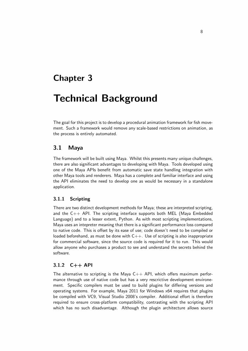
The goal for this project is to develop a procedural animation framework for fish move-ment. Such a framework would remove any scale-based restrictions on animation, asthe process is entirely automated.
3.1 Maya
The framework will be built using Maya. Whilst this presents many unique challenges,there are also significant advantages to developing with Maya. Tools developed usingone of the Maya APIs benefit from automatic save state handling integration withother Maya tools and renderers. Maya has a complete and familiar interface and usingthe API eliminates the need to develop one as would be necessary in a standaloneapplication.
3.1.1 Scripting
There are two distinct development methods for Maya; these are interpreted scripting,and the C++ API. The scripting interface supports both MEL (Maya EmbeddedLanguage) and to a lesser extent, Python. As with most scripting implementations,Maya uses an intepreter meaning that there is a significant performance loss comparedto native code. This is offset by its ease of use; code doesn’t need to be compiled orloaded beforehand, as must be done with C++. Use of scripting is also inappropriatefor commercial software, since the source code is required for it to run. This wouldallow anyone who purchases a product to see and understand the secrets behind thesoftware.
3.1.2 C++ API
The alternative to scripting is the Maya C++ API, which offers maximum perfor-mance through use of native code but has a very rescrictive development environe-ment. Specific compilers must be used to build plugins for differing versions andoperating systems. For example, Maya 2011 for Windows x64 requires that pluginsbe compiled with VC9, Visual Studio 2008’s compiler. Additional effort is thereforerequired to ensure cross-platform compatibility, contrasting with the scripting APIwhich has no such disadvantage. Although the plugin architecture allows source

CHAPTER 3. TECHNICAL BACKGROUND 9
code to be kept hidden, this combined with the compiler restrictions means thatplugins are not future proof. A new version of Maya is likely to require the sourcecode for a new compilation of the software.
3.2 Fish Biomechanics
As with existing procedural animation technologies, the biomechanics of the subjectmust be understood in order to generate realistic results. The most obvious methodwould be to model every muscle in a fish, with the effects of contraction and relaxationpropogating around the body.
(a) Salmon (b) A single salmon myotome (Source:Ramel, 2009)
Figure 3.1: Salmon muscles
Figure 3.1 shows the pattern of muscles in fish, in this case salmon. The whitelines in salmon meat (3.1a) show layers of fat separating individual myotomes (3.1b),a type of muscle. There are dozens of myotomes in a single fish, and it’s clear thatthese are not the simple, straight, elastic muscles found in other animals. The unusualshape and curvature would make modelling the propogation of force extremely diffi-cult. Even if such a model were to be produced, there would probably be significantperformance limitations due to its complexity.
Rather than engineering an accurate model of a fish, its movement must beexamined in order to produce a reverse-engineered solution. Figure 3.2a shows a fishwith at least two independent sets of muscles, allowing it produce an ’S’ shape whichincreases the surface area which can be used to push water (figure 3.2b)). Other fishcan range from having hardly any visible muscle movement (e.g. goldfish) to havingeven more pronounced curvature (eels).

CHAPTER 3. TECHNICAL BACKGROUND 10
(a) Movement cycle of a fish (Source: Mackean, 2010). (b) Force of a fish swimming(Source: Buchheim, 2006).
Figure 3.2: A fish using its tail as a paddle to generate forward momentum.

11
Chapter 4
Methods
Having ruled out an accurate biomechanical model due to the complexity of myotomemodelling, an alternative approach is to use a geometric technique. This is thetechnique used by Tu & Terzopoulos and uses a visually accurate model as a basisfor deformations. The model is deformed using a spring-mass system, with specificconnections defined as affectors, i.e. muscles.
4.1 Harmonic Oscillators
Newtonian mechanics defines a harmonic oscillator as a system which exhibits arestoring force F which is proportional to the displacement from its equilibrium x.Hookes law states:
F = −kx
Where k is a positive constant. The spring’s equilibrium position is given asx = 0. This can otherwise be expressed as:
F = md2x
dt2= −kx
The system generates a force proportionate to the amount which it is stretched.Such a system, when displaced from its equilibrium or rest position, undergoes con-tinual sinusoidal oscillations about this point; the system never repeats infinitely andnever comes to a rest (figure 4.1, ζ = 0).
4.1.1 Spring
A spring can be defined as a harmonic oscillator connecting two points. Each pointhas a mass, although in some cases a point is treated as being immovable (infinitemass). The mass of the spring itself is treated as being negligible. The constant kbecomes an effective ’stiffness’ measurement, with higher values resulting in a greaterrestorative force, increasing the frequency of oscillations.

CHAPTER 4. METHODS 12
4.1.2 Damping
Figure 4.1: Effect of damping on a harmonic oscillator (Source: Nogueira (2007))
In reality, a spring would lose its energy through air displacement and internal friction.To model this mathematically, a damping ratio is applied to the force at regularintervals, eventually reducing the energy in the system to zero, at which point it willhave found a new equilibrium (figure 4.1, ζ < 1). Other cases may require the systemto return to equilibrium without oscillating (figure 4.1, ζ >= 1).
4.1.3 Muscle
In biomechanics, skeletal muscle is analagous to an overdamped harmonic oscillator(figure 4.1, ζ > 1). Upon contraction the rest length or spring constant, k, is altered,and the muscle quickly finds its new position. In the virtual model, the spring can bedefined as a function of the two nodes which it connects. When a spring exerts forcethe two connected nodes are displaced proportionately to their mass, contrasting withtypical systems which may have an anchor such as a bone.

13
Chapter 5
Solution
5.1 Spring-Mass System
A spring-mass system can be defined by set of nodes N and springs S. Let eachnode have a mass m and position p. Let each spring have a stiffness c, and have it’srest length l defined as the vector between two nodes l = pi − pj . Such a system isinherently stable until some external force is applied, since all springs remain at theirrest lengths. The force applied to each node by the springs connected to it is:
F =∑
s ∈ springs
cs(pi − pj − ls)
A damping factor should be applied proportionately to the force exerted by springs,and also relative to the change in time between simulation updates.
5.2 Data Structure
The data structure of the nodes and springs proved to be difficult. Due to the pro-cedural nature of skeletal construction (see 5.3), it was not possible to assign all of anode’s springs at instantiation. Each node contains a vector of type NodeConnection,which contains a pointer to a spring, and the other node on that spring. This struc-ture allows maintenance of nodes to be encapsulated by their parent SkeletonSectionobjects.
5.3 Skeleton Structure
The skeleton of the virtual fish is divided into segments which have predefined con-nectivity rules and appearance. The system is designed to be fully extensible andshould allow additional segment types to be added provided that the appropriateconnectively rules are defined. Figure 5.1 illustrates the composition of each of thepredefined segments.

CHAPTER 5. SOLUTION 14
Segment Nodes Total Springs Structural Springs Multiplicity
Nose 1 0 0 1Body 4 6 2 1 . . . nTail 2 1 1 1
Figure 5.1: Skeleton components of the virtual fish.
A skeleton is constructed by adding segments to it in turn. Construction ofthe spring network is handled automatically, as defined by the rules of each specificsegment type.
Connection Total Springs Structural Springs Muscle Springs
Nose-Body 4 0 0Nose-Muscle 4 0 0Body-Body 12 8 0Body-Muscle 12 8 0Muscle-Muscle 12 8 4Body-Tail 8 4 0Muscle-Tail 8 4 0
Figure 5.2: Connectivity between components.
5.4 Maya Integration
The greatest challenge in development of the software was integration with Maya.The Maya C++ API can be used to add functionality to Maya in two ways; throughdefinition of new commands which perform a certain function within the scene onexisting nodes, or through definition of a new node type. Code must follow a veryspecific pattern in order to function properly.
5.4.1 Nodes and Attributes
Maya represents scenes through the dependency graph - a network of nodes, eachcontaining numerous attributes. This network is responsible for Maya’s ability to saveto an ASCII-based file format. The undo/redo functions are also heavily dependenton a network representation in order to work properly. Most importantly though,modifying a node anywhere in the scene hierarchy results in a representative changein all child nodes; if the extrude node were to be deleted in a PolySphere-¿Transform-¿Extrude hierarchy, the extrude operation would still function as intended.
Each node also contains a number of attributes, these are all handled internallyby Maya so that they inherit functionality such as keyframing and expressions. Whenattributes are changed, the dependency graph is used to check whether any otherattributes are affected as a result. For example when a Length attribute is changed,the Volume attribute would need to be updated; however instead of calculating thenew value, Maya marks the Volume attribute as ’dirty’. These dirty attributes are

CHAPTER 5. SOLUTION 15
then only recalculated when read, and this results in a very substantial performancegain. For this reason it is necessary to manually describe the relationships betweenattributes when using the C++ API. This is a large development overhead for a taskwhich would normally be taken care of by an optimising compiler.
Maya has a non-standard way of defining node attributes. Whilst in a typicalC++ program one might define use the following to define an array of doubles:
1 double m s p r i n g C o n s t a n t s [ 9 6 ] ;
Maya requires its own declaration for the template definition which allows it tomake new node instances. The following shows the equivalent code in the Maya API:
1 MObject m s p r i n g C o n s t a n t s ;23 MStatus Node : : i n i t i a l i z e ( )4 {5 MFnNumer icAttr ibute numAttr ;6 m s p r i n g C o n s t a n t s = numAttr . c r e a t e ( ” s p r i n g C o n s t a n t s ” , ” s p r i n g ” ,
MFNNumericAttr ibute : : kDouble , 0 . 0 ) ;7 numAttr . s e t A r r a y ( t rue ) ;8 a d d A t t r i b u t e ( m s p r i n g C o n s t a n t s ) ;9 }
This leads to highly verbose and somewhat cluttered code. Array attributes bothdefined and processed differently than standard attributes. Further still, compoundattributes are used to define data structures which contain more than one type ofvariable. This is in stark contrast with the typical approach when using an objectoriented language such as C++, which is to use objects or type definitions. In additionto requiring a custom attribute definition procedure, Maya also presents a specificAPI for reading and writing attributes. Each node has a datablock, an object whichcontains the data for all of the node’s attributes. This datablock must be navigatedusing the API in order to retreive and modify data.
Aside from the attributes necessary to perform updates to the simulation, twoglobal constants are also defined in the plugin. These are the ’speed’ and ’force’ ofthe animation. A higher speed results in a higher frequency of oscillation betweenleft and right side muscle contractions. Similarly, a higher force results in a moresignificant reduction in the muscle spring rest length, resulting in a more pronouncedswimming movement.
One of the most challenging aspects of development is full integration with Maya’sanimation controls. Maya allows the user to scrub forwards and backwards in time,and skip to any point. This contrasts with a typical OpenGL application which playscontinuously in real-time. For algorithms which aren’t reversible, this presents aproblem; the original state must be stored in order for the scene to be reproducible.Additionally, Maya does not supply the typical ∆t variable typically seen in OpenGLapplications, instead only the current time is supplied.
5.4.2 Node Implementation
In order to integrate with Maya’s timeline, a node must connect with a time node.Every new empty Maya scene contains a time node, ’time1’, however additional timenodes can be made if desired. The outTime attribute of a time node supplies data

CHAPTER 5. SOLUTION 16
in the format MTime. An attribute of this type must then be added to the customnode in order to receive this data, an inTime attribute. Node definitions are merelya static template which Maya uses in order to create new instances of a node. Sincethe definition of a node is static, it cannot perform any operations on new instancesof the node. A dependency graph connection is required between the time node’soutTime attribute and the new fish node’s inTime, however this cannot be done fromwithin the fish node definition.
5.4.3 Dependency Graph Modification
There are two methods of performing such a connection from outside the node, eitherthe connectAttr MEL command can be used, or a custom API command can be calledfrom MEL. As with all MEL, the connectAttr command is itself just an interface toan equivalent call in Maya’s C API. For non-trivial dependency graph operations,such as a series of connections being made procedurally, it is logical to hide this logicwithin a custom API command.
5.4.4 Custom API Command
The MPxCommand API class is used as a basis for new MEL commands. A com-bination of nodes and commands can be integrated into the same binary plugin, atechnique which allows attributes to be linked through reference rather than by theirname. Commands can also be called with an array of arguments for specifying optionssuch as the number of fish to be created.
For each attribute that is connected an MPlug object must be retrieved. This is areference to the instance of an attribute, and provides an interface for accessing dataand being connected in the dependency graph. The MDGModifier class is used toperform operations on a scene’s dependency graph. This is then used to procedurallyconnect each attribute, for example connecting the outTime attribute of the time1node to the inTime attributes of a dozen fish nodes. Attributes can supply data toany number of other attributes in a one-to-many relationship, but only receive theirdata from a single attribute. The connection between the attributes can be thoughtof as a pointer is in the C language; the inTime attribute literally refers to anotherattribute and the data each contains is always identical.
5.4.5 Skeletal Mesh
The topology of the skeletal mesh does not conform to any typical mesh structuresincluded in Maya. The skeleton is essentially just a collection of lines, with neithervertices nor polygons. Springs can overlap in an X-shaped arrangement, a topologywhich is incompatible with normal meshes. Hence the visualisation of the skeletonrequires custom code to be written. The MPxLocatorNode class intended as thebasis for nodes of this type; shapes that are drawn on the screen but not rendered.
Maya uses OpenGL for its viewport, and any OpenGL calls from within a Mayaplugin are invoked within this viewport. The MPxLocatorNode class templates adraw function which is automatically called by Maya when necessary. A scene redrawoccurs whenever something changes in the scene, in particular the location of the

CHAPTER 5. SOLUTION 17
camera. This function is also used as the basis for selection within the GUI, OpenGL’sselection mechanism is used to determine whether the object gets selected by aparticular mouse event.
5.5 Spring-Mass Calculation
With the stable fish structure being defined, the system finds equilibrium at its originalposition. Muscle contractions are defined by the muscle springs in the procedurallygenerated spring-mass system. Muscles form two groups, one for each side of thefish, and these are actuated as a group by the system.
The final solution for the system is:
Fi = mid2xidt2
+ ζdxidt
− si; i = 0, . . . , n
Where x is the node position, i is the set of nodes, n is the number of nodes inthe system and where:
si =∑j ∈ Ni
F si j(t)
Where s denotes the force applied to the node as a result of connected springs;the sum of the force springs connecting node i to its set of connected nodes N . Thedamping factor, ζ is applied proportionately to time.
Whilst Newton’s Second Law allows us to calculate the force applied on a massat any given point in time, it does not account for constantly changing variables;variables that are a function of time. The most sigificant effect of this is easilyillustrated with a spring analogy. As a spring returns from its maximum extent, ithas both a high velocity and high acceleration. If the ∆t of the solver is too high,the node may completely pass it’s maximum negative extent before the scene is nextupdated and drawn. As this continues, the spring is calculated as having progressivelymore energy. In a system of springs, this would rapidly cause the structure to breakdown, as the energy of the problem spring easily outweighs any possible restoringforce by the rest of the system.
In animation, the ideal ∆t is easily calculated as the time between frames. Thisresults in the lowest number of updates being performed, but in some cases it is notalways possible. The default state of the procedurally generated mesh was testedwith a ∆t of 1s/FPS = 0.04s. Whilst this results in a stable mesh, the results areneither consistent nor symmetrical. In order to alleviate this problem, the default ∆tis broken down into several smaller time-steps. The system now performs 10 updates,each with ∆t = (1s/FPS)/10 = 0.004s. The obvious disadvantage to this is thatthe system will be nearly 10 times slower, however this is also the most efficientsolution (see chapter 6). For the same reason, the solver is not capable of directlyjumping between frames. This, again, is easily resolved by performing the equivalentamount of updates with a smaller time-step.
Problems also occur when extreme values are used for the speed and force at-tributes. When the spring-mass system reaches its maximum extent, i.e. when the

CHAPTER 5. SOLUTION 18
muscles which have been contracted are closest to their preferred rest position, othersprings which should maintain their structure begin to change. This is because thesystem can no longer find resitution through movement in the muscle springs andtherefore does so in the weakest structural springs. This problem can be avoidedby not specifying extreme values for these attributes. This is not always desirable,however. In Pixar’s Finding Nemo, for example, many of the characters are animatedwith extreme movement to convey their personality.
5.6 Results
Figure 5.3 illustrates the system upon initialisation. The custom spring-mass meshis generated procedurally and remains in its equilibrium state. After a period of timehas elapsed, specified by the speed attribute, the fish will contract its muscles on theright side. Upon the next update of the system (not the same as the next frame, seesection 5.5), the fish will being to bend as if those muscles were contracted. Thechange in position is most dramatic initially; since the rest length of the muscleshave been changed but the actual length has not. Since the spring’s actual length isfarthest from it’s rest length, the associated mass (i.e. nodes) experience the mostdramatic restoring force at this point.
Figure 5.3: The procedurally generated spring-mass mesh in its equilibrium state.
Figure 5.4 shows the system in an animated state; the right side muscles have beencontracted and those springs approach their rest position. As the springs approachtheir rest position, they experience the least restorative force, indeed there is hardlyany movement in the system. The values for force and speed should be specified

CHAPTER 5. SOLUTION 19
such that this period of non-movement is as desired. Most fish will have a very shortperiod where neither side of their myotomes has been contracted.
Upon a second elapsation of the time specified by the speed attribute, the opposite(left-side) muscles will contract, and the right side muscles will regain their initialvalues for rest length. The effect of this is two fold; the muscles on the right side ofthe body will extend along the axis of the fish, and the muscles on the left side willshrink, resulting in the characteristic curvature seen in swimming fish.
Figure 5.4: The system in an animated state. Muscles on the right side have beencontracted, whilst muscles on the left are relaxed.

20
Chapter 6
Conclusion
The procedural animation works well, with the system creating animation entirelyprocedurally. The animation is quite realistic, however the fish is only able to swimsinusoidally forward. With some additional work the system would be able to generateanimation which appears to be swimming in a particular direction.
The project was very challenging, specifically because the Maya API has a steeplearning curve. Maya has a very unique structure, and the documentation can behard to follow. Maya presents a very limited model of it’s internal structure throughits API. This is a result of its dependence on backwards compatibility. With less ofthe internal structure exposed, the Maya developers have greater freedom to performinternal changes without affecting the way it behaves. Instances of the class MObjectcan refer to attributes, nodes, transforms, vertices, etc; one might expect a classcalled MAttribute or MNode to inherit from MObject, but this is not the case. Caremust be taken during development to keep track of the true type of an MObject sothat it can be attached to the correct function set.
Even with a full understanding of the API, coding for a Maya plugin is extremelyverbose and long-winded compared to other libraries or frameworks. That said, oncecompleted, Maya plugins can integrate extremely well and take advantage of the vastquantity of existing scripts, plugins and built-in functionality that Maya has to offer.Much of Maya’s functionality is developed in the same way as third party plugins.
The implementation that was developed solves the spring-mass system using New-ton’s Second Law. This results in the aforementioned boundary problems assosciatedwith extreme input, and can prevent certain resolutions of the system from beingreached. Tu & Terzopoulos solve this problem using ”a numerically stable, implicitEuler method”. Whilst this is an ideal solution, such a solution requires the useof a system of ordinary differential equations (ODEs) in order to concurrently findthe equilibrium position for all springs in the system. This is a somewhat differentapproach to the muscle actuation system in the procedural spring-mass system; theapproach of Tu & Terzopoulos finds a position of absolute restitution for the sys-tem. This means that rather than changing the rest length of the muscle springsonce per real-life muscle contraction, the rest length itself must be calculated as afunction of time. Rather than allowing the system to gradually come to a new stateof equilibrium (the speed at which this occurs is limited by the damping factor), thesystem is solved completely. A continually changing rest length produces the effect
CHAPTER 6. CONCLUSION 21
of animation even though the system is not in a state of flux. A system of ODEs isalso far slower than basing an implementation on Newton’s Second Law, even whenthat system must be solved multiple times for each time step.
Overall the project was quite successful, however it is important to integrate thefunctionality into a more complex system to make full use of it. A flocking or shoalingsystem would make best use of the procedural nature of the system, facilitating theanimation of an unlimited number of fish with minimal effort. The high computationalperformance of the developed system means that it would be perfect for such use.Another major strength of the system is the modular design of the fish construction.With little effort, the system could be adapted to produce animation for other fish-likecreatures such as sharks, whales and eels.

22
Bibliography
References
Animats. 1997. Ragdoll falling downstairs. http://www.animats.com/.
Buchheim, Jason. 2006 (June). A Quick Course in Ichthyology.http://www.marinebiology.org/fish.htm.
Cohen, Karl. 2003. Finding the Right CG Water and Fish in Nemo. http://www.awn.com/articles/technology/finding-right-cg-water-and-fish-inemoi.
Ltd., NaturalMotion. 2005. Dynamic Motion Synthesis. http://www.
naturalmotion.com/files/white_paper_dms.pdf.
Mackean, D G. 2010 (August). Fish Swimming. http://www.biology-resources.com/drawing-fish-swimming.html.
NaturalMotion Ltd. 2009. NaturalMotion euphoria. http://www.naturalmotion.
com/euphoria.htm. 24th Sept.
Nogueira, Nuno. 2007 (September). Damping.http://en.wikipedia.org/wiki/File:Damping.svg.
Pixar Animation Studios. 2003 (May). Finding Nemo.
Ramel, Gordon. 2009 (December). Fish Muscles.http://www.earthlife.net/fish/muscles.html.
Reynolds, Craig W. 1987. Flocks, herds and schools: A distributed behavioral model.Pages 25–34 of: SIGGRAPH ’87: Proceedings of the 14th annual conference onComputer graphics and interactive techniques. New York, NY, USA: ACM.
Teo, Leonard. 2003. The Making of Finding Nemo. http://features.cgsociety.org/story_custom.php?story_id=1389.
Tu, Xiaoyuan, & Terzopoulos, Demetri. 1994. Artificial fishes: physics, locomotion,perception, behavior. Pages 43–50 of: SIGGRAPH ’94: Proceedings of the 21stannual conference on Computer graphics and interactive techniques. New York,NY, USA: ACM.
Wu, Jia-chi, & Popovic, Zoran. 2003. Realistic modeling of bird flight animations.Pages 888–895 of: SIGGRAPH ’03: ACM SIGGRAPH 2003 Papers. New York,NY, USA: ACM.