matchless double- ws6502 ws6504 treadle spinning …schachtspindle.com/pdfs/m-dt-manual-post.pdf ·...
TRANSCRIPT
MATCHLESS DOUBLE-TREADLE SPINNING WHEELTM
assembly, maintenance & warranty
Find out more at schachtspindle.comSchacht Spindle Company 6101 Ben Place Boulder, CO 80301p. 303.442.3212 f. 303.447.9273
© 2019 Schacht Spindle Company, Inc. 04.19
WS6502WS6504
– 2 –
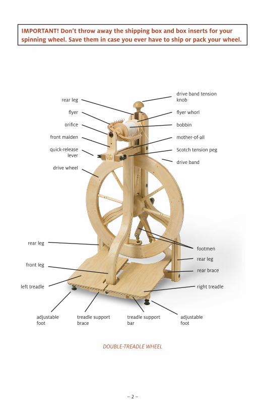
DOUBLE-TREADLE WHEEL
rear legdrive band tension knob
flyer
orifice
flyer whorl
bobbin
mother-of-all
Scotch tension peg
front maiden
quick-release lever
footmen
right treadle
adjustable foot
front legrear leg
treadle support bar
adjustable foot
treadle support brace
rear leg
left treadle
rear brace
drive band
IMPORTANT! Don’t throw away the shipping box and box inserts for your spinning wheel. Save them in case you ever have to ship or pack your wheel.
drive wheel
– 3 –
REQUIRED TOOLS#2 Phillips screwdriverbooks or blocks of wood
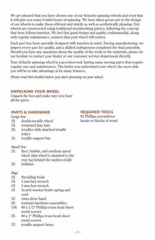
UNPACKING YOUR WHEELUnpack the box and make sure you have all the parts.
PARTS & HARDWARE Large box:1X double-treadle wheel1X tensioned lazy kate2X treadles with attached treadle
yokes1X treadle support bar
Small box:1X flyer, bobbin, and medium speed
whorl (fast whorl is attached to the rear leg behind the mother-of-all)
3X bobbins
Bag:1X threading hook1X 4 mm hex wrench1X 5 mm hex wrench1X Scotch tension brake spring and
cord1X extra drive band2X footman hardware assemblies10X #8 x 1/2" Phillips truss head sheet
metal screws2X #8 x 1" Phillips truss head sheet
metal screws1X treadle support brace
We are pleased that you have chosen one of our Schacht spinning wheels and trust that it will give you many fruitful hours of spinning. We have taken great care in the design of our wheels to make them efficient and sturdy as well as aesthetically pleasing. Our wheels are constructed using traditional woodworking joinery, following the concept that form follows function. We feel that good design and quality craftsmanship, along with regular maintenance, ensures that your wheel will endure.
Each part has been specially designed with function in mind. During manufacturing, we inspect every part for quality, and a skilled craftsperson completed the final assembly. Should you have any questions about the quality of the work or the materials, please do not hesitate to contact your dealer or our customer service department directly.
Your Schacht spinning wheel is a precision tool, having many moving parts that require regular care and maintenance. The better you understand your wheel, the more able you will be to take advantage of its many features.
Please read this booklet before you start spinning on your wheel.
– 4 –
assembling your wheelWork on a raised surface such as a table or counter (covered in a blanket or towel).
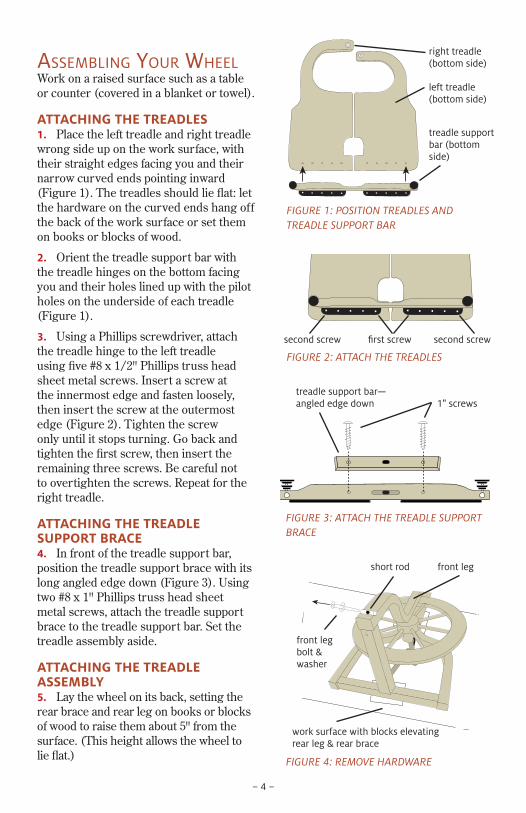
ATTACHING THE TREADLES1. Place the left treadle and right treadle wrong side up on the work surface, with their straight edges facing you and their narrow curved ends pointing inward (Figure 1). The treadles should lie flat: let the hardware on the curved ends hang off the back of the work surface or set them on books or blocks of wood.
2. Orient the treadle support bar with the treadle hinges on the bottom facing you and their holes lined up with the pilot holes on the underside of each treadle (Figure 1).
3. Using a Phillips screwdriver, attach the treadle hinge to the left treadle using five #8 x 1/2" Phillips truss head sheet metal screws. Insert a screw at the innermost edge and fasten loosely, then insert the screw at the outermost edge (Figure 2). Tighten the screw only until it stops turning. Go back and tighten the first screw, then insert the remaining three screws. Be careful not to overtighten the screws. Repeat for the right treadle.
ATTACHING THE TREADLE SUPPORT BRACE4. In front of the treadle support bar, position the treadle support brace with its long angled edge down (Figure 3). Using two #8 x 1" Phillips truss head sheet metal screws, attach the treadle support brace to the treadle support bar. Set the treadle assembly aside.
ATTACHING THE TREADLE ASSEMBLY5. Lay the wheel on its back, setting the rear brace and rear leg on books or blocks of wood to raise them about 5" from the surface. (This height allows the wheel to lie flat.)
FIGURE 3: ATTACH THE TREADLE SUPPORT BRACE
treadle support bar—angled edge down 1" screws
FIGURE 2: ATTACH THE TREADLES
first screw second screwsecond screw
FIGURE 1: POSITION TREADLES AND TREADLE SUPPORT BAR
treadle support bar (bottom side)
right treadle (bottom side)
left treadle (bottom side)
FIGURE 4: REMOVE HARDWARE
front leg bolt & washer
short rod
work surface with blocks elevating rear leg & rear brace
front leg
– 5 –
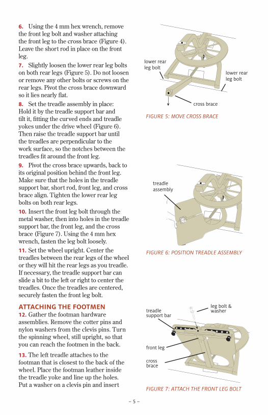
6. Using the 4 mm hex wrench, remove the front leg bolt and washer attaching the front leg to the cross brace (Figure 4). Leave the short rod in place on the front leg.7. Slightly loosen the lower rear leg bolts on both rear legs (Figure 5). Do not loosen or remove any other bolts or screws on the rear legs. Pivot the cross brace downward so it lies nearly flat. 8. Set the treadle assembly in place: Hold it by the treadle support bar and tilt it, fitting the curved ends and treadle yokes under the drive wheel (Figure 6). Then raise the treadle support bar until the treadles are perpendicular to the work surface, so the notches between the treadles fit around the front leg. 9. Pivot the cross brace upwards, back to its original position behind the front leg. Make sure that the holes in the treadle support bar, short rod, front leg, and cross brace align. Tighten the lower rear leg bolts on both rear legs. 10. Insert the front leg bolt through the metal washer, then into holes in the treadle support bar, the front leg, and the cross brace (Figure 7). Using the 4 mm hex wrench, fasten the leg bolt loosely.11. Set the wheel upright. Center the treadles between the rear legs of the wheel or they will hit the rear legs as you treadle. If necessary, the treadle support bar can slide a bit to the left or right to center the treadles. Once the treadles are centered, securely fasten the front leg bolt.
ATTACHING THE FOOTMEN12. Gather the footman hardware assemblies. Remove the cotter pins and nylon washers from the clevis pins. Turn the spinning wheel, still upright, so that you can reach the footmen in the back.
13. The left treadle attaches to the footman that is closest to the back of the wheel. Place the footman leather inside the treadle yoke and line up the holes. Put a washer on a clevis pin and insert
FIGURE 7: ATTACH THE FRONT LEG BOLT
leg bolt & washertreadle
support bar
front leg
cross brace
FIGURE 6: POSITION TREADLE ASSEMBLY
treadle assembly
FIGURE 5: MOVE CROSS BRACE
cross brace
lower rear leg bolt
lower rear leg bolt
– 6 –
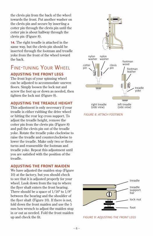
the clevis pin from the back of the wheel towards the front. Put another washer on the clevis pin and secure by inserting a cotter pin through the clevis pin until the cotter pin is about halfway through the clevis pin (Figure 8).
14. The right treadle is attached in the same way, but the clevis pin should be inserted through the footman and treadle yoke from the front of the wheel toward the back.
Fine-tuning your wheelADJUSTING THE FRONT LEGSThe front legs of your spinning wheel can be adjusted to accommodate uneven floors. Simply loosen the lock nut and screw the foot up or down as needed, then tighten the lock nut (Figure 9).
ADJUSTING THE TREADLE HEIGHTThis adjustment is only necessary if your treadle is either rubbing the drive wheel or hitting the rear leg cross support. To adjust the treadle height, remove the cotter pin from the clevis pin (Figure 8) and pull the clevis pin out of the treadle yoke. Rotate the treadle yoke clockwise to raise the treadle and counterclockwise to lower the treadle. Make only two or three turns and reassemble the footman and treadle yoke. Repeat this adjustment until you are satisfied with the position of the treadle.
ADJUSTING THE FRONT MAIDENWe have adjusted the maiden stop (Figure 10) at the factory, but you should check to see that it is adjusted properly for your wheel. Look down from the top to where the flyer shaft enters the front bearing. There should be a space of 1/16" to 1/8" between the bearing and the shoulder of the flyer shaft (Figure 10). If there is not, fold down the front maiden and use the 5 mm hex wrench to adjust the maiden stop in or out as needed. Fold the front maiden up and check the fit. FIGURE 9: ADJUSTING THE FRONT LEGS
lock nut
foot
treadle support bar
treadle
FIGURE 8: ATTACH FOOTMEN
left treadle (side view)
right treadle (side view)
clevis pin
footman wood
footman leather
nylon washer
nylon washer
treadle yoke
cotter pin
– 7 –
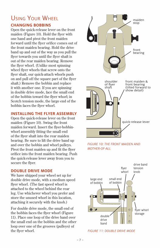
using your wheelCHANGING BOBBINSOpen the quick-release lever on the front maiden (Figure 10). Hold the flyer with one hand and pivot the front maiden forward until the flyer orifice comes out of the front maiden bearing. Hold the drive band up and out of the way as you pull the flyer towards you until the flyer shaft is out of the rear maiden bearing. Remove the flyer whorl. (Unlike most spinning wheel flyer whorls that screw onto the flyer shaft, our quick-attach whorls push on and pull off the square part of the flyer shaft.) Remove the bobbin and replace it with another one. If you are spinning in double drive mode, face the small end of the bobbin toward the flyer whorl; in Scotch tension mode, the large end of the bobbin faces the flyer whorl.
INSTALLING THE FLYER ASSEMBLYOpen the quick-release lever on the front maiden (Figure 10). Swing the front maiden forward. Insert the flyer-bobbin-whorl assembly fitting the small end of the flyer shaft into the rear maiden bearing. Be sure to lift the drive band up and over the bobbin and whorl pulleys. Pivot the front maiden up and fit the flyer orifice into the front maiden bearing. Push the quick-release lever away from you to secure the flyer.
DOUBLE DRIVE MODEWe have shipped your wheel set up for double drive mode, with a medium speed flyer whorl. (The fast speed whorl is attached to the wheel behind the rear leg. Use whichever whorl you prefer and store the unused whorl in this location, attaching it securely with the knob.)
For double drive mode, the small end of the bobbin faces the flyer whorl (Figure 11). Place one loop of the drive band over the small end on the bobbin and the other loop over one of the grooves (pulleys) of the flyer whorl. FIGURE 11: DOUBLE DRIVE MODE
large end of bobbin
small end of bobbin
flyer whorl
flyer whorl storage
drive band tension knob
double drive band
FIGURE 10: THE FRONT MAIDEN AND MOTHER-OF-ALL
shoulder of flyer shaft
front maiden & front bearing (tilted forward to show detail)
quick-release lever
maiden stop
front bearing
– 8 –
Adjust the tension on the drive band by turning the drive band tension knob. Start with a loose drive band. Begin to treadle slowly, tightening the tension knob until the flyer and bobbin both begin to turn. Now you can begin to spin. Turn the tension knob in a clockwise direction to increase the take-up of the yarn onto the bobbin or counter-clockwise to reduce the amount of take-up.
SCOTCH TENSION OR FLYER LEAD MODERemove the flyer (see the “Changing Bobbins” section) and install the Scotch tension brake spring and cord.
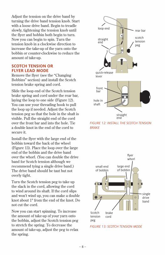
Slide the loop end of the Scotch tension brake spring and cord under the rear bar, laying the loop to one side (Figure 12). You can use your threading hook to pull the loop up if needed. Adjust the Scotch tension peg so that the hole in the shaft is visible. Pull the straight end of the cord over the front bar and into the hole. Tie a double knot in the end of the cord to secure it.
Install the flyer with the large end of the bobbin toward the back of the wheel (Figure 13). Place the loop over the large end of the bobbin and the drive band over the whorl. (You can double the drive band for Scotch tension although we recommend tying a single drive band.) The drive band should be taut but not overly tight.
Turn the Scotch tension peg to take up the slack in the cord, allowing the cord to wind around its shaft. If the cord slips and won’t wind up, you can make a double knot about 1" from the end of the knot. Do not cut the cord.
Now you can start spinning. To increase the amount of take-up of your yarn onto the bobbin, adjust the Scotch tension peg to stretch the spring. To decrease the amount of take-up, adjust the peg to relax the spring.
FIGURE 13: SCOTCH TENSION MODE
rear bar
scotch tension peg
quick-release lever
straight end
loop end
FIGURE 12: INSTALL THE SCOTCH TENSION BRAKE
single drive band
Scotch tension peg
brake cord
small end of bobbin
large end of bobbin
flyer whorl
front bar
hole in shaft
straight end
– 9 –
best to tie a separate drive cord following the instructions above. Several drive cords can be left on the wheel at the same time: simply fold up the ones not in use and let them hang from the maiden or the front leg.
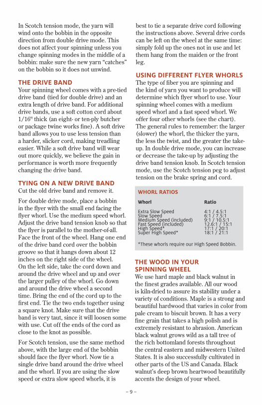
USING DIFFERENT FLYER WHORLSThe type of fiber you are spinning and the kind of yarn you want to produce will determine which flyer whorl to use. Your spinning wheel comes with a medium speed whorl and a fast speed whorl. We offer four other whorls (see the chart). The general rules to remember: the larger (slower) the whorl, the thicker the yarn, the less the twist, and the greater the take-up. In double drive mode, you can increase or decrease the take-up by adjusting the drive band tension knob. In Scotch tension mode, use the Scotch tension peg to adjust tension on the brake spring and cord.
In Scotch tension mode, the yarn will wind onto the bobbin in the opposite direction from double drive mode. This does not affect your spinning unless you change spinning modes in the middle of a bobbin: make sure the new yarn “catches” on the bobbin so it does not unwind.
THE DRIVE BAND Your spinning wheel comes with a pre-tied drive band (tied for double drive) and an extra length of drive band. For additional drive bands, use a soft cotton cord about 1/16" thick (an eight- or ten-ply butcher or package twine works fine). A soft drive band allows you to use less tension than a harder, slicker cord, making treadling easier. While a soft drive band will wear out more quickly, we believe the gain in performance is worth more frequently changing the drive band.
TYING ON A NEW DRIVE BANDCut the old drive band and remove it.
For double drive mode, place a bobbin in the flyer with the small end facing the flyer whorl. Use the medium speed whorl. Adjust the drive band tension knob so that the flyer is parallel to the mother-of-all. Face the front of the wheel. Hang one end of the drive band cord over the bobbin groove so that it hangs down about 12 inches on the right side of the wheel. On the left side, take the cord down and around the drive wheel and up and over the larger pulley of the whorl. Go down and around the drive wheel a second time. Bring the end of the cord up to the first end. Tie the two ends together using a square knot. Make sure that the drive band is very taut, since it will loosen some with use. Cut off the ends of the cord as close to the knot as possible.
For Scotch tension, use the same method above, with the large end of the bobbin should face the flyer whorl. Now tie a single drive band around the drive wheel and the whorl. If you are using the slow speed or extra slow speed whorls, it is
THE WOOD IN YOUR SPINNING WHEELWe use hard maple and black walnut in the finest grades available. All our wood is kiln-dried to assure its stability under a variety of conditions. Maple is a strong and beautiful hardwood that varies in color from pale cream to biscuit brown. It has a very fine grain that takes a high polish and is extremely resistant to abrasion. American black walnut grows wild as a tall tree of the rich bottomland forests throughout the central eastern and midwestern United States. It is also successfully cultivated in other parts of the US and Canada. Black walnut’s deep brown heartwood beautifully accents the design of your wheel.
WHORL RATIOS
Whorl Ratio
Extra Slow Speed 4:1 / 4.5:1Slow Speed 6:1 / 7.5:1Medium Speed (included) 9:1 / 10.5:1Fast Speed (included) 12.6:1 / 15:1High Speed* 17:1 / 20:1Super High Speed* 18:1 / 21:1
*These whorls require our High Speed Bobbin.
– 10 –
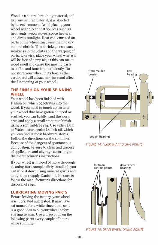
front maiden bearing
rear bearing
bobbin bearings
FIGURE 14: FLYER SHAFT OILING POINTS
Wood is a natural breathing material, and like any natural material, it is affected by its environment. Avoid placing your wheel near direct heat sources such as heat vents, wood stoves, space heaters, and direct sunlight. Heat concentrated on parts of the wheel can cause them to dry out and shrink. This shrinkage can cause weakness in the joints and the warping of parts. Likewise, place your wheel where it will be free of damp air, as this can make wood swell and cause the moving parts to stiffen and function inefficiently. Do not store your wheel in its box, as the cardboard will attract moisture and affect the functioning of your wheel.
THE FINISH ON YOUR SPINNING WHEELYour wheel has been finished with Danish oil, which penetrates into the wood. If you need to touch up parts of your wheel that have gotten chipped or scuffed, you can lightly sand the worn area and apply a small amount of finish using a soft, lint-free rag. Use either Deft or Watco natural color Danish oil, which you can find at most hardware stores. Follow the directions on the container. Because of the dangers of spontaneous combustion, be sure to clean and dispose of applicators and oily rags according to the manufacturer’s instructions.
If your wheel is in need of more thorough cleaning (for example, dirty treadles), you can wipe it down using mineral spirits and a rag, then reapply Danish oil. Be sure to follow the manufacturer’s directions for disposal of rags.
LUBRICATING MOVING PARTSBefore leaving the factory, your wheel was lubricated and tested. It may have sat unused for a while since then, so it is a good idea to oil your wheel before starting to spin. Use a drop of oil on the following parts every couple of hours while spinning:
FIGURE 15: DRIVE WHEEL OILING POINTS
drive wheel bearings
footman contact points
– 11 –
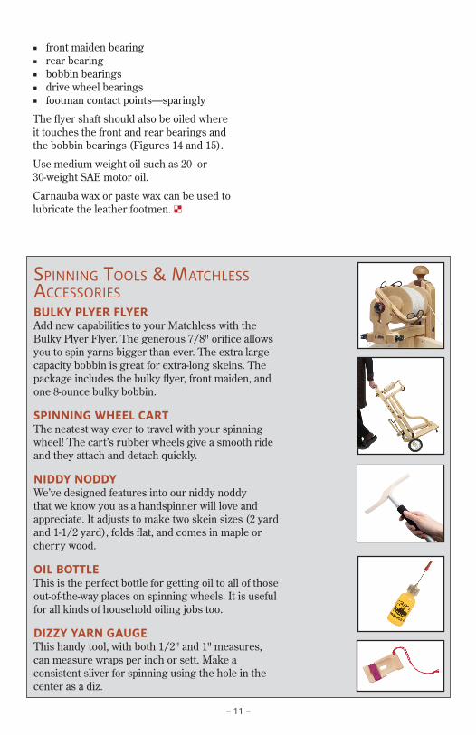
spinning tools & matchless accessoriesBULKY PLYER FLYER Add new capabilities to your Matchless with the Bulky Plyer Flyer. The generous 7/8" orifice allows you to spin yarns bigger than ever. The extra-large capac ity bobbin is great for extra-long skeins. The package includes the bulky flyer, front maiden, and one 8-ounce bulky bobbin.
SPINNING WHEEL CARTThe neatest way ever to travel with your spinning wheel! The cart’s rubber wheels give a smooth ride and they attach and detach quickly.
NIDDY NODDYWe’ve designed features into our niddy noddy that we know you as a handspinner will love and appreciate. It adjusts to make two skein sizes (2 yard and 1-1/2 yard), folds flat, and comes in maple or cherry wood.
OIL BOTTLEThis is the perfect bottle for getting oil to all of those out-of-the-way places on spinning wheels. It is useful for all kinds of household oiling jobs too.
DIZZY YARN GAUGEThis handy tool, with both 1/2" and 1" measures, can measure wraps per inch or sett. Make a consistent sliver for spinning using the hole in the center as a diz.
■ front maiden bearing ■ rear bearing ■ bobbin bearings ■ drive wheel bearings ■ footman contact points—sparingly
The flyer shaft should also be oiled where it touches the front and rear bearings and the bobbin bearings (Figures 14 and 15).
Use medium-weight oil such as 20- or 30-weight SAE motor oil.
Carnauba wax or paste wax can be used to lubricate the leather footmen. •

– 12 –
MAINTENANCE NOTESYour wheel is both a carefully engineered piece of equipment and a fine piece of furniture. A regular schedule of care and maintenance will ensure you and your Schacht spinning wheel many productive years together.
■ Periodically clean excess fibers from all parts of your wheel. ■ Periodically lubricate the moving parts. ■ Touch up worn or chipped areas with
fine sandpaper and Danish oil. ■ Check screws for tightness. (Changes
in the environment and the action of spinning can cause screws and nuts to loosen over time.)
WHEEL SERIAL NUMBERThe serial number of your spinning wheel is stamped into the wood on the rear of the mother-of-all. The first six digits of the serial number are the date of assembly. The remaining digits are a sequence number for wheels built that day.
TWO YEAR LIMITED WARRANTYSchacht products are warranted, to the original consumer purchaser, by Schacht Spindle Company to be free of defects in material and workmanship. Schacht Spindle Company’s obligation under this Warranty shall be limited to the repair or replacement of any part or parts which may prove defective within two (2) years following the date of original purchase by the consumer, and which Schacht Spindle Company’s examination shall disclose to our satisfaction to be thus defective.
If a problem with this Schacht Spindle Company product develops during the warranty period, first contact the Schacht Spindle Company dealer from whom you made the purchase. If the problem cannot be handled through your dealer, contact our customer service department. At our option, it may be required that the product be returned to our factory, freight prepaid, for inspection and repair and/or replacement.
This Warranty covers normal consumer use and does not cover damage which occurs in shipment or damage that results from alteration, accident, misuse, abuse, or neglect.
This Warranty gives you specific legal rights, and you may also have other rights that may vary from state to state.
This Warranty is not valid for equipment that has served as dealer floor models that have outlived the term of the warranty or products that have been purchased through a third party.
Proof of purchase date and a serial number when applicable are required for all Warranty claims.