material and equipment standard for low voltage …
TRANSCRIPT

IPS-M-EL-165
This Standard is the property of Iranian Ministry of Petroleum. All rights are reserved to the owner. Neither whole nor any part of this document may be disclosed to any third party, reproduced, stored in any retrieval system or transmitted in any form or by any means without the prior written consent of the Iranian Ministry of Petroleum.
MATERIAL AND EQUIPMENT STANDARD
FOR
LOW VOLTAGE INDUSTRIAL
AND
FLAMEPROOF a.c. MOTOR CONTROL CENTERS (MCC)
ORIGINAL EDITON
MAY 1993

May 1993
IPS-M-EL-165
1
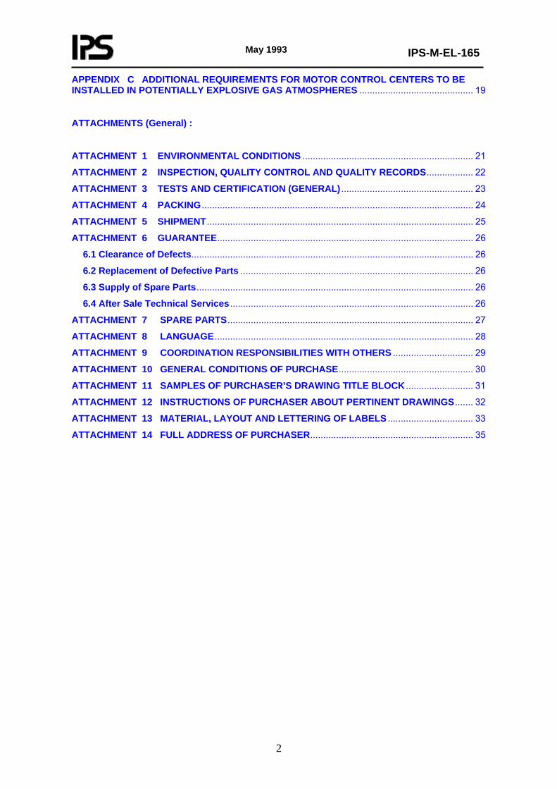
CONTENTS : PAGE No.
0. INTRODUCTION ...........................................................................................................................3
1. SCOPE ............................................................................................................................................ 4
2. REFERENCES ................................................................................................................................ 4
3. DEFINITIONS.................................................................................................................................. 6
4. UNITS ………………………………………………………………………………………………………6
5. SERVICE CONDITIONS ………………………………………………………………………………….6
6. BASIC DESIGN, CONSTRUCTION AND RATING …………………………………………………...7
6.1 General Arrangement ............................................................................................................. 6
6.2 Busbar ...................................................................................................................................... 8
6.3 Circuit Breakers ...................................................................................................................... 8
6.4 Motor Starters.......................................................................................................................... 9
6.5 Air-break Switches, Air-break Disconnectors and Fuse Combination Units.................... 9
6.6 Extensions ............................................................................................................................... 9
6.7 Spar Panel................................................................................................................................ 9
6.8 Provisions for Remote Control.............................................................................................. 9
6.9 Coordination of Short Circuit Protective Devices ............................................................... 9
6.10 Information to be Given on the LV Motor Control Centers............................................. 10
6.11 Nameplates and Labels ...................................................................................................... 10
6.12 Provision for Handling, Erection, Special Tools and Devices........................................ 11
7. INSPECTION, QUALITY CONTROL AND QUALITY RECORDS ............................................... 11
8. TESTS AND CERTIFICATES ....................................................................................................... 11
8.1 General Requirements for Tests ......................................................................................... 11
8.2 Specific Requirements for Tests ......................................................................................... 11
9. FINISHB ........................................................................................................................................ 12
10. INFORMATION FOR MANUFACTURER/SUPPLIER................................................................ 12
11. DOCUMENTATION TO BE SUPPLIED BY MANUFACTURER/SUPPLIER ............................ 12
12. PACKING .................................................................................................................................... 12
13. SHIPMENT .................................................................................................................................. 12
14. GUARANTEE.............................................................................................................................. 12
15. SPARE PARTS ........................................................................................................................... 12
16. LANGUAGE ................................................................................................................................ 12
17. COORDINATION, RESPONSIBILITY WITH OTHERS.............................................................. 13
APPENDICES :
APPENDIX A EXAMPLE OF TYPICAL DATA SHEET FOR MOTOR CONTROL CENTER .... 14
APPENDIX B LIST OF DRAWINGS , DOCUMENTS , MANUALS AND CERTIFICATES TO BE SUBMITTED BY MANUFACTURER /SUPPLIER ........................................................................... 18
May 1993
IPS-M-EL-165
2
APPENDIX C ADDITIONAL REQUIREMENTS FOR MOTOR CONTROL CENTERS TO BE INSTALLED IN POTENTIALLY EXPLOSIVE GAS ATMOSPHERES ............................................ 19
ATTACHMENTS (General) :
ATTACHMENT 1 ENVIRONMENTAL CONDITIONS .................................................................. 21
ATTACHMENT 2 INSPECTION, QUALITY CONTROL AND QUALITY RECORDS.................. 22
ATTACHMENT 3 TESTS AND CERTIFICATION (GENERAL) ................................................... 23
ATTACHMENT 4 PACKING ......................................................................................................... 24
ATTACHMENT 5 SHIPMENT....................................................................................................... 25
ATTACHMENT 6 GUARANTEE................................................................................................... 26
6.1 Clearance of Defects............................................................................................................. 26
6.2 Replacement of Defective Parts .......................................................................................... 26
6.3 Supply of Spare Parts........................................................................................................... 26
6.4 After Sale Technical Services .............................................................................................. 26
ATTACHMENT 7 SPARE PARTS............................................................................................... 27
ATTACHMENT 8 LANGUAGE.................................................................................................... 28
ATTACHMENT 9 COORDINATION RESPONSIBILITIES WITH OTHERS ............................... 29
ATTACHMENT 10 GENERAL CONDITIONS OF PURCHASE.................................................... 30
ATTACHMENT 11 SAMPLES OF PURCHASER’S DRAWING TITLE BLOCK .......................... 31
ATTACHMENT 12 INSTRUCTIONS OF PURCHASER ABOUT PERTINENT DRAWINGS....... 32
ATTACHMENT 13 MATERIAL, LAYOUT AND LETTERING OF LABELS ................................. 33
ATTACHMENT 14 FULL ADDRESS OF PURCHASER............................................................... 35

May 1993
IPS-M-EL-165
3
0. INTRODUCTION
This Standard may not cover every requirement or diversity of conditions at each locality, but this is recognized and the write up is sufficiently flexible to allow individual companies in oil, gas and petrochemical industries of Iran to exercise their own judgment in these situations, with due consideration to the existing electrical installations of oil gas and petrochemical industries in Iran and the pertinent prevailing hazards.

May 1993
IPS-M-EL-165
4
1. SCOPE
1.1 This Standard Specification covers the minimum technical requirements for design, manufacture, quality control, testing, finishing and shipment of low voltage a.c. industrial and flameproof motor control centers, indoor or outdoor which shall be installed in oil, gas, and petrochemical industries in Iran under the service conditions stated in Clause 5 of this Standard Specifications.
Only the general requirements of industrial and explosion-proof motor control centers are given in this Standard Specification, requirements for individual motor control centers will be given in pertinent data sheet, single line diagram and/or in requisition.
2. REFERENCES
Throughout this Standard the following dated and undated standards/codes are referred to. These referenced documents shall, to the extent specified herein, form a part of this standard. For dated references, the edition cited applies. The applicability of changes in dated references that occur after the cited date shall be mutually agreed upon by the Company and the Vendor. For undated references, the latest edition of the referenced documents (including any supplements and amendments) applies.
IEC (INTERNATIONAL ELECTROTECHNICAL COMMISSION)
IEC 27 "Letters Symbols to be used in Electrical Technology"
IEC 34.12 "Starting Performance of Single Speed 3 Phase Cage Induction Motors for Voltages upto 660 V"
IEC 50 "International Electrotechnical Vocabulary"
IEC 51 "Recommendations for Indicating Electrical Measuring Instruments and their Accessories"
IEC 59 "Standard Current Ratings"
IEC 73 "Color of Indicating Light and Push Buttons"
IEC 79 "Electrical Apparatus for Explosive Gas Atmospheres"
IEC 112 "Method for Determining the Comparative and the Proof Tracking Indices of Solid Insulat- ing Material under Moist Condition (for Creepage and Clearance Distances)"
IEC 144 "Degrees of Protection of Enclosures for LV Switchgear and Controlgear"
IEC 157 "LV Switchgear and Controlgear"
IEC 158 "LV Controlgear Part 1 Contactors"
IEC 185 "Current Transformers"
IEC 186 "Voltage Transformers"
IEC 255 "Electrical Relays"
IEC 269 "LV Fuses with High Breaking Capacity"
IEC 292.1 "Low Voltage Motor Starters Part 1. Direct on-line (Full voltage) a.c. Starters"
IEC 292.2 "Low Voltage Motor Starters Part 2 "Reduced Voltage a.c. Starters Star-delta Starters"
IEC 292.4 "Low Voltage Motor Starters Part 4 Two Step Auto-transformer Starters"
IEC 337 "Control Switches (LV Switching) Devices for Control and Auxiliary Circuits Including Contactor Relays"

May 1993
IPS-M-EL-165
5
IEC 364 "Electrical Installation of Building"
IEC 391 "Marking of Insulated Conductors"
IEC 408 "Low Voltage Air Break Switches, Air Break Disconnectors and Fuse Combination Units"
IEC 414 "Safety Requirements for Indicating and Recording Electrical Measuring Instrument and their Accessories.
IEC 439 "Factory Built Assemblies of LV Switchgear and Controlgear" See also EN (European Norm) 60-439.1.
IEC 445 "Identification of Apparatus Terminals and General Rules for a Uniform System of Ter- minal Marking Using an Alphanumeric Notation"
IEC 446 "Identification of Insulated and Bare Conductors by Color"
IEC 447 "Standard Directions of Movements of Actuators which Controls the Operation of Electri- cal Apparatus"
IEC 529 "Classification of Degrees of Protection Provided by Enclosures"
IEC 617 "Graphical Symbols for Diagrams"
IPS (IRANIAN PETROLEUM STANDARD)
IPS-M-EL-140 "Material and Equipment Standard for Industrial a.c. Switchgear and Controlgear Assem- bly"
IPS-M-EL-142 "Material and Equipment for Industrial and Flameproof a.c. Motor Starters"
IPS-M-EL-185 "Material and Equipment Standard for Industrial and Explosion-proof Motor Remote Control Stations"
Notes:
1) Where standard other than "IEC" are used manufacturer/supplier shall submit the applied equivalent standards and the pertinent deviations from IEC standards specified.
2) The testing and certification by the following authorities are acceptable where relevant.
- Association of Short circuit Testing Authorities (ASTA).
- European Organization for Testing and Certification (EOTC) under CENELEC Administration.
- Electrical Equipment Certification Services (EECS).
3. DEFINITIONS
In order to have precise and clear definitions for Low Voltage (LV), Medium Voltage (MV) and High Voltage (HV) standards, the ISIRI No. 6 (1987) derived from the IEC standard No. 38 (1983) with some changes is quoted below:
a) Low Voltage
Low Voltage (LV) is defined as voltages below 1000 volts in a 3 phase 4 wire 50 Hz system.
b) Medium Voltage
Medium Voltage (MV) is defined as voltages higher than 1000 volts up to and including 66 Kv in a 3 phase, 3 wire, 50 Hz system.
c) High Voltage
High Voltage (HV) is defined as voltages higher than 66 Kv in a 3 phase, 3 wire, 50 Hz

May 1993
IPS-M-EL-165
6
system.
High voltage are mainly used for power transmission and unlikely to have application for the purpose of this Standard Specification.
This Standard Specification is for "LV" motor control centers.
4. UNITS
International System of units (SI) in accordance with IPS-E-GN-100 shall be used.
5. SERVICE CONDITIONS
5.1 Environmental Conditions
See Attachment 1.
5.2 Electricity Supply
5.2.1 Power supply in site is 400/230 volt 3 phase, 4 wire 50 Hz, solidly neutral earthed system, unless otherwise specified in data sheet.
5.2.2 Fault level is: (*) MVA (for industrial MCC).
" " " : (*) MVA (for flameproof MCC).
(*) See data sheet.
5.2.3 Voltage variations ± 10% (IEC 38).
5.2.4 Frequency variation ± 5% (IEC 242).
5.3 Area Classification of Location of Installation
5.3.1 The L.V. motor control centers shall be installed in safe areas as far as possible, for which industrial type of equipment shall be designed, however when motor control centers have to be installed in hazardous locations, the requirements of standards of electrical apparatus for potentially explosive atmospheres described in Appendix C shall be fulfilled.
6. BASIC DESIGN, CONSTRUCTION AND RATING
6.1 General Arrangement
6.1.1 MCC shall be of the sheet metal cubicle, free standing, vertical, floor mounting.
Depending on the location of the MCC one of the following minimum degree of protection of the enclosure against contact with live or moving parts and against ingress of solid foreign bodies and liquids as per IEC Publication 529 shall be selected:
- Indoors in enclosed building IP 41
- Outdoors protected by canopy IP 54
- Outdoors unprotected (example remote control units) IP 65

May 1993
IPS-M-EL-165
7
Notes:
1) The above mentioned degrees of ingress protecting shall be applied only when no mention is made of degree of IP in data sheets.
2) When outdoor equipment are requested, the vendor shall submit full detailed drawing of canopy to be provided by purchaser.
6.1.2 Motor control center shall be so designed to minimize any risk of short circuit and to ensure personal and operational safety during all operating conditions, inspection, maintenance, the connection of main, control and auxiliary cables and the equipping and commissioning of spare panels while the MCC is live and in operation.
6.1.3 Each MCC assembly shall comprise, incoming/outgoing with or without bus sectionalizer circuit together with a single busbar system as shown in single line diagram, and detailed in data sheets in Appendix A.
6.1.4 In certain circumstances the use of contactors, air break switches, disconnections and fuse combination units for control of certain minor circuit may be needed as shown in single line diagram and circuit data sheets.
6.1.5 Each MCC assembly shall contain necessary auxiliary control devices, specified instruments and protection current transformers, voltage transformers, control meters and meter switches where applicable.
6.1.6 A multitier arrangement of motor starters for industrial purpose is acceptable but no relay reset button, selector switch or operating device shall be more than 1750 mm and less than 150 mm above the floor level.
6.1.7 Sheet steel barriers shall be provided between the starters, compartments in each vertical section, and control and power compartments.
6.1.8 Each circuit shall be housed in a separate cubicle compartment with the motor starters mounted on a draw out type chassis, Interlocks shall be provided to ensure that the chassis cannot be withdrawn when the motor starter is on and the equipment is safe to operate or examine in all conditions of services.
6.1.9 The total enclosure and individual panel cubicles and compartments shall be so designed and constructed to prevent the passage of flame, and fumes from one section to another.
6.1.10 Circuit breakers, contactors instruments, busbar; connections and current transformers shall all be housed in compartments.
6.1.11 The MCC shall be designed to withstand the effects of the internal and external faults.
6.1.12 Cubicles structure shall be rigid to prevent misalignment.
6.1.13 Isolation contacts temporarily exposed when air circuit breakers or starters are withdrawn shall automatically be shielded behind lockable covers.
6.1.14 Access to cubicles, other than with drawable circuit breaker and starter front panels, shall be by lockable mild steel doors, and at the back via door, and or removable mild steel sheets.
6.1.15 Provision shall be made for all main and auxiliary cable entries.
6.1.16 Provision shall be made for the future extension of the MCC in either ends.
6.1.17 An earth busbar shall be provided for the entire length of MCC. It shall be provided with at least two solderless crimp type terminals located at the ends of the earth bars.
The size of earthing busbar shall be compatible with the fault level. But should not be less than 70 SQ. mm. 6.1.18 Means shall be provided for lifting the MCC into installed position.
May 1993
IPS-M-EL-165
8
6.1.19 Interchangeability
6.1.19.1 Electrically identical components shall be of one type and make.
6.1.19.2 With drawable sub-assemblies with identical electrical functions and capacities shall be mechanically interchangeable, but with different electrical functions or capacities shall not be interchangeable.
6.2 Busbar
6.2.1 Busbar and main connections shall be of hard drawn high conductivity electrolytic copper sheathed or wrapped with color coded self extinguishing resin, PVC tape or shrunk on sleeving.
6.2.2 Normal and short time current rating shall be in accordance with Clauses 4.2 and 4.3 of IEC publication 439.1.
6.2.3 The neutral bar shall have half the cross section of the phase bars under normal conditions and shall be provided with neutral link. The neutral bus shall be perfectly insulated from metallic surrounding.
6.2.4 All busbars and joints shall be tin plated (unless otherwise specified in requisition) and shall be tightened to manufacturer’s standard.
6.2.5 Space shall be provided for incoming cables in vicinity of busbars.
6.2.6 The load terminals on starters located at the bottom of a vertical section shall be arranged to permit easy connections of outgoing cables.
6.2.7 Busbars shall be the same size throughout the length of the motor starter assembly, and shall be fully current rated over the whole length of the MCC and shall not be rated less than incoming and bus section circuit breakers rating.
6.2.8 Vertical busbars shall also be wrapped with PVC sheathing or shrunk on sleeving. The insulation shall be color coded.
6.2.9 The MCC shall be so designed and constructed as to prevent arcs occurring in one main busbar from flashing through or around bus tie units to the other parts of main busbars.
6.2.10 Protective covers shall be provided for all live parts of the bus when the breaker is removed.
6.2.11 Bus connections to the circuit breakers shall match the breaker rating.
6.2.12 The busbars shall be mechanically braced to withstand short circuit current.
6.2.13 busbars and busbar connections shall be supported and proportioned as to be capable of safely withstanding stresses to which they may be subjected, including those due to short circuit and climatic conditions.
6.2.14 Bus trunking (ducting)
6.2.14.1 Where bus trunking is required for incoming connections. The MCC shall be provided with the manufacturer’s standard flanged entry terminal box suitable for connection in the vertical direction, with the bus trunking approaching from the above unless otherwise agreed.
6.3 Circuit Breakers
For details of circuit breakers covering incoming, outgoing or bus section reference to be made to Standard IPS-M-EL-140.

May 1993
IPS-M-EL-165
9
6.4 Motor Starters
For details of motor starters covering direct on line, star-delta and auto transformer motor starters see Standard IPS-M-EL-142.
6.5 Air-break Switches, Air-break Disconnectors and Fuse Combination Units
6.5.1 When airbreak switches, airbreak disconnectors, airbreak switch disconnectors and fuse combination units are requested in data sheets, they shall comply with the requirements of IEC publication No. 408.
6.5.2 Where fuses and switches of fuse combination units are mounted in separate enclosures, they shall be interlocked such that fuse compartment doors cannot be opened unless the switch is open, and the switch cannot be closed unless the fuse compartment door is closed.
6.5.3 Fuses shall be of the high breaking capacity type to IEC publication No. 269.
6.5.4 Fuse sizes protecting circuits which supply motors shall be kept to a minimum compatible with the starting time and current of pertinent motors.
6.5.5 Fuse carriers shall be such that when they are withdrawn, the operator is protected from accidental contact with any live metal of the fuse link, and fuse contacts.
6.5.6 Isolators shall be capable of carrying the peak asymmetrical let through current of the fuses and shall be capable of carrying the let through current of the fuses for the total break time for any current throughout the current/total break time characteristic of the fuse that is fitted into the fuse base, holder or carrier.
6.6 Extensions
The MCC including the framework, busbars, bus wiring, earth bar, etc., shall be suitable in all respects for extension at both ends, so that only the minimum of work will be required to make such extension.
6.7 Spar Panel
10% spare capacity at different rating to be considered as shown in single line diagram.
6.8 Provisions for Remote Control
6.8.1 Terminals with marking shall be provided on motor starters to satisfy the requirements of method of control specified in data sheet.
6.8.2 Where automatic or programmable logic control (PLC) system are specified in data sheet, details of schematic and sequence of operation will be coordinated by purchaser.
6.9 Coordination of Short Circuit Protective Devices
6.9.1 The setting or selection of the short circuit protective devices with the MCC should where possible be so graded that a short circuit occurring in any outgoing branch circuit, is cleared by the switching device installed in the faulted branch circuit without affecting the other outgoing branch circuits, thus ensuring selectivity of the protective system.

May 1993
IPS-M-EL-165
10
6.10 Information to be Given on the LV Motor Control Centers
6.10.1 Information on the outside
6.10.1.1 Each MCC shall be provided with one or more general nameplates located in a place such that they are visible and legible when the assembly is installed.
The information given on these general nameplates shall be as follows but not be limited to:
a) Purchaser’s name and order No.
b) The year of manufacture.
c) The manufacturer name or trade mark.
d) Type designation and serial number, making it possible to obtain relevant information from the manufacturer.
e) Rated operational voltage and frequency.
f) Short circuit strength and time.
g) Degree of protection.
h) Dimensions: height, width (length) and depth.
i) Weight.
6.10.1.2 Identifying circuit label(s):
a) Further to the general nameplates, each circuit of the MCC shall be provided with identifying circuit labels, fitted on the fixed portion.
6.11 Nameplates and Labels
6.11.1 General Requirements
The nameplates, labels and their fixing materials shall be proven, durable under the service conditions specified for the MCC.
They shall be corrosion and moisture resistant, and provided with indelible inscription in the language specified in Attachment 8.
Stainless nameplates, and traffolite or equivalent are acceptable.
Note:
For material layout and lettering of labels see Attachment 13.
6.11.2 Fixing
Nameplates and labels shall be fixed to the MCC and its components (functional units) by means of proven durable non corrosive self threading screws.
Holes for fixing shall not influence in any way the degree of ingress protection of enclosure.
6.11.3 Color
6.11.3.1 Circuit designation or nomenclature to be engraved into the white layer of traffolite to give black lettering on a white background.

May 1993
IPS-M-EL-165
11
6.11.3.2 Instruction plates where specified shall be yellow with black inscription.
6.11.3.3 Warning or caution plates where necessary shall be red with white inscription.
6.12 Provision for Handling, Erection, Special Tools and Devices
6.12.1 In case of multicubicle and multisection assembly, lifting eye bolts or angles shall be furnished for crane hook up of slings during installation.
6.12.2 Specific instruction for handling of MCC before installation shall indicate the measures that are of particular importance for the proper movement of assembly on the ground.
6.12.3 The following accessories and device shall be furnished on each assembly or group of assemblies in the same MCC room:
6.12.3.1 Handle for moving the breaker into the connected, test, or disconnected position (where applicable).
6.12.3.2 Breaker maintenance closing device.
6.12.3.3 Device for manually charging the stored energy operating mechanism on electrically operated breakers.
6.12.3.4 Special tools and/or other accessories required for operation of functional units.
7. INSPECTION, QUALITY CONTROL AND QUALITY RECORDS
See Attachment 2.
8. TESTS AND CERTIFICATES
8.1 General Requirements for Tests
See Attachment 3.
8.2 Specific Requirements for Tests
The tests shall consist of but shall not necessarily be limited to:
8.2.1 MCC assembly tests.
8.2.1.1 Type tests consisting of:
a) Verification of temperature rise limits. (To IEC 439.1 Clause 8.2.1)
b) Verification of dielectric properties. (To IEC 439.1 Clause 8.2.2)
c) Verification of short circuit withstand strength. (To IEC 439.1 Clause 8.2.3)
d) Effectiveness of protective circuits. (To IEC 439.1 Clause 8.2.4)
e) Verification of clearance and creepage distances. (To IEC 439.1 Clause 8.2.5)
f) Verification of mechanical operation. (To IEC 439.1 Clause 8.2.6)
g) Verification of degree of protection. (To IEC 439.1 Clause 8.2.7)
h) Verification of compliance of selection of devices and self contained components in the assembly with the requirements of: (To IEC 439.1 clause 7.6.1)

May 1993
IPS-M-EL-165
12
8.2.1.2 Routine tests
Routine tests include:
a) Inspection of the assembly including inspection of wiring, and if necessary electrical operation test. (To IEC 439.1 clause 8.3.1)
b) Dielectric test. (To IEC 439.1 clause 8.3.2)
c) Checking of protective measures and electrical continuity of the protective circuit to IEC 439.1.
9. FINISH
9.1 The equipment shall be cleaned primed with two layers of antirust undercoat, and one final layer of durable paint suitable for environmental conditions given in Attachment 1.
9.2 The color of final layer shall be:
a) Light grey color No. 631 To BS 381C or:
b) As specified in requisition.
9.3 All unpainted surfaces (internal or external) shall have a coat of moisture and fungus resistance varnish.
9.4 All parts that are required to be left bright shall be treated and or coated to prevent corrosion.
10. INFORMATION FOR MANUFACTURER/SUPPLIER
See data sheet.
11. DOCUMENTATION TO BE SUPPLIED BY MANUFACTURER/SUPPLIER
11.1 For list of drawing documents, manuals and certificates to be submitted by supplier see Appendix B.
12. PACKING
For general requirements, see Attachment 4.
13. SHIPMENT
For general requirements, see Attachment 5.
14. GUARANTEE
See Attachment 6.
15. SPARE PARTS
See attachment 7.
16. LANGUAGE
See attachment 8.

May 1993
IPS-M-EL-165
13
17. COORDINATION, RESPONSIBILITY WITH OTHERS
See Attachment 9.
May 1993
IPS-M-EL-165
14
APPENDICES
APPENDIX A EXAMPLE OF TYPICAL DATA SHEET FOR MOTOR CONTROL CENTER
- EXPLOSION PROTECTION STANDARD - EXPLOSION PROTECTION CODE - BUSBAR :
Rating ..............................................................Amps Fault level ..........................................................kilo Amps Short time withstand time..................................Second(S) Neutral earthing..............................................................
- ENCLOSURE INGRESS PROTECTION (IP) :
For indoor installation........................................................ For outdoor installation.......................................................
- TYPE OF MCC ASSEMBLY
Unit type.............................................................…………. Multitier cabinet type..........................................................
-CONTACTOR VOLTAGE..........................................................Volt - ANTI CONDENSATION HEATER SUPPLY VOLTAGE...........Volt - RATING OF INCOMERS..................................................Amps - INCOMING SUPPLY FROM :..................................................
By cable...........Core................Type...........mm2 Core size By bus ducting (see Clause 6.2.14)
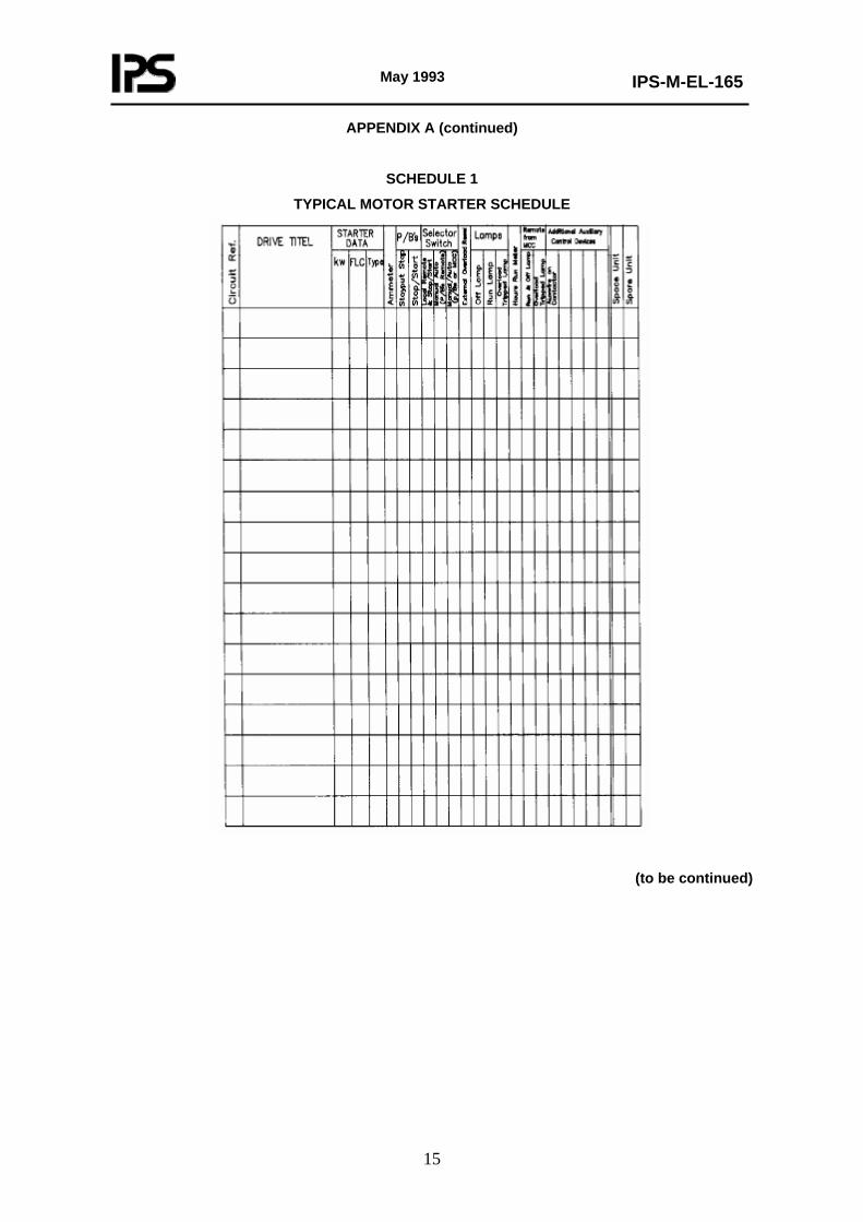
Note: The dimensions of bus ducting shall be agreed. - DETAILS OF MOTOR STARTERS (See Schedule 1) - DETAILS OF MOTOR (See Schedule 2) - DETAILS OF AIR BREAK SWITCHES, AIR BREAK DISCONNECTORS AND FUSE COMBINATION UNITS (See Schedule 3)
(to be continued)
May 1993
IPS-M-EL-165
15
APPENDIX A (continued)
SCHEDULE 1
TYPICAL MOTOR STARTER SCHEDULE
(to be continued)

May 1993
IPS-M-EL-165
16
APPENDIX A (continued)
SCHEDULE 2
TYPICAL DETAILS OF MOTORS TO BE STARTED
CIRCUIT REF.
DRIVE TITTLE
MAXIMUM RATING
CONTINU -OUS K.W.
No. OF POLES
CODE LETTER KVA/HP
DRIVEN EQUIPMENT
RUN UP TIME
SECONDS
POWER FACTOR
OF MOTOR
%
NOTES
(to be continued)

May 1993
IPS-M-EL-165
17
APPENDIX A (continued)
SCHEDULE 3
DETAILS OF AIR BREAK SWITCHES, AIRBREAK DISCONNECTORS AND FUSE COMBINATION UNITS TO BE INCORPORATED IN MCC
CIRCUIT
REF. DESCRIPTION
OF SWITCHING
DEVICE
No. OF POLES
SWITCHED OR
LINKED NEUTRAL
CURRENT PATTING
AMPS
VOLTAGE VOLTS
UTILIZATION CATEGORY
No. OF AUXILIARY CONTACTS

May 1993
IPS-M-EL-165
18
APPENDIX B
LIST OF DRAWINGS , DOCUMENTS , MANUALS AND CERTIFICATES TO BE SUBMITTED BY MANUFACTURER /SUPPLIER IN NUMBERS AND THE TIMES INDICATED BELOW:
CERTIFIED INFORM. REQ. WITH ORDER
N0. OF COPIES DESCRIPTION REQUIRED
WITH QUATATION REPRO-
DICIBLES PRINTED MATTER
NUMBER OF WEEKS AFTER
ORDER
NUMBER OF WEEKS
BEFORE DELIVERY
A DRAWING AND OTHER DOCUMENTS:
a) ELECTRICAL EQUIPMENT: 1. DIMENSIONED OUTLINES AND FOUNDATION
DETAILS
INCLUDING: CABLE ENTRIES AND CLEARANCES 2. DETAILS AND CROSS-SECTIONAL
ARRANGEMENT
3. MOUNTING DETAILS 4. PERFORMANCE DATA (TYPICAL) 5. PARTS / MATERIAL LIST 6. RELEVANT CATALOGUES 7. NAME PLATES 8. LIST OF FINAL LABELS b) TERMINATION: 1. CONNECTION DIAGRAM 2. TERMINAL BOX ARRANGEMENT 3. CONNECTION AND TERMINAL DESIGNATION c) ELECTRICAL REFERENCE DOCUMENTS: 1. GENERAL DESCRIPTION 2. EQUIPMENT SPECIFICATION 3. PERFORMANCE DATA (ACTUAL) 4. DRAWINGS / PARTS / MATERIALS LIST
B INSTRUCTION MANUALS : (FOR ALL REQUIRED ITEMS)
1. INSTALLATION, COMMISSIONING AND INSPECTION
2. OPERATION AND MAINTENANCE
C SPARE PARTS REQUIREMENTS:
1. ILLUSTRATED SPARE PARTS 2. RECOMMENDED COMMISSIONING SPARE LIST 3. RECOMMENDED SPARES FOR THREE YEARS
OPARATION
D CERTIFICATION: 1. PERFORMANCE TEST, MATERIALS
CERTIFICATES AND
CURVES
May 1993
IPS-M-EL-165
19
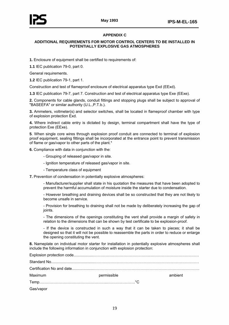
APPENDIX C
ADDITIONAL REQUIREMENTS FOR MOTOR CONTROL CENTERS TO BE INSTALLED IN POTENTIALLY EXPLOSIVE GAS ATMOSPHERES
1. Enclosure of equipment shall be certified to requirements of:
1.1 IEC publication 79-0, part 0.
General requirements.
1.2 IEC publication 79-1, part 1.
Construction and test of flameproof enclosure of electrical apparatus type Exd (EExd).
1.3 IEC publication 79-7, part 7. Construction and test of electrical apparatus type Exe (EExe).
2. Components for cable glands, conduit fittings and stopping plugs shall be subject to approval of "BASEEFA" or similar authority (U.L.,P.T.b.).
3. Ammeters, voltmeter(s) and selector switches, shall be located in flameproof chamber with type of explosion protection Exd.
4. Where indirect cable entry is dictated by design, terminal compartment shall have the type of protection Exe (EExe).
5. When single core wires through explosion proof conduit are connected to terminal of explosion proof equipment, sealing fittings shall be incorporated at the entrance point to prevent transmission of flame or gas/vapor to other parts of the plant.*
6. Compliance with data in conjunction with the:
- Grouping of released gas/vapor in site.
- Ignition temperature of released gas/vapor in site.
- Temperature class of equipment
7. Prevention of condensation in potentially explosive atmospheres:
- Manufacturer/supplier shall state in his quotation the measures that have been adopted to prevent the harmful accumulation of moisture inside the starter due to condensation.
- However breathing and draining devices shall be so constructed that they are not likely to become unsafe in service.
- Provision for breathing to draining shall not be made by deliberately increasing the gap of joints.
- The dimensions of the openings constituting the vent shall provide a margin of safety in relation to the dimensions that can be shown by test certificate to be explosion-proof.
- If the device is constructed in such a way that it can be taken to pieces; it shall be designed so that it will not be possible to reassemble the parts in order to reduce or enlarge the opening constituting the vent.
8. Nameplate on individual motor starter for installation in potentially explosive atmospheres shall include the following information in conjunction with explosion protection:
Explosion protection code...................……………………………………….………………………………
Standard No.........................................………………………………………………………………………
Certification No and date.....................……………………………………………………………………….
Maximum permissible ambient
Temp……………………………………………..………………….°C
Gas/vapor
May 1993
IPS-M-EL-165
20
group.....………………………………………………………..............................
Maximum surface temperature of equipment...........................................................°C
Certification authority and mark :
………………………………………….............................................................
Trade agent mark....................................…………………………………….....
Notes:
1) Requirements of Clause 6.11 of this Standard Specification shall also be implemented where applicable.
2) When flame path trap is provided, its full details shall be given by manufacturer/supplier.

May 1993
IPS-M-EL-165
21
ATTACHMENTS (General)
ATTACHMENT 1
ENVIRONMENTAL CONDITIONS
1.1 Site elevation : ----- meters above sea level.
1.2 Maximum ambient air temperature : ----- degrees centigrade. (Bare metal directly exposed to the sun can at times reach a surface temperature of -------- degrees centigrade.
1.3 Minimum air temperature : --------- degrees centigrade.
1.4 Relative humidity : --------- percent.
1.5 atmosphere : saliferrous, dusty corrosive and subject to dust storms with concentration of 70 - 1412 mg/cubic meter, H2S may be present, unless otherwise specified in data sheet.
1.6 Lightning storm isoceraunic level : --------- storm days/year.
1.7 Maximum intensity of earthquake ---------- richters.
Note:
Blanks to be filled by client.

May 1993
IPS-M-EL-165
22
ATTACHMENT 2
INSPECTION, QUALITY CONTROL AND QUALITY RECORDS
2.1 Inspection, Quality Control
2.1.1 The purchaser’s inspector, or his authorized representative shall have free access to the manufacturing plant engaged in the manufacture of the equipment, to carry out necessary inspection at any stage of work.
2.1.2 Inspection may include the visit to quality control laboratories, work shops, testing bay etc.
2.1.3 The supplier shall make available technical data, test pieces and samples that the purchaser’s representative may require for verification in conjunction with pertinent equipment.
If required the supplier shall forward the same to any person or location that the purchaser’s representative may direct.
2.2 Quality Records
2.2.1 The supplier shall maintain appropriate inspection and test records to substantiate conformance with specified requirements.
2.2.2 Quality record shall be legible and relevant to the product involved.
2.2.3 Quality records that substantiate conformance with the specified requirements, shall be retained by manufacturer and made available on request by purchaser.
2.2.4 The supplier shall establish and maintain procedure for identification collection, indexing, filing, storage, maintenance and disposition of quality records.
2.2.5 The supplier shall submit to purchaser: reports, test schedules, and test certificates (in ----- copies) on completion of tests.
Note:
blanks to be filled by client.

May 1993
IPS-M-EL-165
23
ATTACHMENT 3
(GENERAL)
TESTS AND CERTIFICATION
3.1 General Requirements
3.1.1 Test procedure as proposed by the supplier shall be agreed upon, and approved by the purchaser before any test is carried out.
3.1.2 Purchaser may require witnessed tests to be carried out in the presence of his nominated representative who should be informed at least ----- weeks in advance of the date of the tests and confirmed ----- weeks before the tests.
3.1.3 Test certificates and test reports shall refer to the serial No. of the equipment tested and must bear the purchaser’s name, order No. and manufacturer’s name and seal. The certificates shall be approved by the purchaser before shipment instruction are given.
3.1.4 Approval by the purchaser’s inspector or representative shall not relieve the vendor of his commitments under the terms of this specification or any associated order.
3.1.5 The equipment may be rejected if measurement and inspection reveal any discrepancies between quoted figures resulting in purchase order and those measured actually.
3.1.6 Any charges incurred by the tests quoted under heading of specific requirements for tests to be quoted as a separate item and are not to be included in the cost of the equipment.
Note:
Blanks to be filled by client.

May 1993
IPS-M-EL-165
24
ATTACHMENT 4
PACKING
4.1 Equipment must be carefully packed to provide necessary protection during transit to destination and shall be in accordance with any special provision contained in the order.
4.2 Special attention must be given to protection against corrosion during transit, and silica gel or similar dehydrating compound shall be enclosed.
4.3 The method of cleaning preserving and the details of packing including moisture elimination, cushioning, blocking and crating shall be such that to protect the product against all damages or defects which may occur during handling, sea shipment to the port and rough road haulage to site and extended tropical open air storage generally as client general conditions of purchase see Attachment 10.
4.4 All bright and machined parts must be given the protection against corrosion.
4.5 Ancillary items forming an integral part of the equipment should be packed preferably in a separate container if the equipment is normally cased or crated.
Alternatively the ancillary items should be fixed securely to the equipment and adequate precautions taken to ensure that the item do not come loose in transit or be otherwise damaged.
4.6 The supplier shall provide methods of handling to prevent damage and or deterioration during transit.
4.7 Where deemed necessary each shipping section shall be furnished with removable steel angles.
4.8 The requirements of above items shall not relieve the supplier of any of his responsibilities and his obligations for delivery of equipment in a sound undamaged and operable conditions at site.
4.9 Identification For Shipment
The marking and labels of products should be legible, durable and in accordance to specification.
Identification should remain intact from the time of initial despatch at work to the final destination.
Marking shall be adequate for identifying a particular equipment in the event that a recall or inspection becomes necessary.

May 1993
IPS-M-EL-165
25
ATTACHMENT 5
SHIPMENT
5.1 Motor control center package shall be provided with a permanently attached readily visible identification tag(s) bearing the equipment number of the motor starter(s) to which it belongs.
5.2 The greatest care must be taken to ensure that shipping and associated documents with exact description for custom release are accompanied with the shipment.
May 1993
IPS-M-EL-165
26
ATTACHMENT 6
GUARANTEE
6.1 Clearance of Defects
The supplier shall guarantee his equipment during commissioning and for one year operation starting from the completion of seven days continuous service test in site at full load against the following defects:
- All operational defects
- All material defects
- All constructional and design defects
6.2 Replacement of Defective Parts
All defective parts shall be replaced by the supplier in the shortest possible time free of charge including dismantling reassembling at site and all transportation cost. The above mentioned period shall not however be longer than 18 months from the date of dispatch from the manufacturer’s works.
6.3 Supply of Spare Parts
Furthermore the supplier shall guarantee the provision of spare parts to the purchaser for a minimum period of ----- years from the date of despatch.
6.4 After Sale Technical Services
6.4.1 Commissioning
6.4.1.1 The supplier shall quote if required for the services of competent engineer(s) and or technician(s) to assist in installation commissioning and testing of the equipment at site on a per diem basis.
6.4.1.2 The quoted rates shall be irrespective of duration and frequency and the supplier shall guarantee the services of the engineer(s) and technician(s) on the specified date within a minimum of ----- weeks advance notice by the purchaser.
6.4.2 Training
6.4.2.1 The purchaser may require the supplier to arrange for training of his personnel in the manufacturing plant and or in site for the operation and maintenance of the equipment offered.
6.4.2.2 The supplier shall quote (if required) for the cost of any of above mentioned services on a per person per diem basis. The program for the training shall be prepared by mutual agreement. An advance notice of ----- weeks minimum, is required by purchaser for the commencement of training program.
Note:
Blanks to be filled by client.

May 1993
IPS-M-EL-165
27
ATTACHMENT 7
SPARE PARTS
7.1 All spare parts shall comply with the same standards, specification and tests of the original equipment and shall be fully interchangeable with the original parts without any modification at site.
7.2 They shall be correctly marked in accordance with client reference and manufacturer part numbers, giving also the purchaser’s order number.
7.3 Spare parts shall be preserved to prevent deterioration during shipment and storage in humid tropical climate.
7.4 List of recommended spare parts and interchangeability with spare parts of similar equipment shall be submitted by supplier.
May 1993
IPS-M-EL-165
28
ATTACHMENT 8
LANGUAGE
8.1 All correspondence drawings, documents, certificates, including testing operation and maintenance manuals and spare part lists etc. shall be in English.
8.2 Offers in other languages will not be considered.
May 1993
IPS-M-EL-165
29
ATTACHMENT 9
COORDINATION RESPONSIBILITIES WITH OTHERS
9.1 In case the equipment ordered should be mounted on, aligned, connected, adjusted, or tested with the equipment of other manufacturer(s) the supplier shall contact directly the said manufacturer(s) and supply and obtain all dimensional and technical informations and arrange for any interconnecting equipment and combined test that may be required.
9.2 The supplier shall be responsible for correct and timely communication with the said manufacturer(s) and for any delay and/or cost claims arising from such communications.
9.3 Copies of all correspondence should be sent to purchaser.
9.4 The name and address of the manufacturer(s) will be given as soon as their orders have been confirmed.

May 1993
IPS-M-EL-165
30
ATTACHMENT 10
GENERAL CONDITIONS OF PURCHASE
This Document will be submitted by purchaser at the time of ordering.
May 1993
IPS-M-EL-165
31
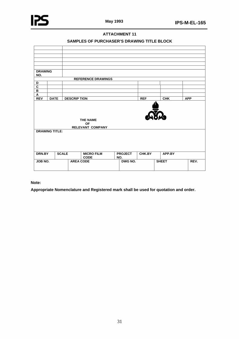
ATTACHMENT 11
SAMPLES OF PURCHASER’S DRAWING TITLE BLOCK DRAWING NO.
REFERENCE DRAWINGS D C B A REV DATE DESCRIP TION REF CHK APP
THE NAME OF RELEVANT COMPANY DRAWING TITLE: DRN.BY SCALE MICRO FILM
CODE PROJECT NO.
CHK.BY APP.BY
JOB NO. AREA CODE DWG NO. SHEET REV.
Note:
Appropriate Nomenclature and Registered mark shall be used for quotation and order.

May 1993
IPS-M-EL-165
32
ATTACHMENT 12
INSTRUCTIONS OF PURCHASER ABOUT PERTINENT DRAWINGS
12.1 Purchaser’s drawing title block, "the sample of which is given in Attachment 11 shall be shown in the right lower corner of the drawings.
12.2 Drawings are to be protected and packed. Negatives must be dispatched in a strong card board cylinder.
12.3 Drawings must be rolled and not folded.
12.4 All drawings, documents and literatures shall be forwarded under cover of a fully detailed letter to purchaser whose addresses are given in Attachment 14.
Note:
Blank to be filled by client.

May 1993
IPS-M-EL-165
33
ATTACHMENT 13
MATERIAL, LAYOUT AND LETTERING OF LABELS
Label material to be "Traffolite" 5 mm. Thick having two outer layers.
Letter to be engraved into the white layer to give black lettering on a white background.
LETTER TYPE TYPE HEIGHT WIDTH
mm STROKE CASE LETTERS / 25 mm SAMPLE
A 5 WIDE LIGHT UPPER CASE 7½ ± 1.2mm. TOL ABCDEFGHIJKLM B 5 WIDE HEAVY ײ ײ 7½ ± 1.2mm. TOL C 5 NARROW LIGHT ײ ײ 11 ± 1.2mm. TOL D 5 NARROW HEAVY ײ ײ 11 ± 1.2mm. TOL E 3 WIDE LIGHT ײ ײ 10 ± 1.2mm. TOL F 3 WIDE HEAVY ײ ײ 10 ± 1.2mm. TOL G 3 NARROW LIGHT ײ ײ 15 ± 1.2mm. TOL H 10 WIDE HEAVY ײ ײ 3½ j 12 WIDE HEAVY ײ ײ 2½
Note:
Height is in millimeters.
(to be continued)

May 1993
IPS-M-EL-165
34
ATTACHMENT 13 (continued)
LAYOUTS
Note:
All dimensions are given in mm.
min ≡minimum
May 1993
IPS-M-EL-165
35
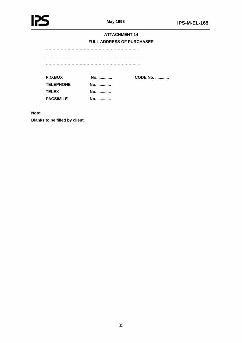
ATTACHMENT 14
FULL ADDRESS OF PURCHASER
…………………………………………………………...
…………………………………………………………....
…………………………………………………………....
P.O.BOX No. ............ CODE No. ............
TELEPHONE No. ............
TELEX No. ............
FACSIMILE No. ............
Note:
Blanks to be filled by client.