material quality assurance risk assessment quality assurance risk assessment prof. ... table 7.1....
TRANSCRIPT
STATE HIGHWAY ADMINISTRATION
RESEARCH REPORT
Material Quality Assurance Risk Assessment
PROF. DIMITRIOS GOULIAS SAHAND KARIMI
UNIVERSITY OF MARYLAND
Project number SP909B4K
FINAL REPORT
January 22, 2013
MD-13-SP909B4K
Martin O’Malley, Governor Anthony G. Brown, Lt. Governor
Darrell B. Mobley, Acting Secretary Melinda B. Peters, Administrator

The contents of this report reflect the views of the author who is responsible for the facts and the accuracy of the data presented herein. The contents do not necessarily reflect the official views or policies of the Maryland State Highway Administration. This report does not constitute a standard, specification, or regulation.
Technical Report Documentation Page
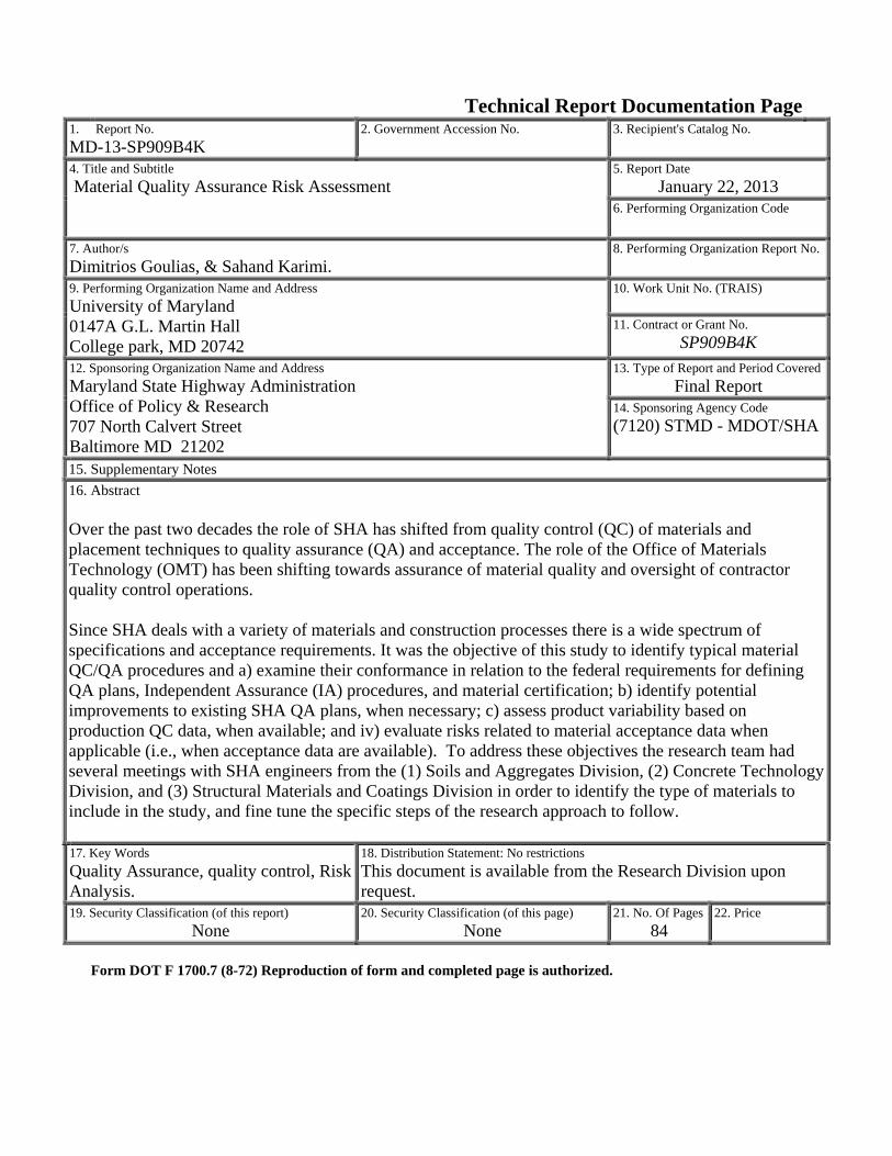
1. Report No. MD-13-SP909B4K
2. Government Accession No. 3. Recipient's Catalog No.
4. Title and Subtitle Material Quality Assurance Risk Assessment
5. Report Date January 22, 2013
6. Performing Organization Code
7. Author/s Dimitrios Goulias, & Sahand Karimi.
8. Performing Organization Report No.
9. Performing Organization Name and Address University of Maryland 0147A G.L. Martin Hall College park, MD 20742
10. Work Unit No. (TRAIS) 11. Contract or Grant No.
SP909B4K 12. Sponsoring Organization Name and Address Maryland State Highway Administration Office of Policy & Research 707 North Calvert Street Baltimore MD 21202
13. Type of Report and Period CoveredFinal Report
14. Sponsoring Agency Code (7120) STMD - MDOT/SHA
15. Supplementary Notes 16. Abstract Over the past two decades the role of SHA has shifted from quality control (QC) of materials and placement techniques to quality assurance (QA) and acceptance. The role of the Office of Materials Technology (OMT) has been shifting towards assurance of material quality and oversight of contractor quality control operations. Since SHA deals with a variety of materials and construction processes there is a wide spectrum of specifications and acceptance requirements. It was the objective of this study to identify typical material QC/QA procedures and a) examine their conformance in relation to the federal requirements for defining QA plans, Independent Assurance (IA) procedures, and material certification; b) identify potential improvements to existing SHA QA plans, when necessary; c) assess product variability based on production QC data, when available; and iv) evaluate risks related to material acceptance data when applicable (i.e., when acceptance data are available). To address these objectives the research team had several meetings with SHA engineers from the (1) Soils and Aggregates Division, (2) Concrete Technology Division, and (3) Structural Materials and Coatings Division in order to identify the type of materials to include in the study, and fine tune the specific steps of the research approach to follow. 17. Key Words Quality Assurance, quality control, Risk Analysis.
18. Distribution Statement: No restrictions This document is available from the Research Division upon request.
19. Security Classification (of this report) None
20. Security Classification (of this page) None
21. No. Of Pages 84
22. Price
Form DOT F 1700.7 (8-72) Reproduction of form and completed page is authorized.
i
University of Maryland, College Park Department of Civil and Environmental Engineering
Material Quality Assurance Risk Assessment
Final Research Report
Maryland State Highway Administration
Research Project SP909B4K
Prof. Dimitrios Goulias (PI)
Sahand Karimi (Graduate Research Assistant)
July 12, 2012 Rev. October 27, 2012
Rev. December 12, 2012
ii
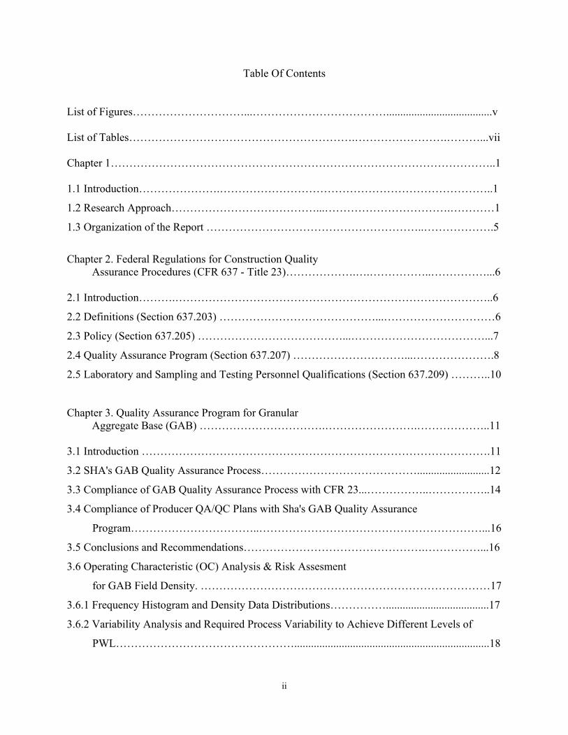
Table Of Contents List of Figures…………………………...………………………………......................................v List of Tables…………………………………………………….…………………….………...vii Chapter 1…………………………………………………………………………………………..1 1.1 Introduction………………….………………………………………………………………..1
1.2 Research Approach…………………………………...…………………………….…………1
1.3 Organization of the Report …………………………………………………..……………….5
Chapter 2. Federal Regulations for Construction Quality Assurance Procedures (CFR 637 - Title 23)……………….….……………..……………...6 2.1 Introduction……….…………………………………………………………………………..6
2.2 Definitions (Section 637.203) ……………………………………...…………………………6
2.3 Policy (Section 637.205) …………………………………...………………………………...7
2.4 Quality Assurance Program (Section 637.207) …………………………...………………….8
2.5 Laboratory and Sampling and Testing Personnel Qualifications (Section 637.209) ………..10
Chapter 3. Quality Assurance Program for Granular Aggregate Base (GAB) …………………………….…………………….………………..11 3.1 Introduction ………………………………………………………………………………….11
3.2 SHA's GAB Quality Assurance Process……………………………………..........................12
3.3 Compliance of GAB Quality Assurance Process with CFR 23...……………..……………..14
3.4 Compliance of Producer QA/QC Plans with Sha's GAB Quality Assurance
Program……………………………..……………………………………………………...16
3.5 Conclusions and Recommendations………………………………………….……………...16
3.6 Operating Characteristic (OC) Analysis & Risk Assesment
for GAB Field Density. ……………………………………………………………………17
3.6.1 Frequency Histogram and Density Data Distributions…………….....................................17
3.6.2 Variability Analysis and Required Process Variability to Achieve Different Levels of
PWL…………………………………………......................................................................18
iii
3.6.3 Operation Characteristics (OC) Analysis & Risks Assessment……………………………19
Chapter 4 Precast Concrete Quality Assurance Program (for Drainage Structures)……..……...21 4.1 Introduction………………………………………………………………………….............21
4.2 Precast Concrete Quality Assurance Process for Drainage Structures……………………...21
4.3 Precast Concrete Quality Assurance Inspection Manual………………………………….....22
4.4 Compliance of Precast Concrete Quality Assurance Program with CFR 23….....….……….23
4.5 Compliance of Producer QA/QC Manual With SHA's Precast Concrete Quality Assurance
Inspection Manual…………………………………………………………………….........24
4.6 Conclusions and Recommendations ………………………………………………..……….25
4.7 Variability Analysis of Producers' Precast Concrete Quality……………………….……….26
4.7.1 Rinker Pipe Precast Concrete Plant………………………………………..........................26
4.7.2 Hanson Pipe & Precast Concrete Plant………………………………………….…………39
Chapter 5. Structural Steel Quality Assurance Program…………………………………………50 5.1 Introduction………………………………………………………………………….............50
5.2 Quality Assurance Process for Structural Steel……………………………….……………..51
5.3 SHA QA Process & Fhwa Standard 104a On Recommended QC Plan Practice…………..56
5.4 SHA QA Process & CFR 23.637……………………………..……………………………56
5.5 Compliance of Producer QA/QC Manual with SHA's Quality Control Plan Guidelines …..57
5.6 Conclusions and Recommendations………………………………………………….……...59
Chapter 6. Rebar Certification Program………………………………………………………...60 6.1 Introduction………………………………………………………………………….............60
6.2 Rebar Certification Program…………………………………………………………………60
6.3 SHA QA Inspection Process & CFR 23.637……………………………..………………….62
6.4 Compliance of Producer QA/QC Manual with SHA's Quality Control Plan Guidelines…....63
6.5 Conclusions and Recommendations…………………………………………………………63
Chapter 7. Coatings Certification Program………………………………………………..……..65 7.1 Introduction…………………………………………………………………………………..65
iv
7.2 Coatings Certification Program……………………………………………………………...65
7.3 Compliance of Producer/Supplier QA/QC Manual with SHA's Quality Control Plan
Guidelines………………………………………………….................................................69
7.4 Conclusions and Recommendations……………….………………………………………...69
Chapter 8. Neoprene Strip Seal Certification Program…………………………………………..73 8.1 Introduction……………………………………………………………………………….….73
8.2 Review and Recommendations………………………………………………….………..….73
Chapter 9 Summary, Conclusions & Recommendations ………………………………………..75 9.1 Summary…………………………………………………………………...………………...75
9.2 Conclusions & Recommendations………………………………………………….………..75
9.3 Implementation & Benefits…………………………………………………………………..82
References………………………………………………………………………………………..83
v
LIST OF FIGURES Figure 1.1. Example of OC curves for assessing Contactor and Agency Risks in Function to
Sample Size and AQL, RQL………………………………………………………….4 Figure 3.1. QA Density Data Histogram for ICC………………………………………………..17 Figure 3.2. QC Density Data Histogram for ICC………………………………………………..18 Figure 3.3. OC Analysis for ICC Density ata…...…………………………………………….....20 Figure 4.1. Control Chart for Mix 4000 CY, 7 Day Strength Data……………………………...27 Figure 4.2. Control Chart for Mix 4000 CY, 28 Day Strength Data…………………………….28 Figure 4.3. Control Chart for Mix 4000 MM, 7 Day Strength Data……………………………..29 Figure 4.4. Control Chart for Mix 4000 MM, Day 28 Strength Data……………………………29 Figure 4.5. Control Chart for Mix 4000 MM Big Bore, Day 7 Strength
Data…………………………………………………………………………………..30 Figure 4.6. Control Chart for Mix 4000 CY, 28 Day Strength Data…………………………….30 Figure 4.7. Control Chart for Mix 4000 WC, 7 Day Strength Data……………………………..31 Figure 4.8. Control Chart for Mix 4000 WC, 28 Day Strength Data ……………………………32 Figure 4.9. Control Chart for Mix 6000 CY, 7 Day Strength Data……………………………...32 Figure 4.10. Control Chart for Mix 6000 CY, 28 Day Strength Data…………………………...33 Figure 4.11. Control Chart for Mix 6000 MM, 7 Day Strength Data ……………………………34 Figure 4.12. Control Chart for Mix 6000 MM, 28 Day Strength Data…………………………..34 Figure 4.13. Relative Frequency Histogram (n=30) for Mix 4000 CY, 7 Day Strength
Data………………………………………………………………………………....35 Figure 4.14. Relative Frequency Histogram (n=26) for Mix 4000 CY, 28 Day Strength
Data…………………………………………………………………………………35 Figure 4.15. Relative Frequency Histogram (n=28) for Mix 4000 MM, 7 Day Strength
Data…………………………………………………………………………………36 Figure 4.16. Relative Frequency Histogram (n=28) for Mix 4000 MM, 28 Day Strength
Data…………………………………………………………………………………36 Figure 4.17. Relative Frequency Histogram (n=27) for Mix 4000 MM Big Bore, 7 Day
Strength Data……………………………………………………………………….36 Figure 4.18. Relative Frequency Histogram (n=24) for Mix 4000 MM Big Bore, 28 Day
Strength Data…………………………………………………………………….....37 Figure 4.19. Relative Frequency Histogram (n=30) for Mix 4000 WC, 7 Day Strength
Data……………………………………………………………………………..…..37 Figure 4.20. Relative Frequency Histogram (n=27) for Mix 4000 WC, 28 Day Strength
Data…………………………………………………………………………………37 Figure 4.21. Relative Frequency Histogram (n=28) for Mix 6000 CY, 7 Day Strength
Data………………………………………………………………………………....38 Figure 4.22. Relative Frequency Histogram (n=23) for Mix 6000 CY, 28 Day Strength
Data…………………………………………………………………………………38 Figure 4.23. Relative Frequency Histogram (n=30) for Mix 6000 MM, 7 Day Strength
Data………………………………………………………………………… …….. 38 Figure 4.24. Relative Frequency Histogram (n=27) for Mix 6000 MM, 28 Day Strength
Data…………………………………………………………………………………39 Figure 4.25. Control Chart for 2008 SCC MIX#1 - 7 Day Strength Data……………………….41 Figure 4.26. Control Chart for 2008 SCC MIX#1 - 28 Day Strength Data ……………………..42
vi
Figure 4.27. Control Chart for 2008 SCC MIX#1 - 7 Day Average/Paired Strength Data……...43 Figure 4.28. Control Chart for 2008 SCC MIX#1 - 28 Day Average/Paired Strength Data…….44 Figure 4.29. Control Chart for 2008 SCC MIX#1 - 7 Day Strength Data/ R - Values
………………………………………………………………………………………45 Figure 4.30. Control Chart for 2008 SCC MIX#1 - 28 Day Strength Data/R-Values
………………………………………………………………………………………45 Figure 4.31. Relative Frequency Histogram for 2008 SCC MIX#1 - 7 Day Strength Data
(Individual Values, n=46) ..………………………………………………………...46 Figure 4.32. Relative Frequency Histogram for 2008 SCC MIX#1 - 28 Day Strength Data
(Individual Values, n=30) …………………………………………………………..47 Figure 4.33. Relative Frequency Histogram for 2008 SCC MIX#1 - 7 Day Paired/Average
Strength Values (n=23) …………………………………………………………….47 Figure 4.34. Relative Frequency Histogram for 2008 SCC MIX#1 - 28 Day Paired/Average
Strength Values (n=14) …………………………………………………………….48 Figure 4.35. Bimodal Distribution Example for 2008 SCC MIX#1 - 7 Day Strength Data
(Individual Values) (n=46) ………………………………………………………....48 Figure 4.36. Bimodal Distribution Example for 2008 SCC MIX#1 - 7 Day Paired/Average
Strength Values (n=23) ………………………………………………………….…49
vii
LIST OF TABLES Table 1.1 Risk Levels Suggested by AASHTO R-9………………………………………………4 Table 3.1. Characteristics of QA and QC Data for ICC…………………………………………18 Table 3.2. Required Mean Field Density Value based on Current
Standard Deviation of QA Data……………………………………………………………19 Table 3.3. Required Reduction in Field Density Data Variability based on Field Mean Value of QA data (98.0%)…………………………………………..19 Table 3.4. Risk Values for ICC Individual Density Data………………………………………..20 Table 4.1. Concrete Mix Characteristics for Rinker Pipe Plant………………………………….27 Table 4.2. Normality Test Results for Rinker Pipe Concrete Mixtures….………………………39 Table 4.3. Statistical Characteristics of WC1……………………………………………………40 Table 4.4. Statistical Characteristics of WC2 …………………………………………………...40 Table 4.5. Statistical Characteristics of SCC MIX#1……………………………………………40 Table 4.6 Statistical Characteristics of Dry Cast RCP…………………………………………...42 Table 4.7. Statistical Characteristics of SCC MIX#1 (Paired Values)…………………………..43 Table 4.8. Statistical Characteristics of SCC MIX#1 (Range Values)…………………………..44 Table 7.1. Producers' Quality Control Procedures Review……………………………………...72
1
CHAPTER 1 1.1 INTRODUCTION Maryland State Highway Administration (SHA) is responsible for assuring that materials produced, supplied and placed on construction projects meet quality requirements set within material and construction specifications. Over the past two decades the role of SHA has shifted from quality control (QC) of materials and placement techniques to quality assurance (QA) and acceptance. This has placed more responsibility for quality during production on the contractor, producer and supplier. The Office of Materials Technology’s (OMT) role has been focusing towards assurance of material quality and oversight of contractor quality control operations. Such shift in responsibilities is attributed to the modern transition from method and end-results specifications towards performance specifications, and the adoption of Design-Build practice in construction. This shift eventually allows higher level of innovation and flexibility from the contractor, and lower involvement and resources from the agency. To adapt to such environment several materials acceptance specifications were revised. In some cases the revised specifications allow for the acceptance and payment of materials to be based on contractor, producer and/or supplier quality test results (QC and certification testing) with complimentary testing and inspection from SHA to verify results (QA). In other situations QA data are used for acceptance and rewards based on quality at delivery. Since SHA deals with a variety of materials and construction processes there is a wide spectrum of specifications and acceptance requirements. It was the objective of this study to identify typical material QC/QA procedures and a) examine their conformance in relation to the federal requirements for defining QA plans, Independent Assurance (IA) procedures, and material certification; b) identify potential improvements to existing SHA QA plans, when necessary; c) assess product variability based on production QC data, when available; and d) evaluate risks related to material acceptance data when applicable (i.e., when acceptance data are available). To address these objectives the research team had several meetings with SHA engineers from the (1) Soils and Aggregates Division, (2) Concrete Technology Division, and (3) Structural Materials and Coatings Division in order to identify the type of materials to include in the study, and fine tune the specific steps of the research approach to follow. 1.2 RESEARCH APPROACH To address these objectives the following steps and analysis were undertaken by the research team composed of Drs. Goulias and Schwartz and Mr. Karimi. Task 1 Review of Prior Stewardship A literature review on the methods of acceptance of materials was conducted. Specifically, issues related to material certification, quality control practices, impact of sample size, evaluation and assessment of agency and contractor risks and use of Operational Characteristic curves, and definition/ evaluation of pay factors, were examined (Burati et. al., 2005, Burati et. al., 2006, Parker et.al. 2007, Villiers et. al. 2003, Weed et. al. 1996). Also the recent Federal Highway Administration (FHWA) stewardship reviews and recommendations on the material quality
2
assurance program were reviewed and the relevant points are included in chapter 2. The research team then reviewed SHA’s QA and specification practice, including the methods and procedures identified in the Laboratory and Field Procedure Materials Manuals. This included material acceptance and prequalification practice, sampling and testing methods, frequency of testing for QC and QA/acceptance, and material certification standards for the selected materials: a) GAB, b) precast concrete for drainage elements, c) structural steel, d) rebars, e) coatings, and d) neoprene strip seals. Finally, the research team worked with OMT to identify strengths and opportunities with SHA's approach to material quality assurance, as outlined in the following sections Task 2. Examine Current Quality Assurance Procedures, Risks & Potential Improvements Objective of this review and analysis was to assess the existing methodology used by OMT to assure the quality of materials used on construction projects. Since different approaches are used to assure material quality, this assessment was organized by examining typical cases representing a specific quality assurance process (i.e., process control, quality assurance and material certification). Based on several meetings with SHA engineers and Q/A Representatives it was decided to address the following materials since they represent a distinct approach to quality evaluation and acceptance:
i) Graded Aggregate Base: In this case the QA process includes plant inspections and aggregate source approvals procedures that are based on QA audits, while field compaction/ density is based on an acceptance program.
ii) Precast concrete for drainage structures: drainage products are accepted based on: the Manufacturer’s certification that products meet specifications/ and requirements approved and verified by the following: (a) periodic quality assurance audits (b) annual plant inspections, (c) QC Plan requirements and review (by SHA QA representative), (d) visual inspection and material certification /verification upon jobsite delivery. Thus, while “acceptance program” is not considered by SHA on the characteristics and properties of these precast concrete drainage elements the QA program is based on QA audits.
iii) Structural Steel: In the case of structural steel the SHA quality assurance program is based on material certification through (a) annual plant inspections, and (b) periodic quality assurance audits.
iv) Rebars: The SHA quality assurance approach for rebars is primarily a material certification program and is based on a combination of: a) QC Plan (QCP) requirements and review, b) material certifications, and c) a rebar plant audit/ inspection to review whether the QCP elements and other handling and critical records are in place.
v) Coatings: The SHA quality assurance approach for coatings is primarily a source certification program and is based on a combination of: a) review and approval of a QC Plan (QCP), and b) QA audits to determine compliance with QC manual; it also includes c) random QA Verification sampling & testing to assure conformance with the SHA specifications.
vi) Neoprene Strip Seal: The SHA neoprene strip seal certification procedure is primarily a material certification program and is based on: a) material certification, and b)
3
periodic random verification sampling and testing to assess whether the produced material meets the required properties per specification. Such results are then used for accepting a lot or batch.
For each case the respective QA and QC documents and data were reviewed and discussed with SHA engineers and QA representatives throughout the duration of the project. The specific documents, reviews and findings are included in Chapters 3, 4, 5, 6, and 7. In specific cases the research team visited with SHA engineers and QA representatives specific production plants and sources to assess overall production and QC procedures. Specifically, two precast concrete plants were visited with SHA engineers and QA representatives from the Concrete Technology Division: 1) the Hanson Pipe & Precast plant in Jessup, MD, located at 7970 Waterloo Road, 20794, representing an older plant, and 2) the Rinker Pipe Plant in Frederick, MD,, located at 1751 Monocacy Blvd, 21701, representing a more modern plant with significant automation incorporated in production. Based on follow-up meetings with SHA engineers and QA representatives, it was decided to include in the analysis QC data from these two precast concrete plants for assessing production variability. The results are presented in chapter 4. Producers’ QC plans for the remaining materials were examined as well and the findings are included in the corresponding chapters' related to each material.
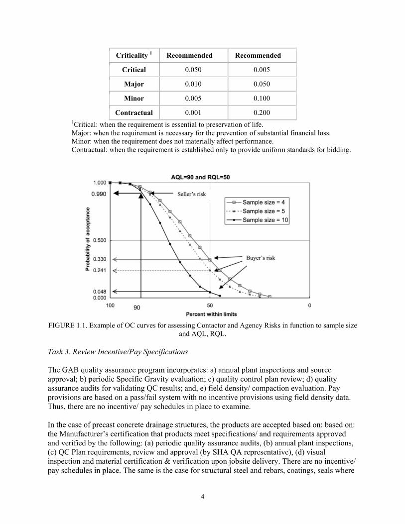
Similarly for the GAB case, it was decided to visit and examine the production from two quarries, the Aggregate Industries Rockville Quarry and the Lafarge Texas Cockeysville Quarry. The QC plans from these quarries were examined and the findings are included in chapter 3. Also, for the GAB, field density data from the ICC Contract C AT3765C60 were provided by SHA for the analysis. Since these represent acceptance data, percent within limits (PWL) analysis were conducted, the Operating Characteristic (OC) curves were built, and finally the alpha and beta risk values (often identified as Type I (�) contractor, and Type II (�) agency risks) were calculated and analyzed in relation to sample size, similarly to the example showing in Figure 1.1 and based on the following definitions:
- Buyer’s risk (β), the probability that the agency would accept poor quality material; - Rejectable Quality Level (RQL), the level of quality that the material is unacceptable; - Seller’s risk (α), the probability that contractor’s/ seller’s good quality material may be
rejected; - Acceptable Quality Level (AQL), the level of quality that the material is fully
acceptable.
The results of these analyses are included in chapter 3. Using these Operation Characteristic Curves (OC), it was possible to examine with the current specification limits the impact of sampling sizes on the Type I and II risks. These risks can be compared to the recommended levels by AASHTO, Table 1.1, or any level of risks SHA desires to consider acceptable. This analysis could eventually lead SHA to examine the impact of: a) changing specification tolerances, b) reducing process variability, if possible, c) modifying sample size, or d) revising AQL and RQL, to meet expected risks levels. Figure 1.1 shows an example of such OC analysis using PWL and sample size, and relating AQL, and RQL with risks, while the results and findings from the actual field compaction for GAB as presented in Chapter 3.
Table 1.1 Risk Levels Suggested by AASHTO R-9
4
Criticality 1 Recommended � Recommended �
Critical 0.050 0.005
Major 0.010 0.050
Minor 0.005 0.100
Contractual 0.001 0.2001Critical: when the requirement is essential to preservation of life. Major: when the requirement is necessary for the prevention of substantial financial loss. Minor: when the requirement does not materially affect performance. Contractual: when the requirement is established only to provide uniform standards for bidding.
FIGURE 1.1. Example of OC curves for assessing Contactor and Agency Risks in function to sample size
and AQL, RQL. Task 3. Review Incentive/Pay Specifications The GAB quality assurance program incorporates: a) annual plant inspections and source approval; b) periodic Specific Gravity evaluation; c) quality control plan review; d) quality assurance audits for validating QC results; and, e) field density/ compaction evaluation. Pay provisions are based on a pass/fail system with no incentive provisions using field density data. Thus, there are no incentive/ pay schedules in place to examine. In the case of precast concrete drainage structures, the products are accepted based on: based on: the Manufacturer’s certification that products meet specifications/ and requirements approved and verified by the following: (a) periodic quality assurance audits, (b) annual plant inspections, (c) QC Plan requirements, review and approval (by SHA QA representative), (d) visual inspection and material certification & verification upon jobsite delivery. There are no incentive/ pay schedules in place. The same is the case for structural steel and rebars, coatings, seals where
5
the QA approach is primarily based on certification (rather than acceptance testing), and full payment is provided if there is compliance with the certification requirements.
Task 4 -Review of SHA's QA Programs and Compliance with Federal Regulations In this task the project team reviewed the various SHA's quality assurance plans for the construction materials included in the study and assessed whether they meet the federal requirements CFR 637, Title 23 of the "Code of Federal Regulations". These include requirements for sample techniques, guidelines on using contractor data, requirements for maintaining a central laboratory or use of consultants for IA and verification work, requirements for independent verification sampling, etc. The results of such review are included in Chapters 3, 4, 5, 6, 7, and 8. Task 5 - Recommendations & Final Report The findings from this study are included in Chapters 3, 4, 5, 6, 7 and 8, for each material, and summarized in Chapter 9. The recommendations include suggestions for improving the existing quality assurance processes for the set of materials that were examined in this SHA project (GAB, precast concrete for drainage elements, structural steel, rebars, coatings, and neoprene strip seals). The project team has discussed such recommendations throughout the project duration in meetings with SHA engineers from the three OMT Divisions involved in the study (Soils and Aggregates Division, Concrete Technology Division, Structural Materials and Coatings Division).
1.3 ORGANIZATION OF THE REPORT This first chapter presents the introduction, research objectives, the analysis approach and the organization of this report. Chapter 2 presents the federal regulations for construction QA procedures (CFR 637 - TITLE 23). Chapter 3 includes a detail description and the review of the GAB QA program, an assessment of its compliance to federal regulations, review of suppliers' QA/QC plans, conclusion and recommendations for improving the QA program and eventually production quality. It also includes the development of OC curves for field density acceptance data, production variability analysis, and evaluation of agency and contractor risks. Chapter 4 includes the description and review of the precast concrete QA program, an assessment of its compliance to federal regulations, review of producers' QA/QC manuals, conclusion and recommendations for improving the QA program and eventually production quality. It also includes an assessment of production variability using two producers' QC data. Chapter 5 includes the description and review of the structural steel QA program, appraisal of its compliance to federal regulations, review of producers' QA/QC manuals, conclusion and recommendations for QAP improvements. Chapter 6 includes the review of the rebar certification program, compliance assessment to federal regulations, review of producers' QA/QC manuals, and conclusion and recommendations. Chapter 7 examines the coatings certification program and its compliance to federal regulations, the review of producers' QA/QC manuals, and conclusion and recommendations. Finally, chapter 8 deals with the neoprene strip seal certification program, assessment of its compliance to federal regulations, and conclusions and recommendations.
6
CHAPTER 2. FEDERAL REGULATIONS FOR CONSTRUCTION QUALITY ASSURANCE PROCEDURES (CFR 637 - TITLE 23) 2.1 INTRODUCTION. The purpose of the federal regulations for construction quality assurance procedures (CFR 637 - Title 23) is to prescribe policies, procedures, and guidelines to assure the quality of materials and construction in all Federal-aid highway projects on the National Highway System. Such regulations were used to assess compliance of SHA quality assurance procedures for GAB, precast concrete for drainage products, structural steel, rebars, coatings, and neoprene strip seals. An overview of these regulations are included herein, with details on the definitions (section 637.203), policy (section 637.205), quality assurance program requirements (section 637.207), and the requirements for laboratory, sampling and testing, and personnel qualifications (section 637.209). 2.2 DEFINITIONS (SECTION 637.203) CFR 637.203 provides the following definitions pertinent to the QA procedures:
a) Acceptance program. All factors that comprise the State transportation department's (STD) determination of the quality of the product as specified in the contract requirements. These factors include verification sampling, testing, and inspection and may include results of quality control sampling and testing.
b) Independent assurance program. Activities that are an unbiased and independent evaluation of all the sampling and testing procedures used in the acceptance program. Testing used in the acceptance program which is performed in the STD's central laboratory would not be allowed by an independent assurance program.
c) Proficiency samples. Homogeneous samples that are distributed by AMRL/CCRl and tested by two or more laboratories. The test results are compared to assure that the laboratories are obtaining the same results.
d) Qualified laboratories. Laboratories that are capable as defined by appropriate programs established by each STD. As a minimum, the qualification program shall include provisions for checking test equipment and the laboratory shall keep records of calibration checks.
e) Qualified sampling and testing personnel. Personnel who are capable as defined by appropriate programs established by each STD.
f) Quality assurance. All those planned and systematic actions necessary to provide confidence that a product or service will satisfy given requirements for quality.
g) Quality control. All contractor/vendor operations and activities that are performed or conducted to fulfill the contract requirements.
h) Random sample. A sample drawn from a lot in which each increment in the lot has an equal probability of being chosen.
i) Vendor. A supplier of project-produced material that is not the contractor. j) Verification sampling and testing. Sampling and testing performed to validate the quality
of the product.
7
2.3 POLICY (SECTION 637.205) CFR 637.205 identifies the following policy for the various components and activities of a quality assurance program. (a) Quality assurance program. Each State transportation department (STD) shall develop a quality assurance program which will assure that the materials and workmanship incorporated into each Federal-aid highway construction project on the NHS are in conformity with the requirements of the approved plans and specifications, including approved changes. The program must meet the criteria in 637.207 (laboratory sampling and testing) and be approved by FHWA. (b) STD capabilities. The STD shall maintain an adequate, qualified staff to administer its quality assurance program. The State shall also maintain a central laboratory. The State's central laboratory shall meet the requirements in 637.209(a)(2).- AASHTO accredited laboratory. Since some states outsource their laboratory testing, such labs should meet the same requirements. (c) Independent assurance program. Independent assurance samples and tests or other procedures shall be performed by qualified sampling and testing personnel employed by the STD or its designated agent. (d) Verification sampling and testing. The verification sampling and testing are to be performed by qualified testing personnel employed by the STD or its designated agent, excluding the contractor and vendor. (e) Random samples. All samples used for quality control and verification sampling and testing shall be random samples.
Furthermore the key highlights of these policies and requirements include the following:
• QA program must meet criteria and requirements in 603.207 described next and including guidelines for any of the following, acceptance program, IA program, and material certification;
• Acceptance program shall specify: i) frequency, ii) location, and iii) attributes
guidelines;
• If QC data used in acceptance should: i) use qualified labs and personnel; ii) include verification testing through independent samples; iii) QC/QA testing evaluated by IA program; iv) consider dispute resolution;
• IA program shall: i) evaluate personnel and equipment; ii) cover sampling and testing procedures, and equipment; iii) identify frequency;
• Material Certification by project;
8
• STD shall maintain a central lab (AASHTO or comparable accredited and approved by FHWA). Any non-STD lab for verification, IA or dispute resolution testing should meet these requirements. (conflict of interest - non -STD labs should be involved only in one of verification, QC, IA, or dispute resolution testing).
• Independent assurance program shall be performed by qualified STD personnel or its agent.
• Verification sampling and testing are to be performed by qualified STD personnel or its agent, (excluding contractor and vendor)
• All samples shall be random samples
• Conflict of Interest: any qualified non-STD laboratory shall perform only one of the following types of testing on the same project: Verification testing, quality control testing, IA testing, or dispute resolution testing.
2.4 QUALITY ASSURANCE PROGRAM (SECTION 637.207) The relevant guidelines and requirements of CFR 637 for the development of a QA program are highlighted in this section. The federal requirements identify that each STD's quality assurance program shall provide for an acceptance program and an independent assurance (IA) program consisting of the following: (1) Acceptance program. (i) Each STD's acceptance program shall consist of the following:
(A) Frequency of sampling and testing for verification acceptance which will give general guidance to personnel responsible for the program and allow adaptation to specific project conditions and needs. (B) Identification of the specific location in the construction or production operation at which verification sampling and testing is to be accomplished. (C) Identification of the specific attributes to be inspected which reflect the quality of the finished product.
(ii) Quality control sampling and testing results may be used as part of the acceptance decision provided that:
(A) The sampling and testing has been performed by qualified laboratories and qualified sampling and testing personnel.
(B) The quality of the material has been validated by the verification sampling and testing. The verification testing shall be performed on samples that are taken
9
independently of the quality control samples. (C) The quality control sampling and testing is evaluated by an IA auditing program.
(iii) If the results from the quality control sampling and testing are used in the acceptance program, the STD shall establish a dispute resolution system. The dispute resolution system shall address the resolution of discrepancies occurring between the verification sampling and testing and the quality control sampling and testing. The dispute resolution system may be administered entirely within the STD. (iv) In the case of a design-build project on the National Highway System, warranties may be used where appropriate. (2) Independent Assurance (IA) program The IA program shall evaluate the qualified sampling and testing personnel and the testing equipment. The program shall cover sampling procedures, testing procedures, and testing equipment. Each IA program shall include a schedule of frequency for IA evaluation. The schedule may be established based on either a project basis or a system basis. The frequency can be based on either a unit of production or on a unit of time. (i) The testing equipment shall be evaluated by using one or more of the following: Calibration checks, split samples, or proficiency samples. (ii) Testing personnel shall be evaluated by observations and split samples or proficiency samples. (iii) A prompt comparison and documentation shall be made of test results obtained by the tester being evaluated and the IA tester. The STD shall develop guidelines including tolerance limits for the comparison of test results. (iv) If the STD uses the system approach to the IA program, the STD shall provide an annual report to the FHWA summarizing the results of the IA program. (3) Materials Certification The preparation of a materials certification shall be submitted to the FHWA Division Administrator for each construction project which is subject to FHWA construction oversight activities. Design- Build Projects In the case of a design-build project, the STD's quality assurance program should consider the specific contractual needs of the design-build project. All provisions related to the quality assurance program of this section are applicable to design-build projects.
10
2.5 LABORATORY AND SAMPLING AND TESTING PERSONNEL QUALIFICATIONS (SECTION 637.209) Regarding the laboratory and sampling and testing personnel qualifications the federal requirements include the following recommendations and requirements: (a) Laboratories.
(1) After June 29, 2000, all contractor, vendor, and STD testing used in the acceptance decision shall be performed by qualified laboratories, whether these are state or outsourcing laboratories.
(2) After June 30, 1997, each STD shall have its central laboratory accredited by the AASHTO Accreditation Program ASTM or a comparable laboratory accreditation program approved by the FHWA.
(3) After June 29, 2000, any non-STD designated laboratory which performs IA sampling and testing shall be accredited in the testing to be performed by the AASHTO Accreditation Program or a comparable laboratory accreditation program approved by the FHWA.
(4) After June 29, 2000, any non-STD laboratory that is used in dispute resolution sampling and testing shall be accredited in the testing to be performed by the AASHTO Accreditation Program or a comparable laboratory accreditation program approved by the FHWA.
(b) Sampling and testing personnel. After June 29, 2000, all sampling and testing data to be used in the acceptance decision or the IA program shall be executed by qualified sampling and testing personnel. (c) Conflict of interest. In order to avoid an appearance of a conflict of interest, any qualified non-STD laboratory shall perform only one of the following types of testing on the same project: Verification testing, quality control testing, IA testing, or dispute resolution testing.

11
CHAPTER 3. QUALITY ASSURANCE PROGRAM FOR GRANULAR AGGREGATE BASE (GAB) 3.1 INTRODUCTION The policies and regulations of the Code of Federal Regulations (CFR) title 23, used by Federal Highway Administration (FHWA) and described in chapter 2, were used in examining compliance of Maryland State Highway Administration’s GAB Quality Assurance program (version 2008 to 10) in relation to these requirements. Four different documents describing different components of Maryland State Highway Administration’s GAB Quality Assurance program were provided and considered in this review. These included:
1- Graded Aggregate Base (GAB) – Annual Plant Inspection Procedure 2- 6 Month Specific Gravity Check Procedure 3- GAB Quality Control Plan Review Procedures 4- Graded Aggregate Base: Quality Assurance Audit (split gradations)
The purpose of each document is as follows:
1- Graded Aggregate Base (GAB) – Annual Plant Inspection Procedure: Deals with the annual inspection of producers providing GAB to SHA and QA representatives and requires inspection once a year.
2- 6 Month Specific Gravity Check Procedure: Identifies the periodic evaluation of aggregate specific gravity for all state-approved GAB producing quarries.
3- GAB Quality Control Plan Review Procedures: Deals with the annual approval of QC plans for each GAB producer.
4- Graded Aggregate Base: Quality Assurance Audit (split gradation): dealing with evaluation of the plants' gradation to validate the producers Quality Control (QC) results through split gradation testing.
Additional guidelines for the GAB Quality Assurance program are provided in the SHA Materials Manual (SHA MM). These include plant and field sampling and testing frequencies as outlined in the SHA Frequency Guide (Chapter II, Tables 1-4) provides additional guidelines for plant and field sampling and testing. Furthermore, communication and feedback from SHA engineers and QA representatives as well as observations from a quarry site visit at the Aggregate Industry Travilah/Rockville Quarry (13900 Piney Meetinghouse Rd, Rockville, 20854, MD), provided further feedback on the GAB quality assurance program.
12
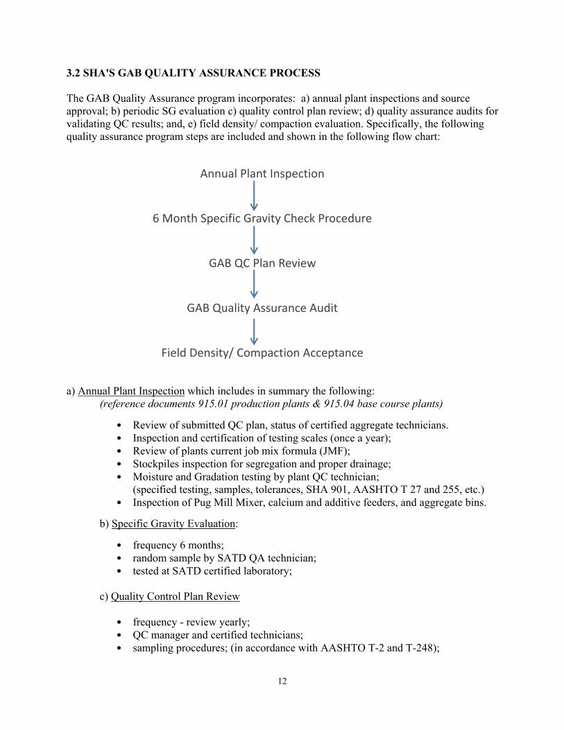
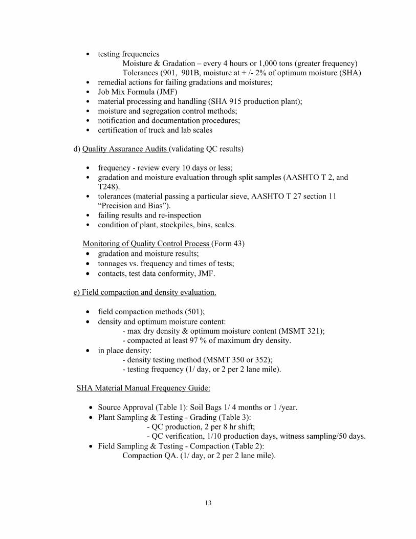
3.2 SHA'S GAB QUALITY ASSURANCE PROCESS The GAB Quality Assurance program incorporates: a) annual plant inspections and source approval; b) periodic SG evaluation c) quality control plan review; d) quality assurance audits for validating QC results; and, e) field density/ compaction evaluation. Specifically, the following quality assurance program steps are included and shown in the following flow chart: a) Annual Plant Inspection which includes in summary the following: (reference documents 915.01 production plants & 915.04 base course plants)
• Review of submitted QC plan, status of certified aggregate technicians. • Inspection and certification of testing scales (once a year); • Review of plants current job mix formula (JMF); • Stockpiles inspection for segregation and proper drainage; • Moisture and Gradation testing by plant QC technician;
(specified testing, samples, tolerances, SHA 901, AASHTO T 27 and 255, etc.) • Inspection of Pug Mill Mixer, calcium and additive feeders, and aggregate bins.
b) Specific Gravity Evaluation:
• frequency 6 months; • random sample by SATD QA technician; • tested at SATD certified laboratory;
c) Quality Control Plan Review
• frequency - review yearly; • QC manager and certified technicians; • sampling procedures; (in accordance with AASHTO T-2 and T-248);
Annual Plant Inspection
6 Month Specific Gravity Check Procedure
GAB QC Plan Review
GAB Quality Assurance Audit
Field Density/ Compaction Acceptance
13
• testing frequencies Moisture & Gradation – every 4 hours or 1,000 tons (greater frequency)
Tolerances (901, 901B, moisture at + /- 2% of optimum moisture (SHA) • remedial actions for failing gradations and moistures; • Job Mix Formula (JMF) • material processing and handling (SHA 915 production plant); • moisture and segregation control methods; • notification and documentation procedures; • certification of truck and lab scales
d) Quality Assurance Audits (validating QC results)
• frequency - review every 10 days or less; • gradation and moisture evaluation through split samples (AASHTO T 2, and
T248). • tolerances (material passing a particular sieve, AASHTO T 27 section 11
“Precision and Bias”). • failing results and re-inspection • condition of plant, stockpiles, bins, scales.
Monitoring of Quality Control Process (Form 43) • gradation and moisture results; • tonnages vs. frequency and times of tests; • contacts, test data conformity, JMF.
e) Field compaction and density evaluation.
• field compaction methods (501); • density and optimum moisture content:
- max dry density & optimum moisture content (MSMT 321); - compacted at least 97 % of maximum dry density.
• in place density: - density testing method (MSMT 350 or 352); - testing frequency (1/ day, or 2 per 2 lane mile).
SHA Material Manual Frequency Guide:
• Source Approval (Table 1): Soil Bags 1/ 4 months or 1 /year. • Plant Sampling & Testing - Grading (Table 3):
- QC production, 2 per 8 hr shift; - QC verification, 1/10 production days, witness sampling/50 days.
• Field Sampling & Testing - Compaction (Table 2): Compaction QA. (1/ day, or 2 per 2 lane mile).
14
3.3 COMPLIANCE OF GAB QUALITY ASSURANCE PROCESS WITH CFR 23 Based on CRF 23 - 637.207 each STD's quality assurance program shall provide for: i) an acceptance program, and ii) QA audits. In the case of GAB, plant inspections and aggregate source approvals procedures are based on QA audits, while field compaction/ density is based on an acceptance program basis. Specifically these QA components address the following characteristics/ requirements of CFR 23: I. Quality Assurance (QA) audits
A. Evaluation of Personnel & Equipment; Cover Sampling and Testing procedures, & Equipment
The various components of the GAB QA program, including (i) annual plant inspections and source approval, ii) periodic Specific Gravity evaluation, iii) quality control plan review, iv) quality assurance audits), provide considerations and guidelines for sampling and testing personnel and the testing equipment. Details on sampling and testing procedures, and testing equipment are identified. These issues are addressed in the following sections.
Annual Plant Inspection • reference to 915.01 - Production Plants: identifying aggregate storage and feeder
systems, measuring devices, production plant tolerances, sampling equipment, QC lab;
• reference to 915.04 - Base Course Plants: aggregate handling procedures; • certified aggregate technicians (QC plan). • testing scales; • job mix formula (JMF); • Stockpiles inspection; • Moisture and Gradation testing (specified testing and standards, samples,
tolerances) • Inspection of Pug Mill Mixer, calcium and additive feeders, and aggregate bins.
Specific Gravity Evaluation:
• random samples; SATD QA technician; • testing methods;
Quality Control Plan Review
• QC manager and certified technicians; • sampling procedures and Job Mix Formula (JMF); • material processing and handling; • moisture and segregation control methods; • notification and documentation procedures; • certification of truck and lab scales
Quality Assurance Audits
• gradation and moisture testing (split samples);
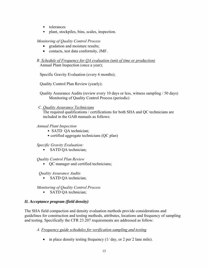
15
• tolerances • plant, stockpiles, bins, scales, inspection.
Monitoring of Quality Control Process
• gradation and moisture results; • contacts, test data conformity, JMF.
B. Schedule of Frequency for QA evaluation (unit of time or production)
Annual Plant Inspection (once a year); Specific Gravity Evaluation (every 6 months); Quality Control Plan Review (yearly); Quality Assurance Audits (review every 10 days or less, witness sampling / 50 days) Monitoring of Quality Control Process (periodic)
C. Quality Assurance Technicians
The required qualifications / certifications for both SHA and QC technicians are included in the GAB manuals as follows:
Annual Plant Inspection
• SATD QA technician; • certified aggregate technicians (QC plan)
Specific Gravity Evaluation:
• SATD QA technician; Quality Control Plan Review
• QC manager and certified technicians; Quality Assurance Audits
• SATD QA technician;
Monitoring of Quality Control Process • SATD QA technician;
II. Acceptance program (field density) The SHA field compaction and density evaluation methods provide considerations and guidelines for construction and testing methods, attributes, locations and frequency of sampling and testing. Specifically the CFR 23.207 requirements are addressed as follow:
A. Frequency guide schedules for verification sampling and testing
• in place density testing frequency (1/ day, or 2 per 2 lane mile).
16
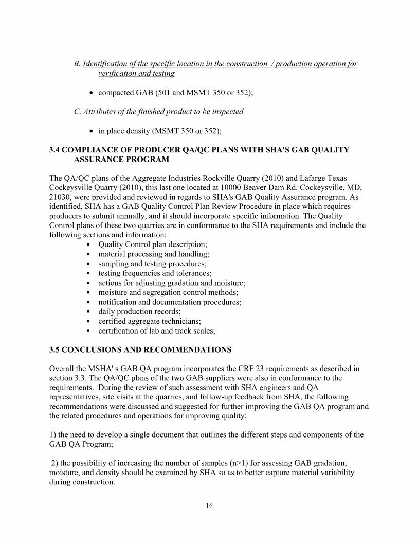
B. Identification of the specific location in the construction / production operation for verification and testing
• compacted GAB (501 and MSMT 350 or 352); C. Attributes of the finished product to be inspected
• in place density (MSMT 350 or 352); 3.4 COMPLIANCE OF PRODUCER QA/QC PLANS WITH SHA'S GAB QUALITY ASSURANCE PROGRAM The QA/QC plans of the Aggregate Industries Rockville Quarry (2010) and Lafarge Texas Cockeysville Quarry (2010), this last one located at 10000 Beaver Dam Rd. Cockeysville, MD, 21030, were provided and reviewed in regards to SHA's GAB Quality Assurance program. As identified, SHA has a GAB Quality Control Plan Review Procedure in place which requires producers to submit annually, and it should incorporate specific information. The Quality Control plans of these two quarries are in conformance to the SHA requirements and include the following sections and information:
• Quality Control plan description; • material processing and handling; • sampling and testing procedures; • testing frequencies and tolerances; • actions for adjusting gradation and moisture; • moisture and segregation control methods; • notification and documentation procedures; • daily production records; • certified aggregate technicians; • certification of lab and track scales;
3.5 CONCLUSIONS AND RECOMMENDATIONS Overall the MSHA' s GAB QA program incorporates the CRF 23 requirements as described in section 3.3. The QA/QC plans of the two GAB suppliers were also in conformance to the requirements. During the review of such assessment with SHA engineers and QA representatives, site visits at the quarries, and follow-up feedback from SHA, the following recommendations were discussed and suggested for further improving the GAB QA program and the related procedures and operations for improving quality: 1) the need to develop a single document that outlines the different steps and components of the GAB QA Program; 2) the possibility of increasing the number of samples (n>1) for assessing GAB gradation, moisture, and density should be examined by SHA so as to better capture material variability during construction.
17
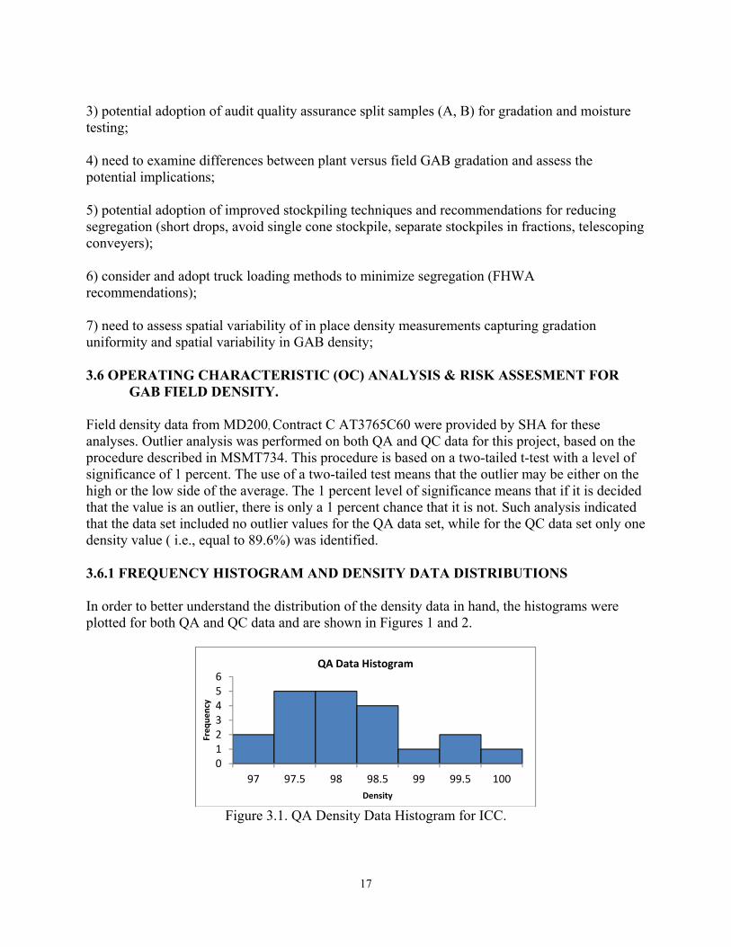
3) potential adoption of audit quality assurance split samples (A, B) for gradation and moisture testing; 4) need to examine differences between plant versus field GAB gradation and assess the potential implications; 5) potential adoption of improved stockpiling techniques and recommendations for reducing segregation (short drops, avoid single cone stockpile, separate stockpiles in fractions, telescoping conveyers); 6) consider and adopt truck loading methods to minimize segregation (FHWA recommendations); 7) need to assess spatial variability of in place density measurements capturing gradation uniformity and spatial variability in GAB density; 3.6 OPERATING CHARACTERISTIC (OC) ANALYSIS & RISK ASSESMENT FOR GAB FIELD DENSITY. Field density data from MD200, Contract C AT3765C60 were provided by SHA for these analyses. Outlier analysis was performed on both QA and QC data for this project, based on the procedure described in MSMT734. This procedure is based on a two-tailed t-test with a level of significance of 1 percent. The use of a two-tailed test means that the outlier may be either on the high or the low side of the average. The 1 percent level of significance means that if it is decided that the value is an outlier, there is only a 1 percent chance that it is not. Such analysis indicated that the data set included no outlier values for the QA data set, while for the QC data set only one density value ( i.e., equal to 89.6%) was identified. 3.6.1 FREQUENCY HISTOGRAM AND DENSITY DATA DISTRIBUTIONS In order to better understand the distribution of the density data in hand, the histograms were plotted for both QA and QC data and are shown in Figures 1 and 2.
Figure 3.1. QA Density Data Histogram for ICC.
0123456
97 97.5 98 98.5 99 99.5 100
Freq
uenc
y
Density
QA Data Histogram
18
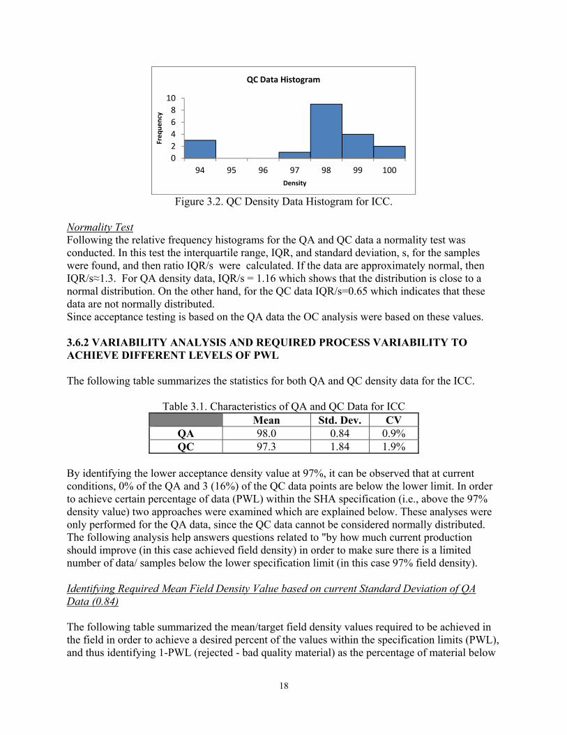
Figure 3.2. QC Density Data Histogram for ICC.
Normality Test Following the relative frequency histograms for the QA and QC data a normality test was conducted. In this test the interquartile range, IQR, and standard deviation, s, for the samples were found, and then ratio IQR/s were calculated. If the data are approximately normal, then IQR/s≈1.3. For QA density data, IQR/s = 1.16 which shows that the distribution is close to a normal distribution. On the other hand, for the QC data IQR/s=0.65 which indicates that these data are not normally distributed. Since acceptance testing is based on the QA data the OC analysis were based on these values. 3.6.2 VARIABILITY ANALYSIS AND REQUIRED PROCESS VARIABILITY TO ACHIEVE DIFFERENT LEVELS OF PWL The following table summarizes the statistics for both QA and QC density data for the ICC.
Table 3.1. Characteristics of QA and QC Data for ICC Mean Std. Dev. CV
QA 98.0 0.84 0.9% QC 97.3 1.84 1.9%
By identifying the lower acceptance density value at 97%, it can be observed that at current conditions, 0% of the QA and 3 (16%) of the QC data points are below the lower limit. In order to achieve certain percentage of data (PWL) within the SHA specification (i.e., above the 97% density value) two approaches were examined which are explained below. These analyses were only performed for the QA data, since the QC data cannot be considered normally distributed. The following analysis help answers questions related to "by how much current production should improve (in this case achieved field density) in order to make sure there is a limited number of data/ samples below the lower specification limit (in this case 97% field density). Identifying Required Mean Field Density Value based on current Standard Deviation of QA Data (0.84) The following table summarized the mean/target field density values required to be achieved in the field in order to achieve a desired percent of the values within the specification limits (PWL), and thus identifying 1-PWL (rejected - bad quality material) as the percentage of material below
02468
10
94 95 96 97 98 99 100Fr
eque
ncy
Density
QC Data Histogram
19
the target value (below 97%). These rejection levels (1-PWL) values are typically set at 5, 2.5 and 1 percent. The meaning of this analysis is that assuming that density production in the field cannot change (i..e, standard deviation remains the same for field density) what improvement in field density values (mean density value to be achieved in the field) will be needed in order to have only 1%, or 2.5%, or 5% of the data (rejected values) below the minimum target value of 97% density. Clearly this represents the potential risks of accepting or rejecting bad quality values. Table 3.2. Required Mean Field Density Value based on Current Standard Deviation of QA Data
(0.84) Mean/Target Value Lower Limit 1-PWL Z Std. Dev. QA data CV
98.3 97 5.0% 1.6045 0.84 0.9% 98.6 97 2.5% 1.96 0.84 0.9% 99.0 97 1.0% 2.325 0.84 0.8%
Identifying Required Reduction in Field Density Data Variability based on Field Mean Value of
QA data (98.0%) In this second case it is assumed that a contractor could do a better job for achieving a lower variability in field density. The following table summarized the standard deviations that need to be achieved in order to keep the percentage of rejected material (below 97%) at 5, 2.5 and 1 percent. Table 3.3. Required Reduction in Field Density Data Variability based on Field Mean Value of
QA data (98.0%) Mean/Target Value Lower Limit 1-PWL Z Desired Std. Dev. CV
98.0 97 5.0% 1.6045 0.62 0.6% 98.0 97 2.5% 1.96 0.51 0.5% 98.0 97 1.0% 2.325 0.43 0.4%
3.6.3 OPERATION CHARACTERISTICS (OC) ANALYSIS & RISKS ASSESSMENT The OC curves were developed using the procedure followed by Villiers et al. (2003) and using the standard error of the population in order to relate PWL and probability of acceptance. Based on the characteristics of all the QA data (average of 98.2% and standard deviation of 0.89), simulation analysis were run for various sample sizes (n) and using the 20 normally distributed QA data. Figure 3 shows four OC curves for different values of n.
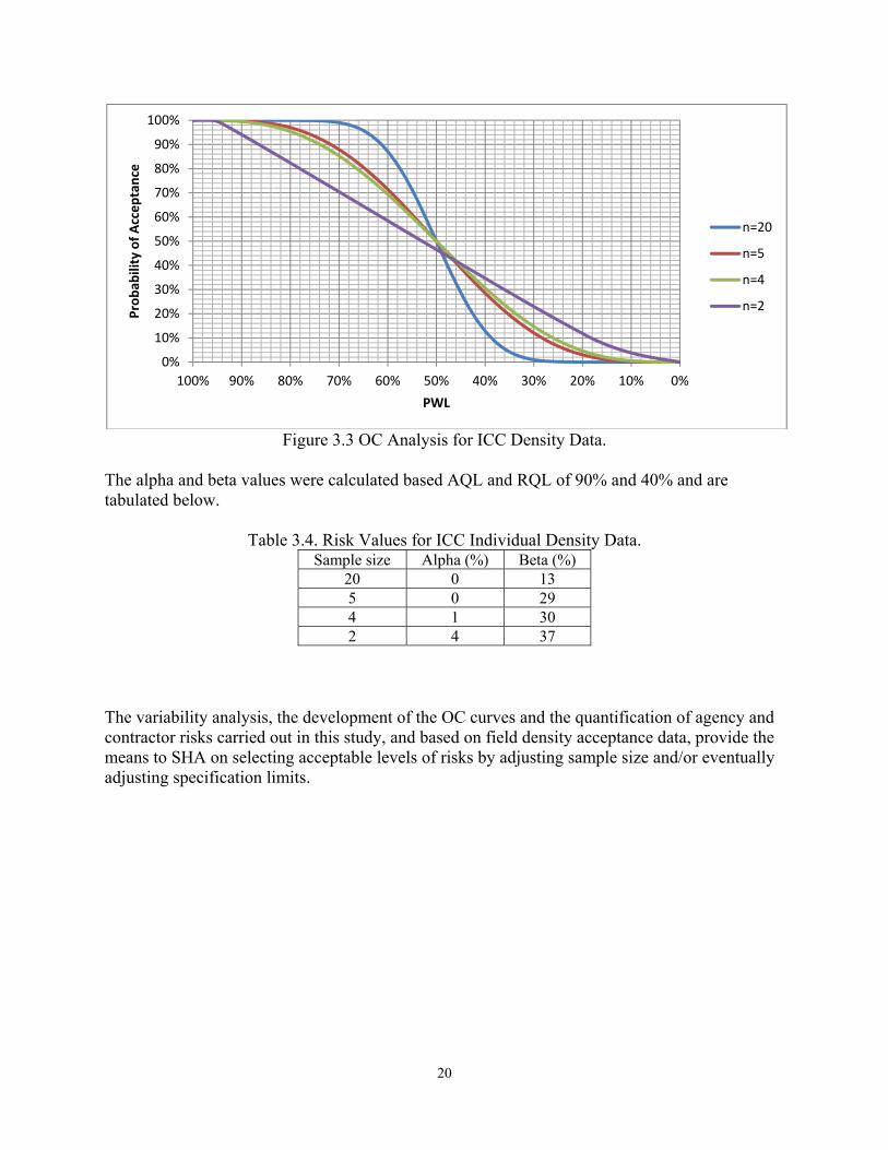
20
Figure 3.3 OC Analysis for ICC Density Data.
The alpha and beta values were calculated based AQL and RQL of 90% and 40% and are tabulated below.
Table 3.4. Risk Values for ICC Individual Density Data. Sample size Alpha (%) Beta (%)
20 0 13 5 0 29 4 1 30 2 4 37
The variability analysis, the development of the OC curves and the quantification of agency and contractor risks carried out in this study, and based on field density acceptance data, provide the means to SHA on selecting acceptable levels of risks by adjusting sample size and/or eventually adjusting specification limits.
0%
10%
20%
30%
40%
50%
60%
70%
80%
90%
100%
0%10%20%30%40%50%60%70%80%90%100%
Prob
abili
ty o
f Acc
epta
nce
PWL
n=20
n=5
n=4
n=2
21
CHAPTER 4 PRECAST CONCRETE QUALITY ASSURANCE PROGRAM (FOR DRAINAGE STRUCTURES) 4.1 INTRODUCTION The purpose of this review was to examine whether the Maryland State Highway Administration’s Precast Concrete Quality Assurance Inspection Manual for drainage structures (version 2009) addresses the CFR 23 federal policies and regulations (chapter 2). The purpose of the Precast Concrete Quality Assurance Inspection Manual is to identify the tasks and procedures necessary for conducting: a) the annual precast plant inspections, and b) the routine periodic quality assurance audits. This manual applies specifically to precast concrete drainage structure units such as, troughs, manholes, inlets and junction boxes, made from conventional or self-consolidating concrete. 4.2 PRECAST CONCRETE QUALITY ASSURANCE PROCESS FOR DRAINAGE
STRUCTURES As described in this manual, State Highway Administration is using three different types of Quality Assurance procedures: quality assurance audits of manufacturer quality control (35/ 50 plants); direct inspection of manufacturer quality control; and a hybrid system of both of the above. The Precast Concrete Quality Assurance Inspection Manual identifies the guidelines and tasks and procedures related to the quality assurance program followed by SHA, and it involves among other: a) annual precast plant inspections, and b) routine periodic quality assurance audits. Specifically, the following quality assurance steps are identified: i) Approved list of Manufacturers for precast drainage structures:
• Certified Plant by the National Precast Concrete Association (NPCA) ; • Annual Plant Inspection by SHA (or registered professional engineer)
Production plant’s qualifications- facilities inspection Annual QC Plan inspection
ii) Quality Assurance Audit of plant’s records and procedures (review of QC process &
personnel):
• Frequency (every ten production days, or, once per calendar month/ at least twice each year depending on plant production).
• Personnel (Senior SHA Quality Assurance Technician or Precast Engineer)
22
4.3 PRECAST CONCRETE QUALITY ASSURANCE INSPECTION MANUAL The manual incorporates several sections related to these quality assurance procedures and specifically it addresses the following: Quality Assurance Technicians (Section I) - Required certifications include SHA certified Concrete Plant Technicians and ACI Level I Field Certification to conduct Quality Assurance Audits. Frequency, (Section II) - Annual plant inspection (yearly); - Quality Assurance Audits (see above). Quality Assurance Audit, (Section III) - Resources and SHA personnel certifications (III.B); - Inspection activities, such as plant records, raw materials, testing/manufacturing (III C). - Inspection items (III E- F) including records audit of:
• plant certifications (NCPA, SHA); • QC plan; • daily production forms; • compressive strength reports (sample size, frequency, testing methods); • fresh concrete properties (slump, air, segregation, temperature); • mix designs; • Source of supply approvals (material certifications for forms, frames, steel,
cement etc.); - Lab inspection (III G), including QC testing equipment, QC technician certification; - Pre-pour inspection (III-H), formwork, liners; - Concrete placement (III-I), segregation, temperature, consolidation, placement (SCC); - Finished product and repairs (III.J to K), appearance dimensions; - Yard inspection (III- L); Annual Plant Inspection, (Section IV): - QC Plan review (IV.B), materials, procedures, test methods, mix designs, technician certifications; - Plant records audit;
- Facilities inspection (IV.C), physical plant tools, machinery, components and SHA QA Tech Inspection Checklists;
- Resources required (IV. E), SHA personnel certifications; Corrective Action & Suspension (V)
23
4.4 COMPLIANCE OF PRECAST CONCRETE QUALITY ASSURANCE PROGRAM WITH CFR 23 As identified in CRF 23 - 637.207 each STD's quality assurance program shall provide for: i) an acceptance program, and ii) independent assurance (IA) program. In the case of precast concrete drainage structures, the products are accepted based on: the Manufacturer’s certification that products meet specifications/ and requirements approved and verified by the following: (a) periodic quality assurance audits (b) annual plant inspections, (c) QC Plan requirements, review and approval (by SHA QA representative), (d) visual inspection and material certification verification upon jobsite delivery. Thus, while acceptance program is not considered by SHA on the characteristics and properties of these precast concrete drainage elements, the QA program is based on QA audits. Both (a) annual plant inspections/ approvals and (b) periodic quality assurance audits address the following characteristics/ requirements of CFR 23:
A. QA Evaluation of: Personnel & Equipment; Cover Sampling and Testing procedures,
& Equipment Both annual plant inspections and periodic plant audits include considerations and guidelines for sampling and testing personnel and the testing equipment. Details on sampling and testing procedures and testing equipment are identified. These issues are addressed in the following sections.
Quality Assurance Audit, (Section III)
- Inspection activities, such as plant records, raw materials, testing/manufacturing (III C). - Inspection items (III E- F) including records audit of:
• Plant certifications (NCPA, SHA); • QC plan; • Daily production forms; • Compressive strength reports (sample size, frequency, testing methods); • Fresh concrete properties (slump, air, segregation, temperature); • Mix designs; • Source of supply approvals (material certifications for forms, frames, steel,
cement etc.); - Lab inspection (III G), including QC testing equipment, QC technician certification (915.05); - Pre-pour inspection (III-H), formwork, liners; - Concrete placement (III-I), segregation, temperature, consolidation, placement (SCC); - finished product and repairs (III.J to K), appearance dimensions; - Yard inspection (III- L);
24
Annual Plant Inspection, (Section IV): - QC Plan review (IV.B), materials, procedures, test methods, mix designs, technician certifications (915); - Plant records audit; - Facilities inspection (IV.C), physical plant tools, machinery, components, and
SHA QA tech inspection checklists; - Resources required (IV. E), SHA personnel certifications.
B. Schedule of Frequency for QA audit (unit of time or production) The frequency of inspections for both annual plant inspections and periodic plant audits are identified in the precast concrete quality assurance manual.
II.A. Annual Plant Inspections are performed once every year no more than 30 calendar days beyond the date one year from the previous year’s annual inspection.
III.A. The frequency for performing Quality Assurance Audits is a random
schedule of every ten production days +5 days. In other words, audits are not less than 5 days apart and no more than 15 days apart, and, at low production plants must take place at least twice a year. Typically, for any given plant, this results in an audit about once a month.
C. Quality Assurance Technicians
The required qualifications / certifications for both annual and period inspections are identified in Section I of the manual as follows:
IA. State employees or consultant inspectors employed as Quality Assurance Technicians are required to be SHA certified Concrete Plant Technicians and must also hold ACI Level I Field Certification to conduct Quality Assurance Audits.
I.B. Annual Plant Inspections are required to be done by SHA certified state
employees only. 4.5 COMPLIANCE OF PRODUCER QA/QC MANUAL WITH SHA'S PRECAST CONCRETE QUALITY ASSURANCE INSPECTION MANUAL The QA/QC manuals of Hanson Pipe & Precast concrete plan for 2008, 2009 and 2010 were provided and reviewed in regards to SHA's Precast Concrete Quality Manual. Section III F.3 of the SHA Precast Concrete QA Manual identifies all the required documentation and testing information required for the producer's Quality Control Plan and QA/QC manual. The producer's QA/QC manuals that were examined are in compliance with such guidelines and address these requirements in the following sections and information:
- Quality Control plan - Source of Suppliers - Material testing procedures/ standards
25
- Concrete Mix Designs - Concrete Strength data (early break and 28 days cylinder strength data) - Other Concrete Test Results (unit weight, slump, air content) an - Materials' Certification (aggregates, cement, fly ash, admixtures, steel, etc..) - Certificates of Calibration (scales, loading, admixture measuring units, water meter, and
other testing equipment) 4.6 CONCLUSIONS AND RECOMMENDATIONS Overall the MSHA' s precast concrete QA program incorporates the CRF 23 requirements as described in Chapter 3. The QA/QC plans of the two suppliers were also in conformance to the requirements. During the review of such assessments with a) SHA engineers and QA representatives, b) site visits at the precast plants, and c) follow-up feedback from SHA, the following recommendations were discussed and suggested for i) further improving the precast concrete QA program and ii) the related procedures and operations for improving quality: 1) Potential consideration of quality assurance audits with split samples testing in the QA process or assessing mix design, aggregate gradation, strength, other critical parameters; It was reported by SHA representatives that CTD is currently evaluating a pilot program to procure and test comparison compressive strength specimens. Mix design is checked by compressive strength and plastic concrete tests – slump, air and temperature. Slump does not have a multi-operator precision statement so it is not possible to make operator to operator comparisons. Temperature and air eventually can be checked. SHA will need to issue the requisite equipment to CTD technicians as well as obtain additional equipment such as pencil vibrators, to permit testing of dry cast mixtures. SHA used to collect split of aggregates samples in the past. Split samples were found to not be an effective system of verification because the multi-operator precision statements were so broad that almost any gradation would compare favorably. SHA would like to collect parallel sets of representative samples to compare to the producers’ sample sets and the producers’ supplier. Unfortunately, none of the employees are certified to sample aggregates. The pilot program mentioned in the above-paragraph was not initiated by this study, but by an FHWA Audit performed several years ago, which produced a “Precast Improvement Plan”. Such plan was not available to the researchers of this study.
2) Inclusion of durability assessment of concrete mixtures and/or precast concrete elements in regards to freeze thaw and ASR measures, or adoption of warranties; as reported by SHA representatives, Freeze – Thaw durability is incorporated via the air entrainment specification by definition based on historical Corps of Engineers data. ASR resistance is incorporated via the ASR specification based on best practices and current industry standards. Freeze-Thaw processes are well understood and resistance mechanisms are designed into each mix where required. This is not to suggest that manufacturing defects cannot occur; however, there also do not appear to be any significant failures in this regard in any precast products of recent manufacture of which SHA is aware. ASR is much less well understood and new research in this area is developing almost daily. As better standards and practices become available SHA will be ready to adopt them.
26
3) Eventually introduce cement storage time limitations to avoid cement degradation, and further requirements and testing on aggregate and sand quality. To this regard the need for a pilot testing was suggested; Also, the possibility of specifying concrete mixtures was another area for potential inclusion into the precast concrete QA manual and procedures since some level of variability in concrete strength properties was observed over the years, and as shown in the variability analysis of section 4.7 based on the production data of the two precast concrete plants examined. However such suggestions was reviewed by SHA representatives and it was indicated that CTD has required precast batch plants to conform to all ready-mix plant requirements. This incorporates enhanced testing of materials and monitoring of silo temperatures of cementitious materials. “Shelf-life” is already part of AASHTO M-85 specification for cement. Thus, specifying concrete mixtures would represent return to prescriptive specifications which were abandoned in the 1968 Standard Specifications. The decision to require precast batch plants to conform to all ready-mix plant requirements was a decision that was made with CTD to further ensure material quality and consistency. 4) Potential adoption of an NDT method (perhaps GPR, ultrasonic pulse, or other type of approach) for assessing precast concrete drainage elements properties and quality. CTD recently procured a GPR device and is developing procedures to incorporate this technology into the QA Program. Training is pending opening in manufacturer representative’s schedule. 5) Stockpile management techniques for protect from elements and debris and promoting uniformity. 4.7 VARIABILITY ANALYSIS OF PRODUCERS' PRECAST CONCRETE QUALITY Two different plants producing precast concrete drainage elements were visited for observing production. Data from their QA/QC manuals were thus used to assess production quality and variability. Overall the testing results for the compressive strength, from both plants and for all mixtures, indicate that concrete variability is within acceptable values. The variability reported for the 28 day compressive strength for the Rinker Piper Precast plant (Table 4.1), was between 4% to 11% depending on the mixture, while for the Hanson Pipe and Precast Concrete plant only the 28 day strength values for their SCC mix were included in their QA/QC manuals, providing a variability of 4% (Table 4.5). Earlier age compressive strength data indicated higher variability values but these are less relevant than the target 28 day strength values. Also the quality control chart analyses indicate that there is an expected randomness in concrete production, and in all cases the process is “in control,” according to the "theory of runs" as outlines in FHWA Statistical Quality Control of Highway Construction Volume 1, chapter 16, and reported in sections 4.7.1 and 4.7.2. The detailed analyses are presented next. 4.7.1 RINKER PIPE PRECAST CONCRETE PLANT The 2010 DriCast Quality Control Plan manual for the Rinker Pipe precast concrete plant included production data for 6 different mixes. At each date the average strength for day 7 and day 28 was reported. The following table summarizes the characteristics for each mix.
27
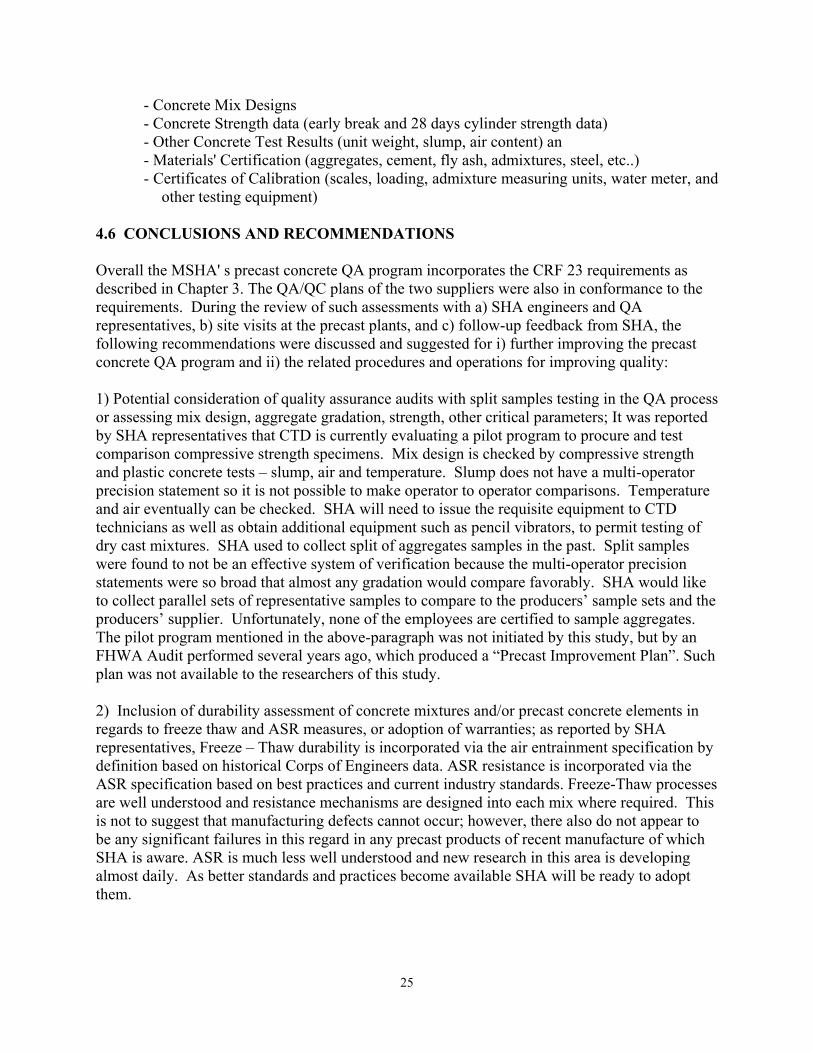
Table 4.1. Concrete Mix Characteristics for Rinker Pipe Plant Mix Age Count Average S 2S 3S CV
4000CY 7 30 4225 324 648 972 8% 28 26 5105 334 668 1002 7%
4000 MM
7 28 4026 300 600 900 7% 28 28 4779 349 698 1047 7%
4000 MM Big
Bore
7 27 4183 435 870 1305 10%
28 24 5198 540 1080 1620 10%
4000 WC 7 30 4981 546 1092 1638 11% 28 27 5765 625 1250 1875 11%
6000 CY 7 28 5233 412 824 1236 8% 28 23 6882 306 612 918 4%
6000 MM
7 30 4866 395 790 1185 8% 28 27 6382 447 894 1341 7%
CONTROL CHARTS
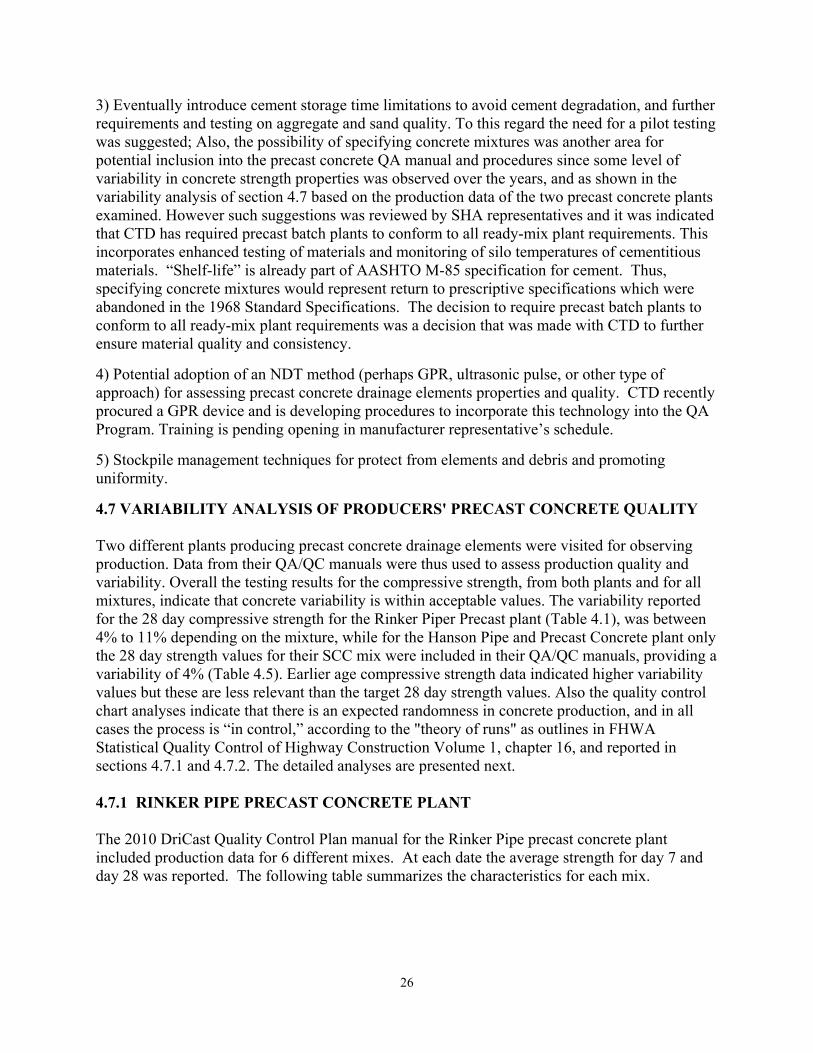
1) Mix 4000 CY For mix 4000 CY a total of 56 data points were reported (30 at day 7, and 26 at day 28). Based on the reported values, the following controls charts were developed.
Figure 4.1. Control Chart for Mix 4000 CY, 7 Day Strength Data
3000
3500
4000
4500
5000
5500
10/7/09 10/25/09 11/12/09 11/30/09 12/18/09 1/5/10 1/23/10
Stre
ngth
(psi
)
4000 CY Day 7Value Average ±S ±2S ±3S

28
Figure 4.2. Control Chart for Mix 4000 CY, 28 Day Strength Data.
As illustrated in the preceding two figures, all the data fall within three standard deviation of their average. In terms of variability and randomness of the production process the "theory of runs" may be used to these data (FHWA Statistical Quality Control of Highway Construction Volume 1 - ch16). According to these guidelines the process may be considered “out of control” when:
- Whenever, in 11 successive points on the control chart, at least 10 are on the same side of the central line.
- Whenever, in 14 successive points on the control chart, at least 12 are on the same side of the central line.
- Whenever, in 17 successive points on the control chart, at least 14 are on the same side of the central line.
- Whenever, in 20 successive points on the control chart, at least 16 are on the same side of the central line.
From these data sets it appears that the concrete production in this plant does not fall under the “out of control” category.
2) Mix 4000 MM For mix 4000 CY total of 56 data points were reported (28 at day 7, and 28 at day 28). Based on the reported values, the following controls charts were developed. As illustrated in the following two figures, all the data fall within three standard deviation of their average, and for this mixture as well it appears that the concrete production in this plant does not fall under the “out of control” category.
4000
4500
5000
5500
6000
6500
10/7/09 10/22/09 11/6/09 11/21/09 12/6/09 12/21/09 1/5/10
Stre
ngth
(psi
)4000 CY Day 28
Value Average ±S ±2S ±3S

29
Figure 4.3. Control Chart for Mix 4000 MM, 7 Day Strength Data.
Figure 4.4. Control Chart for Mix 4000 MM, Day 28 Strength Data.
3000
3500
4000
4500
5000
9/3/09 9/17/09 10/1/0910/15/0910/29/0911/12/0911/26/0912/10/0912/24/09 1/7/10
Stre
ngth
(psi
)4000 MM Day 7
Value Average ±S ±2S ±3S
3500
4000
4500
5000
5500
6000
9/3/09 9/19/09 10/5/09 10/21/09 11/6/09 11/22/09 12/8/09 12/24/09 1/9/10
Stre
ngth
(psi
)
4000 MM Day 28Value Average ±S ±2S ±3S
30
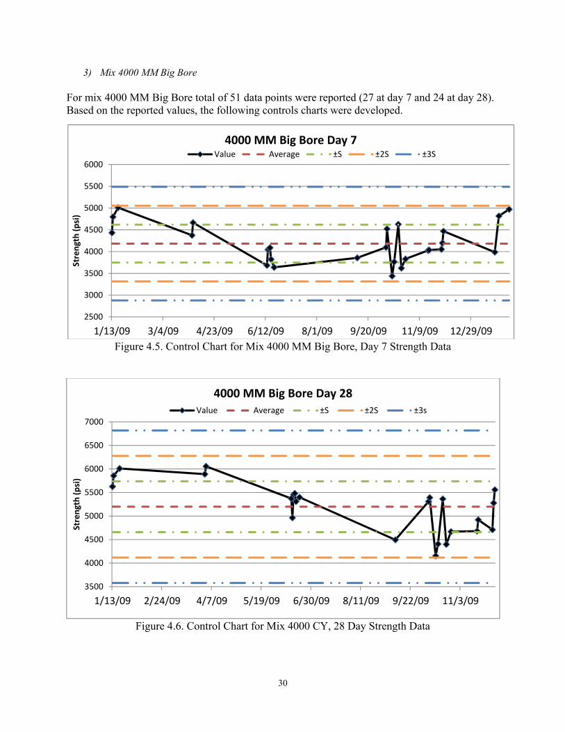
3) Mix 4000 MM Big Bore For mix 4000 MM Big Bore total of 51 data points were reported (27 at day 7 and 24 at day 28). Based on the reported values, the following controls charts were developed.
Figure 4.5. Control Chart for Mix 4000 MM Big Bore, Day 7 Strength Data
Figure 4.6. Control Chart for Mix 4000 CY, 28 Day Strength Data
2500
3000
3500
4000
4500
5000
5500
6000
1/13/09 3/4/09 4/23/09 6/12/09 8/1/09 9/20/09 11/9/09 12/29/09
Stre
ngth
(psi
)
4000 MM Big Bore Day 7Value Average ±S ±2S ±3S
3500
4000
4500
5000
5500
6000
6500
7000
1/13/09 2/24/09 4/7/09 5/19/09 6/30/09 8/11/09 9/22/09 11/3/09
Stre
ngth
(psi
)
4000 MM Big Bore Day 28Value Average ±S ±2S ±3s
31
As illustrated in the preceding two figures, all the data fall within two standard deviation of their average, and for this mixture as well it appears that the concrete production in this plant does not fall under the “out of control” category.
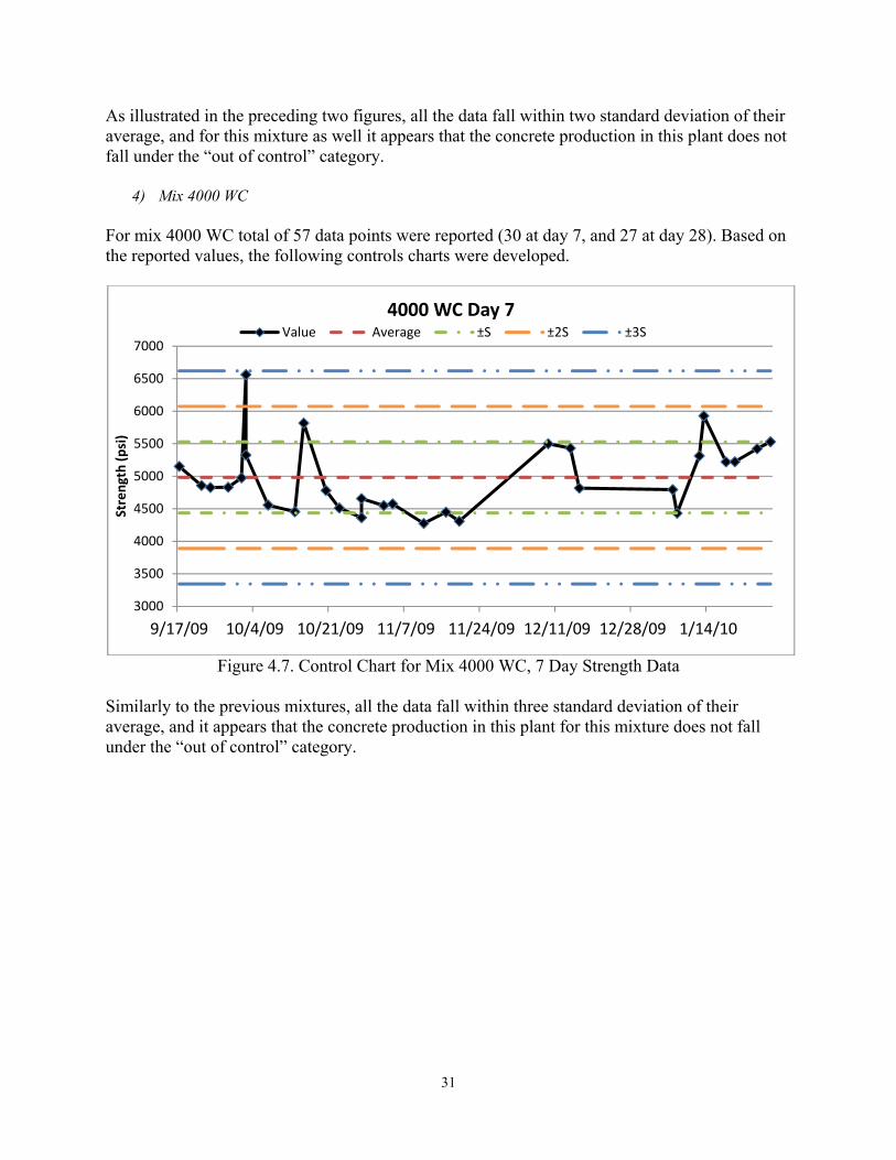
4) Mix 4000 WC For mix 4000 WC total of 57 data points were reported (30 at day 7, and 27 at day 28). Based on the reported values, the following controls charts were developed.
Figure 4.7. Control Chart for Mix 4000 WC, 7 Day Strength Data
Similarly to the previous mixtures, all the data fall within three standard deviation of their average, and it appears that the concrete production in this plant for this mixture does not fall under the “out of control” category.
3000
3500
4000
4500
5000
5500
6000
6500
7000
9/17/09 10/4/09 10/21/09 11/7/09 11/24/09 12/11/09 12/28/09 1/14/10
Stre
ngth
(psi
)
4000 WC Day 7Value Average ±S ±2S ±3S
32
Figure 4.8. Control Chart for Mix 4000 WC, 28 Day Strength Data
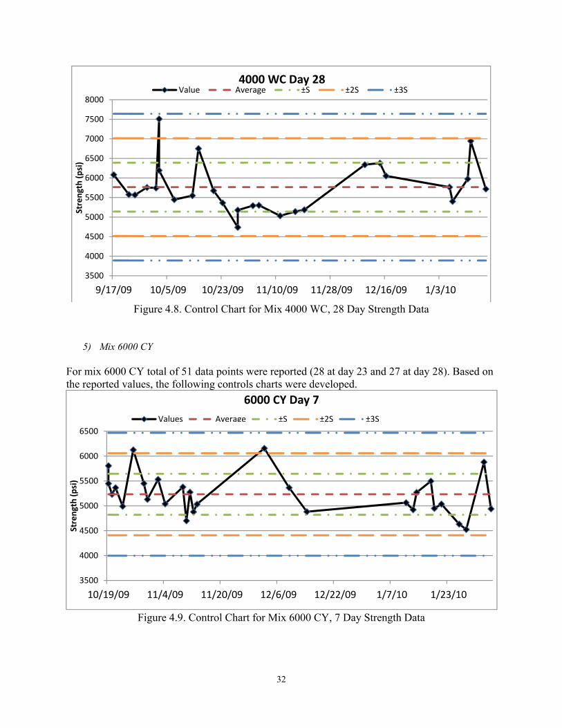
5) Mix 6000 CY For mix 6000 CY total of 51 data points were reported (28 at day 23 and 27 at day 28). Based on the reported values, the following controls charts were developed.
Figure 4.9. Control Chart for Mix 6000 CY, 7 Day Strength Data
3500
4000
4500
5000
5500
6000
6500
7000
7500
8000
9/17/09 10/5/09 10/23/09 11/10/09 11/28/09 12/16/09 1/3/10
Stre
ngth
(psi
)4000 WC Day 28
Value Average ±S ±2S ±3S
3500
4000
4500
5000
5500
6000
6500
10/19/09 11/4/09 11/20/09 12/6/09 12/22/09 1/7/10 1/23/10
Stre
ngth
(psi
)
6000 CY Day 7Values Average ±S ±2S ±3S
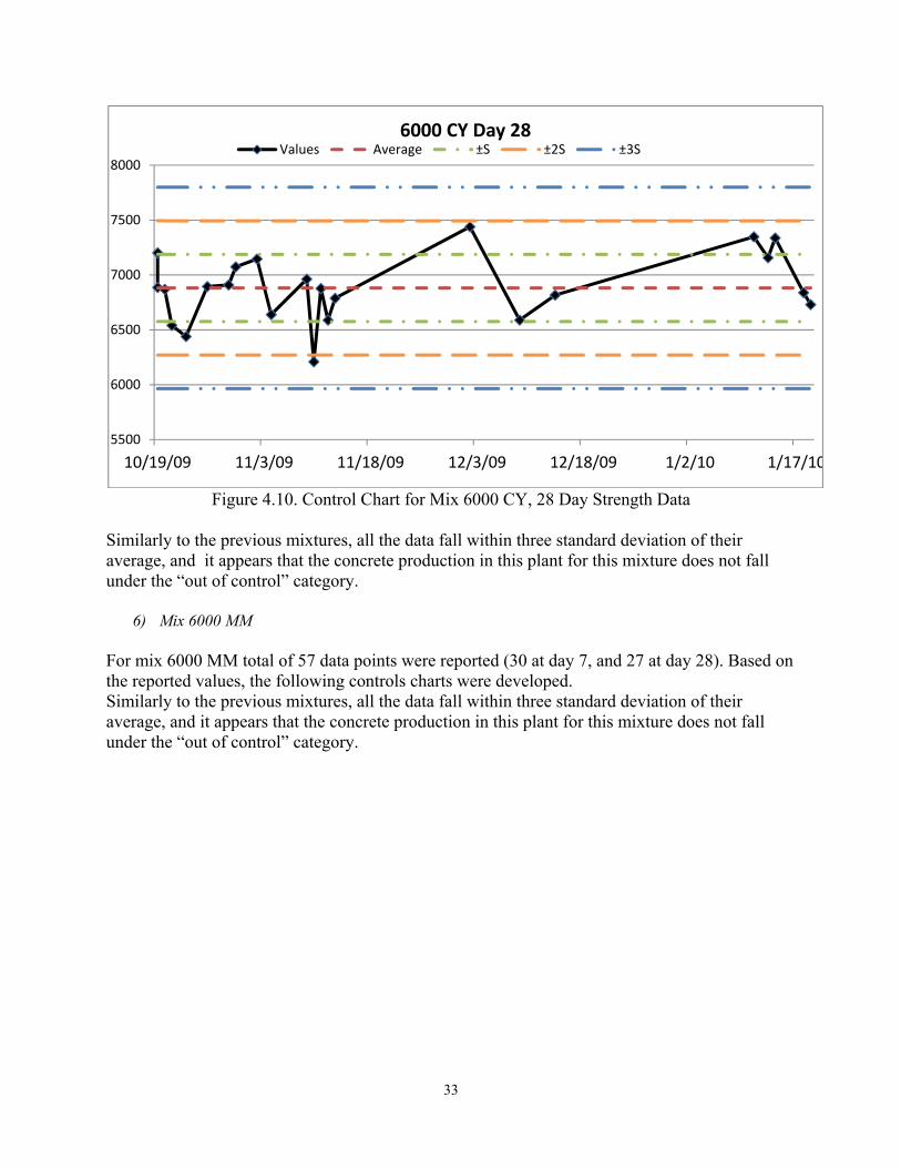
33
Figure 4.10. Control Chart for Mix 6000 CY, 28 Day Strength Data
Similarly to the previous mixtures, all the data fall within three standard deviation of their average, and it appears that the concrete production in this plant for this mixture does not fall under the “out of control” category.
6) Mix 6000 MM For mix 6000 MM total of 57 data points were reported (30 at day 7, and 27 at day 28). Based on the reported values, the following controls charts were developed. Similarly to the previous mixtures, all the data fall within three standard deviation of their average, and it appears that the concrete production in this plant for this mixture does not fall under the “out of control” category.
5500
6000
6500
7000
7500
8000
10/19/09 11/3/09 11/18/09 12/3/09 12/18/09 1/2/10 1/17/10
6000 CY Day 28Values Average ±S ±2S ±3S

34
Figure 4.11. Control Chart for Mix 6000 MM, 7 Day Strength Data
Figure 4.12. Control Chart for Mix 6000 MM, 28 Day Strength Data
3500
4000
4500
5000
5500
6000
6500
8/3/09 8/25/09 9/16/09 10/8/09 10/30/09 11/21/09 12/13/09 1/4/10 1/26/10
Stre
ngth
(psi
)6000 MM Day 7
Values Average ±S ±2S ±3S
5000
5500
6000
6500
7000
7500
8000
8/3/09 8/22/09 9/10/09 9/29/09 10/18/09 11/6/09 11/25/09 12/14/09 1/2/10
(str
engt
h (p
si)
6000 MM Day 28Values Average ±S ±2S ±3S

35
NORMALITY TEST In order to identify the probability distributions for these data, the 7 and 28 day strength values were used. Two descriptive methods were used to check for normality.
1- Construct a relative frequency histogram display for data. If the data are approximately normal, the shape of the graph will be similar to the normal curve.
2- Find the interquartile range, IQR, and standard deviation, s, for the sample, then calculate the ratio IQR/s. If the data are approximately normal, then IQR/s≈1.3
The following are the relative frequency histograms for the mixtures from this plant.
Figure 4.13. Relative Frequency Histogram (n=30) for Mix 4000 CY, 7 Day Strength Data
Figure 4.14. Relative Frequency Histogram (n=26) for Mix 4000 CY, 28 Day Strength Data
012345678
3850 4050 4250 4450 4650 4850
Freq
uenc
y
Bin
4000 CY Day 7
02468
10
4620 4870 5120 5370 5620 5870
Freq
uenc
y
Bin
4000 CY Day 28
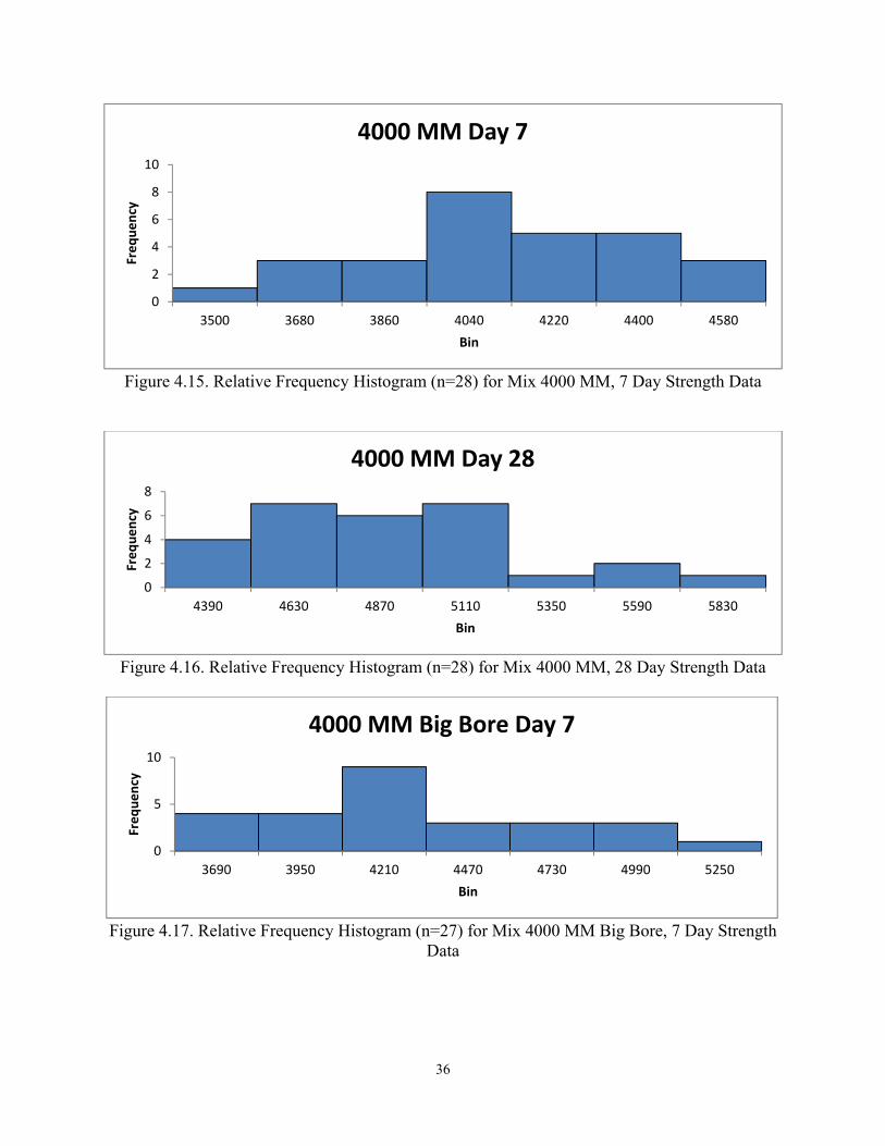
36
Figure 4.15. Relative Frequency Histogram (n=28) for Mix 4000 MM, 7 Day Strength Data
Figure 4.16. Relative Frequency Histogram (n=28) for Mix 4000 MM, 28 Day Strength Data
Figure 4.17. Relative Frequency Histogram (n=27) for Mix 4000 MM Big Bore, 7 Day Strength
Data
0
2
4
6
8
10
3500 3680 3860 4040 4220 4400 4580
Freq
uenc
y
Bin
4000 MM Day 7
0
2
4
6
8
4390 4630 4870 5110 5350 5590 5830
Freq
uenc
y
Bin
4000 MM Day 28
0
5
10
3690 3950 4210 4470 4730 4990 5250
Freq
uenc
y
Bin
4000 MM Big Bore Day 7
37
Figure 4.18. Relative Frequency Histogram (n=24) for Mix 4000 MM Big Bore, 28 Day Strength
Data
Figure 4.19. Relative Frequency Histogram (n=30) for Mix 4000 WC, 7 Day Strength Data
Figure 4.20. Relative Frequency Histogram (n=27) for Mix 4000 WC, 28 Day Strength Data
0
2
4
6
8
4470 4790 5110 5430 5750 6070
Freq
uenc
y
Bin
4000 MM Big Bore Day 28
02468
1012
4580 4960 5340 5720 6100 6480 6860
Freq
uenc
y
Bin
4000 WC Day 7
0
5
10
15
5160 5620 6080 6540 7000 7460 7920
Freq
uenc
y
Bin
4000 WC Day 28
38
Figure 4.21. Relative Frequency Histogram (n=28) for Mix 6000 CY, 7 Day Strength Data
Figure 4.22. Relative Frequency Histogram (n=23) for Mix 6000 CY, 28 Day Strength Data
Figure 4.23. Relative Frequency Histogram (n=30) for Mix 6000 MM, 7 Day Strength Data
0
5
10
4770 5040 5310 5580 5850 6120 6390
Freq
uenc
y
Bin
6000 CY Day 7
0
2
4
6
8
10
6400 6600 6800 7000 7200 7400 7600
Freq
uenc
y
Bin
6000 CY Day 28
0
2
4
6
8
10
4350 4600 4850 5100 5350 5600 5850
Freq
uenc
y
Bin
6000 MM Day 7
39
Figure 4.24. Relative Frequency Histogram (n=27) for Mix 6000 MM, 28 Day Strength Data
The following table summarizes the IQR/s for all of the above distributions. The highlighted data sets can be assumed to be normal and thus normal distribution can be used for these population of data for estimate PWL values within the specification limits (percent of material within the specification limits based on the current production characteristics).
Table 4.2. Normality Test Results for Rinker Pipe Concrete Mixtures
Mix Day 7 Day 28 4000 CY 1.7 1.2 4000 MM 1.3 1.2
4000 MM Big Bore 1.5 1.5 4000 WC 1.4 1.2 6000 CY 1.2 1.4 6000 MM 1.4 1.0
4.7.2 HANSON PIPE & PRECAST CONCRETE PLANT The three year QA/QC Manuals (2008, 2009 and 2010) of the Hanson Pipe & Precast concrete plant included a series of concrete production data. Individual and average values were reported by year, concrete age and mix type. These data were used to i) examine the quality and variability of the production process, and ii) identify the probability distribution characteristics of the strength data in order to develop simulation analysis for evaluating risks. Some of these results are included herein as part of the 3rd quarter progress report. CONTROL CHARTS (INDIVIDUAL VALUES)
- YEAR 2006 PRODUCTION
For year 2006 a total of 36 records were available for two different concrete mixes, Wet Cast Straight Portland (WC1) and Wet Cast 20% Fly-ash (WC2). Even thought this group of data, reported in Table 1, was rather limited in sample data points and replicates, the central tendency and variance provide an assessment of the variability of the concrete production process. Overall, the coefficient of variation for both mixtures is at a level of approximately 10%, perhaps
0
5
10
15
5500 5900 6300 6700 7100 7500 7900
Freq
uenc
y
Bin
6000 MM Day 28
40
indentifying the potential for further improvement in reducing variability in concrete production, and/or reducing testing variability.
Table 4.3. Statistical Characteristics of WC1 Year 2006 WC1 (Individual Values)
Age Count Average S 2S 3S CV 1 4 4089 410 820 1230 10% 3 4 4994 629 1257 1886 13% 7 4 6038 1094 2188 3283 18% 11 0 - - - - - 14 2 6645 - - - - 21 2 7222 - - - - 28 2 7282 - - - -
Table 4.4. Statistical Characteristics of WC2
Year 2006 WC2 (Individual Values) Age Count Average S 2S 3S CV
1 4 2735 82 164 246 3% 3 4 3680 377 753 1130 10% 7 4 4367 136 271 407 3% 11 0 - - - - - 14 2 5312 - - - - 21 2 5929 - - - - 28 2 6346 - - - -
- YEAR 2008 Production
For year 2008 a total of 82 data points were reported for mixture SCC MIX#1. The following table summarizes the average, standard deviation and coefficient of variation at different concrete ages.
Table 4.5. Statistical Characteristics of SCC MIX#1 Year 2008 SCC MIX#1 (Individual Values)
Age Count Average S 2S 3S CV Mix 1 2 1729 - - - - SCC MIX#1 3 0 - - - - - SCC MIX#1 7 46 6195 682 1364 2046 11% SCC MIX#1 11 0 - - - - - SCC MIX#1 14 2 6446 - - - - SCC MIX#1 21 2 7322 - - - - SCC MIX#1 28 30 7718 335 669 1004 4% SCC MIX#1
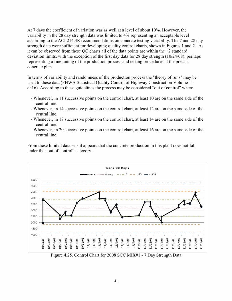
41
At 7 days the coefficient of variation was as well at a level of about 10%. However, the variability in the 28 day strength data was limited to 4% representing an acceptable level according to the ACI 214.3R recommendations on concrete testing variability. The 7 and 28 day strength data were sufficient for developing quality control charts, shown in Figures 1 and 2. As it can be observed from these QC charts all of the data points are within the ±2 standard deviation limits, with the exception of the first day data for 28 day strength (10/24/08), perhaps representing a fine tuning of the production process and testing procedures at the precast concrete plan. In terms of variability and randomness of the production process the "theory of runs" may be used to these data (FHWA Statistical Quality Control of Highway Construction Volume 1 - ch16). According to these guidelines the process may be considered “out of control” when:
- Whenever, in 11 successive points on the control chart, at least 10 are on the same side of the central line.
- Whenever, in 14 successive points on the control chart, at least 12 are on the same side of the central line.
- Whenever, in 17 successive points on the control chart, at least 14 are on the same side of the central line.
- Whenever, in 20 successive points on the control chart, at least 16 are on the same side of the central line.
From these limited data sets it appears that the concrete production in this plant does not fall under the “out of control” category.
Figure 4.25. Control Chart for 2008 SCC MIX#1 - 7 Day Strength Data
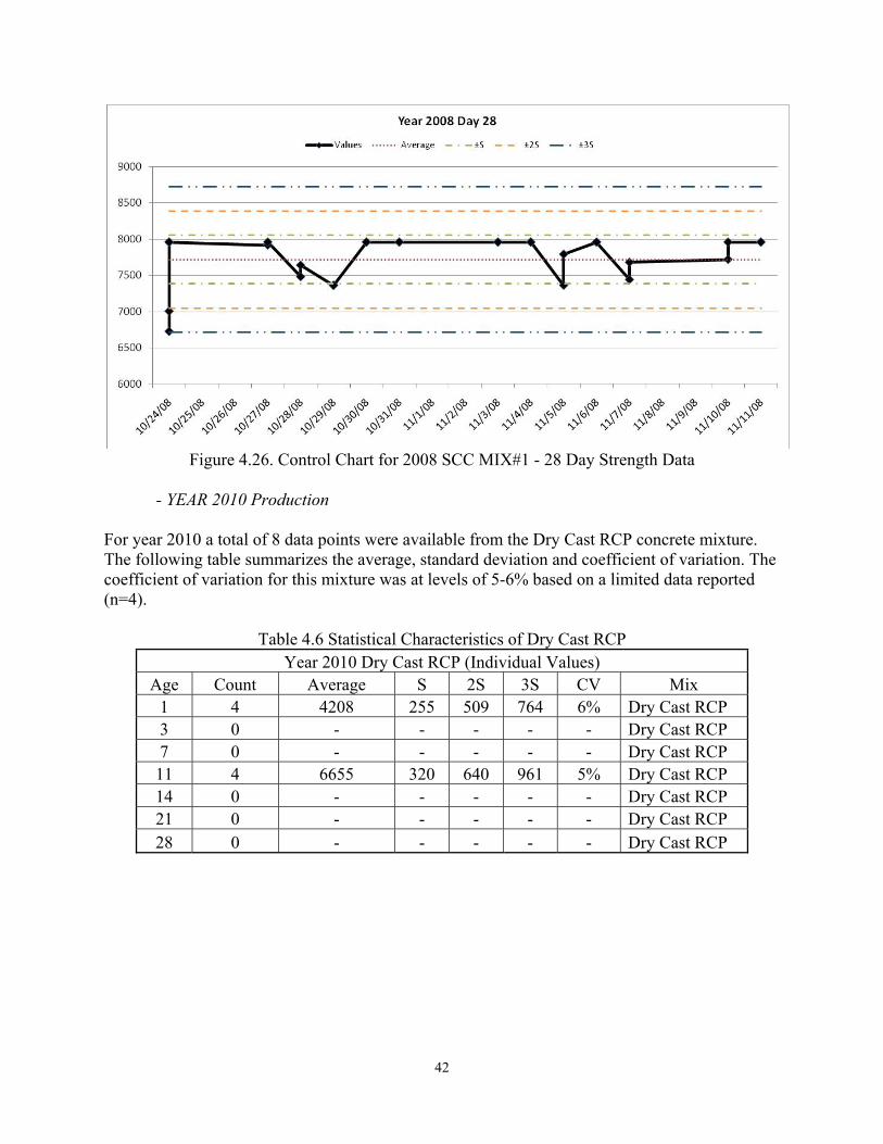
42
Figure 4.26. Control Chart for 2008 SCC MIX#1 - 28 Day Strength Data
- YEAR 2010 Production For year 2010 a total of 8 data points were available from the Dry Cast RCP concrete mixture. The following table summarizes the average, standard deviation and coefficient of variation. The coefficient of variation for this mixture was at levels of 5-6% based on a limited data reported (n=4).
Table 4.6 Statistical Characteristics of Dry Cast RCP Year 2010 Dry Cast RCP (Individual Values)
Age Count Average S 2S 3S CV Mix 1 4 4208 255 509 764 6% Dry Cast RCP 3 0 - - - - - Dry Cast RCP 7 0 - - - - - Dry Cast RCP 11 4 6655 320 640 961 5% Dry Cast RCP 14 0 - - - - - Dry Cast RCP 21 0 - - - - - Dry Cast RCP 28 0 - - - - - Dry Cast RCP
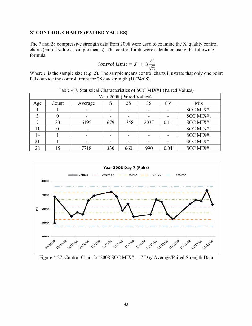
43
X' CONTROL CHARTS (PAIRED VALUES) The 7 and 28 compressive strength data from 2008 were used to examine the X' quality control charts (paired values - sample means). The control limits were calculated using the following formula: = ′ ± 3 ′√
Where n is the sample size (e.g. 2). The sample means control charts illustrate that only one point falls outside the control limits for 28 day strength (10/24/08).
Table 4.7. Statistical Characteristics of SCC MIX#1 (Paired Values) Year 2008 (Paired Values)
Age Count Average S 2S 3S CV Mix 1 1 - - - - - SCC MIX#1 3 0 - - - - - SCC MIX#1 7 23 6195 679 1358 2037 0.11 SCC MIX#1 11 0 - - - - - SCC MIX#1 14 1 - - - - - SCC MIX#1 21 1 - - - - - SCC MIX#1 28 15 7718 330 660 990 0.04 SCC MIX#1
Figure 4.27. Control Chart for 2008 SCC MIX#1 - 7 Day Average/Paired Strength Data
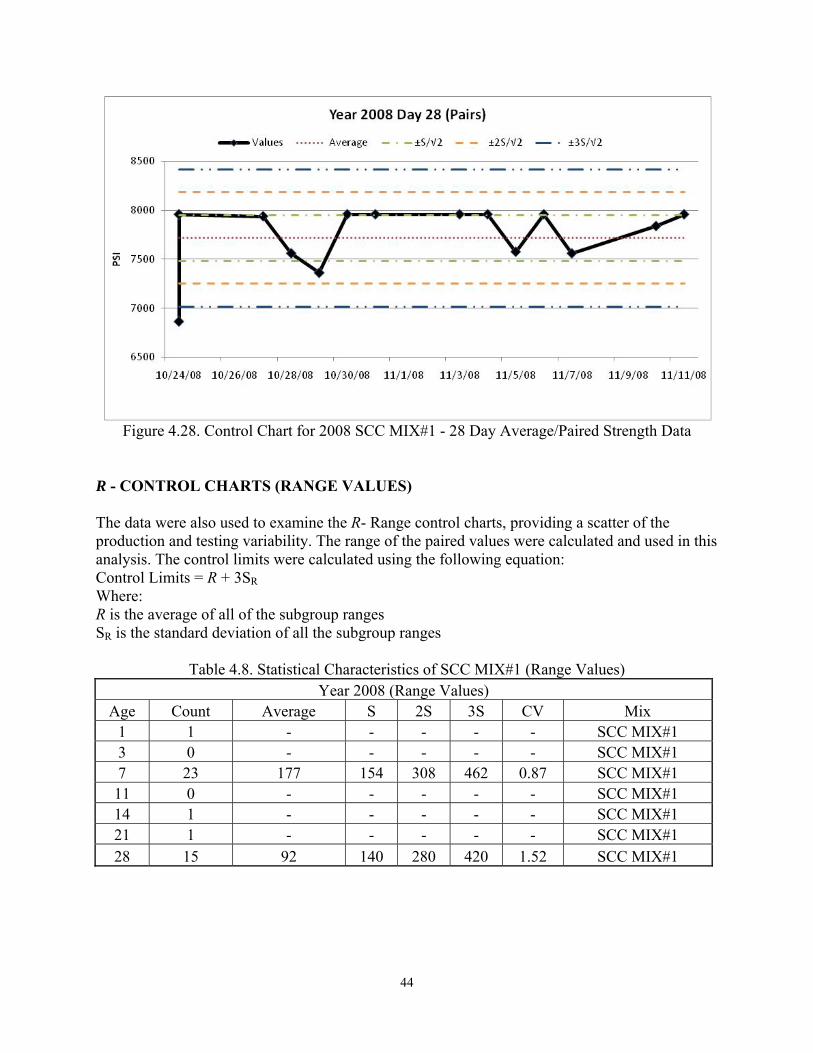
44
Figure 4.28. Control Chart for 2008 SCC MIX#1 - 28 Day Average/Paired Strength Data
R - CONTROL CHARTS (RANGE VALUES) The data were also used to examine the R- Range control charts, providing a scatter of the production and testing variability. The range of the paired values were calculated and used in this analysis. The control limits were calculated using the following equation: Control Limits = R + 3SR Where: R is the average of all of the subgroup ranges SR is the standard deviation of all the subgroup ranges
Table 4.8. Statistical Characteristics of SCC MIX#1 (Range Values) Year 2008 (Range Values)
Age Count Average S 2S 3S CV Mix 1 1 - - - - - SCC MIX#1 3 0 - - - - - SCC MIX#1 7 23 177 154 308 462 0.87 SCC MIX#1 11 0 - - - - - SCC MIX#1 14 1 - - - - - SCC MIX#1 21 1 - - - - - SCC MIX#1 28 15 92 140 280 420 1.52 SCC MIX#1
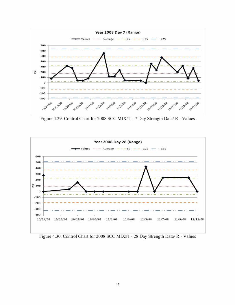
45
Figure 4.29. Control Chart for 2008 SCC MIX#1 - 7 Day Strength Data/ R - Values
Figure 4.30. Control Chart for 2008 SCC MIX#1 - 28 Day Strength Data/ R - Values
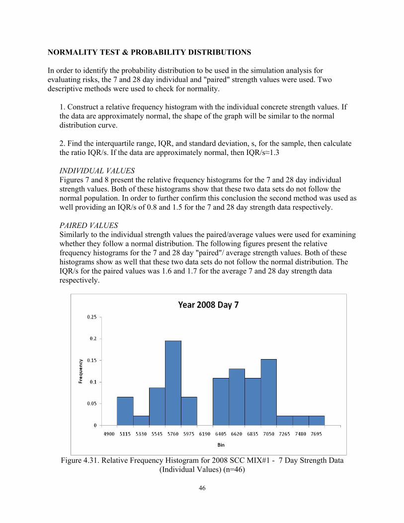
46
NORMALITY TEST & PROBABILITY DISTRIBUTIONS In order to identify the probability distribution to be used in the simulation analysis for evaluating risks, the 7 and 28 day individual and "paired" strength values were used. Two descriptive methods were used to check for normality.
1. Construct a relative frequency histogram with the individual concrete strength values. If the data are approximately normal, the shape of the graph will be similar to the normal distribution curve.
2. Find the interquartile range, IQR, and standard deviation, s, for the sample, then calculate the ratio IQR/s. If the data are approximately normal, then IQR/s≈1.3 INDIVIDUAL VALUES Figures 7 and 8 present the relative frequency histograms for the 7 and 28 day individual strength values. Both of these histograms show that these two data sets do not follow the normal population. In order to further confirm this conclusion the second method was used as well providing an IQR/s of 0.8 and 1.5 for the 7 and 28 day strength data respectively. PAIRED VALUES Similarly to the individual strength values the paired/average values were used for examining whether they follow a normal distribution. The following figures present the relative frequency histograms for the 7 and 28 day "paired"/ average strength values. Both of these histograms show as well that these two data sets do not follow the normal distribution. The IQR/s for the paired values was 1.6 and 1.7 for the average 7 and 28 day strength data respectively.
Figure 4.31. Relative Frequency Histogram for 2008 SCC MIX#1 - 7 Day Strength Data
(Individual Values) (n=46)

47
Figure 4.32. Relative Frequency Histogram for 2008 SCC MIX#1 - 28 Day Strength Data
(Individual Values) (n=30)
Figure 4.33. Relative Frequency Histogram for 2008 SCC MIX#1 - 7 Day Paired/Average
Strength Values (n=23)
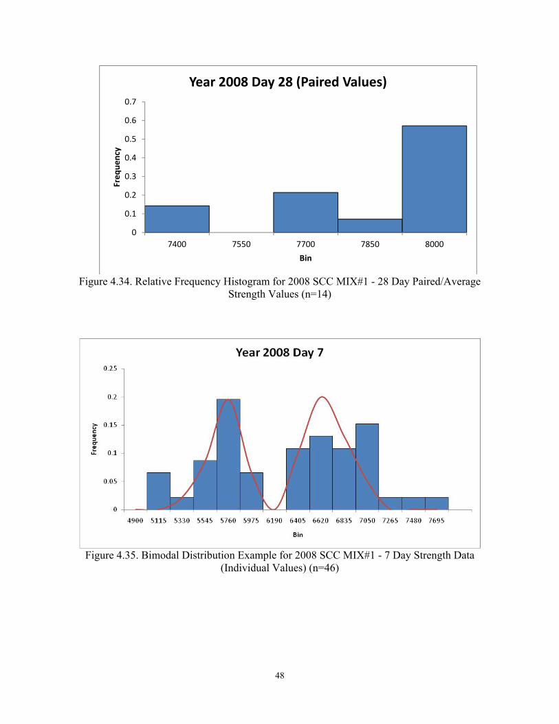
48
Figure 4.34. Relative Frequency Histogram for 2008 SCC MIX#1 - 28 Day Paired/Average
Strength Values (n=14)
Figure 4.35. Bimodal Distribution Example for 2008 SCC MIX#1 - 7 Day Strength Data
(Individual Values) (n=46)
0
0.1
0.2
0.3
0.4
0.5
0.6
0.7
7400 7550 7700 7850 8000
Freq
uenc
y
Bin
Year 2008 Day 28 (Paired Values)
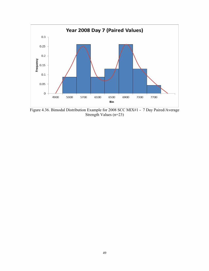
49
Figure 4.36. Bimodal Distribution Example for 2008 SCC MIX#1 - 7 Day Paired/Average
Strength Values (n=23)
50
CHAPTER 5. STRUCTURAL STEEL QUALITY ASSURANCE PROGRAM 5.1 INTRODUCTION The policies and regulations of the Code of Federal Regulations (CFR) title 23, described in chapter 2, were used in examining compliance of Maryland State Highway Administration’s Structural Steel Quality Assurance program in relation to these requirements. Several documents describing different components of Maryland State Highway Administration’s Structural Steel Quality Assurance procedures were provided and considered in this review. These included:
1- Policy for Identifying Fabrication Facilities for Annual Facility Audit 2- Fabricated Structural Steel Plant Audit Checklist 3- Fabricated Structural Steel Quality Control Plan Review 4- NCR Quality Discrepancy Report 5- Assignment of Agency Inspectors 6- Welder Audit Procedure 7- Applied Inorganic Zinc Rich Primer (Paint Form) 8- Policy for Sampling, Testing and Accepting Anchoring Materials for Lighting and
Signing Materials 9- Policy for Inspecting and Approving Structural Steel Items for Shipment to Field/Project
Locations 10- Fabrication Facility Weekly Status Report 11- Policy for Submitting Final Reports on Structural Steel 12- FHWA Standard 104A Recommended Practice for Preparation of A QC Plan
The purpose of each document is as follows:
1- Policy for Identifying Fabrication Facilities for Annual Facility Audit: this policy identifies the method for insuring proper auditing (documents and frequency) of the fabrication facilities that are producing materials for SHA.
2- Fabricated Structural Steel Plant Audit Forms: objective of this document and forms is to identify all necessary audit components for fabricated structural steel plant audit.
3- Fabricated Structural Steel QUALITY CONTROL PLAN Review: identifies the required components / sections to be included and reviewed in a QC plan for fabricated structural steel. Includes ALL STEPS of Fabricated Structural Steel Plant Audit Forms and is based on the recommendations and procedures of the 1994 FHWA Standard 104A "Recommended Practice for the Preparation of Quality Control Plan."
4- NCR Quality Discrepancy Report: to report non-conformance and identify corrective action by QC representative.
5- Assignment of Agency Inspectors: procedure for assigning agency inspectors, duties, work description and payments.
51
6- Welder Audit Procedure: to assess that the proper welding procedures and equipment/methods are used by welders working on bridge projects.
7- Applied Inorganic Zinc Rich Primer (Paint Form): provides certification for paint primer meeting AASHTO M-300 specification.
8- Policy for Sampling, Testing and Accepting Anchoring Materials for Lighting and Signing Materials: procedure for sampling, testing and accepting anchoring materials used in foundations of lighting and signing materials
9- Policy for Inspecting and Approving Structural Steel Items for Shipment to Field/Project Locations: procedure for proper marking of materials shipped at job site.
10- Fabrication Facility Weekly Status Report: to monitor the production/delivery of structural steel and coating type used for the SHA contracts.
11- Policy for Submitting Final Reports on Structural Steel: documentation and reports of inspected structural steel items.
12- FHWA Standard 104A Recommended Practice for Preparation of a QC Plan: identifying the recommended components of a QC Plan for Structural Steel fabricators.
5.2 QUALITY ASSURANCE PROCESS FOR STRUCTURAL STEEL. The SHA Structural Steel Quality Assurance program is based on a combination of fabrication plant inspections, QC plan requirements and review, periodic audits on materials and production methods, material certifications, and personnel qualifications/certifications. In summary the following elements are incorporated in this SHA QA program:
i) annual plant inspections/audits for structural steel; ii) QC plan review; iii) on-site inspections using agency inspectors; iv) certifications/audits/ verification of materials and methods; v) reporting
The key components of this QA process are presented next. A. Identification of Fabrication Facilities for Annual Audit
Pertinent document: Policy for Identifying Fabrication Facilities for Annual Facility Audit: this policy identifies the method for insuring proper auditing and oversight on the fabrication facilities that are producing materials for SHA. The policy includes i) a review of key information and documents, and ii) identifies the schedule for facility audit based on the following: i) review of:
• contact info • QC Manual
52
• Audit Report ii) schedule:
• Starting FY 2010 every 6 months determine facilities that produce for SHA • Audit must be done within 18 months • If 90 days till the 18 month cycle, conduct an audit • Audit can be conducted by team members, consultant forces or both • When not audited with 18 months Team Leader can decide to postpone the audit
based on third party information: other state agencies, review of QC file, inspection agency or inspectors that have current knowledge of facility
B. Fabricated Structural Steel Plant Audit
It includes the review of all the requirements listed in FHWA’s Standard 104A QC Plan guidelines such as the following:
1. General Management (Scope of QC Plan)
• QC Plan 2. Policy (Statement for Quality)
• Policy for conformance to contract documents and specifications; 3. Fabricator Organization & QC
• positions & functions, qualifications & (CWI, State) certifications, QC vs production activities/operations;
4. Certifications (plant & Personnel) • AISC Plant certification; • QC and NDT personnel certifications;
5. Governing Specifications & Standards • SHA specs and material manual, AASHTO and ASTM specs, ANSI/AWS,
welding codes, drawings, ASNT-NDT, other. 6. Procedures - Material
• raw material handling, grade & quality verification, marking, compliance to ASTM-A6, verification of subcontracted material, material test reports vs specification requirements, proper identification, storage and inventory of materials.
7. Procedures - Consumables • electrodes, wire and flux: purchased, marked and stored based on specs. • paint properly identified and stored; • certifications of all consumables in relation to contract requirements
8. Procedures - Welding • Welders Certification System (CWI-Certified Welding inspector), testing and
records, welders identification and certification system; • workmanship conformance to contracts and specs • welding procedures, heat curving procedures, heat control and blocking
procedures properly posted and followed. 9. NDT
• personnel qualifications and certification (State, ASNT - American Society of Nondestructive Testing, internal)
53
• compliance of NDT resources to project requirements 10. Inspection Procedures - Raw Material
• personnel familiarity with ASTM A-6, inspection forms, verification and frequency by QC personnel, un-acceptable material disregarded.
11. Inspection Procedures - Material Preparation • inspection logs, verification and frequency by QC personnel, acceptance criteria,
un-acceptable cuts marked & segregated, verification of repairs. 12. Inspection Procedures - Fitting Material
• inspection logs, verification and frequency by QC personnel, sign-off procedure prior to welding, marking of un-acceptable conditions.
13. Inspection Procedures - Welding • AWS certification of inspection personnel; welding procedures; required sizes of
fillet welds; verification, frequency & documentation by QC personnel; verification, frequency & documentation of welding consumables by QC personnel; Per-Heat verification, frequency & documentation by QC personnel; Visual acceptance; marking of un-acceptable welds, repair & re-inspection.
13. Heat Cambering, Curing & Straightening • procedure for curving/straightening acceptance; equipment; verification and
frequency by QC personnel; handling and documentation of un-acceptable conditions.
14. Shop Assembly of Main Members
• Dimensional accuracy; accuracy of camber, sweep, bearing fit; accuracy and conditions of holes; flange tilt, twists, buckles; segregation of un-acceptable conditions. repair follow up.
15. Blast Cleaning & Shop Painting
• surface cleaning ( solvent wipe) prior to blast; check of blast surface; evaluation and frequency of recycled blast medium for contaminants; temperature, humidity and dew point verification and frequency; review of paint quality and certification.
16. Storage • Blocking verification; damage inspection.
17. Shipping
• Storage/handling damage inspection; Blocking of load for shipment; final QC inspection.
C. Quality Control Plan Review & Discrepancy Reports.
Pertinent documents: Fabricated Structural Steel QC Plan Review: identifies the required components / sections to be included and reviewed in a QC plan for fabricated structural steel. Includes all requirements included in the Fabricated Structural Steel Plant Audit Form, and refers to the recommendations and procedures of the 1994 FHWA Standard 104A "Recommended Practice for the Preparation of Quality Control Plan:"

54
• Standard 104A Recommended Practice for the Preparation of a QC Plan Summary: 104A.1 Scope of QC Plan 104A.3 Statement of support for Quality 104A.4 Fabricator Organization 104A.5 QC Section Organization 104A.6 QC Personnel 104A.7 Fabrication Plant Certification 104A.8 Governing Specifications 104A.9 Shop Drawings 104A.10 Mill Orders and Purchase of Materials 104A.11 Certified Mill Test Data and Certifications 104A.12 Welding Procedures 104A.13 Welder Consumable 104A.14 Welder Qualification 104A.15 NDT 104A.16 Inspection Procedure for Incoming Raw Material 104A.17 Inspection Procedure for Preparation of Material 104A.18 Inspection Procedures for Fitting 104A.19 Welding Inspection Procedures 104A.20 Heat Camber, Curving and Straightening 104A.21 Shop Assembly of Main Members 104A.22 Stud Welding Operations 104A.23 Strength Bolt Installation 104A.24 Blast Cleaning and Shop Painting 104A.25 Loading and Shipping
D. On site Inspections using Agency Inspectors
Pertinent documents: Assignment of Agency Inspectors: procedure for assigning agency inspectors, duties, work description and payments.
E. Audit of Methods / Procedures & Certification of Materials This is conducted, a) in the annual Plant audits, b) by the agency inspectors, and c) included in the acceptance/ approval reports. Pertinent documents:
Fabricated Structural Steel Plant Audit Checklist (addressed previously) Fabricated Structural Steel Quality Control Plan Review (addressed previously) Welder Audit Procedure
Procedure performed under AWS D1.5 Bridge Welding Code. It includes: i) audit performance frequency - minimum once a week per fabricating facility; location - random welding station for each audit; monitor - welding procedure; personnel - welder qualifications, welder to be selected randomly
55
ii) reports Welder Audit Form Non conformance report
Applied Inorganic Zinc Rich Primer (Paint Form) Bridge paint type certification related to AASHTO M-300 specification for inorganic zinc coat. Policy for Sampling, Testing and Accepting Anchoring Materials for Lighting and Signing Materials The procedure includes: a) the sampling and destructive testing by OMT for compliance and specifications of bar stock at the point of manufacture, b) final inspection at point of manufacture or supplier and b) submittal of test reports. The procedure refers to the OMT Frequency guide for sampling and testing of anchor bolts, nuts/ washer material, and thus relates to SHA Metals Standard 909.06 (grade and galvanized requirements); Other requirements include: i) inspectors daily audits; ii) drawings; iii) the Mill Heat reports (Heat Log, High Strength Fasteners including Rotational Capacity Tests 909.07, and Charpy V Notch Testing if upgrading any materials from the mill); iv) QC inspection reports; v) coating reports (Dry Film Thickness Reports , Paint Certifications, Galvanizing Certifications) related to SHA 912 Coating systems for Structural Steel; Non Conformance Reports (NCR); Shipping Reports/Bill of Lading. Policy for Inspecting and Approving Structural Steel Items for Shipment to Field/Project Locations Policy for assuring that materials meet all of the contract and construction standards through 1B inspections on a source of supply. (Note 1B:Material inspected and/or tested by authorized SHA Lab personnel or authorized agency prior to delivery to the job site. Material accompanied by a Bill of Lading or Shipping Ticket stamped by an SHA - OMT Representative or authorized agency).
G. Production Monitoring and Reporting
Pertinent documents: Fabrication Facility Weekly Status Report Monitoring of the production/delivery of structural steel and coating type used for SHA contracts. Policy for Submitting Final Reports on Structural Steel Identifies required documentation and reports of inspected structural steel items by OMT and assigned agencies (Quality Assurance Reports for fabrication shop/plants maintained during fabrication; final report completed within two weeks of the final shipment for a specific state contract). In-house inspector representing SHA shall insure that the following is included:
• Inspection Authorization & daily inspections log; • Drawings;
56
• Mill Test Reports including, a) Heat Log, b) High Strength Fasteners including Rotational Capacity Tests, c) Charpy V Notch Testing if upgrading any materials form the mill;
• QC inspection reports & welding acceptance reports and repairs. • Coating reports (Dry Film Thickness, Paint and Galvanizing Certifications) • Non Conformance reports (NCR) and corrective actions. • Shipping Reports/Bill of Lading.
5.3 SHA QA PROCESS & FHWA STANDARD 104A ON RECOMMENDED QC PLAN PRACTICE This SHA quality assurance process is based on several of the FHWA guidelines, methods and procedures identified in the 1994 Standard 104A "Recommended Practice for the Preparation of Quality Control Plan," and thus it covers the following sections/ requirements:
- QC organization and functions; - Production & QC personnel certifications; - Fabrication Plant certifications; - QC Plan & Review; - Raw material requirements, certifications and inspection (mill certifications, paint,
consumables); - Production procedures, testing methods, and frequency of testing for assessing compliance
of quality and production; (welding, heat cambering, curving, straightening, shop assembly, blast cleaning, painting, storage, shipping);
- Agency inspectors & duties; - Certifications & required documentation, including loading and shipping.
5.4 SHA QA PROCESS & CFR 23.637 As identified in CRF 23 - 637.207 each STD's quality assurance program shall provide for: i) an acceptance program, ii) independent assurance (IA) program, iii) materials certification. In the case of structural steel the SHA quality assurance program is based on material certification through (a) annual plant inspections, and (b) periodic quality assurance audits. Both (a) annual plant inspections and (b) periodic quality assurance audits address the following key elements:
Inspections & Attributes Plant inspections, raw materials certifications, production methods
audits/inspections.
Location & Frequency of Inspections Plant and Production Inspections: raw materials, consumables, procedures. QC Plan QC Plan requirements and QC Plan review. Evaluation/ Certification of QC & Production Personnel
57
QC personnel, production personnel, agency inspectors (as per contract requirements).
The QC plan and fabrication plant inspections do include considerations and
guidelines for the required QC and production personnel qualifications and certifications. For specific production steps, such as the welder audits, the SHA audit methods identify the sampling and verification procedures for observing compliance of the work performed in relation to acceptable standards of practice.
Certification/ Requirements for Raw Materials, Production Methods and/or
Equipment, Testing Methods The QC plan, the fabrication plant inspections, and periodic audits do include
considerations and guidelines on materials sampling and testing procedures, and testing equipment .
Corrective Action (Repairs& Re-inspection)
The NCR Quality Discrepancy Report is included in several steps of the production process to report non-conformance and identify corrective action by QC representative.
Certification of Final Product / Materials
Identified at several stages during inspection and, audits and production and part of the "Policy for Submitting Final Reports on Structural Steel"
5.5 COMPLIANCE OF PRODUCER QA/QC MANUAL WITH SHA'S QUALITY CONTROL PLAN GUIDELINES QC manuals from two fabricators were provided. The first one was related to a structural steel fabricator, while the second one was from a manufacturer of Reticuline & Straight Roadway Frames & Grates. These QC manuals were reviewed in regards to the SHA's Quality Control Plan Guidelines. The required components / sections are included in the "Fabricated Structural Steel QC Plan Review form and follow the requirements and recommendations of the 1994 FHWA Standard 104A "Recommended Practice for the Preparation of Quality Control Plan:" The Quality Control manual of the structural steel fabricator was overall in conformance to the SHA requirements even though it often included general description of compliance with SHA requirements, and included the following sections and information:
104A.1 Scope of QC Plan 104A.3 Statement of support for Quality 104A.4 Fabricator Organization 104A.5 QC Section Organization 104A.6 QC Personnel 104A.7 Fabrication Plant Certification 104A.8 Governing Specifications 104A.9 Shop Drawings 104A.10 Mill Orders and Purchase of Materials (not available)
58
104A.11 Certified Mill Test Data and Certifications (not available) 104A.12 Welding Procedures 104A.13 Welder Consumable 104A.14 Welder Qualification 104A.15 NDT 104A.16 Inspection Procedure for Incoming Raw Material 104A.17 Inspection Procedure for Preparation of Material 104A.18 Inspection Procedures for Fitting 104A.19 Welding Inspection Procedures 104A.20 Heat Camber, Curving and Straightening 104A.21 Shop Assembly of Main Members 104A.22 Stud Welding Operations 104A.23 Strength Bolt Installation 104A.24 Blast Cleaning and Shop Painting 104A.25 Loading and Shipping
The second Quality Control manual was from a "Reticuline & Straight Roadway Frames & Grates" manufacturer, and thus several sections of the QC requirements were not included. Some pages of this manual were also missing (pg. 18-20). Specifically the following components were present in this QC manual:
104A.1 Scope of QC Plan 104A.3 Statement of support for Quality 104A.4 Fabricator Organization 104A.5 QC Section Organization 104A.6 QC Personnel 104A.7 Fabrication Plant Certification 104A.8 Governing Specifications 104A.9 Shop Drawings 104A.10 Mill Orders and Purchase of Materials (not available) 104A.11 Certified Mill Test Data and Certifications (not available) 104A.12 Welding Procedures 104A.13 Welder Consumable 104A.14 Welder Qualification 104A.15 NDT (visual inspection) 104A.16 Inspection Procedure for Incoming Raw Material 104A.17 Inspection Procedure for Preparation of Material 104A.18 Inspection Procedures for Fitting 104A.19 Welding Inspection Procedures 104A.20 Heat Camber, Curving and Straightening 104A.21 Shop Assembly of Main Members 104A.22 Stud Welding Operations 104A.23 Strength Bolt Installation (not available) 104A.24 Blast Cleaning and Shop Painting 104A.25 Loading and Shipping
59
5.6 CONCLUSIONS AND RECOMMENDATIONS Overall the MSHA' s QA program for Structural Steel incorporates the CRF 23 requirements as described in chapter 2 and documented in section 5.4. Furthermore, as mentioned in section 5.3, this SHA quality assurance process is based on FHWA guidelines, methods and procedures identified in the 1994 Standard 104A "Recommended Practice for the Preparation of Quality Control Plan." The QA/QC plans of two structural steel suppliers were also in conformance to the major requirements. During the review of such assessment with SHA engineers the following recommendations were discussed and suggested for further improving the QA program and the related procedures and operations for improving quality:
1) The need to develop a single QA Manual that outlines the different steps and components of the QA Process for Structural Steel (similar to the Rebar Inspection Program outlying each components and referring to the applicable ASTM/AASHTO and SHA standards); 2) Potential inclusion of independent samples for verification testing at SHA labs or independent laboratories; 3) The structural steel QA program includes on-site inspections through agency inspectors. While the procedure for assigning agency inspectors, duties, work description and payments is included into the QA program, there are no guidelines on the minimum qualifications and certifications. Further feedback from SHA engineers indicated that such requirements are eventually included into the related SHA NW 1-3-11 contract issued for each specific project;
4) Potential review of historical records during production and repairs. The QA Program and QCP requirements and applicable specifications include specific methods of inspection and corrective actions. The producers keep track of the historical records related to the production data and repairs (including type of repairs and frequency). As discussed with SHA engineers, such analysis could provide inside on production variability analysis (per plant and between plants), and eventually assess impact of deviations on performance.
60
CHAPTER 6. REBAR CERTIFICATION PROGRAM 6.1 INTRODUCTION The purpose of this review was to examine whether the Maryland State Highway Administration’s Rebar Certification Program addresses the key components of CFR 23 federal policies and regulations (described in chapter 2). The documents pertinent to the various components of Maryland State Highway Administration’s Rebar Certification Program were:
1- Rebar Certification Program; 2- Rebar Plant Approval Procedure Checklist.
The purpose of each document is as follows:
1- Rebar Certification Program: this document identifies the different components of the certification program.
2- Rebar Plant Approval Procedure Checklist: objective of this document is to verify that all audit and QC documents related to plant approval for rebars have been reviewed and are in place.
6.2 REBAR CERTIFICATION PROGRAM. The SHA Rebar Certification program is based on a combination a) QC Plan (QCP) requirements and review, b) material certifications, and c) a rebar plant audit/ inspection to review whether the QCP elements and other handling and critical records are in place. In summary the following steps are incorporated in this SHA certification program for approval: a) Quality Control Plan (QCP) review; b) On-site audit of fabrication facility to assure QCP in place and functioning; The "Rebar Plant Certification Program" document incorporates among other the following guidelines: 1a) Submission, review and approval of supplier's / manufacturer's Quality Control Plan (QCP). This QCP should include the following components:
- organizational structure of the company; - method of heat identification monitoring for bars during storage and fabrication; - reviewing method of mill test reports and conformance to ASTM specs; - review of company's record retention system; - method of touch-up procedure.
1b) On-site audit on-site audit of fabrication facility to assure QCP in place and functioning; 2) Rebar Plant Certification Approval Review Cost Estimate;

61
3) SHA Deformed Reinforcing Steel Specifications; This includes: Section 421 Reinforcing Steel Identifying use of uncoated and epoxy coated reinforcing steel Section 908 Reinforcement Steel 908.00 Certification of each heat of steel as per TC-1.03 908.01 Deformed Reinforcement - Grade 60 deformed bars per ASTM A 615 or A 706. - epoxy coated when specified; - epoxy powder as per section 917.02 (fusion bonded epoxy powder coatings) Section TC-1.03 - certification that material meets applicable specs and includes required tests - certification made in USA or except as per section 165 - ISTEA 1982/1991, etc. Section 917 Miscellaneous Protective Coatings 917.02 Fusion Bonded Epoxy Powder Coatings ( AASHTO M284 - ASTM 775) - one coat, heat curable, thermosetting powdered coating - electrostatically applied; - color identification for reinforcement steel; - for coated reinforcement before fabrication any hairline cracks should be patched with SHA prequalified epoxy coating list. 917.02.01 Touch Up System - two part epoxy system and color matched with epoxy coating .
- same source/manufacturer as epoxy powder. - patching fully cured one hour after application at 35 F ambient.
917.02.02 Certification (as per TC-1.03). 4) ASTM 615 Deformed and Plain Carbon-Steel Bars for Concrete Reinforcement
- materials, chemical composition, designation numbers, dimensions, deformation requirements, weights, tensile properties, bending test, finish, required tests and reports, inspection, rejection, marking, packaging.
5) Plant Review Checklist It refers to the Requirements of Quality Control Plan
a) Description of the organizational structure b) Description of heat ID during manufacturing, fabrication, coating and storage and
shipping c) Certification conformance review d) Record retention system e) Touch-up system procedure
6) In-Plant Reinforcing Steel Fabricator/ Supplier Quality Review Audit Checklist
62
Identifies the inspection of Quality Control Process components during fabricator/supplier plant audit review.
1. Storage and handling procedures: - storage conditions;
2. Roller protection method: - protection of contact areas during rolling and shearing process;
3. Method of transportation: - proper shipping;
4. Touch - up procedures and material storage - touch-up material quality and storage, touch-up procedure;
5. Material inspection pre and post fabrication (cutting/bending): - labeling for shipment, damaged rebars, and mill tags;
6. Certification review process: procedures and personnel;
7. Certification retention and traceability: - review records & assess traceability by MDOT.
7) Additional Documentation - Sample Qualified Acceptance Letter - Qualified Fabricators and Suppliers list.
- Work Flow and Filing for review process - Example of Audit Report
6.3 SHA QA INSPECTION PROCESS & CFR 23.637 As identified in CRF 23 - 637.207 each STD's quality assurance program shall provide for: i) an acceptance program, ii) independent assurance (IA) program, iii) materials certification. The SHA quality assurance approach for Rebars is primarily a certification program and is based on a combination of: i) QC Plan (QCP) requirements and review, ii) material certifications, and iii) a rebar plant audit/ inspection to review whether the QCP elements and other handling and critical records are in place. As such, the Rebar Certification Program address the following key elements:
Certification/ Requirements for Materials, Production Methods and/or Equipment,
Testing Methods The Rebar Certification Program relies on material certifications meeting
requirements identified in SHA standards 908, 917, and certification TC-1.03. Further reference on production procedures, material requirements, testing, inspection, and marking is included in ASTM 615 and AASHTO M 284/ ASTM 775)
Inspection /Audit & Frequency of Inspection This certification program primarily includes a one-time plant inspection for
verifying the implementation of the QCP. No further inspections are considered, or mentioned in the QA procedures, as production of rebars goes on. Similarly,
63
raw materials certifications and production methods are not audited as production goes on.
QC Plan & Review QC Plan requirements and a QCP review and plant implementation are included
as part of this process. Evaluation/ Certification of QC & Production Personnel No specific requirements/ qualifications are considered for the QC personnel,
production personnel, and agency inspectors. Corrective Action (Repairs& Re-inspection)
The ASTM and SHA standards included in this certification program, along with the QCP requirements includes specific methods of inspection and corrective actions and the identification of touch-up procedures.
6.4 COMPLIANCE OF PRODUCER QA/QC MANUAL WITH SHA'S QUALITY CONTROL PLAN GUIDELINES QC manuals from two rebar fabricators/suppliers were provided. These QC manuals were reviewed in regards to the SHA's Quality Control Plan Guidelines. These quality control manuals were in conformance to the SHA requirements and included the following sections/ information:
• organizational structure of the company; • method of heat identification monitoring for bars during storage and fabrication; • reviewing method of mill test reports and conformance to ASTM specs; • review of company's record retention system; • method of touch-up procedure.
6.5 CONCLUSIONS AND RECOMMENDATIONS Overall the MSHA' s Rebar Certification Program considers several of the recommendations of CRF 23. The QA/QC manuals from two rebar fabricators/suppliers were in conformance to the SHA requirements. During the review of such assessment with SHA engineers the following recommendations were discussed and suggested for further improving the existing Rebar Certification Program and the related procedures and operations for improving quality:
1) As mentioned in section 6.3, this certification program primarily includes a one-
time plant inspection for verifying the implementation of the QCP. No further inspections are considered, or mentioned in the QA procedures, as production of rebars goes on. Similarly, raw materials certifications and production methods are not audited as production goes on. However, the fabricators follow the ASTM A 615 guidelines for a) testing the physical and mechanical properties (such a tensile yield strength, bending test, deformations, weight), and b) identifying surface imperfections (cracks, seams, slivers, etc). However, no frequency of inspection is mentioned for the latter case in the Rebar Certification Program or the ASTM/
64
SHA material standards. Further feedback from SHA engineers indicated that one bend and tensile test is conducted on a per heat basis, while dimension inspection is based on 100% of production. Such practice need to be identified in this certification program and eventually documented in the QA/QC manual from the producers;
2) Fabricators indicate in their QCP that "records are kept regarding the material
bent by each operator for future use if errors are claimed." The availability of such production records could be eventually used for assessing uniformity and variability of production quality. Also, these historical records could be used to comparatively assess fabricators production;
3) Fabricators also indicated they that they conduct "random checks (frequency of
inspection) for conformance to dimensions of most common bending types," and "on-the -spot inspection of the first few items for special bending configuration." The availability of such records could be similarly used for assessing uniformity and variability of production quality;
4) Fabricators also documented frequency of equipment inspection, with Shears and
Benders inspected at a minimum once a week. No minimum requirements are provided to this regard in the Rebar Certification Program;
5) No specific requirements/ qualifications are considered for a) the QC personnel
and production personnel (shop superintendent, shop foreman, shearmen, bender operator, and b) SHA agency inspectors. Further feedback from SHA engineers indicated that training is provided in house and on the job but the industry is moving towards a Certified Welder Inspection (CWI) certification for such personnel. Outside inspectors are CWI certified. Any such requirements should be eventually incorporated into the Rebar Certification Program;
6) The ASTM and SHA standards included in this certification program, along with
the QCP requirements, include specific methods of inspection and corrective actions and the identification of touch-up procedures. As indicated previously the use of historic production records from corrective actions (repairs & re-inspection) may be used for assessing production variability (per plant and between plants), and eventually assess impact of deviations on performance;
7) This rebar certification program indicates that independent samples are going to
be used for verification testing at SHA labs or independent laboratories. However, no further details are provided on the attributes and/or frequency of such testing. Further feedback from SHA engineers indicated that such evaluation is conducted on a per heat production, or every other heat , with one test per heat and meeting ASTM 615 and AASHTO requirements. Any such practice should be eventually incorporated in the Rebar Certification Program.
65
CHAPTER 7. COATINGS CERTIFICATION PROGRAM 7.1 INTRODUCTION The purpose of this review was to examine whether the Maryland State Highway Administration’s Coatings Certification Program addresses the key components of CFR 23 federal policies and regulations (included in chapter 2). The documents submitted by Maryland State Highway Administration and pertinent to the various components of the Coatings Certification Program were:
1- Approval Process for Manufacturers of Coatings for Steel Items; 2- Approval Process for Coatings Applicators and Galvanizers for Steel Items; 3- SHA Standard Specs for Construction & Materials, Section 912 Coating Systems for
Structural Steel; 4- SHA Standard Specs for Construction & Materials, Section 917.01 Epoxy Protective
Coatings for Concrete.
The purpose of each document is as follows: 1- Approval Process for Manufacturers of Coatings for Steel Items: identifies the steps for
approving manufacturers producing liquid and/or powder coatings. 2- Approval Process for Coatings Applicators and Galvanizers for Steel Items: identifies the
steps for approving galvanizing and coating application facilities for liquid and/or powder coatings.
3- SHA Standard Specs for Construction & Materials, Section 912 Coating Systems for Structural Steel: identifies the specs for coatings systems for structural steel and related procedures for approving manufacturers.
4- SHA Standard Specs for Construction & Materials, Section 917.01 Epoxy Protective Coatings for Concrete: identifies the specs and related procedures for epoxy protective coatings for concrete.
7.2 COATINGS CERTIFICATION PROGRAM. The SHA Coatings Certification program is based on two approval processes: a) approving manufacturers producing liquid and/or powder coatings and b) approving galvanizing and coating application facilities for liquid and/or powder coatings. In summary the following steps are incorporated in each one of these SHA procedures: i) approving manufacturers and/or applicators/galvanizers based on a) review and approval of a
QC Plan (QCP) meeting specific requirements, and b) QA audits to determine compliance with QC manual;
ii) random QA verification sampling & testing to assure conformance with the SHA
specifications.
66
In summary the following procedures are incorporated in each of these SHA approval processes:
1- Approval Process for Manufacturers of Coatings for Steel Items. The process starts with an initial communication of the manufacturer to SHA to be considered for such approval. Following such communication this approval process includes:
i) Submission, review and approval of manufacturer's Quality Control Plan (QCP). This QCP
should include the following components:
- quality system policy; - quality control and management personnel with expertise/ qualifications; - quality control flowchart; - organization chart (including quality control department and relationship to manufacturing process); - frequency of QC testing and record history; - document and data control; - testing standards & methods (ASTM, AASHTO). - equipment for production and/or quality control/quality assurance testing (calibration/maintenance methods, manual, records, personnel). - quality controls for the purchasing of raw materials record keeping and records. - corrective and preventive action; - control of non-conforming product; - handling, storage, packaging and delivery; -control of quality records; - product identification, traceability and documentation; - internal quality audit (frequency, personnel, records); - training method for employees, records, and competency evaluation of trainers; - safety plan, and facility evacuation plan.
ii) Facility inspection/audit by Coatings Team or their authorized representative to verify: a) manufacturer’s capabilities, and b) qualifications of the Quality Control Personnel.
Thus, approval to be included in the manufacturer list is based on i) and ii) and remains in effect indefinitely provided that: a) the manufacturer is involved in providing materials under the Maryland Standard Specifications for Construction and Materials on a regular basis; and b) The manufacturer continues to posses the capability to produce the materials in accordance with the specific standards and/or specifications. A lapse in providing materials greater than eighteen (18) months may require additional information be submitted and/or require re-inspection of the facility.
iii) Periodic audits (may be performed) on a random basis as a QC review at the discretion of the Administration.
2- Approved Process for Coating Applicators and Galvanizers for Steel Items. Beyond the initial communication between the coating applicator/ galvanizer and SHA on the intent to be considered for such approval, this approval process includes (applicators of only
67
epoxy powder coating for reinforcing steel bars possessing certification from Concrete Reinforcing Steel Institute -CRSI- are approved with no further evaluation):
i) Submission, review and approval of manufacturer's Quality Control Plan (QCP). This QCP
should include the following components ("each item will be judged individually based on the manufacturing process") :
- quality system policy; - quality control and management personnel with expertise/qualifications; - quality control flowchart; - organization chart (including quality control department and relationship to manufacturing process); - frequency of QC testing and record history; - document and data control; - testing standards & methods (ASTM, AASHTO). - equipment for production and/or quality control/quality assurance testing (calibration/maintenance methods, manual, records, personnel). - quality controls for the purchasing of raw materials record keeping and records. - corrective and preventive action; - control of non-conforming product; - handling, storage, packaging and delivery; -control of quality records; - product identification, traceability and documentation; - internal quality audit (frequency, personnel, records); - training method for employees, records, and competency evaluation of trainers; - safety plan, and facility evacuation plan.
ii) Facility inspection/audit by Coatings Team or their authorized representative to verify: a)
applicator's/ galvanizer's capabilities, and b) qualifications of the Quality Control Personnel.
Thus, approval to be included in the applicator/ galvanizer list is based on items i) and ii) and remains in effect indefinitely provided: a) the applicator/ galvanizer is involved in providing materials under the Maryland Standard Specifications for Construction and Materials on a regular basis; and b) The manufacturer continues to posses the capability to produce the materials in accordance with the specific standards and/or specifications. A lapse in providing materials greater than eighteen (18) months may require additional information be submitted and/or require re-inspection of the facility.
iii) Periodic audits (may be performed) on a random basis as a QC review at the discretion of
the Administration.
3- SHA Standard Specs for Construction & Materials, Section 912 Coating Systems for Structural Steel.
This standard identifies the specs for coatings systems for structural steel and related procedures for approving paint manufacturers. It includes among other:
68
Section 912.01 General
• Approved Paint Manufacturers. - Admission based upon acceptance of the manufacturer’s QCP.
• Quality Control Plan. (requirements) - Name of quality control tests and test procedures used. - Detailed description of the test procedures if not a standard test. - Frequency of quality control tests. - Maintenance of quality control records and length of time maintained.
• Acceptance - Certification of test results as per TC-1.03
• Certification Verification Tolerances* - manufacturer’s facilities random visits, for samples and comparison of test results between the manufacturer’s certified test results and the Administration’s tests results on the same batch. - specified tolerances for % solids, pigment content, % vehicle solids, viscosity, unit weight.
Section 912.02 Primer Coats and Sealers. • types, testing conditions & AASHTO/ASTM standards, and properties for: Inorganic
Zinc Rich; Aluminum Epoxy Mastic; Organic Zinc Rich; Zinc Rich Moisture Cured Urethane; Micaceous Iron Oxide and Aluminum Filled Moisture Cured Urethane and Penetrating Sealer.
Section 912.03 Intermediate Coats.
• types, testing conditions and properties for: Acrylic; Epoxy Polyamide; Micaceous Iron Oxide Moisture Cured Urethane.
Section 912.04 Finish Coats.
• types, testing conditions & ASTM standards, and properties for: Acrylic; Aliphatic Urethane; Moisture Cured Aliphatic Urethane.
Note: * The Standard 912 submitted by SHA for this review deviates from the SHA Standard Specs for Construction & Materials Book (it does not include Certification Verification Tolerances).
4- SHA Standard Specs for Construction & Materials, Section 917.01 Epoxy Protective
Coatings for Concrete This standard identifies the specs for epoxy protective coatings for concrete and related procedures for approving manufacturers. It includes among other:
• Material properties (two component epoxy & specific properties); • Source approval (approved manufacturer)*;
69
• Approved QC manual*; • QA audits: i) compliance with QC manual, and ii) duplicate samples for
comparisons (SHA Source Approval Paint Manufacturers)*; • QA random samples from projects for chemistry lab analysis and compliance
with project specs*. • Acceptance by project engineer at job site*.
Note: * The Standard 917.01 submitted by SHA for this review deviates from the SHA Standard Specs for Construction & Materials Book (sections not included in spec book; requires producer to supply samples for laboratory analysis on pot life, color, dry film thickness, sagging, flexibility, infrared spectrogram, tensile strength).
7.3 COMPLIANCE OF PRODUCER/SUPPLIER QA/QC MANUAL WITH SHA'S QUALITY CONTROL PLAN GUIDELINES QC manuals from three coatings fabricators/suppliers were provided. These QC manuals were reviewed in regards to the SHA's Quality Control Plan Guidelines. These quality control plans were overall in conformance to the major SHA requirements and included the following sections/ information. Table 7.1 provides details on whether and how these QCP addressed each one of these requirements: - quality system policy; - quality control and management personnel with expertise/ qualifications; - quality control flowchart; - organization chart (including quality control department and relationship to manufacturing process); - frequency of QC testing and record history; - document and data control; - testing standards & methods (ASTM, AASHTO); - equipment for production and/or quality control/quality assurance testing (calibration/maintenance methods, manual, records, personnel). - quality controls for the purchasing of raw materials record keeping and records. - corrective and preventive action; - control of non-conforming product; - handling, storage, packaging and delivery; - control of quality records; - product identification, traceability and documentation; - internal quality audit (frequency, personnel, records); - training method for employees, records, and competency evaluation of trainers; - safety plan, and facility evacuation plan. 7.4 CONCLUSIONS AND RECOMMENDATIONS As identified in CRF 23 - 637.207 each STD's quality assurance program shall provide for: i) an acceptance program, ii) independent assurance (IA) program, iii) materials certification. The SHA quality assurance approach for coatings is primarily a Source Certification Program and is
70
based on a combination of: a) review and approval of a QC Plan (QCP) and b) QA audits to determine compliance with QC manual; It also includes c) random QA Verification sampling & testing to assure conformance with the SHA specifications. During the review of this quality certification program with SHA engineers and QA representatives the following recommendations were discussed and suggested for further improving the existing Coatings Certification Program and the related procedures and operations for improving quality:
QC Plan Requirements The requirements for a QCP include several components, listed below, for which no minimum requirements and/or standards are identified. Further consideration on providing and including such guidelines in this process may be considered since the QC plans of the three producers had no uniformity on the information and data included.
1) Frequency of QC testing and record history: minimum acceptable frequency and min time for keeping these records. Apparently Standard 912 should identify that such testing should be based on a batch by batch case.
2) Equipment for production and/or quality control/quality assurance testing:
recommended calibration procedures / standards; required manuals, calibration and maintenance records; minimum requirements/certifications of personnel involved in the above tasks. Further feedback from SHA engineers included that such labs should AASHTO Accredited and follow NIST calibration procedures.
3) Corrective and Preventive action: in the QCP producers focus and report on potential
errors during testing, but there is no reference to possible actions when coatings quality and composition is not acceptable.
4) Handling, storage, packaging and delivery: there is a lack of uniformity in
recommended methods (such as temperature, moisture, packaging) 5) Control of quality records: no indication is provided on the recommended time
period for keeping such records. 6) Internal quality audit: there is no indication or uniformity on the minimum
frequency, personnel qualifications, type of records. Perhaps recommendations should be included in the SHA Frequency guide.
7) Training method for employees, records, and competency evaluation of trainers:
there is no indication or uniformity to these components. Perhaps the adoption of recommended standards or minimum requirements could be included in the QCP requirements.
8) Safety plan, and facility evacuation plan: no information in this area was included in
the QCP. Perhaps the adoption of minimum safety requirements and/or safety certifications may be included in the QCP requirements.
71
Facility Inspection/Audit According to this process the purpose of the facility inspection/audit is to verify, a) the manufacturer’s capabilities, and b) the qualifications of the Quality Control Personnel. However, there are no criteria on i) what may trigger this facility inspection, and ii) there are no required qualifications for the quality control personnel. As reported by SHA Representatives, QC personnel should have SSPC or NACE Level II certification. In regards to the periodic audits that may be performed on a random basis as a QC review at the discretion of the Administration, there is no indication of: i) what may trigger such periodic audit (i.e., production quantities, potential materiel problems, other), and ii) what will be monitored during this audit. Submitted SHA Specs & Standard SHA Specs Book The following discrepancies were found between the submitted specification 912 and 917.01 as part of this certification process and the Standard Specs for Construction & Materials Book.
- Certification Verification Tolerances for Section 912 Coating Systems for Structural Steel.
The Standard 912 submitted by SHA for this review deviates from the SHA Standard Specs for Construction & Materials Book (it does not include Certification Verification Tolerances).
- Certification Verification Tolerances for Section 917.01 Epoxy Protective Coatings for
Concrete Neither the Standard 917.01 submitted by SHA for this review or the SHA Standard Specs for Construction & Materials Book includes such certification verification tolerances.
- Section 917.01 Epoxy Protective Coatings for Concrete
The Standard 917.01 submitted by SHA for this review deviates from the SHA Standard Specs for Construction & Materials Book (sections not included in spec book; requires producer to supply samples for laboratory analysis on pot life, color, dry film thickness, sagging, flexibility, infrared spectrogram, tensile strength). Coatings Certification Program Document The need for developing a single document identifying the steps and components of this Certification Program (similar to the Rebar Inspection Program outlying each components and referring to the applicable ASTM/AASHTO and SHA standards) was discussed with SHA engineers QA Representatives.
72
Table 7.1 Producers' QCP Review REQUIREMENT QCP-1 (20pp) QCP-2 (12pp) QCP-3 (17pp)
Quality System Policy Met on the coversheet Not addressed Not addressed
QC & Management personnel with expertise/ qualifications;
Met on section 6.2 Addressed in page 3 No names provided, rest addressed in pages 4 and 5
QC Flow chart Not addressed Addressed in page 4 Addressed in appendix A but not provided
Organization chart showing Quality control department and its relationship to the manufacturing process
Met on section 6.1 Addressed in page 5 Addressed in appendix C but not provided
Frequency of quality control testing, records kept and how long No QC frequency, the rest met in section 6.4 Throughout the document Addressed in QC-01 and QC-02 but not provided
Document and data control Addressed in Summary XIII Addressed in DOC-01 but not provided
Testing Standards and Methods (ASTM, AASHTO) Only AASHTO –R18 mentioned throughout the QCP
Addressed in page 5 Not addressed
Equipment for production and/or quality control/quality assurance testing (calibration/maintenance methods, manual, records, personnel)
Met on section 6.3 Addressed in Summary VII Addressed in pages 10,11 and 12
Quality controls for the purchasing of raw materials record keeping & records Met on section 6.5.1 Partially addressed in Summary I
Addressed in RCT-02 but not provided
Corrective and preventive action Met on section 6.7 Addressed in Summary IX Addressed in COR-03 but not provided
Control of non-conforming product Not addressed Not addressed Addressed in COR-06 but not provided
Handling, storage, packaging and delivery Met on section 6.6 Addressed in Summary XII Addressed in pages 8 and 9
Control of quality records Met on section 6.4 Addressed in Summary XIII Addressed in pages 4,5 and 6
Product identification and traceability and documentation Met on section 6.6 Addressed in Summary X, XI Addressed in pages 4 and 5
Internal quality audit (frequency, personnel, records) Met on section 6.8 Addressed in Summary XIV Addressed in page 6
Training method for employees, records, and competency evaluation of trainers Met on section 6.2.4 Addressed in Summary XV Addressed in page 6
Safety plan and facility evacuation plan Not addressed Not addressed Not addressed
Note: section numbers refer to producers QCP documents.
73
CHAPTER 8. NEOPRENE STRIP SEAL CERTIFICATION PROGRAM 8.1 INTRODUCTION The purpose of this review was to examine whether the Maryland State Highway Administration’s Neoprene Strip Seal Certification Procedures addresses the key components of CFR 23 federal policies and regulations. The document pertinent to the procedures followed by Maryland State Highway Administration’s for these materials was the "Neoprene Strip Seal Specification and Certification Review Procedures". These procedures include: - Section TC-1.03 - certification that material meets applicable specs and includes required tests - Section 911.05 Neoprene Strip Seals - Certification as per TC-1.03; - physical property requirements and type of ASTM testing (including, tensile strength, elongation to break, oven aging, oil swell, ozone resistance, low temperature stiffening, compression set) - Verification Sampling and Testing - Periodic and random samples from various locations; - Lot or batch specific testing for specification compliance; - State personnel or agency inspector; - Reject material if not acceptable. 8.2 REVIEW AND RECOMMENDATIONS As identified in CRF 23 - 637.207 each STD's quality assurance program shall provide for: i) an acceptance program, ii) independent assurance (IA) program, iii) materials certification. The SHA Neoprene Strip Seal Certification Procedures is primarily a certification program and is based on: i) material certification, and ii) periodic random verification sampling and testing to assess whether the produced material meets the required properties as per specification. Such results are then used for accepting a lot or batch. Based on the review of this quality assurance approach and feedback from SHA engineers the following considerations are provided:
Frequency of Inspection/Testing The Neoprene Strip Seal Certification Procedures does identify the frequency of inspection/testing. Since such evaluation is eventually used for accepting or rejecting a lot or batch, a frequency of inspection/testing might be required. The procedures does identify the location (lot/batch) and attributes to be tested. Verification Sampling and Testing As per CFR 637 testing of the random samples should be performed at STD central lab or an independent lab (AASHTO or comparable accredited) and be performed by qualified STD personnel or its agent. Such guidelines should be identified in this QA program.
74
QC Plan & Evaluation/ Certification of QC & Production Personnel There are no requirements for a producer/ supplier QC Plan for assuring that all necessary steps of production are followed to guaranty a quality product. These may include QC personnel qualifications, a QC chart, characteristics and frequency of QC testing. Similarly no specific requirements/ qualifications are considered for the production personnel and required training.
75
CHAPTER 9 SUMMARY, CONCLUSIONS & RECOMMENDATIONS 9.1 SUMMARY Since SHA deals with the acceptance of a variety of construction materials it uses different QA approaches for prescribing such materials. Thus, it was the objective of this study to examine typical material QC/QA procedures and, i) assess their conformance in relation to the federal requirements for defining QA plans, ii) identify potential improvements to existing SHA QA plans, when necessary, iii) assess product variability based on production QC data, when available, and iv) evaluate risks related to material acceptance data when applicable (i.e., when acceptance data are available). Based on several meetings with SHA engineers and QA representatives from the (i) Soils and Aggregates Technology Division, (ii) the Concrete Technology Division, and (iii) the Structural Materials and Coatings Division, the QA procedures for the following materials were included in this study: i) GAB, ii) precast concrete for drainage elements, iii) structural steel, iv) rebars, v) coatings, and vi) neoprene strip seals. In summary, the following analyses were carried out in this project:
1) Completed the review of the QA/QC procedures for i) GAB, ii) precast concrete for
drainage elements, iii) structural steel, iv) rebars, v) coatings, and vi) neoprene strip seals.
2) Examined the applicability of federal requirements to the QA/QC procedures for: such
materials; 3) Developed OC analysis for GAB field density acceptance data and quantified agency
and contractor risks; 4) Examined the production variability of precast concrete plants using QC data by i)
developing quality control charts and ii) defining probability distribution characteristics;
5) Documented recommendations for the QA procedures for : for i) GAB, ii) precast
concrete for drainage elements, iii) structural steel, iv) rebars, v) coatings, and vi) neoprene strip seals.
9.2 CONCLUSIONS & RECOMMENDATIONS The specific conclusions and recommendations of this study, developed with a continuous interaction with SHA engineers and QA representatives from the Soils and Aggregates Division, the Concrete Technology Division, and the Structural Materials and Coatings Division, include the following. GAB QA Program Overall the MSHA' s GAB QA program incorporates the CRF 23 requirements. The QA/QC plans of two GAB suppliers were also in conformance to the SHA requirements. Based on i) the
76
review of such assessment with SHA engineers, ii) site visits at the quarries, and iii) follow-up feedback from SHA, the following recommendations were discussed and suggested for further improving the GAB QA program and the related procedures and operations for improving quality: 1) There is a need to develop a single document that outlines the different steps and components
of the GAB QA Program; 2) The possibility of increasing the number of samples (n>1) for assessing GAB gradation,
moisture, and density should be examined by SHA so as to better capture material variability during construction.
3) The potential adoption of audit quality assurance split samples (A, B) for gradation and
moisture testing; 4) The need to examine differences between plant versus field GAB gradation and assess the
potential implications; 5) The potential adoption of improved stockpiling techniques and recommendations for reducing
segregation (short drops, avoid single cone stockpile, separate stockpiles in fractions, telescoping conveyers);
6) To consider and adopt truck loading methods to minimize segregation (FHWA
recommendations); 7) The need to assess spatial variability of in place density measurements capturing gradation
uniformity and spatial variability in GAB density. The variability analysis, the development of the OC curves and the quantification of agency and contractor risks carried out in this study and based on field density acceptance data provide the means to SHA on selecting acceptable levels of risks by adjusting sample size and/or eventually adjusting specification limits. Precast Concrete QA Program Overall the MSHA' s precast concrete QA program incorporates the CRF 23 requirements. The QA/QC plans of two suppliers were also in conformance to the requirements. During the review of such assessment with SHA engineers and QA representatives, site visits at the precast plants, and follow-up feedback from SHA, the following recommendations were discussed and suggested for further improving the precast concrete QA program and the related procedures and operations for improving quality: 1) Potential consideration of quality assurance audits with split samples testing in the QA process
for assessing mix design, aggregate gradation, strength, other critical parameters; It was reported by SHA representatives that CTD is currently evaluating a pilot program to procure and test comparison compressive strength specimens. Mix design is checked by compressive strength and plastic concrete tests – slump, air and temperature. Slump does
77
not have a multi-operator precision statement so it is not possible to make operator to operator comparisons. Temperature and air eventually can be checked. SHA will need to issue the requisite equipment to CTD technicians as well as obtain additional equipment such as pencil vibrators, to permit testing of dry cast mixtures. SHA used to collect split of aggregates samples in the past. Split samples were found to not be an effective system of verification because the multi-operator precision statements were so broad that almost any gradation would compare favorably. SHA would like to collect parallel sets of representative samples to compare to the producers’ sample sets and the producers’ supplier. Unfortunately, none of the employees are certified to sample aggregates. The pilot program mentioned in the above-paragraph was not initiated by this study, but by an FHWA Audit performed several years ago, which produced a “Precast Improvement Plan”. Such plan was not available to the researchers of this study.
2) Inclusion of durability assessment of concrete mixtures and/or precast concrete elements in
regards to freeze thaw and ASR measures, or adoption of warranties; as reported by SHA representatives, Freeze – Thaw durability is incorporated via the air entrainment specification by definition based on historical Corps of Engineers data. ASR resistance is incorporated via the ASR specification based on best practices and current industry standards. Freeze-Thaw processes are well understood and resistance mechanisms are designed into each mix where required. This is not to suggest that manufacturing defects cannot occur; however, there also do not appear to be any significant failures in this regard in any precast products of recent manufacture of which SHA is aware. ASR is much less well understood and new research in this area is developing almost daily. As better standards and practices become available SHA will be ready to adopt them.
3) Eventually introduce cement storage time limitations to avoid cement degradation, and
further requirements and testing on aggregate and sand quality. To this regard the need for a pilot testing was suggested; Also, the possibility of specifying concrete mixtures was another area for potential inclusion into the precast concrete QA manual and procedures since some level of variability in concrete strength properties was observed over the years, and as shown in the variability analysis of section 4.7 based on the production data of the two precast concrete plants examined. However such suggestions was reviewed by SHA representatives and it was indicated that CTD has required precast batch plants to conform to all ready-mix plant requirements. This incorporates enhanced testing of materials and monitoring of silo temperatures of cementitious materials. “Shelf-life” is already part of AASHTO M-85 specification for cement. Thus, specifying concrete mixtures would represent return to prescriptive specifications which were abandoned in the 1968 Standard Specifications. The decision to require precast batch plants to conform to all ready-mix plant requirements was a decision that was made with CTD to further ensure material quality and consistency.
4) Potential adoption of an NDT method (perhaps GPR, ultrasonic pulse, or other type of
approach) for assessing precast concrete drainage elements properties and quality. CTD recently procured a GPR device and is developing procedures to incorporate this technology into the QA Program. Training is pending opening in manufacturer representative’s schedule.
78
5) Stockpile management techniques for protect from elements and debris, and promoting
uniformity. Structural Steel QA Program Overall the MSHA' s QA program for Structural Steel incorporates the CRF 23 requirements. Furthermore, this SHA quality assurance process is based on FHWA guidelines, methods and procedures identified in the 1994 Standard 104A "Recommended Practice for the Preparation of Quality Control Plan." The QA/QC plans of two structural steel suppliers were also in conformance to the major requirements. During the review of such assessment with SHA engineers the following recommendations were discussed and suggested for further improving the QA program and the related procedures and operations for improving quality:
1) The need to develop a single QA Manual that outlines the different steps and components of
the QA Process for Structural Steel (similar to the Rebar Inspection Program outlying each components and referring to the applicable ASTM/AASHTO and SHA standards);
2) Potential inclusion of independent samples for verification testing at SHA labs or
independent laboratories; 3) The structural steel QA program includes on-site inspections through agency inspectors.
While the procedure for assigning agency inspectors, duties, work description and payments is included into the QA program, there are no guidelines on the minimum qualifications and certifications. Further feedback from SHA engineers and QA representatives indicated that such requirements are eventually included into the related SHA NW 1-3-11 contract issued for each specific project;
4) Potential review of historical records during production and repairs. The QA Program and QCP requirements and applicable specifications include specific methods of inspection and corrective actions. The producers keep track of the historical records related to the production data and repairs (including type of repairs and frequency). As discussed with SHA engineers, such analysis could provide inside on production variability analysis (per plant and between plants), and eventually assess impact of deviations on performance.
Rebar Certification Program Overall the MSHA' s Rebar Certification Program considers several of the recommendations of CRF 23. The QA/QC manuals from two rebar fabricators/suppliers were in conformance to the SHA requirements. During the review of such assessment with SHA engineers the following recommendations were discussed and suggested for further improving the existing Rebar Certification Program and the related procedures and operations for improving quality:
1) This certification program primarily includes a one-time plant inspection for verifying the
implementation of the QCP. No further inspections are considered, or mentioned in the QA procedures, as production of rebars goes on. Similarly, raw materials certifications and production methods are not audited as production goes on. However, the fabricators follow the ASTM A 615 guidelines for i) testing the physical and mechanical properties
79
(such a tensile yield strength, bending test, deformations, weight), and ii) identifying surface imperfections (cracks, seams, slivers, etc). However, no frequency of inspection is mentioned for the latter case in the Rebar Certification Program or the ASTM/ SHA material standards. Further feedback from SHA engineers indicated that one bend and tensile test is conducted on a per heat bases, while dimension inspection is based on 100% of production. Such practice need to be identified in this certification program and eventually documented in the QA/QC manual from the producers;
2) Fabricators indicate in their QCP that "records are kept regarding the material bent by each
operator for future use if errors are claimed." The availability of such production records could be eventually used for assessing uniformity and variability of production quality. Also, these historical records could be used to comparatively assess fabricators production;
3) Fabricators also indicated that they conduct "random checks (frequency of inspection) for
conformance to dimensions of most common bending types," and "on-the -spot inspection of the first few items for special bending configuration." The availability of such records could be similarly used for assessing uniformity and variability of production quality;
4) Fabricators also documented frequency of equipment inspection, with Shears and Benders
inspected at a minimum once a week. No minimum requirements are provided to this regard in the Rebar Certification Program;
5) No specific requirements/ qualifications are considered for a) the QC personnel and
production personnel (shop superintendent, shop foreman, shearmen, bender operator, and b) SHA agency inspectors. Further feedback from SHA engineers indicated that training is provided in house and on the job but the industry is moving towards a Certified Welder Inspection (CWI) certification for such personnel. Outside inspectors are CWI certified. Any such requirements should be eventually incorporated into the Rebar Certification Program;
6) The ASTM and SHA standards included in this certification program, along with the QCP
requirements, include specific methods of inspection and corrective actions and the identification of touch-up procedures. As indicated previously the use of historic production records from corrective actions (repairs & re-inspection) may be used for assessing production variability (per plant and between plants), and eventually assess impact of deviations on performance;
7) This rebar certification program indicates that independent samples are going to be used for
verification testing at SHA labs or independent laboratories. However, no further details are provided on the attributes and/or frequency of such testing. Further feedback from SHA engineers indicated that such evaluation is conducted on a per heat production, or every other heat, with one test per heat and meeting ASTM 615 and AASHTO requirements. Any such practice should be eventually incorporated in the Rebar Certification Program.
80
Coatings Certification Program During the review of this quality certification program with SHA engineers the following recommendations were discussed and suggested for further improving the existing Coatings Certification Program and the related procedures and operations for improving quality:
QC Plan Requirements The requirements for a QCP include several components, listed below, for which no minimum requirements and/or standards are identified. Further consideration on providing and including such guidelines in this process may be considered since the QC plans of the three producers had no uniformity on the information and data included.
1) Frequency of QC testing and record history: minimum acceptable frequency and min time for keeping these records. Apparently Standard 912 should identify that such testing should be based on a batch by batch case.
2) Equipment for production and/or quality control/quality assurance testing:
recommended calibration procedures / standards; required manuals, calibration and maintenance records; minimum requirements/certifications of personnel involved in the above tasks. Further feedback from SHA engineers included that such labs should AASHTO Accredited and follow NIST calibration procedures.
3) Corrective and Preventive action: in the QCP producers focus and report on potential
errors during testing, but there is no reference to possible actions when coatings quality and composition is not acceptable.
4) Handling, storage, packaging and delivery: there is a lack of uniformity in
recommended methods (such as temperature, moisture, packaging) 5) Control of quality records: no indication is provided on the recommended time period
for keeping such records.
6) Internal quality audit: there is no indication or uniformity on the minimum frequency, personnel qualifications, type of records.
7) Training method for employees, records, and competency evaluation of trainers: there
is no indication or uniformity to these components. Perhaps the adoption of recommended standards or minimum requirements could be included in the QCP requirements.
8) Safety plan and facility evacuation plan: no information in this area was included in
the QCP. Perhaps the adoption of minimum safety requirements and/or safety certifications may be included in the QCP requirements.
81
Facility Inspection/Audit According to this process the purpose of the facility inspection/audit is to verify, a) the manufacturer’s capabilities, and b) the qualifications of the Quality Control Personnel. However, there are no criteria on i) what may trigger this facility inspection, and ii) there are no required qualifications for the quality control personnel. In regards to the periodic audits that may be performed on a random basis as a QC review at the discretion of the Administration, there is no indication of: a) what may trigger such periodic audit (i.e., production quantities, potential materiel problems, other), and b) what will be monitored during this audit.
Submitted SHA Specs & Standard SHA Specs Book The following discrepancies were found between the submitted specification 912 and 917.01 as part of this certification process and the Standard Specs for Construction & Materials Book.
- Certification Verification Tolerances for Section 912 Coating Systems for Structural Steel. The Standard 912 submitted by SHA for this review deviates from the SHA Standard Specs for
Construction & Materials Book (it does not include Certification Verification Tolerances). - Certification Verification Tolerances for Section 917.01 Epoxy Protective Coatings for
Concrete Neither the Standard 917.01 submitted by SHA for this review or the SHA Standard Specs for
Construction & Materials Book includes such certification verification tolerances. - Section 917.01 Epoxy Protective Coatings for Concrete The Standard 917.01 submitted by SHA for this review deviates from the SHA Standard Specs
for Construction & Materials Book (sections not included in spec book; requires producer to supply samples for laboratory analysis on pot life, color, dry film thickness, sagging, flexibility, infrared spectrogram, tensile strength).
Coatings Certification Program Document The need for developing a single document identifying the steps and components of this Certification Program (similar to the Rebar Inspection Program outlying each components and referring to the applicable ASTM/AASHTO and SHA standards) was discussed with SHA engineers.
Neoprene Strip Seal Certification Program Based on the review of this quality assurance approach and feedback from SHA engineers the following considerations are provided:
Frequency of Inspection/ Testing
The Neoprene Strip Seal Certification Procedures does identify the frequency of inspection/testing. Since such evaluation is eventually used for accepting or rejecting a lot or batch, a frequency of inspection /testing might be required. The procedure does identify the location (lot/ batch) and attributes to be tested.

82
Verification Sampling and Testing As per CFR 637 testing of the random samples should be performed at STD central lab or an independent lab (AASHTO or comparable accredited) and be performed by qualified STD personnel or its agent. Such guidelines should be identified in this QA program.
QC Plan & Evaluation/ Certification of QC & Production Personnel There are no requirements for a producer/ supplier QC Plan for assuring that all necessary steps of production are followed to guaranty a quality product. These may include QC personnel qualifications, a QC chart, characteristics and frequency of QC testing. Similarly, no specific requirements/ qualifications are considered for the production personnel and required training.
9.3 IMPLEMENTATION & BENEFITS The recommendations for improving the existing quality assurance processes that SHA is currently using for the set of materials that were included in the analysis of this project can lead to potential implementation tasks for further improving the SHA QA/QC procedures for: i) GAB, ii) precast concrete for drainage elements, iii) structural steel, iv) rebars, v) coatings, and vi) neoprene strip seals. These recommendations could be eventually applied to the QA plans and acceptance of other construction materials SHA is dealing with that are based on similar QA procedures. The expected immediate and long term benefits from this study include: i) assessment of current QA plans conformance to the federal requirements for QA/QC requirements; ii) identification of potential improvements to existing SHA QA plans, for reduced risks of accepting lower quality materials; iii) adoption of variability analysis procedures for assessing product variability based on production QC data; and iv) adoption of a risk analysis method for evaluating risks related to material acceptance (i.e., when acceptance data are available). As discussed during the duration of this project with SHA engineers and the OMT Director, Tim Smith, SHA will further assess the applicability and adoption of this research project findings for immediate and/or long term implementation, and eventually develop, either internally or as Phase II project, a risk based ranking system between materials representing the potential implications from failures associated with each specific material. As discussed, this ranking will be based on safety and economic implications for each case, and eventually will be developed following: a) a "delta" approach, which is risks analysis using data collected through surveys and feedback from experts providing their opinions and rankings on the criticality of each material and the potential consequences of failures; and b) SHA experience with such materials.
83
REFERENCES Burati J., “Risks with Multiple Pay Factor Acceptance Plans,” Transportation Research Record No. 1907, pp. 97-42, Transportation Research Board of the National Academies, Washington, D.C., 2005 Burati J., “Evaluating Specification Limits,” Transportation Research Record No. 1946, pp. 92-98, Transportation Research Board of the National Academies, Washington, D.C., 2006 Burati J., and R. Weed, “Accuracy and Precision of Typical Quality Measures,” Transportation Research Record No. 1946, pp. 82-91, Transportation Research Board of the National Academies, Washington, D.C., 2006 Burati J., R. Weed, C. Hughes, and H. Hill, “Optimal Procedures for Quality Assurance Specifications” Federal Highway Administration (FHWA), Report FHWA-RD-02-095 “Glossary of Highway Quality Assurance Terms,” Transportation Research Circular No. E-C037, Transportation Research Board, Washington, DC, April 2002 Maryland Department of Transportation State Highway Administration Specification “Section 504 – Hot Mix Asphalt Pavement” 2004 Maryland Department of Transportation State Highway Administration Specification “Section 504 – Hot Mix Asphalt Pavement” 2009 Maryland Department of Transportation State Highway Administration Specification “Section 904 – Performance Graded Asphalt Binders and Mix Asphalt” 2004 Maryland Department of Transportation State Highway Administration Specification “Section 904 – Performance Graded Asphalt Binders and Mix Asphalt” 2009 Maryland Department of Transportation State Highway Administration Office of Materials and Technology Maryland Standard Method of Tests “MSMT xxxx457 – Sampling Hot Mix Asphalt Prior to Compaction” 2005 Maryland Department of Transportation State Highway Administration Office of Materials and Technology Maryland Standard Method of Tests “MSMT 733 – Procedure for Evaluating HMA Lot Compaction for Compliance” 2002 Maryland Department of Transportation State Highway Administration Office of Materials and Technology Maryland Standard Method of Tests “MSMT 734 – Procedure for Determining Statistical Outliers” 2004 Maryland Department of Transportation State Highway Administration Office of Materials and Technology Maryland Standard Method of Tests “MSMT 735 – Statistical Analysis of Material Using Quality Level Analysis for Determination of Pay Factors” 2008
84
Parker F., and R. E. Turochy, “Using the Results of Contractor-Performed Tests in Quality Assurance,” NCHRP Research Results Digest 323, Transportation Research Board of the National Academies, 2007 Quality Assurance Guide Specification. AASHTO, Washington, D.C., 1996 Villiers C., Y. Mehta, G. Lopp, M. Tia, and R. Roque, “ Evaluation of Percent-within-limits- Construction Specification Parameters,” International Journal of Pavement Engineering, pp. 221-228, London, U.K., 2003 Weed, R.M., “Quality Assurance Software for the Personal Computer,” Publication No. FHWA–SA–96–026, Federal Highway Administration, Washington, DC, May 1996.