material science module 1 structure of metals textbooks/04...material science module 1 structure of...
TRANSCRIPT

MATERIAL SCIENCEModule 1
Structure of Metals

TABLE OF CONTENTS
LIST OF FIGURES . . . . . . . . . . . . . . . . . . . . . . . . . . . . . . . . . . . . . . . . . . . . . . . . ii
LIST OF TABLES . . . . . . . . . . . . . . . . . . . . . . . . . . . . . . . . . . . . . . . . . . . . . . . . . iii
REFERENCES . . . . . . . . . . . . . . . . . . . . . . . . . . . . . . . . . . . . . . . . . . . . . . . . . . . iv
OBJECTIVES . . . . . . . . . . . . . . . . . . . . . . . . . . . . . . . . . . . . . . . . . . . . . . . . . . . . v
BONDING . . . . . . . . . . . . . . . . . . . . . . . . . . . . . . . . . . . . . . . . . . . . . . . . . . . . . . 1
Atomic Bonding. . . . . . . . . . . . . . . . . . . . . . . . . . . . . . . . . . . . . . . . . . . . . . 1Order in Microstructures. . . . . . . . . . . . . . . . . . . . . . . . . . . . . . . . . . . . . . . . 4Summary . . . . . . . . . . . . . . . . . . . . . . . . . . . . . . . . . . . . . . . . . . . . . . . . . . 5
COMMON LATTICE TYPES . . . . . . . . . . . . . . . . . . . . . . . . . . . . . . . . . . . . . . . . . 6
Common Crystal Structures. . . . . . . . . . . . . . . . . . . . . . . . . . . . . . . . . . . . . . 6Summary . . . . . . . . . . . . . . . . . . . . . . . . . . . . . . . . . . . . . . . . . . . . . . . . . . 8
GRAIN STRUCTURE AND BOUNDARY . . . . . . . . . . . . . . . . . . . . . . . . . . . . . . . . 9
Grain Structure and Boundary. . . . . . . . . . . . . . . . . . . . . . . . . . . . . . . . . . . . 9Summary . . . . . . . . . . . . . . . . . . . . . . . . . . . . . . . . . . . . . . . . . . . . . . . . . 11
POLYMORPHISM . . . . . . . . . . . . . . . . . . . . . . . . . . . . . . . . . . . . . . . . . . . . . . . . 12
Polymorphism Phases. . . . . . . . . . . . . . . . . . . . . . . . . . . . . . . . . . . . . . . . . 12Summary . . . . . . . . . . . . . . . . . . . . . . . . . . . . . . . . . . . . . . . . . . . . . . . . . 14
ALLOYS . . . . . . . . . . . . . . . . . . . . . . . . . . . . . . . . . . . . . . . . . . . . . . . . . . . . . . 15
Alloys . . . . . . . . . . . . . . . . . . . . . . . . . . . . . . . . . . . . . . . . . . . . . . . . . . . 15Common Characteristics of Alloys. . . . . . . . . . . . . . . . . . . . . . . . . . . . . . . . 15Type 304 Stainless Steel. . . . . . . . . . . . . . . . . . . . . . . . . . . . . . . . . . . . . . . 16Composition of Common Engineering Materials. . . . . . . . . . . . . . . . . . . . . . . 16Summary . . . . . . . . . . . . . . . . . . . . . . . . . . . . . . . . . . . . . . . . . . . . . . . . . 17
IMPERFECTIONS IN METALS . . . . . . . . . . . . . . . . . . . . . . . . . . . . . . . . . . . . . . 18
Microscopic Imperfections. . . . . . . . . . . . . . . . . . . . . . . . . . . . . . . . . . . . . . 18Macroscopic Defects. . . . . . . . . . . . . . . . . . . . . . . . . . . . . . . . . . . . . . . . . . 21Summary . . . . . . . . . . . . . . . . . . . . . . . . . . . . . . . . . . . . . . . . . . . . . . . . . 22
Rev. 0 Page i MS-01
LIST OF FIG URES
Figure 1 Bonding Types. . . . . . . . . . . . . . . . . . . . . . . . . . . . . . . . . . . . . . . . . . . . . . 3
Figure 2 Common Lattice Types. . . . . . . . . . . . . . . . . . . . . . . . . . . . . . . . . . . . . . . . 7
Figure 3 Grains and Boundaries. . . . . . . . . . . . . . . . . . . . . . . . . . . . . . . . . . . . . . . 10
Figure 4 Grain Orientation. . . . . . . . . . . . . . . . . . . . . . . . . . . . . . . . . . . . . . . . . . . 10
Figure 5 Cooling Curve for Unalloyed Uranium. . . . . . . . . . . . . . . . . . . . . . . . . . . . . 12
Figure 6 Change in Alpha Uranium Upon Heating From 0 to 300°C . . . . . . . . . . . . . . . 13
Figure 7 Point Defects. . . . . . . . . . . . . . . . . . . . . . . . . . . . . . . . . . . . . . . . . . . . . . 19
Figure 8 Line Defects (Dislocations). . . . . . . . . . . . . . . . . . . . . . . . . . . . . . . . . . . . 19
Figure 9 Slips. . . . . . . . . . . . . . . . . . . . . . . . . . . . . . . . . . . . . . . . . . . . . . . . . . . . 20
MS-01 Page ii Rev. 0

LIST OF TABLES
Table 1 Examples of Materials and Their Bonds. . . . . . . . . . . . . . . . . . . . . . . . . . . . . 2
Table 2 Typical Composition of Common Engineering Materials. . . . . . . . . . . . . . . . . 16
Rev. 0 Page iii MS-01

REFERENCES
Academic Program for Nuclear Power Plant Personnel, Volume III, Columbia, MD, General Physics Corporation, Library of Congress Card #A 326517, 1982.
Foster and Wright, Basic Nuclear Engineering, Fourth Edition, Allyn and Bacon, Inc.,1983.
Glasstone and Sesonske, Nuclear Reactor Engineering, Third Edition, Van NostrandReinhold Company, 1981.
Metcalfe, Williams, and Castka, Modern Chemistry, Holt, Rinehart, and Winston, NewYork, NY, 1982.
Reactor Plant Materials, General Physics Corporation, Columbia Maryland, 1982.
Savannah River Site, Material Science Course, CS-CRO-IT-FUND-10, Rev. 0, 1991.
Tweeddale, J.G., The Mechanical Properties of Metals Assessment and Significance,American Elsevier Publishing Company, 1964.
Weisman, Elements of Nuclear Reactor Design, Elsevier Scientific Publishing Company,1983.
MS-01 Page iv Rev. 0

TERMINAL OBJECTIVE
1.0 Without references, DESCRIBE the bonding and patterns that effect the structure of ametal.
ENABLING OBJECTIVES
1.1 STATE the five types of bonding that occur in materials and their characteristics.
1.2 DEFINE the following terms:
a. Crystal structureb. Body-centered cubic structurec. Face-centered cubic structured. Hexagonal close-packed structure
1.3 STATE the three lattice-type structures in metals.
1.4 Given a description or drawing, DISTINGUISH between the three most common typesof crystalline structures.
1.5 IDENTIFY the crystalline structure possessed by a metal.
1.6 DEFINE the following terms:
a. Grain b. Grain structurec. Grain boundaryd. Creep
1.7 DEFINE the term polymorphism.
1.8 IDENTIFY the ranges and names for the polymorphism phases associated with uraniummetal.
1.9 IDENTIFY the polymorphism phase that prevents pure uranium from being used as fuel.
Rev. 0 Page v MS-01

ENABLING OBJECTIVES (Cont.)
1.10 DEFINE the term alloy.
1.11 DESCRIBE an alloy as to the three possible microstructures and the two generalcharacteristics as compared to pure metals.
1.12 IDENTIFY the two desirable properties of type 304 stainless steel.
1.13 IDENTIFY the three types of microscopic imperfections found in crystalline structures.
1.14 STATE how slip occurs in crystals.
1.15 IDENTIFY the four types of bulk defects.
MS-01 Page vi Rev. 0

BONDING
The arrangement of atoms in a material determines the behavior and propertiesof that material. Most of the materials used in the construction of a nuclearreactor facility are metals. In this chapter, we will discuss the various types ofbonding that occurs in material selected for use in a reactor facility. TheChemistry Handbook discusses the bonding types in more detail.
EO 1.1 STATE the five types of bonding that occur in materials andtheir characteristics.
Matter, as we know it, exists in three common states. These three states are solid, liquid, andgas. The atomic or molecular interactions that occur within a substance determine its state. Inthis chapter, we will deal primarily with solids because solids are of the most concern inengineering applications of materials. Liquids and gases will be mentioned for comparativepurposes only.
Solid matter is held together by forces originating between neighboring atoms or molecules.These forces arise because of differences in the electron clouds of atoms. In other words, thevalence electrons, or those in the outer shell, of atoms determine their attraction for theirneighbors. When physical attraction between molecules or atoms of a material is great, thematerial is held tightly together. Molecules in solids are bound tightly together. When theattractions are weaker, the substance may be in a liquid form and free to flow. Gases exhibitvirtually no attractive forces between atoms or molecules, and their particles are free to moveindependently of each other.
The types of bonds in a material are determined by the manner in which forces hold mattertogether. Figure 1 illustrates several types of bonds and their characteristics are listed below.
a. Ionic bond - In this type of bond, one or more electrons are wholly transferredfrom an atom of one element to the atom of the other, and the elements are heldtogether by the force of attraction due to the opposite polarity of the charge.
b. Covalent bond - A bond formed by shared electrons. Electrons are shared whenan atom needs electrons to complete its outer shell and can share those electronswith its neighbor. The electrons are then part of both atoms and both shells arefilled.
Rev. 0 Page 1 MS-01

c. Metallic bond - In this type of bond, the atoms do not share or exchange electronsto bond together. Instead, many electrons (roughly one for each atom) are moreor less free to move throughout the metal, so that each electron can interact withmany of the fixed atoms.
d. Molecular bond - When the electrons of neutral atoms spend more time in oneregion of their orbit, a temporary weak charge will exist. The molecule willweakly attract other molecules. This is sometimes called the van der Waals ormolecular bonds.
e. Hydrogen bond - This bond is similar to the molecular bond and occurs due to theease with which hydrogen atoms are willing to give up an electron to atoms ofoxygen, fluorine, or nitrogen.
Some examples of materials and their bonds are identified in Table 1.
M ater ial Bond
Sodium chloride IonicDiamond CovalentSodium MetallicSolid H2 MolecularIce Hydrogen
The type of bond not only determines how well a material is held together, but alsodetermines what microscopic properties the material possesses. Properties such as theability to conduct heat or electrical current are determined by the freedom of movementof electrons. This is dependent on the type of bonding present. Knowledge of themicroscopic structure of a material allows us to predict how that material will behaveunder certain conditions. Conversely, a material may be synthetically fabricated with agiven microscopic structure to yield properties desirable for certain engineeringapplications.
MS-01 Page 2 Rev. 0
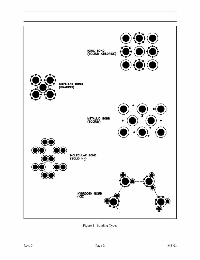
Figure 1 Bonding Types
Rev. 0 Page 3 MS-01

Solids have greater interatomic attractions than liquids and gases. However, there are widevariations in the properties of solid materials used for engineering purposes. The properties ofmaterials depend on their interatomic bonds. These same bonds also dictate the space betweenthe configuration of atoms in solids. All solids may be classified as either amorphous orcrystalline.
Amorphous materials have no regular arrangement of their molecules. Materials like glassand paraffin are considered amorphous. Amorphous materials have the properties ofsolids. They have definite shape and volume and diffuse slowly. These materials alsolack sharply defined melting points. In many respects, they resemble liquids that flowvery slowly at room temperature.
In a crystalline structure, the atoms are arranged in a three-dimensional array called alattice. The lattice has a regular repeating configuration in all directions. A group ofparticles from one part of a crystal has exactly the same geometric relationship as a groupfrom any other part of the same crystal.
MS-01 Page 4 Rev. 0

The important information in this chapter is summarized below.
Types of Bonds and Their Characteristics
Ionic bond - An atom with one or more electrons are wholly transferred from oneelement to another, and the elements are held together by the force of attractiondue to the opposite polarity of the charge.
Covalent bond - An atom that needs electrons to complete its outer shell sharesthose electrons with its neighbor.
Metallic bond - The atoms do not share or exchange electrons to bond together.Instead, many electrons (roughly one for each atom) are more or less free to movethroughout the metal, so that each electron can interact with many of the fixedatoms.
Molecular bond - When neutral atoms undergo shifting in centers of their charge,they can weakly attract other atoms with displaced charges. This is sometimescalled the van der Waals bond.
Hydrogen bond - This bond is similar to the molecular bond and occurs due to theease with which hydrogen atoms displace their charge.
Order in Microstructures
Amorphous microstructures lack sharply defined melting points and do not havean orderly arrangement of particles.
Crystalline microstructures are arranged in three-dimensional arrays called lattices.
Rev. 0 Page 5 MS-01
COMMON LATTICE TYPES
All metals used in a reactor have crystalline structures. Crystallinemicrostructures are arranged in three-dimensional arrays called lattices. Thischapter will discuss the three most common lattice structures and theircharacteristics.
EO 1.2 DEFINE the following terms:
a. Crystal structureb. Body-centered cubic structurec. Face-centered cubic structured. Hexagonal close-packed structure
EO 1.3 STATE the three lattice-type structures in metals.
EO 1.4 Given a description or drawing, DISTINGUISH between thethree most common types of crystalline structures.
EO 1.5 IDENTIFY the crystalline structure possessed by a metal.
In metals, and in many other solids, the atoms are arranged in regular arrays called crystals. Acrystal structure consists of atoms arranged in a pattern that repeats periodically in athree-dimensional geometric lattice. The forces of chemical bonding causes this repetition. Itis this repeated pattern which control properties like strength, ductility, density (described inModule 2, Properties of Metals), conductivity (property of conducting or transmitting heat,electricity, etc.), and shape.
In general, the three most common basic crystal patterns associated with metals are: (a) thebody-centered cubic, (b) the face-centered cubic, and (c) the hexagonal close-packed. Figure 2shows these three patterns.
In a body-centered cubic (BCC) arrangement of atoms, the unit cell consists of eightatoms at the corners of a cube and one atom at the body center of the cube.
MS-01 Page 6 Rev. 0

In a face-centered cubic (FCC) arrangement of atoms, the unit cell consists of eight atomsat the corners of a cube and one atom at the center of each of the faces of the cube.
In a hexagonal close-packed (HCP) arrangement of atoms, the unit cell consists of threelayers of atoms. The top and bottom layers contain six atoms at the corners of a hexagonand one atom at the center of each hexagon. The middle layer contains three atomsnestled between the atoms of the top and bottom layers, hence, the name close-packed.
Figure 2 Common Lattice Types
Most diagrams ofthe structural cellsfor the BCC andFCC forms of ironare drawn asthough they are ofthe same size, asshown in Figure 2,but they are not.I n t h e B C Carrangement, thestructural cell,which uses onlynine atoms, ismuch smaller.
Rev. 0 Page 7 MS-01

Metals such as α-iron (Fe) (ferrite), chromium (Cr), vanadium (V), molybdenum (Mo), andtungsten (W) possess BCC structures. These BCC metals have two properties in common, highstrength and low ductility (which permits permanent deformation). FCC metals such as γ-iron(Fe) (austenite), aluminum (Al), copper (Cu), lead (Pb), silver (Ag), gold (Au), nickel (Ni),platinum (Pt), and thorium (Th) are, in general, of lower strength and higher ductility than BCCmetals. HCP structures are found in beryllium (Be), magnesium (Mg), zinc (Zn), cadmium (Cd),cobalt (Co), thallium (Tl), and zirconium (Zr).
The important information in this chapter is summarized below.
A crystal structure consists of atoms arranged in a pattern that repeats periodicallyin a three-dimensional geometric lattice.
Body-centered cubic structure is an arrangement of atoms in which the unit cellconsists of eight atoms at the corners of a cube and one atom at the body centerof the cube.
Face-centered cubic structure is an arrangement of atoms in which the unit cellconsists of eight atoms at the corners of a cube and one atom at the center of eachof the six faces of the cube.
Hexagonal close-packed structure is an arrangement of atoms in which the unitcell consists of three layers of atoms. The top and bottom layers contain six atomsat the corners of a hexagon and one atom at the center of each hexagon. Themiddle layer contains three atoms nestled between the atoms of the top and bottomlayers.
Metals containing BCC structures include ferrite, chromium, vanadium,molybdenum, and tungsten. These metals possess high strength and low ductility.
Metals containing FCC structures include austenite, aluminum, copper, lead, silver,gold, nickel, platinum, and thorium. These metals possess low strength and highductility.
Metals containing HCP structures include beryllium, magnesium, zinc, cadmium,cobalt, thallium, and zirconium. HCP metals are not as ductile as FCC metals.
MS-01 Page 8 Rev. 0

GRAIN STRUCTURE AND BOUNDARY
Metals contain grains and crystal structures. The individual needs a microscopeto see the grains and crystal structures. Grains and grain boundaries helpdetermine the properties of a material.
EO 1.6 DEFINE the following terms:
a. Grain b. Grain structurec. Grain boundaryd. Creep
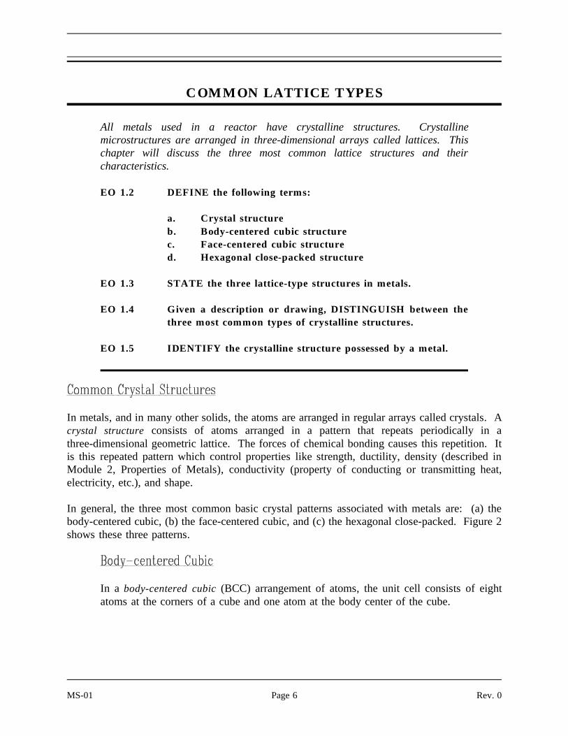
If you were to take a small section of a common metal and examine it under a microscope, youwould see a structure similar to that shown in Figure 3(a). Each of the light areas is called agrain, or crystal, which is the region of space occupied by a continuous crystal lattice. The darklines surrounding the grains are grain boundaries. The grain structure refers to the arrangementof the grains in a metal, with a grain having a particular crystal structure.
The grain boundary refers to the outside area of a grain that separates it from the other grains.The grain boundary is a region of misfit between the grains and is usually one to three atomdiameters wide. The grain boundaries separate variously-oriented crystal regions(polycrystalline) in which the crystal structures are identical. Figure 3(b) represents four grainsof different orientation and the grain boundaries that arise at the interfaces between the grains.
A very important feature of a metal is the average size of the grain. The size of the graindetermines the properties of the metal. For example, smaller grain size increases tensile strengthand tends to increase ductility. A larger grain size is preferred for improved high-temperaturecreep properties. Creep is the permanent deformation that increases with time under constantload or stress. Creep becomes progressively easier with increasing temperature. Stress andstrain are covered in Module 2, Properties of Metals, and creep is covered in Module 5, PlantMaterials.
Rev. 0 Page 9 MS-01
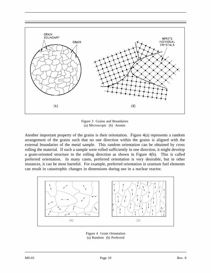
Another important property of the grains is their orientation. Figure 4(a) represents a random
Figure 3 Grains and Boundaries(a) Microscopic (b) Atomic
arrangement of the grains such that no one direction within the grains is aligned with theexternal boundaries of the metal sample. This random orientation can be obtained by crossrolling the material. If such a sample were rolled sufficiently in one direction, it might developa grain-oriented structure in the rolling direction as shown in Figure 4(b). This is calledpreferred orientation. In many cases, preferred orientation is very desirable, but in otherinstances, it can be most harmful. For example, preferred orientation in uranium fuel elementscan result in catastrophic changes in dimensions during use in a nuclear reactor.
Figure 4 Grain Orientation(a) Random (b) Preferred
MS-01 Page 10 Rev. 0

The important information in this chapter is summarized below.
Grain is the region of space occupied by a continuous crystal lattice.
Grain structure is the arrangement of grains in a metal, with a grain having aparticular crystal structure.
Grain boundary is the outside area of grain that separates it from other grains.
Creep is the permanent deformation that increases with time under constant loador stress.
Small grain size increases tensile strength and ductility.
Rev. 0 Page 11 MS-01

POLYM ORPHISM
Metals are capable of existing in more than one form at a time. This chapter willdiscuss this property of metals.
EO 1.7 DEFINE the term polymorphism.
EO 1.8 IDENTIFY the ranges and names for the three polymorphismphases associated with uranium metal.
EO 1.9 IDENTIFY the polymorphism phase that prevents pureuranium from being used as fuel.
Polymorphism is the property
Figure 5 Cooling Curve for Unalloyed Uranium
or ability of a metal to exist intwo or more crystalline formsdepending upon temperatureand composition. Most metalsand metal alloys exhibit thisproperty. Uranium is a goodexample of a metal thatexhibi ts polymorphism.Uranium metal can exist inthree different crystallinestructures. Each structureexists at a specific phase, asillustrated in Figure 5.
1. The alpha phase, from room temperature to 663°C
2. The beta phase, from 663°C to 764°C
3. The gamma phase, from 764°C to its melting point of 1133°C
MS-01 Page 12 Rev. 0

The alpha (α) phase is stable at room temperature and has a crystal system characterizedby three unequal axes at right angles.
In the alpha phase, the properties of the lattice are different in the X, Y, and Z axes.This is because of the regular recurring state of the atoms is different. Because of thiscondition, when heated the phase expands in the X and Z directions and shrinks in theY direction. Figure 6 shows what happens to the dimensions (Å = angstrom, onehundred-millionth of a centimeter) of a unit cell of alpha uranium upon being heated.
As shown, heating and cooling of alpha phase uranium can lead to drastic dimensionalchanges and gross distortions of the metal. Thus, pure uranium is not used as a fuel,but only in alloys or compounds.
Figure 6 Change in Alpha Uranium Upon Heating From 0 to 300°C
The beta (β) phase of uranium occurs at elevated temperatures. This phase has atetragonal (having four angles and four sides) lattice structure and is quite complex.
Rev. 0 Page 13 MS-01

The gamma (γ) phase of uranium is formed at temperatures above those required forbeta phase stability. In the gamma phase, the lattice structure is BCC and expandsequally in all directions when heated.
Two additional examples of polymorphism are listed below.
1. Heating iron to 907°C causes a change from BCC (alpha, ferrite) ironto the FCC (gamma, austenite) form.
2. Zirconium is HCP (alpha) up to 863°C, where it transforms to the BCC(beta, zirconium) form.
The properties of one polymorphic form of the same metal will differ from those of anotherpolymorphic form. For example, gamma iron can dissolve up to 1.7% carbon, whereas alphairon can dissolve only 0.03%.
The important information in this chapter is summarized below.
Polymorphism is the property or ability of a metal to exist in two or morecrystalline forms depending upon temperature and composition.
Metal can exist in three phases or crystalline structures.
Uranium metal phases are:
Alpha - Room temperature to 663°C
Beta - 663°C to 764°C
Gamma - 764°C to 1133°C
Alpha phase prevents pure uranium from being used as fuel because ofexpansion properties.
MS-01 Page 14 Rev. 0

ALLOYS
Most of the materials used in structural engineering or component fabrication aremetals. Alloying is a common practice because metallic bonds allow joining ofdifferent types of metals.
EO 1.10 DEFINE the term alloy.
EO 1.11 DESCRIBE an alloy as to the three possible microstructuresand the two general characteristics as compared to pure metals.
EO 1.12 IDENTIFY the two desirable properties of type 304 stainlesssteel.
An alloy is a mixture of two or more materials, at least one of which is a metal. Alloys canhave a microstructure consisting of solid solutions, where secondary atoms are introduced assubstitutionals or interstitials (discussed further in the next chapter and Module 5, PlantMaterials) in a crystal lattice. An alloy might also be a crystal with a metallic compound at eachlattice point. In addition, alloys may be composed of secondary crystals imbedded in a primarypolycrystalline matrix. This type of alloy is called a composite (although the term "composite"does not necessarily imply that the component materials are metals). Module 2, Properties ofMetals, discusses how different elements change the physical properties of a metal.
Alloys are usually stronger than pure metals, although they generally offer reduced electrical andthermal conductivity. Strength is the most important criterion by which many structuralmaterials are judged. Therefore, alloys are used for engineering construction. Steel, probablythe most common structural metal, is a good example of an alloy. It is an alloy of iron andcarbon, with other elements to give it certain desirable properties.
As mentioned in the previous chapter, it is sometimes possible for a material to be composedof several solid phases. The strengths of these materials are enhanced by allowing a solidstructure to become a form composed of two interspersed phases. When the material in questionis an alloy, it is possible to quench (discussed in more detail in Module 2, Properties of Metals)the metal from a molten state to form the interspersed phases. The type and rate of quenchingdetermines the final solid structure and, therefore, its properties.
Rev. 0 Page 15 MS-01
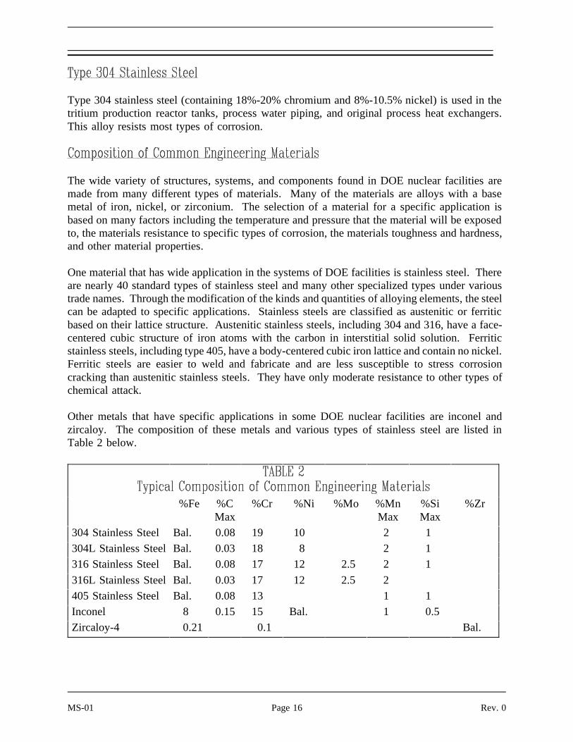
Type 304 stainless steel (containing 18%-20% chromium and 8%-10.5% nickel) is used in thetritium production reactor tanks, process water piping, and original process heat exchangers.This alloy resists most types of corrosion.
The wide variety of structures, systems, and components found in DOE nuclear facilities aremade from many different types of materials. Many of the materials are alloys with a basemetal of iron, nickel, or zirconium. The selection of a material for a specific application isbased on many factors including the temperature and pressure that the material will be exposedto, the materials resistance to specific types of corrosion, the materials toughness and hardness,and other material properties.
One material that has wide application in the systems of DOE facilities is stainless steel. Thereare nearly 40 standard types of stainless steel and many other specialized types under varioustrade names. Through the modification of the kinds and quantities of alloying elements, the steelcan be adapted to specific applications. Stainless steels are classified as austenitic or ferriticbased on their lattice structure. Austenitic stainless steels, including 304 and 316, have a face-centered cubic structure of iron atoms with the carbon in interstitial solid solution. Ferriticstainless steels, including type 405, have a body-centered cubic iron lattice and contain no nickel.Ferritic steels are easier to weld and fabricate and are less susceptible to stress corrosioncracking than austenitic stainless steels. They have only moderate resistance to other types ofchemical attack.
Other metals that have specific applications in some DOE nuclear facilities are inconel andzircaloy. The composition of these metals and various types of stainless steel are listed inTable 2 below.
%Fe %CMax
%Cr %Ni %Mo %MnMax
%SiMax
%Zr
304 Stainless Steel Bal. 0.08 19 10 2 1
304L Stainless Steel Bal. 0.03 18 8 2 1
316 Stainless Steel Bal. 0.08 17 12 2.5 2 1
316L Stainless Steel Bal. 0.03 17 12 2.5 2
405 Stainless Steel Bal. 0.08 13 1 1
Inconel 8 0.15 15 Bal. 1 0.5
Zircaloy-4 0.21 0.1 Bal.
MS-01 Page 16 Rev. 0

The important information in this chapter is summarized below.
An alloy is a mixture of two or more materials, at least one of which is a metal.
Alloy microstructures
Solid solutions, where secondary atoms introduced as substitutionals orinterstitials in a crystal lattice.
Crystal with metallic bonds
Composites, where secondary crystals are imbedded in a primarypolycrystalline matrix.
Alloys are usually stronger than pure metals although alloys generally havereduced electrical and thermal conductivities than pure metals.
The two desirable properties of type 304 stainless steel are corrosion resistanceand high toughness.
Rev. 0 Page 17 MS-01

IMPERFECTIONS IN METALS
The discussion of order in microstructures in the previous chapters assumedidealized microstructures. In reality, materials are not composed of perfectcrystals, nor are they free of impurities that alter their properties. Evenamorphous solids have imperfections and impurities that change their structure.
EO 1.13 IDENTIFY the three types of microscopic imperfections foundin crystalline structures.
EO 1.14 STATE how slip occurs in crystals.
EO 1.15 IDENTIFY the four types of bulk defects.
Microscopic imperfections are generally classified as either point, line, or interfacialimperfections.
1. Point imperfections have atomic dimensions.
2. Line imperfections or dislocations are generally many atoms in length.
3. Interfacial imperfections are larger than line defects and occur over a two-dimensional area.
Point imperfections in crystals can be divided into three main defect categories. Theyare illustrated in Figure 7.
1. Vacancy defects result from a missing atom in a lattice position. Thevacancy type of defect can result from imperfect packing during thecrystallization process, or it may be due to increased thermal vibrationsof the atoms brought about by elevated temperature.
2. Substitutional defects result from an impurity present at a lattice position.
3. Interstitial defects result from an impurity located at an interstitial site orone of the lattice atoms being in an interstitial position instead of beingat its lattice position. Interstitial refers to locations between atoms in alattice structure.
MS-01 Page 18 Rev. 0

Interstitial impurities called network modifiers act as point defects inamorphous solids. The presence of point defects can enhance or lessenthe value of a material for engineering construction depending upon theintended use.
Figure 7 Point Defects
Figure 8 Line Defects (Dislocations)
Line imperfections are called dislocationsand occur in crystalline materials only.Dislocations can be an edge type, screwtype, or mixed type, depending on howthey distort the lattice, as shown inFigure 8. It is important to note thatdislocations cannot end inside a crystal.They must end at a crystal edge or otherdislocation, or they must close back onthemselves.
Edge dislocations consist of an extra rowor plane of atoms in the crystal structure.The imperfection may extend in a straightline all the way through the crystal or itmay follow an irregular path. It mayalso be short, extending only a smalldistance into the crystal causing a slip ofone atomic distance along the glide plane(direction the edge imperfection ismoving).
Rev. 0 Page 19 MS-01
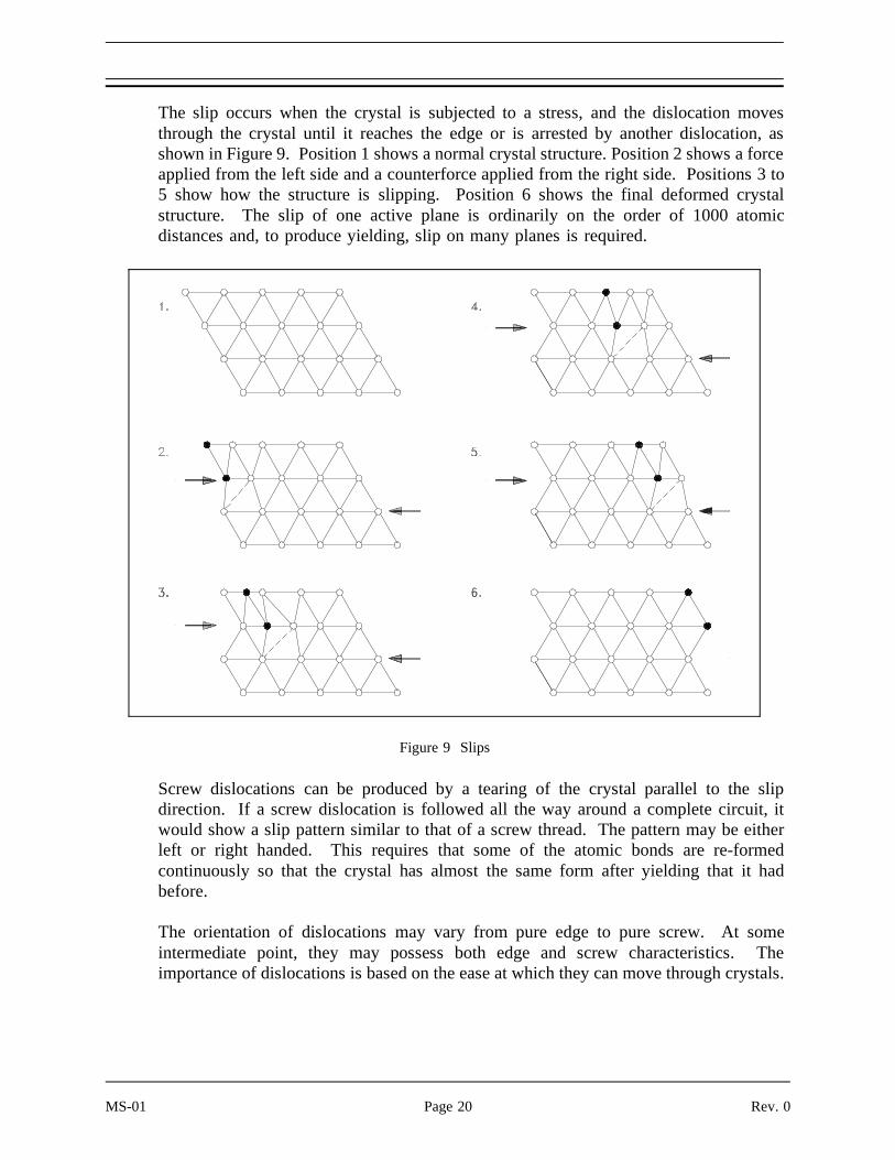
The slip occurs when the crystal is subjected to a stress, and the dislocation movesthrough the crystal until it reaches the edge or is arrested by another dislocation, asshown in Figure 9. Position 1 shows a normal crystal structure. Position 2 shows a forceapplied from the left side and a counterforce applied from the right side. Positions 3 to5 show how the structure is slipping. Position 6 shows the final deformed crystalstructure. The slip of one active plane is ordinarily on the order of 1000 atomicdistances and, to produce yielding, slip on many planes is required.
Screw dislocations can be produced by a tearing of the crystal parallel to the slip
Figure 9 Slips
direction. If a screw dislocation is followed all the way around a complete circuit, itwould show a slip pattern similar to that of a screw thread. The pattern may be eitherleft or right handed. This requires that some of the atomic bonds are re-formedcontinuously so that the crystal has almost the same form after yielding that it hadbefore.
The orientation of dislocations may vary from pure edge to pure screw. At someintermediate point, they may possess both edge and screw characteristics. Theimportance of dislocations is based on the ease at which they can move through crystals.
MS-01 Page 20 Rev. 0

Interfacial imperfections exist at an angle between any two faces of a crystal or crystalform. These imperfections are found at free surfaces, domain boundaries, grainboundaries, or interphase boundaries. Free surfaces are interfaces between gases andsolids. Domain boundaries refer to interfaces where electronic structures are differenton either side causing each side to act differently although the same atomic arrangementexists on both sides. Grain boundaries exist between crystals of similar lattice structurethat possess different spacial orientations. Polycrystalline materials are made up of manygrains which are separated by distances typically of several atomic diameters. Finally,interphase boundaries exist between the regions where materials exist in different phases(i.e., BCC next to FCC structures).
Three-dimensional macroscopic defects are called bulk defects. They generally occur on a muchlarger scale than the microscopic defects. These macroscopic defects generally are introducedinto a material during refinement from its raw state or during fabrication processes.
The most common bulk defect arises from foreign particles being included in the prime material.These second-phase particles, called inclusions, are seldom wanted because they significantlyalter the structural properties. An example of an inclusion may be oxide particles in a puremetal or a bit of clay in a glass structure.
Other bulk defects include gas pockets or shrinking cavities found generally in castings. Thesespaces weaken the material and are therefore guarded against during fabrication. The workingand forging of metals can cause cracks that act as stress concentrators and weaken the material.Any welding or joining defects may also be classified as bulk defects.
Rev. 0 Page 21 MS-01

The important information in this chapter is summarized below.
Microscopic Imperfections
Point imperfections are in the size range of individual atoms.
Line (dislocation) imperfections are generally many atoms in length. Lineimperfections can be of the edge type, screw type, or mixed type, depending onlattice distortion. Line imperfections cannot end inside a crystal; they must endat crystal edge or other dislocation, or close back on themselves.
Interfacial imperfections are larger than line imperfections and occur over a twodimensional area. Interfacial imperfections exist at free surfaces, domainboundaries, grain boundaries, or interphase boundaries.
Slip occurs when a crystal is subjected to stress and the dislocations marchthrough the crystal until they reach the edge or are arrested by anotherdislocation.
Macroscopic Defects
Bulk defects are three dimensional defects.
Foreign particles included in the prime material (inclusions) are mostcommon bulk defect
Gas pockets
Shrinking cavities
Welding or joining defects
MS-01 Page 22 Rev. 0