materials challenges for fossil-fuelled power plant · materials challenges for fossil-fuelled...
TRANSCRIPT

Energy Materials
MATERIALS CHALLENGES FOR FOSSIL-FUELLED POWER PLANT
Derek AllenAlstom Power

Energy Materials
Fossil fuels in the energy portfolio

Energy Materials
Projections

Energy MaterialsZERO-EMISSIONS
TWIN-TRACK APPROACHCarbon
Reduction
Time
Near-term Mid-term Long-term
Improved efficiency
Efficiency + CCS
COST

Energy Materials
1960 1980 2000 2020
35
40
45
50
55
30
Supercritical Boilers/turbines
Sub Critical Boilers
Plant efficiency
% NCV
Year
Target AD700
50 – 55%
46%
Meri PoriHemweg
New Chinese Orders
42%
Chinese fleet 38%
OldPlants 30%
Increasing Efficiency
Lower CO2
emissionsAvailable Advanced Supercritical Technology being offered
NOW
38%
32%
UK/US
fleet
Emissions Reduction by Improvements In Plant Efficiency

Energy Materials
Carbon Capture and Storage
Energy Materials
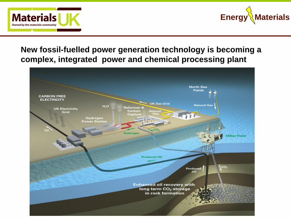
New fossil-fuelled power generation technology is becoming a complex, integrated power and chemical processing plant

Energy Materials
Key Challenges Facing Fossil Power Plant Materials
• Life extension of existing plants
•Increasing Temperatures
• The aggressive nature of the environment particularly for CCS plant options

Energy Materials
Steam turbine materials
9
Operation at higher temperatures• Improved creep performance• More aggressive environment• More demanding surface properties (steam
oxidation, wear)-coatings development
Enable more aerodynamic steam path• Highly stressed low temperature steam path• Stronger rotors and blades coupled with
resistance to SCC
Incremental developments are vital

Energy Materials
Boiler materials
•Ferritic materials with operational temperatures to 650C either through intrinsic properties or a combination of this and surface engineering
•Austenitic materials capable of temperatures up to 700C and then beyond
•Superalloys materials capable of temperatures up to 750C and beyond in aggressive environments
•Materials modelling capabilities to reduce lead time for new alloys to hit the market place

Energy Materials
Gas Turbine Materials• Higher temperature blading/combustors
– Thermal cycling
• Combustor & blading alloys for aggressive environments
• Coatings (corrosion, oxidation, TBC, SMART) • Stronger disc alloys• Lightweighting (last stage blading)

Energy Materials
Post Combustion Capture – Amine Scrubbing
Materials and related issues
• Scale-up to power plant requirements• Durability of scrubber• Life of amine solvent • Operational flexibility
CO2 recovery from flue gas with chemical solvent (MEA)

Energy Materials
Oxy-Combustion – Pulverised Coal PlantsMaterials and related issues
•Water wall and superheatermaterials – fouling, slaggingand corrosion• Concentration of contaminants with flue gas recycling• CO2/H2O condenser durability• Contaminants in the CO2stream for disposal
30 MWth Schwarze Pumpe (Vattenfall) Pilot Plant

Energy Materials
Entrained Flow Gasification – with CO2 Capture
COAL SLURRY& OXYGEN
SLAG
QUENCH MAKE-UP
RECYCLE OF HEAT FOR UPGRADING
DESATURATOR
COLD MAKE-UP WATER
SYNGAS FUEL
SHIFT REACTOR
HP STEAM
BFW
BFW
LP STEAM
SULPHUR
CARBON DIOXIDE.
Materials and related issues
• Syngas cooler conditions• Syngas cooler materials• Gasifier refractory linings• Gas cleaning technology options• Gas turbine durability• H2 separation membranes
Pd/AgPolymerCeramic
Energy Materials
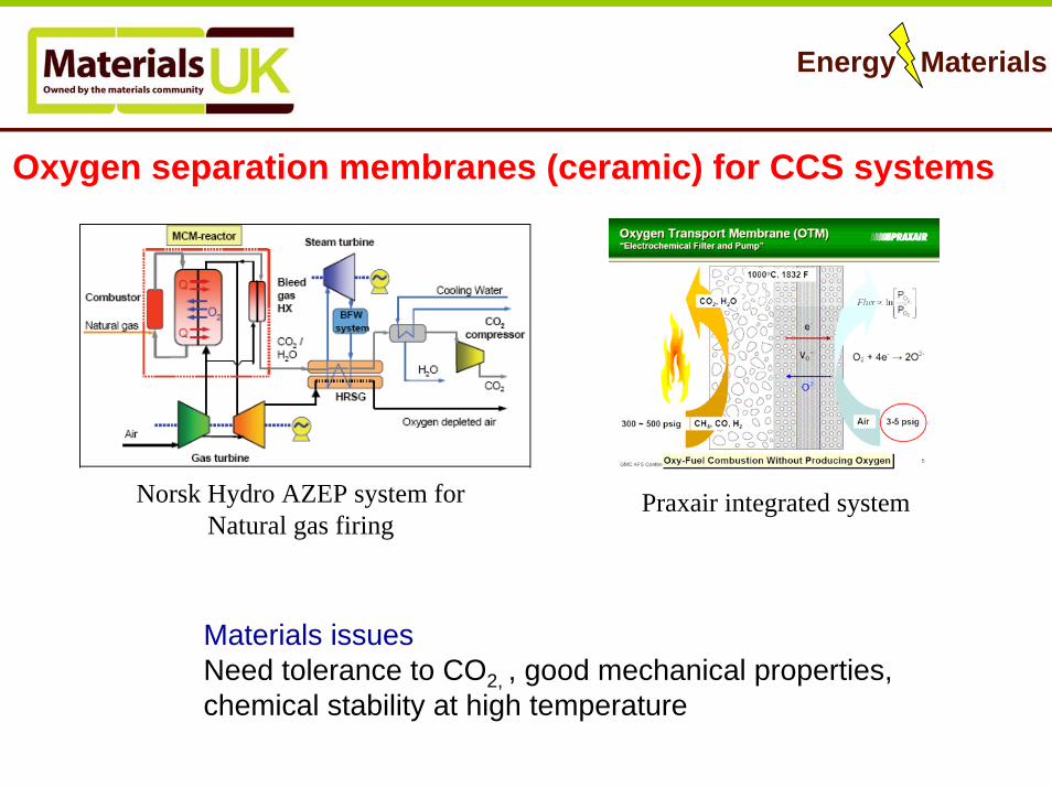
Oxygen separation membranes (ceramic) for CCS systems
Norsk Hydro AZEP system forNatural gas firing
Praxair integrated system
Materials issuesNeed tolerance to CO2, , good mechanical properties, chemical stability at high temperature

Energy Materials
CO2 Transport - pipelines
CO2 pipelines:3500 km in use today Capacity > 45 Mt/y
WeyburnPipeline length 325 km19 MtCO2 over 15 years of EOR.
Materials and related issues• Pipeline/compressor materials –corrosion• Corrosion inhibitors• CO2 contaminant levels Photo: Dakota Gasification

Energy Materials
SUMMARY
• Improved efficiency of ‘Conventional’ and existing plant– High temp materials & coatings– Life extension & modelling (full life cycle)– Low cost manufacture & processing– Incremental developments are important
• New plant-including CCS– Aggressive environments– High Temp– Novel materials development (eg filters, membranes, sorbents)
• Disruptive technologies– Life cycle considerations

Energy Materials
Materials challenges in power generation by nuclear fission
Alan TurnbullNPL

Energy Materials
Nuclear fission - civil

Energy Materials
Nuclear fission - civil440 nuclear plants in 31 countries; about 30 plants currently being constructed, mostly PWR. China is proposing to start building 25nuclear plants in next 5 years – includes pebble-bed HTR
UK: Magnox reactors →2010?; AGRs →2023?; Sizewell PWR →2040s
Commitment to nuclear submarine new-build reactors but not yet civil
In short term, any new UK civil plant will be “off-the-shelf” evolutionary PWR design with 60-year+ life expectancy
Westinghouse 1100 MW AP1000? o 50% fewer valves; 83% less piping, 35% fewer pumps etc….
European Pressurised Water Reactor 1600 MW?o Innovative design features to prevent core meltdown (no power or
switching required)

Energy MaterialsNuclear fission –UK reactor types

Energy Materials
Statement from a 2004 Nuclear Energy Institute (NEI) presentation to U.S. utility management(courtesy of EPRI)
“Primary system materials will degrade at your plant”
The problem can be characterised:What is going to crack next?Where will it crack?When?Can you live with it?
0
1
2
3
1 2 3Knowledge
Deg
rada
tion
Susc
eptib
ility
Response to
Proactive Actions

Energy Materials
Nuclear fission –PW reactor
Inlet water 290 °C Outlet water 325 °C
H2, LiOH, H3BO3, O2<10ppbpH=6.8 – 7.4 at 300°C

Energy Materials
Nuclear fission – irradiationNeutron irradiation can generate point defects in metals and lead to transmutation of some elements
In the case of low-alloy steels, neutron irradiation induces hardening and embrittlement as a function of :
Irradiation temperaturelevel of impurities (Cu, P …)
RPV internals materials are subjected to a very high fluence(up to 1000 times the fluence on the RPV wall) which leads to major modifications of their properties
Hardening (YS can be multiplied by 5)Decrease in ductility and toughnessChanges in microstructure (grain boundary chemistry, dislocationdensity and intragranular precipitates)

Energy Materials
Nuclear fission – PWR (courtesy of Areva NP)Voids and helium/hydrogen bubbles in a baffle-bolt extracted from Tihange 1 (TEM
examinations – PNNL)
Cavities in 316 SS

Energy Materials
Degradation of core internals
Potential degradation mechanisms for irradiated stainless steel and nickel alloy core components include
-irradiation embrittlement-void swelling-irradiation assisted SCC
IASCC has caused a number of failures-baffle-former bolts-control rod cladding
CRACKING IN PWR BAFFLE FORMER BOLT
Energy Materials
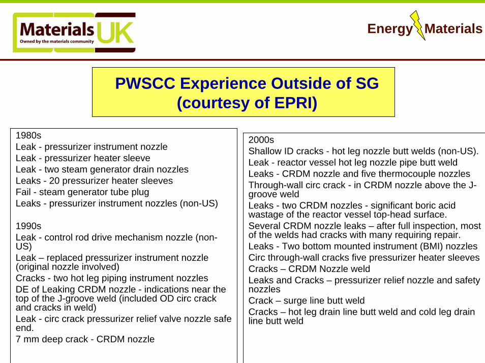
PWSCC Experience Outside of SG(courtesy of EPRI)
1980sLeak - pressurizer instrument nozzle Leak - pressurizer heater sleeveLeak - two steam generator drain nozzlesLeaks - 20 pressurizer heater sleevesFail - steam generator tube plugLeaks - pressurizer instrument nozzles (non-US)
1990sLeak - control rod drive mechanism nozzle (non-US)Leak – replaced pressurizer instrument nozzle (original nozzle involved)Cracks - two hot leg piping instrument nozzlesDE of Leaking CRDM nozzle - indications near the top of the J-groove weld (included OD circ crack and cracks in weld)Leak - circ crack pressurizer relief valve nozzle safe end.7 mm deep crack - CRDM nozzle
2000sShallow ID cracks - hot leg nozzle butt welds (non-US).Leak - reactor vessel hot leg nozzle pipe butt weldLeaks - CRDM nozzle and five thermocouple nozzlesThrough-wall circ crack - in CRDM nozzle above the J-groove weldLeaks - two CRDM nozzles - significant boric acid wastage of the reactor vessel top-head surface.Several CRDM nozzle leaks – after full inspection, most of the welds had cracks with many requiring repair. Leaks - Two bottom mounted instrument (BMI) nozzlesCirc through-wall cracks five pressurizer heater sleevesCracks – CRDM Nozzle weldLeaks and Cracks – pressurizer relief nozzle and safety nozzlesCrack – surge line butt weldCracks – hot leg drain line butt weld and cold leg drain line butt weld

Energy Materials
Nuclear fission –Steam generator
NH3, N2H4, morpholine, O2<3ppbpH=9.2 – 10.0 at 25°C

Energy Materials
Nuclear fission –Steam generator(courtesy Areva NP)
Plugged tubes in France in 1999
IGA + IGSCC
PWSCC in roll
transition
AVB Fretting
Fractured TSP Loose
parts
Strictions
Other
Small radiusU-Bends PWSCC
U-Bends Fatigue

Energy Materials
Nuclear fission –PWR challengesEIC: design & fabrication factors; start-up/shut-down; water chemistry
transients, occluded regions; irradiation induced stress corrosion cracking; corrosion fatigue; corrosion-erosion
Thermal fatigue; thermal ageing; irradiation toughness loss; void swelling Monitoring of strain, temperature and chemistry would be idealRisk-based management+NDE (considered at design stage)Multi-scale modelling critical
Energy Materials
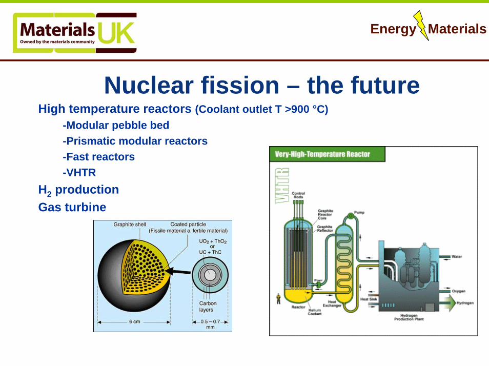
Nuclear fission – the futureHigh temperature reactors (Coolant outlet T >900 °C)
-Modular pebble bed-Prismatic modular reactors-Fast reactors-VHTR
H2 productionGas turbine

Energy Materials
Nuclear fission – the future
High temperature reactors - Material needs
Materials lifetime at elevated temperaturesReactor pressure vesselInternals componentsHot gas ducts and componentsImpurities in He gasDimensional behaviour of graphiteat high fluences

Energy Materials
Nuclear fission – Other issuesSteam turbines
Higher temperature inlet steamHigher strength blades in last stage LP turbine
Waste containment

Energy Materials
Workshop on energy materials, DTI 24/11/06
Fusion Materials
Drivers, Challenges and OpportunitiesSynergies With Other Areas
Barriers
Ian CookEURATOM/UKAEA Fusion Association
(See: I. Cook, ‘Materials research for fusion energy’, Nat. Mat. 5, 77-80, Feb. 2006.)

Energy Materials
Drivers (1)“Fast Track” commercialisation of fusion will bring a large payoff:
•Almost unlimited fuel
•Competitive economics
•No significant emissions
•No potential for major accidents
•Only short-lived waste.
So, a big contribution to:
•World economic development, while avoiding dangerous climate change.
•Energy security.

Energy Materials
Drivers (2)
Huge progress in fusion science and technology
Fusion has just passed a major decision point:•We are taking the ‘Next Step’ - ITER•In addition, there is a major materials initiative
This marks the transition from the ‘research’ phase of fusion power development to the ‘demonstration’ phase

European Fusion Fast Track Strategy(The ‘King Report’ to the EU Council of Ministers, 2002)
JET and other
existing devices
ITER
IFMIF
(Materials
testing)
DEMO(s) Commercial
Plants
Concept improvements
Other technology

Energy Materials
ITER• Integrated physics and engineering on the scale of a power station
• Key technologies have been fabricated and tested by industry
• 500 MW
• Europe, Japan, Russia, China, India, USA and South Korea.
• Construction has begun at Cadarache in France.
•Treaty signed on Tuesday, in the Elysee Palace.

Energy Materials
ITER will address many materials issues
•Effects of fluxes of particles and energy on plasma-facing materials.
•Short-term effects of fusion neutrons on materials.
•Corrosion, permeation and stress-related phenomena in materials.
•Many others.

Energy Materials
Some materials issues cannot be addressed by ITER
ITER cannot address:•Damaging effects of many years exposure to fusion neutrons•Associated development of alloys &composites.
To address these challenges, we need to:•Construct IFMIF, the fusion neutron source, quickly and use it to test the most promising materials.•Develop real understanding, and models with predictive capability, to optimise the initial choice of alloys to be tested, and to extrapolate from IFMIF results to DEMO.

Energy Materials
IFMIF
0 20 40m
Ion Source
RFQ
High Energy BeamTransport
Li Loop
Test Cell: Target & Test Modules
PIE Facilities
0 20 40m
Ion Source
RFQ
High Energy BeamTransport
Li Loop
Test Cell: Target & Test Modules
PIE Facilities
Accelerated completion of the design of IFMIF: JP/EU treaty, agreed on Wednesday in Brussels.

Roles of modelling and validation in the fast trackfusion materials development programme
Non-fusion materials tests
Modelling and validation experiments
Tests in IFMIF
Tests in ITER TBMs
Selection of materials for:
Evolving DEMO designs DEMOs
5 years 12 years
Micro- to meso-scopic
interpretation & guidance on optimisation
Development of real predictive capability – to minimise
uncertainties in extrapolation to DEMO, & for licensing

Energy Materials
Main R&D Priorities
First priorities are the following promising materials:•Ferritic-martensitic steels (neutron–resistant structural materials); Oxide-dispersion-strengthened steels.•Tungsten-based (plasma-facing material).
These are body-centred-cubic (bcc). So are chromium, molybdenum, tantalum, vanadium and niobium: all of which have fusion interest, either as alloying elements or in niche roles.So, we primarily study the bcc metals and alloys! Comparisons between these are also of great scientific value.
A wide variety of other materials, including ceramics, are also relevant.

Energy Materials
Opportunities
Real predictive modelling capability, based on understanding, is rapidly becoming possible. We are going through a phase change in this respect. Transatlantically competitive!
Needs experimental facilities (e.g. multi-ion-beam irradiations, TEM) for inexpensive clever model validation.
Can accelerate and cheapen materials design and optimisation, and permit licensing without the need for excessive design conservatism.
These developments have major potential in other areas.

Identification of Material Damage ‘Viruses’
Systematic quantum-mechanical calculations of small interstitial defects in the body-centred cubic metals.
Has revealed anomalous nature of defects in iron: driven by magnetism.
These are the ‘viruses’ of irradiation-driven materials damage.
May always be inaccessible to observation.
Structures and energies from calculations used:
As input to constructing correct interatomicpotentials for molecular dynamics.
As input to kinetic Monte Carlo modelling, on the mesoscale.

Energy Materials
New interatomic potential for magnetic iron
Defect configuration
‘Ab initio’calculation
Calculated from Potential
100 4.64eV 4.60eV111 4.34eV 4.24eV110 3.64eV 3.65eV
[Note that in the previous viewgraph, the 111 value has been set as the zero.]
•New quantum-mechanics-based classical interatomic potentials.
•Allows accurate efficient simulations on million-atom scale.
•Significant result, likely to have implications in other fields.

Example results from the new potential
The distribution of magnetic moment (above) and pressure (below) around a dislocation loop in iron.
Pressure and magnetisation are almost perfectly anticorrelated, highlighting the importance of magnetoelastic effects in the microscopic picture of radiation damage in iron and ferritic steel.

Energy Materials
Inhibiting Defect Migration
•Kinetic Monte Carlo and analytical investigations of effect of impurity atoms on migration of defect clusters in metals.
•Strong inhibition of diffusion – so defects are more likely to re-combine.
•May lead to ways of doping materials to suppress swelling etc.
Energy Materials
Ongoing Work
•Extending the modelling to alloys (iron-chromium, steels, tungsten alloys)
•Extending the modelling in theoretical scope (electronic effects, mesoscale modelling of defect evolution, dislocation mobility, phase changes).
•Validation of models to greatest possible extent. (Fission irradiations in European fusion programme. UKAEA-funded experimental programme at Oxford U. Prepare for interpretation of CEA/CNRS JANNUS multi-beam experiments, and facility to be set up at Salford U.)
All work will continue to be within integrated European programme.

Energy Materials
Main SynergiesFusion and fission are very different in most respects. However, there are strong synergies
in fission (Gens. 3.5 & 4) and fusion materials development:
• Similar underlying materials physics
• Similar candidate structural materials
• Similar desire for high temperature and long life in neutron bombardment
• Similar methods of theoretical and experimental investigation
• Similar need for real understanding
Joint approach would bring significant benefits. Benefits also to lifetime extension of existing plants and understanding the long time behaviour of fission repository waste.
More widely, synergies to materials for extreme environments (e.g. high heat flux.)

Energy Materials
Barriers
•Low funding levels*.
•No UK integrated (or even loosely co-ordinated) cross-cutting R,D&D programmes.
•Few facilities (especially in UK) for experimental validation.
* Total public-funded world annual spending on energy R&D is equal to one day of consumer spending on energy.