materials for automobiles - indian institute of technology madras
TRANSCRIPT
Materials for Automobiles
Lec 12
Cast Irons
3 Oct 2011
Plan
Foundry process
Gray Cast Iron
CGI
Ductile Iron
ADI

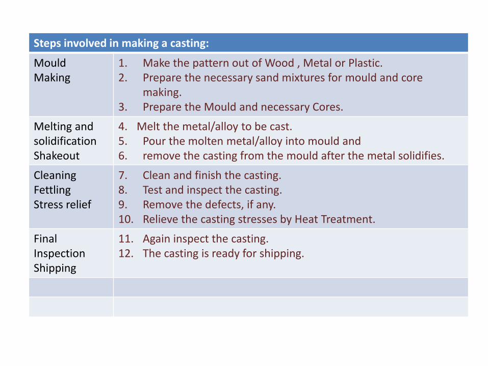
Steps involved in making a casting:
Mould Making
1. Make the pattern out of Wood , Metal or Plastic. 2. Prepare the necessary sand mixtures for mould and core
making. 3. Prepare the Mould and necessary Cores.
Melting and solidification Shakeout
4. Melt the metal/alloy to be cast. 5. Pour the molten metal/alloy into mould and 6. remove the casting from the mould after the metal solidifies.
Cleaning Fettling Stress relief
7. Clean and finish the casting. 8. Test and inspect the casting. 9. Remove the defects, if any. 10. Relieve the casting stresses by Heat Treatment.
Final Inspection Shipping
11. Again inspect the casting. 12. The casting is ready for shipping.


Advantages And Limitations of metal casting:
Adv • Casting is one of the most versatile manufacturing process.
• Casting provides the greatest freedom of design in terms of
shape, size and the product quantity.
• Casting imparts uniform directional properties and better
vibration capacity to the cast parts.
• Shapes difficult and uneconomic to obtain otherwise may be
achieved through casting process.
• A product may be cast as one piece, there by eliminating assembly. • Very heavy and bulky parts otherwise difficult to fabricate, may be
cast. • Metals (like cast iron) difficult to be shaped by other manufacturing
processes may be cast. • Casting can be designed for equal distribution of loads and for
minimum stress concentration . • Casting process can be mechanised for mass production
limitations • Dimensional accuracy and surface finish of the castings made by sand casting processes are a limitation to this technique.
• The metal casting process is a labor intensive process
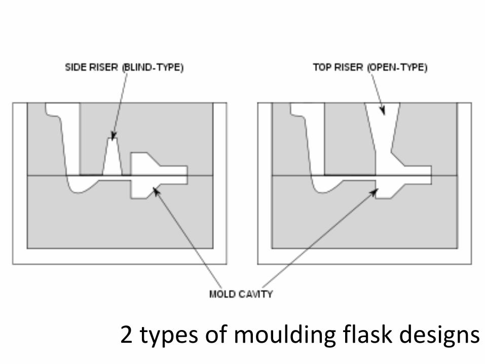
2 types of moulding flask designs

Pattern having core prints.
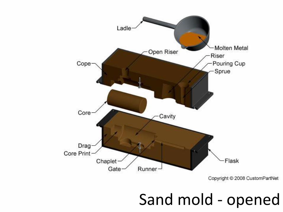
Sand mold - opened

Sand mold - closed

Fig: Cope and drag pattern

Gating System
Gating system
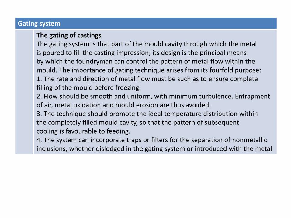
The gating of castings The gating system is that part of the mould cavity through which the metal is poured to fill the casting impression; its design is the principal means by which the foundryman can control the pattern of metal flow within the mould. The importance of gating technique arises from its fourfold purpose: 1. The rate and direction of metal flow must be such as to ensure complete filling of the mould before freezing. 2. Flow should be smooth and uniform, with minimum turbulence. Entrapment of air, metal oxidation and mould erosion are thus avoided. 3. The technique should promote the ideal temperature distribution within the completely filled mould cavity, so that the pattern of subsequent cooling is favourable to feeding. 4. The system can incorporate traps or filters for the separation of nonmetallic inclusions, whether dislodged in the gating system or introduced with the metal
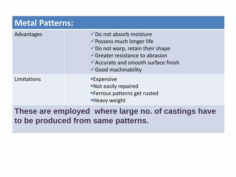
Metal Patterns: Advantages Do not absorb moisture
Possess much longer life Do not warp, retain their shape Greater resistance to abrasion Accurate and smooth surface finish Good machinability
Limitations Expensive Not easily repaired Ferrous patterns get rusted Heavy weight
These are employed where large no. of castings have
to be produced from same patterns.
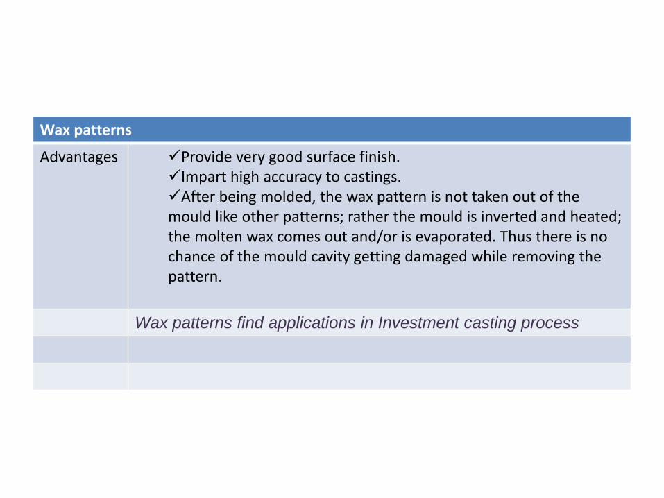
Wax patterns
Advantages Provide very good surface finish. Impart high accuracy to castings. After being molded, the wax pattern is not taken out of the mould like other patterns; rather the mould is inverted and heated; the molten wax comes out and/or is evaporated. Thus there is no chance of the mould cavity getting damaged while removing the pattern.
Wax patterns find applications in Investment casting process
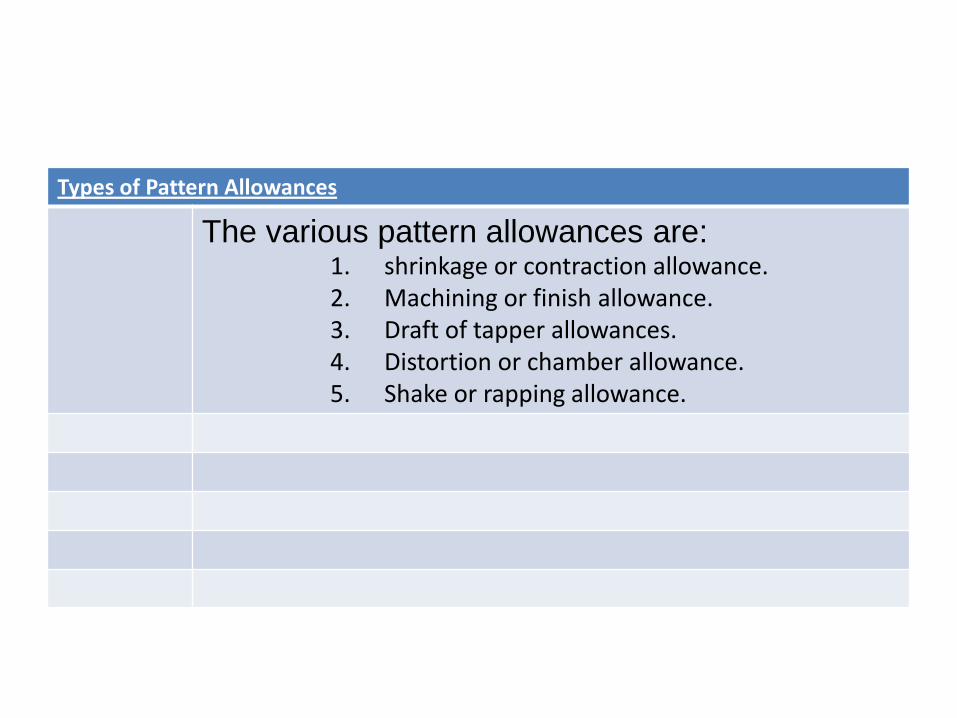
Types of Pattern Allowances
The various pattern allowances are: 1. shrinkage or contraction allowance. 2. Machining or finish allowance. 3. Draft of tapper allowances. 4. Distortion or chamber allowance. 5. Shake or rapping allowance.
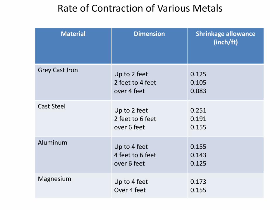
Rate of Contraction of Various Metals
Material Dimension Shrinkage allowance (inch/ft)
Grey Cast Iron Up to 2 feet 2 feet to 4 feet over 4 feet
0.125 0.105 0.083
Cast Steel Up to 2 feet 2 feet to 6 feet over 6 feet
0.251 0.191 0.155
Aluminum Up to 4 feet 4 feet to 6 feet over 6 feet
0.155 0.143 0.125
Magnesium Up to 4 feet Over 4 feet
0.173 0.155
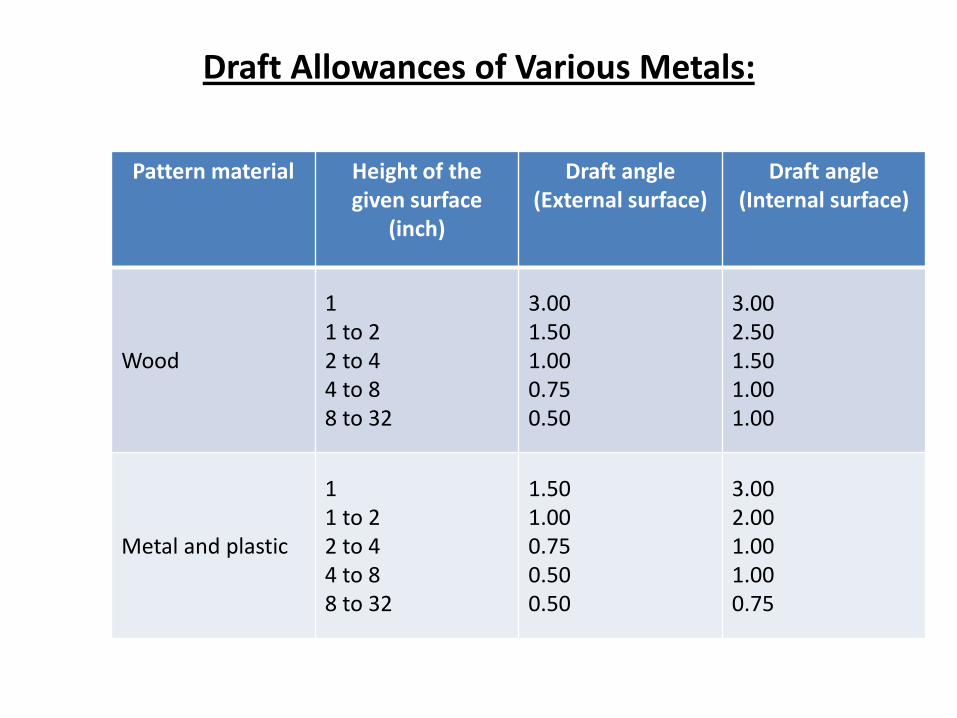
Draft Allowances of Various Metals:
Pattern material Height of the given surface
(inch)
Draft angle (External surface)
Draft angle (Internal surface)
Wood
1 1 to 2 2 to 4 4 to 8 8 to 32
3.00 1.50 1.00 0.75 0.50
3.00 2.50 1.50 1.00 1.00
Metal and plastic
1 1 to 2 2 to 4 4 to 8 8 to 32
1.50 1.00 0.75 0.50 0.50
3.00 2.00 1.00 1.00 0.75

Machining Allowances of Various Metals
Metal Dimension (inch) Allowance (inch)
Cast iron Up to 12 12 to 20 20 to 40
0.12 0.20 0.25
Cast steel Up to 6 6 to 20 20 to 40
0.12 0.25 0.30
Non ferrous Up to 8 8 to 12 12 to 40
0.09 0.12 0.16

Moulding Materials
Major part of Moulding material in sand casting are 1. 70-85% silica sand (SiO2) 2. 10-12% bonding material e.g., clay cereal etc. 3. 3-6% water
Requirements of molding sand are: (a) Refractoriness (b) Cohesiveness (c) Permeability (d) Collapsibility
The performance of mould depends on following factors:
(a) Permeability (b) Green strength (c) Dry strength
Moulding Sand
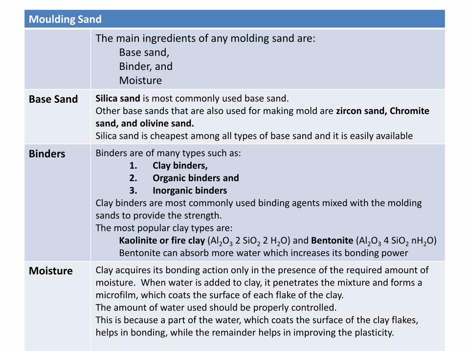
The main ingredients of any molding sand are: Base sand, Binder, and Moisture
Base Sand Silica sand is most commonly used base sand. Other base sands that are also used for making mold are zircon sand, Chromite sand, and olivine sand. Silica sand is cheapest among all types of base sand and it is easily available
Binders Binders are of many types such as: 1. Clay binders, 2. Organic binders and 3. Inorganic binders
Clay binders are most commonly used binding agents mixed with the molding sands to provide the strength. The most popular clay types are:
Kaolinite or fire clay (Al2O3 2 SiO2 2 H2O) and Bentonite (Al2O3 4 SiO2 nH2O) Bentonite can absorb more water which increases its bonding power
Moisture Clay acquires its bonding action only in the presence of the required amount of moisture. When water is added to clay, it penetrates the mixture and forms a microfilm, which coats the surface of each flake of the clay. The amount of water used should be properly controlled. This is because a part of the water, which coats the surface of the clay flakes, helps in bonding, while the remainder helps in improving the plasticity.

A Typical Composition of Molding Sand:
Molding Sand Constituent Weight Percent
Silica sand 92
Clay (Sodium Bentonite) 8
Water 4
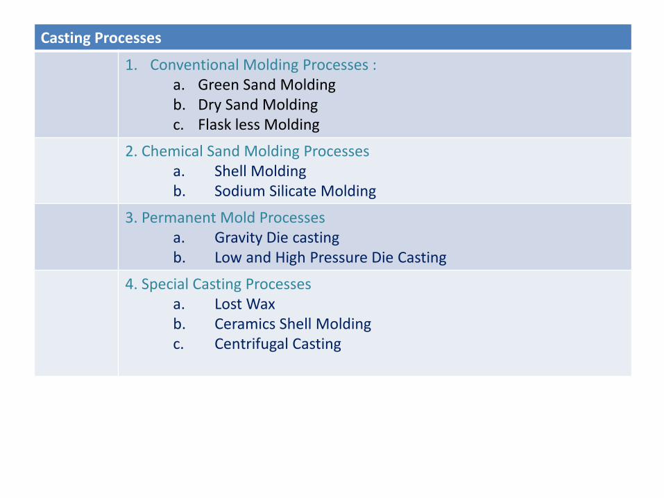
Casting Processes
1. Conventional Molding Processes : a. Green Sand Molding b. Dry Sand Molding c. Flask less Molding
2. Chemical Sand Molding Processes a. Shell Molding b. Sodium Silicate Molding
3. Permanent Mold Processes a. Gravity Die casting b. Low and High Pressure Die Casting
4. Special Casting Processes a. Lost Wax b. Ceramics Shell Molding c. Centrifugal Casting
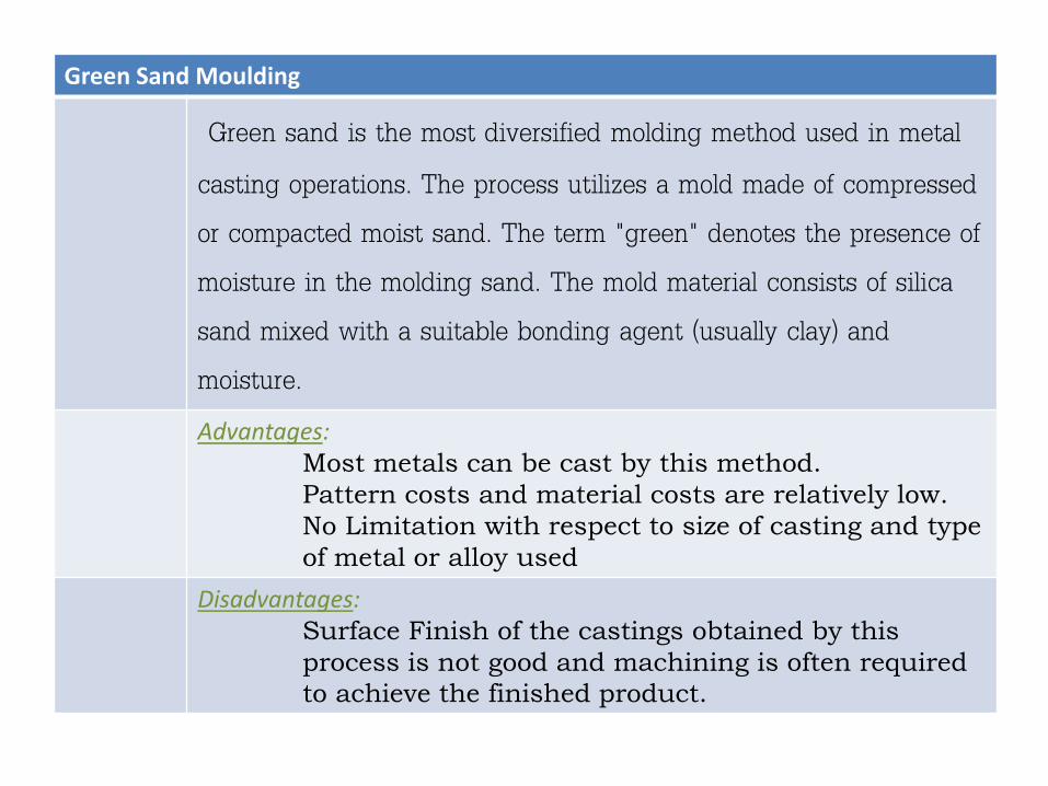
Green Sand Moulding
Green sand is the most diversified molding method used in metal
casting operations. The process utilizes a mold made of compressed
or compacted moist sand. The term "green" denotes the presence of
moisture in the molding sand. The mold material consists of silica
sand mixed with a suitable bonding agent (usually clay) and
moisture.
Advantages: Most metals can be cast by this method.
Pattern costs and material costs are relatively low.
No Limitation with respect to size of casting and type
of metal or alloy used
Disadvantages: Surface Finish of the castings obtained by this
process is not good and machining is often required
to achieve the finished product.
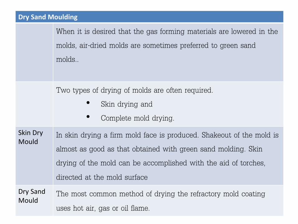
Dry Sand Moulding
When it is desired that the gas forming materials are lowered in the
molds, air-dried molds are sometimes preferred to green sand
molds..
Two types of drying of molds are often required.
• Skin drying and
• Complete mold drying.
Skin Dry Mould
In skin drying a firm mold face is produced. Shakeout of the mold is
almost as good as that obtained with green sand molding. Skin
drying of the mold can be accomplished with the aid of torches,
directed at the mold surface Dry Sand Mould
The most common method of drying the refractory mold coating
uses hot air, gas or oil flame.
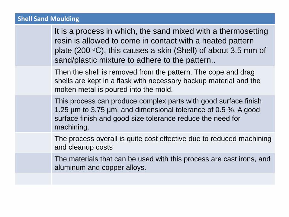
Shell Sand Moulding
It is a process in which, the sand mixed with a thermosetting
resin is allowed to come in contact with a heated pattern
plate (200 oC), this causes a skin (Shell) of about 3.5 mm of
sand/plastic mixture to adhere to the pattern..
Then the shell is removed from the pattern. The cope and drag
shells are kept in a flask with necessary backup material and the
molten metal is poured into the mold.
This process can produce complex parts with good surface finish
1.25 µm to 3.75 µm, and dimensional tolerance of 0.5 %. A good
surface finish and good size tolerance reduce the need for
machining.
The process overall is quite cost effective due to reduced machining
and cleanup costs
The materials that can be used with this process are cast irons, and
aluminum and copper alloys.
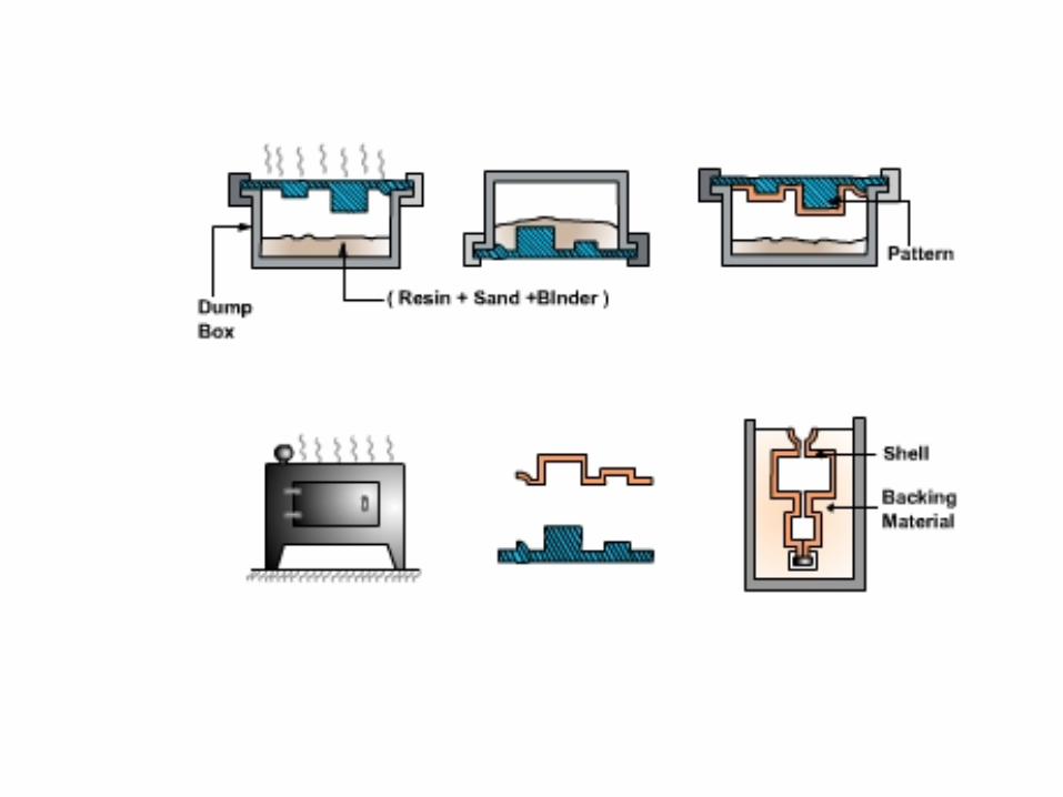
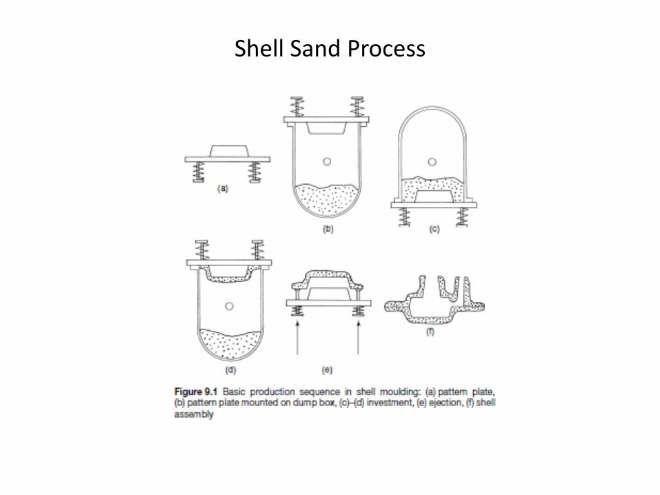
Shell Sand Process

Centrifugal Casting
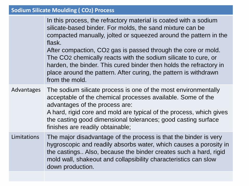
Sodium Silicate Moulding ( CO2) Process
In this process, the refractory material is coated with a sodium
silicate-based binder. For molds, the sand mixture can be
compacted manually, jolted or squeezed around the pattern in the
flask.
After compaction, CO2 gas is passed through the core or mold.
The CO2 chemically reacts with the sodium silicate to cure, or
harden, the binder. This cured binder then holds the refractory in
place around the pattern. After curing, the pattern is withdrawn
from the mold.
Advantages The sodium silicate process is one of the most environmentally
acceptable of the chemical processes available. Some of the
advantages of the process are:
A hard, rigid core and mold are typical of the process, which gives
the casting good dimensional tolerances; good casting surface
finishes are readily obtainable;
Limitations The major disadvantage of the process is that the binder is very
hygroscopic and readily absorbs water, which causes a porosity in
the castings.. Also, because the binder creates such a hard, rigid
mold wall, shakeout and collapsibility characteristics can slow
down production.
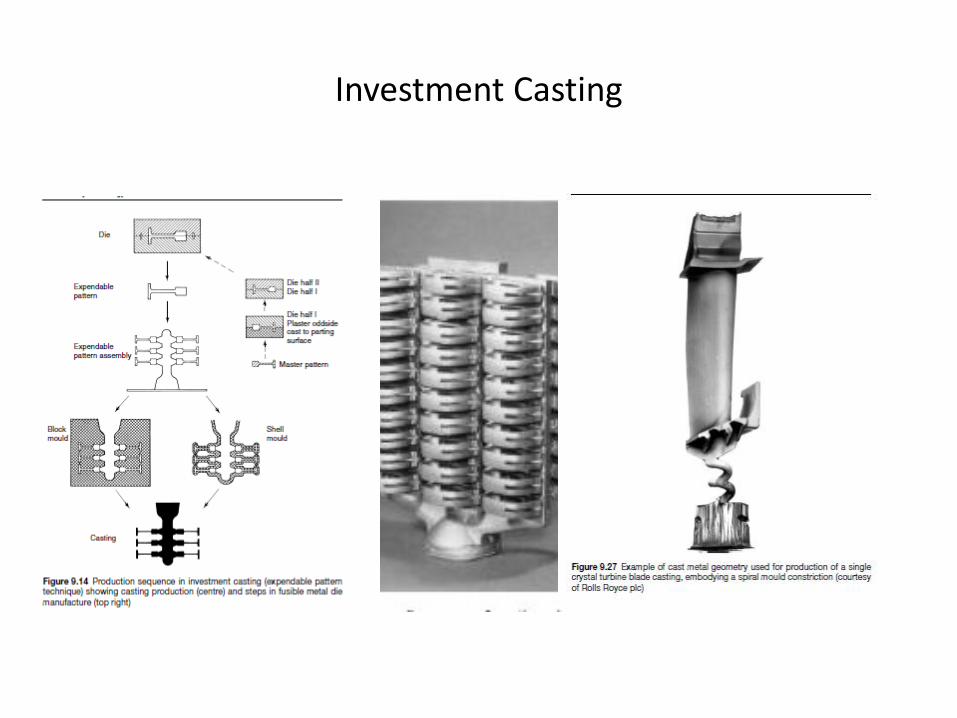
Investment Casting

Solidification and Cooling:
The properties of the casting significantly depends on the solidification time/ cooling rate.
Shrinkage of casting, during cooling of solidified metal should not be restrained by the mould material, otherwise internal stresses may develop and form cracks in casting.
Proper care should be taken at the design stage of casting so that shrinkage can occur without casting defects.

Removal, Cleaning, Finishing and Inspection
After the casting is removed from the mould it is thoroughly cleaned and the excess material usually along the parting line and the place where the molten metal was poured, is removed using a potable grinder.
White light inspection, pressure test, magnetic particle inspection, radiographic test, ultrasonic inspection etc. are used
Gray Cast Iron
Gray iron refers to a broad class of ferrous casting alloys normally
characterized by a microstructure of flake graphite in a ferrous matrix. Gray
irons are in essence iron-carbon-silicon alloys containing small quantities of
other elements. As a class, they vary widely in physical and mechanical
properties.
Gray irons have found wide acceptance based on a combination of
outstanding castability, excellent machinability, economics, and unique
properties

Solidification of Cast Iron
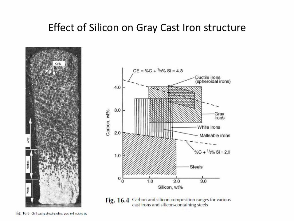
Effect of Silicon on Gray Cast Iron structure
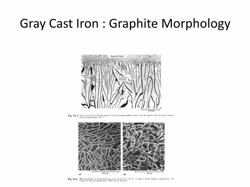
Gray Cast Iron : Graphite Morphology
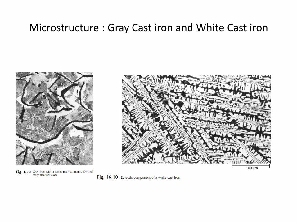
Microstructure : Gray Cast iron and White Cast iron

Grey Cast Iron Graphite
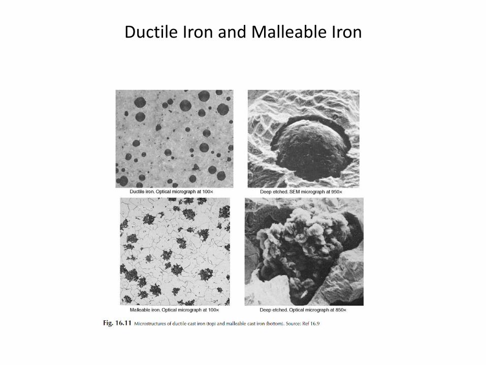
Ductile Iron and Malleable Iron
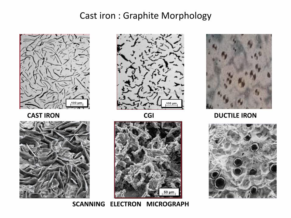
Cast iron : Graphite Morphology
ER&D\CGI\19-05-07
CAST IRON
SCANNING ELECTRON MICROGRAPH
CGI DUCTILE IRON

Graphite Morphology graphite flake distributions:
The mechanical and physical properties of gray iron are governed in part by the shape, size, amount, and distribution of the graphite flakes. There are five A to E (Fig. 4).
Type A graphite flakes are randomly distributed and oriented throughout the iron matrix. This type of graphite is found in irons that solidify with a minimum amount of undercooling, and type A is the structure desired if mechanical properties are to be optimized.
Type B graphite is formed in irons of near-eutectic composition that solidify with a greater amount of undercooling than that associated with type A graphite. Rosettes containing fine graphite, which are characteristic of type B, precipitate at the start of eutectic solidification
Types D and E graphite form when the amount of undercooling is high but is not sufficient to cause carbide formation. Both types are found in interdendritic regions. Type D graphite is randomly distributed, while the type E flakes have a preferred orientation. The manner in which the plane of polish intersects the graphite flakes may be responsible for this difference in orientation. Elements such as titanium and aluminum have been found to promote undercooled graphite structure.
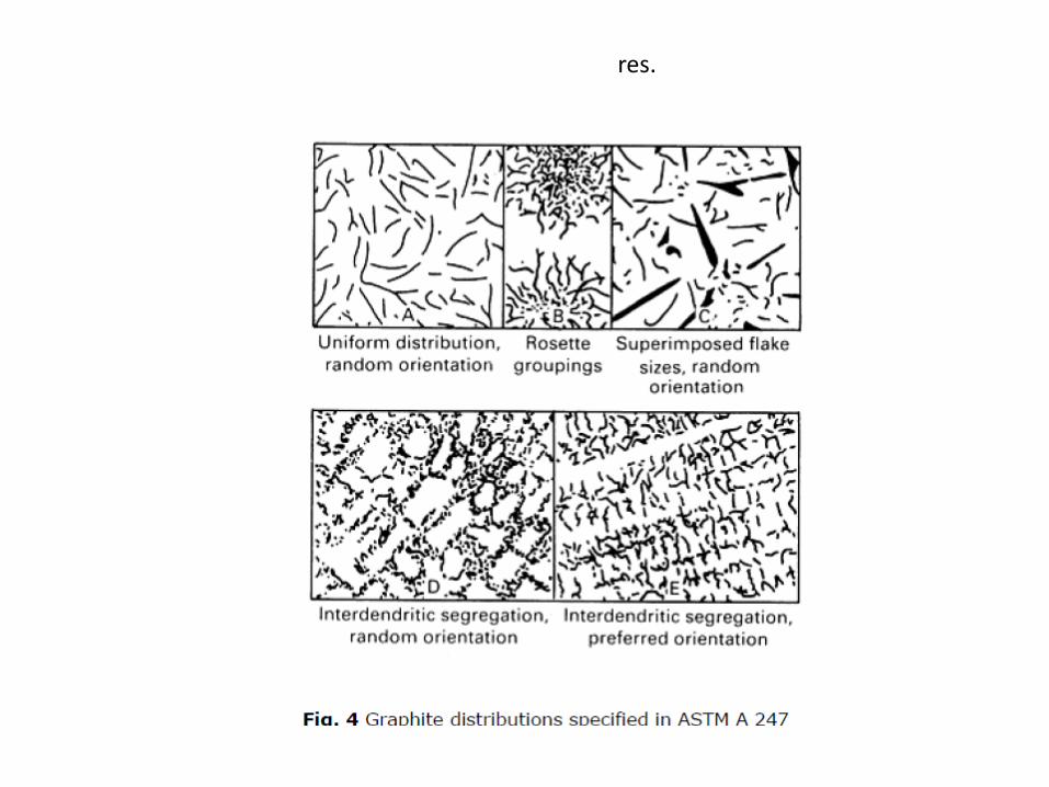
res.
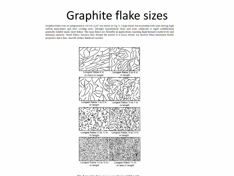
Graphite flake sizes

Gray CI Chemical Composition Composition
For purposes of clarity and simplicity, the chemical analyses of gray iron can be broken down into three categories : • Major elements. • Minor elements , normally low-level alloying elements that are critically
related to gray iron solidification. • Trace elements that affect the microstructure and/or properties of the GCI
Major Elements. The three major elements in gray iron are carbon, silicon, and iron. Most gray irons are produced with total carbon levels 3.0 to 3.5% and silicon 1.8 to 2.4%.
Gray irons are normally viewed as iron-carbon-silicon ternary alloys. The material exhibits eutectic solidification and also a solid-state eutectoid transformation. These two factors dominate the metallurgy of gray iron.
Both carbon and silicon influence the nature of iron castings. It is therefore necessary to develop an approximation of their impact on solidification. This has been accomplished through development of the concept of carbon equivalence (CE) as follows:
Most gray irons are hypoeutectic (that is, CE < 4.3). Nearly all of the mechanical and physical properties of gray iron are closely related to CE value.

Gray CI Chemical Composition
The minor elements
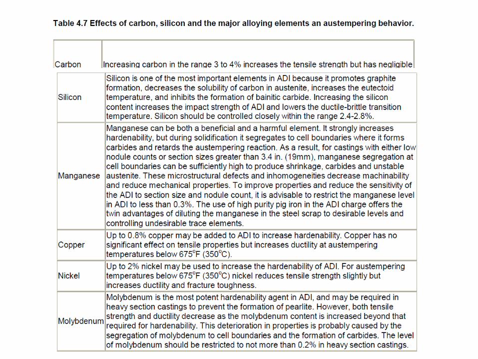
The minor elements in gray iron are phosphorus and the two interrelated elements manganese and sulphur. These elements, like carbon and silicon, are of significant importance in gray iron metallurgy.
Phosphorus is found in all gray irons. It is rarely added intentionally, but tends to come from pig iron or scrap. To some extent, it increases the fluidity of iron. Phosphorus forms a low-melting phosphide phase in gray iron that is commonly referred to as steadite. • At high levels, it can promote shrinkage porosity, • while very low levels can increase metal penetration into the mold . As a result, most castings are produced with 0.02 to 0.10% P Steadite in the presence of chromium forms a very hard phase which can adversely affect machinability but improve wear resistance.
Sulphur levels in gray iron are very important and to some extent are an area of current technical controversy. Sulphur plays a significant role in the nucleation of graphite in gray iron: on cell counts and chill depth . Sulphur levels in gray iron should be in the approximate range of 0.05 to 0.12% for optimum benefit. It is important that the sulfur content of iron be balanced with manganese to promote the formation of manganese sulfides.
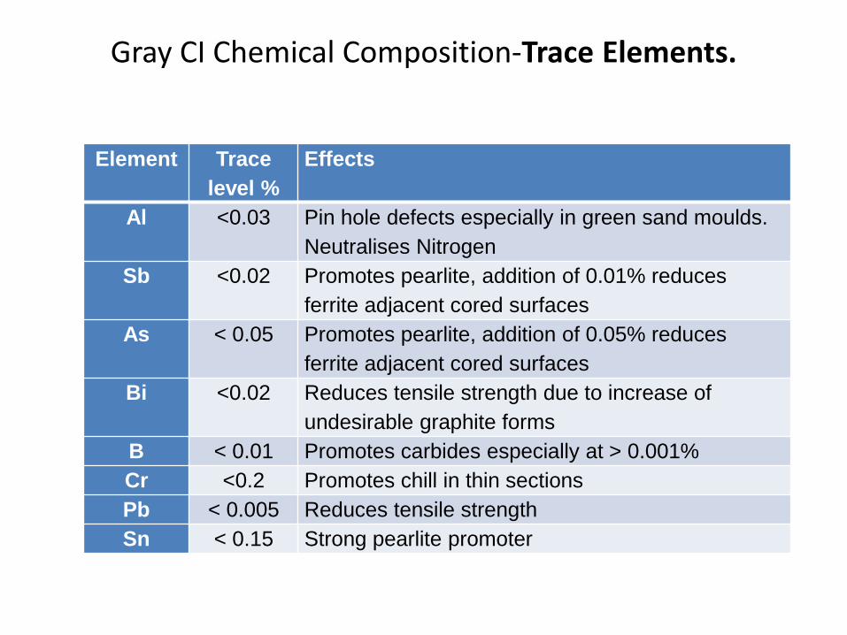
Gray CI Chemical Composition-Trace Elements.
Element Trace
level %
Effects
Al <0.03 Pin hole defects especially in green sand moulds.
Neutralises Nitrogen
Sb <0.02 Promotes pearlite, addition of 0.01% reduces
ferrite adjacent cored surfaces
As < 0.05 Promotes pearlite, addition of 0.05% reduces
ferrite adjacent cored surfaces
Bi <0.02 Reduces tensile strength due to increase of
undesirable graphite forms
B < 0.01 Promotes carbides especially at > 0.001%
Cr <0.2 Promotes chill in thin sections
Pb < 0.005 Reduces tensile strength
Sn < 0.15 Strong pearlite promoter
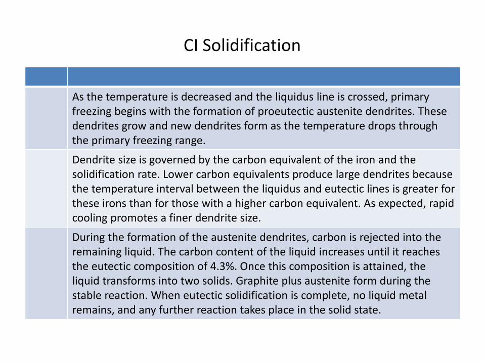
CI Solidification
As the temperature is decreased and the liquidus line is crossed, primary freezing begins with the formation of proeutectic austenite dendrites. These dendrites grow and new dendrites form as the temperature drops through the primary freezing range.
Dendrite size is governed by the carbon equivalent of the iron and the solidification rate. Lower carbon equivalents produce large dendrites because the temperature interval between the liquidus and eutectic lines is greater for these irons than for those with a higher carbon equivalent. As expected, rapid cooling promotes a finer dendrite size.
During the formation of the austenite dendrites, carbon is rejected into the remaining liquid. The carbon content of the liquid increases until it reaches the eutectic composition of 4.3%. Once this composition is attained, the liquid transforms into two solids. Graphite plus austenite form during the stable reaction. When eutectic solidification is complete, no liquid metal remains, and any further reaction takes place in the solid state.
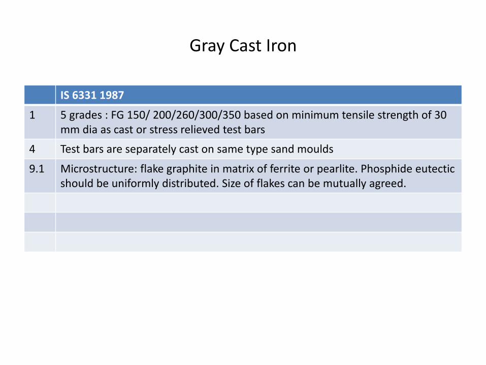
Gray Cast Iron
IS 6331 1987
1 5 grades : FG 150/ 200/260/300/350 based on minimum tensile strength of 30 mm dia as cast or stress relieved test bars
4 Test bars are separately cast on same type sand moulds
9.1 Microstructure: flake graphite in matrix of ferrite or pearlite. Phosphide eutectic should be uniformly distributed. Size of flakes can be mutually agreed.
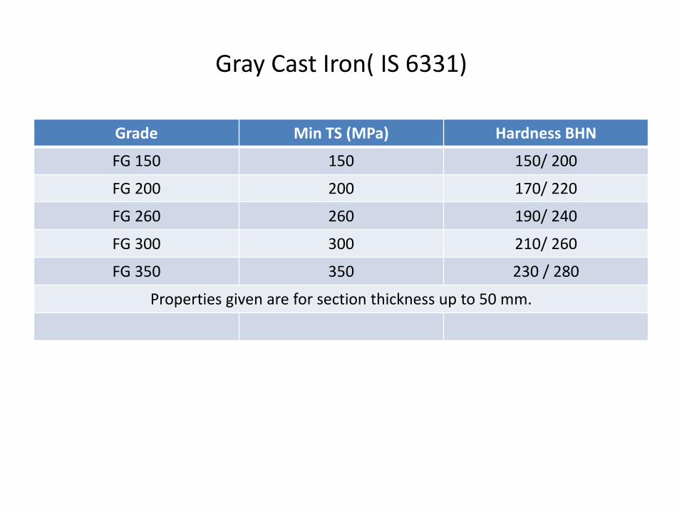
Gray Cast Iron( IS 6331)
Grade Min TS (MPa) Hardness BHN
FG 150 150 150/ 200
FG 200 200 170/ 220
FG 260 260 190/ 240
FG 300 300 210/ 260
FG 350 350 230 / 280
Properties given are for section thickness up to 50 mm.
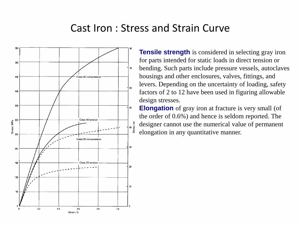
Cast Iron : Stress and Strain Curve
Tensile strength is considered in selecting gray iron
for parts intended for static loads in direct tension or
bending. Such parts include pressure vessels, autoclaves
housings and other enclosures, valves, fittings, and
levers. Depending on the uncertainty of loading, safety
factors of 2 to 12 have been used in figuring allowable
design stresses.
Elongation of gray iron at fracture is very small (of
the order of 0.6%) and hence is seldom reported. The
designer cannot use the numerical value of permanent
elongation in any quantitative manner.
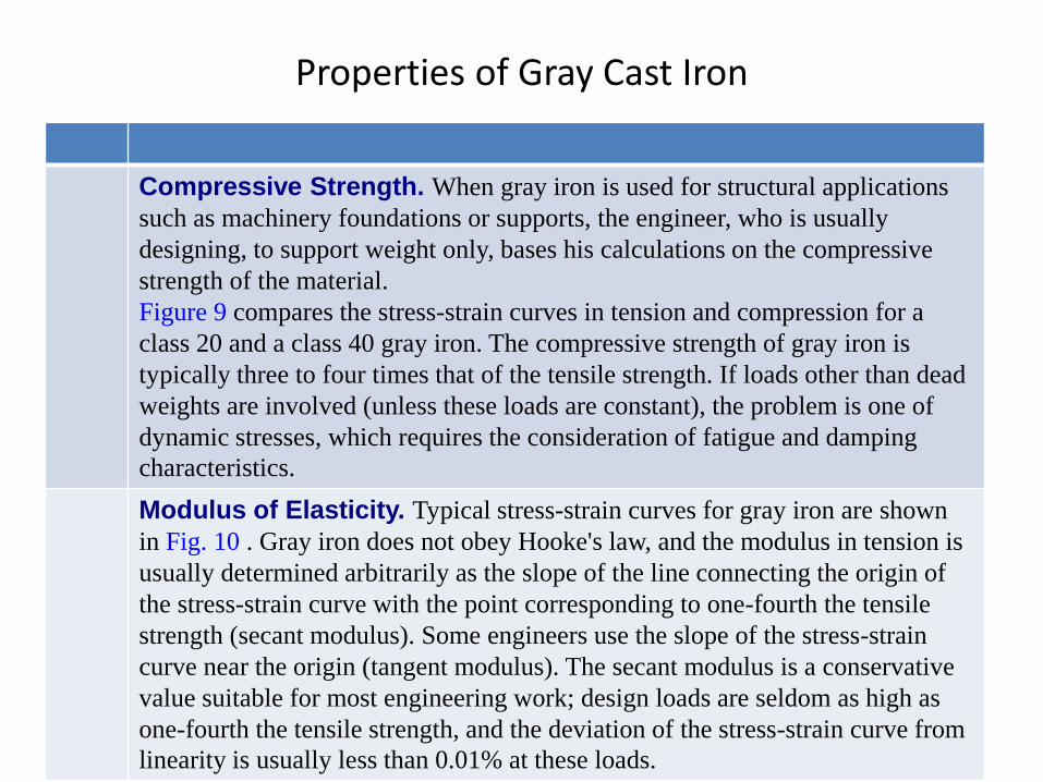
Properties of Gray Cast Iron
Compressive Strength. When gray iron is used for structural applications
such as machinery foundations or supports, the engineer, who is usually
designing, to support weight only, bases his calculations on the compressive
strength of the material.
Figure 9 compares the stress-strain curves in tension and compression for a
class 20 and a class 40 gray iron. The compressive strength of gray iron is
typically three to four times that of the tensile strength. If loads other than dead
weights are involved (unless these loads are constant), the problem is one of
dynamic stresses, which requires the consideration of fatigue and damping
characteristics.
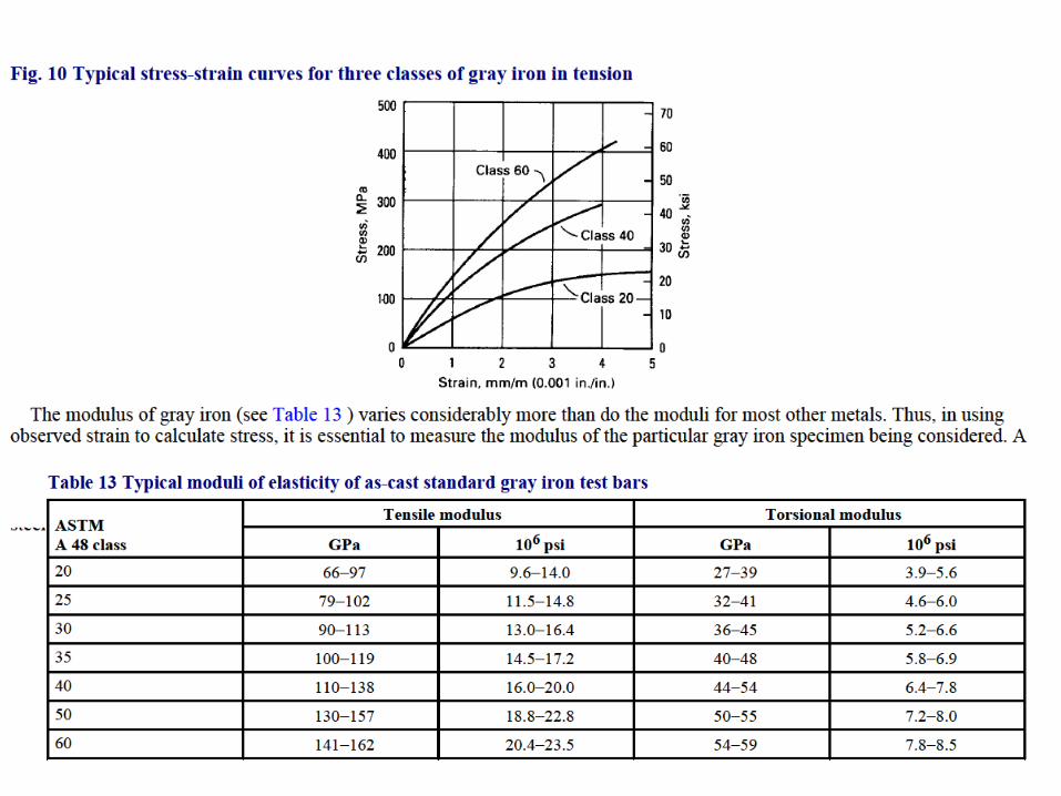
Modulus of Elasticity. Typical stress-strain curves for gray iron are shown
in Fig. 10 . Gray iron does not obey Hooke's law, and the modulus in tension is
usually determined arbitrarily as the slope of the line connecting the origin of
the stress-strain curve with the point corresponding to one-fourth the tensile
strength (secant modulus). Some engineers use the slope of the stress-strain
curve near the origin (tangent modulus). The secant modulus is a conservative
value suitable for most engineering work; design loads are seldom as high as
one-fourth the tensile strength, and the deviation of the stress-strain curve from
linearity is usually less than 0.01% at these loads.
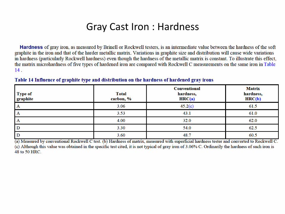
Gray Cast Iron : Hardness
Gray Cast Iron : Notch Sensitivity
Fatigue Notch Sensitivity. In general, very little allowance need be made
for a reduction in fatigue strength caused by notches or abrupt changes of
section in gray iron members. The low-strength irons exhibit only a slight
reduction in strength in the presence of fillets and holes.
This characteristic can be explained by considering the graphite flakes in
gray iron to be internal notches. Thus, gray iron can be thought of as a
material that is already full of notches and that therefore has little or no
sensitivity to the presence of additional notches resulting from design
features. The strength-reducing effect of the internal notches is included in
the fatigue limit values determined by conventional laboratory tests with
smooth bars.

Gray Cast Iron : Wear Properties Gray iron is used widely for machine components that must resist wear.
Different types of iron, however, exhibit great differences in wear
characteristics.
Relative hardness between mating parts also may be important to optimum
wear resistance. Frequently, a hardness difference no greater than 10 points
on the Brinell scale is considered optimum.
For components in sliding contact, such as engine cylinders, valve guides, and
latheways, the recognized types of wear are cutting wear, abrasive wear,
adhesive wear, and corrosive wear.
Cutting wear is caused by the mechanical removal of surface metal as a
result of surface roughness and is similar to the action of a file. It usually
occurs during the breaking in of new parts.
Abrasive wear is caused by the cutting action or loose, abrasive particles that
get between the contacting faces and act like a lapping compound. Under
some circumstances, abrasive particles embedded in one or both of the
contacting faces can produce a similar action.
Adhesive wear is caused by metal-to-metal contact, resultant welding, and
the breaking of those welds
Corrosive wear is a special type of wear that combines abrasion or adhesion
with the chemical action of the environment
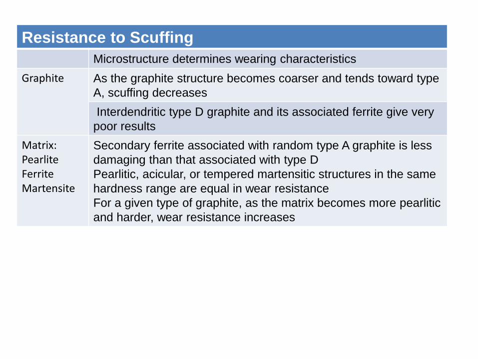
Resistance to Scuffing
Microstructure determines wearing characteristics
Graphite As the graphite structure becomes coarser and tends toward type
A, scuffing decreases
Interdendritic type D graphite and its associated ferrite give very
poor results
Matrix: Pearlite Ferrite Martensite
Secondary ferrite associated with random type A graphite is less
damaging than that associated with type D
Pearlitic, acicular, or tempered martensitic structures in the same
hardness range are equal in wear resistance
For a given type of graphite, as the matrix becomes more pearlitic
and harder, wear resistance increases
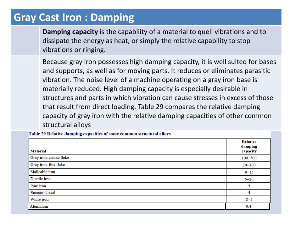
Gray Cast Iron : Damping Damping capacity is the capability of a material to quell vibrations and to dissipate the energy as heat, or simply the relative capability to stop vibrations or ringing.
Because gray iron possesses high damping capacity, it is well suited for bases and supports, as well as for moving parts. It reduces or eliminates parasitic vibration. The noise level of a machine operating on a gray iron base is materially reduced. High damping capacity is especially desirable in structures and parts in which vibration can cause stresses in excess of those that result from direct loading. Table 29 compares the relative damping capacity of gray iron with the relative damping capacities of other common structural alloys

CGI - Automotive components
• Engine block and heads
• Exhaust manifolds.
• Pump housings.
• Brackets
• Piston rings.
ER&D\CGI\19-05-07
PRODUCTION METHODS FOR CGI
• Treatment with Magnesium
• Treatment With Magnesium and Titanium
• In the Titanium process , formation of hard titanium carbonitride inclusions increases abrasive wear
– Cannot be tolerated in machining
ER&D\CGI\19-05-07
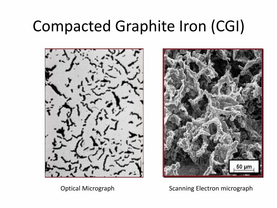
Compacted Graphite Iron (CGI)
ER&D\CGI\19-05-07
Optical Micrograph Scanning Electron micrograph
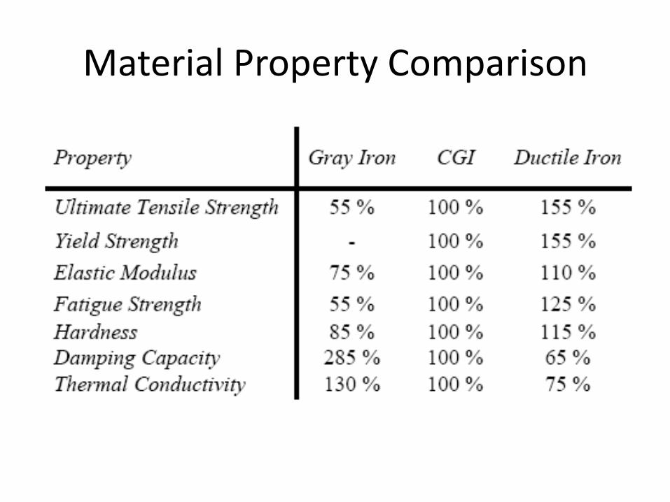
Material Property Comparison
ER&D\CGI\19-05-07

CGI - Satisfies the Requirement
• Advantages in comparison to Grey Iron:
– Improved tensile strength (70% Higher)
– Improved fatigue strength (Higher Twice)
– Improved elastic modulus (35% Higher)
– Better ductility
– Better surface finish
• Advantages in comparison to Ductile Iron:
– Higher thermal conductivity.
– Higher damping capacity.
– Better machinability.
ER&D\CGI\19-05-07
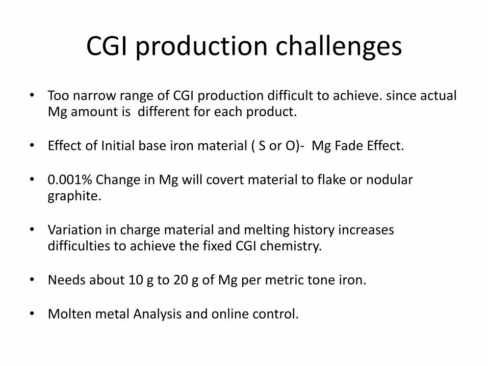
CGI production challenges
• Too narrow range of CGI production difficult to achieve. since actual Mg amount is different for each product.
• Effect of Initial base iron material ( S or O)- Mg Fade Effect.
• 0.001% Change in Mg will covert material to flake or nodular graphite.
• Variation in charge material and melting history increases difficulties to achieve the fixed CGI chemistry.
• Needs about 10 g to 20 g of Mg per metric tone iron.
• Molten metal Analysis and online control.
ER&D\CGI\19-05-07

Users of CGI
• Audi.
• Daimler Chrysler
• Ford.
• Hyundai.
• PSA and Volkswagen.
• General electric.
• Toyato
ER&D\CGI\19-05-07
MANUFACTURERS OF CGI
• SINTERCAST,Sweden.
• TUPY FOUNDRIES,USA.
• Elkem foundries.Norway.
• Doosan Infracore Co. Ltd,German.
• CASKOD foundry,Japan.
• PROMETAL, German.
ER&D\CGI\19-05-07
Results and discussions for effect of cutting and Wear
• Under same cutting conditions the cutting force required for CGI is 15-25% more than that of Gray iron, also provides good surface finish result compared to that of Gray iron.
• Load variation on the Wear rate proved that the wear rate of CGI is lesser than Gray iron under same conditions for dry and lubricated Wear.
ER&D\CGI\19-05-07
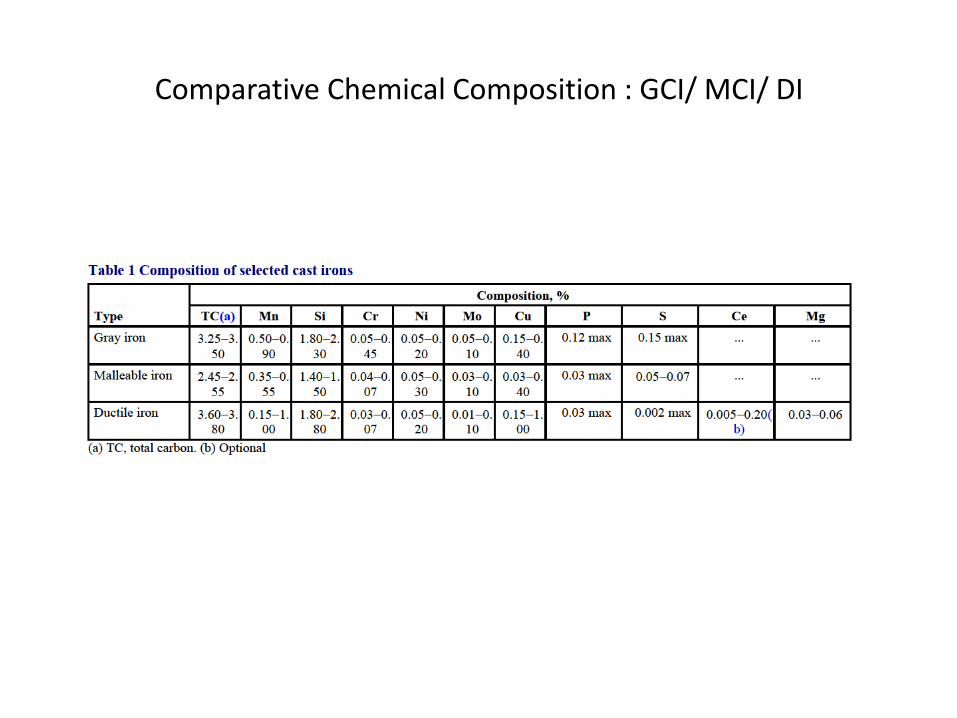
Comparative Chemical Composition : GCI/ MCI/ DI

Ductile Iron – Mg Treatment ladle
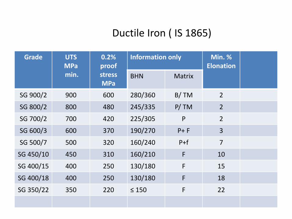
Grade UTS MPa min.
0.2% proof stress MPa
Information only Min. % Elonation
BHN Matrix
SG 900/2 900 600 280/360 B/ TM 2
SG 800/2 800 480 245/335 P/ TM 2
SG 700/2 700 420 225/305 P 2
SG 600/3 600 370 190/270 P+ F 3
SG 500/7 500 320 160/240 P+f 7
SG 450/10 450 310 160/210 F 10
SG 400/15 400 250 130/180 F 15
SG 400/18 400 250 130/180 F 18
SG 350/22 350 220 ≤ 150 F 22
Ductile Iron ( IS 1865)
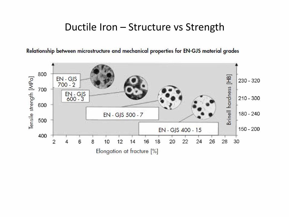
Ductile Iron – Structure vs Strength
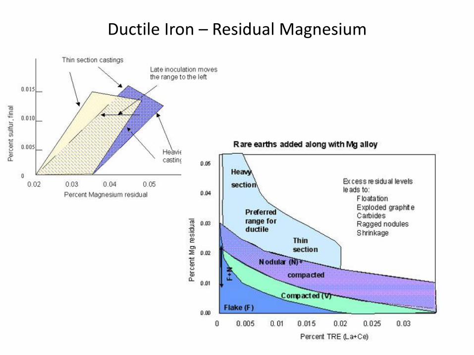
Ductile Iron – Residual Magnesium

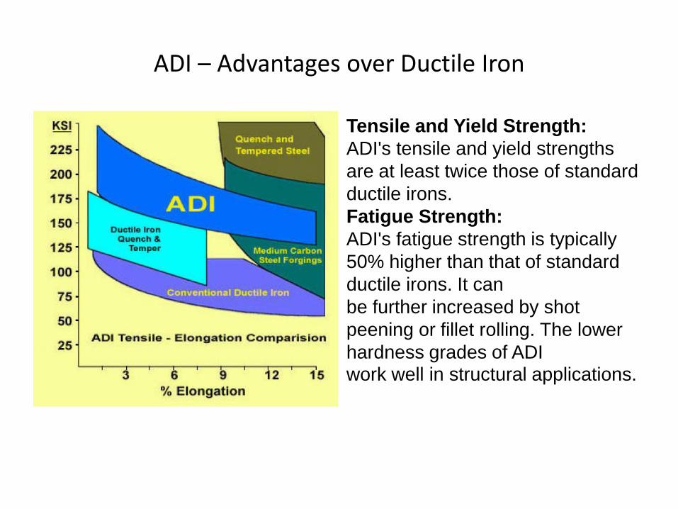
ADI – Advantages over Ductile Iron
Tensile and Yield Strength:
ADI's tensile and yield strengths
are at least twice those of standard
ductile irons.
Fatigue Strength:
ADI's fatigue strength is typically
50% higher than that of standard
ductile irons. It can
be further increased by shot
peening or fillet rolling. The lower
hardness grades of ADI work well in structural applications.

ADI - Advantages
Toughness:
ADI's excellent impact and fracture-toughness properties make it ideal for
applications such as ground-engaging tools.
Wear Characteristics:
The higher hardness grades of ADI are excellent for wear applications. Unlike
casehardened materials, typically the ADI is uniformly hardened throughout the
part. Also, ADI work-hardens when stressed. This produces a thin surface of very
hard martensite where wear resistance is most needed.
Cost-effectiveness:
ADI is usually 15% to 20% less costly than steel forgings or castings. It is the
most economical way of obtaining tensile, yield, or fatigue strength. ADI often
competes favorably with heat-treated and alloy steels for heavy-duty applications
where reliabilty is crucial.
Properties of ADI Compared to Steel:
ADI is much easier to cast than steel
ADI is approximately 9% lighter than steel
ADI has minimal draft requirements compared with steel forgings
ADI loses less of its toughness than steel at sub-zero temperatures
ADI work hardens when stressed
ADI has more damping capacity than steel

Ductile Iron vs ADI
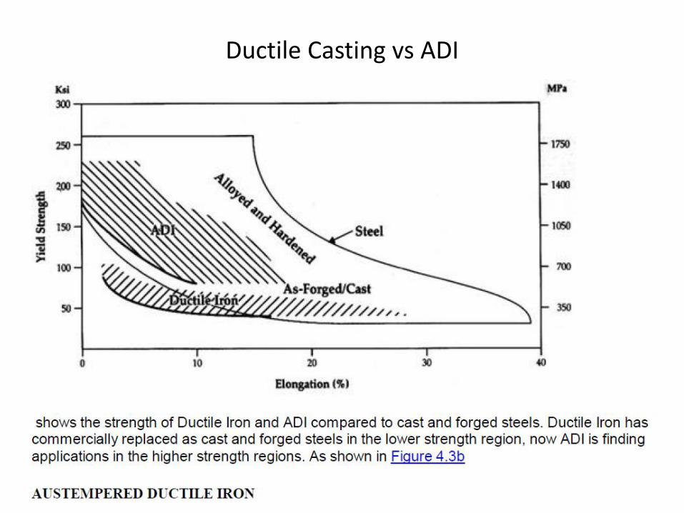
Ductile Casting vs ADI

Ductile Iron/ ADI ; Mechanical Properties
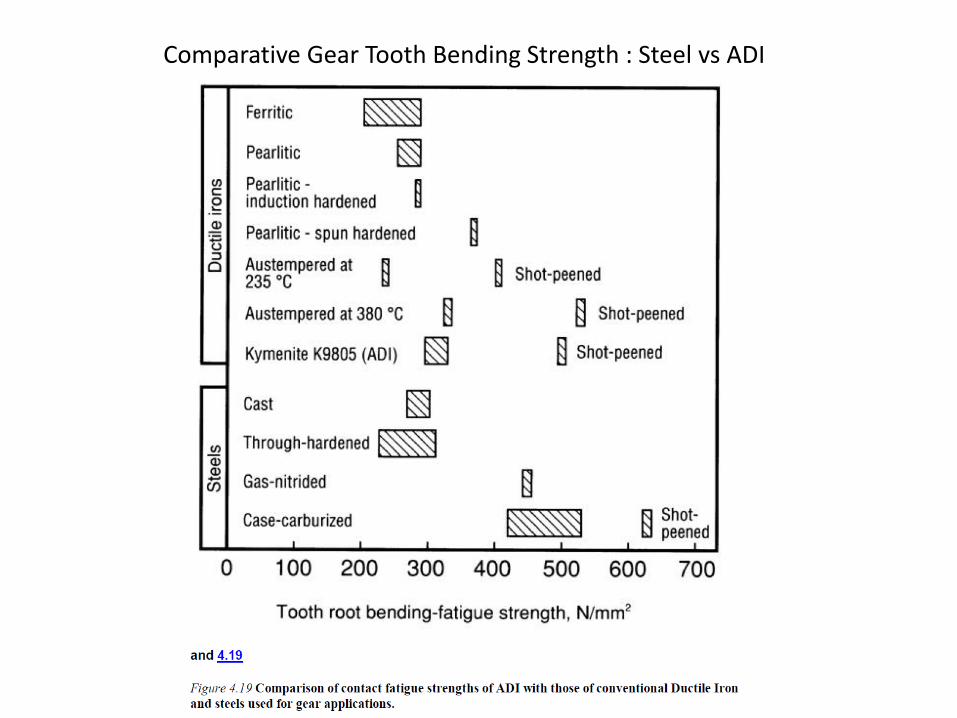
Comparative Gear Tooth Bending Strength : Steel vs ADI

Comparative Gear Contact fatigue strength : Steel vs ADI

ADI Energy consumption
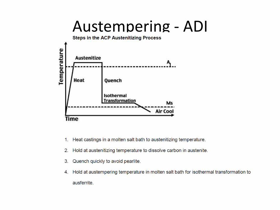
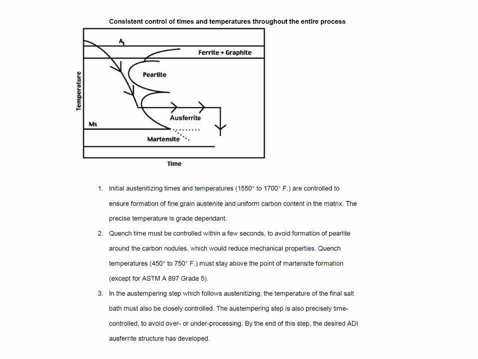
Austempering - ADI
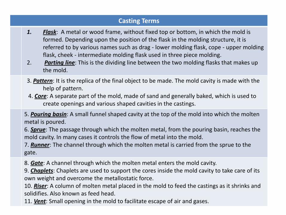
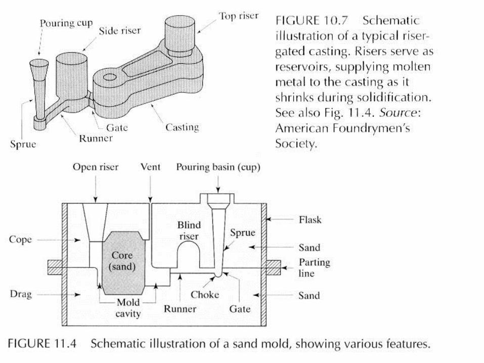
Casting Terms
1. Flask: A metal or wood frame, without fixed top or bottom, in which the mold is formed. Depending upon the position of the flask in the molding structure, it is referred to by various names such as drag - lower molding flask, cope - upper molding flask, cheek - intermediate molding flask used in three piece molding.
2. Parting line: This is the dividing line between the two molding flasks that makes up the mold.
3. Pattern: It is the replica of the final object to be made. The mold cavity is made with the help of pattern.
4. Core: A separate part of the mold, made of sand and generally baked, which is used to create openings and various shaped cavities in the castings.
5. Pouring basin: A small funnel shaped cavity at the top of the mold into which the molten metal is poured. 6. Sprue: The passage through which the molten metal, from the pouring basin, reaches the mold cavity. In many cases it controls the flow of metal into the mold. 7. Runner: The channel through which the molten metal is carried from the sprue to the gate.
8. Gate: A channel through which the molten metal enters the mold cavity. 9. Chaplets: Chaplets are used to support the cores inside the mold cavity to take care of its own weight and overcome the metallostatic force. 10. Riser: A column of molten metal placed in the mold to feed the castings as it shrinks and solidifies. Also known as feed head. 11. Vent: Small opening in the mold to facilitate escape of air and gases.